EP1061371A2 - Method and device for controlling the liquid absorption of an analysing element test layer - Google Patents
Method and device for controlling the liquid absorption of an analysing element test layer Download PDFInfo
- Publication number
- EP1061371A2 EP1061371A2 EP00111467A EP00111467A EP1061371A2 EP 1061371 A2 EP1061371 A2 EP 1061371A2 EP 00111467 A EP00111467 A EP 00111467A EP 00111467 A EP00111467 A EP 00111467A EP 1061371 A2 EP1061371 A2 EP 1061371A2
- Authority
- EP
- European Patent Office
- Prior art keywords
- test layer
- light
- film
- analysis
- liquid
- Prior art date
- Legal status (The legal status is an assumption and is not a legal conclusion. Google has not performed a legal analysis and makes no representation as to the accuracy of the status listed.)
- Granted
Links
Images


Classifications
-
- G—PHYSICS
- G01—MEASURING; TESTING
- G01N—INVESTIGATING OR ANALYSING MATERIALS BY DETERMINING THEIR CHEMICAL OR PHYSICAL PROPERTIES
- G01N35/00—Automatic analysis not limited to methods or materials provided for in any single one of groups G01N1/00 - G01N33/00; Handling materials therefor
- G01N35/00029—Automatic analysis not limited to methods or materials provided for in any single one of groups G01N1/00 - G01N33/00; Handling materials therefor provided with flat sample substrates, e.g. slides
-
- G—PHYSICS
- G01—MEASURING; TESTING
- G01N—INVESTIGATING OR ANALYSING MATERIALS BY DETERMINING THEIR CHEMICAL OR PHYSICAL PROPERTIES
- G01N21/00—Investigating or analysing materials by the use of optical means, i.e. using sub-millimetre waves, infrared, visible or ultraviolet light
- G01N21/84—Systems specially adapted for particular applications
- G01N21/8483—Investigating reagent band
Definitions
- the invention relates to a method for controlling the Liquid absorption of a test layer of an analysis element as well as a corresponding analysis system from analysis elements and one designed for their evaluation Evaluation device.
- a liquid sample especially a body fluid of humans or animals
- carrier-related tests used.
- analysis elements are used in which reagents in one or more test layers are embedded.
- For Carrying out a reaction is using the analysis element the sample in contact.
- the reaction of sample and Reagent leads to a visual or with the help of an evaluation device (mostly reflection photometric) evaluable characteristic change for the analysis of the Analysis element.
- the evaluation device is usually used to evaluate a very specific type of analytical elements of a particular Manufacturer suitable.
- the analysis elements and that Evaluation devices form mutually coordinated devices Ingredients and are usually total referred to as an analysis system.
- analysis elements There are numerous different types of analysis elements known, which is characterized by the measuring principle (e.g. optical or electrochemical) and the reagents used as well by their structure, in particular by the arrangement and Fasten the test layers, differentiate. Common are in particular strip-shaped analysis elements (Test strips) made from an elongated plastic strip ("Base strip”) and at least one attached to it Test layer exist. Another common one The analysis element type is similar to a plastic frame a photographic slide in which at least one test layer is framed.
- test layers are made of an absorbent material, such as paper or porous plastic. If you are performing an analysis on the sample liquid brought into contact, they suck liquid in itself. For a correct analysis it is important that this fluid intake is even and completely done. Every test should be the same, the Suction rate of the test layer corresponding amount of liquid absorbed and evenly distributed in the test layer become.
- EP-0087466 contains an analysis system described in which due to the optical absorption of water in the infrared range an estimate of made of a sample layer becomes.
- a characteristic of fluid intake The test layer is used to generate a light signal with primary light (infrared light with a wavelength of about 2 ⁇ m) and that from the test layer diffusely reflected secondary light by means of a light receiver detected.
- the intensity of the reflected Light is both in the dry state of the analysis element as well as after contacting the sample. To provide information about that in the test layer Gaining the amount of liquid absorbed becomes the difference of these two light signals with a reference signal compared.
- the invention is based on the object a method and device for control the liquid absorption of a test layer to provide that through improved reliability distinguished.
- the control of fluid intake relates to usually on the in the flow path of the liquid last test layer of the analysis element.
- the invention is for controlling fluid intake any absorbent test layer one Suitable analysis element, provided that this test layer in direct contact with an optically transparent Foil piece stands.
- absorbent is general as a name for every form of fluid intake to understand and includes not only that by capillary action Absorbance caused by porous materials but also the fluid intake based on a swelling process.
- Optically transparent plastic films are used in the construction of analysis elements especially as test layer supports used in cases where the test layer with the piece of film is firmly connected.
- Foil piece which is a test layer carrier film for the Test layer forms, directly coated with the test layer his. This is common for test layers, that have no self-supporting properties.
- test films Test layers by coating a substrate with a thin film of a film-forming material become.
- Swellable in particular are known Test films based on gelatin and non-swelling porous Test films based on a dispersion film former.
- the film-forming mass used for film formation contains in addition to the reagents usually solid components, such as especially pigments and diatomaceous earth, which the layer Give desired opacity and absorbency.
- the invention has proven itself in test layers, which contain a dispersion film former and a pigment.
- Such test layers are for example in the U.S. Patents 5,169,787 and 5,536,470.
- the transparent foils used in analysis elements have a very small thickness of usually less than 0.2 mm. Accordingly, the surface area of the peripheral surface (ie the cut surface perpendicular to the surface area of the film on its circumference) is very small. For example, in the case of a square piece of film with an edge length of 6 mm, the peripheral surface consists of four sections, each of which has an area of only 1.2 mm 2 . In contrast, the main surfaces (top and bottom) each have an area of 36 mm 2 .
- the exit cross-section for light from the peripheral surface is very small, it was found in the context of the invention that the light emerging from the peripheral surface has such a high intensity that it can be measured without particular problems.
- the percentage change the light intensity emerging from the peripheral surface during fluid intake is significantly higher than the change in intensity of the diffusely reflected light, that in the previously known methods for controlling the Fluid intake was detected. This is especially true even in cases where the test layer absorbed liquid has a slight color. Even with distilled water it becomes a relatively strong one Signal change when the liquid is sucked into the Test layer observed. Therefore can be in the inventive Procedure with simple means an increased Reliability of control of fluid intake to reach. The process is very robust against interference, such as changes in primary light and changes the position of the analysis element in the evaluation device, caused by accidental touch.
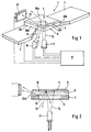
- the analysis element 1 shown in FIGS. 1 and 2 is designed as a test strip 2. It consists of one base strip 3 and made of rigid plastic a test field 4 attached to it shown case only a test layer 5, which with a Foil piece 6 is firmly connected.
- a drop of sample liquid is used to perform an analysis applied to the top 8 of the test layer 5.
- the liquid penetrates, dissolving the in the Test layer 5 contained reagents until they on the Bottom 9 of the test layer 5, the top 10 of the film piece 6 contacted.
- the reaction of the analyte contained in the sample leads to an optically measurable change, especially one Color change, the Teet Mrs 5.
- a light source 11 for example a light-emitting diode
- the evaluation device on the primary light 13 by a below of the test field 4 provided hole 12 of the base strip 3 directed to the underside 14 of the film piece 6 is.
- the test layer 5 through that Film piece 6 diffusely reflected by arrows 15 symbolized secondary light is from a light receiver 16 converted into measurement signals by an evaluation electronics 17 for information about the present or Concentration of the analyte in the sample processed become.
- a light receiver 22 is provided to detect light, which is also connected to the evaluation electronics 17 is. To distinguish it from the measuring receiver 16 he is hereinafter referred to as control recipient 22.
- the name for his light signal is below "Transverse signal” used while the signal of the Measuring receiver 16 is referred to as a "reflectance signal”.
- the control receiver 22 must be designed and arranged in this way be that it selectively detects secondary light that emerges from the peripheral surface 20.
- the evaluation device 23 shown in FIG. 3 has a test strip holder 24, through which the test strip 2 in a defined measuring position is held.
- a suitable one Test strip holder is for example in the US patent 5,424,035.
- the control recipient 22 is like this positioned that its photosensitive surface is dense is arranged at the peripheral surface 20.
- Appropriate means are provided to prevent interference from others Light sources, especially from scattered primary light or to minimize by ambient light. This can be done in a known way Way by means of screens, light barriers and one closing the analysis element holder 24 in a light-tight manner Cover happen. It may also be appropriate to use frequency modulation Primary light and one on the modulation frequency to use a coordinated detection method.
- test field shown in the figures - as general usual - has a rectangular shape, there is the peripheral surface 20 out of four each between the corners of the Rectangular partial areas 20a to 20d.
- a second control recipient is shown in broken lines in FIG 25 indicated, which is designed analogously to the control receiver 22 and on the opposite side of the test field 4 is positioned so that the two side Subareas 20a and 20c of the peripheral surface 20 of the Film piece 6 emerging light can be detected.
- the two are remaining (front and rear) partial surfaces of the peripheral surface not accessible because of a hot melt adhesive strip 26 are closed, for attachment of the test field 4 on the base strip 3.
- the peripheral surface 20 emerging light it can be advantageous be at least a part of the other partial areas 20b to 20d mirror the peripheral surface 20 so that the light reflected from the mirrored areas towards the control receiver 22 from the peripheral surface 20 exits.
- Fig. 4 shows the course of the light signal during the Absorbing the liquid into the test layer 5. Shown is the intensity I (tension of the amplified Signals in volts) as a function of time t (measured in seconds).
- the top dashed line shows the remission signal, i.e. that detected by the measuring receiver 16 Intensity of the diffusely reflected secondary light.
- the solid bottom line shows the transverse signal, d. H. the intensity of that from the control recipient 22 detected from the peripheral surface 20 emerging secondary light. Both light signals were amplified with identical amplifiers. Arrows 28 denote the time at which the surface of the test layer 5 has been contacted with the sample liquid.
- the intensity of the remission signal is twice as high like that of the transversal signal. For the measurement accuracy is however much more important that the relative signal change of the transverse signal much larger than that of the Remission signal is.
- the remission signal drops to Time of fluid intake so little (on average over five series of measurements by about 1.3%) that only large Difficulties can be reliably evaluated.
- the transversal signal increases during soaking up of the liquid in the test layer is essential stronger (about 5% on average over five measurements). This increase can be evaluated relatively easily and reliably become.
- the inventors should the effect on which the invention is based be that by wetting the test layer 5 and thus the top 10 of the film piece facing her 6 the conditions for decoupling light be changed from the piece of film. Part of that in that Film piece penetrating primary light 13 is (depending from the angle of incidence) at the interfaces of the film piece 6 totally reflected.
- the piece of film thus acts in the to some extent as a light guide.
- the totally reflected Light emerges at the peripheral surface 20 and can be as described can be detected.
- Fig. 5 correspond in all respects to Fig. 4 except that the test layer 5 not with blood but with distilled Water was contacted. While that is dashed represented remission signal only a small barely perceptible Burglary at the time of contacting the sample liquid shows is for the transversal signal in this case too, a clear, easily measurable Determine signal change. This shows that the Invention is particularly suitable in cases where which the sample liquid does not or only very weakly is colored.
- test layer 4 on that facing away from the light source 11 Positioned the piece of film 6, the Test layer is thus illuminated through the piece of film. It is not a problem if the in Contact to the film piece 6 standing test layer 5 one or several further layers are provided.
- the test field 4 can have three layers, the first of which to separate the red blood cells serves, the second contains a reagent, the one Pre-reaction causes and the third with the film piece 6 layer in contact is a color reaction layer which is the reagents required for the color reaction contains.
- the liquid their inclusion in the layer adjacent to the film piece to be checked not necessarily the original one Is sample liquid. Rather, it can one already changed by preparatory steps Sample liquid (especially to remove the red Blood cells from blood).
- An analysis element 30 is shown with Longitudinal liquid transport, in which on a base strip 3 at least several test layers 31 to 33 are partially arranged side by side so that one on the first test layer 31 on given sample liquid similar to a chromatography process along the Test layers (from left to right in the figure) in an evaluation zone is transported in which one for the Analysis required detection reaction takes place. Further details of such an analysis element type are described, for example, in US Pat. No. 5,110,550.
- the control of fluid intake also relates in this case the last test layer in the direction of flow.
- the flow path of the liquid ends at the in the figure right end of the test layer 32.
- the reference number 34 denotes a hot melt adhesive strip, by means of a transparent film piece 35 is attached, the relatively stiff, so that the right part of the Test layer 32 and the test layer located below 33 are held down by the film piece 35.
- the film piece 35 is therefore also used as a hold-down layer designated.
- This is an example of that the invention is also suitable in cases where the required Contact between the test layer 33 and the film piece 35 not by coating or any other immediate Connection, but in other ways, for example with an adhesive strip provided on the edge, will be produced.
Abstract
Description
Die Erfindung betrifft ein Verfahren zur Kontrolle der Flüssigkeitsaufnahme einer Testschicht eines Analyseelementes sowie ein entsprechendes Analysesystem bestehend aus Analyseelementen und einem zu deren Auswertung ausgebildeten Auswertegerät.The invention relates to a method for controlling the Liquid absorption of a test layer of an analysis element as well as a corresponding analysis system from analysis elements and one designed for their evaluation Evaluation device.
Zur qualitativen und quantitativen Analyse von Bestandteilen einer flüssigen Probe, insbesondere einer Körperflüssigkeit von Menschen oder Tieren, werden in großem Umfang sogenannte trägergebundene Tests eingesetzt. Dabei werden Analyseelemente verwendet, bei denen Reagenzien in eine oder mehrere Testschichten eingebettet sind. Zur Durchführung einer Reaktion wird das Analyseelement mit der Probe in Kontakt gebracht. Die Reaktion von Probe und Reagenz führt zu einer visuell oder mit Hilfe eines Auswertegerätes (meistens reflexionsphotometrisch) auswertbaren für die Analyse charakteristischen Veränderung des Analyseelementes. For the qualitative and quantitative analysis of components a liquid sample, especially a body fluid of humans or animals, become large Scope of so-called carrier-related tests used. Here analysis elements are used in which reagents in one or more test layers are embedded. For Carrying out a reaction is using the analysis element the sample in contact. The reaction of sample and Reagent leads to a visual or with the help of an evaluation device (mostly reflection photometric) evaluable characteristic change for the analysis of the Analysis element.
Das Auswertegerät ist in der Regel zur Auswertung eines ganz bestimmten Typs von Analyseelementen eines bestimmten Herstellers geeignet. Die Analyseelemente und das Auswertegerät bilden dabei wechselseitig aufeinander abgestimmte Bestandteile und werden üblicherweise insgesamt als Analysesystem bezeichnet.The evaluation device is usually used to evaluate a very specific type of analytical elements of a particular Manufacturer suitable. The analysis elements and that Evaluation devices form mutually coordinated devices Ingredients and are usually total referred to as an analysis system.
Es sind zahlreiche unterschiedliche Analyseelement-Typen bekannt, die sich durch das Meßprinzip (z.B. optisch oder elektrochemisch) und die verwendeten Reagenzien sowie durch ihren Aufbau, insbesondere durch die Anordnung und Befestigung der Testschichten, unterscheiden. Gebräuchlich sind insbesondere streifenförmige Analyseelemente (Teststreifen), die aus einem länglichen Kunststoffstreifen ("Basisstreifen") und mindestens einer daran befestigten Testschicht bestehen. Bei einem anderen gebräuchlichen Analyseelementtyp wird ein Kunststoffrahmen ähnlich einem photographischen Diapositiv verwendet, in dem mindestens eine Testschicht eingerahmt ist.There are numerous different types of analysis elements known, which is characterized by the measuring principle (e.g. optical or electrochemical) and the reagents used as well by their structure, in particular by the arrangement and Fasten the test layers, differentiate. Common are in particular strip-shaped analysis elements (Test strips) made from an elongated plastic strip ("Base strip") and at least one attached to it Test layer exist. Another common one The analysis element type is similar to a plastic frame a photographic slide in which at least one test layer is framed.
Die Testschichten bestehen aus einem saugfähigen Material, wie beispielsweise Papier oder porösem Kunststoff. Wenn sie zur Durchführung einer Analyse mit der Probenflüssigkeit in Kontakt gebracht werden, saugen sie Flüssigkeit in sich auf. Für eine korrekte Analyse ist es wichtig, daß diese Flüssigkeitsaufnahme gleichmäßig und vollständig erfolgt. Bei jedem Test soll die gleiche, dem Saugvermögen der Testschicht entsprechende Flüssigkeitsmenge aufgesaugt und gleichmäßig in der Testschicht verteilt werden.The test layers are made of an absorbent material, such as paper or porous plastic. If you are performing an analysis on the sample liquid brought into contact, they suck liquid in itself. For a correct analysis it is important that this fluid intake is even and completely done. Every test should be the same, the Suction rate of the test layer corresponding amount of liquid absorbed and evenly distributed in the test layer become.
Eine visuelle Kontrolle der Flüssigkeitsaufnahme durch den Benutzer ist wenig zuverlässig. Dies gilt insbesondere für Analyseelemente zur Kontrolle des Blutzuckerspiegels, die von Diabetikern benutzt werden, deren Sehvermögen häufig durch die Krankheit beeinträchtigt ist. Es sind deshalb bereits zahlreiche Vorschläge gemacht worden, die Flüssigkeitsaufnahme von Testschichten apparativ mittels eines durch das Auswertegerät durchgeführten Meßverfahrens zu kontrollieren.A visual check of fluid intake the user is unreliable. This is especially true for analytical elements to control blood sugar levels, that are used by diabetics, their eyesight is often affected by the disease. Therefore, numerous suggestions have already been made been liquid absorption of test layers by apparatus by means of one carried out by the evaluation device Control measuring method.
Beispielsweise ist in der EP-0087466 ein Analysesystem beschrieben, bei dem aufgrund der optischen Absorption von Wasser im Infrarotbereich eine Abschätzung der von einer Testschicht aufgesaugten Probenmenge vorgenommen wird. Um ein für die Flüssigkeitsaufnahme charakteristisches Lichtsignal zu erzeugen, wird dabei die Testschicht mit Primärlicht (Infrarotlicht mit einer Wellenlänge von etwa 2 µm) beleuchtet und das dabei von der Testschicht diffus reflektierte Sekundärlicht mittels eines Lichtempfängers detektiert. Die Intensität des reflektierten Lichts wird sowohl im trockenen Zustand des Analyseelementes als auch nach der Kontaktierung mit der Probe bestimmt. Um eine Information über die in die Testschicht aufgesaugte Flüssigkeitsmenge zu gewinnen, wird die Differenz dieser beiden Lichtsignale mit einem Referenzsignal verglichen.For example, EP-0087466 contains an analysis system described in which due to the optical absorption of water in the infrared range an estimate of made of a sample layer becomes. A characteristic of fluid intake The test layer is used to generate a light signal with primary light (infrared light with a wavelength of about 2 µm) and that from the test layer diffusely reflected secondary light by means of a light receiver detected. The intensity of the reflected Light is both in the dry state of the analysis element as well as after contacting the sample. To provide information about that in the test layer Gaining the amount of liquid absorbed becomes the difference of these two light signals with a reference signal compared.
Weitere vorbekannte Verfahren zur Kontrolle der vollständigen Flüssigkeitsaufnahme einer Testschicht mittels des entsprechenden Auswertegerätes sind in der EP 0473241 A2, dem US-Patent 5,114,350 und der DE 19628562 A1 beschrieben. Gemeinsam ist diesen vorbekannten Verfahren, daß die Oberfläche der Testschicht mit Primärlicht beleuchtet und dabei die Intensität des von der Testschicht diffus reflektierten Lichts mittels eines auf deren Oberfläche gerichteten Detektors während des Aufsaugens der Flüssigkeit in die Schicht beobachtet wird. Die in die Testschicht eindringende Flüssigkeit führt zu einer Verminderung der diffus reflektierten Intensität. Zeitpunkt und Ausmaß der Intensitätsänderung des diffus reflektierten Lichtes werden verwendet, um Informationen über Zeitpunkt und Vollständigkeit der Flüssigkeitsaufnahme in die Testschicht zu gewinnen.Other known methods for checking the complete Liquid absorption of a test layer using the corresponding evaluation device are in EP 0473241 A2, U.S. Patent 5,114,350 and DE 19628562 A1. Common to these previously known processes is that the Surface of the test layer illuminated with primary light and the intensity of that diffusely reflected by the test layer Light by means of one directed at its surface Detector while absorbing the liquid is observed in the layer. The one in the test layer penetrating liquid leads to a decrease the diffusely reflected intensity. Time and Extent of the change in intensity of the diffusely reflected Light are used to provide information about when and completeness of the liquid absorption in the test layer to win.
Dieses vorbekannte Meßprinzip hat jedoch erhebliche Nachteile. Insbesondere ist die Größe der Signaländerung bei der Flüssigkeitsaufnahme stark von der optischen Absorption der Flüssigkeit bei der Meßwellenlänge des Primärlichts abhängig. Im Spektralbereich des sichtbaren Lichts ergibt sich deshalb nur bei stark gefärbten Flüssigkeiten, wie beispielsweise Vollblut, eine gut meßbare starke Signaländerung. Wenn hingegen die in die Testschicht aufgesaugte Flüssigkeit im sichtbaren Spektrum nur sehr schwach gefärbt ist (wie beispielsweise Serum oder Urin) ist die Signaländerung sehr gering und deswegen die Kontrolle der Flüssigkeitsaufnahme unzuverlässig. Insbesondere ist sie empfindlich gegen Störeinflüsse, beispielsweise eine geringfügige Änderung der Testschichtposition durch versehentliches Berühren des Analyseelementes in dem Auswertegerät.However, this known measuring principle has considerable disadvantages. In particular, the size of the signal change is at the fluid intake greatly depends on the optical absorption of the liquid at the measuring wavelength of the primary light dependent. In the spectral range of visible light therefore only arises with strongly colored liquids, such as whole blood, a well measurable strong Signal change. If, on the other hand, the one absorbed into the test layer Liquid in the visible spectrum only very much is weakly colored (such as serum or urine) the signal change is very small and therefore the control fluid intake unreliable. In particular it is sensitive to interference, for example a slight change in the test layer position by accidentally touching the analysis element in the evaluation device.
Der Erfindung liegt auf dieser Basis die Aufgabe zugrunde, ein Verfahren und eine Vorrichtung zur Kontrolle der Flüssigkeitsaufnahme einer Testschicht zur Verfügung zu stellen, daß sich durch eine verbesserte Zuverlässigkeit auszeichnet.On this basis, the invention is based on the object a method and device for control the liquid absorption of a test layer to provide that through improved reliability distinguished.
Die Aufgabe wird durch ein Verfahren gemäß Anspruch 1 und
ein Analysesystem gemäß Anspruch 5 gelöst. Bevorzugte
Ausgestaltungen sind Gegenstand der Unteransprüche. The object is achieved by a method according to
Es ist eine Vielzahl unterschiedlicher Typen von Analyseelementen bekannt, bei denen die Erfindung vorteilhaft verwendet werden kann.
- Weit verbreitet sind Analyseelemente, bei denen eine Mehrzahl von Testschichten derartig übereinander angeordnet sind, daß ihre Oberflächen in einen Flüssigkeitsaustausch ermöglichendem Kontakt zueinander stehen. Die Gesamtheit der übereinandergestapelten Testschichten wird als "Testfeld" bezeichnet. Die Probenflüssigkeit wird üblicherweise auf die oberste Schicht des Testfeldes aufgegeben und dringt nach und nach in die darunterliegenden Testschichten ein, bis schließlich die unterste Schicht die Flüssigkeit in sich aufsaugt. Da bei solchen Analyseelementen die Flüssigkeitsausbreitung im wesentlichen quer zur Flächenausdehnung der Testschichten erfolgt, werden sie als "Analyseelemente mit Flüssigkeits-Quertransport" bezeichnet.
- Daneben gibt es "Analyseelemente mit FlüssigkeitsLängstransport", bei denen mehrere Testschichten - üblicherweise auf einem Basisstreifen - unmittelbar nebeneinander angeordnet sind, wobei sie am Rand so in Kontakt zueinander stehen, daß ein Flüssigkeitsübertritt von Testschicht zu Testschicht parallel zu deren Flächenausdehnung möglich ist.
- Schließlich sind Kombinationen dieser beiden Prinzipien bekannt, wie sie beispielsweise in der US-Patentschrift 5,096,836 beschrieben sind.
- Analysis elements are widely used, in which a plurality of test layers are arranged one above the other in such a way that their surfaces are in contact with one another to enable liquid exchange. The entirety of the stacked test layers is referred to as a "test field". The sample liquid is usually applied to the top layer of the test field and gradually penetrates into the test layers underneath until the bottom layer finally absorbs the liquid. Since in such analysis elements the liquid spread essentially takes place transversely to the surface area of the test layers, they are referred to as "analysis elements with liquid cross transport".
- In addition, there are "analysis elements with longitudinal liquid transport", in which several test layers - usually on a base strip - are arranged directly next to each other, where they are in contact with each other at the edge so that a liquid transfer from test layer to test layer is possible parallel to their surface area.
- Finally, combinations of these two principles are known, as described, for example, in US Pat. No. 5,096,836.
Die Kontrolle der Flüssigkeitsaufnahme bezieht sich in der Regel auf die in dem Strömungsweg der Flüssigkeit letzte Testschicht des Analyseelementes. Grundsätzlich ist die Erfindung jedoch zur Kontrolle der Flüssigkeitsaufnahme jeder beliebigen saugfähigen Testschicht eines Analyseelementes geeignet, sofern diese Testschicht in unmittelbarem Kontakt mit einem optisch transparenten Folienstück steht. Der Begriff "saugfähig" ist dabei allgemein als Bezeichnung für jede Form der Flüssigkeitsaufnahme zu verstehen und umfaßt nicht nur die durch Kapillarwirkung verursachte Saugfähigkeit poröser Materialien sondern auch die auf einem Quellvorgang basierende Flüssigkeitsaufnahme.The control of fluid intake relates to usually on the in the flow path of the liquid last test layer of the analysis element. Basically However, the invention is for controlling fluid intake any absorbent test layer one Suitable analysis element, provided that this test layer in direct contact with an optically transparent Foil piece stands. The term "absorbent" is general as a name for every form of fluid intake to understand and includes not only that by capillary action Absorbance caused by porous materials but also the fluid intake based on a swelling process.
Optisch transparente Kunststoffolien werden bei der Konstruktion von Analyseelementen vor allem als Testschichtträger in Fällen verwendet, bei denen die Testschicht mit dem Folienstück fest verbunden ist. Insbesondere kann das Folienstück, das eine Testschichtträgerfolie für die Testschicht bildet, mit der Testschicht unmittelbar beschichtet sein. Dies ist gebräuchlich bei Testschichten, die keine selbsttragenden Eigenschaften haben.Optically transparent plastic films are used in the construction of analysis elements especially as test layer supports used in cases where the test layer with the piece of film is firmly connected. In particular, it can Foil piece, which is a test layer carrier film for the Test layer forms, directly coated with the test layer his. This is common for test layers, that have no self-supporting properties.
Hierzu gehören insbesondere sogenannte Testfilme, also Testschichten, die durch Beschichtung eines Substrats mit einem dünnen Film eines filmbildenden Materials hergestellt werden. Bekannt sind insbesondere quellfähige Testfilme auf Basis von Gelatine sowie nichtquellende poröse Testfilme auf Basis eines Dispersionsfilmbildners. Die zur Flimbildung verwendete filmbildende Masse enthält neben den Reagenzien in der Regel feste Bestandteile, wie insbesondere Pigmente und Kieselgur, die der Schicht die gewünschte Opazität und Saugfähigkeit verleihen. Besonders bewährt hat sich die Erfindung bei Testschichten, die einen Dispersionsfilmbildner und ein Pigment enthalten. Derartige Testschichten sind beispielsweise in den US-Patenten 5,169,787 und 5,536,470 beschrieben. This includes, in particular, so-called test films Test layers by coating a substrate with a thin film of a film-forming material become. Swellable in particular are known Test films based on gelatin and non-swelling porous Test films based on a dispersion film former. The film-forming mass used for film formation contains in addition to the reagents usually solid components, such as especially pigments and diatomaceous earth, which the layer Give desired opacity and absorbency. Especially The invention has proven itself in test layers, which contain a dispersion film former and a pigment. Such test layers are for example in the U.S. Patents 5,169,787 and 5,536,470.
Die in Analyseelementen (insbesondere als Testschichtträgerfolie) verwendeten transparenten Folien, haben eine sehr geringe Dicke von meist weniger als 0,2 mm. Dementsprechend ist die Flächenausdehnung der Umfangsfläche (d.h. der senkrecht zu der Flächenausdehnung der Folie an deren Umfang verlaufenden Schnittfläche) sehr gering. Beispielsweise besteht bei einem quadratischen Folienstück von 6 mm Kantenlänge die Umfangsfläche aus vier Teilabschnitten, die jeweils eine Fläche von nur 1,2 mm2 haben. Dagegen haben die Hauptflächen (Oberseite und die Unterseite) jeweils eine Flächenausdehnung von 36 mm2. Obwohl der Austrittsquerschnitt für Licht aus der Umfangsfläche sehr gering ist, wurde im Rahmen der Erfindung festgestellt, daß das aus der Umfangsfläche austretende Licht eine so hohe Intensität hat, daß es ohne besondere Probleme gemessen werden kann.The transparent foils used in analysis elements (especially as test layer carrier foils) have a very small thickness of usually less than 0.2 mm. Accordingly, the surface area of the peripheral surface (ie the cut surface perpendicular to the surface area of the film on its circumference) is very small. For example, in the case of a square piece of film with an edge length of 6 mm, the peripheral surface consists of four sections, each of which has an area of only 1.2 mm 2 . In contrast, the main surfaces (top and bottom) each have an area of 36 mm 2 . Although the exit cross-section for light from the peripheral surface is very small, it was found in the context of the invention that the light emerging from the peripheral surface has such a high intensity that it can be measured without particular problems.
Besonders vorteilhaft ist, daß die prozentuale Änderung der aus der Umfangsfläche austretenden Lichtintensität während der Flüssigkeitsaufnahme wesentlich höher ist als die Intensitätsänderung des diffus reflektierten Lichts, das bei den vorbekannten Verfahren zur Kontrolle der Flüssigkeitsaufnahme detektiert wurde. Dies gilt insbesondere auch in Fällen, bei denen die von der Testschicht aufgesaugte Flüssigkeit eine geringe Färbung aufweist. Selbst mit destilliertem Wasser wird eine relativ starke Signaländerung beim Aufsaugen der Flüssigkeit in die Testschicht beobachtet. Deswegen läßt sich bei dem erfindungsgemäßen Verfahren mit einfachen Mitteln eine erhöhte Zuverlässigkeit der Kontrolle der Flüssigkeitsaufnahme erreichen. Das Verfahren ist sehr robust gegen Störungen, wie beispielsweise Änderungen des Primärlichts und Änderungen der Position des Analyseelementes in dem Auswertegerät, die durch versehentliches Berühren verursacht werden. It is particularly advantageous that the percentage change the light intensity emerging from the peripheral surface during fluid intake is significantly higher than the change in intensity of the diffusely reflected light, that in the previously known methods for controlling the Fluid intake was detected. This is especially true even in cases where the test layer absorbed liquid has a slight color. Even with distilled water it becomes a relatively strong one Signal change when the liquid is sucked into the Test layer observed. Therefore can be in the inventive Procedure with simple means an increased Reliability of control of fluid intake to reach. The process is very robust against interference, such as changes in primary light and changes the position of the analysis element in the evaluation device, caused by accidental touch.
Mit dem erfindungsgemäßen Verfahren wird gezielt die Benetzung der Grenzschicht zwischen der Testschicht und dem Folienstück detektiert. Die vollständige Flüssigkeitsaufnahme wird deshalb zuverlässiger als bei den vorbekannten Verfahren bestimmt, bei denen sich das Meßsignal auf den Mittelwert des Testschichtvolumens bezieht.With the method according to the invention, wetting is targeted the boundary layer between the test layer and the Film piece detected. Complete fluid intake is therefore more reliable than the previously known Determines methods in which the measurement signal on the Average value of the test layer volume.
Die Erfindung wird nachfolgend anhand von in den Figuren schematisch dargestellten Ausführungsbeispielen näher erläutert; es zeigen:
- Fig. 1
- eine perspektivische Prinzipdarstellung der für die Erfindung wesentlichen Elemente eines Analysesystems,
- Fig. 2
- eine Seitenansicht, teilweise im Schnitt, entsprechend Fig. 1,
- Fig. 3
- eine perspektivische Darstellung eines Teils eines Auswertegerätes in dessen Analyseelementhalterung sich ein Analyseelement in der Meßposition befindet,
- Fig. 4
- Meßkurven bei der Kontrolle der Flüssigkeitsaufnahme eines Analyseelementes mit Blut als Probenflüssigkeit,
- Fig. 5
- Meßkurven bei der Kontrolle der Flüssigkeitsaufnahme eines Analyseelementes mit Wasser als Probenflüssigkeit,
- Fig. 6
- eine perspektivische Prinzipdarstellung einer bevorzugten Ausführungsform zur Flüssigkeitskontrolle bei einem Testträger mit Längstransport.
- Fig. 1
- 2 shows a perspective illustration of the essential elements of an analysis system for the invention,
- Fig. 2
- a side view, partially in section, corresponding to Fig. 1,
- Fig. 3
- 1 shows a perspective illustration of a part of an evaluation device in the analysis element holder of which an analysis element is in the measurement position,
- Fig. 4
- Measurement curves when checking the liquid absorption of an analysis element with blood as sample liquid,
- Fig. 5
- Measurement curves when checking the liquid absorption of an analysis element with water as sample liquid,
- Fig. 6
- a perspective schematic representation of a preferred embodiment for liquid control in a test carrier with longitudinal transport.
Das in den Figuren 1 und 2 dargestellte Analyseelement 1
ist als Teststreifen 2 ausgebildet. Er besteht aus einem
aus steifem Kunststoff hergestelltem Basisstreifen 3 und
einem daran befestigten Testfeld 4. Das Testfeld 4 hat im
dargestellten Fall nur eine Testschicht 5, die mit einem
Folienstück 6 fest verbunden ist.The
Zur Durchführung einer Analyse wird ein Tropfen Probenflüssigkeit
auf die Oberseite 8 der Testschicht 5 aufgebracht.
Die Flüssigkeit dringt unter Auflösung der in der
Testschicht 5 enthaltenen Reagenzien ein, bis sie an der
Unterseite 9 der Testschicht 5 die Oberseite 10 des Folienstücks
6 kontaktiert.A drop of sample liquid is used to perform an analysis
applied to the
Die Reaktion des in der Probe enthaltenen Analyten führt
zu einer optisch meßbaren Änderung, insbesondere einer
Farbänderung, der Teetschicht 5. Um diese zu messen weist
das Auswertegerät eine Lichtquelle 11, beispielsweise
eine Leuchtdiode, auf deren Primärlicht 13 durch ein unterhalb
des Testfeldes 4 vorgesehenes Loch 12 des Basisstreifens
3 auf die Unterseite 14 des Folienstücks 6 gerichtet
ist. Das dabei von der Testschicht 5 durch das
Folienstück 6 diffus reflektierte durch die Pfeile 15
symbolisierte Sekundärlicht wird von einem Lichtempfänger
16 in Meßsignale umgewandelt, die von einer Auswerteelektronik
17 zu einer Information über die Gegenwart oder
Konzentration des Analyten in der Probe weiterverarbeitet
werden.The reaction of the analyte contained in the sample leads
to an optically measurable change, especially one
Color change, the
Insoweit ist das dargestellte Analysesystem und das Meßverfahren
konventionell. Die Kontrolle der Lichtquelle 11
und die Auswertung der Messung erfolgt in bekannter Weise
mit Hilfe der üblicherweise mit einem Mikroprozessor arbeitenden
Auswerteelektronik 17.In this respect, the analysis system shown and the measuring method
conventional. Checking the
Um aus der Umfangsfläche 20 des Folienstücks 6 austretendes
in den Figuren mit den Pfeilen 21 symbolisiertes
Licht zu detektieren ist ein Lichtempfänger 22 vorgesehen,
der ebenfalls an die Auswerteelektronik 17 angeschlossen
ist. Zur Unterscheidung von dem Meßempfänger 16
wird er nachfolgend als Kontrollempfänger 22 bezeichnet.
Für sein Lichtsignal wird nachfolgend die Bezeichnung
"Transversalsignal" verwendet, während das Signal des
Meßempfängers 16 als "Remissionssignal" bezeichnet wird.To emerge from the
Der Kontrollempfänger 22 muß so ausgebildet und angeordnet
sein, daß er selektiv Sekundärlicht detektiert, das
aus der Umfangsfläche 20 austritt. Ein Beispiel, wie dies
mit einfachen Mitteln erreicht werden, ist in Fig. 3.
dargestellt.The
Das in Fig. 3 gezeigte Auswertegerät 23 hat eine Teststreifenhalterung
24, durch die der Teststreifen 2 in einer
definierten Meßposition gehalten wird. Eine geeignete
Teststreifenhalterung ist beispielsweise in dem US Patent
5,424,035 beschrieben. Der Kontrollempfänger 22 ist so
positioniert, daß seine lichtempfindliche Fläche dicht
bei der Umfangsfläche 20 angeordnet ist. Außerdem sind
geeignete Mittel vorgesehen, um Störungen durch andere
Lichtquellen, insbesondere durch gestreutes Primärlicht
oder durch Umgebungslicht zu minimieren. Dies kann in bekannter
Weise mittels Blenden, Lichtsperrwänden und eines
die Analyseelementhalterung 24 lichtdicht verschließenden
Deckels geschehen. Außerdem kann es zweckmäßig sein, frequenzmoduliertes
Primärlicht und ein auf die Modulationsfrequenz
abgestimmtes Detektionsverfahren zu verwenden.The
Da das in den Figuren dargestellte Testfeld - wie allgemein
üblich - eine rechteckige Form hat, besteht die Umfangsfläche
20 aus vier jeweils zwischen den Ecken des
Rechtecks verlaufenden Teilflächen 20a bis 20d. Um ein
möglichst großes Transversalsignal zu erzeugen, kann es
vorteilhaft sein, das in alle Raumrichtungen aus der Umfangsfläche
20 austretende Licht mittels mehrerer Kontrollempfänger
zu erfassen, die jeweils so angeordnet
sind, daß sie aus einer der Teilfläche 20a bis 20c der
Umfangsfläche 20 austretendes Sekundärlicht detektieren.
In Fig. 2 ist gestrichelt ein zweiter Kontrollempfänger
25 angedeutet, der analog zu dem Kontrollempfänger 22 gestaltet
und auf der gegenüberliegenden Seite des Testfelds
4 positioniert ist, so daß das aus den beiden seitlichen
Teilflächen 20a und 20c der Umfangsfläche 20 des
Folienstücks 6 austretende Licht detektiert werden kann.
Bei dem dargestellten Teststreifentyp sind die beiden
verbleibenden (vorderen und hinteren) Teilflächen der Umfangsfläche
nicht zugänglich, weil sie von einem Schmelzkleberstreifen
26 verschlossen sind, der zur Befestigung
des Testfelds 4 an dem Basisstreifen 3 dient.As the test field shown in the figures - as general
usual - has a rectangular shape, there is the
Zur Erhöhung der Intensität des aus einer Teilfläche 20a
der Umfangsfläche 20 austretenden Lichts kann es vorteilhaft
sein, mindestens einen Teil der weiteren Teilflächen
20b bis 20d der Umfangsfläche 20 zu verspiegeln, so daß
das von den verspiegelten Teilflächen reflektierte Licht
in Richtung auf den Kontrollempfänger 22 aus der Umfangsfläche
20 austritt.To increase the intensity of a
Die nachfolgenden experimentellen Ergebnisse wurden mit
der in Fig. 3 dargestellten Anordnung mit nur einem Kontrollempfänger
22 erzielt. Sie zeigen, daß sehr gute Ergebnisse
selbst dann erreicht werden, wenn nur das aus
einer der vier Teilflächen 20a bis 20d der Umfangsfläche
20 austretende Sekundärlicht zur Kontrolle der Flüssigkeitsaufnahme
verwendet wird.The following experimental results were made using
the arrangement shown in Fig. 3 with only one
Fig. 4 zeigt den Verlauf des Lichtsignals während des
Aufsaugens der Flüssigkeit in die Testschicht 5. Dargestellt
ist die Intensität I (Spannung des verstärkten
Signals in Volt) in Abhängigkeit von der Zeit t (gemessen
in Sekunden). Die obere gestrichelte Linie zeigt das Remissionssignal,
d.h. die von dem Meßempfänger 16 detektierte
Intensität des diffus reflektierten Sekundärlichts.
Die durchgezogene untere Linie zeigt das Transversalsignal,
d. h. die Intensität des von dem Kontrollempfänger
22 detektierten aus der Umfangsfläche 20
austretenden Sekundärlichts. Beide Lichtsignale wurden
mit identischen Verstärkern verstärkt. Die Pfeile 28 bezeichnen
den Zeitpunkt, zu dem die Oberfläche der Testschicht
5 mit der Probenflüssigkeit kontaktiert wurde.Fig. 4 shows the course of the light signal during the
Absorbing the liquid into the
Die Intensität des Remissionssignals ist doppelt so hoch
wie die des Transversalsignal. Für die Meßgenauigkeit ist
jedoch wesentlich wichtiger, daß die relative Signaländerung
des Transversalsignals wesentlich größer als die des
Remissionssignals ist. Das Remissionssignal fällt zum
Zeitpunkt der Flüssigkeitsaufnahme so wenig (im Mittel
über fünf Meßreihen um etwa 1,3 %) daß es nur mit großen
Schwierigkeiten zuverlässig ausgewertet werden kann. Demgegenüber
steigt das Transversalsignal während des Aufsaugens
der Flüssigkeit in die Testschicht wesentlich
stärker (im Mittel über fünf Messungen um etwa 5 %) an.
Dieser Anstieg kann relativ leicht und zuverlässig ausgewertet
werden. Insbesondere kann es zweckmäßig sein, den
zeitlichen Verlauf des Lichtsignals mit einem in der Auswerteelektronik
17 enthaltenen Differenzierer zu differenzieren
und dadurch die Signaländerung zuverlässig zu
erkennen. Es kann auch vorteilhaft sein, das von dem Kontrollempfänger
22 empfangene Transversalsignal in Beziehung
zu dem Remissionssignal des Meßempfängers 16 zu setzen
und den Quotienten oder die Differenz beider Signale
der weiteren Auswertung bei der Kontrolle der Flüssigkeitsaufnahme
zugrundezulegen. The intensity of the remission signal is twice as high
like that of the transversal signal. For the measurement accuracy is
however much more important that the relative signal change
of the transverse signal much larger than that of the
Remission signal is. The remission signal drops to
Time of fluid intake so little (on average
over five series of measurements by about 1.3%) that only large
Difficulties can be reliably evaluated. In contrast
the transversal signal increases during soaking up
of the liquid in the test layer is essential
stronger (about 5% on average over five measurements).
This increase can be evaluated relatively easily and reliably
become. In particular, it may be appropriate to
temporal course of the light signal with one in the
Nach dem gegenwärtigen Kenntnisstand der Erfinder dürfte
der der Erfindung zugrundeliegende Effekt darauf zurückzuführen
sein, daß durch die Benetzung der Testschicht 5
und damit der ihr zugewandten Oberseite 10 des Folienstücks
6 die Bedingungen für die Auskopplung von Licht
aus dem Folienstück verändert werden. Ein Teil des in das
Folienstück eindringenden Primärlichts 13 wird (abhängig
von dem Einfallswinkel) an den Grenzflächen des Folienstücks
6 totalreflektiert. Das Folienstück wirkt somit im
gewissen Umfang als Lichtleiter. Das total-reflektierte
Licht tritt an der Umfangsfläche 20 aus und kann wie beschrieben
detektiert werden.According to the current state of knowledge, the inventors should
the effect on which the invention is based
be that by wetting the
Die in Fig. 5 dargestellten experimentellen Ergebnisse
entsprechen in jeder Hinsicht Fig. 4 mit der Ausnahme,
daß die Testschicht 5 nicht mit Blut sondern mit destilliertem
Wasser kontaktiert wurde. Während das gestrichelt
dargestellt Remissionssignal nur einen kleinen kaum wahrnehmbaren
Einbruch zum Zeitpunkt der Kontaktierung mit
der Probenflüssigkeit zeigt, ist für das Transversalsignal
auch in diesem Fall eine deutliche, gut meßbare
Signaländerung festzustellen. Dies zeigt, daß sich die
Erfindung in besonderem Maße auch in Fällen eignet, bei
denen die Probenflüssigkeit nicht oder nur sehr schwach
gefärbt ist.The experimental results shown in Fig. 5
correspond in all respects to Fig. 4 except
that the
Bei der in den Figuren 1 bis 3 dargestellten Anordnung
ist die Testschicht 4 auf der von der Lichtquelle 11 abgewandten
Seite des Folienstückes 6 positioniert, die
Testschicht wird somit durch das Folienstück hindurch beleuchtet.
Dabei ist es unproblematisch, wenn über der in
Kontakt zu dem Folienstück 6 stehenden Testschicht 5 eine
oder mehrere weitere Schichten vorgesehen sind. Beispielsweise
kann das Testfeld 4 drei Schichten aufweisen,
von denen die erste zur Abtrennung der roten Blutkörperchen
dient, die zweite eine Reagenz enthält, das eine
Vorreaktion bewirkt und die dritte mit dem Folienstück 6
in Kontakt stehende Schicht eine Farbreaktionsschicht
ist, die die für die Farbreaktion erforderlichen Reagenzien
enthält. Dieses Beispiel zeigt, daß die Flüssigkeit,
deren Aufnahme in die dem Folienstück benachbarte Schicht
kontrolliert werden soll, nicht notwendigerweise die ursprüngliche
Probenflüssigkeit ist. Vielmehr kann es sich
um eine durch Vorbereitungsschritte bereits veränderte
Probenflüssigkeit (speziell um durch Abtrennung der roten
Blutkörperchen aus Blut gewonnenes Plasma) handeln.In the arrangement shown in Figures 1 to 3
is the
Fig. 6 verdeutlicht weitere vorteilhafte Variationsmöglichkeiten.
Dargestellt ist ein Analyseelement 30 mit
Flüssigkeits-Längstransport, bei dem auf einem Basisstreifen
3 mehrere Testschichten 31 bis 33 zumindest
teilweise nebeneinander angeordnet sind, so daß eine auf
die erste Testschicht 31 auf gegebene Probenflüssigkeit
ähnlich wie bei einem Chromatographievorgang längs der
Testschichten (in der Figur von links nach rechts) in
eine Auswertezone transportiert wird, in der eine für die
Analyse erforderliche Nachweisreaktion stattfindet.
Nähere Einzelheiten eines solchen Analyseelementtyps sind
beispielsweise in dem US 5,110,550 beschrieben.6 illustrates further advantageous possible variations.
An
Die Kontrolle der Flüssigkeitsaufnahme bezieht sich auch
in diesem Fall auf die in Strömungsrichtung letzte Testschicht.
Der Strömungsweg der Flüssigkeit endet an dem in
der Figur rechten Ende der Testschicht 32. Die Bezugsziffer
34 bezeichnet einen Schmelzkleberstreifen, mittels
dessen ein transparentes Folienstück 35 befestigt ist,
das Verhältnismäßig steif ist, so daß der rechte Teil der
Testschicht 32 und die darunter befindliche Testschicht
33 durch das Folienstück 35 nach unten gehalten werden.
Das Folienstück 35 wird deshalb auch als Niederhalterschicht
bezeichnet. Dies ist ein Beispiel dafür, daß sich
die Erfindung auch in Fällen eignet, bei denen der erforderliche
Kontakt zwischen der Testschicht 33 und dem Folienstück
35 nicht durch Beschichten oder eine andere unmittelbare
Verbindung, sondern auf andere Weise, beispielsweise
durch einen am Rand vorgesehenen Klebestreifen,
hergestellt wird.The control of fluid intake also relates
in this case the last test layer in the direction of flow.
The flow path of the liquid ends at the in
the figure right end of the
Bei einem Analyseelement, bei dem die Flüssigkeit in einer,
in Fig. 6 durch den Pfeil 36 symbolisierten, definierten
Richtung parallel zu der Flächenausdehnung einer
Testschicht transportiert wird, ist es vorteilhaft, wenn
- wie dargestellt - die Lichtquelle auf einen Bereich der
Testschicht an deren in der Saugrichtung 36 hinterem Ende
gerichtet ist. Die Detektion des dabei aus der Umfangsfläche
22 austretenden Lichts erfolgt analog wie bei der
in Fig. 3 dargestellten Konstruktion mittels eines Kontrollichtempfängers
22.For an analytical element where the liquid is in a
6 symbolized, defined by the
Claims (10)
dadurch gekennzeichnet, daß
characterized in that
wobei die Testschicht (5,32) bei der Durchführung einer Analyse eine Flüssigkeit aufsaugt und das Auswertegerät (23) eine Auswerteelektronik (17) einschließt, um aus dem Verlauf des Lichtsignals während des Aufsaugens der Flüssigkeit eine Information über die Flüssigkeitsaufnahme zu gewinnen,
dadurch gekennzeichnet, daß
wherein the test layer (5, 32) absorbs a liquid when carrying out an analysis and the evaluation device (23) includes evaluation electronics (17) in order to obtain information about the liquid absorption from the course of the light signal while the liquid is being sucked up,
characterized in that
Applications Claiming Priority (2)
| Application Number | Priority Date | Filing Date | Title |
|---|---|---|---|
| DE19926931A DE19926931A1 (en) | 1999-06-14 | 1999-06-14 | Method and device for checking the liquid absorption of a test layer of an analysis element |
| DE19926931 | 1999-06-14 |
Publications (3)
| Publication Number | Publication Date |
|---|---|
| EP1061371A2 true EP1061371A2 (en) | 2000-12-20 |
| EP1061371A3 EP1061371A3 (en) | 2001-09-26 |
| EP1061371B1 EP1061371B1 (en) | 2008-07-02 |
Family
ID=7911092
Family Applications (1)
| Application Number | Title | Priority Date | Filing Date |
|---|---|---|---|
| EP00111467A Expired - Lifetime EP1061371B1 (en) | 1999-06-14 | 2000-05-27 | Method and device for controlling the liquid absorption of an analysing element test layer |
Country Status (5)
| Country | Link |
|---|---|
| US (1) | US6362890B1 (en) |
| EP (1) | EP1061371B1 (en) |
| JP (1) | JP2001004540A (en) |
| AT (1) | ATE399994T1 (en) |
| DE (2) | DE19926931A1 (en) |
Cited By (1)
| Publication number | Priority date | Publication date | Assignee | Title |
|---|---|---|---|---|
| EP1240503B1 (en) * | 1999-12-24 | 2018-01-17 | Roche Diabetes Care GmbH | Test strip analysis system, medical test strip, and method of analysing a sample by the help of a test strip analysis system |
Families Citing this family (13)
| Publication number | Priority date | Publication date | Assignee | Title |
|---|---|---|---|---|
| US6521182B1 (en) * | 1998-07-20 | 2003-02-18 | Lifescan, Inc. | Fluidic device for medical diagnostics |
| US6830934B1 (en) * | 1999-06-15 | 2004-12-14 | Lifescan, Inc. | Microdroplet dispensing for a medical diagnostic device |
| US20020140940A1 (en) * | 2001-02-28 | 2002-10-03 | Bambot Shabbir B. | System and method for measurement and analysis of a sample by absorption spectrophotometry |
| DE10164358C2 (en) * | 2001-12-28 | 2003-11-27 | Advalytix Ag | Characterization process for functionalized surfaces |
| US6731387B2 (en) * | 2002-02-06 | 2004-05-04 | Alexander V. Neimark | Light beam measurement of absorption by substrates |
| KR20030069486A (en) * | 2002-02-20 | 2003-08-27 | 엘지전자 주식회사 | Apparatus for optical analysis of test strip |
| DE10248555B4 (en) * | 2002-10-18 | 2004-12-02 | Roche Diagnostics Gmbh | Method and analysis system for determining the concentration of an analyte in a sample, which consists of the analyte and the sample matrix, and test element therefor |
| US7618591B2 (en) * | 2004-01-28 | 2009-11-17 | Bamburgh Marrsh Llc | Specimen sample collection device and test system |
| US20060000710A1 (en) * | 2004-06-30 | 2006-01-05 | Klaus Peter Weidenhaupt | Fluid handling methods |
| US20060002817A1 (en) * | 2004-06-30 | 2006-01-05 | Sebastian Bohm | Flow modulation devices |
| US20060001551A1 (en) * | 2004-06-30 | 2006-01-05 | Ulrich Kraft | Analyte monitoring system with wireless alarm |
| US20060000709A1 (en) * | 2004-06-30 | 2006-01-05 | Sebastian Bohm | Methods for modulation of flow in a flow pathway |
| EP1760469A1 (en) * | 2005-09-01 | 2007-03-07 | F.Hoffmann-La Roche Ag | Body fluid testing device with a rotating optical element |
Citations (5)
| Publication number | Priority date | Publication date | Assignee | Title |
|---|---|---|---|---|
| US5114350A (en) * | 1989-03-08 | 1992-05-19 | Cholestech Corporation | Controlled-volume assay apparatus |
| US5169787A (en) * | 1987-08-04 | 1992-12-08 | Boehringer Mannheim Gmbh | Test carrier for determining an analyte in a blood sample, process for making the carrier and use thereof |
| US5221958A (en) * | 1989-05-01 | 1993-06-22 | Wolfram Bohnenkamp | Reflection fluorometer |
| DE4407749A1 (en) * | 1993-03-09 | 1994-09-22 | Spectra Tech Inc | Method and apparatus for improving the use of infrared transmitting materials |
| US5563042A (en) * | 1986-08-13 | 1996-10-08 | Lifescan, Inc. | Whole blood glucose test strip |
Family Cites Families (13)
| Publication number | Priority date | Publication date | Assignee | Title |
|---|---|---|---|---|
| US3907503A (en) * | 1974-01-21 | 1975-09-23 | Miles Lab | Test system |
| DE3278024D1 (en) * | 1981-09-08 | 1988-02-25 | Eastman Kodak Co | Method and apparatus for detecting sample fluid |
| AU583040B2 (en) * | 1984-06-13 | 1989-04-20 | Applied Research Systems Ars Holding N.V. | Devices for use in chemical test procedures |
| DE3721237A1 (en) * | 1987-06-27 | 1989-01-05 | Boehringer Mannheim Gmbh | DIAGNOSTIC TEST CARRIER AND METHOD FOR THE PRODUCTION THEREOF |
| DE3844104A1 (en) | 1988-12-28 | 1990-07-05 | Boehringer Mannheim Gmbh | TEST CARRIER ANALYSIS SYSTEM |
| ATE137334T1 (en) * | 1991-02-28 | 1996-05-15 | Boehringer Mannheim Gmbh | TEST CARRIER FOR DETERMINING AN ANALYTE FROM WHOLE BLOOD |
| DE4227665A1 (en) * | 1992-08-21 | 1994-02-24 | Boehringer Mannheim Gmbh | Analysis element for the analysis of a liquid sample |
| DE4305058C2 (en) * | 1993-02-19 | 2001-04-12 | Roche Diagnostics Gmbh | Test carrier analysis system for analyzing a component of a liquid sample |
| DE4310583A1 (en) * | 1993-03-31 | 1994-10-06 | Boehringer Mannheim Gmbh | Test strip analysis system |
| DE4321548A1 (en) * | 1993-06-29 | 1995-01-12 | Boehringer Mannheim Gmbh | Method for acquiring and evaluating analog photometric signals in a test carrier analysis system and arrangement for carrying out the method |
| DE19628562A1 (en) * | 1996-07-16 | 1998-01-22 | Boehringer Mannheim Gmbh | Optical system evaluating quality of fluid distribution onto test piece, e.g. medical test strip |
| US6027459A (en) * | 1996-12-06 | 2000-02-22 | Abbott Laboratories | Method and apparatus for obtaining blood for diagnostic tests |
| US6084660A (en) * | 1998-07-20 | 2000-07-04 | Lifescan, Inc. | Initiation of an analytical measurement in blood |
-
1999
- 1999-06-14 DE DE19926931A patent/DE19926931A1/en not_active Withdrawn
-
2000
- 2000-05-27 DE DE50015232T patent/DE50015232D1/en not_active Expired - Fee Related
- 2000-05-27 EP EP00111467A patent/EP1061371B1/en not_active Expired - Lifetime
- 2000-05-27 AT AT00111467T patent/ATE399994T1/en not_active IP Right Cessation
- 2000-06-05 JP JP2000167508A patent/JP2001004540A/en not_active Ceased
- 2000-06-09 US US09/591,269 patent/US6362890B1/en not_active Expired - Fee Related
Patent Citations (5)
| Publication number | Priority date | Publication date | Assignee | Title |
|---|---|---|---|---|
| US5563042A (en) * | 1986-08-13 | 1996-10-08 | Lifescan, Inc. | Whole blood glucose test strip |
| US5169787A (en) * | 1987-08-04 | 1992-12-08 | Boehringer Mannheim Gmbh | Test carrier for determining an analyte in a blood sample, process for making the carrier and use thereof |
| US5114350A (en) * | 1989-03-08 | 1992-05-19 | Cholestech Corporation | Controlled-volume assay apparatus |
| US5221958A (en) * | 1989-05-01 | 1993-06-22 | Wolfram Bohnenkamp | Reflection fluorometer |
| DE4407749A1 (en) * | 1993-03-09 | 1994-09-22 | Spectra Tech Inc | Method and apparatus for improving the use of infrared transmitting materials |
Cited By (1)
| Publication number | Priority date | Publication date | Assignee | Title |
|---|---|---|---|---|
| EP1240503B1 (en) * | 1999-12-24 | 2018-01-17 | Roche Diabetes Care GmbH | Test strip analysis system, medical test strip, and method of analysing a sample by the help of a test strip analysis system |
Also Published As
| Publication number | Publication date |
|---|---|
| US6362890B1 (en) | 2002-03-26 |
| DE50015232D1 (en) | 2008-08-14 |
| JP2001004540A (en) | 2001-01-12 |
| EP1061371A3 (en) | 2001-09-26 |
| DE19926931A1 (en) | 2000-12-21 |
| ATE399994T1 (en) | 2008-07-15 |
| EP1061371B1 (en) | 2008-07-02 |
Similar Documents
| Publication | Publication Date | Title |
|---|---|---|
| EP1240503B1 (en) | Test strip analysis system, medical test strip, and method of analysing a sample by the help of a test strip analysis system | |
| EP1238274B1 (en) | Test element analysis system with infrared detector | |
| DE60018537T2 (en) | Test strip for the determination of an analyte in a liquid sample | |
| DE102004027131B4 (en) | Optical arrangement for assay reading device | |
| DE102004027132B4 (en) | Early determination of assay results | |
| DE2613617C2 (en) | Methods for analyzing samples, e.g. urine | |
| EP1117989B1 (en) | Method for the photometric analysis of test elements | |
| DE2723183C3 (en) | Test equipment for determining hemoglobin in a blood sample | |
| EP0105211B1 (en) | Cuvette for determining chemical compositions in liquids | |
| EP0821234B1 (en) | Diagnostic test element with multilayered test field and metod to assay analytes using it | |
| EP0376110B1 (en) | Test strip analysing system | |
| EP1061371B1 (en) | Method and device for controlling the liquid absorption of an analysing element test layer | |
| DE10163775A1 (en) | Analysis system for determining an analyte concentration taking into account sample and analyte-independent changes in light intensity | |
| EP0819943A2 (en) | Analysing system with means for detecting insufficient dose | |
| DE102004027130B4 (en) | Flow sampling for determination of assay results | |
| DE19544501A1 (en) | Device for light reflection measurements | |
| EP0309883B1 (en) | Test strip for the determination of an analyte in a body fluid | |
| EP1921441B1 (en) | Method for analysing a sample on a test element and analysis system | |
| DE10061336A1 (en) | System for the analysis of sample liquids including a position control unit | |
| EP2299899A1 (en) | Diagnostic tape unit and diagnostic measuring system | |
| EP1411346A2 (en) | Method for detection and compensation of the underdosage of test strips | |
| DE4314835A1 (en) | Method and device for analysing glucose in a biological matrix | |
| DE19628562A1 (en) | Optical system evaluating quality of fluid distribution onto test piece, e.g. medical test strip | |
| DE69636211T2 (en) | Process for the optical measurement of a liquid in a porous material | |
| DE202004008808U1 (en) | Instrument reading-out results of e.g. immuno assay, includes light sources and detectors to ensure velocity of fluid moving along porous lateral flow test strip lies within limits |
Legal Events
| Date | Code | Title | Description |
|---|---|---|---|
| PUAI | Public reference made under article 153(3) epc to a published international application that has entered the european phase |
Free format text: ORIGINAL CODE: 0009012 |
|
| 17P | Request for examination filed |
Effective date: 20000527 |
|
| AK | Designated contracting states |
Kind code of ref document: A2 Designated state(s): AT BE CH CY DE DK ES FI FR GB GR IE IT LI LU MC NL PT SE |
|
| AX | Request for extension of the european patent |
Free format text: AL;LT;LV;MK;RO;SI |
|
| RIN1 | Information on inventor provided before grant (corrected) |
Inventor name: RUPPENDER, UWE Inventor name: PETRICH, WOLFGANG, DR. Inventor name: VOELKEL,DIRK,DR. |
|
| PUAL | Search report despatched |
Free format text: ORIGINAL CODE: 0009013 |
|
| AK | Designated contracting states |
Kind code of ref document: A3 Designated state(s): AT BE CH CY DE DK ES FI FR GB GR IE IT LI LU MC NL PT SE |
|
| AX | Request for extension of the european patent |
Free format text: AL;LT;LV;MK;RO;SI |
|
| RIC1 | Information provided on ipc code assigned before grant |
Free format text: 7G 01N 35/00 A, 7G 01N 21/86 B, 7G 01N 21/55 B |
|
| AKX | Designation fees paid |
Free format text: AT BE CH CY DE DK ES FI FR GB GR IE IT LI LU MC NL PT SE |
|
| GRAP | Despatch of communication of intention to grant a patent |
Free format text: ORIGINAL CODE: EPIDOSNIGR1 |
|
| GRAS | Grant fee paid |
Free format text: ORIGINAL CODE: EPIDOSNIGR3 |
|
| GRAA | (expected) grant |
Free format text: ORIGINAL CODE: 0009210 |
|
| AK | Designated contracting states |
Kind code of ref document: B1 Designated state(s): AT BE CH CY DE DK ES FI FR GB GR IE IT LI LU MC NL PT SE |
|
| REG | Reference to a national code |
Ref country code: GB Ref legal event code: FG4D Free format text: NOT ENGLISH |
|
| REG | Reference to a national code |
Ref country code: CH Ref legal event code: EP |
|
| REF | Corresponds to: |
Ref document number: 50015232 Country of ref document: DE Date of ref document: 20080814 Kind code of ref document: P |
|
| REG | Reference to a national code |
Ref country code: IE Ref legal event code: FG4D Free format text: LANGUAGE OF EP DOCUMENT: GERMAN |
|
| PG25 | Lapsed in a contracting state [announced via postgrant information from national office to epo] |
Ref country code: NL Free format text: LAPSE BECAUSE OF FAILURE TO SUBMIT A TRANSLATION OF THE DESCRIPTION OR TO PAY THE FEE WITHIN THE PRESCRIBED TIME-LIMIT Effective date: 20080702 |
|
| NLV1 | Nl: lapsed or annulled due to failure to fulfill the requirements of art. 29p and 29m of the patents act | ||
| PG25 | Lapsed in a contracting state [announced via postgrant information from national office to epo] |
Ref country code: PT Free format text: LAPSE BECAUSE OF FAILURE TO SUBMIT A TRANSLATION OF THE DESCRIPTION OR TO PAY THE FEE WITHIN THE PRESCRIBED TIME-LIMIT Effective date: 20081202 Ref country code: ES Free format text: LAPSE BECAUSE OF FAILURE TO SUBMIT A TRANSLATION OF THE DESCRIPTION OR TO PAY THE FEE WITHIN THE PRESCRIBED TIME-LIMIT Effective date: 20081013 |
|
| REG | Reference to a national code |
Ref country code: IE Ref legal event code: FD4D |
|
| PG25 | Lapsed in a contracting state [announced via postgrant information from national office to epo] |
Ref country code: FI Free format text: LAPSE BECAUSE OF FAILURE TO SUBMIT A TRANSLATION OF THE DESCRIPTION OR TO PAY THE FEE WITHIN THE PRESCRIBED TIME-LIMIT Effective date: 20080702 |
|
| PG25 | Lapsed in a contracting state [announced via postgrant information from national office to epo] |
Ref country code: IE Free format text: LAPSE BECAUSE OF FAILURE TO SUBMIT A TRANSLATION OF THE DESCRIPTION OR TO PAY THE FEE WITHIN THE PRESCRIBED TIME-LIMIT Effective date: 20080702 Ref country code: DK Free format text: LAPSE BECAUSE OF FAILURE TO SUBMIT A TRANSLATION OF THE DESCRIPTION OR TO PAY THE FEE WITHIN THE PRESCRIBED TIME-LIMIT Effective date: 20080702 |
|
| PLBE | No opposition filed within time limit |
Free format text: ORIGINAL CODE: 0009261 |
|
| STAA | Information on the status of an ep patent application or granted ep patent |
Free format text: STATUS: NO OPPOSITION FILED WITHIN TIME LIMIT |
|
| 26N | No opposition filed |
Effective date: 20090403 |
|
| PG25 | Lapsed in a contracting state [announced via postgrant information from national office to epo] |
Ref country code: IT Free format text: LAPSE BECAUSE OF FAILURE TO SUBMIT A TRANSLATION OF THE DESCRIPTION OR TO PAY THE FEE WITHIN THE PRESCRIBED TIME-LIMIT Effective date: 20080702 |
|
| PGFP | Annual fee paid to national office [announced via postgrant information from national office to epo] |
Ref country code: DE Payment date: 20090529 Year of fee payment: 10 Ref country code: FR Payment date: 20090507 Year of fee payment: 10 |
|
| BERE | Be: lapsed |
Owner name: ROCHE DIAGNOSTICS G.M.B.H. Effective date: 20090531 |
|
| PGFP | Annual fee paid to national office [announced via postgrant information from national office to epo] |
Ref country code: GB Payment date: 20090407 Year of fee payment: 10 |
|
| PG25 | Lapsed in a contracting state [announced via postgrant information from national office to epo] |
Ref country code: MC Free format text: LAPSE BECAUSE OF NON-PAYMENT OF DUE FEES Effective date: 20090531 |
|
| REG | Reference to a national code |
Ref country code: CH Ref legal event code: PL |
|
| PG25 | Lapsed in a contracting state [announced via postgrant information from national office to epo] |
Ref country code: SE Free format text: LAPSE BECAUSE OF FAILURE TO SUBMIT A TRANSLATION OF THE DESCRIPTION OR TO PAY THE FEE WITHIN THE PRESCRIBED TIME-LIMIT Effective date: 20081002 Ref country code: CH Free format text: LAPSE BECAUSE OF NON-PAYMENT OF DUE FEES Effective date: 20090531 Ref country code: LI Free format text: LAPSE BECAUSE OF NON-PAYMENT OF DUE FEES Effective date: 20090531 |
|
| PG25 | Lapsed in a contracting state [announced via postgrant information from national office to epo] |
Ref country code: BE Free format text: LAPSE BECAUSE OF NON-PAYMENT OF DUE FEES Effective date: 20090531 |
|
| PG25 | Lapsed in a contracting state [announced via postgrant information from national office to epo] |
Ref country code: AT Free format text: LAPSE BECAUSE OF NON-PAYMENT OF DUE FEES Effective date: 20090527 |
|
| PG25 | Lapsed in a contracting state [announced via postgrant information from national office to epo] |
Ref country code: GR Free format text: LAPSE BECAUSE OF FAILURE TO SUBMIT A TRANSLATION OF THE DESCRIPTION OR TO PAY THE FEE WITHIN THE PRESCRIBED TIME-LIMIT Effective date: 20081003 |
|
| GBPC | Gb: european patent ceased through non-payment of renewal fee |
Effective date: 20100527 |
|
| REG | Reference to a national code |
Ref country code: FR Ref legal event code: ST Effective date: 20110131 |
|
| PG25 | Lapsed in a contracting state [announced via postgrant information from national office to epo] |
Ref country code: LU Free format text: LAPSE BECAUSE OF NON-PAYMENT OF DUE FEES Effective date: 20090527 Ref country code: DE Free format text: LAPSE BECAUSE OF NON-PAYMENT OF DUE FEES Effective date: 20101201 |
|
| PG25 | Lapsed in a contracting state [announced via postgrant information from national office to epo] |
Ref country code: FR Free format text: LAPSE BECAUSE OF NON-PAYMENT OF DUE FEES Effective date: 20100531 |
|
| PG25 | Lapsed in a contracting state [announced via postgrant information from national office to epo] |
Ref country code: GB Free format text: LAPSE BECAUSE OF NON-PAYMENT OF DUE FEES Effective date: 20100527 |
|
| PG25 | Lapsed in a contracting state [announced via postgrant information from national office to epo] |
Ref country code: CY Free format text: LAPSE BECAUSE OF FAILURE TO SUBMIT A TRANSLATION OF THE DESCRIPTION OR TO PAY THE FEE WITHIN THE PRESCRIBED TIME-LIMIT Effective date: 20080702 |