EP1061030A2 - Image forming apparatus with a device for inserting marker slips in the delivery pile - Google Patents
Image forming apparatus with a device for inserting marker slips in the delivery pile Download PDFInfo
- Publication number
- EP1061030A2 EP1061030A2 EP00305107A EP00305107A EP1061030A2 EP 1061030 A2 EP1061030 A2 EP 1061030A2 EP 00305107 A EP00305107 A EP 00305107A EP 00305107 A EP00305107 A EP 00305107A EP 1061030 A2 EP1061030 A2 EP 1061030A2
- Authority
- EP
- European Patent Office
- Prior art keywords
- user information
- tape
- address
- computer
- Prior art date
- Legal status (The legal status is an assumption and is not a legal conclusion. Google has not performed a legal analysis and makes no representation as to the accuracy of the status listed.)
- Withdrawn
Links
Images


Classifications
-
- B—PERFORMING OPERATIONS; TRANSPORTING
- B65—CONVEYING; PACKING; STORING; HANDLING THIN OR FILAMENTARY MATERIAL
- B65H—HANDLING THIN OR FILAMENTARY MATERIAL, e.g. SHEETS, WEBS, CABLES
- B65H33/00—Forming counted batches in delivery pile or stream of articles
- B65H33/04—Forming counted batches in delivery pile or stream of articles by inserting marker slips in pile or stream
-
- B—PERFORMING OPERATIONS; TRANSPORTING
- B65—CONVEYING; PACKING; STORING; HANDLING THIN OR FILAMENTARY MATERIAL
- B65H—HANDLING THIN OR FILAMENTARY MATERIAL, e.g. SHEETS, WEBS, CABLES
- B65H2301/00—Handling processes for sheets or webs
- B65H2301/40—Type of handling process
- B65H2301/42—Piling, depiling, handling piles
- B65H2301/426—Forming batches
- B65H2301/4261—Forming batches by inserting a wire or tape shaped marker element
- B65H2301/42612—Forming batches by inserting a wire or tape shaped marker element cut into tabs before or upon insertion
-
- B—PERFORMING OPERATIONS; TRANSPORTING
- B65—CONVEYING; PACKING; STORING; HANDLING THIN OR FILAMENTARY MATERIAL
- B65H—HANDLING THIN OR FILAMENTARY MATERIAL, e.g. SHEETS, WEBS, CABLES
- B65H2301/00—Handling processes for sheets or webs
- B65H2301/50—Auxiliary process performed during handling process
- B65H2301/51—Modifying a characteristic of handled material
- B65H2301/511—Processing surface of handled material upon transport or guiding thereof, e.g. cleaning
- B65H2301/5111—Printing; Marking
Definitions
- the present invention relates to an image forming apparatus of a stencil printer or the like having a tape sorter which is a simplified classifying apparatus, particularly to an image forming apparatus having a constitution in which computers of a plurality of users are connected to an image forming apparatus via a network and capable of easily identifying printed matters according to users when a plurality of users carry out printing of a large number of sheets in a large number of copies in the image forming apparatus.
- the tape sorter is provided at a paper discharge unit of an image forming apparatus such as a printer or the like.
- the tape sorter is used when users carry out printing of a large number of sheets in a large number of copies and for example, in determining breaks of a number of copies of printed matters, strips of tape are inserted by a unit of copy.
- an outputted printed matter is a printed matter having a plurality of pages, further time and labor is needed in search therefor.
- the present invention has been carried out in order to resolve the above-described problem and it is an object of the present invention to provide an image forming apparatus in which in a constitution in which computers of a plurality of users are connected to the image forming apparatus via a network and the respective users can easily determine printed matters of the users.
- an image forming apparatus comprising a printing section inputted with a print job from a computer via a network for forming an image of the print job on print paper, a paper discharge unit loaded with the print paper formed with the image, a classifying unit for classifying the print paper loaded at the paper discharge unit by inserting an identifier, means for acquiring user information of the computer outputting the print job on the network, and a recording unit for recording the acquired user information to the identifier.
- the user information may be inherent to the respective computer.
- the user information recorded to the identifier may be an address inherent to the computer detected on the network.
- the user information recorded to the identifier may be a name inherent to the computer detected on the network.
- a constitution further comprising storing means for previously storing an address of the respective computer and predetermined numerals, characters or signs in correspondence with the address, wherein the means for acquiring the user information detects the address inherent to the computer outputting the print job and records the predetermined numerals, characters or signs in correspondence with the address as the user information.
- the means for acquiring the user information is a controller for controlling transmission and reception of data on the network and the print job outputted from the respective computer, and the controller detects an address of the computer outputting the print job and outputs the predetermined numerals, characters or signs stored in correspondence with the address to the classifying unit as the user information.
- the means for acquiring the user information is a controller for controlling transmission and reception of data on the network and the print job outputted from the respective computer, the controller detects the address of the computer outputting the print job and outputs the address to the classifying unit, and the classifying unit records predetermined numerals, characters or signs stored in correspondence with the inputted address to the identifier as the user information.
- the classifying unit comprises a tape sorter comprising a feeding unit for inserting a tape strip having a predetermined length on a printed matter loaded at the paper discharge unit such that a portion of the tape strip is displayed as the identifier when the print job from the respective computer has been finished, and a recording unit for recording the user information on the displayed portion of the tape strip.
- the identifier is constituted by the print paper, further comprising means for recording the user information on the print paper as the identifier and shifting a position of loading the print paper as the identifier relative to other of the print paper such that the recorded portion is displayed.
- the recording unit comprises an ink jet head, a thermal head or the like for recording the user information.
- transmission and reception of data on the network and the print job are controlled by the controller and the address or characters or signs inherent to the computer is transmitted to the image forming apparatus as the user information.
- the image forming apparatus receives the user information and transmits the user information to the tape sorter which is the classifying apparatus every time of finishing the print job.
- the tape sorter records the address or the characters or signs in place thereof inherent to the computer as the user information on the tape, cuts the tape and mounts the cut tape at the uppermost portion of the printed matter.
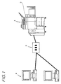
- FIG. 1 is a total constitution view showing a state in which an image forming apparatus is connected to a network.
- An explanation will be given of an example of a stencil printer having a tape sorter as a simplified classifying apparatus as follows.
- a tape sorter 2 is provided at a paper discharge unit of a stencil printer 1 shown in Fig. 1.
- the stencil printer 1 includes the tape sorter 2 and a controller 3.
- the stencil printer 1 comprises a perforating section for perforating a stencil sheet in an image-pattern, a printing section having a perforated stencil sheet wrapped thereon for rotationally printing a print paper, a paper feed mechanism and a paper transfer mechanism of print paper, and a paper discharge unit having discharged printed paper as printed matter loaded thereon.
- the paper discharge unit is provided with the tape sorter 2 for transmitting tape as an identifier in classifying printed matter loaded on a paper discharge base.
- the controller 3 is connected to computers (personal computers) 4 via a network of LAN or the like.
- computers personal computers
- a plurality of the computers 4 are provided on the network and are constructed by a constitution in which the stencil printer 1 can be used by a plurality of users.
- the computer 4 outputs print data of information of image intended to print as well as accompanying information of a number of sheets of printing, a number of copies and the like and the controller 3 acquires user information of the computer 4 and outputs the information to the stencil printer 1 along with the print data.
- tape sorter 2 The basic structure of the tape sorter is disclosed in Japanese Utility Model Laid-Open No. 45654/1989.
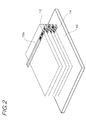
- Fig. 2 is a view showing a state of classifying printed matters by using the tape sorter 2. According to the drawing, among printed matters 12 discharged from the stencil printer 1 and loaded on the paper discharge base 10, tape strips 16a can be inserted by a unit of print job (a desired number of sheets and a desired number of copies).
- the user information is recorded on an end portion of the tape strip 16a and the user information is displayed out at a side position from an end face of the loaded printed matters. Thereby, even in a state loaded with the printed matters 12, the user information can be visually recognized.
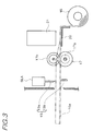
- Fig. 3 is a front view showing a constitution of the tape sorter and Fig. 4 is a plane view thereof.
- a pair of rollers 17 for transferring a tape 16 in a roll-like shape is constituted by a capstan roller 17a formed with a groove in a V-like shape at its peripheral face and a pinch roller 17b a peripheral edge portion of which is sharpened and opposed to the groove.
- a rotating shaft of the capstan roller 17a is connected with a motor M via a gear 18 and the tape 16 is sandwiched by the capstan roller 17a and the pinch roller 17b and the tape 16 is fed by a predetermined amount while being reeled out from the roll and bent in a V-like shape in its section.
- a cutter device 19 for cutting the tape 16 fed by the predetermined amount is provided frontward from the pair of rollers 17 for feeding the tape.
- the cutter device 19 is constituted by a movable blade 19a and a fixed blade 19b provided at a position supporting the transferred tape 16 and opposed to the movable blade 19a. After finishing transfer of the tape 16 by the predetermined amount, the cutter device 19 cuts the tape 16 by driving the movable blade 19a connected to a cutter solenoid SLA.
- a tape supporting plate 20 for supporting the tape 16 reeled out from the tape roll is provided between the tape 16 wound in the roll shape and the pair of rollers 17 and there is provided a recording section 21 for printing the user information on the tape strip 16a inserted among printed matters for classifying above the tape supporting plate 20.
- the recording section 21 is provided with any of a stamping mechanism, a thermal head, an ink jet head and the like and records the inputted user information on the tape strip 16a.
- the motor M is driven and the predetermined amount of the tape 16 is transferred, then, the recording section 21 is driven and the predetermined user information is recorded on the tape 16.
- the user information is recorded on a rear end of the tape strip 16a to project by a predetermined amount from a position of an end portion of the printed matter.
- Fig. 5 is a block diagram for control means according to the tape sorter 2 provided in the image forming apparatus.
- image information in print data inputted from the controller 3 is outputted to the printing section, not illustrated.
- the control means 30 is provided with a processing unit 31 constituted by a microprocessor or the like. Programs for controlling respective mechanism of the tape sorter are stored in ROM 32.
- a paper discharge sensor 34 detects print paper discharged from the printing section.
- the processing unit 31 controls to drive the motor M, the cutter solenoid SLA and the recording section 21 provided to the tape sorter.
- the motor M is connected to the rollers 17 for feeding the tape 16.
- the cutter solenoid SLA is connected to the cutter device 19 for cutting tape fed by a predetermined length.
- control content of the control means 30 is inputted with the accompanying information and the user information from the controller 3 for respective print job. Further, when for example, 20 sheets of printing is carried out for one time print job based on the accompanying information, "20" is set to store to RAM 33 as a set print number of sheets.
- discharged print paper is detected by the discharge paper sensor 34.
- the processing unit 31 counts a number of sheets of discharge paper, compares the number with the set print number of sheets stored to RAM 33 and executes a processing of feeding the tape 16 when the counted number of sheets coincides with the set print number of sheets.
- the processing unit 31 transmits the user information to the recording section 21 and the user information is recorded on the fed tape 16.
- the processing unit 31 outputs a signal for cutting the tape 16 at a predetermined timing to the cutter solenoid SLA.
- the cutter solenoid SLA is driven, the tape 16 fed to above the printed matters 12 is cut and is mounted on an uppermost face of the print paper as the tape strip 16a.
- processing unit 31 judges whether printing is repeated by the set print number stored in RAM 33. If not, printing of the next set of print papers is repeated similarly to the operation described above. When judged otherwise, printing is finished.
- a user outputs print data to the stencil printer 1 via the network as one time print job.
- the controller 3 receives the print data from the computer 4 and acquires user information of the computer 4. At this occasion, the controller 3 acquires an IP address of the computer 4 as user information for respective print job.
- the IP address is an address for identifying a transmission source in communication under a procedure of TCP/IP.
- the controller 3 converts image information in the print data into data which the stencil printer 1 can print and thereafter transmits data to the stencil printer 1 to thereby make the stencil printer 1 execute perforating.
- the stencil printer 1 After perforating operation, the stencil printer 1 is provided with a number of sets of print sheets and a number of print sheets in each set on the basis of accompanying information of the print data before executing printing operation. Further, the stencil printer 1 is made to execute printing of predetermined numbers of print sheets for respective number of copies. Further, the IP address (strictly speaking, character row of IP address) which is intended to print is transmitted to the processing unit 31 of the tape sorter 2.
- the stencil printer 1 operates the tape sorter 2 after finishing to print designated print number of sheets.
- the tape sorter 2 records the inputted IP address onto the tape 16 by the recording section 21, thereafter feeds a predetermined amount of the tape 16 and cuts the tape 16.
- the controller 3 similarly operates the tape sorter 2 every time of reaching the designated print number of sheets (every predetermined number of copy) for respective print job.
- the printed matters 12 loaded on the discharge paper base 10 is inserted with the tape strips 16a described with IP addresses of the computers 4 by a unit of a number of copy.
- presence or absence of utilization of the tape sorter 2 as well as presence or absence of printing of a user information (IP address) by utilizing the tape sorter 2 can be respectively operated or set at the computer 4.
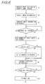
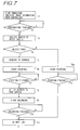
- Fig. 6 is a flowchart showing a processing of the controller 3.
- the controller 3 receives print data from the computer 4 and acquires IP address of the computer 4 (S1).
- image information of the print data is developed (S2) and the image information is transmitted to the stencil printer 1 as data which the stencil printer 1 can print (S3).
- the stencil printer 1 starts perforating image onto stencil paper based on the image information and when the perforating (stencil making) operation is finished (S4-Y), the stencil printer 1 is set with a number of print sheets from accompanying information of the print data (S5).
- a determination (S6) of whether the tape sorter 2 is used is executed by operation instruction and setting from the computer 4 or setting of the controller 3.
- IP address of the computer 4 is set to the stencil printer 4 (S7).
- IP address is not set.
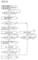
- Fig. 7 is a flowchart showing a processing of the stencil printer 1.
- the stencil printer 1 starts perforating by receiving image information developed from the controller 3 (T1).
- the stencil printer acquires a number of print sheets from the controller 3 and sets the number (T3). Further, data indicating whether the tape sorter 2 is used is received, when the tape sorter 2 is used (T4-Y), IP address of the computer 4 is acquired (T5).
- the tape sorter 2 reels out the tape 16 and starts recording of IP address (T9). Further, when the tape 16 has been finished feeding (T10-Y), the tape is cut and placed on the printed matter. Reception of successive print data (job) is awaited for (T11).
- the printed matters 12 are loaded by interposing the tape strips 16a recorded with IP addresses of the respective computers 4.
- Fig. 8 is a flowchart showing a processing of the controller 3.
- the controller 3 receives print data from the computer 4 and acquires IP address of the computer 4 (S1).
- the controller 3 allocates a predetermined numeral in correspondence with the IP address in an order (S12). For example, a numeral in an ascending order is allocated. A correspondence between once-allocated numeral and corresponding IP address is stored to an involatile storage element (for example, EEPROM) provided to the controller 3. Conversely, when acquired IP address has already been allocated (S11-N), stored corresponding numeral is read.
- image information of print data is developed (S2) and the image information is transmitted to the stencil printer 1 as data which the stencil printer 1 can print (S3).
- the stencil printer 1 starts perforating based on the image information and when perforating has been finished (S4-Y), a number of print sheets is set to the stencil printer 1 from accompanying information of the print data (S5).
- the allocated numeral is set to the stencil printer 4 (S13).
- Fig. 9 is a flowchart showing a processing of the stencil printer 1.
- the stencil printer 1 receives image information developed from the controller 3 and starts perforating image onto stencil paper (T1).
- T2-Y When perforating operation has been finished (T2-Y), a number of print sheet is acquired from the controller 3 and the number is set (T3). Further, data indicating whether the tape sorter 2 is used is received and when the tape sorter 2 is used (T4-Y), a numeral which the controller 3 allocates to the stencil printer 4 is acquired (T12).
- printing is started by using perforated stencil sheet (T6), and when printing has been finished (T7-Y), a numeral allocated is set to the tape sorter 2 (T13).
- the tape sorter 2 reels out the tape 16 and starts recording the numeral (T9). Further, when the tape 16 has been finished feeding (T10-Y), the tape is cut and placed on the printed matter. Reception of successive print data (job) is awaited for (T11).
- the computer 4 is allocated with the predetermined numeral and thereafter, in the case of the computer 4, the allocated numeral is not changed and is recorded on the tape strip 16a.
- T4-N when the tape sorter 2 is not used (T4-N), IP address is not set, printing is started by using perforated stencil sheet (T6a) and when printing has been finished (T7a-Y), the operation proceeds to T11.
- the processing at the controller 3 is similar to that in Fig. 6 and acquired IP address of the computer 4 is transmitted to the stencil printing apparatus 1.
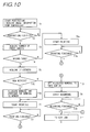
- Fig. 10 is a flowchart showing the processing of the stencil printer 1.
- the stencil printer 1 starts perforating image onto stencil sheet while receiving image information developed from the controller 3 (T1).
- T2-Y When perforating operation has been finished (T2-Y), a number of print sheets is acquired from the controller 3 and the number is set (T3). Further, data indicating whether the tape sorter 2 is used is received and when the tape sorter 2 is used (T4-Y), IP address transmitted from the controller 3 is acquired (T5).
- the stencil printer 1 allocates a predetermined numeral in correspondence with the IP address in an order (T16). For example, a numeral in an ascending order is allocated. A correspondence between once-allocated numeral and corresponding IP address is stored to an involatile storage element (for example, EEPROM) provided to the stencil printer 1. Conversely, when the acquired IP address has already been allocated (T15-N), stored corresponding numeral is read.
- a predetermined numeral in correspondence with the IP address in an order For example, a numeral in an ascending order is allocated.
- an involatile storage element for example, EEPROM
- printing is started by using perforated stencil sheet (T6) and when printing has been finished (T7-Y), numeral allocated is set to the tape sorter 2 (T13).
- the tape sorter 2 reels out the tape 16 and starts recording the numeral (T9). Further, when the tape 16 has been finished feeding (T10-Y), the tape is cut and placed on the printed matter. Reception of successive print data (job) is awaited for (T11).
- the computer 4 is allocated with the predetermined numeral, thereafter, in the case of the computer 4, the allocated numeral is not changed and is recorded on the tape strip 16a.
- the printed matters 12 from other computer 4 is discharged on the paper discharge base 10, the printed matters 12 are loaded while interposing the tape strip 16a recorded with the numeral allocated to the computer 4 operated by the user and accordingly, it can easily be determined that printed matters just below the tape strip 16a recorded with the numeral of the computer 4 used by the user belong to the user.
- the processing at the controller 3 is similar to that in Fig. 6 and acquired IP address of the computer 4 is transmitted to the stencil printing apparatus 1.
- Fig. 11 is a flowchart showing the processing of the stencil printer 1.
- Names of user of respective computer 4 are previously stored at ROM 32 or the like in the stencil printer 1 (T20).
- the respective computer 4 is respectively provided with IP address and name of user is stored in the form in correspondence with the IP address.
- the stencil printer 1 receives image information developed from the controller 3 and starts perforating image onto stencil sheet (T1).
- T2-Y When perforating has been finished (T2-Y), a number of print sheets is acquired from the controller 3 and the number is set (T3). Further, data indicating whether the tape sorter 2 is used is received and when the tape sorter 2 is used (T4-Y), IP address transmitted from the controller 3 to the stencil printer 4 is acquired (T5).
- the tape sorter 2 reels out the tape 16 and starts recording the set data (user name or IP address) (T9). Further, when the tape 16 has been finished feeding (T10-Y), reception of successive print data (job) is awaited for (T11).
- the tape sorter 2 is used as the simplified classifying apparatus.
- the present invention is not limited to the constitution of utilizing the tape sorter 2. That is, in the following constitution, an explanation will be given of a sorter 40 which does not use the tape sorter 2 for mounting (interposing) the tape strip 16a on the printed matters 12.
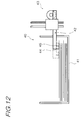
- Fig. 12 is a side view showing the sorter 40.
- the sorter 40 is constituted by an arm 42 elongated above a paper discharge base 41 and an arm drive unit 43 driving the arm 42 in the up and down direction and the left and right direction of the drawing.
- the arm 42 is provided with a friction member 44 of rubber or the like and a printing section 45 on a lower face of a front end thereof.
- the sorter 40 controls operation such that after finishing one time print job, another sheet of print paper is discharged from a printing section to the stencil printer for classification.
- the discharged print paper may be brought into a state in which print image is formed on its surface by a printing section or may be constituted to discharge in a state of white paper by a constitution of constructing other transfer path not by way of the printing section.
- the arm drive unit 43 moves the arm 42 such that the printing section 45 faces the uppermost face of the printed matters 12. Further, under the state, the above-described IP address, numeral, user name, sign or the like is recorded at an end portion of print paper at the uppermost face as user information by the printing section 45.
- the arm drive unit 43 is moved to the printing section side (position shifted from the loaded printed matters 12) in a state in which the friction member 44 of the arm 42 is brought into contact with the uppermost face of the print paper. Thereby, the print paper at the uppermost face is pulled back to the printing section side by a friction effect of rubber.
- the arm 42 is moved in the upward direction by a very small amount and thereafter returned to an escape position on the printing section side.
- At least a portion of print paper recorded with user information for classification is projected from an end face of other printed matter loaded on the paper discharge base and accordingly, printed matter on the paper discharge base can be classified and user information can be identified easily. Further, an identifier according to the constitution is print paper at the uppermost face.
- print paper at the uppermost face can be used as an identifier as it is even when extra discharged sheet is not used as print paper for classification.
- the present invention is not limited thereto but similar operation and effect can be achieved in the case of other apparatus connected to a plurality of computers via a network for forming image on print paper even when the apparatus is applied to a printer, a copier or the like.
- the present invention there is constructed the constitution in which even when a plurality of users utilizing computers on a network carry out printing of a large number of copy respectively by the same image forming apparatus, there is inserted an identifier described with user information inherent to a computer into printed matter of the image forming apparatus and accordingly, a user can simply find out printed matter of the user in all of printed matters loaded by the image forming apparatus. At the same time, printed matter of other person is not erroneously taken out, further, there can be resolved a problem in which printed matter which belongs to a person who is not known remains.
- the user information is recorded with characters, numerals, signs and the like which are easy to understand by a user such as address inherent to computer, numeral, user information or the like classified by computer, which can be identified easily.
- the identifier can be constituted by a tape using a tape sorter or print paper and is constituted to be inserted separately from print paper formed with image and accordingly, the identifier can simply be removed from a bundle of the printed matters after taking out only necessary printed matter from the image forming apparatus, further, the identifier does not effect influence on image of the printed matter.
Abstract
Description
- The present invention relates to an image forming apparatus of a stencil printer or the like having a tape sorter which is a simplified classifying apparatus, particularly to an image forming apparatus having a constitution in which computers of a plurality of users are connected to an image forming apparatus via a network and capable of easily identifying printed matters according to users when a plurality of users carry out printing of a large number of sheets in a large number of copies in the image forming apparatus.
- There is provided a tape sorter as a simplified classifying apparatus. The tape sorter is provided at a paper discharge unit of an image forming apparatus such as a printer or the like. The tape sorter is used when users carry out printing of a large number of sheets in a large number of copies and for example, in determining breaks of a number of copies of printed matters, strips of tape are inserted by a unit of copy.
- When an image forming apparatus having such a tape sorter is used by a single user, outputted printed matters are successively outputted and strips of tape are inserted by a unit of copy intended by the user.
- Now consider a case in which computers of a plurality of users are connected to one image forming apparatus via a network and print data from the plurality of users are outputted to the one image forming apparatus.
- In such a case, pluralities of printed matters of respective users are mixed at a paper discharge unit of the image forming apparatus and it cannot be determined at what location of the paper discharge unit one's own outputted printed matters are disposed. For example, even when the above-described tape sorter processes to insert strips of tape by a unit of respective copy, it cannot be determined which tapes correspond to the one's own outputted printed matters.
- Despite insertion of the strips of tape, extra time and labor is needed since all of the printed matters must be confirmed for the respective strips of tape in order to find out which printed matters divided by the tape portions are one's own printed matters.
- Further, in the case in which an outputted printed matter is a printed matter having a plurality of pages, further time and labor is needed in search therefor.
- The present invention has been carried out in order to resolve the above-described problem and it is an object of the present invention to provide an image forming apparatus in which in a constitution in which computers of a plurality of users are connected to the image forming apparatus via a network and the respective users can easily determine printed matters of the users.
- In order to achieve the above-described object, according to an aspect of the present invention, there is provided an image forming apparatus comprising a printing section inputted with a print job from a computer via a network for forming an image of the print job on print paper, a paper discharge unit loaded with the print paper formed with the image, a classifying unit for classifying the print paper loaded at the paper discharge unit by inserting an identifier, means for acquiring user information of the computer outputting the print job on the network, and a recording unit for recording the acquired user information to the identifier.
- Further, according to another aspect of the present invention, the user information may be inherent to the respective computer.
- Further, according to another aspect of the present invention, the user information recorded to the identifier may be an address inherent to the computer detected on the network.
- Further, according to another aspect of the present invention, the user information recorded to the identifier may be a name inherent to the computer detected on the network.
- Further, according to another aspect of the present invention, there may be constructed a constitution further comprising storing means for previously storing an address of the respective computer and predetermined numerals, characters or signs in correspondence with the address, wherein the means for acquiring the user information detects the address inherent to the computer outputting the print job and records the predetermined numerals, characters or signs in correspondence with the address as the user information.
- Further, according to another aspect of the present invention, there may be constructed a constitution wherein the means for acquiring the user information is a controller for controlling transmission and reception of data on the network and the print job outputted from the respective computer, and the controller detects an address of the computer outputting the print job and outputs the predetermined numerals, characters or signs stored in correspondence with the address to the classifying unit as the user information.
- Further, according to another aspect of the present invention, there may be constructed a constitution wherein the means for acquiring the user information is a controller for controlling transmission and reception of data on the network and the print job outputted from the respective computer, the controller detects the address of the computer outputting the print job and outputs the address to the classifying unit, and the classifying unit records predetermined numerals, characters or signs stored in correspondence with the inputted address to the identifier as the user information.
- Further, according to another aspect of the present invention, there may be constructed a constitution wherein the classifying unit comprises a tape sorter comprising a feeding unit for inserting a tape strip having a predetermined length on a printed matter loaded at the paper discharge unit such that a portion of the tape strip is displayed as the identifier when the print job from the respective computer has been finished, and a recording unit for recording the user information on the displayed portion of the tape strip.
- Further, according to another aspect of the present invention, there may be constructed a constitution wherein the identifier is constituted by the print paper, further comprising means for recording the user information on the print paper as the identifier and shifting a position of loading the print paper as the identifier relative to other of the print paper such that the recorded portion is displayed.
- Further, according to another aspect of the present invention, there may be constructed a constitution wherein the recording unit comprises an ink jet head, a thermal head or the like for recording the user information.
- According to the above-described constitutions, transmission and reception of data on the network and the print job are controlled by the controller and the address or characters or signs inherent to the computer is transmitted to the image forming apparatus as the user information. The image forming apparatus receives the user information and transmits the user information to the tape sorter which is the classifying apparatus every time of finishing the print job.
- The tape sorter records the address or the characters or signs in place thereof inherent to the computer as the user information on the tape, cuts the tape and mounts the cut tape at the uppermost portion of the printed matter. Thereby, when the plurality of users utilizing the network computers printing carry out a processing with regard to the image forming apparatus, the user information of address or the like of personal computers of their own is recorded on the tape in characters or signs and accordingly, users can easily find out object printed matters among the mixed printed matters. Thereby, the printed matters belonging to the users can immediately be determined from among a large number of copies of the printed matters outputted by the plurality of computer users.
- Preferred embodiments of the invention will now be described by way of example with reference to the accompanying drawings, in which:
- Fig. 1 is a total constitution view showing an embodiment of an image forming apparatus according to the present invention;
- Fig. 2 is a perspective view showing a state of classifying printed matters;
- Fig. 3 is a side view showing a constitution of a classifying apparatus;
- Fig. 4 is a plane view showing the constitution of the classifying apparatus;
- Fig. 5 is a block diagram showing a control constitution of the classifying apparatus;
- Fig. 6 is a flowchart showing a processing of a controller according to a first embodiment of the present invention;
- Fig. 7 is a flowchart showing a processing of a stencil printer according to the first embodiment of the present invention;
- Fig. 8 is a flowchart showing a processing of a controller according to a second embodiment of the present invention;
- Fig. 9 is a flowchart showing a processing of a stencil printer according to the second embodiment of the present invention;
- Fig. 10 is a flowchart showing a processing of a stencil printer according to a third embodiment of the present invention;
- Fig. 11 is a flowchart showing a processing of a stencil printer according to a fourth embodiment of the present invention; and
- Fig. 12 is a side view showing other constitution example of a classifying apparatus according to a fifth embodiment of the present invention.
-
- An explanation will be given of embodiments of the present invention. Fig. 1 is a total constitution view showing a state in which an image forming apparatus is connected to a network. An explanation will be given of an example of a stencil printer having a tape sorter as a simplified classifying apparatus as follows.
- A
tape sorter 2 is provided at a paper discharge unit of astencil printer 1 shown in Fig. 1. Thestencil printer 1 includes thetape sorter 2 and acontroller 3. - The
stencil printer 1 comprises a perforating section for perforating a stencil sheet in an image-pattern, a printing section having a perforated stencil sheet wrapped thereon for rotationally printing a print paper, a paper feed mechanism and a paper transfer mechanism of print paper, and a paper discharge unit having discharged printed paper as printed matter loaded thereon. The paper discharge unit is provided with thetape sorter 2 for transmitting tape as an identifier in classifying printed matter loaded on a paper discharge base. - The
controller 3 is connected to computers (personal computers) 4 via a network of LAN or the like. A plurality of thecomputers 4 are provided on the network and are constructed by a constitution in which thestencil printer 1 can be used by a plurality of users. - The
computer 4 outputs print data of information of image intended to print as well as accompanying information of a number of sheets of printing, a number of copies and the like and thecontroller 3 acquires user information of thecomputer 4 and outputs the information to thestencil printer 1 along with the print data. - Next, an explanation will be given of the
tape sorter 2. The basic structure of the tape sorter is disclosed in Japanese Utility Model Laid-Open No. 45654/1989. - Fig. 2 is a view showing a state of classifying printed matters by using the
tape sorter 2. According to the drawing, among printedmatters 12 discharged from thestencil printer 1 and loaded on thepaper discharge base 10,tape strips 16a can be inserted by a unit of print job (a desired number of sheets and a desired number of copies). - The user information is recorded on an end portion of the
tape strip 16a and the user information is displayed out at a side position from an end face of the loaded printed matters. Thereby, even in a state loaded with the printedmatters 12, the user information can be visually recognized. - Fig. 3 is a front view showing a constitution of the tape sorter and Fig. 4 is a plane view thereof.
- A pair of
rollers 17 for transferring atape 16 in a roll-like shape is constituted by acapstan roller 17a formed with a groove in a V-like shape at its peripheral face and apinch roller 17b a peripheral edge portion of which is sharpened and opposed to the groove. A rotating shaft of thecapstan roller 17a is connected with a motor M via agear 18 and thetape 16 is sandwiched by thecapstan roller 17a and thepinch roller 17b and thetape 16 is fed by a predetermined amount while being reeled out from the roll and bent in a V-like shape in its section. - A
cutter device 19 for cutting thetape 16 fed by the predetermined amount is provided frontward from the pair ofrollers 17 for feeding the tape. Thecutter device 19 is constituted by amovable blade 19a and afixed blade 19b provided at a position supporting the transferredtape 16 and opposed to themovable blade 19a. After finishing transfer of thetape 16 by the predetermined amount, thecutter device 19 cuts thetape 16 by driving themovable blade 19a connected to a cutter solenoid SLA. - Further, a
tape supporting plate 20 for supporting thetape 16 reeled out from the tape roll is provided between thetape 16 wound in the roll shape and the pair ofrollers 17 and there is provided arecording section 21 for printing the user information on thetape strip 16a inserted among printed matters for classifying above thetape supporting plate 20. - The
recording section 21 is provided with any of a stamping mechanism, a thermal head, an ink jet head and the like and records the inputted user information on thetape strip 16a. - Further, when a classifying signal is outputted from the stencil printer, at first, the motor M is driven and the predetermined amount of the
tape 16 is transferred, then, therecording section 21 is driven and the predetermined user information is recorded on thetape 16. Thereby, as shown by Fig. 2, the user information is recorded on a rear end of thetape strip 16a to project by a predetermined amount from a position of an end portion of the printed matter. - Fig. 5 is a block diagram for control means according to the
tape sorter 2 provided in the image forming apparatus. Here, image information in print data inputted from thecontroller 3 is outputted to the printing section, not illustrated. - The control means 30 is provided with a
processing unit 31 constituted by a microprocessor or the like. Programs for controlling respective mechanism of the tape sorter are stored inROM 32. - Further, accompanying information and user information in the print data are inputted to the
processing unit 31 and stored inRAM 33. Apaper discharge sensor 34 detects print paper discharged from the printing section. - The
processing unit 31 controls to drive the motor M, the cutter solenoid SLA and therecording section 21 provided to the tape sorter. - The motor M is connected to the
rollers 17 for feeding thetape 16. The cutter solenoid SLA is connected to thecutter device 19 for cutting tape fed by a predetermined length. - An explanation will be given of control content of the control means 30. The control means 30 is inputted with the accompanying information and the user information from the
controller 3 for respective print job. Further, when for example, 20 sheets of printing is carried out for one time print job based on the accompanying information, "20" is set to store to RAM 33 as a set print number of sheets. - Further, when printing is executed by the
stencil printer 1, discharged print paper is detected by thedischarge paper sensor 34. Theprocessing unit 31 counts a number of sheets of discharge paper, compares the number with the set print number of sheets stored to RAM 33 and executes a processing of feeding thetape 16 when the counted number of sheets coincides with the set print number of sheets. - Specifically, the motor M is driven, the
pinch roller 17b and thecapstan roller 17a are driven to rotate and a predetermined amount of thetape 16 is fed toward an upper face of the printed matters 12. At this occasion, theprocessing unit 31 transmits the user information to therecording section 21 and the user information is recorded on the fedtape 16. - Thereafter, the
processing unit 31 outputs a signal for cutting thetape 16 at a predetermined timing to the cutter solenoid SLA. Thereby, the cutter solenoid SLA is driven, thetape 16 fed to above the printed matters 12 is cut and is mounted on an uppermost face of the print paper as thetape strip 16a. - Further, the
processing unit 31 judges whether printing is repeated by the set print number stored inRAM 33. If not, printing of the next set of print papers is repeated similarly to the operation described above. When judged otherwise, printing is finished. - Next, an explanation will be given of the tape sorter having the above-described constitution in the case in which the
stencil printer 1 is connected with a network. - A user outputs print data to the
stencil printer 1 via the network as one time print job. - The
controller 3 receives the print data from thecomputer 4 and acquires user information of thecomputer 4. At this occasion, thecontroller 3 acquires an IP address of thecomputer 4 as user information for respective print job. The IP address is an address for identifying a transmission source in communication under a procedure of TCP/IP. - The
controller 3 converts image information in the print data into data which thestencil printer 1 can print and thereafter transmits data to thestencil printer 1 to thereby make thestencil printer 1 execute perforating. - After perforating operation, the
stencil printer 1 is provided with a number of sets of print sheets and a number of print sheets in each set on the basis of accompanying information of the print data before executing printing operation. Further, thestencil printer 1 is made to execute printing of predetermined numbers of print sheets for respective number of copies. Further, the IP address (strictly speaking, character row of IP address) which is intended to print is transmitted to theprocessing unit 31 of thetape sorter 2. - The
stencil printer 1 operates thetape sorter 2 after finishing to print designated print number of sheets. Thetape sorter 2 records the inputted IP address onto thetape 16 by therecording section 21, thereafter feeds a predetermined amount of thetape 16 and cuts thetape 16. - In this way, the
controller 3 similarly operates thetape sorter 2 every time of reaching the designated print number of sheets (every predetermined number of copy) for respective print job. Thereby, the printed matters 12 loaded on thedischarge paper base 10 is inserted with the tape strips 16a described with IP addresses of thecomputers 4 by a unit of a number of copy. - Further, presence or absence of utilization of the
tape sorter 2 as well as presence or absence of printing of a user information (IP address) by utilizing thetape sorter 2 can be respectively operated or set at thecomputer 4. - Next, an explanation will be given of printing operation of one time print job (one number of copy) in reference to Fig. 6 and Fig. 7.
- Fig. 6 is a flowchart showing a processing of the
controller 3. - The
controller 3 receives print data from thecomputer 4 and acquires IP address of the computer 4 (S1). - Next, image information of the print data is developed (S2) and the image information is transmitted to the
stencil printer 1 as data which thestencil printer 1 can print (S3). - The
stencil printer 1 starts perforating image onto stencil paper based on the image information and when the perforating (stencil making) operation is finished (S4-Y), thestencil printer 1 is set with a number of print sheets from accompanying information of the print data (S5). - Further, a determination (S6) of whether the
tape sorter 2 is used is executed by operation instruction and setting from thecomputer 4 or setting of thecontroller 3. - When the
tape sorter 2 is used (S6-Y), IP address of thecomputer 4 is set to the stencil printer 4 (S7). - Meanwhile, when the
tape sorter 2 is not used (S6-N), IP address is not set. - Next, execution of printing is instructed to the stencil printer 1 (S8).
- When printing operation of the
stencil printer 1 has been finished (S9-Y), reception of successive print data (job) is awaited for (S10). - Fig. 7 is a flowchart showing a processing of the
stencil printer 1. - The
stencil printer 1 starts perforating by receiving image information developed from the controller 3 (T1). - When perforating operation has been finished (T2-Y), the stencil printer acquires a number of print sheets from the
controller 3 and sets the number (T3). Further, data indicating whether thetape sorter 2 is used is received, when thetape sorter 2 is used (T4-Y), IP address of thecomputer 4 is acquired (T5). - Further, printing is started by using perforated stencil sheet (T6). When printing is finished (T7-Y), IP address is set to the tape sorter 2 (T8).
- The
tape sorter 2 reels out thetape 16 and starts recording of IP address (T9). Further, when thetape 16 has been finished feeding (T10-Y), the tape is cut and placed on the printed matter. Reception of successive print data (job) is awaited for (T11). - Under the state, on the
paper discharge base 10, one set of the printed matters 12 is loaded, and thetape strip 16a with IP address recorded thereon is placed on the uppermost face of the set. - Therefore, even when printing is carried out by print data of
other computers 4 at next job, the printed matters 12 are loaded by interposing the tape strips 16a recorded with IP addresses of therespective computers 4. Thereby, when a user of thecomputer 4 comes to thestencil printer 1 and takes out the printed matters 12 printed by the user, it can easily be determined that printed matters just below thetape strip 16a printed with the IP address of thecomputer 4 which the user has used are that of the user. - Further, when the
tape sorter 2 is not used (T4-N), without setting IP address, printing is started by using perforated stencil sheet (T6a). When printing is finished (T7a-Y) the operation proceeds to T11. Further, contents of printing processings are the same in T6 and T6a, and T7 and T7a. - Next, an explanation will be given of a second embodiment of the invention.
- According to the embodiment, there is added a processing in the case in which acquired IP address is new.
- An explanation will be given of printing operation of one time print job in reference to Fig. 8 and Fig. 9 as follows.
- Fig. 8 is a flowchart showing a processing of the
controller 3. - In the drawing, portions having processing contents the same as those in Fig. 6 are attached with the same notations. The
controller 3 receives print data from thecomputer 4 and acquires IP address of the computer 4 (S1). - At this occasion, when acquired IP address is new (S11-Y), the
controller 3 allocates a predetermined numeral in correspondence with the IP address in an order (S12). For example, a numeral in an ascending order is allocated. A correspondence between once-allocated numeral and corresponding IP address is stored to an involatile storage element (for example, EEPROM) provided to thecontroller 3. Conversely, when acquired IP address has already been allocated (S11-N), stored corresponding numeral is read. - Next, image information of print data is developed (S2) and the image information is transmitted to the
stencil printer 1 as data which thestencil printer 1 can print (S3). - The
stencil printer 1 starts perforating based on the image information and when perforating has been finished (S4-Y), a number of print sheets is set to thestencil printer 1 from accompanying information of the print data (S5). - Further, it is determined whether the
tape sorter 2 is used by operation instruction and setting from thecomputer 4 or setting of the controller 3 (S6). - When the
tape sorter 2 is used (S6-Y), the allocated numeral is set to the stencil printer 4 (S13). - In the meantime, when the
tape sorter 2 is not used (S6-N), the numeral is not set. - Next, execution of printing is instructed to the stencil printer 1 (S8).
- When printing of the
stencil printer 1 has been finished (S9-Y), reception of successive print data (job) is awaited for (S10). - Fig. 9 is a flowchart showing a processing of the
stencil printer 1. - The
stencil printer 1 receives image information developed from thecontroller 3 and starts perforating image onto stencil paper (T1). - When perforating operation has been finished (T2-Y), a number of print sheet is acquired from the
controller 3 and the number is set (T3). Further, data indicating whether thetape sorter 2 is used is received and when thetape sorter 2 is used (T4-Y), a numeral which thecontroller 3 allocates to thestencil printer 4 is acquired (T12). - In the meantime, when the
tape sorter 2 is not used (T4-N), a numeral is not set and the operation proceeds to T6a. - Further, printing is started by using perforated stencil sheet (T6), and when printing has been finished (T7-Y), a numeral allocated is set to the tape sorter 2 (T13). The
tape sorter 2 reels out thetape 16 and starts recording the numeral (T9). Further, when thetape 16 has been finished feeding (T10-Y), the tape is cut and placed on the printed matter. Reception of successive print data (job) is awaited for (T11). - Under the state, on the
paper discharge base 10, one set of the printed matters 12 is loaded, and thetape strip 16a with the numeral recorded thereon and allocated by thecontroller 3 is placed on the uppermost face of the set. - Thereby, in executing printing by the
stencil printer 1, thecomputer 4 is allocated with the predetermined numeral and thereafter, in the case of thecomputer 4, the allocated numeral is not changed and is recorded on thetape strip 16a. - Therefore, even when the printed matters 12 from
other computers 4 are successively discharged on thepaper discharge base 10, the printed matters 12 are loaded while interposing the tape strips 16a with the numerals recorded thereon and allocated to thecomputers 4 operated by the users. Thereby, when the user of thecomputer 4 comes to thestencil printer 1 and takes out the printed matters 12 printed by the user, it can easily be determined that printed matters just below thetape strip 16a recorded with numeral of thecomputer 4 used by the user belong to the user. - Further, when the
tape sorter 2 is not used (T4-N), IP address is not set, printing is started by using perforated stencil sheet (T6a) and when printing has been finished (T7a-Y), the operation proceeds to T11. - Further, there may be constructed a constitution in which signs are recorded in place of numerals. In this case, there is constructed a constitution in which predetermined signs are allocated to the
respective computers 4. - Next, an explanation will be given of a third embodiment of the invention as follows.
- According to the embodiment, there is constructed a constitution in which when acquired IP address is new, a predetermined processing is carried out at the
stencil printing apparatus 1. Therefore, the processing at thecontroller 3 is similar to that in Fig. 6 and acquired IP address of thecomputer 4 is transmitted to thestencil printing apparatus 1. - Fig. 10 is a flowchart showing the processing of the
stencil printer 1. - The
stencil printer 1 starts perforating image onto stencil sheet while receiving image information developed from the controller 3 (T1). - When perforating operation has been finished (T2-Y), a number of print sheets is acquired from the
controller 3 and the number is set (T3). Further, data indicating whether thetape sorter 2 is used is received and when thetape sorter 2 is used (T4-Y), IP address transmitted from thecontroller 3 is acquired (T5). - At this occasion, when IP address acquired is new (T15-Y), the
stencil printer 1 allocates a predetermined numeral in correspondence with the IP address in an order (T16). For example, a numeral in an ascending order is allocated. A correspondence between once-allocated numeral and corresponding IP address is stored to an involatile storage element (for example, EEPROM) provided to thestencil printer 1. Conversely, when the acquired IP address has already been allocated (T15-N), stored corresponding numeral is read. - Further, printing is started by using perforated stencil sheet (T6) and when printing has been finished (T7-Y), numeral allocated is set to the tape sorter 2 (T13). The
tape sorter 2 reels out thetape 16 and starts recording the numeral (T9). Further, when thetape 16 has been finished feeding (T10-Y), the tape is cut and placed on the printed matter. Reception of successive print data (job) is awaited for (T11). - Under the state, on the
paper discharge base 10, one set of the printed matters 12 is loaded, and thetape strip 16a with the numeral recorded thereon and allocated by thestencil printer 1 is placed on the uppermost face of the set. - Thereby, when printing is executed by the
stencil printer 1, thecomputer 4 is allocated with the predetermined numeral, thereafter, in the case of thecomputer 4, the allocated numeral is not changed and is recorded on thetape strip 16a. - Also according to the embodiment, the printed matters 12 from
other computer 4 is discharged on thepaper discharge base 10, the printed matters 12 are loaded while interposing thetape strip 16a recorded with the numeral allocated to thecomputer 4 operated by the user and accordingly, it can easily be determined that printed matters just below thetape strip 16a recorded with the numeral of thecomputer 4 used by the user belong to the user. - Further, when the
tape sorter 2 is not used (T4-N), numeral is not allocated, printing is started by using perforated stencil sheet (T6a) and when printing is finished (T7a-Y), the operation proceeds to T11. - Next, an explanation will be given of a fourth embodiment of the invention as follows.
- According to the embodiment, there is constructed a constitution in which name of user in correspondence with IP address is previously stored to the
stencil printer 1 and a constitution in which a predetermined processing is carried out at thestencil printing apparatus 1. Therefore, the processing at thecontroller 3 is similar to that in Fig. 6 and acquired IP address of thecomputer 4 is transmitted to thestencil printing apparatus 1. - Fig. 11 is a flowchart showing the processing of the
stencil printer 1. - Names of user of
respective computer 4 are previously stored atROM 32 or the like in the stencil printer 1 (T20). In this case, therespective computer 4 is respectively provided with IP address and name of user is stored in the form in correspondence with the IP address. - Further, the
stencil printer 1 receives image information developed from thecontroller 3 and starts perforating image onto stencil sheet (T1). - When perforating has been finished (T2-Y), a number of print sheets is acquired from the
controller 3 and the number is set (T3). Further, data indicating whether thetape sorter 2 is used is received and when thetape sorter 2 is used (T4-Y), IP address transmitted from thecontroller 3 to thestencil printer 4 is acquired (T5). - Further, printing is started by using perforated stencil sheet (T6) and when printing has been finished (T7-Y), whether acquired IP address is registered is checked (T21).
- If the acquired IP address is already registered (T21-Y), name of user (character) in correspondence with the IP address is set to the tape sorter 2 (T22). In the meantime, if not (T21-N), the IP address is set to the tape sorter 2 (T23).
- Further, the
tape sorter 2 reels out thetape 16 and starts recording the set data (user name or IP address) (T9). Further, when thetape 16 has been finished feeding (T10-Y), reception of successive print data (job) is awaited for (T11). - Under the state, on the
paper discharge base 10, one set of the printed matters 12 is loaded, and thetape strip 16a recorded with the user name of thecomputer 4 is placed on the uppermost face of the set. Further, in the case of thecomputer 4 not registered to thestencil printer 1, thetape strip 16a recorded with IP address of thecomputer 4 is mounted. - Therefore, even when the printed matters 12 from
other computer 4 is discharged on thepaper discharge base 10, the printed matters 12 is loaded while interposing thetape strip 16a having the user name recorded thereon. - Thereby, when the user of the
computer 4 comes to thestencil printer 1 and takes out the printed matters 12 printed by the user, it can easily be determined that printed matters just below thetape strip 16a recorded with the numeral of thecomputer 4 used by the user belong to the user. - Further, when the
tape sorter 2 is not used (T4-N), printing of user name is not carried out, printing is started by using perforated stencil sheet (T6a) and when printing has been finished (T7a-Y), the operation proceeds to T11. - Next, an explanation will be given of a fifth embodiment of the invention.
- According to any of the above-described respective embodiments, an explanation has been given of the constitution in which the
tape sorter 2 is used as the simplified classifying apparatus. The present invention is not limited to the constitution of utilizing thetape sorter 2. That is, in the following constitution, an explanation will be given of asorter 40 which does not use thetape sorter 2 for mounting (interposing) thetape strip 16a on the printed matters 12. - Fig. 12 is a side view showing the
sorter 40. - The
sorter 40 is constituted by anarm 42 elongated above apaper discharge base 41 and anarm drive unit 43 driving thearm 42 in the up and down direction and the left and right direction of the drawing. Thearm 42 is provided with afriction member 44 of rubber or the like and aprinting section 45 on a lower face of a front end thereof. - The
sorter 40 controls operation such that after finishing one time print job, another sheet of print paper is discharged from a printing section to the stencil printer for classification. - The discharged print paper may be brought into a state in which print image is formed on its surface by a printing section or may be constituted to discharge in a state of white paper by a constitution of constructing other transfer path not by way of the printing section.
- Next, the
arm drive unit 43 moves thearm 42 such that theprinting section 45 faces the uppermost face of the printed matters 12. Further, under the state, the above-described IP address, numeral, user name, sign or the like is recorded at an end portion of print paper at the uppermost face as user information by theprinting section 45. - After finishing to print, the
arm drive unit 43 is moved to the printing section side (position shifted from the loaded printed matters 12) in a state in which thefriction member 44 of thearm 42 is brought into contact with the uppermost face of the print paper. Thereby, the print paper at the uppermost face is pulled back to the printing section side by a friction effect of rubber. - Thereafter, when several new sheets of the printed matters 12 are loaded on the paper discharge base, the
arm 42 is moved in the upward direction by a very small amount and thereafter returned to an escape position on the printing section side. - According to the embodiment, at least a portion of print paper recorded with user information for classification is projected from an end face of other printed matter loaded on the paper discharge base and accordingly, printed matter on the paper discharge base can be classified and user information can be identified easily. Further, an identifier according to the constitution is print paper at the uppermost face.
- Further, print paper at the uppermost face can be used as an identifier as it is even when extra discharged sheet is not used as print paper for classification.
- By using such a
sorter 40, there can be constructed a constitution in which the user information explained in the above-described respective embodiments is similarly recorded and a unit of copy can be identified without using thespecial tape 16 and thesorter 2. - Although according to the above-described embodiments, an explanation has been given of an example of the stencil printer as an image forming apparatus, the present invention is not limited thereto but similar operation and effect can be achieved in the case of other apparatus connected to a plurality of computers via a network for forming image on print paper even when the apparatus is applied to a printer, a copier or the like.
- As has been explained above, according to the present invention, there is constructed the constitution in which even when a plurality of users utilizing computers on a network carry out printing of a large number of copy respectively by the same image forming apparatus, there is inserted an identifier described with user information inherent to a computer into printed matter of the image forming apparatus and accordingly, a user can simply find out printed matter of the user in all of printed matters loaded by the image forming apparatus. At the same time, printed matter of other person is not erroneously taken out, further, there can be resolved a problem in which printed matter which belongs to a person who is not known remains. The user information is recorded with characters, numerals, signs and the like which are easy to understand by a user such as address inherent to computer, numeral, user information or the like classified by computer, which can be identified easily.
- The identifier can be constituted by a tape using a tape sorter or print paper and is constituted to be inserted separately from print paper formed with image and accordingly, the identifier can simply be removed from a bundle of the printed matters after taking out only necessary printed matter from the image forming apparatus, further, the identifier does not effect influence on image of the printed matter.
Claims (10)
- An image forming apparatus comprising:a printing section inputted with a print job from a computer via a network for forming an image of the print job on print paper;a paper discharge unit loaded with the print paper formed with the image;a classifying unit for classifying the print paper loaded at the paper discharge unit by inserting an identifier;means for acquiring user information of the computer outputting the print job on the network; anda recording unit for recording the acquired user information to the identifier.
- The image forming apparatus according to Claim 1:
wherein the user information is inherent to the respective computer. - The image forming apparatus according to Claim 2:
wherein the user information recorded to the identifier is an address inherent to the computer detected on the network. - The image forming apparatus according to Claim 2:
wherein the user information recorded to the identifier is a name inherent to the computer detected on the network. - The image forming apparatus according to Claim 1, further comprising:
storing means for previously storing an address of the respective computer and predetermined numerals, characters or signs in correspondence with the address;
wherein the means for acquiring the user information detects the address inherent to the computer outputting the print job and records the predetermined numerals, characters or signs in correspondence with the address as the user information. - The image forming apparatus according to Claim 1:
wherein the means for acquiring the user information is a controller for controlling transmission and reception of data on the network and the print job outputted from the respective computer; and
wherein the controller detects an address of the computer outputting the print job and outputs predetermined numerals, characters or signs stored in correspondence with the address to the classifying unit as the user information. - The image forming apparatus according to Claim 1:
wherein the means for acquiring the user information is a controller for controlling transmission and reception of data on the network and the print job outputted from the respective computer;
wherein the controller detects the address of the computer outputting the print job and outputs the address to the classifying unit; and
wherein the classifying unit records predetermined numerals, characters or signs stored in correspondence with the inputted address to the identifier as the user information. - The image forming apparatus according to any one of Claims 1 through 7:
wherein the classifying unit comprises a tape sorter comprising:a feeding unit for inserting a tape strip having a predetermined length on a printed matter loaded at the paper discharge unit such that a portion of the tape strip is displayed as the identifier when the print job from the respective computer has been finished; anda recording unit for recording the user information on the displayed portion of the tape strip. - The image forming apparatus according to any one of Claims 1 through 7:
wherein the identifier is constituted by the print paper, further comprising:
means for recording the user information on the print paper as the identifier and shifting a position of loading the print paper as the identifier relative to other of the print paper such that the recorded portion is displayed. - The image forming apparatus according to Claim 8 or 9:
wherein the recording unit comprises an ink jet head, a thermal head or the like for recording the user information.
Applications Claiming Priority (2)
| Application Number | Priority Date | Filing Date | Title |
|---|---|---|---|
| JP16987399 | 1999-06-16 | ||
| JP16987399 | 1999-06-16 |
Publications (2)
| Publication Number | Publication Date |
|---|---|
| EP1061030A2 true EP1061030A2 (en) | 2000-12-20 |
| EP1061030A3 EP1061030A3 (en) | 2004-01-07 |
Family
ID=15894548
Family Applications (1)
| Application Number | Title | Priority Date | Filing Date |
|---|---|---|---|
| EP00305107A Withdrawn EP1061030A3 (en) | 1999-06-16 | 2000-06-16 | Image forming apparatus with a device for inserting marker slips in the delivery pile |
Country Status (1)
| Country | Link |
|---|---|
| EP (1) | EP1061030A3 (en) |
Cited By (3)
| Publication number | Priority date | Publication date | Assignee | Title |
|---|---|---|---|---|
| CN105523420A (en) * | 2015-12-25 | 2016-04-27 | 广东华凯科技股份有限公司 | Stacking label inserting device |
| CN111086910A (en) * | 2020-01-02 | 2020-05-01 | 汕头市顺鑫隆印刷机械有限公司 | Paper products automatic collection vanning device |
| CN112193905A (en) * | 2020-09-28 | 2021-01-08 | 深圳市立信印刷科技有限公司 | Sliding type paper pile counting auxiliary device for printing machine and using method thereof |
Citations (1)
| Publication number | Priority date | Publication date | Assignee | Title |
|---|---|---|---|---|
| JPS6445654A (en) | 1988-04-08 | 1989-02-20 | Oki Electric Ind Co Ltd | Printing head for dot printer |
Family Cites Families (5)
| Publication number | Priority date | Publication date | Assignee | Title |
|---|---|---|---|---|
| US5316279A (en) * | 1993-01-04 | 1994-05-31 | Xerox Corporation | Copier/printer job stacking with discrete cover sheets with extending printed banners |
| JPH09109513A (en) * | 1995-10-13 | 1997-04-28 | Hitachi Koki Co Ltd | Image recorder |
| US5897250A (en) * | 1996-04-26 | 1999-04-27 | Canon Kabushiki Kaisha | Sheet processing apparatus |
| US5704602A (en) * | 1996-10-18 | 1998-01-06 | Xerox Corporation | System for automatic print jobs separations in folders |
| NO312569B1 (en) * | 1997-11-28 | 2002-05-27 | Truong Viet Lam | Device for improving the utilization of a network by distributing information with banners |
-
2000
- 2000-06-16 EP EP00305107A patent/EP1061030A3/en not_active Withdrawn
Patent Citations (1)
| Publication number | Priority date | Publication date | Assignee | Title |
|---|---|---|---|---|
| JPS6445654A (en) | 1988-04-08 | 1989-02-20 | Oki Electric Ind Co Ltd | Printing head for dot printer |
Cited By (4)
| Publication number | Priority date | Publication date | Assignee | Title |
|---|---|---|---|---|
| CN105523420A (en) * | 2015-12-25 | 2016-04-27 | 广东华凯科技股份有限公司 | Stacking label inserting device |
| CN111086910A (en) * | 2020-01-02 | 2020-05-01 | 汕头市顺鑫隆印刷机械有限公司 | Paper products automatic collection vanning device |
| CN111086910B (en) * | 2020-01-02 | 2021-01-15 | 汕头市顺鑫隆印刷机械有限公司 | Paper products automatic collection vanning device |
| CN112193905A (en) * | 2020-09-28 | 2021-01-08 | 深圳市立信印刷科技有限公司 | Sliding type paper pile counting auxiliary device for printing machine and using method thereof |
Also Published As
| Publication number | Publication date |
|---|---|
| EP1061030A3 (en) | 2004-01-07 |
Similar Documents
| Publication | Publication Date | Title |
|---|---|---|
| US5897250A (en) | Sheet processing apparatus | |
| US4501224A (en) | Continuous tag printing apparatus | |
| US8803933B2 (en) | Printing apparatus and printing method | |
| EP1061030A2 (en) | Image forming apparatus with a device for inserting marker slips in the delivery pile | |
| EP0517480A1 (en) | Stencil master plate making printing device | |
| JP4876791B2 (en) | Image forming apparatus and program | |
| CN115967773A (en) | Printing method, storage medium and image forming apparatus | |
| JP3533044B2 (en) | Copying system equipment | |
| JP3298984B2 (en) | Tape launcher for printing press | |
| US6474885B2 (en) | Roller system to help remove chad and trimmed media in a thermal printer | |
| JP2000155506A (en) | Image forming device | |
| JPH11292381A (en) | Image forming device | |
| JP2001058753A (en) | Image forming device | |
| JPH05309890A (en) | Printing device | |
| JP3013554B2 (en) | Printing device | |
| JP3066407B2 (en) | Stencil printing machine | |
| JP2904039B2 (en) | Paper feeder | |
| JP3056540B2 (en) | Stencil printing machine | |
| US20040159998A1 (en) | Apparatus and method for improved print output | |
| JPH05136935A (en) | Facsimile equipment | |
| JPS592195A (en) | Ticketing equipment | |
| JPH02305266A (en) | Facsimile equipment | |
| JPH09290397A (en) | Label paper printing cut device | |
| JPS63208350A (en) | Facsimile equipment | |
| JPS62126766A (en) | Reception mechanism |
Legal Events
| Date | Code | Title | Description |
|---|---|---|---|
| PUAI | Public reference made under article 153(3) epc to a published international application that has entered the european phase |
Free format text: ORIGINAL CODE: 0009012 |
|
| 17P | Request for examination filed |
Effective date: 20000630 |
|
| AK | Designated contracting states |
Kind code of ref document: A2 Designated state(s): AT BE CH CY DE DK ES FI FR GB GR IE IT LI LU MC NL PT SE |
|
| AX | Request for extension of the european patent |
Free format text: AL;LT;LV;MK;RO;SI |
|
| PUAL | Search report despatched |
Free format text: ORIGINAL CODE: 0009013 |
|
| AK | Designated contracting states |
Kind code of ref document: A3 Designated state(s): AT BE CH CY DE DK ES FI FR GB GR IE IT LI LU MC NL PT SE |
|
| AX | Request for extension of the european patent |
Extension state: AL LT LV MK RO SI |
|
| RIC1 | Information provided on ipc code assigned before grant |
Ipc: 7G 06K 15/00 B Ipc: 7B 65H 33/04 A |
|
| AKX | Designation fees paid | ||
| REG | Reference to a national code |
Ref country code: DE Ref legal event code: 8566 |
|
| STAA | Information on the status of an ep patent application or granted ep patent |
Free format text: STATUS: THE APPLICATION IS DEEMED TO BE WITHDRAWN |
|
| 18D | Application deemed to be withdrawn |
Effective date: 20040708 |