EP1060865A2 - Process and device for opening and closing the moulds of a plastic moulding machine - Google Patents
Process and device for opening and closing the moulds of a plastic moulding machine Download PDFInfo
- Publication number
- EP1060865A2 EP1060865A2 EP00106773A EP00106773A EP1060865A2 EP 1060865 A2 EP1060865 A2 EP 1060865A2 EP 00106773 A EP00106773 A EP 00106773A EP 00106773 A EP00106773 A EP 00106773A EP 1060865 A2 EP1060865 A2 EP 1060865A2
- Authority
- EP
- European Patent Office
- Prior art keywords
- blow
- carriage
- platen
- yokes
- tool
- Prior art date
- Legal status (The legal status is an assumption and is not a legal conclusion. Google has not performed a legal analysis and makes no representation as to the accuracy of the status listed.)
- Withdrawn
Links
Images
Classifications
-
- B—PERFORMING OPERATIONS; TRANSPORTING
- B29—WORKING OF PLASTICS; WORKING OF SUBSTANCES IN A PLASTIC STATE IN GENERAL
- B29C—SHAPING OR JOINING OF PLASTICS; SHAPING OF MATERIAL IN A PLASTIC STATE, NOT OTHERWISE PROVIDED FOR; AFTER-TREATMENT OF THE SHAPED PRODUCTS, e.g. REPAIRING
- B29C49/00—Blow-moulding, i.e. blowing a preform or parison to a desired shape within a mould; Apparatus therefor
- B29C49/42—Component parts, details or accessories; Auxiliary operations
- B29C49/56—Opening, closing or clamping means
-
- B—PERFORMING OPERATIONS; TRANSPORTING
- B29—WORKING OF PLASTICS; WORKING OF SUBSTANCES IN A PLASTIC STATE IN GENERAL
- B29C—SHAPING OR JOINING OF PLASTICS; SHAPING OF MATERIAL IN A PLASTIC STATE, NOT OTHERWISE PROVIDED FOR; AFTER-TREATMENT OF THE SHAPED PRODUCTS, e.g. REPAIRING
- B29C49/00—Blow-moulding, i.e. blowing a preform or parison to a desired shape within a mould; Apparatus therefor
- B29C49/28—Blow-moulding apparatus
- B29C49/30—Blow-moulding apparatus having movable moulds or mould parts
- B29C49/32—Blow-moulding apparatus having movable moulds or mould parts moving "to and fro"
-
- B—PERFORMING OPERATIONS; TRANSPORTING
- B29—WORKING OF PLASTICS; WORKING OF SUBSTANCES IN A PLASTIC STATE IN GENERAL
- B29C—SHAPING OR JOINING OF PLASTICS; SHAPING OF MATERIAL IN A PLASTIC STATE, NOT OTHERWISE PROVIDED FOR; AFTER-TREATMENT OF THE SHAPED PRODUCTS, e.g. REPAIRING
- B29C49/00—Blow-moulding, i.e. blowing a preform or parison to a desired shape within a mould; Apparatus therefor
- B29C49/02—Combined blow-moulding and manufacture of the preform or the parison
- B29C49/04—Extrusion blow-moulding
Landscapes
- Engineering & Computer Science (AREA)
- Manufacturing & Machinery (AREA)
- Mechanical Engineering (AREA)
- Moulds For Moulding Plastics Or The Like (AREA)
- Blow-Moulding Or Thermoforming Of Plastics Or The Like (AREA)
Abstract
Description
Die Erfindung betrifft ein Verfahren und eine Vorrichtung zum Schließen und Öffnen der Formwerkzeuge einer Zweistationen-Kunststoffverarbeitungsmaschine, insbesondere einer Blasformmaschine, wobei die Werkzeuge in den beiden Stationen jeweils zwei Blasformhälften mit Formaufspannplatten umfassen und die äußeren Blasformhälften mittels Antriebsmitteln, die mit Jochen der äußeren Formaufspannplatten in Wirkverbindung stehen, horizontal verschoben werden und dabei die Blasformhälften aus einer Offenstellung zur Aufnahme eines schlauchförmigen Vorformlings unterhalb eines Extrusionskopfes in eine Schließposition bewegt werden.The invention relates to a method and a device for closing and opening the molds of a two-station plastic processing machine, in particular a blow molding machine, the tools in the two stations each include two blow mold halves with platen and the outer blow mold halves by means of drive means with yokes of the outer Mold mounting plates are in operative connection, can be moved horizontally and the blow mold halves from an open position to receive a tubular preform below an extrusion head in a closed position be moved.
Aus der DE 197 47 698 A1 ist eine Blasformmaschine mit holmenlosem Grundrahmen zur Herstellung blasgeformter Kunststoffhohlkörper bekannt, bei der die Blasformhälften zur Aufnahme des schlauchförmigen Vorformlings mittels einer Transportvorrichtung horizontal verschiebbar sind, wobei diese an die Formaufspannplatten bzw. an die zugeordneten, die Formaufspannplatten tragenden Lagerböcke angreift. Hierbei umfaßt die Transportvorrichtung zwei separate Antriebsaggregate, wobei jede äußere Formaufspannplatte mit einem dieser Antriebsaggregate ausgestattet ist. Bei der Ausführungsform einer Zweistationen-Maschine ist neben zwei äußeren Formaufspannplatten eine gemeinsame mittlere Formaufspannplatte vorgesehen, die zu beiden Stationen gehört, wobei auf beiden Seiten jeweils eine Blasformhälfte aufgespannt ist. Durch Einfluß der beiden selbständig angetriebenen äußeren Formaufspannplatten bzw. deren Lagerböcke wird diese mittlere Formaufspannplatte ohne eigenen Antrieb frei auf dem Grundrahmen verschoben.DE 197 47 698 A1 discloses a blow molding machine with tie bar-less Base frame for the production of blow molded plastic hollow body known in the the blow mold halves for receiving the tubular preform by means of a Transport device are horizontally displaceable, which to the Mold mounting plates or to the assigned ones, which support the mold mounting plates Pillow blocks attack. Here, the transport device comprises two separate Drive units, each outer platen with one of these drive units Is provided. In the embodiment of a two-station machine is a common middle next to two outer platen Mold mounting plate is provided, which belongs to both stations, being on both Sides of each blow mold half is stretched. By the influence of the two independently driven outer platen or their bearing blocks this medium platen is free on the Base frame shifted.
Von einem derartigen Stand der Technik ausgehend liegt der Erfindung die Aufgabe zugrunde, eine Verfahren und eine Vorrichtung der eingangs genannten Art zu schaffen, wobei eine Bewegung der Blasformhälften der Werkzeuge zwischen einer Offenstellung zur Aufnahme eines schlauchförmigen Vorformlings und einer Schließposition bzw. Blasposition einfach und variabel zu bewerkstelligen ist.Starting from such a prior art, the object of the invention based on a method and an apparatus of the type mentioned to create, with a movement of the blow mold halves of the tools between an open position for receiving a tubular preform and one Closing position or blowing position is easy and variable to accomplish.
Diese Aufgabe wird mittels des Verfahrens mit den Merkmalen des Anspruchs 1
und der Vorrichtung mit den Merkmalen des Anspruch 4 gelöst. Vorteilhafte Ausgestaltungen
sind in den Unteransprüchen offenbart.This object is achieved by means of the method with the features of
Der Grundgedanke der Erfindung liegt darin, daß die inneren Formaufspannplatten der Blasformhälften der beiden Werkzeuge mit einem getrennten und vorzugsweise gemeinsamen Haltemittel fest auf einem Schlitten angeordnet sind. Die Blasformhälften sind zueinander diametral angeordnet. Dieser Schlitten ist längs der Schlauchaufnahmeposition auf Führungen horizontal bewegbar. Die äußeren Formaufspannplatten sind hingegen selbständig relativ zum Schlitten verfahrbar, hierzu sind sie vorzugsweise mit separaten Antriebsmitteln versehen. So können die Werkzeuge auf einfache Weise und variabel zwischen einer Offenstellung und einer Schließstellung unterhalb der Schlauchaufnahmestation, einer Blasstation oder Warteposition und einer Zurückbewegung in die Schlauchaufnahmeposition, die auch gleichzeitig Schlauchentnahmeposition ist, verfahren werden.The basic idea of the invention is that the inner platen the blow mold halves of the two tools with a separate and preferably common holding means are arranged firmly on a carriage. The Blow mold halves are arranged diametrically to each other. This sled is lengthways the hose take-up position on guides can be moved horizontally. The outer Mold mounting plates, on the other hand, can be moved independently of the slide, for this purpose they are preferably provided with separate drive means. So can the tools in a simple and variable way between an open position and a closed position below the hose receiving station, a blowing station or waiting position and a return movement to the hose receiving position, which is also the hose removal position.
Durch die vorgeschlagene Lösung wird erreicht, daß sowohl die äußeren als auch die inneren Blasformhälften der Werkzeuge unabhängig voneinander bewegt werden können. Der Schlitten dient zur Bewegung der inneren Blasformhälften sowie vorteilhafterweise zum Verfahren des geschlossenen Werkzeugs über größere Strecken zwischen Schlauchaufnahmeposition oder Blasstation oder Wartestation, während mittels der selbständig verschiebbaren äußeren Formaufspannplatten bzw. äußeren Blasformhälften ein schnelles Öffnen und Schließen des jeweiligen Werkzeugs unterhalb der Schlauchaufnahmestation gewährleistet wird.The proposed solution ensures that both the outer and the inner blow mold halves of the tools are moved independently of one another can. The slide is used to move the inner blow mold halves as well advantageously for moving the closed tool over larger ones Stretches between hose take-up position or blow station or waiting station, while by means of the independently movable outer platen or outer blow mold halves a quick opening and closing of the respective Tool is guaranteed below the hose receiving station.
Um ein unterhalb der Schlauchaufnahmestation geöffnetes erstes Werkzeug der Zweistationenmaschine nach Aufnahme eines Kunststoffvorformlings in eine Schließstellung zu bringen, wird vorgeschlagen, den Schlitten um den Betrag vorzugsweise eines halben Öffnungsweges zu verschieben, so daß die entsprechende innere Blasformhälfte in Schließposition gebracht wird. Anschließend wird die entsprechende äußere Formaufspannplatte der äußeren Blasformhälfte in entgegengesetzter Richtung um den Betrag des ganzen Öffnungsweges verfahren, um das Werkzeug zu verschließen. Nach einer weiteren vorteilhaften Ausführungsform werden der Schlitten und somit die innere Blasformhälfte und die entsprechende äußere Blasformhälfte relativ zueinander in entgegengesetzte Richtung zum Verschließen des Werkzeuges bewegt, entweder gleichzeitig mit unterschiedlichen Geschwindigkeiten oder mit gleicher Geschwindigkeit mit längerer Zeitdauer der Bewegung der äußeren Blasformhälfte. Insgesamt wird durch diese Ausführungsform der Bewegungsabläufe eine Beschleunigung des Schließvorgangs erreicht.To open a first tool below the hose pick-up station Two-station machine after inserting a plastic preform into one Bringing the closed position is suggested, preferably the slide by the amount half an opening path so that the corresponding inner blow mold is brought into the closed position. Then the corresponding outer platen of the outer blow mold half in the opposite Move direction by the amount of the entire opening path to to lock the tool. According to a further advantageous embodiment become the carriage and thus the inner blow mold half and the corresponding outer half of the mold relative to each other in the opposite direction to lock the tool moves, either simultaneously with different Speeds or at the same speed with longer Duration of the movement of the outer half of the blow mold. Overall, through this Embodiment of the movement sequences an acceleration of the closing process reached.
Nach Verschließen des Werkzeugs wird dieses zusammen mit dem Kunststoffvorformling durch Verfahren des Schlittens in Richtung Blasstation bewegt. Durch diese Schlittenbewegung wird gleichzeitig das zweite benachbarte Werkzeug in die Schlauchaufnahmestation verfahren. Zum Öffnen des zweiten Werkzeuges wird der Schlitten wiederum vorzugsweise um den Betrag eines halben Öffnungsweges und das entsprechende Joch der äußeren Formaufspannplatte vorzugsweise um den Betrag eines ganzen Öffnungsweges in entgegengesetzte Richtung verfahren. Wegen der Beschleunigung der Vorgänge sind Relativbewegungen der Schlittenbewegung zu der Bewegung des Jochs der äußeren Formaufspannplatte vorteilhaft.After closing the tool, this is together with the plastic preform by moving the carriage towards the blowing station. By this slide movement becomes the second neighboring tool at the same time move the hose receiving station. To open the second tool the carriage is in turn preferably by the amount of half an opening path and the corresponding yoke of the outer platen preferably by the amount of a full opening stroke in the opposite direction method. Because of the acceleration of the processes, relative movements are the Carriage movement to the movement of the yoke of the outer platen advantageous.
In der Schlauchaufnahmestation wird ein Kunststoffvorformling in das geöffnete Werkzeug abgesenkt und das untere Ende des Schlauches auf einer Blasdornvorrichtung abgesenkt und gespreizt gehalten. Anschließend werden die Blasformhälften nach dem oben beschriebenen Verfahren zusammengefahren und geschlossen. Um zu gewährleisten, daß die jeweilige Blasdornvorrichtung stets unterhalb des Vorformlings plaziert ist, wird die Blasdornvorrichtung synchron entgegen der Schlittenbewegung auf dem Schlittenrahmen verfahren. Dies wird vorzugsweise dadurch erreicht, indem die Antriebsmittel für die äußeren Formaufspannplatten ebenfalls in Wirkverbindung mit den unterhalb jedes Werkzeuges angeordneten Blasdornvorrichtungen stehen. Dabei werden bei einer bevorzugten Ausführungsform sowohl die Blasdornvorrichtungen als auch die jeweiligen äußeren Formaufspannplatten mittels eines gemeinsamen Antriebsmittels angetrieben.In the hose receiving station, a plastic preform is placed in the open one Tool lowered and the lower end of the hose on a blow mandrel device lowered and kept spread. Then the blow mold halves moved together and closed according to the method described above. To ensure that the respective blow mandrel device is always below the preform is placed, the blow mandrel device is synchronously counter the carriage movement on the carriage frame. This will be preferred thereby achieved by the drive means for the outer platen also in operative connection with those below each tool arranged blow mandrel devices stand. In doing so, a preferred Embodiment both the mandrel devices and the respective outer Mold platen driven by a common drive means.
Nach einer bevorzugten Ausführungsform ist hierzu ein Motor direkt oder mit einem Getriebe über eine Gewindespindel verbunden, die in axialer Verlängerung sowohl eine Mutter für die Blasdornvorrichtung als auch für die jeweilige äußere Formaufspannplatte aufweist. Die unterschiedlichen Wege, die die Blasdornvorrichtung sowie die äußere Formaufspannplatte verschoben werden müssen, können durch unterschiedliche Steigungen der Spindel erreicht werden.According to a preferred embodiment, a motor for this is direct or with a Gearbox connected via a threaded spindle, which is in axial extension both a nut for the blow mandrel device and for the respective outer Has platen. The different ways that the mandrel device and the outer platen must be moved can be achieved by different pitches of the spindle.
Der Schlitten weist vorzugsweise ein separates Antriebsaggregat in Form eines Motors auf. Bei den Motoren kann es sich um jede beliebige Art handeln, beispielsweise hydraulisch oder pneumatisch oder elektrisch angetriebene Motoren. Der Schlittenmotor treibt ebenfalls eine Spindel an, die mit einer feststehenden Mutter in Wirkverbindung steht zur Erzeugung der Linearbewegung des Schlittens. Der Schlitten muß zwischen der Offenstellung und der geschlossenen Stellung vorzugsweise nur die Hälfte der Strecke im Vergleich zu der entsprechenden äußeren Formaufspannplatte zurücklegen. Dies wird erreicht durch entsprechend unterschiedliche Steigungen der Spindeln bei gleichen Motorumdrehungen. Alternativ ist das Verfahren über unterschiedlich große Wegstrecken ebenso durch angepaßte Motordrehzahlen möglich. Neben den vorteilhaften Antriebsspindeln sind jegliche andere Arten von bekannten Getrieben denkbar, beispielsweise ein Zahnritzel, was durch seinen kämmenden Eingriff mit einer Zahnstange eine Linearbewegung bewerkstelligt.The carriage preferably has a separate drive unit in the form of a Motors on. The motors can be of any type, for example hydraulically or pneumatically or electrically driven motors. The sled motor also drives a spindle with a fixed one The nut is operatively connected to generate the linear movement of the slide. The slide must be between the open position and the closed position preferably only half the distance compared to the corresponding outer one Put back the platen. This is achieved through accordingly different pitches of the spindles with the same engine revolutions. Alternatively is the procedure over differently large distances also by adapted Engine speeds possible. In addition to the advantageous drive spindles any other types of known gears are conceivable, for example a pinion, which is a linear movement due to its meshing engagement with a rack accomplished.
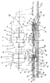
Weitere Einzelheiten und Vorteile der Erfindung ergeben sich aus den Ansprüchen und der nachfolgenden Beschreibung: Hierbei zeigt die einzige Figur eine Zweistationen-Blasformmaschine in Seitenansicht.Further details and advantages of the invention emerge from the claims and the following description: Here the single figure shows a two-station blow molding machine in side view.
In der einzigen Figur ist eine Zweistationen-Blasformmaschine mit einer
Schließeinheit 1 für die Formen zweier Werkzeuge 2, 3, mit einem einen Vorformlingsschlauch
bereitstellenden Extrusionskopf 4 und zwei unterhalb der Werkzeuge
angeordneten Blasdornvorrichtungen 5, 6 dargestellt. Das erste Werkzeug 2
umfaßt die beiden Blasformhälften 7, 8, das zweite Werkzeug 3 die beiden Blasformhälften
9, 10. Die Blasformhälften 7, 8, 9 und 10 sind lösbar an Formaufspannplatten
11 bis 14 befestigt. Jede Formaufspannplatte ist mit einem Joch 15,
17 bzw. mit einem Haltemittel 16 verbunden. Hierbei sind die Joche 15 und 17 der
äußeren Formaufspannplatten auf dem Rahmen eines Schlittens 18 horizontal
verfahrbar, während die inneren Formaufspannplatten 12, 13 über eine fest auf
dem Schlittenrahmen 18 angeordnete Säule 19 mit diesem verbunden sind.In the single figure is a two-station blow molding machine with one
Die Joche 15 bzw. 17 der beiden äußeren Formaufspannplatten 11 bzw. 14 sind
mit separaten Antriebsmitteln 20 bzw. 21 versehen. Hierzu ist jeweils eine durch
einen Motor 22 bzw. 23 angetriebene und in Lagern 24 bzw. 25 angeordnete
Spindel 26 bzw. 27 vorgesehen, die in einer Mutter 28 bzw. 29 läuft, die von einem
Tragarm 30 bzw. 31 aufgenommen wird. Der Tragarm 30 bzw. 31 greift an ein
Führungselement 32 bzw. 33 an, auf das ein Haltearm 34 bzw. 35 des Joches 15
bzw. 17 aufgesetzt ist.The
In axialer Verlängerung der beiden Antriebsspindeln 26, 27 sind zwei weitere
Muttern 36, 37 vorgesehen. Diese Muttern 36, 37 werden von einem Halteelement
38, 39 für den Blasdorn 40, 41 aufgenommen. Um Verkantungen bei der Bewegung
entlang des Schlittenrahmens zu vermeiden, weist jede Blasdornvorrichtung
5, 6 ebenfalls ein Führungselement 42, 43 auf. Für die Blasfunktion ist der jeweilige
Blasdorn 40, 41 vertikal in Richtung Werkzeuginneres verfahrbar.In axial extension of the two
Der Schlitten 18 ist horizontal mittels Rollen 44 bis 46 auf Führungsschienen 47
längs des Extrusionskopfes 4 verfahrbar. Der Schlitten 18 weist ein selbständiges
Antriebsaggregat 48 in Form einer durch einen Motor 49 angetriebenen Spindel 50
auf, die in Wirkverbindung mit einer fest verankerten Mutter 51 steht und die Rotation
der Spindel 50 in eine Längsbewegung des Schlittenrahmens umwandelt.The
In der einzigen Figur ist ein erstes Stadium mit geöffnetem ersten Werkzeug 2 und
geschlossenem Werkzeug 3 dargestellt sowie ein zweites Stadium mit geschlossenem
und verfahrenem ersten Werkzeug 2, hier in der Endposition strichpunktiert
gekennzeichnet.In the single figure is a first stage with the
In dem ersten Stadium wird in ein geöffnetes erstes Werkzeug 2, das sich unterhalb
des Extrusionskopfes 4 befindet, ein Vorformling (nicht gezeigt) eingeführt,
der auf dem Dorn 40 der Blasdornvorrichtung 5 plaziert wird. Anschließend wird
das Werkzeug 2 geschlossen, indem der Schlitten 18 und damit die fest plazierte
innere Formaufspannplatte 12 bzw. innere Blasformhälfte 7 bei dieser Ausführungsform
um einen halben Öffnungsweg ½ x verfahren wird. Zur Kompensation
des Schlittenweges wird die äußere Formaufspannplatte 11 anschließend um den
ganzen Öffnungsweg x in entgegengesetzte Richtung relativ zum Schlitten bzw.
die Blasdornvorrichtung 5 um den halben Öffnungsweg bewegt. Diese unterschiedlichen
Wegstrecken werden durch entsprechende Steigungen und Drehzahlen
der Antriebsspindel 50 des Schlittens 18 und der Antriebsspindel 26 der
äußeren Formaufspannplatte 11 erreicht, wobei die Steigung der Spindel der äußeren
Formaufspannplatte 11 um das doppelte größer ist als die Steigung der Antriebsspindel
des Schlittens bzw. die des Antriebsspindelbereichs der Blasdornvorrichtung.
Neben diesen nacheinander ablaufenden Bewegungsvorgängen ist es
auch vorteilhaft, wenn die Bewegungen nicht nacheinander, sondern gleichzeitig
ablaufen, um den Vorgang insgesamt zu beschleunigen.In the first stage, an opened
Im geschlossenen Zustand wird das erste Werkzeug 2 aus der Schlauchaufnahmeposition
durch Verfahren des Schlittens 18 in eine Blasstation oder Warteposition
gebracht. Der maximale Transportweg ist mit y bezeichnet. Das zweite Werkzeug
3 wird gleichzeitig in die Schlauchaufnahmestation gefahren, die gleichzeitig
die Artikelentnahmestation ist. Durch Verfahren der zweiten äußeren Formaufspannplatte
14 wird das Werkzeug 3 geöffnet und das fertige Kunststoffteil kann
entnommen werden.In the closed state, the
Claims (10)
dadurch gekennzeichnet,
daß die inneren Formaufspannplatten (12, 13) mittels eines Schlittens (18) verfahren werden, mit dem sie über ein Haltemittel (16) fest verbunden sind, während die Joche (15, 17) der äußeren Formaufspannplatten (11, 14) relativ zu dem Schlitten verfahren werden.Method for closing and opening the molds (2, 3) of a two-station plastic processing machine, in particular a blow molding machine, the tools (2, 3) in each of the two stations having two blow mold halves (7, 8, 9, 10) with mold mounting plates (11, 12, 13, 14) and the outer blow mold halves (8, 9) by means of drive means (20, 21), which are in operative connection with yokes (15, 17) of the outer mold mounting plates (11, 14), are displaced horizontally and thereby Blow mold halves (7, 8, 9, 10) are moved from an open position to receive a tubular preform below an extrusion head (4) into a closed position,
characterized,
that the inner platen (12, 13) are moved by means of a carriage (18) with which they are fixedly connected by a holding means (16), while the yokes (15, 17) of the outer platen (11, 14) relative to that Sledge to be moved.
dadurch gekennzeichnet,
daß ein Werkzeug (2, 3) aus einer geöffneten Position unterhalb des Extrusionskopfes (4) nach Aufnahme des Vorformlings in eine geschlossene Position durch Verschieben des Schlittens (18) um den Betrag eines halben Öffnungsweges und Verschieben des Joches (15, 17) der entsprechenden äußeren Formaufspannplatte (11, 14) des Werkzeugs in entgegengesetzter Richtung um den Betrag des ganzen Öffnungsweges verfahren wird. Method according to claim 1,
characterized,
that a tool (2, 3) from an open position below the extrusion head (4) after receiving the preform in a closed position by moving the carriage (18) by the amount of half an opening path and moving the yoke (15, 17) of the corresponding outer platen (11, 14) of the tool is moved in the opposite direction by the amount of the entire opening path.
dadurch gekennzeichnet,
daß eine Blasdornvorrichtung (5, 6) unterhalb des Werkzeugs (2, 3) so verschiebbar ist, daß sie sich stets unterhalb des Vorformlings befindet.Method according to claim 1,
characterized,
that a blow mandrel device (5, 6) below the tool (2, 3) is displaceable so that it is always below the preform.
mit
einer Schließeinheit (1) für zwei sich jeweils aus zwei Blasformhälften (7, 8, 9, 10) zusammensetzende Werkzeuge (2, 3) zur Aufnahme eines schlauchförmigen Vorformlings, wobei die Blasformhälften mit Formaufspannplatten (11, 12, 13, 14) versehen sind und die äußeren Blasformhälften mittels Antriebsmitteln (21, 22), die mit Jochen (15, 17) der äußeren Formaufspannplatten (11, 14) in Wirkverbindung stehen, horizontal verschiebbar sind,
einen Vorformlingsschlauch bereitstellenden Extrusionskopf (4) und mindestens einer unterhalb des Extrusionskopfes anzuordnender Blasdornvorrichtung (5, 6),
dadurch gekennzeichnet,
daß die Schließeinheit (1) auf einem Schlitten (18) angeordnet ist, der auf Linearführungen (47) läuft, sowie Antriebsmittel (48) aufweist,
daß auf diesem Schlitten ein Haltemittel (16) für die inneren, zueinander diametralen Formaufspannplatten (12, 13) fest angeordnet ist und daß der Schlitten (18) sowie die die äußeren Formaufspannplatten tragenden Joche (15, 17) relativ zueinander verfahrbar sind zur Einstellung einer Offenstellung und einer Schließposition des jeweiligen Werkzeugs jeweils unterhalb des Extrusionskopfes. Device for carrying out the method according to claims 1 to 3
With
a clamping unit (1) for two tools (2, 3), each composed of two blow mold halves (7, 8, 9, 10), for receiving a tubular preform, the blow mold halves being provided with mold mounting plates (11, 12, 13, 14) and the outer blow mold halves are horizontally displaceable by means of drive means (21, 22), which are operatively connected to yokes (15, 17) of the outer mold mounting plates (11, 14),
an extrusion head (4) providing a preform tube and at least one blow mandrel device (5, 6) to be arranged below the extrusion head,
characterized,
that the clamping unit (1) is arranged on a carriage (18) which runs on linear guides (47) and has drive means (48),
that on this carriage a holding means (16) for the inner, mutually diametrical platen (12, 13) is fixed and that the carriage (18) and the yoke carrying the outer platen (15, 17) are movable relative to each other for setting a Open position and a closed position of the respective tool below the extrusion head.
dadurch gekennzeichnet,
daß der Schlitten (18) und die Joche (15, 17) der äußeren Formaufspannplatten (11, 14) gemeinsame oder separate Antriebsmittel (21, 22, 48) aufweisen.Device according to claim 4,
characterized,
that the carriage (18) and the yokes (15, 17) of the outer platen (11, 14) have common or separate drive means (21, 22, 48).
dadurch gekennzeichnet,
daß das Antriebsmittel (48) des Schlittens (18) einen Motor (49) umfaßt, der ein Gewindespindel (50) in Rotation versetzt und daß die Gewindespindel mit einer stationären Mutter (51) in Wirkverbindung steht, so daß der Schlitten längs der Führung (47) verfahrbar ist.Device according to claims 4 and 5,
characterized,
that the drive means (48) of the carriage (18) comprises a motor (49) which rotates a threaded spindle (50) and that the threaded spindle is operatively connected to a stationary nut (51) so that the carriage along the guide ( 47) is movable.
dadurch gekennzeichnet,
daß für die Bewegung der Joche (15, 17) der äußeren Formaufspannplatten (11, 14) jeweils ein unabhängig arbeitender Motor (22, 23) über eine rotierende Gewindespindel (26, 27) mit einer Mutter (28, 29) so in Wirkverbindung steht, daß über die Joche die Halteplatten der äußeren Formaufspannplatten horizontal verschiebbar sind.Device according to claims 4 and 5,
characterized,
that for the movement of the yokes (15, 17) of the outer platen (11, 14) each an independently working motor (22, 23) via a rotating threaded spindle (26, 27) with a nut (28, 29) is in operative connection that the holding plates of the outer platen are horizontally displaceable over the yokes.
dadurch gekennzeichnet,
daß die Gewindespindeln (26, 27) zusätzlich mit einer Mutter (36, 37) der Blasdornvorrichtungen (5, 6) in Wirkverbindung stehen, die so verschoben werden, daß sie stets unterhalb des Vorformlings plaziert sind.Device according to claim 7,
characterized,
that the threaded spindles (26, 27) are also operatively connected to a nut (36, 37) of the blow mandrel devices (5, 6) which are displaced so that they are always placed below the preform.
dadurch gekennzeichnet,
daß die Steigung der Spindel in dem Wirkbereich der Muttern (28, 29) für die Formaufspannplatten doppelt so groß ist im Vergleich zu dem Spindelabschnitt, an dem die Muttern (36, 37) für die Blasdornvorrichtung angreifen.Device according to one of claims 6 to 8,
characterized,
that the pitch of the spindle in the effective area of the nuts (28, 29) for the mold mounting plates is twice as large as compared to the spindle section on which the nuts (36, 37) act for the blow mandrel device.
dadurch gekennzeichnet,
daß Führungsmittel (32, 33) an den Jochen der Formaufspannplatten bzw. der Blasdornvorrichtungen entlang des oberen Schlittenrahmens zur Verhinderung von Verkantungen vorgesehen sind.Device according to one of claims 4 to 9,
characterized,
that guide means (32, 33) are provided on the yokes of the platen or the blow mandrel devices along the upper slide frame to prevent canting.
Applications Claiming Priority (2)
| Application Number | Priority Date | Filing Date | Title |
|---|---|---|---|
| DE19927138 | 1999-06-15 | ||
| DE19927138A DE19927138C2 (en) | 1999-06-15 | 1999-06-15 | Method and device for closing and opening the molds of a plastic processing machine |
Publications (2)
| Publication Number | Publication Date |
|---|---|
| EP1060865A2 true EP1060865A2 (en) | 2000-12-20 |
| EP1060865A3 EP1060865A3 (en) | 2002-08-28 |
Family
ID=7911222
Family Applications (1)
| Application Number | Title | Priority Date | Filing Date |
|---|---|---|---|
| EP00106773A Withdrawn EP1060865A3 (en) | 1999-06-15 | 2000-03-30 | Process and device for opening and closing the moulds of a plastic moulding machine |
Country Status (3)
| Country | Link |
|---|---|
| US (1) | US6514452B1 (en) |
| EP (1) | EP1060865A3 (en) |
| DE (1) | DE19927138C2 (en) |
Cited By (6)
| Publication number | Priority date | Publication date | Assignee | Title |
|---|---|---|---|---|
| EP1306193A2 (en) * | 2001-10-24 | 2003-05-02 | Magic MP S.p.A. | Machine for blow-moulding containers made of plastic material, with actuating devices of the electric type |
| US7210755B2 (en) | 2000-06-16 | 2007-05-01 | Canon Kabushiki Kaisha | Solid semiconductor element, ink tank, ink jet recording apparatus provided with ink tank, liquid information acquiring method and liquid physical property change discriminating method |
| EP1884342A2 (en) * | 2006-08-03 | 2008-02-06 | BEKUM Maschinenfabriken GmbH | Device and method for blow moulding hollow thermoplastic bodies |
| WO2013007421A1 (en) * | 2011-07-13 | 2013-01-17 | Krones Ag | Blow-moulding machine for plastic containers |
| US9321229B2 (en) | 2011-07-13 | 2016-04-26 | Krones Ag | One-star system for feeding and discharging containers for processing machines |
| US9463591B2 (en) | 2011-04-13 | 2016-10-11 | Krones Ag | Container treatment machine and method of treating containers |
Families Citing this family (8)
| Publication number | Priority date | Publication date | Assignee | Title |
|---|---|---|---|---|
| ITBO20020618A1 (en) * | 2002-09-30 | 2004-04-01 | Sacmi | SINGLE MOLD MACHINE FOR PRESSURE CASTING |
| US7850443B2 (en) * | 2007-11-23 | 2010-12-14 | Dme Company Llc | Apparatus for injection molding |
| CN201357535Y (en) * | 2009-03-13 | 2009-12-09 | 苏州红枫风电模具有限公司 | Adjustable aligning device for large-sized combined type dies |
| WO2011127524A1 (en) * | 2010-04-12 | 2011-10-20 | Pro Technical Plastic Manufacturing Solutions Pty Ltd | A blow moulding machine and method of blow moulding |
| DE102012100161A1 (en) | 2012-01-10 | 2013-07-11 | Extraplast Maschinen Gmbh | Blow molding system and method for blow molding of hollow bodies |
| DE102012100156A1 (en) | 2012-01-10 | 2013-07-11 | Extraplast Maschinen Gmbh | Blow molding system and method for blow molding of hollow bodies |
| US10471644B2 (en) * | 2017-11-28 | 2019-11-12 | Weiler Engineering, Inc. | Blow molding apparatus |
| US10940634B2 (en) | 2018-10-05 | 2021-03-09 | Uniloy, Inc. | Blow molding apparatus and system |
Citations (5)
| Publication number | Priority date | Publication date | Assignee | Title |
|---|---|---|---|---|
| US3069722A (en) * | 1959-05-27 | 1962-12-25 | Kato Takeo | Blow moulder |
| DE9308467U1 (en) * | 1992-05-15 | 1993-08-19 | Mauser Werke Gmbh | Blow molding machine |
| US5681596A (en) * | 1996-03-06 | 1997-10-28 | Wilmington Machinery, Inc. | Dual parison stacked clamp blow molding apparatus |
| DE19747698A1 (en) * | 1996-11-15 | 1998-05-20 | Mauser Werke Gmbh | Blow moulding machine with independent drive for each tool half |
| DE19912116A1 (en) * | 1999-03-18 | 2000-09-21 | Kautex Maschinenbau Gmbh | Blow molding of hollow thermoplastic products from preforms using a closure frame with a central and two outer plates carrying molds with locking systems and a movement synchronizing mechanism |
Family Cites Families (6)
| Publication number | Priority date | Publication date | Assignee | Title |
|---|---|---|---|---|
| US5145353A (en) * | 1991-06-10 | 1992-09-08 | The Dow Chemical Company | Dual action molding press |
| DE9206649U1 (en) * | 1992-05-15 | 1993-09-16 | Mauser Werke Gmbh | Blow molding machine |
| US5551862A (en) * | 1994-06-06 | 1996-09-03 | Wilmington Machinery | Dual parison stacked clamp blow molding apparatus |
| US5753153A (en) * | 1996-01-02 | 1998-05-19 | Husky Injection Molding Systems Ltd. | Method for mold clamping units |
| IT1282432B1 (en) * | 1995-09-27 | 1998-03-23 | Sipa Spa | IMPROVED PLANT FOR THE PRODUCTION OF THERMOPLASTIC RESIN CONTAINERS |
| US6089852A (en) * | 1998-04-22 | 2000-07-18 | Tradesco Mold Limited | Mold centering arrangement for injection molding apparatus |
-
1999
- 1999-06-15 DE DE19927138A patent/DE19927138C2/en not_active Expired - Fee Related
-
2000
- 2000-03-30 EP EP00106773A patent/EP1060865A3/en not_active Withdrawn
- 2000-06-15 US US09/594,939 patent/US6514452B1/en not_active Expired - Fee Related
Patent Citations (5)
| Publication number | Priority date | Publication date | Assignee | Title |
|---|---|---|---|---|
| US3069722A (en) * | 1959-05-27 | 1962-12-25 | Kato Takeo | Blow moulder |
| DE9308467U1 (en) * | 1992-05-15 | 1993-08-19 | Mauser Werke Gmbh | Blow molding machine |
| US5681596A (en) * | 1996-03-06 | 1997-10-28 | Wilmington Machinery, Inc. | Dual parison stacked clamp blow molding apparatus |
| DE19747698A1 (en) * | 1996-11-15 | 1998-05-20 | Mauser Werke Gmbh | Blow moulding machine with independent drive for each tool half |
| DE19912116A1 (en) * | 1999-03-18 | 2000-09-21 | Kautex Maschinenbau Gmbh | Blow molding of hollow thermoplastic products from preforms using a closure frame with a central and two outer plates carrying molds with locking systems and a movement synchronizing mechanism |
Cited By (10)
| Publication number | Priority date | Publication date | Assignee | Title |
|---|---|---|---|---|
| US7210755B2 (en) | 2000-06-16 | 2007-05-01 | Canon Kabushiki Kaisha | Solid semiconductor element, ink tank, ink jet recording apparatus provided with ink tank, liquid information acquiring method and liquid physical property change discriminating method |
| EP1306193A2 (en) * | 2001-10-24 | 2003-05-02 | Magic MP S.p.A. | Machine for blow-moulding containers made of plastic material, with actuating devices of the electric type |
| EP1306193A3 (en) * | 2001-10-24 | 2003-10-15 | Magic MP S.p.A. | Machine for blow-moulding containers made of plastic material, with actuating devices of the electric type |
| US6884059B2 (en) | 2001-10-24 | 2005-04-26 | Magic Mp S.P.A. | Electrically actuated blow-moulding machine |
| EP1884342A2 (en) * | 2006-08-03 | 2008-02-06 | BEKUM Maschinenfabriken GmbH | Device and method for blow moulding hollow thermoplastic bodies |
| EP1884342A3 (en) * | 2006-08-03 | 2008-08-06 | BEKUM Maschinenfabriken GmbH | Device and method for blow moulding hollow thermoplastic bodies |
| US9463591B2 (en) | 2011-04-13 | 2016-10-11 | Krones Ag | Container treatment machine and method of treating containers |
| WO2013007421A1 (en) * | 2011-07-13 | 2013-01-17 | Krones Ag | Blow-moulding machine for plastic containers |
| US8939749B2 (en) | 2011-07-13 | 2015-01-27 | Krones Ag | Blow-molding machine for plastic containers |
| US9321229B2 (en) | 2011-07-13 | 2016-04-26 | Krones Ag | One-star system for feeding and discharging containers for processing machines |
Also Published As
| Publication number | Publication date |
|---|---|
| US6514452B1 (en) | 2003-02-04 |
| DE19927138C2 (en) | 2002-02-28 |
| DE19927138A1 (en) | 2001-01-04 |
| EP1060865A3 (en) | 2002-08-28 |
Similar Documents
| Publication | Publication Date | Title |
|---|---|---|
| DE19747698C2 (en) | blow molding machine | |
| DE19927138C2 (en) | Method and device for closing and opening the molds of a plastic processing machine | |
| EP1673208A1 (en) | Horizontal injection molding machine comprising a turning device | |
| EP0249703A2 (en) | Injection-moulding machine with at least two plasticising and injection units | |
| EP0895848A1 (en) | Method for producing injection moulded articles from at least two plastic melts | |
| DE3720214A1 (en) | INJECTION MOLDING MACHINE | |
| DE19932741C2 (en) | Method and device for closing and opening the tool of a plastics processing machine | |
| DE4138337C2 (en) | Method and device for producing laminated molded parts | |
| DE2911143A1 (en) | METHOD AND DEVICE FOR THE PRODUCTION OF HOLLOW BODIES, IN PARTICULAR PLASTIC BOTTLES | |
| DE102006028725A1 (en) | Process and system for post-treatment of preforms | |
| DE4223314A1 (en) | Opening and closing mechanism for blow mould tools - has mould clamping plates with extensions mounted on columns and spindles which have specific type drive for precise linear movements | |
| DE3529775C2 (en) | ||
| DE19922684C2 (en) | Blow molding machine for low-waste blowing | |
| EP0853537A2 (en) | Mould closure unit with a device for removing injection mouldings | |
| WO2006084668A1 (en) | Injection moulding machine for processing plastic materials | |
| WO2002057062A1 (en) | Ejector device for a moulding machine | |
| DE2161247C3 (en) | Device for producing hollow bodies | |
| DE102007049655B4 (en) | Corrugator device with demoulding device | |
| EP0734837A1 (en) | Apparatus for transporting a parison from an annular die to a blow mould of a blow moulding machine | |
| DE19503386C2 (en) | Handling device for a machine tool, in particular an injection molding machine | |
| EP1048435A1 (en) | Injection blow moulding process and device | |
| AT411522B (en) | injection molder | |
| DE3249540C2 (en) | Horizontal mould clamping unit for a plastics injection moulding machine | |
| DE19925325A1 (en) | Clamping unit for a plastics molding machine, especially an injection machine, has rods connected between a rotating plate and moving platen to effect clamping force | |
| DE10051265A1 (en) | Injection molding machine for making semi-finished plastic bottles has horizontal rotating mounting which carries molds for forming neck and thread |
Legal Events
| Date | Code | Title | Description |
|---|---|---|---|
| PUAI | Public reference made under article 153(3) epc to a published international application that has entered the european phase |
Free format text: ORIGINAL CODE: 0009012 |
|
| AK | Designated contracting states |
Kind code of ref document: A2 Designated state(s): AT BE CH CY DE DK ES FI FR GB GR IE IT LI LU MC NL PT SE |
|
| AX | Request for extension of the european patent |
Free format text: AL;LT;LV;MK;RO;SI |
|
| RAP1 | Party data changed (applicant data changed or rights of an application transferred) |
Owner name: SIG KAUTEX GMBH & CO.KG |
|
| PUAL | Search report despatched |
Free format text: ORIGINAL CODE: 0009013 |
|
| AK | Designated contracting states |
Kind code of ref document: A3 Designated state(s): AT BE CH CY DE DK ES FI FR GB GR IE IT LI LU MC NL PT SE |
|
| AX | Request for extension of the european patent |
Free format text: AL;LT;LV;MK;RO;SI |
|
| 17P | Request for examination filed |
Effective date: 20030220 |
|
| 17Q | First examination report despatched |
Effective date: 20030318 |
|
| AKX | Designation fees paid |
Designated state(s): AT BE CH CY DE DK ES FI FR GB GR IE IT LI LU MC NL PT SE |
|
| GRAP | Despatch of communication of intention to grant a patent |
Free format text: ORIGINAL CODE: EPIDOSNIGR1 |
|
| STAA | Information on the status of an ep patent application or granted ep patent |
Free format text: STATUS: THE APPLICATION IS DEEMED TO BE WITHDRAWN |
|
| 18D | Application deemed to be withdrawn |
Effective date: 20040210 |