EP1059571A2 - Coupling member, process cartridge and image forming apparatus - Google Patents
Coupling member, process cartridge and image forming apparatus Download PDFInfo
- Publication number
- EP1059571A2 EP1059571A2 EP00304813A EP00304813A EP1059571A2 EP 1059571 A2 EP1059571 A2 EP 1059571A2 EP 00304813 A EP00304813 A EP 00304813A EP 00304813 A EP00304813 A EP 00304813A EP 1059571 A2 EP1059571 A2 EP 1059571A2
- Authority
- EP
- European Patent Office
- Prior art keywords
- coupling member
- main assembly
- drive transmission
- driving force
- driving
- Prior art date
- Legal status (The legal status is an assumption and is not a legal conclusion. Google has not performed a legal analysis and makes no representation as to the accuracy of the status listed.)
- Granted
Links
Images


Classifications
-
- G—PHYSICS
- G03—PHOTOGRAPHY; CINEMATOGRAPHY; ANALOGOUS TECHNIQUES USING WAVES OTHER THAN OPTICAL WAVES; ELECTROGRAPHY; HOLOGRAPHY
- G03G—ELECTROGRAPHY; ELECTROPHOTOGRAPHY; MAGNETOGRAPHY
- G03G21/00—Arrangements not provided for by groups G03G13/00 - G03G19/00, e.g. cleaning, elimination of residual charge
- G03G21/16—Mechanical means for facilitating the maintenance of the apparatus, e.g. modular arrangements
- G03G21/18—Mechanical means for facilitating the maintenance of the apparatus, e.g. modular arrangements using a processing cartridge, whereby the process cartridge comprises at least two image processing means in a single unit
- G03G21/1839—Means for handling the process cartridge in the apparatus body
- G03G21/1857—Means for handling the process cartridge in the apparatus body for transmitting mechanical drive power to the process cartridge, drive mechanisms, gears, couplings, braking mechanisms
- G03G21/186—Axial couplings
-
- G—PHYSICS
- G03—PHOTOGRAPHY; CINEMATOGRAPHY; ANALOGOUS TECHNIQUES USING WAVES OTHER THAN OPTICAL WAVES; ELECTROGRAPHY; HOLOGRAPHY
- G03G—ELECTROGRAPHY; ELECTROPHOTOGRAPHY; MAGNETOGRAPHY
- G03G15/00—Apparatus for electrographic processes using a charge pattern
-
- G—PHYSICS
- G03—PHOTOGRAPHY; CINEMATOGRAPHY; ANALOGOUS TECHNIQUES USING WAVES OTHER THAN OPTICAL WAVES; ELECTROGRAPHY; HOLOGRAPHY
- G03G—ELECTROGRAPHY; ELECTROPHOTOGRAPHY; MAGNETOGRAPHY
- G03G15/00—Apparatus for electrographic processes using a charge pattern
- G03G15/06—Apparatus for electrographic processes using a charge pattern for developing
- G03G15/08—Apparatus for electrographic processes using a charge pattern for developing using a solid developer, e.g. powder developer
- G03G15/0822—Arrangements for preparing, mixing, supplying or dispensing developer
- G03G15/0877—Arrangements for metering and dispensing developer from a developer cartridge into the development unit
- G03G15/0881—Sealing of developer cartridges
- G03G15/0882—Sealing of developer cartridges by a peelable sealing film
-
- G—PHYSICS
- G03—PHOTOGRAPHY; CINEMATOGRAPHY; ANALOGOUS TECHNIQUES USING WAVES OTHER THAN OPTICAL WAVES; ELECTROGRAPHY; HOLOGRAPHY
- G03G—ELECTROGRAPHY; ELECTROPHOTOGRAPHY; MAGNETOGRAPHY
- G03G21/00—Arrangements not provided for by groups G03G13/00 - G03G19/00, e.g. cleaning, elimination of residual charge
- G03G21/16—Mechanical means for facilitating the maintenance of the apparatus, e.g. modular arrangements
- G03G21/18—Mechanical means for facilitating the maintenance of the apparatus, e.g. modular arrangements using a processing cartridge, whereby the process cartridge comprises at least two image processing means in a single unit
- G03G21/1839—Means for handling the process cartridge in the apparatus body
- G03G21/1857—Means for handling the process cartridge in the apparatus body for transmitting mechanical drive power to the process cartridge, drive mechanisms, gears, couplings, braking mechanisms
- G03G21/1864—Means for handling the process cartridge in the apparatus body for transmitting mechanical drive power to the process cartridge, drive mechanisms, gears, couplings, braking mechanisms associated with a positioning function
-
- G—PHYSICS
- G03—PHOTOGRAPHY; CINEMATOGRAPHY; ANALOGOUS TECHNIQUES USING WAVES OTHER THAN OPTICAL WAVES; ELECTROGRAPHY; HOLOGRAPHY
- G03G—ELECTROGRAPHY; ELECTROPHOTOGRAPHY; MAGNETOGRAPHY
- G03G2215/00—Apparatus for electrophotographic processes
- G03G2215/08—Details of powder developing device not concerning the development directly
- G03G2215/0875—Arrangements for shipping or transporting of the developing device to or from the user
- G03G2215/0877—Sealing of the developing device opening, facing the image-carrying member
- G03G2215/088—Peelable sealing film
-
- G—PHYSICS
- G03—PHOTOGRAPHY; CINEMATOGRAPHY; ANALOGOUS TECHNIQUES USING WAVES OTHER THAN OPTICAL WAVES; ELECTROGRAPHY; HOLOGRAPHY
- G03G—ELECTROGRAPHY; ELECTROPHOTOGRAPHY; MAGNETOGRAPHY
- G03G2221/00—Processes not provided for by group G03G2215/00, e.g. cleaning or residual charge elimination
- G03G2221/16—Mechanical means for facilitating the maintenance of the apparatus, e.g. modular arrangements and complete machine concepts
- G03G2221/18—Cartridge systems
- G03G2221/183—Process cartridge
Definitions
- the present invention relates to a coupling member and a process cartridge, which are usable for an image forming apparatus. It also relates to an image forming apparatus.
- a motor gear 26a integral with the output shaft of the motor 26, rotates.
- the first coupling 43 in the image forming apparatus main assembly moves in the direction of an arrow mark D while rotating in the direction of an arrow mark C, without coupling with the first driving force transmission coupling 44, with which one of the longitudinal ends of the photosensitive drum 11 in the process cartridge 15 is provided. Therefore, the photosensitive drum 11 does not rotate in the direction reverse to the normal direction.
Abstract
Description
- The present invention relates to a coupling member and a process cartridge, which are usable for an image forming apparatus. It also relates to an image forming apparatus.
- In this specification, the term "image forming apparatus" means an apparatus for forming an image on recording medium, using a given image forming method, preferably, an electrophotographic image forming method. As for examples of such an image forming apparatus, there are electrophotographic copying machines, electrophotographic printers (laser beam printers, LED printers, and the like), facsimile apparatuses, word processors, and the like.
- The term "process cartridge" means a cartridge which is removably installable in the main assembly of an image forming apparatus, and in which at least one means among a charging means, a developing means, and a cleaning means, and an image bearing member, are integrally disposed.
- Conventionally, an image forming apparatus which employs an electrophotographic image formation process also employs a process cartridge system, according to which an electrophotographic photosensitive member as an image bearing member, and one or a plurality of processing means which act on the electrophotographic photosensitive member, are integrated into the form of a cartridge, which is removably installable in the main assembly of an image forming apparatus. Also according to this process cartridge system, an image forming apparatus can be maintained by a user alone, without relying on a service person, drastically improving operational efficiency. Therefore, a process cartridge system has been widely used in the field of an image forming apparatus.
- A process cartridge such as the one described above comprises one or a plurality of processing means. One of such processing means is a developing means, which integrally comprises a developer storage container (toner container) in which toner is stored, and a developing means frame for supporting a developing member. Until a process cartridge is put to use for the first time, the passage between the toner container and developing means frame remains sealed with a sealing member (toner seal). This sealing member is torn open when a process cartridge is put to use for the first time.
- It is common knowledge that some process cartridges or electrophotographic image forming apparatuses (hereinafter, "image forming apparatus"), are provided with a driving force transmitting means for receiving the driving force from the main assembly of an image forming apparatus to automatically wind up the sealing member to tear open it.
- The sealing member winding driving force transmitting means of a conventional image forming apparatus, process cartridge, or toner container, is structured so that as the winding of the sealing member ends, it must stop transmitting the driving force, or it shuts down. Therefore, an apparatus main assembly, process cartridge, or toner container, must be provided with a driving force transmitting means dedicated to the winding of a sealing member. Further, in many image forming apparatus main assemblies, a toner seal winding unit and a toner stirring unit are simultaneously driven.
- Such an arrangement complicates the driving means on the apparatus main assembly side. Further, the simultaneous driving of the stirring unit and toner seal winding unit leads to increase in power consumption.
- The present invention is one of the results of the further development of the above described conventional technologies.
- As a mean for solving the above described problems, it was conceivable to divide a driving force transmitting portion into a two portions, that is, a portion for transmitting driving force to a photosensitive drum and a toner stirring member, and a portion for transmitting driving force to a sealing member winding unit, and to begin driving the photosensitive drum and toner stirring member after finishing driving the toner seal winding unit. In addition to the above described problems, a conventional structure suffers another problem. That is, when a sealing member begins to be wound, the process cartridge is yet to be securely positioned relative to the apparatus main assembly, and therefore, while the sealing member is wound to be torn open, the process cartridge is sometimes caused to vibrate by the driving force from the image forming apparatus main assembly.
- As the process cartridge vibrates, the coupling member on the process cartridge side, through which the electrophotographic photosensitive drum is driven by the driving force from the image forming apparatus main assembly, fails to align with the coupling member on the image forming apparatus main assembly side, making it difficult for the coupling member on the cartridge side to be inserted into the coupling member on the main assembly side.
- The primary object of the present invention is to provide a driving force transmitting coupling member, a process cartridge, and an image forming apparatus, which make it possible to approximately fix the positional relationship between a driving force transmitting coupling member and a coupling member on the main assembly side when the driving force transmitting coupling member transmits driving force to a driving means for tearing open a sealing member.
- Another object of the present invention is to provide a driving force transmitting coupling member, a process cartridge, and an image forming apparatus, which make it possible to virtually unfix the previously fixed positional relationship between a driving force transmitting coupling member and a coupling member on the main assembly side when a driving force transmitting coupling member transmits driving force to a stirring member.
- Another object of the present invention is to provide a coupling member for driving a driving means which does not cause a process cartridge to vibrate when a sealing member is torn open, and allows the coupling member on the image forming apparatus main assembly side to easily engage with the coupling member of an image bearing member after the completion of the tearing of the sealing member, and driving a driving means for a stirring member, a process cartridge comprising such a coupling member, and an image forming apparatus in which such a process cartridge is removably installable.
- These and other objects, features, and advantages of the present invention will become more apparent upon consideration of the following description of the preferred embodiments of the present invention, taken in conjunction with the accompanying drawings.
-
- Figure 1 is a schematic sectional view of the essential portion of the process cartridge in the preferred embodiment of the present invention, at a plane perpendicular to the longitudinal direction of the cartridge.
- Figure 2 is a schematic sectional view of the essential portion of the image forming apparatus in the preferred embodiment of the present invention, at a plane perpendicular to the longitudinal direction of the process cartridge.
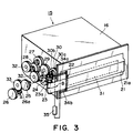
- Figure 3 is a schematic perspective view of the toner storage container of the process cartridge in the first embodiment of the present invention which is in the brand-new condition.
- Figure 4 is a schematic perspective view of the toner storage container of the process cartridge in the first embodiment of the present invention, from which the toner seal has been wound away.
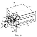
- Figure 5 is a schematic perspective view of the toner storage container of the process cartridge in the first embodiment, in which the toner stirring member has begun to be rotated.
- Figure 6 is a schematic perspective view of the process cartridge in the first embodiment, when the toner seal is being wound.
- Figure 7 is a schematic perspective view of the process cartridge in the first embodiment, when the photosensitive drum and stirring member are being rotated.
- Figure 8 is a schematic perspective view of the first coupling of the process cartridge, and the first coupling of the image forming apparatus main assembly, in the first embodiment.
- Figure 9 is a sectional view of a combination of the second coupling of the process cartridge and the second coupling of the image forming apparatus main assembly, in the first embodiment, at a plane perpendicular to the axial lines of the two coupling members, when the two couplings are rotating in the direction to tear open the toner seal.
- Figure 10 is a sectional view of a combination of the second coupling of the process cartridge and the second coupling of the image forming apparatus main assembly, in the first embodiment, at a plane perpendicular to the axial lines of the two coupling members, when the two couplings are rotating in the direction to drive the stirring member.
- Figure 11 is a flow chart for the first embodiment.
- Figure 12 is an abbreviated circuit diagram for the first embodiment.
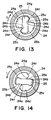
- Figure 13 is a sectional view of a combination of the second coupling of the process cartridge and the second coupling of the image forming apparatus main assembly, in the second embodiment, at a plane perpendicular to the axial lines of the two coupling members, when the two couplings are rotating in the direction to tear open the toner seal.
- Figure 14 is a sectional view of a combination of the second coupling of the process cartridge and the second coupling of the image forming apparatus main assembly, in the second embodiment, at a plane perpendicular to the axial lines of the two coupling members, when the two couplings are rotating in the direction to drive the stirring member.
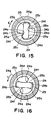
- Figure 15 is a sectional view of a combination of the second coupling of the process cartridge and the second coupling of the image forming apparatus main assembly, in the third embodiment, at a plane perpendicular to the axial lines of the two coupling members, when the two couplings are rotating in the direction to tear open the toner seal.
- Figure 16 is a sectional view of a combination of the second coupling of the process cartridge and the second coupling of the image forming apparatus main assembly, in the third embodiment, at a plane perpendicular to the axial lines of the two coupling members, when the two couplings are rotating in the direction to drive the stirring member.
-
- Hereinafter, preferred embodiments of the present invention will be described with reference to Figures 1 and 2.
- Figure 1 illustrates a cross section of the essential portion of a process cartridge in accordance with the present invention, at a plane perpendicular to the longitudinal direction of the cartridge. Figure 2 illustrates a cross section of the essential portion of an image forming apparatus in accordance with the present invention, at a plane perpendicular to the longitudinal direction of the process cartridge. This process cartridge is provided with an image bearing member and one or a plurality of processing means which act on the image bearing member. As for the processing means, there are, for example, a charging means for charging the peripheral surface of the image bearing member, a developing apparatus for forming a toner image on the image bearing member, and a cleaning means for removing the toner remaining on the peripheral surface of the image forming apparatus. The process cartridge is provided with an electrophotographic photosensitive member as the image bearing member, and at least one processing means among the above listed processing means.
- Referring to Figure 1, in the case of the
process cartridge 15 in this embodiment, acharging roller 12 as the charging means, adevelopment roller 18 and a development blade, which constitute the developing apparatus, atoner storage frame 16 as a developer storage container in which toner as developer is stored, a stirringmember 20 as a rotational member for stirring the toner in thetoner storage frame 16, acleaning blade 14 as the cleaning means, and an electrophotographic photosensitive drum 11, along the peripheral surface of which the preceding processing means are disposed, are integrally disposed in a housing to form theprocess cartridge 15 removably installable in the main assembly of an image forming apparatus. - This
process cartridge 15 is installed into an image forming apparatus C illustrated in Figure 2 to be used for image formation, which is carried out through the following steps. First, a sheet S is conveyed to an image transfer location adjacent to the peripheral surface of the photosensitive drum 11, from asheet cassette 6 installed in the bottom portion of the image forming apparatus C, by apickup roller 4, a pair of conveyer rollers 7, and aregistration roller 5. Meanwhile, the photosensitive drum 11 is selectively exposed to light modulated with image information by anexposing apparatus 8 after being charged by thecharge roller 12. As a result, an electrostatic latent image is formed. The exposure by theexposing apparatus 8 is carried out in synchronism with the sheet conveyance by theregistration roller 5. After the formation of the electrostatic latent image, the toner which has been delivered into the developingmeans frame 17 from thetoner storage frame 16 is coated in a thin layer on the peripheral surface of thedevelopment roller 18 by thedevelopment blade 19. As development bias is applied to thedevelopment roller 18, the toner is supplied from thedevelopment roller 18 to the photosensitive drum 11 in a pattern correspondent to the pattern of the electrostatic latent image, forming a toner image on the photosensitive drum 11. This toner image is transferred onto the sheet S, which is being conveyed, by applying bias (voltage) to thetransfer roller 9 at the transfer location. Thereafter, the sheet S is conveyed to afixing apparatus 10, in which the toner image is fixed to the sheet S, and then, the sheet S is discharged by a pair ofdischarge rollers 1, into adelivery portion 2 located at the top of the image forming apparatus. - Referring to Figure 1, the above described
process cartridge 15 comprises thetoner storage frame 16, the developingmeans frame 17, and the cleaning meansframe 13, which are sandwiched by a pair of side covers 36 as shown in Figure 6. Thetoner storage frame 16 contains thetoner stirring member 20, and thetoner delivery opening 31 of which is sealed with atoner sealing member 21. The developing meansframe 17 supports thedevelopment roller 18 anddevelopment blade 19. The cleaning meansframe 13 supports thecleaning blade 14, and also pivotally supports the developingmeans frame 17. The side covers 36 cover the entire longitudinal ends of thetoner storage frame 16, developingmeans frame 17, and cleaning meansframe 13. - The
toner storage frame 16 and developingmeans frame 17 are connected to each other, with thetoner delivery opening 31 of thetoner storage frame 16 and the toner receiving opening of the developingmeans frame 17 connected by aflexible sealing member 37, forming an airtight passage between the twoframes - Figures 3 to 5 depict the toner storage frame in accordance with the present invention, and Figures 6 and 7 depict the process cartridge and the gear train within the image forming apparatus main assembly. Referring to Figure 3, in the case of a brand-new process cartridge, the
opening 31 of thetoner storage frame 16 for supplying toner into the developingmeans frame 17 is covered with thetoner sealing member 21, which is welded or glued to thetoner storage frame 16 in a manner to cover theopening 31. The oneend 21a of thetoner sealing member 21 is folded back at a line slightly outward beyond the welding line, is extended back across theopening 31, and is fixed to the round shaft of a winding member rotatably supported by thetoner storage frame 16. The width of the folded-back portion of thetoner sealing member 21 is narrower than the width of the portion of thetoner sealing member 21 welded or glued to thetoner storage frame 16 in a manner to cover theopening 31. - The
toner sealing member 21 is provided with an electricallyconductive portion 22, which is laid across the electrically nonconductive polyethylene terephthalate portion of thetoner sealing member 21, to detect whether or not theopening 31 has been entirely exposed; theconductive portion 22 is laid across the downstream side of thetoner sealing member 21 in terms of the direction in which thetoner sealing member 21 is torn. In this embodiment, theconductive portion 22 is a piece of aluminum foil pasted to the toner sealing member, across the downstream side of thetoner sealing member 21 in terms of the tearing direction of thetoner sealing member 21. Across thisconductive portion 22, voltage is applied from the detecting portion of the image forming apparatus main assembly. More specifically, theprocess cartridge 15 is provided with a metallic plate equipped with a pair ofcontacts conductive portion 22 through this metallic plate. - As the
process cartridge 15 in the brand-new condition is installed into the image forming apparatus main assembly, the detectingportion 35 andconductive portion 22 are electrically connected through thecontacts toner sealing member 21 is almost completely wound up, electrical current is allowed to conduct through theconductive portion 22, and is detected by the detectingportion 35 of the image forming apparatus main assembly. Upon detection of this current flow through the conductive portion, amotor 26 provided as a driving force source on the image forming apparatus main assembly side begins to rotate in the direction indicated by an arrow mark A. - Referring to Figure 6, the image forming apparatus main assembly is provided with the
motor 26, anidler gear 42, afirst coupling 43, anidler gear 33, and asecond coupling 25. - Referring to Figures 3 and 6, as the
motor 26 rotates in the direction of the arrow mark A, amotor gear 26a, integral with the output shaft of themotor 26, rotates. Upon receiving the rotational force transmitted from themotor gear 26a through theidler gear 42, thefirst coupling 43 in the image forming apparatus main assembly moves in the direction of an arrow mark D while rotating in the direction of an arrow mark C, without coupling with the first drivingforce transmission coupling 44, with which one of the longitudinal ends of the photosensitive drum 11 in theprocess cartridge 15 is provided. Therefore, the photosensitive drum 11 does not rotate in the direction reverse to the normal direction. The second driving forcetransmission coupling gear 24 in theprocess cartridge 15 receives driving force by engaging with thesecond coupling 25 on the image forming apparatus main assembly side, to which the driving force is transmitted from themotor 26 of the image forming apparatus main assembly through theidler gear 33. The second driving forcetransmission coupling gear 24 transmits the driving force to anoscillatory gear 29, with which theprocess cartridge 15 is provided, and which is illustrated in Figure 3, which shows thetoner storage frame 16 from which the pair of side covers 36 have been removed. Upon the transmission of the driving force to thisoscillatory gear 29, theoscillatory gear 29 moves toward theidler gear 30, and meshes therewith, transmitting thereby the driving force thereto. As a result, thegear 23a of the windingmember 23, which is in mesh with theidler gear 30, rotates, causing thetoner sealing member 21 to be wound in the direction of an arrow mark B. At this point, theoscillatory gear 29 is not in mesh with anoscillatory idler gear 27; there is a gap between the two oscillatory gears. - The
oscillatory gear 29 is rotatably supported by the end portion of an unillustrated oscillatory arm axially attached to thetoner storage frame 16, in such a manner that the center of theoscillatory gear 29 is on a line perpendicular to the line which connects the centers of theoscillatory idler gear 27 andidler gear 30. The oscillatory axis of the oscillatory arm coincides with the rotational axis of the second driving forcetransmission coupling gear 24. When not in operation, the oscillatory gear is retained where it does not mesh with either of theoscillatory idler gear 27 andidler gear 30, by pulling the oscillatory arm with the use of a pair of springy members which pull the oscillatory arm in opposing directions. Theoscillatory gear 29 is in mesh with thegear portion 24g (Figures 9 and 10), that is, the peripheral portion, of thesecond coupling gear 24. In other words, the inward portion of thesecond coupling 24 constitutes the actual coupling portion, and the peripheral portion of thesecond coupling gear 24 constitutes thegear portion 24a. - Thus, as the
second coupling gear 24 rotates in the clockwise direction as shown in Figure 3, theoscillatory gear 29 pivots about the same axis as thesecond coupling gear 24 due to the tooth load between thegear portion 24a of thesecond coupling gear 24, and theoscillatory gear 29, and meshes with theidler gear 30 which drives the windinggear 23a. As thesecond coupling gear 24 stops, theoscillatory gear 29 is retracted from theidler gear 30 by the aforementioned springy members; the meshing between theoscillatory gear 29 andidler gear 30 is disengaged. - Referring to Figure 5, as the
second coupling gear 24 rotates in the counterclockwise direction (direction of arrow mark I), theoscillatory gear 29 pivots about the same axis as thesecond coupling gear 24 due to the tooth load between thegear portion 24g of thesecond coupling gear 24 and theoscillatory gear 29, and meshes with theoscillatory idler gear 27 for transmitting the driving force to thestirring gear 32. - The
oscillatory idler gear 27 is a compound gear integrally comprising a pair of gears different in diameter, the smaller of which is meshed with anidler gear 28. Theidler gear 28 is also a compound gear integrally comprising a pair of gears different in diameter, the smaller of which is meshed with the stirringgear 32. - The idler gears 27 and 28, and the
stirring gear 32, are individually and rotatably attached to one of the side walls of the developingmeans frame 17. The stirringgear 32 is connected to thetoner stirring member 20. - The above does not means that the means for changing the direction in which the
oscillatory gear 29 pivots, in accordance with rotational direction in which thecoupling gear 24 rotates, is limited to the above described means. - The
idler gear 30 is rotatably supported by thetoner storage frame 16 of theprocess cartridge 15. Theidler gear 30 is a compound gear integrally comprising aspur gear 30a, with or from which theoscillatory gear 29 engages or disengages, and abevel gear 30b, which meshes with thebevel gear 23a integral with the windingmember 23. - Referring to Figure 4, as the
toner sealing member 21 is wound in the direction of the arrow mark B, theconductive portion 22 is severed after theopening 31 is fully exposed. Consequently, the electrical connection between thecontacts contacts portion 35 of the image forming apparatus main assembly, the CPU (Figure 12) of the image forming apparatus main assembly controls the motor driving portion so that themotor 26, which has been supplying thesecond coupling 25 on the main assembly side with the force for driving the windingmember 23, rotates in reverse. Next, referring to Figure 7, as themotor 26 rotates in reverse, that is, in the direction of an arrow mark F, the first coupling 34 on the image forming apparatus main assembly side moves in the direction of an arrow mark H while remaining in mesh with theidler gear 42 and rotating in the direction of an arrow mark G, couples with the first drivingforce transmission coupling 44, with which one of the longitudinal ends of the photosensitive drum 11 in theprocess cartridge 15 is provided, and rotates while remaining coupled with the first drivingforce transmission coupling 44, to transmit the driving force to the photosensitive drum 11. - Referring back to Figure 5, the second driving
force transmission coupling 24 in theprocess cartridge 15 also rotates in reverse. As a result, theoscillatory gear 29 moves away from theidler gear 30, becoming disengaged therefrom, and engages with theoscillatory idler gear 27, causing theoscillatory idler gear 27 to rotate, which in turn transmits, through theidler gear 28, the driving force to thestirring gear 32 for rotating the stirringmember 20 in thetoner storage frame 16 shown in Figure 1. - Here, referring to Figures 8 to 10, the configurations of the couplings will be described.
- Referring to Figure 8, the first driving
force transmission coupling 44 is provided with aprojection 44a which is approximately in the form of a triangular prism, more specifically, a triangular prism twisted about its rotational axis in its rotational direction. Thefirst coupling 43 on the main assembly side is provided with a recess which is approximately in the form of a triangular prism twisted about its rotational axis, and in which theprojection 44a engages. With this arrangement, as the first drivingforce transmission coupling 44 fits into thefirst coupling 43 on the main assembly side, and is rotated thereby, the edges of theprojection 44a make contact with the interior surfaces of therecess 43a, one for one, simultaneously and in the same manner. Therefore, the axial lines of the two couplings become aligned with each other while transmitting driving force. - Since the coupling portion of the
first coupling 44, and the coupling portion of thecoupling 43 on the main assembly side, are constituted of a projection and a recess, respectively, in the form of a twisted triangular prism, the rotation of thefirst coupling 44 after its engagement with thecoupling portion 43 generates thrust in their axial direction. More specifically, referring to Figure 6, as thefirst coupling 43 on the main assembly side rotates in the direction of the arrow mark C, it is moved in the direction of the arrow mark D. Referring to Figure 7, as thefirst coupling 43 on the main assembly side rotates in the direction of the arrow mark G after its engagement with thefirst coupling 44, it is moved in the direction of the arrow mark H by being pulled by thefirst coupling 44 because of their twisted shape. - As is evident from the above description, as the first coupling on the main assembly side rotates in the direction of the arrow mark C, it does not remain engaged with the
first coupling 44, and therefore, the two couplings are not positioned relative to each other in any specific manner. On the other hand, as thefirst coupling 43 on the main assembly side rotates in the direction of the arrow mark G, it engages with thefirst coupling 44, with a progressively increasing margin, while establishing proper positional relationship relative to thefirst coupling 44. - Next, referring to Figures 9 and 10, the
second coupling 25 on the image forming apparatus main assembly side is provided with a projection in the form of a flatted round column, and the portions adjacent to the two parallel edges of each of the pair of flat surfaces of this projection constitute a pair ofcontact portions contact portions second coupling 25. On the other hand, thesecond coupling gear 24 in theprocess cartridge 15 is provided with acylindrical recess 24d, and the wall of thecylindrical recess 24 is provided with an opposing pair of right-angled ribs. The surfaces of each rib, which are perpendicular to each other, constituteflat contact portions - Referring to Figure 9, as the
second coupling 25 on the main assembly side rotates in therecess 24d of thesecond coupling gear 24, in the direction of an arrow mark E to tear open the toner seal, thecontact portions 24a of the angular ribs of thesecond coupling gear 24 and thecontact portions 25a of thecoupling 25 come into contact with each other, whereby the driving force is transmitted. - Also referring to Figure 9, in order to reduce the
gap 40, which is formed between the surface of therecess 24d of thesecond coupling gear 24 and the correspondent curved surface of the projection of thesecond coupling 25 on the main assembly side, in terms of the radial direction of the twocouplers second coupling 25 on the main assembly side rotates in therecess 24d of thesecond coupling gear 24, in the direction of the arrow mark E to tear open the toner seal, and thecontact portions 24a of the angular ribs of thesecond coupling gear 24 and thecontact portions 25a of thecoupling 25 come into contact with each other, the twoportions 24e of the surface of therecess 24d, which oppose each other with respect to the axial line of thecoupling 24, and face the opposing curved surfaces of the projection of thesecond coupling 25, one for one, after the contact between the corresponding contact portions of thecouplers - In cross section, the pair of opposing
curved portion 25d (surfaces) of thesecond coupling 25 on the main assembly side, form an arc, which is included in a circle, the center of which coincides with the rotational axis of thesecond coupling 25 on the main assembly side. Further, the two virtuallyflat surfaces 24e of the recess 23d of thesecond coupling 24 are an equal distance away from the rotational axis of thesecond coupling 24. - In this embodiment, the gap between the
second coupling gear 24, and thesecond coupling 25 on the main assembly side, in terms of the radial direction of the two couplings, is made to be approximately 0.5 mm. Next, referring to Figure 10, as the driving for tearing open thetoner sealing member 21 ends, thesecond coupling 25 on the main assembly side rotates in reverse in the direction of the arrow mark I, causing thecontact portions 24b of thesecond coupling gear 24 to come in contact with thecontact portion 25b of the second coupling on the main assembly side. As a result, thesecond coupling gear 24 is driven, and the driving force is transmitted to thetoner stirring member 20. Further, the twocouplings second coupling gear 24 in the direction of the arrow mark I by thesecond coupling 25 on the apparatus main assembly side, there will be agap 41 between the two couplings in terms of the radial direction of their rotational axes. In this embodiment, this gap is approximately 2 mm. - With the provision of the above structural arrangement, while the
toner sealing member 21 is torn open, the positions of the rotational axes of thesecond coupling 25 on the main assembly side andsecond coupling gear 24 are stabilized virtually in alignment with each other, without rotationally driving the photosensitive drum 11. During the period after thetoner sealing member 21 is torn open, that is, during image formation, the rotational axis of thefirst coupling 44 with which the photosensitive drum 11 is provided, and the rotational axis of thefirst coupling 43 on the main assembly side, become the primary rotational axes, and therefore, even when the rotational axis of thesecond coupling 24 for transmitting the driving force to the stirringmember 20, and the rotational axis of thesecond coupling 25 on the main assembly side, are deviated from each other, the aligning of these two axes does not occur. Thus, the driving force is transmitted to the second coupling for driving the stirringmember 20, without interfering with the aligning of the rotational axis of thefirst coupling 43 on the main assembly side and the rotational axis of thefirst coupling 44. In other words, it is permitted that the rotational axis of thesecond coupling 44 and the rotational axis of thefirst coupling 43 become misaligned with each other. - The above described operation may be summarized in the form of a flow chart given in Figure 11. Figure 12 shows the abbreviated diagram of the circuit which controls the operation.
- Upon installation of the process cartridge in this embodiment into the image forming apparatus, it is confirmed in step S1 whether or not current is allowed to flow through the conductive portion. When current flow is detected, step S2 is taken, in which the winding of the
toner sealing member 21 is started. Next, in step S3, the tearing of thetoner sealing member 21 continues, and eventually, theconductive portion 22 is severed. In step S4, the severing of theconductive portion 22 is detected, and therefore, it is determined that the tearing of thetoner sealing member 22 has been completed. Next, in step S5, themotor 26 within the image forming apparatus main assembly is rotated in reverse to begin rotating thetoner stirring member 20. - The detecting
portion 35 comprises a DC power source and a current monitor. It applies voltage from the power source, and measures the current by the monitor to detect whether or not thetoner sealing member 21 has been completely torn open. - Referring to Figures 13 and 14, this embodiment is different from the first embodiment in terms of the configuration of the contacting surfaces of the second coupling gear and the second coupling on the main assembly side. Otherwise, this embodiment is identical to the first embodiment. Thus, only the contact surfaces in this embodiment will be described below.
- The
second coupling 25 on the image forming apparatus main assembly side is provided with a projection in the form of a flatted round column. This projection is provided with a pair ofribs 25c, which are approximately semicircular in cross section, and symmetrical to each other with respect to the rotational axis of thesecond coupling 25 on the main assembly side. On the other hand, thesecond coupling 24 of theprocess cartridge 15 is provided with acylindrical recess 24d, the cylindrical wall of which is provided with a pair of opposing, approximately right-angled ribs, which are symmetrical with respect to the rotational axis of thesecond coupling gear 24. These ribs are provided withcontact portions contact portions contact portions second coupling 24f. Bothcontact portions 24a are provided with arecess 24f which is approximately semicircular in cross section. - Referring to Figure 13, as the
second coupling 25 rotates in the direction of the arrow mark E, that is, the direction to tear open the toner seal, theribs 25c, that is, the contact portions of thecoupling 25, which are approximately semicircular in cross section, engage in therecesses 24f with which the angular ribs of thesecond coupling gear 24 are provided, and transmits the driving force. - As the
second coupling gear 24 rotates in the direction of the arrow mark E, that is, the direction to tear open thetoner sealing member 21, theribs 25c which are approximately semicircular in cross section, and with which thecoupling 25 on the main assembly side is provided, engages in therecesses 24f which are approximately semicircular in cross section, and with which the angular ribs of thesecond coupling gear 24 are provided. As a result, the movement of the twocouplings coupling - As the
ribs 25c engage into therecesses 24f, thecontact portion 25a of thesecond coupling 25 on the main assembly side comes into, and remains in, contact with thecontact portion 24a of thesecond coupling gear 24, transmitting the rotational force, or the driving force, from thesecond coupling 25 on the main assembly side to thesecond coupling gear 24. It should be noted here that instead of making thecontact portions rib 25c may be placed in contact with the surface of thecorrespondent recess 24f. - Referring to Figure 14, after the completion of the drive for tearing open the
toner sealing member 21, thesecond coupling 25 on the main assembly side is rotated in reverse in the direction of the arrow mark I, causing thecontact portion 24b of thesecond coupling gear 24 to come into contact with thecontact portion 25b of thesecond coupling 25 on the main assembly side. As a result, thesecond coupling gear 24 is driven to transmit the driving force to the stirringmember 20. - Referring to Figures 15 and 16, the second coupling gear, and the second coupling gear on the main assembly side, in this embodiment, which will be described below, are different in configuration from those in the second embodiment. Otherwise, this embodiment is identical in configuration to the second embodiment. More specifically, while the coupling portions in the second embodiment are approximately semicircular in cross section, the coupling portions in this third embodiment are rendered approximately triangular in cross section.
- The
second coupling 25 on the image forming apparatus main assembly side is provided with a projection in the form of a flatted round column. This projection is provided with a pair ofribs 25c which are approximately triangular in cross section. Thesecond coupling gear 24 within theprocess cartridge 15 is provided with acylindrical recess 24d, the cylindrical wall of which is provided with a pair of ribs, which are approximately triangular in cross section, with the surfaces of each rib serving ascontact portions - Referring to Figure 15, as the
second coupling 25 on the main assembly side is rotated in the direction of the arrow mark E, that is, the direction to tear open thetoner sealing member 21, theribs 25c of thesecond coupling 25 on the main assembly side engage into therecesses 24f of thesecond coupling gear 24, transmitting the driving force. - While the
second coupling gear 24 is rotationally driven in the direction of the arrow mark E, that is, the direction to tear open thetoner sealing member 21, theribs 25c which are triangular in cross section, and with which thesecond coupling 25 on the main assembly side, engage into, and remain in, therecesses 24f which are triangular in cross section, and with which thesecond coupling gear 24 is provided. As a result, the movement of thesecond coupling gear 24 in terms of the radial direction is regulated, and the rotational axes of the twocouplings - As the
ribs 25c engage into therecesses 24f, thecontact portion 25a of thesecond coupling 25 on the main assembly side comes into, and remains in, contact with thecontact portion 24a of thesecond coupling gear 24, transmitting the rotational force, or the driving force, from thesecond coupling 25 on the main assembly side to thesecond coupling gear 24. It should be noted here that instead of making thecontact portions rib 25c may be placed in contact with the surface of thecorrespondent recess 24f. - Referring to Figure 16, after the completion of the drive for tearing open the
toner sealing member 21, thesecond coupling 25 on the main assembly side is rotated in reverse in the direction of the arrow mark I, causing thecontact portion 24b of thesecond coupling gear 24 to come into contact with thecontact portion 25b of thesecond coupling 25 on the main assembly side. As a result thesecond coupling gear 24 is driven to transmit the driving force to the stirringmember 20. - As described regarding the first to third embodiments, according to the present invention, while the sealing member is torn open, the positional relationship between the second driving force transmission coupling, and the second coupling on the main assembly side, is virtually fixed, and remains virtually fixed, preventing a process cartridge from vibrating. Further, during this tearing of the toner sealing member, the first driving force transmission coupling, and the first coupling on the main assembly side, for transmitting driving force to an image bearing member, are not engaged with each other, and therefore, it does not occur that the image bearing member is rotated in reverse. In other words, during this period, the process cartridge is positioned at a position different from the position for image formation.
- Further, when driving force is transmitted to a stirring member, the first driving force transmission coupling, and the first coupling on the main assembly side, are engaged with each other, and are fixed in positional relationship relative to each other. Therefore, the process cartridge is prevented from vibrating. Also during this period, the process cartridge is placed in the position for image formation. Further, when the positional relationship between the first driving force transmission coupling, and the first coupling on the main assembly side, changes from the unengaged state to the engaged state, a certain amount of deviation is permitted between the rotational axis of the second driving force transmission coupling, and the rotational axis of the second coupling on the main assembly side. Therefore, the change of the positional relationship between the first driving force transmission coupling, and the first coupling on the main assembly side, from the unengaged state to the engaged state, is smooth.
- While the invention has been described with reference to the structures disclosed herein, it is not confined to the details set forth, and this application is intended to cover such modifications or changes as may come within the purposes of the improvements or the scope of the following claims.
Claims (31)
- A rotatable coupling member for transmitting driving forces to first driving means for driving a seal member for sealing an opening for discharging a developer from a developer accommodating container for accommodating the developer to unseal the opening and to second driving means for driving a stirring member for stirring the developer in the developer accommodating container,
wherein said drive transmission coupling member receives the driving force from a main assembly coupling member provided in a main assembly of an image forming apparatus to rotate in a first rotational direction to unseal the opening and to rotate in a second rotational direction which is opposite from the first rotational direction to drive said second driving means, said drive transmission coupling member comprising:a first portion for substantially aligning a rotational center of said drive transmission coupling member with a rotational center of the main assembly coupling member when said drive transmission coupling member rotates in the first rotational direction, anda second portion for permitting deviation between the rotational center of said drive transmission coupling member and the rotational center of the main assembly coupling member. - A drive transmission coupling member according to Claim 1, wherein a relative positional relation of the drive transmission coupling member relative to the main assembly coupling member is different between when it rotates in the first rotational direction and when it rotates in the second rotational direction.
- A drive transmission coupling member according to Claim 1, wherein said drive transmission coupling member is provided with a first driving force receiving portion for receiving the driving force from the main assembly coupling member and a second driving force receiving portion for receiving the driving force from the main assembly coupling member when it rotates in the second rotational direction.
- A drive transmission coupling member according to Claim 1, wherein a gap in a radial direction between said drive transmission coupling member and the main assembly coupling member is larger when it rotates in the second rotational direction than when it rotates in the first rotational direction.
- A drive transmission coupling member according to Claim 1, wherein said first portion is engaged with the main assembly coupling member.
- A drive transmission coupling member according to Claim 5, wherein the first portion includes a substantially semicircular portion.
- A drive transmission coupling member according to Claim 5, wherein said first portion includes a substantially triangular portion.
- A process cartridge detachably mountable to a main assembly of an image forming apparatus, comprising:an image bearing member;a developing device for developing an electrostatic image formed on a image bearing member with a developer, said developing device including a developer accommodating container, provided with an opening for discharging the developer, for discharging the developer, a seal member for sealing the opening, a stirring member for stirring the developer in the developer accommodating container, a first driving means for removing the seal member and a second driving means for driving the stirring member;a rotatable first drive transmission coupling member for receiving a driving force from a first main assembly coupling member provided in the main assembly of the apparatus to transmit the driving force to said image bearing member;a rotatable second drive transmission coupling member for receiving a driving force from a second main assembly coupling member provided in the main assembly of the apparatus to transmit the driving forces to said first and second driving means;
wherein one said second drive transmission coupling member transmits the driving force to said first driving means to unseal the opening, a rotational center of said second drive transmission coupling member and a rotational center of said second main assembly coupling member are substantially aligned, and the drive transmission between the first drive transmission coupling member and the first main assembly coupling member is disabled, and after the opening is unsealed, said second drive transmission coupling member transmits the driving force to said second driving means, and the rotational center of the second drive transmission coupling member and the rotational center of the second main assembly coupling member are permitted to deviate, and said first drive transmission coupling member receives driving force from said first main assembly coupling member. - A process cartridge according to Claim 8, wherein said second drive transmission coupling member transmit the driving force to said first driving means by rotating in a first rotational direction and transmits the driving force to said second driving means by rotating in a second rotational direction which is opposite from the first rotational direction, wherein said second drive transmission coupling member comprises a first portion for substantially aligning a rotational center of said second drive transmission coupling member with a rotational center of the second main assembly coupling member when it rotates in the first rotational direction and a second portion for permitting deviation between the rotational center of said second drive transmission coupling member and the rotational center of the second main assembly coupling member.
- A process cartridge according to Claim 9, wherein a relative positional relation of the second drive transmission coupling member relative to the second main assembly coupling member is different between when it rotates in the first rotational direction and when it rotates in the second rotational direction.
- A process cartridge according to Claim 9, wherein said second drive transmission coupling member is provided with a first driving force receiving portion for receiving the driving force from the second main assembly coupling member and a second driving force receiving portion for receiving the driving force from the second main assembly coupling member when it rotates in the second rotational direction.
- A process cartridge according to Claim 9, wherein a gap in a radial direction between said second drive transmission coupling member and the second main assembly coupling member is larger when it rotates in the second rotational direction when it rotates in the first rotational direction.
- A process cartridge according to Claim 9, wherein said first portion is engaged with the main assembly coupling member.
- A process cartridge according to Claim 13, wherein the first portion includes a substantially semicircular portion.
- A process cartridge according to Claim 13, wherein wherein said first portion includes a substantially triangular portion.
- An image forming apparatus to which a process cartridge is detachably mountable, said apparatus comprising:a process cartridge mounting member for mounting said process cartridge, which includes:an image bearing member;a developing device for developing an electrostatic image formed on a image bearing member with a developer, said developing device including a developer accommodating container, provided with an opening for discharging the developer, for discharging the developer, a seal member for sealing the opening, a stirring member for stirring the developer in the developer accommodating container, a first driving means for removing the seal member and a second driving means for driving the stirring member;a rotatable first drive transmission coupling member for receiving a driving force from a first main assembly coupling member provided in the main assembly of the apparatus to transmit the driving force to said image bearing member;a rotatable second drive transmission coupling member for receiving a driving force from a second main assembly coupling member provided in the main assembly of the apparatus to transmit the driving forces to said first and second driving means;said apparatus further comprising:a first main assembly coupling member for supplying a driving force to said first drive transmission coupling member;a second main assembly coupling member for supplying a driving force to said second drive transmission coupling member;
wherein one said second drive transmission coupling member transmits the driving force to said first driving means to unseal the opening, a rotational center of said second drive transmission coupling member and a rotational center of said second main assembly coupling member are substantially aligned, and the drive transmission between the first drive transmission coupling member and the first main assembly coupling member is disabled, and after the opening is unsealed, said second drive transmission coupling member transmits the driving force to said second driving means, and the rotational center of the second drive transmission coupling member and the rotational center of the second main assembly coupling member are permitted to deviate, and said first drive transmission coupling member receives driving force from said first main assembly coupling member. - An apparatus according to Claim 16, wherein said second drive transmission coupling member transmit the driving force to said first driving means by rotating in a first rotational direction and transmits the driving force to said second driving means by rotating in a second rotational direction which is opposite from the first rotational direction, wherein said second drive transmission coupling member comprises a first portion for substantially aligning a rotational center of said second drive transmission coupling member with a rotational center of the second main assembly coupling member when it rotates in the first rotational direction and a second portion for permitting deviation between the rotational center of said second drive transmission coupling member and the rotational center of the second main assembly coupling member.
- An apparatus according to Claim 17, wherein a relative positional relation of the second drive transmission coupling member relative to the second main assembly coupling member is different between when it rotates in the first rotational direction and when it rotates in the second rotational direction.
- An apparatus according to Claim 17, wherein said second drive transmission coupling member is provided with a first driving force receiving portion for receiving the driving force from the second main assembly coupling member and a second driving force receiving portion for receiving the driving force from the second main assembly coupling member when it rotates in the second rotational direction.
- An apparatus according to Claim 17, wherein a gap in a radial direction between said second drive transmission coupling member and the second main assembly coupling member is larger when it rotates in the second rotational direction when it rotates in the first rotational direction.
- An apparatus according to Claim 17, wherein said first portion is engaged with the main assembly coupling member.
- An apparatus according to Claim 21, wherein the first portion includes a substantially semicircular portion.
- An apparatus according to Claim 21, wherein said first portion includes a substantially triangular portion.
- A drive transmission coupling comprising:a male coupling member having first and second oppositely-facing radially-extending surfaces;a female coupling member having first and second oppositely-facing radially-extending surfaces;the respective first radially-extending surfaces of the male and female coupling members being cooperable when the male and female coupling members are in a first relative angular relationship for transmitting drive torque in a first rotary direction;the respective second radially-extending surfaces of the male and female coupling members being cooperable when the male and female coupling members in a second relative angular relationship for transmitting drive torque in a second rotary direction; and
wherein engagement means are operative between the first and second coupling members to prevent relative movement of the male and female coupling members in a radial direction when the first and second coupling members are in the said second relative angular relationship. - A drive coupling according to claim 24, wherein the male and female coupling members each have a pair of first radially-extending surfaces and a pair of second radially-extending surfaces.
- A drive coupling according to claim 24 or claim 25, wherein the engagement means comprises a circumferentially-extending projection and a cooperating recess formed on the respective second radially-extending surfaces of the male and female coupling members.
- A drive coupling according to claim 24 or claim 25, wherein the engagement means comprises cooperating respective external and internal circumferentially-extending surfaces of the male and female coupling members situated adjacent the radially outer ends of the respective second radially-extending surfaces.
- A male coupling member for a drive coupling according to any of claims 24 to 27.
- A female coupling member for a drive coupling according to any of claims 24 to 27.
- A process cartridge detachably mountable to a main assembly of an image forming apparatus and including a drive coupling member according to claim 28 or claim 29 for receiving a driving torque from said main assembly.
- A process cartridge detachably mountable to a main assembly of an image forming apparatus and including:a toner accommodating container having an opening for discharging the toner and a seal member for sealing the opening;a stirring member for stirring the toner in the toner accommodating container;a first drive coupling member for receiving a rotary drive in first and second driving directions from a cooperating second drive coupling member of said main assembly;first transmission means for transmitting driving force in a first rotary driving direction from the drive coupling member to a first driving means for removing the seal member from the opening;second transmission means for transmitting driving force in a second rotary driving direction from the drive coupling member to a second driving means for driving the stirring member; and
wherein the first drive coupling member includes engagement means cooperable with engagement means of the second drive coupling member to maintain the first and second drive coupling members in a coaxial relation when transmitting driving force in the first rotary driving direction.32. An electrophotographic image forming apparatus for detachably receiving a process cartridge according to claim 30 or claim 31, and including a drive coupling member for a drive coupling according to any of claims 24 to 27.
Applications Claiming Priority (2)
| Application Number | Priority Date | Filing Date | Title |
|---|---|---|---|
| JP16047299 | 1999-06-08 | ||
| JP16047299A JP3943761B2 (en) | 1999-06-08 | 1999-06-08 | Process cartridge and electrophotographic image forming apparatus |
Publications (3)
| Publication Number | Publication Date |
|---|---|
| EP1059571A2 true EP1059571A2 (en) | 2000-12-13 |
| EP1059571A3 EP1059571A3 (en) | 2002-01-16 |
| EP1059571B1 EP1059571B1 (en) | 2005-06-01 |
Family
ID=15715703
Family Applications (1)
| Application Number | Title | Priority Date | Filing Date |
|---|---|---|---|
| EP00304813A Expired - Lifetime EP1059571B1 (en) | 1999-06-08 | 2000-06-07 | Coupling member, process cartridge and image forming apparatus |
Country Status (6)
| Country | Link |
|---|---|
| US (1) | US6301457B1 (en) |
| EP (1) | EP1059571B1 (en) |
| JP (1) | JP3943761B2 (en) |
| KR (1) | KR100368094B1 (en) |
| CN (1) | CN1139012C (en) |
| DE (1) | DE60020452T2 (en) |
Cited By (4)
| Publication number | Priority date | Publication date | Assignee | Title |
|---|---|---|---|---|
| EP1168100A2 (en) * | 2000-06-26 | 2002-01-02 | Canon Kabushiki Kaisha | Toner seal member, development cartridge, process cartridge and electrophotographic image forming apparatus |
| EP1253485A2 (en) | 2001-04-27 | 2002-10-30 | Canon Kabushiki Kaisha | Process cartridge, electrophotographic image forming apparatus and fixing method of electrical contact part |
| EP2202588A1 (en) * | 2008-12-23 | 2010-06-30 | Sagem Communications Sas | Printing unit |
| EP2711782A3 (en) * | 2012-09-25 | 2017-03-15 | Kyocera Document Solutions Inc. | Image forming apparatus, toner case and drive transmission mechanism |
Families Citing this family (32)
| Publication number | Priority date | Publication date | Assignee | Title |
|---|---|---|---|---|
| JP3442047B2 (en) * | 2000-11-17 | 2003-09-02 | キヤノン株式会社 | Process cartridge and electrophotographic image forming apparatus |
| JP2002214896A (en) | 2001-01-19 | 2002-07-31 | Canon Inc | Developer container, process cartridge and electrophotographic image forming apparatus |
| JP3564080B2 (en) | 2001-04-27 | 2004-09-08 | キヤノン株式会社 | Process cartridge remanufacturing method |
| JP3542569B2 (en) | 2001-04-27 | 2004-07-14 | キヤノン株式会社 | Process cartridge remanufacturing method |
| JP2003255806A (en) * | 2002-02-28 | 2003-09-10 | Canon Inc | Process cartridge, developing device, and image forming apparatus |
| JP3677506B2 (en) * | 2002-08-07 | 2005-08-03 | 株式会社リコー | Belt drive control method and apparatus, belt apparatus, image forming apparatus, process cartridge, program, and recording medium |
| JP3919779B2 (en) * | 2003-08-29 | 2007-05-30 | キヤノン株式会社 | Electrophotographic image forming apparatus |
| JP3997213B2 (en) * | 2004-03-31 | 2007-10-24 | キヤノン株式会社 | Electrophotographic image forming apparatus |
| JP3984978B2 (en) * | 2004-07-06 | 2007-10-03 | キヤノン株式会社 | Process cartridge and electrophotographic image forming apparatus |
| US20060008289A1 (en) * | 2004-07-06 | 2006-01-12 | Canon Kabushiki Kaisha | Electrophotographic image forming apparatus and process cartridge |
| JP3970279B2 (en) * | 2004-07-30 | 2007-09-05 | キヤノン株式会社 | Process cartridge and electrophotographic image forming apparatus |
| JP4695913B2 (en) * | 2005-04-12 | 2011-06-08 | キヤノン株式会社 | Electrophotographic image forming apparatus |
| KR100729618B1 (en) * | 2005-10-04 | 2007-06-19 | 삼성전자주식회사 | Driving apparatus, process cartridge and image forming device having the same |
| JP4946157B2 (en) * | 2006-05-02 | 2012-06-06 | 富士ゼロックス株式会社 | Image forming unit |
| JP4364214B2 (en) * | 2006-05-13 | 2009-11-11 | 村田機械株式会社 | Drive transmission mechanism and image forming apparatus using the same |
| JP4464435B2 (en) | 2006-12-11 | 2010-05-19 | キヤノン株式会社 | Process cartridge and electrophotographic image forming apparatus |
| JP4665927B2 (en) * | 2007-03-27 | 2011-04-06 | ブラザー工業株式会社 | Cartridge and image forming apparatus |
| KR100781364B1 (en) * | 2007-05-02 | 2007-11-30 | 삼성전자주식회사 | driving apparatus, process cartridge and image forming device having the same |
| JP5219626B2 (en) * | 2008-05-27 | 2013-06-26 | キヤノン株式会社 | Process cartridge and image forming apparatus |
| JP4869289B2 (en) * | 2008-05-27 | 2012-02-08 | キヤノン株式会社 | Process cartridge and electrophotographic image forming apparatus |
| JP5344538B2 (en) * | 2008-05-27 | 2013-11-20 | キヤノン株式会社 | Process cartridge assembling method, process cartridge disassembling method, process cartridge remanufacturing method, and process cartridge |
| JP5517732B2 (en) | 2010-05-11 | 2014-06-11 | キヤノン株式会社 | Process cartridge and image forming apparatus |
| JP5517989B2 (en) | 2010-05-14 | 2014-06-11 | キヤノン株式会社 | Process cartridge and image forming apparatus |
| JP5943685B2 (en) | 2012-04-13 | 2016-07-05 | キヤノン株式会社 | Developing unit, process cartridge, and electrophotographic image forming apparatus |
| JP6723694B2 (en) | 2015-07-01 | 2020-07-15 | キヤノン株式会社 | Image forming apparatus and cartridge |
| JP6665635B2 (en) * | 2016-03-31 | 2020-03-13 | ブラザー工業株式会社 | Developing cartridge |
| CN107305338B (en) * | 2016-04-19 | 2024-01-16 | 纳思达股份有限公司 | Process cartridge and process cartridge assembling method |
| EP3455678A1 (en) * | 2016-05-10 | 2019-03-20 | Clover Technologies Group, LLC | Remanufactured toner cartridge and test method therefor |
| ES2896765T3 (en) | 2016-06-14 | 2022-02-25 | Canon Kk | Process cartridge and electrophotographic imaging device |
| TWI638247B (en) * | 2017-08-15 | 2018-10-11 | 上福全球科技股份有限公司 | Toner cartridge |
| JP7047695B2 (en) | 2018-09-28 | 2022-04-05 | ブラザー工業株式会社 | Develop cartridge |
| KR20220033679A (en) * | 2020-09-10 | 2022-03-17 | 휴렛-팩커드 디벨롭먼트 컴퍼니, 엘.피. | Connection structure for coupling with toner cartridge |
Citations (6)
| Publication number | Priority date | Publication date | Assignee | Title |
|---|---|---|---|---|
| GB768997A (en) * | 1953-07-09 | 1957-02-27 | Frank R Ford Ltd | Improvements relating to rotary motion transmission couplings for duplicating machines |
| JPH01193872A (en) * | 1988-01-29 | 1989-08-03 | Canon Inc | Image forming device provided with process cartridge |
| US4998140A (en) * | 1987-09-17 | 1991-03-05 | Sharp Kabushiki Kaisha | Developing device for copier with sealing means |
| JPH0990724A (en) * | 1995-09-26 | 1997-04-04 | Ricoh Co Ltd | Toner vessel |
| EP0833230A2 (en) * | 1996-09-26 | 1998-04-01 | Canon Kabushiki Kaisha | Process cartridge and electrophotographic image forming apparatus |
| JPH11119535A (en) * | 1997-10-20 | 1999-04-30 | Fuji Xerox Co Ltd | Detachable developer storage case and developing device |
Family Cites Families (5)
| Publication number | Priority date | Publication date | Assignee | Title |
|---|---|---|---|---|
| JPH096214A (en) * | 1995-06-19 | 1997-01-10 | Canon Inc | Process cartridge, supply cartridge, and image forming device |
| JPH09114352A (en) * | 1995-10-16 | 1997-05-02 | Canon Inc | Process cartridge and image forming device |
| JPH10222041A (en) | 1996-12-03 | 1998-08-21 | Canon Inc | Process cartridge and electrophotographic image forming device |
| JP3363727B2 (en) | 1996-12-12 | 2003-01-08 | キヤノン株式会社 | Process cartridge, electrophotographic image forming apparatus, process cartridge assembling method, and waste toner container assembling method |
| JP3083091B2 (en) * | 1997-12-09 | 2000-09-04 | キヤノン株式会社 | Seal member for developer storage container, developer storage container, developing device, process cartridge, and image forming apparatus |
-
1999
- 1999-06-08 JP JP16047299A patent/JP3943761B2/en not_active Expired - Fee Related
-
2000
- 2000-06-06 US US09/587,912 patent/US6301457B1/en not_active Expired - Lifetime
- 2000-06-07 EP EP00304813A patent/EP1059571B1/en not_active Expired - Lifetime
- 2000-06-07 DE DE60020452T patent/DE60020452T2/en not_active Expired - Lifetime
- 2000-06-07 KR KR10-2000-0030943A patent/KR100368094B1/en not_active IP Right Cessation
- 2000-06-08 CN CNB001181254A patent/CN1139012C/en not_active Expired - Fee Related
Patent Citations (6)
| Publication number | Priority date | Publication date | Assignee | Title |
|---|---|---|---|---|
| GB768997A (en) * | 1953-07-09 | 1957-02-27 | Frank R Ford Ltd | Improvements relating to rotary motion transmission couplings for duplicating machines |
| US4998140A (en) * | 1987-09-17 | 1991-03-05 | Sharp Kabushiki Kaisha | Developing device for copier with sealing means |
| JPH01193872A (en) * | 1988-01-29 | 1989-08-03 | Canon Inc | Image forming device provided with process cartridge |
| JPH0990724A (en) * | 1995-09-26 | 1997-04-04 | Ricoh Co Ltd | Toner vessel |
| EP0833230A2 (en) * | 1996-09-26 | 1998-04-01 | Canon Kabushiki Kaisha | Process cartridge and electrophotographic image forming apparatus |
| JPH11119535A (en) * | 1997-10-20 | 1999-04-30 | Fuji Xerox Co Ltd | Detachable developer storage case and developing device |
Non-Patent Citations (3)
| Title |
|---|
| PATENT ABSTRACTS OF JAPAN vol. 013, no. 488 (P-954), 7 November 1989 (1989-11-07) & JP 01 193872 A (CANON INC), 3 August 1989 (1989-08-03) * |
| PATENT ABSTRACTS OF JAPAN vol. 1997, no. 08, 29 August 1997 (1997-08-29) & JP 09 090724 A (RICOH CO LTD), 4 April 1997 (1997-04-04) * |
| PATENT ABSTRACTS OF JAPAN vol. 1999, no. 09, 30 July 1999 (1999-07-30) & JP 11 119535 A (FUJI XEROX CO LTD), 30 April 1999 (1999-04-30) * |
Cited By (7)
| Publication number | Priority date | Publication date | Assignee | Title |
|---|---|---|---|---|
| EP1168100A2 (en) * | 2000-06-26 | 2002-01-02 | Canon Kabushiki Kaisha | Toner seal member, development cartridge, process cartridge and electrophotographic image forming apparatus |
| EP1168100A3 (en) * | 2000-06-26 | 2009-02-04 | Canon Kabushiki Kaisha | Toner seal member, development cartridge, process cartridge and electrophotographic image forming apparatus |
| EP1253485A2 (en) | 2001-04-27 | 2002-10-30 | Canon Kabushiki Kaisha | Process cartridge, electrophotographic image forming apparatus and fixing method of electrical contact part |
| EP1253485A3 (en) * | 2001-04-27 | 2007-05-30 | Canon Kabushiki Kaisha | Process cartridge, electrophotographic image forming apparatus and fixing method of electrical contact part |
| EP2388661A1 (en) * | 2001-04-27 | 2011-11-23 | Canon Kabushiki Kaisha | Process cartridg and fixing method of electrical contact part |
| EP2202588A1 (en) * | 2008-12-23 | 2010-06-30 | Sagem Communications Sas | Printing unit |
| EP2711782A3 (en) * | 2012-09-25 | 2017-03-15 | Kyocera Document Solutions Inc. | Image forming apparatus, toner case and drive transmission mechanism |
Also Published As
| Publication number | Publication date |
|---|---|
| KR100368094B1 (en) | 2003-01-15 |
| EP1059571B1 (en) | 2005-06-01 |
| DE60020452T2 (en) | 2006-05-04 |
| CN1139012C (en) | 2004-02-18 |
| JP2000347487A (en) | 2000-12-15 |
| US6301457B1 (en) | 2001-10-09 |
| JP3943761B2 (en) | 2007-07-11 |
| EP1059571A3 (en) | 2002-01-16 |
| KR20010020956A (en) | 2001-03-15 |
| CN1276543A (en) | 2000-12-13 |
| DE60020452D1 (en) | 2005-07-07 |
Similar Documents
| Publication | Publication Date | Title |
|---|---|---|
| EP1059571B1 (en) | Coupling member, process cartridge and image forming apparatus | |
| US9523942B2 (en) | Developer accommodating container, developing cartridge, process cartridge and image forming apparatus | |
| US9069289B2 (en) | Developer container, developing cartridge, process cartridge and image forming apparatus | |
| US9229371B2 (en) | Developer container, developing cartridge, process cartridge and image forming apparatus | |
| US9188906B2 (en) | Cartridge, developing cartridge, process cartridge and image forming apparatus | |
| JP3950568B2 (en) | Developer container, developing device, process cartridge, and image forming apparatus | |
| EP0871092B1 (en) | Toner frame, process cartridge and image forming apparatus | |
| US9291942B2 (en) | Developer accommodating unit, process cartridge and image forming apparatus | |
| US7231164B2 (en) | Developing unit, developing cartridge, and image forming apparatus | |
| JPH10105026A (en) | Process cartridge and electrophotographic image forming device | |
| EP1107073B1 (en) | Image forming apparatus with controlled drive source for removal of a sealing member in a developing cartridge | |
| JP2002182446A (en) | Driving force transmission component, electrophotograhic photoreceptor drum, process cartridge and electrophotographic image forming device | |
| JP3507372B2 (en) | Developing device, process cartridge, and electrophotographic image forming device | |
| JP4035552B2 (en) | Developer container, developing device, process cartridge, and image forming apparatus | |
| KR20050118353A (en) | Developer driving device and image-forming apparatus using the same | |
| JP3814524B2 (en) | Powder container, developing device including the same, and electrophotographic image forming apparatus | |
| JPH09288425A (en) | Automatic toner seal opening device, process cartridge and electrophotographic image forming device | |
| JP3984984B2 (en) | Developing device, process cartridge, and electrophotographic image forming apparatus | |
| JP4677113B2 (en) | Electrophotographic image forming apparatus | |
| JP2003307925A (en) | Developing cartridge | |
| JP2021099407A (en) | Drive transmission structure, developer container, and image forming apparatus | |
| JP2001305839A (en) | Method for assembling toner seal winding member, developer container, develop cartridge, process cartridge, electronic image forming device, and toner seal member with toner seal winding member | |
| JP2002268347A (en) | Development cartridge, process cartridge and electrophotographic imaging device | |
| JPH11258964A (en) | Electrophotographic image forming device | |
| JPH11249497A (en) | Process cartridge |
Legal Events
| Date | Code | Title | Description |
|---|---|---|---|
| PUAI | Public reference made under article 153(3) epc to a published international application that has entered the european phase |
Free format text: ORIGINAL CODE: 0009012 |
|
| AK | Designated contracting states |
Kind code of ref document: A2 Designated state(s): CH DE FR GB IT LI Kind code of ref document: A2 Designated state(s): AT BE CH CY DE DK ES FI FR GB GR IE IT LI LU MC NL PT SE |
|
| AX | Request for extension of the european patent |
Free format text: AL;LT;LV;MK;RO;SI |
|
| PUAL | Search report despatched |
Free format text: ORIGINAL CODE: 0009013 |
|
| AK | Designated contracting states |
Kind code of ref document: A3 Designated state(s): AT BE CH CY DE DK ES FI FR GB GR IE IT LI LU MC NL PT SE |
|
| AX | Request for extension of the european patent |
Free format text: AL;LT;LV;MK;RO;SI |
|
| 17P | Request for examination filed |
Effective date: 20020628 |
|
| AKX | Designation fees paid |
Free format text: CH DE FR GB IT LI |
|
| 17Q | First examination report despatched |
Effective date: 20040407 |
|
| GRAP | Despatch of communication of intention to grant a patent |
Free format text: ORIGINAL CODE: EPIDOSNIGR1 |
|
| RIC1 | Information provided on ipc code assigned before grant |
Ipc: 7G 03G 15/08 A Ipc: 7F 16D 3/00 B |
|
| RIN1 | Information on inventor provided before grant (corrected) |
Inventor name: ASANO, NAOKI Inventor name: CHADANI, KAZUO |
|
| GRAS | Grant fee paid |
Free format text: ORIGINAL CODE: EPIDOSNIGR3 |
|
| GRAA | (expected) grant |
Free format text: ORIGINAL CODE: 0009210 |
|
| AK | Designated contracting states |
Kind code of ref document: B1 Designated state(s): CH DE FR GB IT LI |
|
| PG25 | Lapsed in a contracting state [announced via postgrant information from national office to epo] |
Ref country code: IT Free format text: LAPSE BECAUSE OF FAILURE TO SUBMIT A TRANSLATION OF THE DESCRIPTION OR TO PAY THE FEE WITHIN THE PRESCRIBED TIME-LIMIT;WARNING: LAPSES OF ITALIAN PATENTS WITH EFFECTIVE DATE BEFORE 2007 MAY HAVE OCCURRED AT ANY TIME BEFORE 2007. THE CORRECT EFFECTIVE DATE MAY BE DIFFERENT FROM THE ONE RECORDED. Effective date: 20050601 Ref country code: LI Free format text: LAPSE BECAUSE OF FAILURE TO SUBMIT A TRANSLATION OF THE DESCRIPTION OR TO PAY THE FEE WITHIN THE PRESCRIBED TIME-LIMIT Effective date: 20050601 Ref country code: CH Free format text: LAPSE BECAUSE OF FAILURE TO SUBMIT A TRANSLATION OF THE DESCRIPTION OR TO PAY THE FEE WITHIN THE PRESCRIBED TIME-LIMIT Effective date: 20050601 |
|
| REG | Reference to a national code |
Ref country code: GB Ref legal event code: FG4D |
|
| REG | Reference to a national code |
Ref country code: CH Ref legal event code: EP |
|
| REG | Reference to a national code |
Ref country code: IE Ref legal event code: FG4D |
|
| REF | Corresponds to: |
Ref document number: 60020452 Country of ref document: DE Date of ref document: 20050707 Kind code of ref document: P |
|
| REG | Reference to a national code |
Ref country code: CH Ref legal event code: PL |
|
| ET | Fr: translation filed | ||
| PLBE | No opposition filed within time limit |
Free format text: ORIGINAL CODE: 0009261 |
|
| STAA | Information on the status of an ep patent application or granted ep patent |
Free format text: STATUS: NO OPPOSITION FILED WITHIN TIME LIMIT |
|
| 26N | No opposition filed |
Effective date: 20060302 |
|
| PGFP | Annual fee paid to national office [announced via postgrant information from national office to epo] |
Ref country code: FR Payment date: 20130718 Year of fee payment: 14 |
|
| REG | Reference to a national code |
Ref country code: FR Ref legal event code: ST Effective date: 20150227 |
|
| PG25 | Lapsed in a contracting state [announced via postgrant information from national office to epo] |
Ref country code: FR Free format text: LAPSE BECAUSE OF NON-PAYMENT OF DUE FEES Effective date: 20140630 |
|
| PGFP | Annual fee paid to national office [announced via postgrant information from national office to epo] |
Ref country code: GB Payment date: 20150626 Year of fee payment: 16 Ref country code: DE Payment date: 20150630 Year of fee payment: 16 |
|
| REG | Reference to a national code |
Ref country code: DE Ref legal event code: R119 Ref document number: 60020452 Country of ref document: DE |
|
| GBPC | Gb: european patent ceased through non-payment of renewal fee |
Effective date: 20160607 |
|
| PG25 | Lapsed in a contracting state [announced via postgrant information from national office to epo] |
Ref country code: DE Free format text: LAPSE BECAUSE OF NON-PAYMENT OF DUE FEES Effective date: 20170103 |
|
| PG25 | Lapsed in a contracting state [announced via postgrant information from national office to epo] |
Ref country code: GB Free format text: LAPSE BECAUSE OF NON-PAYMENT OF DUE FEES Effective date: 20160607 |