EP1055819A1 - Hydraulic gear pump - Google Patents
Hydraulic gear pump Download PDFInfo
- Publication number
- EP1055819A1 EP1055819A1 EP00401476A EP00401476A EP1055819A1 EP 1055819 A1 EP1055819 A1 EP 1055819A1 EP 00401476 A EP00401476 A EP 00401476A EP 00401476 A EP00401476 A EP 00401476A EP 1055819 A1 EP1055819 A1 EP 1055819A1
- Authority
- EP
- European Patent Office
- Prior art keywords
- pinion
- pump according
- pump
- polymer
- pinions
- Prior art date
- Legal status (The legal status is an assumption and is not a legal conclusion. Google has not performed a legal analysis and makes no representation as to the accuracy of the status listed.)
- Granted
Links
Images

Classifications
-
- F—MECHANICAL ENGINEERING; LIGHTING; HEATING; WEAPONS; BLASTING
- F04—POSITIVE - DISPLACEMENT MACHINES FOR LIQUIDS; PUMPS FOR LIQUIDS OR ELASTIC FLUIDS
- F04C—ROTARY-PISTON, OR OSCILLATING-PISTON, POSITIVE-DISPLACEMENT MACHINES FOR LIQUIDS; ROTARY-PISTON, OR OSCILLATING-PISTON, POSITIVE-DISPLACEMENT PUMPS
- F04C2/00—Rotary-piston machines or pumps
- F04C2/08—Rotary-piston machines or pumps of intermeshing-engagement type, i.e. with engagement of co-operating members similar to that of toothed gearing
- F04C2/082—Details specially related to intermeshing engagement type machines or pumps
- F04C2/084—Toothed wheels
Definitions
- the invention relates to a hydraulic gear pump of the type comprising a driving pinion and a driven pinion meshing with each other, in a casing comprising a suction channel and a discharge channel of a hydraulic fluid.
- gear pumps of this type which are known, the two pinions are made of steel and have the major drawback of producing significant noise emissions which increase with the speed of rotation of gables. As long as a maximum permissible noise level is fixed by standards, the field of use of hydraulic pumps gear is limited.
- the object of the present invention is to reduce the noise level of the pumps. gear hydraulics of the type indicated above.
- the hydraulic gear pump according to the invention is characterized in that at least one of the pinions is made of a material having, in addition to mechanical strength properties, properties vibration damping.
- the material constituting said pinion has a relatively low coefficient of friction.
- At least the pinion led is made of low friction material having vibration damping properties.
- the constituent material said pinion is a polymeric material.
- the polymer material is a semi-crystalline aromatic linear polymer such as the material marketed under the name of PEEK.
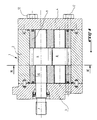
- Figure 1 is an axial sectional view of a hydraulic pump standard gear.
- Figure 2 is a sectional view along the line II-II of Figure 1, more large scale.
- the improved hydraulic gear pump according to the invention has the standard structure known per se as shown in Figures 1 and 2.
- These pumps essentially comprise a housing or casing 1 formed by a body central 2 and front and rear bodies 3 and 4 respectively which define a substantially cylindrical internal space in which two are mounted pinions meshing with each other, namely a driving pinion 6 driven in rotation by a drive shaft 7 and a driven pinion 8.
- the pinions are carried by front and rear bearings indicated at 10 and 11 respectively.
- the drawing further shows at 12 the assembly tie rods of the casing.
- the latter has a suction path 13 of a hydraulic fluid and a discharge path 14 of pressurized fluid.
- the particularity of the present invention resides in the fact that at least one of the pinions 6, 8, namely in particular the driven pinion 8, is produced in a material having in addition appropriate mechanical properties, namely a good resistance to wear and friction, damping properties vibrations induced in the pinion.
- a particularly suitable material is formed from polymers or copolymers advantageously modified by carbon loads. But any other material that has both properties above can be used.
- the material of the led gear could be semi-crystalline aromatic linear polymer marketed under the name PEEK.
- a gear in polymer material, in accordance with the present invention can be manufactured by injection into a mold, which makes it possible to manufacture the pinion a low cost price.
- the use of the polymer material in reducing the noise level extends the possible speed range of the pump.
- the pump, rotating faster has a smaller displacement and is therefore less bulky, on the one hand, and at a price on the other hand, due to the gain in material. In this advantage adds a lighter weight.
Landscapes
- Engineering & Computer Science (AREA)
- Mechanical Engineering (AREA)
- General Engineering & Computer Science (AREA)
- Details And Applications Of Rotary Liquid Pumps (AREA)
- Rotary Pumps (AREA)
Abstract
Description
L'invention concerne une pompe hydraulique à engrenage du type comprenant un pignon menant et un pignon mené engrènant l'un l'autre, dans un carter comportant un canal d'aspiration et un canal de refoulement d'un fluide hydraulique.The invention relates to a hydraulic gear pump of the type comprising a driving pinion and a driven pinion meshing with each other, in a casing comprising a suction channel and a discharge channel of a hydraulic fluid.
Dans les pompes à engrenage de ce type, qui sont connues, les deux pignons sont réalisés en acier et présentent l'inconvénient majeur de produire des émissions sonores importantes qui augmentent avec la vitesse de rotation des pignons. Dans la mesure où un niveau maximal de bruit admissible est fixé par des normes, le champ de l'utilisation des pompes hydrauliques à engrenage est limité.In gear pumps of this type, which are known, the two pinions are made of steel and have the major drawback of producing significant noise emissions which increase with the speed of rotation of gables. As long as a maximum permissible noise level is fixed by standards, the field of use of hydraulic pumps gear is limited.
La présente invention a pour but de réduire le niveau de bruit des pompes hydrauliques à engrenage du type indiqué plus haut.The object of the present invention is to reduce the noise level of the pumps. gear hydraulics of the type indicated above.
Pour atteindre ce but, la pompe hydraulique à engrenage selon l'invention est caractérisée en ce qu'au moins un des pignons est réalisé en un matériau ayant, en plus des propriétés de résistance mécanique, des propriétés d'amortissement de vibrations.To achieve this goal, the hydraulic gear pump according to the invention is characterized in that at least one of the pinions is made of a material having, in addition to mechanical strength properties, properties vibration damping.
Selon une caractéristique selon l'invention, le matériau constitutif dudit pignon possède un coefficient de frottement relativement faible.According to a characteristic according to the invention, the material constituting said pinion has a relatively low coefficient of friction.
Selon encore une autre caractéristique de l'invention, au moins le pignon mené est réalisé en le matériau à faible coefficient de frottement ayant des propriétés d'amortissement de vibrations.According to yet another characteristic of the invention, at least the pinion led is made of low friction material having vibration damping properties.
Selon encore une autre caractéristique de l'invention, le matériau constitutif dudit pignon est un matériau polymère. According to yet another characteristic of the invention, the constituent material said pinion is a polymeric material.
Selon encore une autre caractéristique de l'invention, le matériau polymère est un polymère linéaire aromatique semi-cristalin tel que le matériau commercialisé sous le nom de PEEK.According to yet another characteristic of the invention, the polymer material is a semi-crystalline aromatic linear polymer such as the material marketed under the name of PEEK.
L'invention sera mieux comprise et d'autres buts, caractéristiques, détails et avantages de celle-ci apparaítront plus clairement dans la description explicative qui va suivre faite en référence aux dessins schématiques annexés donnés uniquement à titre d'exemples illustrant un mode de réalisation de l'invention et sur lesquels.The invention will be better understood and other aims, characteristics, details and advantages thereof will appear more clearly in the description explanatory which will follow made with reference to the attached schematic drawings given only as examples illustrating an embodiment of the invention and on which.
La figure 1 est une vue en coupe axiale d'une pompe hydraulique à engrenage standard.Figure 1 is an axial sectional view of a hydraulic pump standard gear.
La figure 2 est une vue en coupe, selon la ligne II-II de la figure 1, à plus grande échelle.Figure 2 is a sectional view along the line II-II of Figure 1, more large scale.
La pompe hydraulique à engrenage améliorée selon l'invention présente la
structure standard connue en soi telle que montrée sur les figures 1 et 2. Ces
pompes comportent essentiellement un boítier ou carter 1 formé par un corps
central 2 et des corps avant et arrière respectivement 3 et 4 qui délimitent un
espace interne sensiblement cylindrique dans lequel sont montés deux
pignons engrenant l'un l'autre, à savoir un pignon menant 6 entraíné en
rotation par un arbre moteur 7 et un pignon mené 8. Les pignons sont portés
par des paliers avant et arrière indiqués respectivement en 10 et en 11. Le
dessin montre en outre en 12 des tirants d'assemblage du carter.The improved hydraulic gear pump according to the invention has the
standard structure known per se as shown in Figures 1 and 2. These
pumps essentially comprise a housing or
Comme on le voit sur la figure 2, ce dernier comporte une voie 13 d'aspiration
d'un fluide hydraulique et une voie de refoulement 14 de fluide sous pression.As seen in Figure 2, the latter has a suction path 13
of a hydraulic fluid and a
Dans les pompes de ce type, les émissions sonores ont deux sources, à savoir elles proviennent de l'engrenage proprement dit, mais aussi du couplage du fluide et de la structure. Concernant le bruit d'engrènement, pendant l'engrènement des pignons qui sont à denture droite à développante de cercle, il se produit inévitablement des glissements relatifs entre les deux flans de dents en contact. Ces glissements engendrent des frottements et donc du bruit. Lorsque les deux pignons sont en acier, le bruit issu du frottement est assez important, notamment en raison de leur coefficient de frottement élevé.In pumps of this type, noise emissions have two sources, know they come from the gear itself, but also from the coupling of the fluid and the structure. Regarding meshing noise, during the meshing of the pinions which are straight to involute of circle, there is inevitably relative sliding between the two flans of teeth in contact. These slippages cause friction and so noise. When the two pinions are made of steel, the noise from the friction is quite significant, in particular because of their coefficient of high friction.
Concernant le couplage entre le fluide et la structure, on a constaté dans le
cadre de l'invention, qu'au cours du processus d'engrènement un volume
d'huile indiqué en 16 se retrouve emprisonné entre les dents et les deux
lumières d'échappement pratiquées sur les paliers de la pompe, à l'aspiration
et au refoulement, désignés respectivement par les références 17 et 18. Ce
volume de fluide hydraulique est comprimé puis détendu lorsque les dents
s'ouvrent à l'aspiration. Ce cycle de compression-détente induit une excitation
périodique sur les dents des pignons, qui se traduit par des vibrations de
l'ensemble formé par les pignons, les paliers et le corps de la pompe. Les
vibrations sont ensuite rayonnées dans le milieu ambiant et créent le bruit.Regarding the coupling between the fluid and the structure, we found in
framework of the invention, that during the meshing process a volume
of oil indicated in 16 is trapped between the teeth and the two
exhaust lights on the pump bearings, on suction
and discharge, designated by the
La particularité de la présente invention réside dans le fait qu'au moins un des
pignons 6, 8, à savoir notamment le pignon mené 8, est réalisé en un
matériau ayant en plus des propriétés mécaniques appropriées, à savoir une
bonne résistance à l'usure et au frottement, des propriétés d'amortissement
des vibrations induites dans le pignon. Un matériau particulièrement approprié
est formé des polymères ou copolymères avantageusement modifiés par des
charges de carbone. Mais tout autre matériau qui possède les deux propriétés
susmentionnées peut être utilisé. A titre d'exemple, le matériau constitutif du
pignon mené pourrait être le polymère linéaire aromatique semi-cristallin
commercialisé sous le nom PEEK. The particularity of the present invention resides in the fact that at least one of the
Le remplacement d'au moins un des pignons en acier par un pignon réalisé en ledit matériau mécaniquement résistant et susceptible d'amortir des vibrations permet d'abaisser le coefficient de frottement donc de réduire le frottement et le bruit qui en résulte. D'autre part, en raison de sa propriété d'amortissement structurale très supérieure à celui de l'acier, une grande partie de l'énergie vibratoire est absorbée et dissipée sous forme de chaleur dans le matériau. Cette chaleur sera dégagée par le fluide hydraulique traversant la pompe.The replacement of at least one of the steel pinions by a pinion made in said mechanically resistant material capable of absorbing vibrations allows to lower the coefficient of friction therefore to reduce friction and the resulting noise. On the other hand, due to its damping property structural much higher than that of steel, a large part of the energy vibratory is absorbed and dissipated as heat in the material. This heat will be released by the hydraulic fluid passing through the pump.
Un pignon en matériau polymère, conforme à la présente invention, peut être fabriqué par injection dans un moule, ce qui permet de fabriquer le pignon à un faible prix de revient.A gear in polymer material, in accordance with the present invention, can be manufactured by injection into a mold, which makes it possible to manufacture the pinion a low cost price.
Etant donné que le niveau de bruit rayonné par la pompe augmente de façon quasi-linéaire avec la vitesse de rotation, l'utilisation du matériau polymère en réduisant le niveau sonore étend la plage de vitesse possible de la pompe. Ainsi, au même débit d'utilisation, la pompe en tournant plus vite a une cylindrée plus petite et est ainsi moins encombrante, d'une part, et d'un prix de revient plus faible, d'autre part, en raison du gain de matière. A cet avantage s'ajoute un poids plus faible.As the noise level radiated by the pump increases so quasi-linear with the speed of rotation, the use of the polymer material in reducing the noise level extends the possible speed range of the pump. Thus, at the same operating rate, the pump, rotating faster, has a smaller displacement and is therefore less bulky, on the one hand, and at a price on the other hand, due to the gain in material. In this advantage adds a lighter weight.
A titre d'exemple, lorsque l'on compare une pompe hydraulique à engrenage selon l'invention, d'une cylindrée de 1 cm3/tour, tournant à une vitesse de rotation de 3000 tours/min. et dont le pignon mené est en PEEK, à une pompe standard, c'est-à-dire avec des pignons en acier, en mesurant le bruit global en chambre sourde avec un sonomètre placé à 50 cm de la pompe, on constate que le niveau de bruit de la pompe standard se situe autour de 51 dBA, alors que le niveau de bruit de la pompe selon l'invention est de seulement 48 dBA. Cette réduction de 3 dBA obtenue grâce à l'invention correspond à u niveau de bruit divisé par 2, c'est-à-dire représente une réduction considérable du bruit.By way of example, when a hydraulic gear pump according to the invention is compared, with a displacement of 1 cm 3 / revolution, rotating at a rotation speed of 3000 revolutions / min. and whose driven pinion is in PEEK, with a standard pump, that is to say with steel pinions, by measuring the overall noise in an anechoic chamber with a sound level meter placed 50 cm from the pump, we see that the noise level of the standard pump is around 51 dBA, while the noise level of the pump according to the invention is only 48 dBA. This reduction of 3 dBA obtained thanks to the invention corresponds to a noise level divided by 2, that is to say represents a considerable reduction in noise.
Claims (6)
Applications Claiming Priority (2)
| Application Number | Priority Date | Filing Date | Title |
|---|---|---|---|
| FR9906801A FR2794188B1 (en) | 1999-05-28 | 1999-05-28 | GEAR HYDRAULIC PUMP |
| FR9906801 | 1999-05-28 |
Publications (2)
| Publication Number | Publication Date |
|---|---|
| EP1055819A1 true EP1055819A1 (en) | 2000-11-29 |
| EP1055819B1 EP1055819B1 (en) | 2007-10-24 |
Family
ID=9546148
Family Applications (1)
| Application Number | Title | Priority Date | Filing Date |
|---|---|---|---|
| EP20000401476 Expired - Lifetime EP1055819B1 (en) | 1999-05-28 | 2000-05-25 | Hydraulic gear pump |
Country Status (3)
| Country | Link |
|---|---|
| EP (1) | EP1055819B1 (en) |
| DE (1) | DE60036833T2 (en) |
| FR (1) | FR2794188B1 (en) |
Cited By (2)
| Publication number | Priority date | Publication date | Assignee | Title |
|---|---|---|---|---|
| WO2007028429A1 (en) * | 2005-09-02 | 2007-03-15 | Fresenius Medical Care Deutschland Gmbh | Gearwheel pump |
| WO2019211540A1 (en) | 2018-05-04 | 2019-11-07 | Exoes | Gear pump for circulating a fluid |
Citations (7)
| Publication number | Priority date | Publication date | Assignee | Title |
|---|---|---|---|---|
| JPS57151087A (en) * | 1981-03-12 | 1982-09-18 | Matsushita Electric Ind Co Ltd | Gear pump |
| US4583924A (en) * | 1983-11-10 | 1986-04-22 | Fresenius Ag | Gear pump, especially for medical purposes |
| US5163824A (en) * | 1990-04-23 | 1992-11-17 | Transcience Associates Inc. | Rubber-geared pump with shaftless gear |
| JPH08247246A (en) * | 1995-01-11 | 1996-09-24 | Mitsubishi Heavy Ind Ltd | Lubricating device of rack pinion for carrier |
| JPH1028930A (en) * | 1996-07-15 | 1998-02-03 | Nkk Corp | Resin-coated metallic body |
| JPH1077974A (en) * | 1996-09-03 | 1998-03-24 | Heishin Sobi Kk | Single-shaft eccentric screw pump |
| US5865239A (en) * | 1997-02-05 | 1999-02-02 | Micropump, Inc. | Method for making herringbone gears |
-
1999
- 1999-05-28 FR FR9906801A patent/FR2794188B1/en not_active Expired - Lifetime
-
2000
- 2000-05-25 EP EP20000401476 patent/EP1055819B1/en not_active Expired - Lifetime
- 2000-05-25 DE DE2000636833 patent/DE60036833T2/en not_active Expired - Lifetime
Patent Citations (7)
| Publication number | Priority date | Publication date | Assignee | Title |
|---|---|---|---|---|
| JPS57151087A (en) * | 1981-03-12 | 1982-09-18 | Matsushita Electric Ind Co Ltd | Gear pump |
| US4583924A (en) * | 1983-11-10 | 1986-04-22 | Fresenius Ag | Gear pump, especially for medical purposes |
| US5163824A (en) * | 1990-04-23 | 1992-11-17 | Transcience Associates Inc. | Rubber-geared pump with shaftless gear |
| JPH08247246A (en) * | 1995-01-11 | 1996-09-24 | Mitsubishi Heavy Ind Ltd | Lubricating device of rack pinion for carrier |
| JPH1028930A (en) * | 1996-07-15 | 1998-02-03 | Nkk Corp | Resin-coated metallic body |
| JPH1077974A (en) * | 1996-09-03 | 1998-03-24 | Heishin Sobi Kk | Single-shaft eccentric screw pump |
| US5865239A (en) * | 1997-02-05 | 1999-02-02 | Micropump, Inc. | Method for making herringbone gears |
Non-Patent Citations (4)
| Title |
|---|
| PATENT ABSTRACTS OF JAPAN vol. 006, no. 256 (M - 179) 15 December 1982 (1982-12-15) * |
| PATENT ABSTRACTS OF JAPAN vol. 1997, no. 01 31 January 1997 (1997-01-31) * |
| PATENT ABSTRACTS OF JAPAN vol. 1998, no. 06 30 April 1998 (1998-04-30) * |
| PATENT ABSTRACTS OF JAPAN vol. 1998, no. 08 30 June 1998 (1998-06-30) * |
Cited By (3)
| Publication number | Priority date | Publication date | Assignee | Title |
|---|---|---|---|---|
| WO2007028429A1 (en) * | 2005-09-02 | 2007-03-15 | Fresenius Medical Care Deutschland Gmbh | Gearwheel pump |
| WO2019211540A1 (en) | 2018-05-04 | 2019-11-07 | Exoes | Gear pump for circulating a fluid |
| FR3080892A1 (en) * | 2018-05-04 | 2019-11-08 | Exoes | GEAR PUMP FOR CIRCULATING A FLUID |
Also Published As
| Publication number | Publication date |
|---|---|
| DE60036833D1 (en) | 2007-12-06 |
| FR2794188A1 (en) | 2000-12-01 |
| EP1055819B1 (en) | 2007-10-24 |
| FR2794188B1 (en) | 2001-08-10 |
| DE60036833T2 (en) | 2008-07-31 |
Similar Documents
| Publication | Publication Date | Title |
|---|---|---|
| EP1759125B1 (en) | Device for guiding a shaft in an oscillating movement | |
| FR2473127A1 (en) | PUMP DEVICE FOR UTILITY VEHICLES, HAVING TWO PUMPS MADE IN A SINGLE HOUSING | |
| FR2677414A1 (en) | Motor equipped with a worm-type reduction gear mechanism | |
| FR2495713A1 (en) | DEVICE FOR ABSORBING TORSION VIBRATIONS | |
| FR2881189A1 (en) | VACUUM PUMP CIRCULAR CIRCULAR TRANSLATION CYCLE WITH SEVERAL TREES | |
| EP2281107B1 (en) | Engine with a variable volume chamber | |
| FR3042249A3 (en) | TRANSMISSION BETWEEN A COMBUSTION ENGINE AND A COMPRESSOR-COMPRESSOR ELEMENT, AND COMPRESSION INSTALLATION HAVING A TRANSMISSION OF THIS TYPE | |
| EP1055819B1 (en) | Hydraulic gear pump | |
| FR2808465A1 (en) | COOLING SYSTEM FOR A HAND-HELD WORKING TOOL | |
| FR2657122A1 (en) | FUEL PUMP FOR INJECTION SYSTEMS OF EXPLOSION ENGINES. | |
| FR2830905A1 (en) | Vacuum pump, for braking force intensification systems in motor vehicles comprises a rotor which is made of a plastic material hardenable by heat | |
| WO1981003200A1 (en) | Power amplifier for thermal motors or the like | |
| FR3055119A1 (en) | ICE WIPER TRAINING | |
| CA3078596A1 (en) | Spherical device provided with convex splines for forming a ball-and-socket joint having a finger, and wobble pump provided with such a device | |
| FR2837773A1 (en) | VEHICLE STEERING APPARATUS | |
| FR2663012A1 (en) | Shaker with non-metallic gears (gearing) | |
| BE1005111A3 (en) | Device for preparing the form of charges of a product in bulk. | |
| EP0052387A1 (en) | Motor with at least one linear-translationpiston and wobble plate | |
| FR3026793B1 (en) | HYDRAULIC MACHINE COMPRISING EXTENDED FASTENING BOSSAGES TO REDUCE NOISE | |
| EP1608893B1 (en) | Pulley, detection device comprising one such pulley, and internal combustion engine provided with one such device | |
| FR3075277A1 (en) | SPHERES SERIES HYDRAULIC PUMP | |
| FR2995016A1 (en) | EXHAUST GAS TURBOCHARGER | |
| FR2917142A1 (en) | PIECE FORMING OLDHAM NUTS. | |
| FR2547551A1 (en) | Speed reducer for aviation engine | |
| FR2772827A1 (en) | Driving device with hydraulic brake for a pump in a deep shaft |
Legal Events
| Date | Code | Title | Description |
|---|---|---|---|
| PUAI | Public reference made under article 153(3) epc to a published international application that has entered the european phase |
Free format text: ORIGINAL CODE: 0009012 |
|
| AK | Designated contracting states |
Kind code of ref document: A1 Designated state(s): DE GB IT SE |
|
| AX | Request for extension of the european patent |
Free format text: AL;LT;LV;MK;RO;SI |
|
| 17P | Request for examination filed |
Effective date: 20010523 |
|
| AKX | Designation fees paid |
Free format text: DE GB IT SE |
|
| 17Q | First examination report despatched |
Effective date: 20050307 |
|
| GRAP | Despatch of communication of intention to grant a patent |
Free format text: ORIGINAL CODE: EPIDOSNIGR1 |
|
| GRAS | Grant fee paid |
Free format text: ORIGINAL CODE: EPIDOSNIGR3 |
|
| GRAA | (expected) grant |
Free format text: ORIGINAL CODE: 0009210 |
|
| AK | Designated contracting states |
Kind code of ref document: B1 Designated state(s): DE GB IT SE |
|
| REG | Reference to a national code |
Ref country code: GB Ref legal event code: FG4D Free format text: NOT ENGLISH |
|
| REF | Corresponds to: |
Ref document number: 60036833 Country of ref document: DE Date of ref document: 20071206 Kind code of ref document: P |
|
| REG | Reference to a national code |
Ref country code: SE Ref legal event code: TRGR |
|
| GBT | Gb: translation of ep patent filed (gb section 77(6)(a)/1977) |
Effective date: 20080131 |
|
| PLBE | No opposition filed within time limit |
Free format text: ORIGINAL CODE: 0009261 |
|
| STAA | Information on the status of an ep patent application or granted ep patent |
Free format text: STATUS: NO OPPOSITION FILED WITHIN TIME LIMIT |
|
| 26N | No opposition filed |
Effective date: 20080725 |
|
| PGFP | Annual fee paid to national office [announced via postgrant information from national office to epo] |
Ref country code: IT Payment date: 20190529 Year of fee payment: 20 |
|
| PGFP | Annual fee paid to national office [announced via postgrant information from national office to epo] |
Ref country code: SE Payment date: 20190527 Year of fee payment: 20 |
|
| PGFP | Annual fee paid to national office [announced via postgrant information from national office to epo] |
Ref country code: DE Payment date: 20190731 Year of fee payment: 20 Ref country code: GB Payment date: 20190529 Year of fee payment: 20 |
|
| REG | Reference to a national code |
Ref country code: DE Ref legal event code: R071 Ref document number: 60036833 Country of ref document: DE |
|
| REG | Reference to a national code |
Ref country code: GB Ref legal event code: PE20 Expiry date: 20200524 |
|
| REG | Reference to a national code |
Ref country code: SE Ref legal event code: EUG |
|
| PG25 | Lapsed in a contracting state [announced via postgrant information from national office to epo] |
Ref country code: GB Free format text: LAPSE BECAUSE OF EXPIRATION OF PROTECTION Effective date: 20200524 |