EP1054338A1 - Patient monitor with continuous status display - Google Patents
Patient monitor with continuous status display Download PDFInfo
- Publication number
- EP1054338A1 EP1054338A1 EP00102810A EP00102810A EP1054338A1 EP 1054338 A1 EP1054338 A1 EP 1054338A1 EP 00102810 A EP00102810 A EP 00102810A EP 00102810 A EP00102810 A EP 00102810A EP 1054338 A1 EP1054338 A1 EP 1054338A1
- Authority
- EP
- European Patent Office
- Prior art keywords
- patient
- local
- display
- monitors
- patient monitor
- Prior art date
- Legal status (The legal status is an assumption and is not a legal conclusion. Google has not performed a legal analysis and makes no representation as to the accuracy of the status listed.)
- Ceased
Links
Images

Classifications
-
- G—PHYSICS
- G16—INFORMATION AND COMMUNICATION TECHNOLOGY [ICT] SPECIALLY ADAPTED FOR SPECIFIC APPLICATION FIELDS
- G16H—HEALTHCARE INFORMATICS, i.e. INFORMATION AND COMMUNICATION TECHNOLOGY [ICT] SPECIALLY ADAPTED FOR THE HANDLING OR PROCESSING OF MEDICAL OR HEALTHCARE DATA
- G16H40/00—ICT specially adapted for the management or administration of healthcare resources or facilities; ICT specially adapted for the management or operation of medical equipment or devices
- G16H40/60—ICT specially adapted for the management or administration of healthcare resources or facilities; ICT specially adapted for the management or operation of medical equipment or devices for the operation of medical equipment or devices
- G16H40/67—ICT specially adapted for the management or administration of healthcare resources or facilities; ICT specially adapted for the management or operation of medical equipment or devices for the operation of medical equipment or devices for remote operation
Definitions
- the present invention relates to patient monitors for monitoring the physiological condition of a patient, in particular networked patient monitors.
- the central station 30 is normally located remote from the bedside monitors BEDi.
- the central station 30 typically allows displaying status and real time data of all or a subset of the connected bedside monitors BEDi.
- the central station 30 further generally allows to view one individual bedside monitor BEDi in greater detail provided in a specific window, as e.g. by the Patient Window of the Agilent Information Center of Agilent Technologies.
- the Remote Link product of Agilent Technologies allows remotely viewing information from different bedsides similar to a central station e.g. in a doctors office. It does not trigger any alarms, but displays patient status in a comprehensive overview (color coded boxes), and similar to a central station allows to overview more data of a single bed in a window.
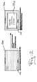
- existing networked bedside monitors BEDi usually provide a display 100 showing data, such as alarms and/or measured data, from the local bedside monitor BEDi.
- Data of another (remote) bedside monitor BEDj can be selected by means of buttons 110 (e.g. soft or hard keys) and displayed in a pop-up window 120 generally overlapping the data display of the local bedside monitor BEDi.
- buttons 110 e.g. soft or hard keys
- the pop-up window 120 and an alarm tone can appear when another bedside monitor BEDj goes into an alarming state.
- a manual navigation scheme generally allows viewing other bedside monitors BEDi independent of an alarming situation.
- the invention provides a way of helping clinical staff to assess the status of a plurality of patients at one glance by permanently presenting the status of a plurality of bedside monitors on a reserved area of each bedside monitor.
- This status information is provided continuously and independently of an alarming situation.
- the reserved area for this status information is displayed in a side area of the monitor display and/or separated from other data to be displayed (such as data from a local or remote bedside monitor).
- the invention allows providing a comprehensive overview over the related bedside monitors without disturbing local operations or data monitoring, e.g. by pop-up windows covering or overlapping the data display.
- related monitors shall represent a plurality of monitors connected with each other, e.g. by means of a data network, thus allowing a data communication between the monitors. Accordingly, the term “monitor as used herein shall represent any kind of patient monitor applicable for monitoring physiological information of a patient.
- the invention overcomes a disadvantage of conventional bedside monitors, which normally only render available information about other bedside monitors in case of an alarm or after a user interaction, however always only the information of one bedside monitor is displayed at the same time. Furthermore, the invention preferably allows providing such status information generally without overlapping other data display.
- a patient monitor might resemble a conventional computer to a certain degree, the patient monitor still represents a measuring device.
- the main purpose of a measuring device is to measure data and make the measured data available e.g. by displaying the measured data. Therefore, it is important for measuring devices that essential information will be made available and is not accidentally suppressed e.g. by being overlapped. This is in particular of relevance for patient monitoring where a patient's physiological signals are monitored and where a not-showing of vital information can cause serious harm to the patient.
- a continuous display of status information also of other related bedside monitors, however without interfering with the selected display therefore represents a significant improvement for patient monitoring applications.
- an area of a screen of a patient monitor is allocated for displaying the status information in an overview area.
- the overview area remains preferably allocated permanently or at least as long as defined by the respective application or by a user
- the remaining area of the screen can be used for displaying other kind of information, e.g. to show data of the local patient connected to the respective patient monitor, or to view (e.g. in greater detail) information from other patient monitors, but also for increasing the overview area.
- the location and the size of the overview area depend on the specific screen configurations. It is also clear that the overview area needs not necessarily be a static area fixed to a certain location, but is also moveable along the screen. However, the overview area is preferably spatially separated from the other display areas and will preferably not or only temporarily overlap or be overlapped therewith.
- the overview area allows to concurrently display the status of other patient monitors connected to that patient monitor e.g. via a network.
- This status of other patient monitors is preferably displayed using symbols, codes or pictograms.
- this status information can also be provided with alphanumerical text fields, e.g. for indicating a specific alarming state or the other patient's name.
- the size of the overview area can be further increased in order to display more or more detailed information about one or more of the other related patient monitors, and/or decreased to reduce the information content displayed.
- the overview area can only be reduced in size until a predefined minimum, which still enables to overview the other patient monitors.
- the overview area provides entry points for operations to get more information from a related patient monitor and/or to involve a remote operation (e.g. a button to silence an alarm or to show a window to change alarm limits).
- a remote operation e.g. a button to silence an alarm or to show a window to change alarm limits.
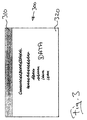
- Figure 3 shows a screen 300 of a (local) patient monitor according to a preferred embodiment of the invention.
- An area of the screen 300 is allocated as an overview area 310 for continuously displaying status information of other (remote) patient monitors connected with the local patient monitor e.g. via a data network.
- the remaining space of the screen 300 or parts thereof can be used as a data display 320, e.g. to show data (such as alarms, numeric signs, graphical data curves (waves), or status information) of a local or a remote patient.
- the data display 320 can represent the display 100 of Fig. 2.
- the location and the size of the overview area 310 depend on the specific configuration of the screen 300 and can be defined by a software designer or a sophisticated user.
- the overview area 310 is completely separated from the data display 320, so that neither the data display 320 itself nor any dialog window will overlay and cover the overview area 310.
- the normal mode can be left temporarily, e.g. on user request, and the overview area 310 and the data display 320 might be overlapped shortly.
- the overview area 310 is used to display the status of other related patient monitors connected with the local patient monitor (e.g. as shown in Fig. 1).
- the number of other patient monitors of which the status can be displayed in the overview area 310 can be limited to a specific set of patient monitors.
- Such limitations can preferably be provided according to personal criteria, e.g. the patient monitors of a care group (which is usually taken care by one nurse or a specific group of nurses), or according to locality criteria, e.g. the patient monitors of a specific room in a hospital.
- This status information is preferably displayed by means of symbols, pictograms, codings and/or alphanumeric signs.
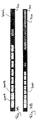
- Figure 4A shows an example for the overview area 310.
- the status of up to 12 related patient monitors could be displayed in the overview area 310.
- a specific status field 400A, 400B, ..., 400L is reserved.
- the spatial arrangement of the status fields 400 preferably corresponds with the actual physical arrangement of the respective patient monitors and/or beds, e.g. in a way that the order of the status fields 400 represents the physical or spatial order of the corresponding beds in that (care) group.
- the assignment of the status fields 400 to the respective beds will preferably be maintained and will only change when required.
- the status fields can be grouped, e.g. in groups of four.
- Figure 4B shows another example of the overview area 310 with status fields 400 and one or more alarm text fields 410 (only one text field is shown in Fig. 4B).
- active alarm texts and/or the respective patient name from other related patient monitors could be displayed in the text field(s) 410. If more alarms from different beds are active at the same time, the related alarm texts are preferably rotated in the alarm text field(s), and the related status field 400 is highlighted respectively.
- a reservation of one status field for the local patient monitor irrespectively of the current display in the data display 320 might also be useful for improve an intuitive understandability of the overview area 310, e.g. when the arrangement of the status fields corresponds to the spatial arrangement of the related (local and remote) patient monitors.
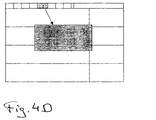
- Figure 40 shows another example of the overview area 310. If, for example in the embodiment of Figures 4A and 4B, the permanently visible overview area 310 of the remote patient monitors is enlarged, the status of an individual patient monitor can be extended to display more or more detailed information.
- the upper left status field 400A shows a bed label, alarms, a subset of parameters and one wave for the respective related patient monitor.
- the overview area 310 can also be used as entry point for operations to get more or more detailed information about one or more of the related patient monitors, or to invoke a remote operation such as to silence an alarm or to change alarm limits.
- a pop-up window 450 will be opened by selecting (e.g. clicking on) the status fields 400E represented by a numeric sign "5".
- the pop-up window 450 represents data of the (remote) patient monitor assigned by the numeric sign "5" and can be further processed as known in the art.
Abstract
Description
- The present invention relates to patient monitors for monitoring the physiological condition of a patient, in particular networked patient monitors.
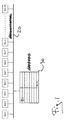
- One of the most important tasks of bedside patient monitoring is the generation of alarms. If, as shown in a typical example in Figure 1, a plurality of bedside monitors BEDi (with i = 1 to 16 in Fig. 1) are connected via a
network 20, an alarm status of each bedside monitor BEDi can be distributed to acentral station 30 or to any other of the bedside monitors BEDi. Thecentral station 30 is normally located remote from the bedside monitors BEDi. - The
central station 30 typically allows displaying status and real time data of all or a subset of the connected bedside monitors BEDi. Thecentral station 30 further generally allows to view one individual bedside monitor BEDi in greater detail provided in a specific window, as e.g. by the Patient Window of the Agilent Information Center of Agilent Technologies. The Remote Link product of Agilent Technologies allows remotely viewing information from different bedsides similar to a central station e.g. in a doctors office. It does not trigger any alarms, but displays patient status in a comprehensive overview (color coded boxes), and similar to a central station allows to overview more data of a single bed in a window. - As depicted in Figure 2, existing networked bedside monitors BEDi usually provide a
display 100 showing data, such as alarms and/or measured data, from the local bedside monitor BEDi. Data of another (remote) bedside monitor BEDj (with j ≠ i) can be selected by means of buttons 110 (e.g. soft or hard keys) and displayed in a pop-upwindow 120 generally overlapping the data display of the local bedside monitor BEDi. Alternatively, the pop-upwindow 120 and an alarm tone can appear when another bedside monitor BEDj goes into an alarming state. A manual navigation scheme generally allows viewing other bedside monitors BEDi independent of an alarming situation. - Although the existing bedside monitors already provide precious tools for monitoring a patient's physiological condition, it is still required to further improve patient monitoring, in particular in networked applications.
- The object is solved by the independent claims. Preferred embodiments are shown by the dependent claims.
- The invention provides a way of helping clinical staff to assess the status of a plurality of patients at one glance by permanently presenting the status of a plurality of bedside monitors on a reserved area of each bedside monitor. This status information is provided continuously and independently of an alarming situation. Preferably, the reserved area for this status information is displayed in a side area of the monitor display and/or separated from other data to be displayed (such as data from a local or remote bedside monitor). Thus, the invention allows providing a comprehensive overview over the related bedside monitors without disturbing local operations or data monitoring, e.g. by pop-up windows covering or overlapping the data display.
- The term "related monitors" as used herein shall represent a plurality of monitors connected with each other, e.g. by means of a data network, thus allowing a data communication between the monitors. Accordingly, the term "monitor as used herein shall represent any kind of patient monitor applicable for monitoring physiological information of a patient.
- By displaying a continuous status information for related bedside monitors, the invention overcomes a disadvantage of conventional bedside monitors, which normally only render available information about other bedside monitors in case of an alarm or after a user interaction, however always only the information of one bedside monitor is displayed at the same time. Furthermore, the invention preferably allows providing such status information generally without overlapping other data display.
- For fully appreciating the contribution of the invention, it has to be understood that although a patient monitor might resemble a conventional computer to a certain degree, the patient monitor still represents a measuring device. The main purpose of a measuring device, however, is to measure data and make the measured data available e.g. by displaying the measured data. Therefore, it is important for measuring devices that essential information will be made available and is not accidentally suppressed e.g. by being overlapped. This is in particular of relevance for patient monitoring where a patient's physiological signals are monitored and where a not-showing of vital information can cause serious harm to the patient. A continuous display of status information also of other related bedside monitors, however without interfering with the selected display therefore represents a significant improvement for patient monitoring applications.
- In a preferred embodiment of the invention, an area of a screen of a patient monitor is allocated for displaying the status information in an overview area. The overview area remains preferably allocated permanently or at least as long as defined by the respective application or by a user The remaining area of the screen can be used for displaying other kind of information, e.g. to show data of the local patient connected to the respective patient monitor, or to view (e.g. in greater detail) information from other patient monitors, but also for increasing the overview area.
- The location and the size of the overview area depend on the specific screen configurations. It is also clear that the overview area needs not necessarily be a static area fixed to a certain location, but is also moveable along the screen. However, the overview area is preferably spatially separated from the other display areas and will preferably not or only temporarily overlap or be overlapped therewith.
- The overview area allows to concurrently display the status of other patient monitors connected to that patient monitor e.g. via a network. This status of other patient monitors is preferably displayed using symbols, codes or pictograms. Alternatively or in addition thereto, this status information can also be provided with alphanumerical text fields, e.g. for indicating a specific alarming state or the other patient's name.
- In a preferred embodiment, the size of the overview area can be further increased in order to display more or more detailed information about one or more of the other related patient monitors, and/or decreased to reduce the information content displayed. Preferably, the overview area can only be reduced in size until a predefined minimum, which still enables to overview the other patient monitors.
- In another preferred embodiment, the overview area provides entry points for operations to get more information from a related patient monitor and/or to involve a remote operation (e.g. a button to silence an alarm or to show a window to change alarm limits).
- It is clear that the invention can be partly or entirely embodied by one or more suitable software programs, which can be stored on or otherwise provided by any kind of data carrier, and which might be executed in or by any suitable data processing unit.
- Other objects and many of the attendant advantages of the present invention will be readily appreciated and become better understood by reference to the following detailed description when considering in connection with the accompanied drawings. Features that are substantially or functionally equal or similar will be referred to with the same reference sign(s).
- Fig. 1
- shows a typical example of bedside monitors connected via a
network 20, as known in the art, - Fig. 2
- depicts a display of an existing networked bedside monitor,
- Fig. 3
- shows a screen 300 of a (local) patient monitor according to a preferred embodiment of the invention, and
- Figs. 4A-D
- illustrate examples of
overview areas 310 according to the present invention. - Figure 3 shows a screen 300 of a (local) patient monitor according to a preferred embodiment of the invention. An area of the screen 300 is allocated as an
overview area 310 for continuously displaying status information of other (remote) patient monitors connected with the local patient monitor e.g. via a data network. The remaining space of the screen 300 or parts thereof can be used as adata display 320, e.g. to show data (such as alarms, numeric signs, graphical data curves (waves), or status information) of a local or a remote patient. Thedata display 320 can represent thedisplay 100 of Fig. 2. - The location and the size of the
overview area 310 depend on the specific configuration of the screen 300 and can be defined by a software designer or a sophisticated user. - In a normal mode of a preferred embodiment, the
overview area 310 is completely separated from thedata display 320, so that neither the data display 320 itself nor any dialog window will overlay and cover theoverview area 310. The normal mode can be left temporarily, e.g. on user request, and theoverview area 310 and thedata display 320 might be overlapped shortly. - The
overview area 310 is used to display the status of other related patient monitors connected with the local patient monitor (e.g. as shown in Fig. 1). - Preferably, the number of other patient monitors of which the status can be displayed in the
overview area 310 can be limited to a specific set of patient monitors. Such limitations can preferably be provided according to personal criteria, e.g. the patient monitors of a care group (which is usually taken care by one nurse or a specific group of nurses), or according to locality criteria, e.g. the patient monitors of a specific room in a hospital. This status information is preferably displayed by means of symbols, pictograms, codings and/or alphanumeric signs. - Figure 4A shows an example for the
overview area 310. In that example, the status of up to 12 related patient monitors could be displayed in theoverview area 310. For each related patient monitor, aspecific status field 400A, 400B, ..., 400L is reserved. The spatial arrangement of the status fields 400 preferably corresponds with the actual physical arrangement of the respective patient monitors and/or beds, e.g. in a way that the order of the status fields 400 represents the physical or spatial order of the corresponding beds in that (care) group. The assignment of the status fields 400 to the respective beds will preferably be maintained and will only change when required. For better recognition, the status fields can be grouped, e.g. in groups of four. - In Figure 4A, a specific coding scheme is applied, e.g.:
- • Bed not online or off:
- dark blue background
- • Bed online and no alarm:
- white box with dark blue background
- • Technical alarm:
- "-?-" with light blue (cyan) background
- • Limit alarm:
- "**" (blinking) with yellow background
- • Severe alarm:
- "**" (blinking) with red background
- • Alarms turned off
- red crossed out bell on white background
- • Demo mode:
- "DEMO" with dark blue background
- • Stand-by mode:
- "standby symbol" with dark blue background
- • Local bed:
- white box with black background.
- It is clear that a different coding and/or (graphical) presentation stile can be used accordingly.
- Figure 4B shows another example of the
overview area 310 withstatus fields 400 and one or more alarm text fields 410 (only one text field is shown in Fig. 4B). In addition to the status fields 400, active alarm texts and/or the respective patient name from other related patient monitors could be displayed in the text field(s) 410. If more alarms from different beds are active at the same time, the related alarm texts are preferably rotated in the alarm text field(s), and therelated status field 400 is highlighted respectively. - While the
overview area 310 in the examples of Figs. 4A and 4B only displays status fields 400 of other related (remote) patient monitors, it is clear that onestatus field 400 can also be reserved for the local patient monitor. This is in particular useful when thedata display 320 will be applied for displaying data of a remote patient monitor. In such a case, however, the status fields 400 might also be adapted automatically to the present display at thedata display 320, so that when thedata display 320 displays information of a remote patient monitor (instead of the local patient monitor) the status field of that remote patient monitor will be automatically exchanged against a status field for the local patient monitor. A reservation of one status field for the local patient monitor irrespectively of the current display in the data display 320 might also be useful for improve an intuitive understandability of theoverview area 310, e.g. when the arrangement of the status fields corresponds to the spatial arrangement of the related (local and remote) patient monitors. - Figure 40 shows another example of the
overview area 310. If, for example in the embodiment of Figures 4A and 4B, the permanentlyvisible overview area 310 of the remote patient monitors is enlarged, the status of an individual patient monitor can be extended to display more or more detailed information. In the example of Figure 4C, the upper left status field 400A shows a bed label, alarms, a subset of parameters and one wave for the respective related patient monitor. - In a preferred embodiment as depicted in Fig. 4D, the
overview area 310 can also be used as entry point for operations to get more or more detailed information about one or more of the related patient monitors, or to invoke a remote operation such as to silence an alarm or to change alarm limits. In the example of Fig. 4D, a pop-up window 450 will be opened by selecting (e.g. clicking on) the status fields 400E represented by a numeric sign "5". The pop-up window 450 represents data of the (remote) patient monitor assigned by the numeric sign "5" and can be further processed as known in the art.
Claims (10)
- A local patient monitor (BEDi) for monitoring the physiological condition of a local patient, whereby the local patient monitor is adapted to provide a data-communication with one or more remote patient monitors (BEDj) in a network (20) with or without an additional central data-display component (30), the local patient monitor comprising:a display (300) adapted for displaying information preferably representative of the physiological condition of the local patient,
characterized in that the display (300) comprises an overview area (310) for displaying status information from the one or more remote patient monitors. - The local patient monitor of claim 1, characterized in that the overview area (310) provides the status information continuously and independently of an alarming situation.
- The local patient monitor of claim 1 or 2, characterized in that the overview area (310) is a side area of the display (300) and/or separated from other data to be displayed.
- The local patient monitor of any one of the above claims, characterized in that the overview area (310) is spatially separated from other display areas of the display (300) for displaying other information, whereby the local patient monitor further comprises means for ensuring that the other display areas will not or only temporarily overlap the overview area (310) on user request.
- The local patient monitor of any one of the above claims, characterized in that the overview area (310) remains permanently allocated within the display (300) or at least as long as defined by a respective application or by a user.
- The local patient monitor of any one of the above claims, characterized in that the overview area (310) comprises symbols, codes, pictograms, graphical data curves, and/or alphanumerical text fields for displaying the status information.
- The local patient monitor of any one of the above claims, characterized in that the size of the overview area (310) comprises at least one entry point for operations to get more information from one or more of the remote patient monitors.
- A patient monitoring system comprising:a plurality of patient monitors, each adapted for monitoring the physiological condition of a local patient connected with the respective patient monitor, wherebycharacterized in that the display (300) of at least one of the patient monitors comprises an overview area (310) for displaying status information from one or more of the other patient monitors.the patient monitors are adapted to provide a data-communication with each other, andeach patient monitor comprises a display (300) adapted for displaying information preferably representative of the physiological condition of the local patient,
- A method for monitoring the physiological condition of a local patient with a local patient monitor (BEDi) adapted to provide a data-communication with one or more remote patient monitors (BEDj) in a network (20) with or without an additional central data-display component (30), the method comprising the steps of:displaying information preferably representative of the physiological condition of the local patient, anddisplaying status information from the one or more remote patient monitors.
- A software program, adapted to be stored on or otherwise provided by any kind of data carrier, for executing the steps of the method of claim 9 when run in or by any suitable data processing unit.
Priority Applications (3)
| Application Number | Priority Date | Filing Date | Title |
|---|---|---|---|
| EP00102810A EP1054338A1 (en) | 2000-02-11 | 2000-02-11 | Patient monitor with continuous status display |
| US09/778,189 US6731311B2 (en) | 2000-02-11 | 2001-02-07 | Patient monitor with continuous status display |
| JP2001033753A JP2001245855A (en) | 2000-02-11 | 2001-02-09 | Patient monitoring apparatus displaying patient's condition continuously |
Applications Claiming Priority (1)
| Application Number | Priority Date | Filing Date | Title |
|---|---|---|---|
| EP00102810A EP1054338A1 (en) | 2000-02-11 | 2000-02-11 | Patient monitor with continuous status display |
Publications (1)
| Publication Number | Publication Date |
|---|---|
| EP1054338A1 true EP1054338A1 (en) | 2000-11-22 |
Family
ID=8167824
Family Applications (1)
| Application Number | Title | Priority Date | Filing Date |
|---|---|---|---|
| EP00102810A Ceased EP1054338A1 (en) | 2000-02-11 | 2000-02-11 | Patient monitor with continuous status display |
Country Status (3)
| Country | Link |
|---|---|
| US (1) | US6731311B2 (en) |
| EP (1) | EP1054338A1 (en) |
| JP (1) | JP2001245855A (en) |
Cited By (13)
| Publication number | Priority date | Publication date | Assignee | Title |
|---|---|---|---|---|
| EP1238626A2 (en) * | 2001-03-06 | 2002-09-11 | Nihon Kohden Corporation | Vital sign display |
| GB2460527A (en) * | 2008-06-03 | 2009-12-09 | Gen Electric | Patient monitoring system with health status indicator |
| CN102106757A (en) * | 2009-12-23 | 2011-06-29 | 迈瑞Ds美国有限责任公司 | Systems and methods for remote patient monitoring |
| US8690771B2 (en) | 2005-03-02 | 2014-04-08 | Spacelabs Healthcare, Llc | Trending display of patient wellness |
| US8956292B2 (en) | 2005-03-02 | 2015-02-17 | Spacelabs Healthcare Llc | Trending display of patient wellness |
| US9152765B2 (en) | 2010-03-21 | 2015-10-06 | Spacelabs Healthcare Llc | Multi-display bedside monitoring system |
| US9298889B2 (en) | 2007-03-09 | 2016-03-29 | Spacelabs Healthcare Llc | Health data collection tool |
| US9384652B2 (en) | 2010-11-19 | 2016-07-05 | Spacelabs Healthcare, Llc | System and method for transfer of primary alarm notification on patient monitoring systems |
| US9604020B2 (en) | 2009-10-16 | 2017-03-28 | Spacelabs Healthcare Llc | Integrated, extendable anesthesia system |
| US9797764B2 (en) | 2009-10-16 | 2017-10-24 | Spacelabs Healthcare, Llc | Light enhanced flow tube |
| US10699811B2 (en) | 2011-03-11 | 2020-06-30 | Spacelabs Healthcare L.L.C. | Methods and systems to determine multi-parameter managed alarm hierarchy during patient monitoring |
| US10987026B2 (en) | 2013-05-30 | 2021-04-27 | Spacelabs Healthcare Llc | Capnography module with automatic switching between mainstream and sidestream monitoring |
| CN113348517A (en) * | 2019-01-22 | 2021-09-03 | 日本光电工业株式会社 | Patient monitor and physiological information measuring system |
Families Citing this family (74)
| Publication number | Priority date | Publication date | Assignee | Title |
|---|---|---|---|---|
| US8732573B2 (en) | 2000-05-10 | 2014-05-20 | Teletracking Technologies, Inc. | Visual display of room information |
| US8560580B1 (en) | 1999-05-10 | 2013-10-15 | Teletracking Technologies, Inc. | Visual display of room information |
| AU2001253702A1 (en) * | 2000-04-19 | 2001-10-30 | Broadcom Corporation | Apparatus and method for persistent display interface |
| EP1665479A4 (en) | 2003-08-21 | 2008-01-23 | Hill Rom Services Inc | Plug and receptacle having wired and wireless coupling |
| US20070176790A1 (en) * | 2003-12-19 | 2007-08-02 | Koninklijke Philips Electronics Nv | Patient network with wireless medical apparatuses and allocation thereof to a patient and his network |
| EP1697869A2 (en) * | 2003-12-19 | 2006-09-06 | Philips Intellectual Property & Standards GmbH | Medical device which can be operated with various operating settings, in particular patient monitor |
| US8491492B2 (en) | 2004-02-05 | 2013-07-23 | Earlysense Ltd. | Monitoring a condition of a subject |
| JP4809779B2 (en) | 2004-02-05 | 2011-11-09 | アーリーセンス・リミテッド | Prediction and monitoring technology for clinical onset in respiration |
| US8403865B2 (en) * | 2004-02-05 | 2013-03-26 | Earlysense Ltd. | Prediction and monitoring of clinical episodes |
| US8942779B2 (en) | 2004-02-05 | 2015-01-27 | Early Sense Ltd. | Monitoring a condition of a subject |
| US7319386B2 (en) * | 2004-08-02 | 2008-01-15 | Hill-Rom Services, Inc. | Configurable system for alerting caregivers |
| US7852208B2 (en) | 2004-08-02 | 2010-12-14 | Hill-Rom Services, Inc. | Wireless bed connectivity |
| US20060085398A1 (en) * | 2004-10-19 | 2006-04-20 | Meyers Susan A | System and method for augmenting presentation of patient-related medical information |
| US20060106645A1 (en) * | 2004-11-17 | 2006-05-18 | Adhd Systems, Llc | System and methods for tracking medical encounters |
| US7945452B2 (en) * | 2005-04-11 | 2011-05-17 | Hospira, Inc. | User interface improvements for medical devices |
| US7895527B2 (en) | 2005-07-15 | 2011-02-22 | Siemens Medical Solutions Usa, Inc. | Systems, user interfaces, and methods for processing medical data |
| US9092834B2 (en) * | 2005-12-09 | 2015-07-28 | General Electric Company | System and method for automatically adjusting medical displays |
| US20080214919A1 (en) * | 2006-12-26 | 2008-09-04 | Lifescan, Inc. | System and method for implementation of glycemic control protocols |
| US20080194918A1 (en) * | 2007-02-09 | 2008-08-14 | Kulik Robert S | Vital signs monitor with patient entertainment console |
| US8585607B2 (en) | 2007-05-02 | 2013-11-19 | Earlysense Ltd. | Monitoring, predicting and treating clinical episodes |
| US20090054736A1 (en) * | 2007-08-23 | 2009-02-26 | General Electric Company | Method and system for a patient monitoring alarm |
| US7868740B2 (en) | 2007-08-29 | 2011-01-11 | Hill-Rom Services, Inc. | Association of support surfaces and beds |
| US8461968B2 (en) | 2007-08-29 | 2013-06-11 | Hill-Rom Services, Inc. | Mattress for a hospital bed for use in a healthcare facility and management of same |
| US7978062B2 (en) | 2007-08-31 | 2011-07-12 | Cardiac Pacemakers, Inc. | Medical data transport over wireless life critical network |
| US9848058B2 (en) | 2007-08-31 | 2017-12-19 | Cardiac Pacemakers, Inc. | Medical data transport over wireless life critical network employing dynamic communication link mapping |
| USD607003S1 (en) | 2007-09-04 | 2009-12-29 | Apple Inc. | Graphical user interface for a display screen or portion thereof |
| US8082160B2 (en) | 2007-10-26 | 2011-12-20 | Hill-Rom Services, Inc. | System and method for collection and communication of data from multiple patient care devices |
| US9026370B2 (en) | 2007-12-18 | 2015-05-05 | Hospira, Inc. | User interface improvements for medical devices |
| US8384526B2 (en) | 2008-02-22 | 2013-02-26 | Hill-Rom Services, Inc. | Indicator apparatus for healthcare communication system |
| RU2494452C2 (en) * | 2008-02-26 | 2013-09-27 | Конинклейке Филипс Электроникс, Н.В. | Scale-variable subwindow for central control device |
| JP5337392B2 (en) * | 2008-03-06 | 2013-11-06 | 日本光電工業株式会社 | Biological information collection and display device |
| US8882684B2 (en) | 2008-05-12 | 2014-11-11 | Earlysense Ltd. | Monitoring, predicting and treating clinical episodes |
| US9883809B2 (en) | 2008-05-01 | 2018-02-06 | Earlysense Ltd. | Monitoring, predicting and treating clinical episodes |
| JP2012502671A (en) | 2008-05-12 | 2012-02-02 | アーリーセンス エルティディ | Monitoring, prediction and treatment of clinical symptoms |
| CN102300500B (en) * | 2009-01-28 | 2015-01-28 | 皇家飞利浦电子股份有限公司 | Entrance information system and method for issuing entrance instructions for a sleeping room by an entrance information system |
| US8319631B2 (en) | 2009-03-04 | 2012-11-27 | Cardiac Pacemakers, Inc. | Modular patient portable communicator for use in life critical network |
| US8812841B2 (en) | 2009-03-04 | 2014-08-19 | Cardiac Pacemakers, Inc. | Communications hub for use in life critical network |
| JP5613231B2 (en) * | 2009-06-29 | 2014-10-22 | コーニンクレッカ フィリップス エヌ ヴェ | Patient monitoring apparatus, patient monitoring system, method and recording medium using automatic resizing of display sector |
| EP2467811A4 (en) * | 2009-08-17 | 2014-04-30 | Zin Technologies Inc | Method and system for monitoring and managing patient care |
| US8688476B2 (en) * | 2009-12-15 | 2014-04-01 | Jacques Cinqualbre | Interoperability tools and procedures to aggregate and consolidate lab test results |
| US8773259B2 (en) * | 2009-12-23 | 2014-07-08 | Mindray Ds Usa, Inc. | Systems and methods for remote patient monitoring |
| US8779924B2 (en) | 2010-02-19 | 2014-07-15 | Hill-Rom Services, Inc. | Nurse call system with additional status board |
| CN102125423B (en) * | 2010-10-13 | 2012-09-19 | 深圳市理邦精密仪器股份有限公司 | Medical monitoring method and device integrating central monitoring function |
| US10292625B2 (en) | 2010-12-07 | 2019-05-21 | Earlysense Ltd. | Monitoring a sleeping subject |
| EP2745204A4 (en) | 2011-08-19 | 2015-01-07 | Hospira Inc | Systems and methods for a graphical interface including a graphical representation of medical data |
| US20130086112A1 (en) | 2011-10-03 | 2013-04-04 | James R. Everingham | Image browsing system and method for a digital content platform |
| US8737678B2 (en) | 2011-10-05 | 2014-05-27 | Luminate, Inc. | Platform for providing interactive applications on a digital content platform |
| USD736224S1 (en) | 2011-10-10 | 2015-08-11 | Yahoo! Inc. | Portion of a display screen with a graphical user interface |
| USD737290S1 (en) | 2011-10-10 | 2015-08-25 | Yahoo! Inc. | Portion of a display screen with a graphical user interface |
| WO2013090709A1 (en) | 2011-12-16 | 2013-06-20 | Hospira, Inc. | System for monitoring and delivering medication to a patient and method of using the same to minimize the risks associated with automated therapy |
| US8255495B1 (en) | 2012-03-22 | 2012-08-28 | Luminate, Inc. | Digital image and content display systems and methods |
| EP2830687B1 (en) | 2012-03-30 | 2019-07-24 | ICU Medical, Inc. | Air detection system and method for detecting air in a pump of an infusion system |
| US8874379B2 (en) | 2012-04-05 | 2014-10-28 | Welch Allyn, Inc. | Central station integration of patient data |
| US9411934B2 (en) | 2012-05-08 | 2016-08-09 | Hill-Rom Services, Inc. | In-room alarm configuration of nurse call system |
| EP3586891A1 (en) | 2012-07-31 | 2020-01-01 | ICU Medical, Inc. | Patient care system for critical medications |
| US9314159B2 (en) | 2012-09-24 | 2016-04-19 | Physio-Control, Inc. | Patient monitoring device with remote alert |
| JP6039453B2 (en) * | 2013-02-14 | 2016-12-07 | 日本光電工業株式会社 | Medical monitor system |
| JP2016515888A (en) | 2013-03-15 | 2016-06-02 | ゾール メディカル コーポレイションZOLL Medical Corporation | Patient monitoring screen aggregation |
| CA2913421C (en) | 2013-05-24 | 2022-02-15 | Hospira, Inc. | Multi-sensor infusion system for detecting air or an occlusion in the infusion system |
| EP3003442B1 (en) | 2013-05-29 | 2020-12-30 | ICU Medical, Inc. | Infusion system and method of use which prevents over-saturation of an analog-to-digital converter |
| CA2913915C (en) | 2013-05-29 | 2022-03-29 | Hospira, Inc. | Infusion system which utilizes one or more sensors and additional information to make an air determination regarding the infusion system |
| US9830424B2 (en) | 2013-09-18 | 2017-11-28 | Hill-Rom Services, Inc. | Bed/room/patient association systems and methods |
| ES2776363T3 (en) | 2014-02-28 | 2020-07-30 | Icu Medical Inc | Infusion set and method using dual wavelength in-line optical air detection |
| WO2015184366A1 (en) | 2014-05-29 | 2015-12-03 | Hospira, Inc. | Infusion system and pump with configurable closed loop delivery rate catch-up |
| US11344668B2 (en) | 2014-12-19 | 2022-05-31 | Icu Medical, Inc. | Infusion system with concurrent TPN/insulin infusion |
| US10850024B2 (en) | 2015-03-02 | 2020-12-01 | Icu Medical, Inc. | Infusion system, device, and method having advanced infusion features |
| AU2017264784B2 (en) | 2016-05-13 | 2022-04-21 | Icu Medical, Inc. | Infusion pump system and method with common line auto flush |
| WO2017214441A1 (en) | 2016-06-10 | 2017-12-14 | Icu Medical, Inc. | Acoustic flow sensor for continuous medication flow measurements and feedback control of infusion |
| US11123014B2 (en) | 2017-03-21 | 2021-09-21 | Stryker Corporation | Systems and methods for ambient energy powered physiological parameter monitoring |
| US10089055B1 (en) | 2017-12-27 | 2018-10-02 | Icu Medical, Inc. | Synchronized display of screen content on networked devices |
| US11911325B2 (en) | 2019-02-26 | 2024-02-27 | Hill-Rom Services, Inc. | Bed interface for manual location |
| US11278671B2 (en) | 2019-12-04 | 2022-03-22 | Icu Medical, Inc. | Infusion pump with safety sequence keypad |
| WO2022020184A1 (en) | 2020-07-21 | 2022-01-27 | Icu Medical, Inc. | Fluid transfer devices and methods of use |
| US11135360B1 (en) | 2020-12-07 | 2021-10-05 | Icu Medical, Inc. | Concurrent infusion with common line auto flush |
Citations (3)
| Publication number | Priority date | Publication date | Assignee | Title |
|---|---|---|---|---|
| US5325478A (en) * | 1989-09-15 | 1994-06-28 | Emtek Health Care Systems, Inc. | Method for displaying information from an information based computer system |
| US5331549A (en) * | 1992-07-30 | 1994-07-19 | Crawford Jr John M | Medical monitor system |
| US5631825A (en) * | 1993-09-29 | 1997-05-20 | Dow Benelux N.V. | Operator station for manufacturing process control system |
Family Cites Families (6)
| Publication number | Priority date | Publication date | Assignee | Title |
|---|---|---|---|---|
| JPH02299632A (en) * | 1989-05-16 | 1990-12-11 | Fukuda Denshi Co Ltd | Living body data processing apparatus |
| EP0550517B1 (en) * | 1990-08-31 | 1998-12-23 | The General Hospital Corporation | A system for managing multiple devices, for example, portable patient monitoring devices in a network |
| US5482050A (en) * | 1994-02-17 | 1996-01-09 | Spacelabs Medical, Inc. | Method and system for providing safe patient monitoring in an electronic medical device while serving as a general-purpose windowed display |
| US5752917A (en) * | 1996-03-19 | 1998-05-19 | Siemens Medical Systems, Inc. | Network connectivity for a portable patient monitor |
| US5921920A (en) * | 1996-12-12 | 1999-07-13 | The Trustees Of The University Of Pennsylvania | Intensive care information graphical display |
| US6287252B1 (en) * | 1999-06-30 | 2001-09-11 | Monitrak | Patient monitor |
-
2000
- 2000-02-11 EP EP00102810A patent/EP1054338A1/en not_active Ceased
-
2001
- 2001-02-07 US US09/778,189 patent/US6731311B2/en not_active Expired - Lifetime
- 2001-02-09 JP JP2001033753A patent/JP2001245855A/en active Pending
Patent Citations (3)
| Publication number | Priority date | Publication date | Assignee | Title |
|---|---|---|---|---|
| US5325478A (en) * | 1989-09-15 | 1994-06-28 | Emtek Health Care Systems, Inc. | Method for displaying information from an information based computer system |
| US5331549A (en) * | 1992-07-30 | 1994-07-19 | Crawford Jr John M | Medical monitor system |
| US5631825A (en) * | 1993-09-29 | 1997-05-20 | Dow Benelux N.V. | Operator station for manufacturing process control system |
Cited By (18)
| Publication number | Priority date | Publication date | Assignee | Title |
|---|---|---|---|---|
| EP1238626A3 (en) * | 2001-03-06 | 2003-02-12 | Nihon Kohden Corporation | Vital sign display |
| EP1238626A2 (en) * | 2001-03-06 | 2002-09-11 | Nihon Kohden Corporation | Vital sign display |
| US8690771B2 (en) | 2005-03-02 | 2014-04-08 | Spacelabs Healthcare, Llc | Trending display of patient wellness |
| US8956292B2 (en) | 2005-03-02 | 2015-02-17 | Spacelabs Healthcare Llc | Trending display of patient wellness |
| US9298889B2 (en) | 2007-03-09 | 2016-03-29 | Spacelabs Healthcare Llc | Health data collection tool |
| GB2460527A (en) * | 2008-06-03 | 2009-12-09 | Gen Electric | Patient monitoring system with health status indicator |
| US8696565B2 (en) | 2008-06-03 | 2014-04-15 | General Electric Company | Patient monitoring system with health status indicator |
| US9797764B2 (en) | 2009-10-16 | 2017-10-24 | Spacelabs Healthcare, Llc | Light enhanced flow tube |
| US9604020B2 (en) | 2009-10-16 | 2017-03-28 | Spacelabs Healthcare Llc | Integrated, extendable anesthesia system |
| CN102106757B (en) * | 2009-12-23 | 2015-03-25 | 深圳迈瑞生物医疗电子股份有限公司 | Systems and methods for remote patient monitoring |
| CN102106757A (en) * | 2009-12-23 | 2011-06-29 | 迈瑞Ds美国有限责任公司 | Systems and methods for remote patient monitoring |
| US9152765B2 (en) | 2010-03-21 | 2015-10-06 | Spacelabs Healthcare Llc | Multi-display bedside monitoring system |
| US9384652B2 (en) | 2010-11-19 | 2016-07-05 | Spacelabs Healthcare, Llc | System and method for transfer of primary alarm notification on patient monitoring systems |
| US10699811B2 (en) | 2011-03-11 | 2020-06-30 | Spacelabs Healthcare L.L.C. | Methods and systems to determine multi-parameter managed alarm hierarchy during patient monitoring |
| US11139077B2 (en) | 2011-03-11 | 2021-10-05 | Spacelabs Healthcare L.L.C. | Methods and systems to determine multi-parameter managed alarm hierarchy during patient monitoring |
| US11562825B2 (en) | 2011-03-11 | 2023-01-24 | Spacelabs Healthcare L.L.C. | Methods and systems to determine multi-parameter managed alarm hierarchy during patient monitoring |
| US10987026B2 (en) | 2013-05-30 | 2021-04-27 | Spacelabs Healthcare Llc | Capnography module with automatic switching between mainstream and sidestream monitoring |
| CN113348517A (en) * | 2019-01-22 | 2021-09-03 | 日本光电工业株式会社 | Patient monitor and physiological information measuring system |
Also Published As
| Publication number | Publication date |
|---|---|
| US6731311B2 (en) | 2004-05-04 |
| US20010014769A1 (en) | 2001-08-16 |
| JP2001245855A (en) | 2001-09-11 |
Similar Documents
| Publication | Publication Date | Title |
|---|---|---|
| US6731311B2 (en) | Patient monitor with continuous status display | |
| CA3030643C (en) | User interface for configurably displaying real-time data for multiple patients | |
| US10987065B2 (en) | Medical monitoring system, method of displaying monitoring data, and monitoring data display device | |
| US5056059A (en) | Medical monitoring system interface | |
| CA2739829C (en) | Predetermined presentation of patient data at bedside | |
| US9639663B1 (en) | Visual display of room information | |
| US5262944A (en) | Method for use of color and selective highlighting to indicate patient critical events in a centralized patient monitoring system | |
| US20170178010A1 (en) | Clinical decision support systems and methods | |
| CN102905616A (en) | Multi-Display Bedside Monitoring System | |
| CA2200174C (en) | Central station waveform display having dedicated user message areas | |
| CA2518293A1 (en) | Apparatus and method for the mobile visual display and modification of bed management information and patient placement information | |
| US8994733B2 (en) | Clock-wise representation of information | |
| Kiefer et al. | Display of information in the operating room | |
| Amith et al. | Optimization of an EHR mobile application using the UFuRT conceptual framework | |
| Gao et al. | Iterative user-centered design of a next generation patient monitoring system for emergency medical response | |
| CN105849733B (en) | System and method for integrated vital sign data and related medical intervention data display | |
| CN112997136B (en) | Interface operation method applied to monitoring equipment and monitoring equipment | |
| WO2020133429A1 (en) | Monitoring method, monitor and computer storage medium | |
| Islam et al. | An in-depth needs analysis to design a data visualization dashboard prototype for critical care setting | |
| Nadeem et al. | Smart UX-design for Rescue Operations Wearable-A Knowledge Graph Informed Visualization Approach for Information Retrieval in Emergency Situations | |
| Sarcevic et al. | Does size and location of the vital signs monitor matter? A study of two trauma centers | |
| CA2361857C (en) | Visual display of room information | |
| Bhutkar et al. | Long-distance visibility testing of visual alerts in medical user interfaces in ICU | |
| Kawashima | New Human Interface StationHIS'for CENTUM VP | |
| JPH06337771A (en) | Monitor information display device |
Legal Events
| Date | Code | Title | Description |
|---|---|---|---|
| PUAI | Public reference made under article 153(3) epc to a published international application that has entered the european phase |
Free format text: ORIGINAL CODE: 0009012 |
|
| 17P | Request for examination filed |
Effective date: 20000926 |
|
| AK | Designated contracting states |
Kind code of ref document: A1 Designated state(s): DE FR GB |
|
| AX | Request for extension of the european patent |
Free format text: AL;LT;LV;MK;RO;SI |
|
| RAP1 | Party data changed (applicant data changed or rights of an application transferred) |
Owner name: AGILENT TECHNOLOGIES INC. |
|
| AKX | Designation fees paid |
Free format text: DE FR GB |
|
| RAP1 | Party data changed (applicant data changed or rights of an application transferred) |
Owner name: AGILENT TECHNOLOGIES INC. A DELAWARE CORPORATION |
|
| RAP1 | Party data changed (applicant data changed or rights of an application transferred) |
Owner name: AGILENT TECHNOLOGIES, INC. (A DELAWARE CORPORATION |
|
| RAP1 | Party data changed (applicant data changed or rights of an application transferred) |
Owner name: KONINKLIJKE PHILIPS ELECTRONICS N.V. |
|
| 17Q | First examination report despatched |
Effective date: 20040907 |
|
| STAA | Information on the status of an ep patent application or granted ep patent |
Free format text: STATUS: THE APPLICATION HAS BEEN REFUSED |
|
| 18R | Application refused |
Effective date: 20050914 |