EP1054228A2 - Vorrichtung zum Magazinieren von Geschosskugeln und zum Zuführen derselben zur Geschosskammer einer Handfeuerwaffe - Google Patents
Vorrichtung zum Magazinieren von Geschosskugeln und zum Zuführen derselben zur Geschosskammer einer Handfeuerwaffe Download PDFInfo
- Publication number
- EP1054228A2 EP1054228A2 EP00104822A EP00104822A EP1054228A2 EP 1054228 A2 EP1054228 A2 EP 1054228A2 EP 00104822 A EP00104822 A EP 00104822A EP 00104822 A EP00104822 A EP 00104822A EP 1054228 A2 EP1054228 A2 EP 1054228A2
- Authority
- EP
- European Patent Office
- Prior art keywords
- ball
- conveyor
- balls
- spring
- container
- Prior art date
- Legal status (The legal status is an assumption and is not a legal conclusion. Google has not performed a legal analysis and makes no representation as to the accuracy of the status listed.)
- Withdrawn
Links
Images


Classifications
-
- F—MECHANICAL ENGINEERING; LIGHTING; HEATING; WEAPONS; BLASTING
- F41—WEAPONS
- F41B—WEAPONS FOR PROJECTING MISSILES WITHOUT USE OF EXPLOSIVE OR COMBUSTIBLE PROPELLANT CHARGE; WEAPONS NOT OTHERWISE PROVIDED FOR
- F41B11/00—Compressed-gas guns, e.g. air guns; Steam guns
- F41B11/50—Magazines for compressed-gas guns; Arrangements for feeding or loading projectiles from magazines
- F41B11/57—Electronic or electric systems for feeding or loading
-
- F—MECHANICAL ENGINEERING; LIGHTING; HEATING; WEAPONS; BLASTING
- F41—WEAPONS
- F41A—FUNCTIONAL FEATURES OR DETAILS COMMON TO BOTH SMALLARMS AND ORDNANCE, e.g. CANNONS; MOUNTINGS FOR SMALLARMS OR ORDNANCE
- F41A9/00—Feeding or loading of ammunition; Magazines; Guiding means for the extracting of cartridges
- F41A9/01—Feeding of unbelted ammunition
- F41A9/02—Feeding of unbelted ammunition using wheel conveyors, e.g. star-wheel-shaped conveyors
-
- F—MECHANICAL ENGINEERING; LIGHTING; HEATING; WEAPONS; BLASTING
- F41—WEAPONS
- F41A—FUNCTIONAL FEATURES OR DETAILS COMMON TO BOTH SMALLARMS AND ORDNANCE, e.g. CANNONS; MOUNTINGS FOR SMALLARMS OR ORDNANCE
- F41A9/00—Feeding or loading of ammunition; Magazines; Guiding means for the extracting of cartridges
- F41A9/61—Magazines
- F41A9/64—Magazines for unbelted ammunition
- F41A9/73—Drum magazines
-
- F—MECHANICAL ENGINEERING; LIGHTING; HEATING; WEAPONS; BLASTING
- F41—WEAPONS
- F41B—WEAPONS FOR PROJECTING MISSILES WITHOUT USE OF EXPLOSIVE OR COMBUSTIBLE PROPELLANT CHARGE; WEAPONS NOT OTHERWISE PROVIDED FOR
- F41B11/00—Compressed-gas guns, e.g. air guns; Steam guns
- F41B11/50—Magazines for compressed-gas guns; Arrangements for feeding or loading projectiles from magazines
- F41B11/52—Magazines for compressed-gas guns; Arrangements for feeding or loading projectiles from magazines the projectiles being loosely held in a magazine above the gun housing, e.g. in a hopper
- F41B11/53—Magazines for compressed-gas guns; Arrangements for feeding or loading projectiles from magazines the projectiles being loosely held in a magazine above the gun housing, e.g. in a hopper the magazine having motorised feed-assisting means
Definitions
- Paintballs usually become a magazine container above the bullet chamber placed on the weapon from which the individual Bullets through the action of gravity, through compressed air or mechanical conveying means supplied to the storey chamber (US-A-5 816 232, Fig. 1, US-A-5 282 454, US-A-5 794 606, DE-U-83 14 931, US-A-5 097 816, US-A-5 511 333, US-A-5 736 720, WO98 / 13660, US-A-5 063 905, US-A-3 788 298, US-A-5 505 188, DE-C 37 21 527, US-A-5 771 875). Is known it is also important to keep the magazine away from the weapon and others to wear anywhere.
- the invention relates to a magazine arrangement according to the preamble of claim 1. It is based on the task trouble-free conveyance from magazine to weapon through the delivery hose. Despite being low Energy consumption a high shot sequence are made possible.
- the solution according to the invention consists in the features of Claim 1 and preferably that of the subclaims. Accordingly, it is a device for magazine bullets and for feeding them to the storey chamber one Handgun provided.
- a ball container is provided to which a delivery pipe is connected is that leads to the weapon.
- a conveyor is provided in the conveyor tube, which is by a Engine is driven. So that this is not constantly under high Energy loss must be in operation, it becomes intermittent driven.
- a spring device for maintaining the conveying force on the row of balls in the conveyor tube.
- Their travel is at least as large as the diameter of one Bullet. This ensures that after a shot and opening the bullet chamber immediately the next bullet pressed into the projectile chamber by the action of the spring force is, without this process the previous activation of the conveyor motor.
- the spring device can with such a travel can be chosen that with a rapid firing order through the floor chamber several times in succession the spring action can be filled again.
- a special spring device can be used in the conveyor device Spring may be provided. Instead, it is also possible that the elasticity of the hose and / or the row of balls between the conveyor and the weapon to form the spring device is used. The entire spring action can also be composed of the individual effects of a spring provided in the conveyor, the hose and the row of balls.
- the measuring devices required for this are very simple. If a special spring in connection with the conveyor is used, can be set by two limit switches easily determine when a particular deflection of the spring is exceeded or fallen below. Alternatively, you can Pressure sensors easily exceed or fall below a certain Determine the force threshold on the spring. Electronic Circuits that are used to evaluate the signals and to switch on and off. Stopping the engine can be used generally known and therefore need no description. In order to the spring force after switching off the engine If the drive mechanism is reversed, this is expedient trained self-locking. This is usually the case the case when between the engine and the link which transmits the conveying force to the row of balls, a gear is provided.
- the ball container of the device according to the invention can be equipped with almost any size. For practical However, variability in size may be desirable for reasons his. This can not only be brought about by the fact that Containers of different sizes are kept ready, but also in that an existing container or Conveyor or conveyor hose one or more more Ball container can be connected.
- a first ball container is provided with an inlet opening to which the outlet of a second, also with a Conveyor ball container is connected so that the second ball container fills the first one if necessary.
- the plurality of ball containers are connected in parallel, i.e. feed balls at the same time can.
- the ball container and / or the conveyor with a counting and display device be provided to the number of used and / or of the remaining balls.
- the display takes place expediently digital. Also an indicator of the state of charge the battery and / or the remaining game time be provided.
- This Arrangement is only effective if the balls are prevented from doing so be sliding over the wall.
- This purpose serves a housing wall, but which has the disadvantage that it can happen that one is not properly in a funding room ball lying between the free edge of the housing wall and a rotor projection jammed and thereby the promotion blocked.
- the invention eliminates this problem in that the rotor projections turn the corresponding ball towards the driver surfaces, the opposite to the circumferential direction and the radius direction are inclined so that the ball taken against one floor surface parallel to the rotor plane and against the wall and pressed into an outlet opening contained in the wall that is connected to the delivery hose.
- the driving surface can rotate freely be educated.
- each driver surface Projections may be provided that are not opposite the radius is inclined. In this way, the production rooms become reception cells upstream, into which the balls from the supply can fall more easily and through which they then to the Conveyor rooms are managed without increased wall friction to be inhibited.
- the movement of the balls in the delivery rooms can be vertical Axis arrangement of the rotor under gravity. If you want to be independent of gravity to function ensure the conveyor in any position of the ball container to be able, the ball supply above the rotor is expedient biased towards the rotor by a spring force. As far as it was said in the above explanation that the upstream Cells are arranged above the production rooms or that the ball supply is above the rotor this relates to the vertical arrangement provided below Rotor. If you don't want the function of the sponsor at ensure vertical or vice versa vertical position, you can provide a spring that the ball supply over a Prestressed spring plate towards the rotor.
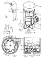
- a shooter uses a weapon 1, for example an air rifle for so-called paintballs, which over a flexible delivery hose 2 connected to the ball container 3 that contains the ammunition bullets.
- a weapon for example an air rifle for so-called paintballs, which over a flexible delivery hose 2 connected to the ball container 3 that contains the ammunition bullets.
- These will via the conveyor described later in a closed row through the delivery hose 2 to the projectile chamber of the rifle 1 promoted. They are under a spring force, so that whenever a bullet is shot and the empty one Bullet chamber opens, a new ball from the delivery hose 2 or from the channel in the weapon to which the The outlet end of the delivery hose 2 connects into the storey chamber is pressed.
- the ball container 3 is on the belt 4 of the Protect attached.
- the ball container 3 is cylindrical and provided with a closure cap 5, which schematically indicated compression spring 6 connected to a pressure plate 7 is. This presses under the action of the spring 6 Container content away from the open, closed by the lid 5 Container end towards its other end.
- the conveyor 8 which is shown in FIG is only indicated schematically and the balls in promotes the outlet channel 9 of the ball container 3, which to the Inlet end of the delivery hose 2 is connected.
- the sponsor 8 is later through an electric motor 10 descriptive clutch 11 driven.
- the engine 10 is from a not shown, at a suitable location in the container 3 provided battery powered. Using hook 12 the container can be attached to the belt 4 of the shooter.
- a coupling device 13 can be selected Attachment of the container to the weapon may be provided.
- the spring plate 7 ensures that the contained in the container Balls are also fed to the conveyor 8 when the container 3 is not vertical.
- a disc 20 formed concentrically in a cylindrical part 21 of the Container 3 arranged on a shaft 22 and by means of the motor 10 is driven to rotate in the direction of arrow 28.
- the Disk 20 turns the container space 13 a flat or curved Surface 23 to.
- the disk 20 carries one on its circumference Wreath of projections 24 and recesses located between them 25 with the inner surface 26 receiving cells for Form balls 27 that are larger than the balls. Under the Effect of gravity or spring plates 7 reach it Balls 27 therefore easily get into and out of these cells added.
- the direction of rotation 30 can rear lying edge 31 of the receiving cells 25 beveled in this way be that he continues the ball falling into a receiving cell 27 urges downward in the direction of arrow 32. This also contributes the relative movement compared to the standing ones above Balls, one of which is indicated at 33.
- the task of the receiving cells 25 consists exclusively of the balls easy to pick up and they explained later To supply funding bodies. You have no funding role yourself. You may deserve protection regardless of the under Features described in claim 1. Her size can be measured freely from the single point of view, that the balls easily find their way into the receiving cells and easily forwarded down by them. In order to bullets can also be caught that are not in the Outside of the container, but located further radially inside, the receiving cells can be expanded inwards be, as indicated by the dot-dash line in FIG. 3 at 34 , the area 35 between the dash-dotted line 34 and the edge of the receiving cell 25 falling at an angle can be designed for the receiving cell that the balls be guided into the desired, radially outer position, in which can be taken by the funding bodies.
- inclined surface 35 on the disc 20 can also be provided be that the open cross section of the receiving cells 25 radially is extended inwards according to line 34 and below the disc 20 has a corresponding inclined surface on a base 39 is provided. Sloping surfaces on the base 39 and on the disc 20 can also be provided in addition to each other his.
- the axes of rotation of the rollers 41 are somewhat further from the inner surface 26 of the wall 21 removed as the radius 43 of the balls corresponds.
- the radius of their orbit 44 is therefore 45 less than the radius of the orbit 46 the centers of the balls 27, if they are both on the floor 40 as well as on the inner surface 26 of the wall 21 (Fig. 10). Therefore, the tangent to the (theoretically punctiform) Contact surface 49 of the roller 41 with a radius acute angle alpha.
- the direction of the conveyor 48, the is exerted by the roller 41 on the associated ball 27, does not run in the circumferential direction, but has an outward direction directed component through which the ball 27 in contact the inner surface 26 of the wall 21 is held.
- a further beveling of the contact surface 49 is used for this concerned that the balls 27 when they are in the conveying position (Figs. 9 and 10) are always in contact with the Floor 40 are held.
- the surface 47 of the rollers 41 is namely conical, so that the contact surface 49th does not run perpendicularly, but in the section of FIG. 9 is slightly inclined downwards, behind the angle Beta.
- the conveying force exerted on the ball 27 contains 48 a component directed downwards towards the floor 40, through which the ball is pressed against the ground.
- the conveying position of the balls is very simple, the safest and most precise way, namely on the one hand through the bottom surface 40 and the peripheral surface 26 and on the other hand through the role 41. This applies regardless of any positional tolerances of the roller 41, provided that the above geometric conditions are met.
- the invention Conveying device therefore works very safely and with little interference.
- the contact surface 49 does not necessarily have to be on a roll 41 be formed; rather, it can also be fixed to the Washer 20 may be arranged.
- the execution as a roller surface has the advantage that the friction is reduced.
- If the Contact surface 47 is formed by a roller surface can take part in this movement without inhibiting it. It is particularly advantageous if the roller 41 is arranged in this way is that its axis of rotation is parallel to that of the associated ball 27 runs, that is at about 45 ° to the floor surface 40; however, there will be a significant reduction in friction already reached when the roller axis 42 for reasons the simpler manufacture deviating from this ideal direction is positioned.
- the base 39 with a corresponding Be provided circumferential surface 38 the distance from the inner surface 26 of the wall 21 is so large that the balls 27 do not touch the surface 38 when it is in the Funding position.
- the outlet duct 9 is tangential to the wall 21 such that its central axis 50 is tangent to the central path 46 of the balls forms. In addition, the Outlet channel 9 continuously to the floor 40.
- the height of the surface 23 of the disc 20 above the floor 40 is not significantly smaller or even a little larger than the diameter of the balls 27 to reduce the resistance, which the stationary balls moved onto those below them Exercise balls in the conveying position.
- the receiving cell just emptied into the delivery channel 9 51 does not prematurely refill what is under certain conditions could lead to complications a housing-fixed filler 52 is provided to prevent this. Only when the cell 51 completes the filler 52 happened, it can fill up again.
- the filler 52 has no function in directing the balls 27 into the outlet channel 9. This is because they are directed outwards Component of the conveying force 48 in contact with the radial outer surface of the conveying channel are kept and thus cannot touch the filler 52.
- this spring device from the conveyor hose and / or the row of balls formed.
- the The hose Under the conveying force, the The hose is elastic and produces a force corresponding to the conveying force Restoring force. Accordingly, those in the funding series located balls are elastically compressed by the conveying force. If the sum of the elastic elongation of the hose and the elastic compression of the row of balls is larger than at least one ball diameter, they can the transfer of the pending ball into the storey chamber through elastic contraction or expansion if the engine is not switched on. The same thing also applies to several balls in succession if the elongation of the hose or the compression of the row of balls accordingly is great.
- clutch 11 can be used to measure this torque be formed and falling below a predetermined Torque threshold to the electronics controlling the engine report, which then switches on the motor. Vice versa it switches the engine off when the clutch 11 exceeds reports a predetermined torque threshold.
- a special one Design of the spring device for example can be arranged in the clutch 11 and schematically is constructed as shown in Fig. 11.
- the inner clutch part 52 is by the motor 10 in the direction of the arrow driven.
- the concentric outer one Coupling part 53 is connected to the shaft 22 of the conveyor.
- the two coupling parts 52, 53 have each other in the circumferential direction opposing stops 54, 55, between which acts a compression spring 56. This is due to the rotation of the driving coupling part 52 and the resistance of the row of balls compressed.
- One of the coupling parts (shown in the Case the outer) is with contacts or limit switches 57, 58 and the other coupling part are provided with a cam 59, that interacts with it.
- contact 57 When exceeding a certain Length of the spring 46 and thus when falling below one Torque threshold acting between the coupling parts contact 57 is closed. His signal does that Starting the engine. This compresses the spring 56, and cam 59 moves away from contact 57 while he is approaching contact 58. As soon as a limit torque is reached that corresponds to the desired conveying force the contact 58 is activated, which causes the motor to be switched off.
- FIG. 12 shows the possibility of a primary ball container 3 to add another ball container 3a.
- the sponsor the further ball container 3a promotes those located therein Balls via a hose 61 in a provided on the ball container 3 Receiving opening 62.
- the two ball containers 3, 3a connected in parallel and promote the balls directly or via a hose 61 into the conveying hose 2.
Abstract
Description
- Fig. 1
- die erfindungsgemäße Vorrichtung bei der Verwendung,
- Fig. 2
- den teilweise geschnittenen Kugelbehälter und den Förderer in auseinandergezogener Darstellung,
- Fig. 3
- einen Querschnitt durch den Kugelbehälter mit Blickrichtung auf den Förderer,
- Fig. 4
- einen Teil-Längsschnitt durch den Kugelbehälter mit dem Förderer,
- Fig. 5 bis 7
- Querschnitte durch den Kugelbehälter im Bereich des Förderers in unterschiedlichen Funktionsstadien,
- Fig. 8 und 9
- Teil-Längsschnitte durch den Förderer in größerem Maßstab,
- Fig. 10
- einen Teilquerschnitt durch den Förderer in größerem Maßstab,
- Fig. 11
- die schematische Darstellung einer Drehkupplung mit Federeinrichtung und Abtastung des Federwegs und
- Fig. 12 und 13
- gekoppelte Anordnungen zweier Kugelbehälter.
Claims (11)
- Vorrichtung zum Magazinieren von Geschoßkugeln (27) und zum Zuführen derselben zur Geschoßkammer einer Handfeuerwaffe (1) mit einem Kugelbehälter (3), einem daran mit seinem einen Ende angeschlossenen Förderrohr (2), dessen anderes Ende zur Waffe (1) führt, und einem von einem Motor (10) angetriebenen Förderer (20) zum Fördern von Kugeln aus dem Kugelbehälter in das Förderrohr (2), wobei eine Einrichtung zum intermittierenden Einschalten des Motors (10) vorgesehen ist, dadurch gekennzeichnet, daß der Förderer (20) zur Aufrechterhaltung einer ständig auf die Kugelreihe ausgeübten, von einer Federeinrichtung (2, 56) gespeicherten Förderkraft ausgebildet ist, deren Federweg mindestens so groß ist, wie der Durchmesser einer Kugel (27, und die Einrichtung (57, 58, 59) zum intermittierenden Einschalten des Motors (10) abhängig ist von dem Zustand der Federeinrichtung (2, 56).
- Vorrichtung nach Anspruch 1, dadurch gekennzeichnet, daß die Federeinrichtung zumindest teilweise von einem an dem Förderer vorgesehenen, besonderen Teil (56) gebildet ist.
- Vorrichtung nach Anspruch 1 oder 2, dadurch gekennzeichnet, daß die Federeinrichtung zumindest teilweise von der elastischen Kugelreihe bzw. dem Förderschlauch (2) gebildet ist.
- Vorrichtung nach einem der Ansprüche 1 bis 3, dadurch gekennzeichnet, daß das Förderrohr (2) als flexibler Förderschlauch ausgebildet, der Kugelbehälter (3) mit einer waffenunabhängigen Traghalterung (12) versehen und der Motor (20) mit einer waffenunabhängigen Energieversorgung ausgerüstet ist.
- Vorrichtung nach einem der Ansprüche 1 bis 4, dadurch gekennzeichnet, daß die Einrichtung (57, 58, 59) zum intermittierenden Einschalten des Motors (10) vom Unter-bzw. Überschreiten der Förderkraft bzw. des Federwegs abhängig ist.
- Vorrichtung nach einem der Ansprüche 1 bis 5, dadurch gekennzeichnet, daß der Kugelbehälter (3) oder der Förderer (20) oder der Förderschlauch (2) mit einer Anschlußöffnung (62) zum Anschluß des Auslasses (9) eines weiteren Kugelbehälters versehen ist.
- Vorrichtung nach einem der Ansprüche 1 bis 5, dadurch gekennzeichnet, daß mehrere Kugelbehälter (3, 3a) parallel geschaltet sind.
- Vorrichtung nach einem der Ansprüche 1 bis 7, dadurch gekennzeichnet, daß der Kugelbehälter (3) eine den Kugelvorrat unter der Wirkung einer Feder (6) in Richtung zum Förderer (8) drückende Druckplatte (7) enthält.
- Vorrichtung nach einem der Ansprüche 1 bis 8, dadurch gekennzeichnet, daß der Förderer (3) einen Rotor (20) mit einer Mehrzahl am Umfang verteilter Vorsprünge (24) umfaßt, die zwischen einander und einer konzentrisch zu dem Rotor (20) angeordneten Wandung (21) Räume (25) für je eine Kugel (27) bilden, wobei jeder Vorsprung (24) in Umlaufrichtung der Kugel eine Mitnehmerfläche (49) zuwendet und daß oberhalb des die Mitnehmerfläche (49) bildenden Teils (41) des Förderers (20) eine drehend angetriebene Scheibe (20) mit einem Kranz von Vorsprüngen (24) und dazwischen befindlichen Aufnahmezellen (25) vorgesehen ist, deren Weite beträchtlich größer als die Ausdehnung einer Kugel (27) ist.
- Vorrichtung nach Anspruch 9, dadurch gekennzeichnet, daß die Mitnehmerfläche (49) gegenüber der Radiusrichtung (Winkel Alpha) und der Achsrichtung (Winkel Beta) derart geneigt ist, daß die mitgenommene Kugel (27) gegen eine zur Rotorebene parallele Bodenfläche (40) und gegen die Innenfläche (26) der Wandung (21) und in eine der Wandung enthaltene Auslaßöffnung (9) gedrückt wird, die mit dem Förderschlauch (2) verbunden ist.
- Vorrichtung nach einem der Ansprüche 1 bis 10, dadurch gekennzeichnet, daß oberhalb des Förderers (8) an der Behälterwand ein ringförmig umlaufender Kragen (60) vorgesehen ist.
Applications Claiming Priority (2)
| Application Number | Priority Date | Filing Date | Title |
|---|---|---|---|
| DE19922589 | 1999-05-17 | ||
| DE19922589A DE19922589A1 (de) | 1999-05-17 | 1999-05-17 | Vorrichtung zum Magazinieren von Geschoßkugeln und zum Zuführen derselben zur Geschoßkammer einer Handfreuerwaffe |
Publications (2)
| Publication Number | Publication Date |
|---|---|
| EP1054228A2 true EP1054228A2 (de) | 2000-11-22 |
| EP1054228A3 EP1054228A3 (de) | 2001-12-12 |
Family
ID=7908282
Family Applications (1)
| Application Number | Title | Priority Date | Filing Date |
|---|---|---|---|
| EP00104822A Withdrawn EP1054228A3 (de) | 1999-05-17 | 2000-03-06 | Vorrichtung zum Magazinieren von Geschosskugeln und zum Zuführen derselben zur Geschosskammer einer Handfeuerwaffe |
Country Status (3)
| Country | Link |
|---|---|
| US (1) | US6327953B1 (de) |
| EP (1) | EP1054228A3 (de) |
| DE (1) | DE19922589A1 (de) |
Cited By (11)
| Publication number | Priority date | Publication date | Assignee | Title |
|---|---|---|---|---|
| WO2003025492A1 (en) * | 2001-09-19 | 2003-03-27 | Fn Herstal | Less-lethal launcher |
| GB2363188B (en) * | 2000-06-08 | 2004-02-25 | Airgun Designs Inc | Paintball feeders |
| EP1495279A1 (de) * | 2002-04-12 | 2005-01-12 | National Paintball Supply, Inc. | Differentialerfassungssystem zur steuerung der zuführung eines paintball-laders |
| WO2006040171A1 (en) * | 2004-10-14 | 2006-04-20 | Aj Acquisition I Llc | Procedure and device for feeding balls into the projectile chamber of a handgun |
| US7654255B2 (en) | 2005-10-06 | 2010-02-02 | Kee Action Sports I Llc | Self-regulation paintball agitator system |
| US8387607B2 (en) | 2004-04-28 | 2013-03-05 | Kee Action Sports I Llc | Mechanical drive assist for paintball loader |
| US8561600B2 (en) | 1999-12-16 | 2013-10-22 | Kee Action Sports I Llc | Paintball loader |
| US9658027B2 (en) | 2013-06-21 | 2017-05-23 | Gi Sportz Direct Llc | Compressed gas gun having built-in, internal projectile feed mechanism |
| USD961002S1 (en) | 2019-12-30 | 2022-08-16 | Kore Outdoor (Us), Inc. | Projectile loader |
| USD992671S1 (en) | 2020-10-08 | 2023-07-18 | Canadian Imperial Bank Of Commerce, As Agent | Projectile launcher and loader |
| US11796280B2 (en) | 2019-11-26 | 2023-10-24 | Kore Outdoor (Us), Inc. | Projectile loader having streamlined external body and internal opening mechanism |
Families Citing this family (42)
| Publication number | Priority date | Publication date | Assignee | Title |
|---|---|---|---|---|
| US6305367B1 (en) | 1999-02-26 | 2001-10-23 | Airgun Designs, Inc. | Hopper feeder |
| US6792933B2 (en) * | 1999-12-16 | 2004-09-21 | National Paintball Supply, Inc. | Drive cone for paintball loader |
| US6701907B2 (en) * | 1999-12-16 | 2004-03-09 | National Paintball Supply, Inc. | Spring loaded feed mechanism for paintball loader |
| USRE45986E1 (en) | 1999-12-16 | 2016-04-26 | Gi Sportz Direct Llc | Spring loaded feed mechanism for paintball loader |
| US6978776B2 (en) * | 2003-03-19 | 2005-12-27 | Ancient Innovations Corp. | Multiple column helical feeder |
| US20050188973A1 (en) * | 2004-02-17 | 2005-09-01 | Planet Eclipse Ltd. | Rotary bolt |
| US7270121B2 (en) * | 2004-06-14 | 2007-09-18 | Curtis Robert Lubben | Paintball backpack hopper with positive feed device to deliver paintballs to a paintball gun without jamming problems |
| US7428899B2 (en) * | 2004-10-14 | 2008-09-30 | Kee Action Sports I Llc | Device for storing projectile balls and feeding them into the projectile chamber of a gun |
| US7234456B2 (en) * | 2004-10-14 | 2007-06-26 | Kee Action Sports | Device for feeding balls into the ball chamber of a handgun |
| DE602004027635D1 (de) * | 2004-10-26 | 2010-07-22 | Dye Precision Inc | Paintball-Ladevorrichtung |
| US7694669B2 (en) | 2004-12-08 | 2010-04-13 | Kee Action Sports I, Llc | Paintball loader feed mechanism |
| US20060157042A1 (en) * | 2005-01-14 | 2006-07-20 | Rincon Marco A | Apparatus for storing and dispensing paintballs and propellant |
| US20060283431A1 (en) * | 2005-01-31 | 2006-12-21 | Lee David W | Non-lethal projectile belt and feeding apparatus |
| US7357130B2 (en) * | 2005-05-05 | 2008-04-15 | Jt Usa, Llc | Spring-assisted paintball loader |
| US8100119B2 (en) * | 2005-05-13 | 2012-01-24 | Hall David L | Paintball system |
| US7921835B2 (en) | 2005-09-15 | 2011-04-12 | Kee Action Sports I Llc | Wireless projectile loader system |
| US7832389B2 (en) | 2005-10-11 | 2010-11-16 | Kee Action Sports I Llc | Magnetic drive bypass system for paintball loader |
| US8251050B2 (en) | 2005-10-11 | 2012-08-28 | Kee Action Sports I Llc | Magnetic drive bypass system for paintball loader |
| US7322348B2 (en) * | 2005-11-02 | 2008-01-29 | Speed Paintball Co., Ltd. | Electric paintball feed hopper for paintguns |
| US7594502B1 (en) | 2005-12-07 | 2009-09-29 | Anderson Joel A | Projectile loading, firing and warning system |
| US7559445B1 (en) | 2005-12-17 | 2009-07-14 | Donald Lee Kulp | Paintball pod carrier |
| US7617817B1 (en) | 2005-12-19 | 2009-11-17 | Donald Lee Kulp | Low profile paintball loader mount |
| US7806036B2 (en) * | 2006-01-03 | 2010-10-05 | Browning | Magazine apparatuses, firearms including same, and method of introducing an ammunition cartridge into a firearm |
| WO2007139934A2 (en) | 2006-05-25 | 2007-12-06 | Kee Action Sports I Llc | Self-regulating valve assembly |
| CA2658457A1 (en) | 2006-07-19 | 2008-01-24 | Procaps L.P. | Paintball gun loading methods and apparatus |
| US20080047535A1 (en) * | 2006-08-24 | 2008-02-28 | Brandon Handel | Paintball quick change hopper |
| US8156675B2 (en) | 2007-03-08 | 2012-04-17 | Browning | Firearm magazine |
| US7975681B2 (en) | 2007-10-03 | 2011-07-12 | Brandon Handel | Spherical projectile reloading system |
| US8402959B1 (en) | 2008-03-19 | 2013-03-26 | Kee Action Sports I Llc | Magnetic force feed projectile feeder drive mechanism |
| US8047190B2 (en) * | 2008-10-20 | 2011-11-01 | Dye Precision, Inc. | Paintball loader |
| US8402958B2 (en) * | 2009-08-21 | 2013-03-26 | Hasbro, Inc. | Toy dart magazine apparatus |
| US8235030B2 (en) | 2010-05-25 | 2012-08-07 | Dye Precision, Inc. | Paintball loader |
| KR101282903B1 (ko) * | 2012-11-26 | 2013-07-05 | 강현민 | 서바이벌게임용 완구총기 |
| EP3062058B1 (de) * | 2015-02-24 | 2018-05-09 | Xeon Paintball AB | Paintball-lader |
| DE102015104004B4 (de) | 2015-03-18 | 2022-03-17 | Maxxloader Ltd. | Paintball-Rucksack zum Lagern, Transportieren und/oder Fördern von Geschossen |
| WO2018057644A1 (en) | 2016-09-21 | 2018-03-29 | Browning | Firearm magazine |
| US11340037B1 (en) * | 2017-12-21 | 2022-05-24 | Easebon Services Limited | Easy loading toy projectile launcher |
| US10648763B2 (en) * | 2017-12-21 | 2020-05-12 | Easebon Services Limited | Easy loading toy projectile launcher |
| US10648767B2 (en) * | 2017-12-21 | 2020-05-12 | Easebon Services Limited | Easy loading toy projectile launcher |
| US11346624B2 (en) * | 2019-10-07 | 2022-05-31 | Hasbro, Inc. | Projectile loading system for toy launcher and methods |
| US11732997B2 (en) * | 2020-08-26 | 2023-08-22 | Kyle Buckmaster | Apparatus and methods for paintball feeding mechanism |
| CN113280677A (zh) * | 2021-05-13 | 2021-08-20 | 华南理工大学 | 一种可转换方向的双通道切向送丸料装置 |
Citations (14)
| Publication number | Priority date | Publication date | Assignee | Title |
|---|---|---|---|---|
| US3788298A (en) | 1972-06-19 | 1974-01-29 | Victor Comptometer Corp | Compressed gas gun with trigger operated hammer release latching structure |
| DE8314931U1 (de) | 1983-05-20 | 1983-12-08 | C. Riethmüller GmbH, 7312 Kirchheim | Watteball-pistole |
| DE3721527C2 (de) | 1987-06-30 | 1989-05-03 | Heckler & Koch Gmbh, 7238 Oberndorf, De | |
| US5063905A (en) | 1990-09-06 | 1991-11-12 | Farrell Kenneth R | Pneumatic gun |
| US5097816A (en) | 1990-08-21 | 1992-03-24 | Miller John D | Projectile container for use with a device that selectively discharges fragile projectiles, such as paintballs, under the influence of a source of fluid pressure |
| US5282454A (en) | 1992-10-20 | 1994-02-01 | Cm Support, Inc. | Jam-free bulk loader for a paintball gun |
| US5505188A (en) | 1994-03-17 | 1996-04-09 | Williams; Robert A. | Paint ball gun |
| US5511333A (en) | 1995-02-23 | 1996-04-30 | Farrell; Kenneth R. | Paintball clip magazine |
| WO1998013660A1 (en) | 1996-09-25 | 1998-04-02 | Rudy Viviani | Pneumatic drive unit |
| US5736720A (en) | 1996-08-29 | 1998-04-07 | Cm Support, Inc. | Loader mounted paintball game scorekeeper and an associated paintball game playing system |
| US5771875A (en) | 1995-04-28 | 1998-06-30 | Sullivan; Brian E. | Gas powered repeating gun |
| US5794606A (en) | 1996-05-28 | 1998-08-18 | Deak; Bernard A. | Ram feed ammo box |
| US5816232A (en) | 1997-05-15 | 1998-10-06 | Cm Support, Inc. | Paintball loader having active feed mechanism |
| US5839422A (en) | 1997-05-23 | 1998-11-24 | Ferris; Shell M. | Automatic feeder for projectile gun using compressed gas |
Family Cites Families (24)
| Publication number | Priority date | Publication date | Assignee | Title |
|---|---|---|---|---|
| US1404689A (en) | 1922-01-24 | Air gun | ||
| US1403719A (en) | 1921-03-05 | 1922-01-17 | Keystone Die And Mfg Company | Toy gun |
| US1743576A (en) | 1927-07-14 | 1930-01-14 | Smith Robert Bigham | Pneumatically-actuated machine gun |
| US1867513A (en) * | 1930-07-05 | 1932-07-12 | Lahti Aimo Johannes | Cartridge case |
| US2398263A (en) * | 1941-03-20 | 1946-04-09 | Curtiss Wright Corp | Multiple ammunition boxes |
| US2357951A (en) * | 1941-08-19 | 1944-09-12 | Saint Cyr Corp | Pneumatic gun |
| US3248008A (en) | 1964-09-03 | 1966-04-26 | Meierjohan Ernest | Golf ball dispenser or the like |
| US3467073A (en) * | 1966-03-28 | 1969-09-16 | Barry V Rhodes | Automatic ball throwing machine |
| US3610223A (en) | 1970-03-02 | 1971-10-05 | Wallace V Green | Automatically operated spring-type projectile projecting device |
| US3695246A (en) | 1971-06-10 | 1972-10-03 | Us Navy | Pneumatic machine gun with photo cell interrupted circuit |
| FR2206678A5 (de) | 1972-11-13 | 1974-06-07 | Rhone Poulenc Sa | |
| US3844267A (en) | 1973-05-07 | 1974-10-29 | J Mohr | Tennis ball pitching apparatus with anti-jamming ball feed mechanism |
| US4207857A (en) | 1978-05-18 | 1980-06-17 | Balka William J Jr | Automatic ball server |
| US4332097A (en) * | 1979-10-01 | 1982-06-01 | Taylor Jr William J | Drum magazine for automatic pistol or the like |
| US4926742A (en) * | 1986-10-16 | 1990-05-22 | Poly Technologies, Inc. | Spiral drum magazine with elongated magazine clip and single piece last round follower |
| GB8812464D0 (en) * | 1988-05-26 | 1988-08-24 | Lucas Ind Plc | Apparatus & method for supply of belt-linked ammunition |
| US4965951A (en) * | 1988-10-20 | 1990-10-30 | Miller Michael K | Large capacity ammunition magazine |
| AT395681B (de) * | 1991-01-04 | 1993-02-25 | Salansky Werner | Ballwurfmaschine, insbesondere fuer tennisbaelle |
| DE4343870A1 (de) * | 1993-12-22 | 1994-06-30 | Frederik Wuesthoff | Ladevorrichtung für endlosen Munitionsnachschub einer automatischen Schußwaffe |
| US5520171A (en) * | 1994-04-04 | 1996-05-28 | Helitek | Indexing helical magazine |
| US5881962A (en) * | 1994-04-11 | 1999-03-16 | Autoliv Development Ab | Mass-body drive for a rotary tightening device |
| US5722383A (en) * | 1995-12-01 | 1998-03-03 | Tippmann Pneumatics, Inc. | Impeder for a gun firing mechanism with ammunition feeder and mode selector |
| GB9706988D0 (en) * | 1997-04-05 | 1997-05-21 | Stevens Simon B | Multi-directional projectile feeder |
| US5954042A (en) * | 1997-11-10 | 1999-09-21 | Harvey; Daniel D. | Paintball loader |
-
1999
- 1999-05-17 DE DE19922589A patent/DE19922589A1/de not_active Withdrawn
- 1999-06-08 US US09/327,818 patent/US6327953B1/en not_active Expired - Lifetime
-
2000
- 2000-03-06 EP EP00104822A patent/EP1054228A3/de not_active Withdrawn
Patent Citations (14)
| Publication number | Priority date | Publication date | Assignee | Title |
|---|---|---|---|---|
| US3788298A (en) | 1972-06-19 | 1974-01-29 | Victor Comptometer Corp | Compressed gas gun with trigger operated hammer release latching structure |
| DE8314931U1 (de) | 1983-05-20 | 1983-12-08 | C. Riethmüller GmbH, 7312 Kirchheim | Watteball-pistole |
| DE3721527C2 (de) | 1987-06-30 | 1989-05-03 | Heckler & Koch Gmbh, 7238 Oberndorf, De | |
| US5097816A (en) | 1990-08-21 | 1992-03-24 | Miller John D | Projectile container for use with a device that selectively discharges fragile projectiles, such as paintballs, under the influence of a source of fluid pressure |
| US5063905A (en) | 1990-09-06 | 1991-11-12 | Farrell Kenneth R | Pneumatic gun |
| US5282454A (en) | 1992-10-20 | 1994-02-01 | Cm Support, Inc. | Jam-free bulk loader for a paintball gun |
| US5505188A (en) | 1994-03-17 | 1996-04-09 | Williams; Robert A. | Paint ball gun |
| US5511333A (en) | 1995-02-23 | 1996-04-30 | Farrell; Kenneth R. | Paintball clip magazine |
| US5771875A (en) | 1995-04-28 | 1998-06-30 | Sullivan; Brian E. | Gas powered repeating gun |
| US5794606A (en) | 1996-05-28 | 1998-08-18 | Deak; Bernard A. | Ram feed ammo box |
| US5736720A (en) | 1996-08-29 | 1998-04-07 | Cm Support, Inc. | Loader mounted paintball game scorekeeper and an associated paintball game playing system |
| WO1998013660A1 (en) | 1996-09-25 | 1998-04-02 | Rudy Viviani | Pneumatic drive unit |
| US5816232A (en) | 1997-05-15 | 1998-10-06 | Cm Support, Inc. | Paintball loader having active feed mechanism |
| US5839422A (en) | 1997-05-23 | 1998-11-24 | Ferris; Shell M. | Automatic feeder for projectile gun using compressed gas |
Cited By (15)
| Publication number | Priority date | Publication date | Assignee | Title |
|---|---|---|---|---|
| US8561600B2 (en) | 1999-12-16 | 2013-10-22 | Kee Action Sports I Llc | Paintball loader |
| US9970733B2 (en) | 1999-12-16 | 2018-05-15 | Gi Sportz Direct Llc | Paintball loader |
| GB2363188B (en) * | 2000-06-08 | 2004-02-25 | Airgun Designs Inc | Paintball feeders |
| WO2003025492A1 (en) * | 2001-09-19 | 2003-03-27 | Fn Herstal | Less-lethal launcher |
| EP1495279A1 (de) * | 2002-04-12 | 2005-01-12 | National Paintball Supply, Inc. | Differentialerfassungssystem zur steuerung der zuführung eines paintball-laders |
| US10024624B2 (en) | 2002-04-12 | 2018-07-17 | Gi Sportz Direct Llc | Paintball loader drive system |
| EP1495279A4 (de) * | 2002-04-12 | 2010-07-21 | Nat Paintball Supply Inc | Differentialerfassungssystem zur steuerung der zuführung eines paintball-laders |
| US8387607B2 (en) | 2004-04-28 | 2013-03-05 | Kee Action Sports I Llc | Mechanical drive assist for paintball loader |
| WO2006040171A1 (en) * | 2004-10-14 | 2006-04-20 | Aj Acquisition I Llc | Procedure and device for feeding balls into the projectile chamber of a handgun |
| US7654255B2 (en) | 2005-10-06 | 2010-02-02 | Kee Action Sports I Llc | Self-regulation paintball agitator system |
| US9658027B2 (en) | 2013-06-21 | 2017-05-23 | Gi Sportz Direct Llc | Compressed gas gun having built-in, internal projectile feed mechanism |
| US11796280B2 (en) | 2019-11-26 | 2023-10-24 | Kore Outdoor (Us), Inc. | Projectile loader having streamlined external body and internal opening mechanism |
| USD961002S1 (en) | 2019-12-30 | 2022-08-16 | Kore Outdoor (Us), Inc. | Projectile loader |
| USD984549S1 (en) | 2019-12-30 | 2023-04-25 | Kore Outdoor (Us), Inc. | Projectile loader |
| USD992671S1 (en) | 2020-10-08 | 2023-07-18 | Canadian Imperial Bank Of Commerce, As Agent | Projectile launcher and loader |
Also Published As
| Publication number | Publication date |
|---|---|
| US6327953B1 (en) | 2001-12-11 |
| EP1054228A3 (de) | 2001-12-12 |
| DE19922589A1 (de) | 2000-12-07 |
Similar Documents
| Publication | Publication Date | Title |
|---|---|---|
| EP1054228A2 (de) | Vorrichtung zum Magazinieren von Geschosskugeln und zum Zuführen derselben zur Geschosskammer einer Handfeuerwaffe | |
| EP1265049B1 (de) | Magazin für luftdruckwaffengeschosse und behälter zum lagern von geschossen für ein solches magazin | |
| DE3021200A1 (de) | Feuerwaffe mit einem schutzsystem gegen verspaetetes losgehen oder nachzuenden | |
| DE10125202A1 (de) | Farbkugelzuführer | |
| EP0277311B1 (de) | Sicherheitsvorrichtung an einem Fremdangetriebenen Geschütz | |
| DE1578457B2 (de) | Sicherungseinrichtung fuer aufschlagzuender | |
| EP0290031B1 (de) | Vorrichtung zum Zuführen von Munition aus einem Munitionsbehälter zu einer automatischen Feuerwaffe | |
| DE1014886B (de) | Patronenzufuehrungsvorrichtung fuer automatische Waffen | |
| DE19501706B4 (de) | Munitionszuführungssystem für eine Feuerwaffe | |
| EP0184008A1 (de) | Ueberwachungseinrichtung von Spätzündern für ein fremdangetriebenes Geschütz | |
| DE3219800C2 (de) | Vorrichtung zum Zuführen von Munition zu einer Maschinenwaffe | |
| CH657698A5 (de) | Maschinenkanone vom gatling-typ. | |
| DE3427875C1 (de) | Automatische Feuerwaffe mit walzenfoermigem Verschlussteil | |
| EP0529289A1 (de) | Vorrichtung zum Zuführen von Patronen vorwiegend zweier verschiedener Munitionsarten zu einer Gatling-Kanone | |
| DE1099905B (de) | Manoeverpatrone fuer Maschinenwaffen | |
| EP0111780B1 (de) | Fördervorrichtung zum Zuführen von Patronen zu einer Feuerwaffe aus einem Trommelmagazin | |
| DE3809319A1 (de) | Zylinderfoermiges magazin fuer schusswaffen | |
| DE2656710A1 (de) | Drehwalzenwendelfoerder-magazin | |
| DE3048750A1 (de) | "vorrichtung zum vereinzelten zufuehren von gegenstaenden, insbesondere kugeln" | |
| DE2714085C3 (de) | Verzögerungsvorrichtung für Drallgeschoßzünder | |
| DE4140843C1 (en) | Light machine gun with multi-shaft cartridge magazine - has magazine shafts sepd. by partitions,with cartridges transverse to firing direction | |
| EP2095871B1 (de) | Dosiervorrichtung für Feststoffpellets einer Ammoniak abspaltenden Substanz | |
| DE3144241C2 (de) | Vorrichtung zum Ausrichten und Magazinieren von elastischen, ringförmigen Körpern | |
| EP0525373B1 (de) | Vorrichtung zum Zuführen von Patronen vorwiegend zweier verschiedener Munitionsarten zu einer Gatling-Kanone | |
| AT20419B (de) | Vorrichtung zum Zubringen und Einführen der Ladung bei in Geschütztürmen. |
Legal Events
| Date | Code | Title | Description |
|---|---|---|---|
| PUAI | Public reference made under article 153(3) epc to a published international application that has entered the european phase |
Free format text: ORIGINAL CODE: 0009012 |
|
| AK | Designated contracting states |
Kind code of ref document: A2 Designated state(s): AT BE CH CY DE DK ES FI FR GB GR IE IT LI LU MC NL PT SE |
|
| AX | Request for extension of the european patent |
Free format text: AL;LT;LV;MK;RO;SI |
|
| PUAL | Search report despatched |
Free format text: ORIGINAL CODE: 0009013 |
|
| AK | Designated contracting states |
Kind code of ref document: A3 Designated state(s): AT BE CH CY DE DK ES FI FR GB GR IE IT LI LU MC NL PT SE |
|
| AX | Request for extension of the european patent |
Free format text: AL;LT;LV;MK;RO;SI |
|
| RIC1 | Information provided on ipc code assigned before grant |
Free format text: 7F 41B 11/02 A, 7F 41A 9/73 B, 7F 41A 9/02 B |
|
| GRAH | Despatch of communication of intention to grant a patent |
Free format text: ORIGINAL CODE: EPIDOS IGRA |
|
| 17P | Request for examination filed |
Effective date: 20020610 |
|
| AKX | Designation fees paid |
Free format text: AT BE CH CY DE DK ES FI FR GB GR IE IT LI LU MC NL PT SE |
|
| STAA | Information on the status of an ep patent application or granted ep patent |
Free format text: STATUS: THE APPLICATION IS DEEMED TO BE WITHDRAWN |
|
| 18D | Application deemed to be withdrawn |
Effective date: 20030130 |