FIELD OF THE INVENTION AND RELATED ART
The present invention relates to a holder for
containing ink to be supplied to recording means, a
holder on which the ink container is mounted, an ink
jet recording apparatus provided with the holder and a
mounting method for mounting the ink container to the
holder, wherein the mounting property is improved.
An ink jet recording apparatus is known which
comprises a recording head for effecting recording on
a recording material by ejecting the ink, an ink
container for accommodating the ink to be supplied to
the recording head and a container holder for
detachably mountably holding the ink container, the
container holder having the recording head. Among
such apparatuses, a color printer capable of color
printing has recording heads for magenta, yellow, cyan
and black inks, and ink containers corresponding to
recording head are exchangeable at specified positions
in the holder.
Various methods for preventing mounting at
erroneous position in such a recording device have
been made to assure the mounting at the correct
positions.
For example, the position in the holder
determined for the respective colors are recognized by
a label; a warning display is effected in response to
detection of an erroneous mounting of the container
after the container mounting; or the erroneous
mounting is detected on the basis of an abnormality in
the image when the printing is effected.
In a second example, configurations of the
joint portion of the ink container for connection with
an ink supply port of a recording head portion are
made different for the colors to prevent the erroneous
mounting. In a third example, a projection is
provided outside the ink container, and the container
holder is provided with a corresponding to the
projection is provided, and such discrimination
structure is made different for the respective colors.
Recently, the ink jet printer has been
improved in the image quality, and greater kinds of
inks are used. For example, it is known that two
different inks are chemically reacted on the surface
of the sheet of paper by which the ink is fixed
thereon with improved water-resistance and wearing
property, in such a case, if the ink container were
erroneously mounted, the functions of the recording
head per se and the quality of the recorded image are
seriously damaged.
However, with the conventional erroneous
mounting prevention function is not satisfactory. In
the first example, the erroneous mounting is detected
after the mounting of the ink container, and
therefore, the ink may be solidified and plug the ink
ejection output with the result of an ejection
failure, an image defect and the apparatus failure.
In the case of apparatus of an ink container
exchangeable type, an exchange of the recording
exchange may be required.
In the second example, the ink container is
not completely mounted, but it is required that joint
portion has to be contacted before the detection of
erroneous mounting, so that mixture of the ink occurs
at the time of the contact, and therefore, the same
troubles may result. In addition, unnecessary
exchange of the recording heads is required in the
case of the apparatus of the ink container
exchangeable type.
In the third example, the erroneous mounting
is prevented physically, and therefore, the liability
of the ink mixing is low, and the erroneous mounting
prevention structure is quite effective. However, the
packaging type for the ink container to protect the
projection extended from the ink container is
complicated and bulky, with the result of high cost.
Additionally, the size of the apparatus is increased
due to the increase of the number of IDs (the none of
the types to be discriminated) resulting from increase
of the number of inks with the tendency of demands for
the high image quality and for the multi-function of
the ink and due to the increase of the space required
by the increased ID members.
On the other hand, in the case of an
exchangeable ink container, it is preferable that
holder to which the ink container is mounted and the
ink container per se have structures with which the
users can easily and assuredly mounting the ink
container.
Structures with which the ink container is
mounted to or demounted from the recording head and
the cartridge having integral head and ink container,
are disclosed in Japanese Laid-open Patent Application
No. SHO 60-192643, Japanese Laid-open Patent
Application No. HEI 5-162301, Japanese Laid-open
Patent Application No. HEI 5-162323, EP0640482,
EP0655336, EP0698497, EP0640482, EP0655336, EP0698497
for example. In the structures disclosed there, a
cartridge is provided with a center shaft, around
which the cartridge is rotated while it is mounted;
the ink container or the cartridge is engaged with a
hook or a lever, and is guided by the hook or the
lever while it is mounted; the container is directly
by the user and is pushed into the mounting petition;
or the container is provided with an elastic lever
which facilitates the mounting operation. The ink
container or the cartridge having such a structure has
a rectangular outer structure, and therefore, the
space required for the mounting including the moving
space therefor is relatively large with the result of
bulkiness of the apparatus. It is particularly
remarkable in the structure in which transitional
motion is used for the mounting.
SUMMARY OF THE INVENTION
Accordingly, it is a principal object of the
present invention to provide an ink accommodating
container in which the apparatus is downsized with
respect to the discrimination structure for the
prevention of the color mixture due to erroneous
mounting, and the mounting is easy and assured, a
holder assembly to which the ink accommodating
container is mounted, an ink jet recording apparatus
provided with the holder assembly, and a mounting
method for mounting the ink accommodating container to
the holder.
According to an aspect of the present
invention, there is provided an ink container for
containing ink to be supplied to a recording head, the
ink container comprising: an ink container casing; an
ink supplying portion provided in the ink container
casing and constituting an opening for permitting
supply of the ink to the recording head; and an
inclined portion provided in a region of the casing
which is above, in a use state of the ink container,
the ink supplying portion on a side of the casing
having the ink supplying portion, the inclined portion
being inclined toward inside of the casing.
According to another aspect of the present
invention, there is provided an ink container for
containing ink to be supplied to a recording head, the
ink container comprising: a first inclined portion
which is provided above, in use sate of the ink
container, an ink supplying portion constituting an
opening for permitting supply of the ink to the
recording head on a side having the ink supplying
portion, the first inclined portion being inclined in
a direction gradually reducing an outer shape of the
ink container; and a second inclined portion provided
on a bottom, in a use state of the ink container,
portion of the ink container, the second inclined
portion being inclined in a direction of gradually
reducing the outer shape of the ink container.
According to a further aspect of the present
invention, there is provided a holder for detachably
mounting therein an ink container retaining ink to be
supplied to a recording head, comprising: an ink
supply tube for connecting with an ink supplying
portion provided in the ink container and for
receiving the ink; an engaging portion in the form of
a recess or projection corresponding to a peculiar
projection or recess of the ink container; a guiding
member for guiding mounting of the ink container to
guide the ink supply tube into an ink supplying
portion of the ink container.
According to a further aspect of the present
invention, there is provided a mounting method of
mounting an ink container to a holder, the holder
including an engaging portion in the form of a recess
or projection for erroneous mounting prevention, an
ink supply tube and a mounting guide, the ink
container including an ink accommodating portion, a
projection or recess for erroneous mounting
prevention, an ink supply port and a valve mechanism
disposed in the ink supply port, the method
comprising: a step of adapting the projection or
recess to the engaging portion of the holder; a step
of establishing a state of a part of the ink supply
tube of the holder being inserted into the ink supply
port of the ink container; a step of contacting a
crossing portion between a bottom side of the ink
container and a side opposite from the ink supply port
of the ink container to the mounting guide of the
holder; a step of applying a force having a downward
component to an upper surface of the ink container
adjacent a side opposite from the ink supply port; a
step of moving, by the force, a crossing portion
between a bottom side of the ink container and a side
opposite from the ink supply port of the ink container
along the mounting guide; wherein by the moving step,
the ink container advances toward the ink supply tube
of the holder, and the ink supply tube is inserted
into the ink supply port, so that the ink supply tube
opens the valve mechanism of the ink container to
enable supply of the ink.
According to a further aspect of the present
invention, there is provided an ink jet recording
apparatus comprising a holder as defined in said third
aspect, an ink container as defined in said first
aspect, a carriage reciprocable along a surface of a
recording material and means for controlling a
recording signal for ejecting the ink from a recording
head provided in the holder.
According to an aspect of the present
invention, an upper portion above the ink supply port
at the front side with respect to the inserting
direction of the ink container, so that rotation is
used in the mounting, in which the distance between
the ink supply port and the ink supply tube can be
shortened, so that holder structure is downsized. By
inclining the bottom portion of the ink container
toward the ink supply port, the initial position of
the ink container in the mounting action, can be made
close to the horizontal position so that ink supply
tube can be smoothly inserted into the ink supply port
of the ink container. By the inclination, the ink can
be directed toward the supply port so that ink
usability can be improved. By detecting the remaining
amount of the ink at the inclined portion, a correct
ink detection is accomplished because the ink is
unlikely to remain such an inclined portion.
By providing the holder for receiving the ink
container with the mounting guide, the ink container
is urged toward the supply tube irrespective of the
direction of the ink container mounting force so that
assured mounting can be accomplished.
By the provision of the structure for
preventing the erroneous mounting in each of the ink
container and the holder, the erroneous mounting can
be avoided before the ink supply tube is connected to
the ink container, so that deterioration of the print
such as the color mixture can be avoided.
In addition, the stable mounting operation
can be accomplished with the small space required for
the mounting, so that compact ink jet recording
apparatus can be provided.
Furthermore, the length of the ink supply
tube can be reduced so that amount of the ink
considered not for the printing but for a refreshing
operation for the ink filling can be reduced, and
therefore, the volume of the residual ink absorbing
material can be minimized, so that ink jet recording
apparatus can be further downsized.
These and other objects, features and
advantages of the present invention will become more
apparent upon a consideration of the following
description of the preferred embodiments of the
present invention taken in conjunction with the
accompanying drawings.
BRIEF DESCRIPTION OF THE DRAWINGS
Figure 1 is a perspective view of the ink jet
head cartridge in one of the embodiments of the
present invention.
Figure 2 is a sectional view of the cartridge
in Figure 1.
Figure 3 is a perspective drawing for
depicting the ink container unit illustrated in Figure
2.
Figure 4 is a sectional drawing for depicting
the operation for attaching the ink container unit to
a holder to which the negative pressure controlling
chamber unit illustrated in Figure 2 has been
attached.
Figure 5 is a sectional drawing for depicting
the opening and closing operations of the valve
mechanism to which the present invention is
applicable.
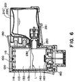
Figure 6 is a sectional drawing for depicting
the operation for supplying the ink jet head cartridge
illustrated in Figure 2, with ink.
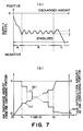
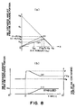
Figure 7 is a graph for depicting the state
of the ink during ink consumption, with reference to
Figure 6.
Figure 8 is a graph for depicting the effect
of the change in the internal pressure resulting from
the deformation of the internal bladder during the ink
consumption in the ink jet head cartridge shown in
Figure 6.
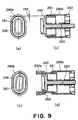
Figure 9 is a sectional drawing for depicting
the relationship between the valve body and valve plug
in the valve mechanism to which the present invention
is applicable.
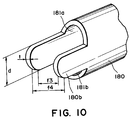
Figure 10 is a perspective view of an example
of the shape of the end portion of the joint pipe
which engages with the valve mechanism when the valve
mechanism is opened or closed, and to which the
present invention is applicable.
Figure 11 is a sectional drawing for
depicting an example of a valve mechanism, which is to
be compared with the valve mechanism in accordance
with the present invention.
Figure 12 is a sectional drawing for
depicting the state of twisting in the valve mechanism
illustrated in Figure 11.
Figure 13 is a sectional drawing for
depicting how the liquid outlet is sealed by the valve
mechanism illustrated in Figure 11.
Figure 14 is a sectional drawing for
depicting the valve mechanism in accordance with the
present invention.
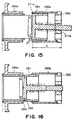
Figure 15 is a sectional drawing for
depicting the state of twisting in the valve mechanism
illustrated in Figure 14.
Figure 16 is a sectional drawing for
depicting how the liquid outlet is sealed by the valve
mechanism illustrated in Figure 14.
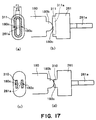
Figure 17 is a schematic drawing for
depicting how the valve plug of the valve mechanism
illustrated in Figure 14 engages with the end portion
of the joint pipe.
Figure 18 is a sectional drawing for
depicting the method for manufacturing an ink storing
container in accordance with the present invention.
Figure 19 is a sectional view of the ink
storing container illustrated in Figure 2, for
depicting an example of the internal structure of the
ink container.
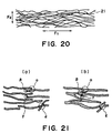
Figure 20 is a schematic drawing for
depicting the absorbent material in the negative
pressure controlling chamber shell illustrated in
Figure 2.
Figure 21 is also a schematic drawing for
depicting the absorbent material in the negative
pressure controlling chamber shell illustrated in
Figure 2.
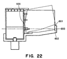
Figure 22 is a schematic drawing for
depicting the rotation of the ink container unit
illustrated in Figure 2, which is caused when the ink
container unit is installed or removed.
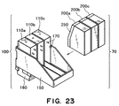
Figure 23 is a schematic perspective view of
an ink jet head cartridge compatible with the ink
container unit in accordance with the present
invention.
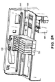
Figure 24 is a schematic perspective view of
a recording apparatus compatible with the ink jet head
cartridge in accordance with the present invention.
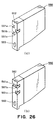
Figure 25 is a sectional view of the ink
container unit, for giving the measurements of the
structural components which constitute the joint
portion of the ink container unit in accordance with
the present invention.
Figure 26 is a sectional view of an ink
container unit of a comparison example.
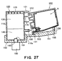
Figure 27 is a sectional view of an ink
container unit of a comparison example.
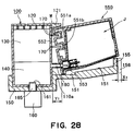
Figure 28 is a sectional view of an ink
container unit of a comparison example.
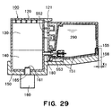
Figure 29 is a sectional view of an ink
container unit of a comparison example.
Figure 30 is a perspective view of an ink
container according to an another an embodiment of the
present invention.
Figure 31 is a sectional view illustrating an
operation of mounting the ink container unit to the
holder having the negative pressure control chamber
unit mounted thereto.
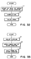
Figure 32 is a flow chart showing the
processes of mounting the ink container unit to the
holder.
Figure 33 is a flow chart showing processes
of dismounting ink container unit from the holder.
Figure 34 is a schematic perspective views of
examples of a joint pipe and a sealing projection
thereof.
Figure 35 is a schematic perspective views of
other examples of joint pipe and the sealing
projection thereof.
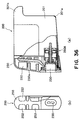
Figure 36 schematically shows another example
of an ink container unit to which the present
invention is applied.
Figure 37 is a schematic illustration of a
certain point in the mounting process of the ink
container unit to the holder.
Figure 38 is a schematic illustration of the
state in which the ink container unit has been mounted
to the holder.
Figure 39 is a schematic illustration of a
certain point of mounting process of the ink container
unit to the holder according to an aspect of the
present invention.
DESCRIPTION OF THE PREFERRED EMBODIMENTS
Hereinafter, the embodiments of the present
invention will be described with reference to the
appended drawings.
In the following description of the
embodiments of the present invention, "hardness" of a
capillary force generating portion means the
"hardness" of the capillary force generating portion
when the capillary force generating member is in the
liquid container. It is defined by the inclination of
the amount of resiliency of the capillary force
generating member relative to the amount of
deformation. As for the difference in hardness
between two capillary force generating members, a
capillary force generating member which is greater in
the inclination in the amount of resiliency relative
to the amount of deformation is considered to be
"harder capillary force generating member".
〈General Structure〉
Figure 1 is a perspective view of the ink jet
head cartridge in the first of the embodiments of the
present invention, and Figure 2 is a sectional view of
the same ink jet head cartridge.
In this embodiment, each of the structural
components of the ink jet head cartridge in accordance
with the present invention, and the relationship among
these components, will be described. Since the ink
jet head cartridge in this embodiment was structured
so that a number of innovative technologies, which
were developed during the making of the present
invention, could be applied to the ink jet cartridge
which was being invented, the innovative structures
will also be described as the overall description of
this ink jet head cartridge is given.
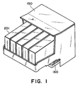
Referring to Figures 1 and 2, the ink jet
head cartridge in this embodiment comprises an ink jet
head unit 160, a holder 150, a negative pressure
controlling chamber unit 100, an ink container unit
200, and the like. The negative pressure controlling
chamber unit 100 is fixed to the inward side of the
holder 150. Below the negative pressure controlling
chamber unit 100, the ink jet head is attached to the
outward side of the bottom wall portion of the holder
150. Using screws or interlocking structures, for
ease of disassembly, to fix the negative pressure
controlling chamber unit 100 and ink jet head unit 160
to the holder 150 is desirable in terms of recycling,
and also is effective for reducing the cost increase
which is incurred by the structural modification or
the like. Further, since the various components are
different in the length of service life, the
aforementioned ease of disassembly is also desirable
because it makes it easier to replace only the
components which need to be replaced. It is obvious,
however, that they may be permanently connected to
each other by welding, thermal crimping, or the like.
The negative pressure controlling chamber unit 100
comprises: a negative pressure controlling chamber
shell 110, which is open at the top; a negative
pressure controlling chamber cover 120 which is
attached to the top portion of the negative pressure
controlling chamber shell 110 to cover the opening of
the negative pressure controlling chamber shell 110;
two pieces of absorbent material 130 and 140 which are
placed in the negative pressure controlling chamber
shell 110 to hold ink by impregnation. The absorbent
material pieces 130 and 140 are filled in vertical
layers in the negative pressure controlling chamber
shell 110, with the absorbent material piece 130 being
on top of the absorbent material piece 140, so that
when the ink jet head cartridge is in use, the
absorbent material pieces 130 and 140 remain in
contact with each other with no gap between them. The
capillary force generated by the absorbent material
piece 140, which is at the bottom, is greater than the
capillary force generated by the absorbent material
piece 130 which is at the top, and therefore, the
absorbent material piece 140 which is at the bottom is
greater in ink retainment. To the ink jet head unit
160, the ink within the negative pressure controlling
chamber unit 100 is supplied through an ink supply
tube 165.
The opening 131 of the ink supply tube 160,
on the absorbent material piece 140 side, is provided
with a filter 161, which is in contact with the
absorbent material piece 140, being under the pressure
from the elastic member. The ink container unit 200
is structured so that it can be removably mounted in
the holder 150. A joint pipe 180, which is a portion
of the negative pressure controlling chamber shell 110
and is located on the ink container unit 200 side, is
connected to the joint opening 230 of the ink
container unit 200 by being inserted thereinto. The
negative pressure controlling chamber unit 100 and ink
container unit 200 are structured so that the ink
within the ink container unit 200 is supplied into the
negative pressure controlling chamber unit 100 through
the joint portion between the joint pipe 180 and joint
opening 230. Above the joint pipe 180 of the negative
pressure controlling chamber shell 110, on the ink
container unit 200 side, there is an ID member 170 for
preventing the ink container unit 200 from being
incorrectly installed, which projects from the surface
of the holder 150, on the ink container unit 200 side.
The negative pressure controlling chamber
cover 120 is provided with an air vent 115 through
which the internal space of the negative pressure
controlling chamber shell 110 is connected to the
outside; more precisely, the absorbent material piece
130 filled in the negative pressure controlling
chamber shell 110 is exposed to the outside air.
Within the negative pressure controlling chamber shell
110 and adjacent to the air vent, there is a buffering
space 116, which comprises an empty space formed by a
plurality of ribs projecting inwardly from the inward
surface of the negative pressure controlling chamber
cover 120, on the absorbent material piece 130 side,
and a portion of the absorbent material piece 130, in
which no ink (liquid) is present.
On the inward side of the joint opening 230,
a valve mechanism is provided, which comprises a first
valve body (or frame) 260a, a second valve body 260b,
valve plug (or member) 261, a valve cover (or cap)
262, and a resilient member 263. The valve plug 261
is held within the second valve body 260b, being
allowed to slide within the second valve body 260b and
also being kept under the pressure generated toward
the first valve body 260a by the resilient member 263.
Thus, unless the joint pipe 180 is inserted through
the joint opening 230, the edge of the first valve
plug 261, on the first valve body 260a side, is kept
pressed against the first valve body 260a by the
pressure generated by the resilient member 263, and
therefore, the ink container unit 200 remains
airtightly sealed.
As the joint pipe 180 is inserted into the
ink container unit 200 through the joint opening 230,
the valve plug 261 is moved by the joint pipe 180 in
the direction to separate it from the first valve body
260a. As a result, the internal space of the joint
pipe 180 is connected to the internal space of the ink
container unit 200 through the opening provided in the
side wall of the second valve body 260b, breaking the
airtightness of the ink container unit 200.
Consequently, the ink container unit 200 begins to be
supplied into the negative pressure controlling
chamber unit 100 through the joint opening 230 and
joint pipe 180. In other words, as the valve on the
inward side of the joint opening 230 opens, the
internal space of the ink holding portion of the ink
container unit 200, which remained airtightly sealed,
becomes connected to the negative pressure controlling
chamber unit 100 only through the aforementioned
opening.
It should be noted here that fixing the ink
jet head unit 160 and negative pressure controlling
chamber unit 100 to the holder 150 with the use of
easily reversible means, such as screws, as is done in
this embodiment, is desirable because the two units
160 and 100 can be easily replaced as their service
lives end.
More specifically, in the case of the ink jet
head cartridge in this embodiment, the provision of an
ID member on each ink container makes it rare that an
ink container for containing one type of ink is
connected to a negative pressure controlling chamber
for an ink container for containing another type of
ink. Further, should the ID member provided on the
negative pressure controlling chamber unit 100 be
damaged, or should a user deliberately connect an ink
container to a wrong negative pressure controlling
chamber unit 100, all that is necessary is to replace
only the negative pressure control chamber unit 100 as
long as it is immediately after the incident.
Further, if the holder 150 is damaged by falling or
the like, it is possible to replace only the holder
150.
It is desirable that the points, at which the
ink container unit 200, negative pressure controlling
chamber unit 100, holder 150, and ink jet head unit
160, are interlocked to each other, are chosen to
prevent ink from leaking from any of these units when
they are disassembled from each other.
In this embodiment, the ink container unit
200 is held to the negative pressure controlling
chamber unit 100 by the ink container retaining
portion 155 of the holder 150. Therefore, it does not
occur that only the negative pressure controlling
chamber unit 100 becomes disengaged from the other
units, inclusive of the negative pressure controlling
chamber unit 100, interlocked among them. In other
words, the above components are structured so that
unless at least the ink container unit 200 is removed
from the holder 150, it is difficult to remove the
negative pressure controlling chamber unit 100 from
the holder 150. As described above, the negative
pressure controlling chamber unit 100 is structured so
that it can be easily removed only after the ink
container unit 200 is removed from the holder 150.
Therefore, there is no possibility that the ink
container unit 200 will inadvertently separate from
the negative pressure controlling chamber unit 100 and
ink leak from the joint portion.
The end portion of the ink supply tube 165 of
the ink jet head unit 160 is provided with the filter
161, and therefore, even after the negative pressure
controlling chamber unit 100 is removed, there is no
possibility that the ink within the ink jet head unit
160 will leak out. In addition, the negative pressure
controlling chamber unit 100 is provided with the
buffering space 116 (inclusive of the portions of the
absorbent material piece 130 and the portions of the
absorbent material piece 140, in which no ink is
present), and also, the negative pressure controlling
chamber unit 100 is designed so that when the attitude
of the negative pressure controlling chamber unit 100
is such an attitude that is assumed when the printer
is being used, the interface 113c between the two
absorbent material pieces 130 and 140, which are
different in the amount of the capillary force, is
positioned higher than the joint pipe 180 (preferably,
the capillary force generated at the interface 113c
and its adjacencies becomes greater than the capillary
force in the other portions of the absorbent material
pieces 130 and 140). Therefore, even if the
structural conglomeration comprising the holder 150,
negative pressure controlling chamber unit 100, and
ink container unit 200, changes in attitude, there is
very little possibility of ink leakage. Thus in this
embodiment, the portion of the ink jet head unit 160,
by which the ink jet head unit 160 is attached to the
holder 150, is located on the bottom side, that is,
the side where the electric terminals of the holder
150 are located, so that the ink jet head unit 160 can
be easily removed even when the ink container unit 200
is in the holder 150.
Depending upon the shape of the holder 150,
the negative pressure controlling chamber unit 100 or
ink jet head unit 160 may be integral with, that is,
inseparable from, the holder 150. As for a method for
integration, they may be integrally formed from the
beginning of manufacture, or may be separately formed,
and integrated thereafter by thermal crimping or the
like so that they become inseparable.
Referring to Figures 2, 3(a), and 3(b), the
ink container unit 200 comprises an ink storing or
accommodating container or reservoir 201, the valve
mechanism comprising the first and second valve bodies
260a and 260b, and the ID member 250. The ID member
250 is a member for preventing installation mistakes
which occur during the joining of ink container unit
200 to negative pressure controlling chamber unit 100.
The valve mechanism is a mechanism for
controlling the ink flow through the joint opening
230, and is opened, or closed, as it is engaged with,
or disengaged from, the joint pipe 180 of the negative
pressure controlling chamber unit 100, respectively.
The misalignment, or twisting, of the valve plug,
which tends to occur during the installation or
removal of the ink container unit 200, is prevented
with the provision of an innovative valve structure,
which will be described later, or the provision of an
ID member 170 and an ID member slots 252, which limit
the rotational range of the ink container unit 200.
〈Ink Container Unit〉
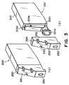
Figure 3 is a perspective drawing for
depicting the ink container unit 200 illustrated in
Figure 2. Figure 3, (a), is a perspective view of the
ink container unit 200 in the assembled form, and
Figure 3, (b), is a perspective view of the ink
container unit 200 in the disassembled form.
The front side of the ID member 250, that is,
the side which faces the negative pressure controlling
chamber unit 100, is slanted backward from the point
slightly above the supply outlet hole 253, forming a
slanted (or tapered) surface 251. More specifically,
the bottom end, that is, the supply outlet hole 253
side, of the slanted surface 251 is the front side,
and the top end, that is, the ink storing container
201 side, of the slanted surface 251 is the rear side.
The slanted surface 251 is provided with a plurality
of ID slots 252 (three in the case of Figure 3) for
preventing the wrong installation of the ink container
unit 200. Also in this embodiment, the ID member 250
is positioned on the front surface (surface with the
supply outlet), that is, the surface which faces the
negative pressure controlling chamber unit 100, of the
ink storing container 201.
The ink storing container 201 is a hollow
container in the form of an approximately polygonal
prism, and is enabled to generate negative pressure.
It comprises the external shell 210, or the outer
layer, and the internal bladder 220, or the inner layer
(Figure 2), which are separable from each other. The
internal bladder 220 is flexible, and is capable of
changing in shape as the ink held therein is drawn
out. Also, the internal bladder 220 is provided with a
pinch-off portion (welding seam portion) 221, at which
the internal bladder 220 is attached to the external
shell 210; the internal bladder 220 is supported by the
external shell 210. Adjacent to the pinch-off portion
221, the air vent 222 of the external shell 210 is
located, through which the outside air can be
introduced into the space between the internal bladder
220 and external shell 210.
Referring to Figure 19, the internal bladder
220 is a laminar bladder, having three layers different
in function: a liquid contact layer 220c, or the layer
which makes contact with the liquid; an elastic
modulus controlling layer 220b; and a gas barrier
layer 220a superior in blocking gas permeation. The
elastic modulus of the elastic modulus controlling
layer 220b remains virtually stable within the
temperature range in which the ink storing container
201 is used; in other words, the elastic modulus of
the internal bladder 220 is kept virtually stable by the
elastic modulus controlling layer 220b within the
temperature range in which the ink storing container
201 is used. The middle and outermost layers of the
internal bladder 220 may be switched in position; the
elastic modulus controlling layer 220b and gas barrier
layer 220a may be the outermost layer and middle
layer, respectively.
Structuring the internal bladder 220 as
described above makes it possible for the internal
bladder 220 to synergistically display each of the
individual functions of the ink-resistant layer 220c,
elastic modulus controlling layer 220b, and gas
barrier layer 220a, while using only a small number of
layers. Thus, the temperature sensitive properties,
for example, the elastic modulus, of the internal
bladder 220 is less likely to be affected by the
temperature change. In other words, the elastic
modulus of the internal bladder 220 can be kept within
the proper range for controlling the negative pressure
in the ink storing container 201, within the
temperature range in which the ink storing container
201 is used. Therefore, the internal bladder 220 is
enabled to function as the buffer for the ink within
the ink storing container 201 and negative pressure
controlling chamber shell 110 (details will be given
later). Consequently, it becomes possible to reduce
the size of the buffering chamber, that is, the
portion of the internal space of the negative pressure
controlling chamber shell 110, which is not filled
with ink absorbing material, inclusive of the portion
of the absorbent material piece 130, in which ink is
not present, and the portion of the absorbent material
piece 140, in which ink is not present. Therefore, it
is possible to reduce the size of the negative
pressure controlling chamber unit 100, which in turn
makes it possible to realize an ink jet head cartridge
70 which is superior in operational efficiency.
In this embodiment, polypropylene is used as
the material for the liquid contact layer 220c, or the
innermost layer, of the internal bladder 220, and cyclic
olefin copolymer is used as the material for the
elastic modulus controlling layer 220b, or the middle
layer. As for the material for the gas barrier layer
220a, or the outermost layer, EVOH (ethylene-vinyl
acetate copolymer: EVA resin) is used. It is desired
that functional adhesive resin is mixed in the elastic
modulus controlling layer 220b, because such a mixture
eliminates the need for an adhesive layer between the
adjacent functional layers, reducing the thickness of
the wall of the internal bladder 220.
As for the material for the external shell
210, polypropylene is used, as it is used for the
material for the innermost layer of the internal bladder
220. Polypropylene is also used as the material for
the first valve body 260a.
The ID member 250 is provided with a
plurality of ID member slots 252, which are arranged
at the left and right edges of the front surface,
corresponding to the plurality of ID members 170 for
the prevention of the incorrect installation of the
ink container unit 200.
The installation mistake preventing function
is provided by the installation mistake prevention
mechanism, which comprises the plurality of ID members
170 provided on the negative pressure controlling
chamber unit 100 side, and the ID member slots 252
provided by the ID member 250 corresponding to the
positions of the ID members 170. Therefore, a large
number of ink container unit installation areas can be
made identifiable by changing the shapes and positions
of the ID members 170 and ID member slots 252.
The ID member slots 252 of the ID member 250,
and the joint opening 230 of the first valve body
260a, are located in the front surface of the ink
container unit 200, that is, the front side in terms
of the direction in which the ink container unit 200
is installed or removed. They are parts of the ID
member 250 and first valve body 260a, respectively.
The ink storing container 201 is formed by
blow molding, and the ID member 250 and first valve
body 260a are formed by injection molding. Giving the
ink container unit 200 a three piece structure makes
it possible to precisely form the valve body and ID
member slots 252.
If the ID member slots 252 are directly
formed as the portions of the wall of the ink storing
container 201 by blow molding, the shape of the
internal space of the ink containing portion becomes
complicated, affecting the separation of the internal
bladder 100 wall, or the inner layer of the ink storing
container 201, which sometimes affects the negative
pressure generated by the ink container unit 200.
Separately forming the ID member 250 and ink container
portion 201, and then attaching the ID member 250 to
the ink containing portion 202, as the ink container
unit 200 in this embodiment is structured, eliminates
the aforementioned effect, making it possible to
generate and maintain stable negative pressure in the
ink storing container 201.
The first valve body 260a is attached to at
least the internal bladder 220 of the ink storing
container 201. More specifically, the first valve
body 260a is attached by welding the exposed portion
221a, that is, the ink outlet portion of the ink
storing container 201, to the surface of the joint
opening 230 corresponding to the exposed portion 221a.
Since both the external shell 210 and the innermost
layer of the internal bladder 220 are formed of the same
material, that is, polypropylene, the first valve body
260a can be welded to the external shell 210 also at
the periphery of the joint opening 230.
The above described welding method increases
accuracy in the positional relationship among the
mutually welded components, while perfectly sealing
the supply outlet portion of the ink storing container
201, and therefore, preventing ink leakage or the like
which tends to occur at the seal portion between the
first valve body 260a and the ink storing container
201 when the ink container unit 200 is installed,
removed, or the like motion. When the first valve
body 260a is attached to the ink storing container 201
by welding as in the case of the ink container unit
200 in this embodiment, it is desired for the sake of
better sealing that the material for the internal
bladder 220 layer, which provides the bonding surface,
is the same as the material for the first valve body
260a.
As for the attachment of the ID member 250 to
the external shell 210, in order to firmly join them,
the shell surface which faces the sealing surface 102
of the first valve body 260a, which is bonded to the
ink containing portion 210, is joined, by
interlocking, to the click portions 250a of the ID
member 250, which is located at the bottom portion of
the ID member 250, and the engagement portion 210a of
the external shell 210, which is located on the side
walls of the external shell 210, are interlocked with
the other click portions 250a of the ID member 250.
Regarding the word "interlocking", the
mutually interlockable portions of these components
are structured in the form of a projection or an
indentation which fit with each other in an easily
disengageable manner. Interlocking the ID member 250
with the ink storing container 201 allows both
components to move slightly against each other.
Therefore, the force generated by the contact between
the ID members 170 and the ID member slots 252 during
the installation or removal of these components can be
absorbed to prevent the ink container unit 200 and
negative pressure controlling chamber unit 100 from
being damaged during the installation or removal of
these components.
Also, interlocking the ID member 250 with the
ink storing container 201 using only a limited number
of the portions of the possible contact area makes it
easier to disassemble the ink container unit 200,
which is beneficial in consideration of its recycling.
Providing indentations as the engagement portions 210a
in the side walls of the external shell 210 makes the
structure of the ink storing container 201 simpler to
form by blow molding, and therefore, makes the mold
pieces simpler. In addition, it makes it easier to
control the film thickness.
Also regarding the joining of the ID member
250 to the external shell 210, the ID member 250 is
joined to the external shell 210 after the first valve
body 260a is welded to the external shell 210. Since
the click portions 250a are interlocked with the
engagement portions 210a, in the state in which the
peripheral portion of the first valve body 260a is
tightly surrounded at the periphery of the joint
opening 230 by the inward surface of the ID member
250, the joint portion becomes stronger against the
force which applies to the joint portion when the ink
container unit 200 is installed or removed.
The shape of the ink storing container 201 is
such that the portion to be covered by the ID member
250 is recessed, and the supply outlet portion
protrudes. However, the protruding shape of the front
side of the ink container unit 200 is hidden from view
by the fixation of the ID member 250 to the ink
storing container 201. Further, the welding seam
between the first valve body 260a and ink storing
portion 201 is covered by the ID member 250, being
thereby protected. The relationship between the
engagement portions 210a of the external shell 210 and
the corresponding click portions 250a of the ID member
250, with regard to which side is projecting and which
side is recessed, may be reversal to their
relationship in this embodiment.
As described before, it is assured by the
joint pipe 180 and valve mechanism that ink does not
leak when the ink container unit 200 is installed. In
this embodiment, a rubber joint portion 280 is fitted
around the base portion of the joint pipe 180 of the
negative pressure controlling chamber unit 100 to deal
with unpredictable ink leakage. The rubber joint
portion 280 seals between the ID member 250 and ink
container unit 200, improving the degree of
airtightness between the negative pressure controlling
chamber unit 100 and ink container unit 200. When
removing the ink container unit 200, this airtightness
could function as resistance. However, in the case of
this embodiment, the ID member 250 and ink storing
container 201 are interlocked with the presence of a
small amount of gap, allowing air to be introduced
between the rubber joint portion 280 and ID member
250, and therefore, although ink is prevented from
leaking, the force necessary to be applied for
removing the ink container unit 200 is not as large as
it otherwise would be, because of the provision of the
rubber joint portion 280.
Further, the positions of the ink storing
container 201 and IC member 250 can be controlled in
terms of both the lengthwise and widthwise directions.
The method for joining the ink storing container 201
with the ID member 250 does not need to be limited to
a method such as the one described above; different
joining points and different joining means may be
employed.
Referring to Figures 2 and 22, the bottom
wall of the ink storing container 201 is slanted
upward toward the rear, and is engaged with the ink
containing unit engagement portion 155 of the holder
150, by the bottom rear portion, that is, the portion
opposite to the ink outlet side. The holder 150 and
ink container unit 200 are structured so that when
removing the ink container unit 200 from the holder
150, the portion of the ink storing container 201,
which is in contact with the ink containing portion
engagement portion 155, can be moved upward. In other
words, when the ink container unit 200 is removed, the
ink container unit 200 is rotated by a small angle.
In this embodiment, the center of this rotation
virtually coincides with the supply outlet opening
(joint opening 230). However, strictly speaking, the
position of this rotational center shifts as will be
described later. In the case of the above described
structural arrangement, which requires the ink
container unit 200 to be rotationally moved to be
disengaged from the holder 150, the greater the
difference by which the distance (A) from the
rotational center of the ink container unit 200 to the
bottom rear corner of the ink container unit 200
corresponding to the ink containing unit engagement
portion 155, is longer than the distance (B) from the
same rotational center to the ink containing unit
engagement portion 155, the more frictionally do the
bottom rear corner of the ink container unit 200 and
the image containing unit engagement portion 155 rub
against each other, requiring a substantially greater
amount of force to install the ink container unit 200,
which sometimes causes problems such as deformation of
the contact areas on both the ink container unit 200
side and holder 150 side.
Slanting the bottom wall of the ink storing
container 201 so that the position of the ink
containing portion engagement portion 155 side of the
bottom wall of the ink storing container 201 becomes
higher than that of the front end of the ink storing
container 201, as in this embodiment, prevents the ink
container unit 200 from heavily rubbing against the
holder 150 during its rotational motion. Therefore,
the ink container unit 200 can be smoothly installed
or removed.
In this embodiment, the joint opening 230 of
the ink jet head cartridge is located in the bottom
portion of the sidewall of the ink storing container
201, on the negative pressure controlling chamber unit
side, and the bottom portion of another wall of the
ink storing container 201, that is, the wall opposite
to the wall in which the joint opening 230 is located
is engaged with the ink container engagement portion
155; in other words, the bottom rear portion of the
ink storing container 201 is engaged with the ink
storing container engagement portion 155. Also, the
ink storing container engagement portion 155 extends
upward from the bottom wall of the holder 150, so that
the position of the top portion of the ink storing
container engagement portion 155 becomes approximately
the same as the position 603 of the horizontal center
line of the joint opening 230, in terms of the
vertical direction. With this arrangement, it is
assured that the horizontal movement of the joint
opening 230 is regulated by the ink storing container
engagement portion 155 to keep the joint opening 230
correctly connected with the joint pipe 180. In this
embodiment, in order to assure that the joint opening
230 is correctly connected with the joint pipe 180
during the installation of the ink container unit 200,
the top end of the ink storing container engagement
portion 155 is positioned at approximately the same
height as the upper portion of the joint opening 230,
and the ink container unit 200 is removably installed
into the holder 150 by rotating the ink container unit
200 about a portion of the front surface of the ink
container unit 200 on the joint opening 230 side.
During the removal of the ink container unit 200, the
portion of the ink container unit 200 which remains in
contact with the negative pressure controlling chamber
unit 100 functions as the rotational center for the
ink container unit 200. As is evident from the above
description, making the bottom wall of the ink storing
container 201 of the ink jet head cartridge slanted
upward toward its bottom rear portion as described
above reduces the difference between the distance from
the rotational center 600 to the top end of the ink
storing container engagement portion, and the distance
from the rotational center 600 to the bottom end of
the ink storing container engagement portion.
Therefore, the portions of the ink container unit 200,
which make contact with the holder 150, and the
portions of the holder 150, which make contact with
the ink container unit 200, are prevented from
strongly rubbing against each other. Therefore, the
ink container unit 200 can be smoothly installed or
removed.
By shaping the ink storing container 201 and
holder 150 as described above, it is possible to keep
relatively small the size of the portion of the bottom
rear portion of the ink storing container 201, which
rubs against the ink storing container engagement
portion 155 during the installation or removal of the
ink container unit 200, and the size of the portion of
the ink storing container engagement portion 155,
which rubs against the bottom rear portion of the ink
storing container 201, even if the joint opening 230
is enlarged to deliver ink at a greater volumetric
rate. Therefore, the ink container unit 200 is
prevented from uselessly rubbing against the ink
storing container engagement portion 155 during the
installation of the ink container unit 200 into the
holder 150, and yet, it is assured that the ink
container unit 200 remains firmly attached to the
holder 150.
Next, referring to Figure 22, the movement of
the ink container unit 200 during its installation or
removal will be described in detail. When the
distance from the rotational center 600, about which
the ink container unit 200 rotates during its
installation or removal, to the bottom end 602 of the
ink container engagement portion, is greater than the
distance from the same rotational center 600 to the
top end 601 of the ink container engagement portion,
by an excessive margin, the force necessary for the
installation or removal of the ink container unit 200
is excessively large, and therefore, it sometimes
occurs that the top end 601 of the ink container
engagement portion is shaved, or the ink storing
container 201 deforms.
Thus, the difference between the distance
from the rotational center 600, about which the ink
container unit 200 rotates during its installation or
removal, to the bottom end 602 of the ink container
engagement portion, and the distance from the same
rotational center 600 to the top end 601 of the ink
container engagement portion, should be as small as
possible within a range in which the ink container
unit 200 is retained in the holder 150 with a proper
degree of firmness while affording smooth installation
or removal of the ink container unit 200.
If the position of the rotational center 600
of the ink container unit 200 is made lower than the
position of the center of the joint opening 230, the
distance from the rotational center 600, about which
the ink container unit 200 rotates during its
installation or removal, to the top end 601 of the ink
container engagement portion, becomes longer than the
distance from the same rotational center 600 to the
bottom end 602 of the ink container engagement
portion. Therefore, it becomes difficult to
accurately hold the ink storing container 201 at a
point which is at the same height as the center of the
joint opening 230. Thus, in order to accurately
position the vertical center of the joint portion 230,
it is desired that the position of the rotational
center 600 of the ink container unit 200 is higher
than the position of the vertical center of the joint
opening 230.
If the structure of the ink container unit
200 is changed so that the position of the rotational
center 600 of ink container unit 200 becomes higher
than the position 603 of the vertical center of the
joint opening 230, the portion of the ink container
unit 200, which corresponds to the ink container
engagement portion 155, becomes thicker, requiring the
height of the ink storing container engagement portion
155 to be increased. As a result, there will be an
increased possibility that the ink container unit 200
and holder 150 will be damaged. Thus, it is desired,
in view of the smoothness of the installation or
removal of the ink container unit 200, that the
position of the rotational center 600 of the ink
container unit 200 is close to the vertical center of
the joint opening 230. The height of the ink
container engagement portion 155 of the holder 150 has
to be properly determined based only on the ease of
the installation or removal of the ink container unit
200. However, if the height of the ink container
engagement portion 155 is increased so that the
position of its top end becomes higher than that of
the rotational center 600, the length by which the ink
container unit 200 contacts the ink container
engagement portion 155 of the holder 150 becomes
greater, which in turn increases the sizes of the
portions on both sides, which rub against each other.
Therefore, in consideration of the deterioration of
the ink container unit 200 and holder 150, the height
of the ink container engagement portion 155 is such
that the position of its top end is lower than that of
the rotational center 600.
In the ink jet head cartridge in this
embodiment, the elastic force for keeping the position
of the ink storing container 201 fixed in terms of the
horizontal direction is a combination of the force
generated by the resilient member 263 for pressing the
valve plug 261, and the force generated by the
resiliency of the rubber joint portion 280 (Figure 4).
However, the configuration for generating the above
resiliency does not need to be limited to the one in
this embodiment; the bottom rear end, or the
engagement portion, of the ink storing container 201,
the surface of the ink storing container engagement
portion 155, on the ink storing container side, the
negative pressure controlling chamber unit 100, or the
like, may be provided with an elastic force generating
means for keeping the position of the ink storing
container 201 fixed in terms of the horizontal
direction. When the ink storing container is in
connection with the negative pressure controlling
chamber, the rubber joint portion 280 remains
compressed between the walls of the negative pressure
controlling chamber and ink storing container,
assuring that the joint portion (peripheral portion of
the joint pipe) is airtightly sealed (it is not
necessary to maintain perfect airtightness as long as
the size of the area exposed to the outside air can be
minimized). Also, the rubber joint portion 280 plays
an auxiliary role in coordination with a sealing
projection, which will be described later.
Next, the internal structure of the negative
pressure controlling chamber unit 100 will be
described.
In the negative pressure controlling chamber
unit 100, the absorbent material pieces 130 and 140
are disposed in layers as members for generating
negative pressure, the former being on top of the
latter. Thus, the absorbent material piece 130 is
exposed to the outside air through the air vent 115,
whereas the absorbent material piece 140 is airtightly
in contact with the absorbent material piece 130, at
its top surface, and also is airtightly in contact
with the filter 161 at its bottom surface. The
position of the interface between the absorbent
material pieces 130 and 140 is such that when the ink
jet head cartridge is placed in the same attitude as
the ink jet head cartridge is in use, it is higher
than the position of the uppermost portion of the
joint pipe 180 as a liquid passage.
The absorbent material pieces 130 and 140 are
formed of fibrous material, and are held in the
negative pressure controlling chamber shell 110, so
that in the state in which the ink jet head cartridge
70 has been properly installed into the printer, its
fibers extend in substantially the same, or primary,
direction, being angled (preferably, in the virtually
horizontal direction as they are in this embodiment)
relative to the vertical direction.
As for the material for the absorbent
material pieces 130 and 140, the fibers of which are
arranged in virtually the same direction, short
(approximately 60 mm) crimped mixed strands of fiber
formed of thermoplastic resin (polypropylene,
polyethylene, and the like) are used. In production,
a wad of such strands is put through a carding machine
to parallel the strands, is heated (heating
temperature is desired to be set higher than the
melting point of polyethylene, which is relatively
low, and lower than the molding point of
polypropylene, which is relatively high), and then, is
cut to a desired length. The fiber strands of the
absorbent material pieces in this embodiment are
greater in the degree of alignment in the surface
portion than in the center portion, and therefore, the
capillary force generated by the absorbent members is
greater in the surface portion than in the center
portion. However, the surfaces of the absorbent
material pieces are not as flat as a mirror surface.
In other words, they have a certain amount of
unevenness which results mainly when the slivers are
bundled; they are three dimensional, and the
intersections of the slivers, at which they are welded
to each other, are exposed from the surfaces of the
absorbent material pieces. Thus, in strict terms, the
interface 113c between the absorbent material pieces
130 and 140 is an interface between the two uneven
surfaces, allowing ink to flow by a proper amount in
the horizontal direction along the interface 113c and
also through the adjacencies of the interface 113c.
In other words, it does not occur that ink is allowed
to flow far more freely along the interface 113c than
through its adjacencies, and therefore, an ink path is
formed through the gaps between the walls of the
negative pressure controlling chamber shell 110 and
absorbent material pieces 130 and 140, and along the
interface 113c. Thus, by making a structural
arrangement so that the interface 113c between the
absorbent material pieces 130 and 140 is above the
uppermost portion of the joint pipe 180, preferably,
above and close to the uppermost portion of the joint
pipe 180 as in this embodiment, when the ink jet head
cartridge is positioned in the same attitude as it is
when in use, the position of the interface between the
ink and gas in the absorbent material pieces 130 and
140 during the gas-liquid exchange, which will be
described later, can be made to coincide with the
position of the interface 113c. As a result, the
negative pressure in the head portion during the ink
supplying operation can be stabilized.
Referring to Figure 20, if attention is paid
to the directionality of the strands of fiber in any
portion of the fibrous absorbent material piece, it is
evident that plural strands of fiber are extended in a
direction F1, or the longitudinal direction of the
absorbent material piece, in which the strands have
been arranged by a carding machine. In terms of the
direction F2 perpendicular to the direction F1, the
strands are connected to each other by being fused to
each other at their intersections during the
aforementioned heating process. Therefore, the fiber
strands in the absorbent material pieces 130 and 140
are not likely to be separated from each other when
the absorbent material pieces 130 or 140 is stretched
in the direction F1. However, the fiber strands which
are not likely to separate when pulled in the
direction F1 can be easily separated at the
intersections at which they have been fused with each
other if the absorbent material piece 130 or 140 is
stretched in the direction F2.
Since the absorbent material pieces 130 and
140 formed of the fiber strands possess the above
described directionality in terms of the strand
arrangement, the primary fiber direction, that is, the
fiber direction F1 is different from the fiber
direction F2 perpendicular to the direction F1 in
terms of how ink flows through the absorbent pieces,
and also in terms of how ink is statically held
therein.
To look at the internal structures of the
absorbent material pieces 130 and 140 in more detail,
the state of a wad of short strands of fiber crimped
and carded as shown in Figure 21, (a), changes to the
state shown in Figure 21, (b), as it is heated. More
specifically, in a region α in which plural short
strands of crimped fiber extend in an overlapping
manner, more or less in the same direction, the fiber
strands are likely to be fused to each other at their
intersections, becoming connected as shown in Figure
21, (b) and therefore, difficult to separate in the
direction F1 in Figure 20. On the other hand, the
21tips of the short strands of crimped fiber (tips β
and γ in Figure 21, (a)) are likely to three-dimensionally
fuse with other strands like the tip β
in Figure 21, (b), or remain unattached like the tip
γ in Figure 21, (b). However, all the strands do
extend in the same direction. In other words, some
strands extend in the nonconforming direction and
intersect with the adjacent strands (region ε in
Figure 21, (a)) even before heat is applied, and as
heat is applied, they fuse with the adjacent strands
in the position they are in, (region ε in Figure 21,
(b)). Thus, compared to a conventional absorbent
piece constituted of a bundle of unidirectionally
arranged strands of fiber, the absorbent members in
this embodiment are also far more difficult to split
in the direction F2.
Further, in this embodiment, the absorbent
pieces 130 and 140 are disposed so that the primary
fiber strand direction F1 in the absorbent pieces 130
and 140 becomes nearly parallel to the horizontal
direction and the line which connects the joint
portion and the ink supply outlet. Therefore, after
the connection of ink storing container 201, the gas-liquid
interface L (interface between ink and gas) in
the absorbent piece 140 becomes nearly horizontal,
that is, virtually parallel to the primary fiber
strand direction F1, remaining virtually horizontal
even if ambient changes occur, and as the ambience
settles, the gas-liquid interface L returns to its
original position. Thus, the position of the gas-liquid
interface in terms of the gravitational
direction is not affected by the number of the cycles
of the ambient change.
Thus, even when the ink container unit 200 is
replaced with a fresh one because the ink storing
container 201 has run out of ink, the gas-liquid
interface remains virtually horizontal, and therefore,
the size of the buffering space 116 does not decrease
no matter how many times the ink container unit 200 is
replaced.
All that is necessary in order to keep the
position of the gas-liquid interface stable in spite
of the ambient changes during the gas-liquid exchange
is that the fiber strands in the region immediately
above the joint between the negative pressure
controlling chamber unit 100 and ink container unit
200 (in the case of this embodiment, above the
position of the joint pipe 180), preferably inclusive
of the adjacencies of the region immediately above the
joint, are extended in the more or less horizontal
direction. From a different viewpoint, all that is
necessary is that the above described region is
between the ink delivery interface and the joint
between the negative pressure controlling chamber unit
100 and ink container unit 200. From another
viewpoint, all that is necessary is that the position
of this region is above the gas-liquid interface while
gas-liquid exchange is occurring. To analyze the
latter viewpoint with reference to the functionality
of this region in which the fiber strands posses the
above described directionality, this region
contributes to keeping horizontal the gas-liquid
interface in the absorbent piece 140 while the liquid
is supplied through the gas-liquid exchange; in other
words, the region contributes to regulate the changes
which occur in the vertical direction in the absorbent
material piece 140 in response to the movement of the
liquid into the absorbent material piece 140 from the
ink storing container 201.
The provision of the above described region
or layer in the absorbent material piece 140 makes it
possible to reduce the unevenness of the gas-liquid
interface L in terms of the gravity direction.
Further, it is desired that the fiber strands in the
aforementioned region or layer be arranged so that
they appear to extend in parallel in the
aforementioned primary direction even when they are
seen from the direction perpendicular to the
horizontal direction of the absorbent material piece
140, because such an arrangement enhances the effect
of the directional arrangement of the fiber strands in
the more or less parallel manner in the primary
direction.
Regarding the direction in which the fiber
strands are extended, theoretically, when the general
direction in which the fiber strands are extended is
angled relative to the vertical direction, the above
described effect can be provided, although the amount
of effect may be small if the angle is small. In
practical terms, as long as the above described angle
was in a range of ±30° relative to the horizontal
direction, the effect was clearly confirmed. Thus,
the term "more or less" in the phrase "more or less
horizontal" in this specification includes the above
range.
In this embodiment, the fiber strands in the
absorbent material piece 140 are extended more or less
in parallel in the primary direction also in the
region below and adjacent to the joint portion,
preventing therefore the gas-liquid interface L from
becoming unpredictably uneven in the region below the
uppermost portion of the joint portion, as shown in
Figure 6, during the gas-liquid exchange. Therefore,
it does not occur that the ink jet head cartridge
fails to be supplied with a proper amount of ink due
to the interruption of ink delivery.
More specifically, during the gas-liquid
exchange, the outside air introduced through the air
vent 115 reaches the gas-liquid interface L. As it
reaches the interface L, it is dispersed along the
fiber strands. As a result, the interface L is kept
more or less horizontal during the gas-liquid
exchange; it remains stable, assuring that the ink is
supplied while a stable amount of negative pressure is
maintained. Since the primary direction in which the
fiber strands are extended in this embodiment is more
or less horizontal, the ink is consumed through the
gas-liquid exchange in such a manner that the top
surface of the ink remains more or less horizontal,
making it possible to provide an ink supplying system
which minimizes the amount of the ink left unused,
even the amount of the ink left unused in the negative
pressure controlling chamber shell 110. Therefore, in
the case of an ink supplying system such as the system
in this embodiment which allows the ink containing
unit 200, in which liquid is directly stored, to be
replaced, it is easier to provide the absorbent
material pieces 130 and 140 with regions in which ink
is not retained. In other words, it is easier to
increase the buffering space ratio, to provide an ink
supplying system which is substantially more resistant
to the ambient changes than a conventional ink
supplying system.
When the ink jet head cartridge in this
embodiment is the type of cartridge mountable in a
serial type printer, it is mounted on a carriage which
is shuttled. As this carriage is shuttled, the ink in
the ink jet head cartridge is subjected to the force
generated by the movement of the carriage, more
specifically, the component of the force in the
direction of the carriage movement. In order to
minimize the adverse effects of this force upon the
ink delivery from the ink container unit 200 to ink
jet head unit 160, the direction of the fiber strands
in the absorbent material pieces 130 and 140 and the
direction in which the ink container unit 200 and
negative pressure controlling chamber unit 100 are
connected, are desired to coincide with the direction
of the line which connects the joint opening 230 of
the ink container unit 200 and the ink outlet 131 of
the negative pressure controlling chamber shell 110.
〈Operation for Installing Ink Containing Unit〉
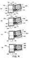
Next, referring to Figure 4, the operation
for installing the ink containing unit 200 into the
integral combination of the negative pressure
controlling chamber unit 100 and holder 150 will be
described.
Figure 4 is a sectional drawing for depicting
the operation for installing the ink container unit
200 into the holder 150 to which the negative pressure
controlling chamber unit 100 has been attached. The
ink container unit 200 is installed into the holder
150 by being moved in the direction F as well as the
direction G, while being slightly rotated by being
guided by the unillustrated lateral guides, the bottom
wall of the holder 150, the guiding portions 121 with
which the negative pressure controlling chamber cover
120 of the negative pressure controlling chamber unit
100, the ink container engagement portion 155, that
is, the rear end portion of the holder 150.
More specifically, the installation of the
ink container unit 200 occurs as follows. First, the
ink container unit 200 is moved to a point indicated
in Figure 4, (a), that is, the point at which the
slanted surface 251 of the ink container unit 200
comes into contact with the ID members 170 with which
the negative pressure controlling chamber unit 100 is
provided to prevent the wrong installation of the ink
container unit 200. The holder 150 and ink container
unit 200 are structured so that at the point in time
when the above described contact occurs, the joint
pipe 180 has yet to enter the joint opening 230. If a
wrong ink container unit 200 is inserted, the slanted
surface 251 of the wrong ink container unit 200
collides with the ID members 170 at this point in
time, preventing the wrong ink container unit 200 from
being inserted further. With this structural
arrangement of the ink jet head cartridge 70, the
joint opening 230 of the wrong ink container unit 200
does not make contact with joint pipe 180. Therefore,
the problems which occur at the joint portion as a
wrong ink container unit 200 is inserted, for example,
the mixture of inks with different color, and the
solidification of ink in the absorbent material pieces
130 and 140 (anions in one type of ink react with
cations in another type of ink), which might cause the
negative pressure controlling chamber unit 100 to stop
functioning, can be prevented, and therefore, it will
never occurs that the head and ink containing portion
of an apparatus, the ink containing portions of which
are replaceable, needs to be replaced due to the
occurrence of such problems. Further, since the ID
portions of the ID member 250 are provided on the
slanted surface of the ID member, the plurality of ID
members 170 can be almost simultaneously fitted into
the correspondent ID slots to confirm that a correct
ink container unit 200 is being inserted; a reliable
installation mistake prevention mechanism is provided.
In the next step, the ink container unit 200
is moved toward the negative pressure controlling
chamber unit 100 so that the ID members 170 and joint
pipe 180 are inserted into the ID member slots 252 and
joint opening 230, respectively, at the same time, as
shown in Figure 4, (b), until the leading end of the
ink container unit 200 reaches the negative pressure
controlling chamber unit 100 as shown in Figure 4,
(c). Next, the ink container unit 200 is rotationally
moved in the direction indicated by an arrow mark G.
During the rotational movement of the ink container
unit 200, the tip of the joint pipe 180 comes into
contact with the valve plug 261 and pushes it. At a
result, the valve mechanism opens, allowing the
internal space of the ink container unit 200 to be
connected to the internal space of the negative
pressure controlling chamber unit 100, in other words,
enabling the ink 300 in the ink container unit 200 to
be supplied into the negative pressure controlling
chamber unit 100. The detailed description of the
opening or closing movement of this valve mechanism
will be given later.
Next, the ink container unit 200 is further
rotated in the direction of the arrow mark G, until
the ink container unit 200 settles as shown in Figure
2. As a result, the bottom rear end portion of the
ink container unit 200 becomes engaged with the ink
container engagement portion 155 of the holder 150; in
other words, the ink container unit 200 is correctly
placed in the predetermined space for the ink
container unit 200. During this second rotational
movement of the ink container unit 200, the ID members
170 slightly come out of the ID member slots 252. The
rearward force for correctly retaining the ink
container unit 200 in the ink container unit space is
generated toward the ink container engagement portion
155 of the holder 150 by the resilient member 263 in
the ink container unit 200 and the rubber joint
portion 280 fitted around the joint pipe 180.
Since the ID member slots 252 are provided in
the slanted front wall of the ink container unit 200
which is rotationally installed or removed, and also,
the bottom wall of the ink container unit 200 is
slanted, it is possible to minimize the space
necessary to assure that the ink container unit 200 is
installed or removed without making mistakes or mixing
inks of different color.
As soon as the ink container unit 200 is
connected with the negative pressure controlling
chamber unit 100 as described above, the ink moves
until the internal pressure of the negative pressure
controlling chamber unit 100 and the internal pressure
of the ink storing container 201 equalize to realize
the equilibrium state illustrated in Figure 4, (d), in
which the internal pressure of the joint pipe 180 and
joint opening 230 remains negative (this state is
called initial state of usage ).
At this time, the ink movement which results
in the aforementioned equilibrium will be described in
detail.
The valve mechanism provided in the joint
opening 230 of the ink storing container 201 is opened
by the installation of the ink container unit 200.
Even after the opening of the valve mechanism, the ink
holding portion of the ink storing container 201
remains virtually sealed except for the small passage
through the joint pipe 230. As a result, the ink in
the ink storing container 201 flows into the joint
opening 230, forming an ink path between the internal
space of the ink storing container 201 and the
absorbent material piece 140 in the negative pressure
controlling chamber unit 100. As the ink path is
formed, the ink begins to move from the ink storing
container 201 into the absorbent material piece 140
because of the capillary force of the absorbent
material piece 140. As a result, the ink-gas
interface in the absorbent material piece 140 rises.
Meanwhile, the internal bladder 220 begins to deform,
starting from the center portion of the largest wall,
in the direction to reduce the internal volume.
The external shell 210 functions to impede
the displacement of the corner portions of the
internal bladder 220, countering the deformation of the
internal bladder 220 caused by the ink consumption. In
other words, it works to preserve the pre-installation
state of the internal bladder 220 (initial state
illustrated in Figure 4, (a) - (c)). Therefore, the
internal bladder 220 produces and maintains a proper
amount of negative pressure correspondent to the
amount of deformation, without suddenly deforming.
Since the space between the external shell 210 and
internal bladder 220 is connected to the outside through
the air vent 222, air is introduced into the space
between the external shell 210 and internal bladder 220
in response to the aforementioned deformation.
Even if air is present in the joint opening
230 and joint pipe 180, this air easily moves into the
internal bladder 220 because the internal bladder 220
deforms as the ink in the internal bladder 220 is drawn
out through the ink path formed as the ink from the
ink storing container 201 comes into contact with the
absorbent material piece 140.
The ink movement continues until the amount
of the static negative pressure in the joint opening
230 of the ink storing container 201 becomes the same
as the amount of the static negative pressure in the
joint pipe 180 of the negative pressure controlling
chamber unit 100.
As described above, the ink movement from the
ink storing container 201 into the negative pressure
controlling chamber unit 100, which is triggered by
the connection of the ink storing container 201 with
the negative pressure controlling chamber unit 100,
continues without the introduction of gas into the ink
storing container 201 through the absorbent material
pieces 130 and 140. What is important to this process
is to configure the ink storing container 201 and
negative pressure controlling chamber unit 100
according to the type of a liquid jet recording means
to which the ink container unit 200 is connected, so
that the static negative pressures in the ink storing
container 201 and negative pressure controlling
chamber unit 100 reach proper values for preventing
ink from leaking from the liquid jet recording means
such as the ink jet head unit 160 which is connected
to the ink outlet of the negative pressure controlling
chamber unit 100.
The amount of the ink held in the absorbent
material piece 130 prior to the connection varies.
Therefore, some regions in the absorbent piece 140
remain unfilled with ink. These regions can be used
as the buffering regions.
On the other hand, sometimes the internal
pressures of the joint pipe 180 and joint opening 230
are caused to become positive due to the
aforementioned variation. When there is such a
possibility, a small amount of ink may be flowed out
by performing a recovery operation with a suction-based
recovering means, with which the main assembly
of a liquid jet recording apparatus is provided, to
deal with the possibility. This recovery means will
be described later.
As described before, the ink container unit
200 in this embodiment is installed into the holder
150 through a movement which involves a slight
rotation; it is inserted at an angle while resting on
the ink container engagement portion 155 of the holder
150, by its bottom wall, and after the bottom rear end
of the ink container unit 200 goes over the ink
container engagement portion 155, it is pushed
downward into the holder 150. When the ink container
unit 200 is removed from the holder 150, the above
described steps are reversely taken. The valve
mechanism with which the ink container unit 200 is
provided is opened or closed as the ink container unit
200 is installed or removed, respectively.
〈Opening or Closing of Valve Mechanism〉
Hereinafter, referring to Figure 5, (a) -
(e), the operation for opening or closing the valve
mechanism will be described. Figure 5, (a), shows the
states of the joint pipe 180 and its adjacencies, and
the joint opening 230 and its adjacencies, immediately
before the joint pipe 180 is inserted into the joint
opening 230, but after the ink container unit 200 was
inserted into the holder 150 at an angle so that the
joint opening 230 tilts slightly downward.
The joint pipe 180 is provided with a sealing
projection 180a, which is integrally formed with the
joint pipe 180, and extends on the peripheral surface
of the joint pipe 180, encircling the peripheral
surface of the joint pipe 180. It is also provided
with a valve activation projection 180b, which forms
the tip of the joint pipe 180. The sealing projection
180a comes into contact with the joint sealing surface
260 of the joint opening 230 as the joint pipe 180 is
inserted into the joint opening 230. The sealing
projection 180a extends around the joint pipe 180 at
an angle so that the distance from the uppermost
portion of the sealing projection 180a to the joint
sealing surface 260 becomes greater than the distance
from the bottommost portion of the sealing projection
180a to the joint sealing surface 260.
When the ink container unit 200 is installed
or removed, the joint sealing surface rubs against the
sealing projection 180a, as will be described later.
Therefore, the material for the sealing projection
180a is desired to be such material that is slippery
and yet capable of sealing between itself and an
object it contacts. The configuration of the
resilient member 263 for keeping the valve plug 26a
pressed upon or toward the first valve body 260a does
not need to be limited to a particular one; a springy
member such as a coil spring or a plate spring, or a
resilient member formed of rubber or the like, may be
employed. However, in consideration of recycling, a
resilient member formed of resin is preferable.
In the state depicted in Figure 5, (a), the
valve activation projection 180b is yet to make
contact with the valve plug 261, and the seal portion
of the valve plug 261, provided at the periphery of
the joint pipe 180, on the joint pipe side, is in
contact with the seal portion of the first valve body
260a, with the valve plug 261 being under the pressure
from the resilient member 263. Therefore, the ink
container unit 200 remains airtightly sealed.
As the ink container unit 200 is inserted
further into the holder 150, the joint portion is
sealed at the sealing surface 260 of the joint opening
230 by the sealing projection 180a. During this
sealing process, first, the bottom side of the sealing
projection 180a comes into contact with the joint
sealing surface 260, gradually increasing the size of
the contact area toward the top side of the sealing
projection 180a while sliding against the joint
sealing surface 260. Eventually, the top side of the
sealing projecting 180a comes into contact with the
joint sealing surface 260 as shown in Figure 5, (c).
As a result, the sealing projection 180a makes contact
with the joint sealing surface 260, by the entire
peripheral surface, sealing the joint opening 230.
In the state illustrated in Figure 5, (c),
the valve activation projection 180b is not in contact
with the valve plug 261, and therefore, the valve
mechanism is not open. In other words, before the
valve mechanism is opened, the gap between the joint
pipe 180 and joint opening 230 is sealed, preventing
ink from leaking from the joint opening 230 during the
installation of the ink container unit 200.
Further, as described above, the joint
opening 230 is gradually sealed from the bottom side
of the joint sealing surface 260. Therefore, until
the joint opening 230 is sealed by the sealing
projection 180a, the air in the joint opening 230 is
discharged through the gap between the sealing
projection 180a and joint sealing surface 260. As the
air in the joint opening 230 is discharged as
described above, the amount of the air remaining in
the joint opening 230 after the joint opening 230 is
sealed is minimized, preventing the air in the joint
opening 230 from being excessively compressed by the
invasion of the joint pipe 180 into the joint opening
230, in other words, preventing the internal pressure
of the joint opening 230 from rising excessively.
Thus, it is possible to prevent the phenomenon that
before the ink container unit 200 is completely
installed into the holder 150, the valve mechanism is
inadvertently opened by the increased internal
pressure of the joint opening 230, and ink leaks into
the joint opening 230.
As the ink container unit 200 is further
inserted, the valve activation projection 180b pushes
the valve plug 261 against the resiliency of the
resilient member 263, with the joint opening 230
remaining sealed by the sealing projection 180a, as
shown in Figure 5, (d). As a result, the internal
space of the ink storing container 201 becomes
connected to the internal space of the joint opening
230 through the opening 260c of the second valve body
26. Consequently, the air in the joint opening 230 is
allowed to be drawn into the ink container unit 200
through the opening 260c, and the ink in the ink
container unit 200 is supplied into the negative
pressure controlling chamber shell 110 (Figure 2).
As the air in the joint opening 230 is drawn
into the ink container unit 200 as described above,
the negative pressure in the internal bladder 220
(Figure 2) is reduced, for example, when an ink
container unit 200 the ink in which has been partially
consumed is re-installed. Therefore, the balance in
the internal negative pressure between the negative
pressure controlling chamber shell 110 and internal
bladder 220 is improved, preventing the ink from being
inefficiently supplied into the negative pressure
controlling chamber shell 110 after the re-installation
of the ink container unit 200.
After the completion of the above described
steps, the ink container unit 200 is pushed down onto
the bottom wall of the holder 150 to finish installing
the ink container unit 200 into the holder 150 as
shown in Figure 5, (e). As a result, the joint
opening 230 is perfectly connected to the joint pipe
180, realizing the aforementioned state which assures
that gas-liquid exchange occurs flawlessly.
In this embodiment, the opening 260c of the
second valve body 260b is located adjacent to the
valve body seal portion 264 and on the bottom side of
the ink container unit 200. According to the
configuration of this opening 260, during the opening
of the valve mechanism, more specifically, immediately
after the valve plug 261 is moved toward the valve
cover 262 by being pushed by the valve activation
projection 180b, the ink in the ink container unit 200
begins to be supplied into the negative pressure
controlling chamber unit 100. Also, it is possible to
minimize the amount of the ink which remains in the
ink container unit 200 when the ink container unit 200
needs to be discarded because the ink therein can no
longer be drawn out.
Also in this embodiment, elastomer is used as
the material for the joint sealing surface 260, that
is, the seal portion, of the first valve body 260a.
With the use of elastomer as the material for the
joint sealing surface 260, it is assured that because
of the resilience of the elastomer, the joint between
the joint sealing surface 260 and the sealing
projection 180a of the joint pipe 180 is perfectly
sealed, and also, the joint between the seal portion
of the first valve body 260a and the correspondent
seal portion of the valve plug 261 is perfectly
sealed. In addition, by providing the elastomer with
an amount of resiliency exceeding the minimum amount
of resiliency necessary to assure that the joint
between the first valve body 260a and joint pipe 180
is perfectly sealed (for example, by increasing the
thickness of the elastomer layer), the flexibility of
elastomer compensates for the effects of the
misalignment, twisting, and/or rubbing, which occur at
the contact point between the joint pipe 180 and valve
plug 261 during the serial scanning movement of an ink
jet head cartridge; it is doubly assured that the
joint remains perfectly sealed. The joint sealing
surface 260, the material for which is elastomer, can
be integrally formed with the first valve body 260a,
making it possible to provide the above described
effects without increasing the number of components.
Elastomer usage does not need to be limited to the
above described structure; elastomer may also be used
as the material for the sealing projection 180a of the
joint pipe 180, the seal portion of the valve plug
261, and the like.
On the other hand, when the ink container
unit 200 is removed from the holder 150, the above
described installation steps occur in reverse,
unsealing the joint opening 230, and allowing the
valve mechanism to close.
In other words, as the ink container unit 200
is pulled in the direction to remove it from the
holder 150, while gradually rotating the ink container
unit 200 in the direction opposite to the installation
direction, first, the valve plug 261 moves forward due
to the resiliency of the resilient member 263, and
presses on the seal portion of the first valve body
260a by its sealing surface to close the joint opening
230.
Then, as the ink container unit 200 is pulled
out of the holder 150, the gap between the wall of the
joint opening 230 and the joint pipe 180, which
remained sealed by the sealing projection 180a, is
unsealed. Since this gap is unsealed after the
closing of the valve mechanism, it does not occur that
ink is wastefully released into the joint opening 230.
In addition, since the sealing projection
180a is disposed at an angle as described before, the
unsealing of the joint opening 230 occurs from the top
side of the sealing projection 180a. Before the joint
opening 230 is unsealed, ink remains in the joint
opening 230 and joint pipe 180. However, it is at the
top side where the unsealing starts. In other words,
the bottom side remains sealed, preventing ink from
leaking out of the joint opening 230. Further, the
internal pressure of the joint opening 230 and joint
pipe 180 is negative, and therefore, as the joint is
unsealed from the top side of the sealing projection
180a, the outside air enters into the joint opening
230, causing the ink remaining in the joint opening
230 and 180 to be drawn into the negative pressure
controlling chamber shell 110.
By causing the joint opening 230 to be
unsealed starting from the top side of the sealing
projection 180a to make the ink remaining in the joint
opening 230 move into the negative pressure
controlling chamber shell 110, it is possible to
prevent ink from leaking from the joint opening 230 as
the ink container unit 200 is removed from the holder
150.
As described above, according to the
structure of the junction between the ink container
unit 200 and negative pressure controlling chamber
shell 110, the joint opening 230 is sealed before the
valve mechanism of the ink container unit 200 is
activated, and therefore, ink is prevented from
inadvertently leaking from the joint opening 230.
Further, since a time lag is provided between the top
and bottom sides of the sealing projection 180a in
terms of the sealing and unsealing timing, the valve
plug 261 is prevented from inadvertently moving during
the connection, and the ink remaining in the joint
opening 230 is prevented from leaking during the
connection and during the removal.
Also in this embodiment, the valve plug 261
is disposed in the joint opening 230, at a point
deeper inside the joint opening 230, away from the
outside opening of the joint opening 230, and the
movement of the valve plug 261 is controlled by the
valve activation projection 180b provided at the
projecting end of the joint pipe 180. Therefore, a
user is not required to touch the valve plug 261,
being prevented from being contaminated by the ink
adhering to the valve plug 261.
〈Relationship between Engagement or Disengagement of
Joint Portion, and ID〉
Next, referring to Figures 4 and 5, the
relationship between the engagement or disengagement
of the joint portion, and ID will be described.
Figures 4 and 5 are drawings for depicting the steps
for installing the ink container unit 200 into the
holder 150, wherein Figures 4, (a), (b), and (c), and
Figure 5, (a), (b), and (c), correspondingly represent
the same steps. Figures 4 and 5 show in detail the
portion related to ID, and the joint portion,
respectively.
In the first step, the ink container unit 200
is inserted up to the position illustrated in Figure
4, (a) and Figure 5, (a), at which the plurality of ID
members 170 for preventing the ink container unit
installation error make contact with the slanted wall
251 of the ink container. The holder 150 and ink
container unit 200 are structured so that at this
point in time, the joint opening 230 and joint pipe
180 do not make contact. If a wrong ink container
unit 200 is inserted, the slanted surface 251 of the
wrong ink container unit 200 collides with the ID
members 170 at this point in time, preventing the
wrong ink container unit 200 from being inserted
further. With this structural arrangement, the joint
opening 230 of the wrong ink container unit 200 never
makes contact with joint pipe 180. Therefore, the
problems which occur at the joint portion as a wrong
ink container unit 200 is inserted, for example, the
mixture of inks with different color, ink
solidification, production of incomplete images, and
breaking down of the apparatus, can be prevented, and
therefore, it never occurs that the head and ink
containing portion of an apparatus, the ink containing
portions of which are replaceable, will be replaced
due to the occurrence of such problems.
If the inserted ink container unit 200 is a
correct one, the positions of the ID members 170 match
the positions of the ID member slots 252. Therefore,
the ink container unit 200 is inserted a little deeper
toward the negative pressure controlling chamber unit
100 to a position shown in Figure 4, (b). At this
position, the joint sealing surface 260 of the joint
opening 230 of the ink container unit 200 has come
into contact with the bottom side of the sealing
projection 180a of the joint pipe 180.
Thereafter, the both sides are completely
joined through the steps described before, providing a
passage between the internal space of the ink
container unit 200 and the internal space of the
negative pressure controlling chamber unit 100.
In the above described embodiment, the
sealing projection 180a is an integral part of the
joint pipe 180. However, the two components may be
separately formed. In such a case, the sealing
projection 180a is fitted around the joint pipe 180,
being loosely held by a projection formed on the
peripheral surface of the joint pipe 180, or a groove
provided in the peripheral surface of the joint pipe
180, so that the sealing projection 180a is allowed to
move on the peripheral surface of the joint pipe 180.
However, the joint portion is structured so that
within the moving range of the independent sealing
projection 180a, the valve action controlling
projection 180b does not make contact with the valve
plug 261 until the sealing projection 180a comes into
contact with the joint sealing surface 260.
In the above description of this embodiment,
it is described that as the ink container unit 200 is
further inserted, the bottom side of the sealing
projection 180a comes into contact with the joint
sealing surface 260, and the sealing projection 180a
slides on the joint sealing surface 260, gradually
expanding the contact range between the sealing
projection 180a and the joint sealing surface 260,
upward toward the top side of the sealing projection
180a, until the top end of the sealing projection 180a
finally comes into contact with the joint sealing
surface 260. However, the installation process may be
such that, first, the top side of the sealing
projection 180a comes into contact with the joint
sealing surface 260, and as the ink container unit 200
is further inserted, the sealing projection 180a
slides on the joint sealing surface 260, gradually
expanding the contact range between the sealing
projection 180a and the joint sealing surface 260,
downward toward the bottom end of the sealing
projection 180a, until the bottom end of the sealing
projection 180a finally makes contact with the joint
sealing surface 260a. Further, the contact between
the sealing projection 180a and joint sealing surface
260 may occur simultaneously at both the top and
bottom sides. During the above process, if the air
present between the joint pipe 180 and valve plug 261
opens the valve mechanism by pushing the valve plug
261 inward of the joint opening 230, the ink 300
within the ink storing container 201 does not leak
outward, because the joint opening 230 has been
completely sealed at the joint between the sealing
projection 180a and joint sealing surface 260. In
other words, the essential point of this invention is
that the valve mechanism is opened only after the
joint between the joint pipe 180 and joint opening 230
is completely sealed. According to this structure, it
does not occur that the ink 300 within the ink
container unit 200 leaks out during the installation
of the ink container unit 200. In addition, the air
pushed into the joint opening 230 enters the ink
container unit 200, and pushes out the ink 300 in the
ink storing container 201 into the joint opening 230,
contributing to smoothly supplying ink from the ink
storing container 201 into the absorbent material
piece 140.
〈Ink Supplying Operation〉
Next, referring to Figure 6, the ink
supplying operation of the ink jet head cartridge
illustrated in Figure 2 will be described. Figure 6
is a sectional drawing for describing the ink
supplying operation of the ink jet head cartridge
illustrated in Figure 2.
By dividing the absorbent material in the
negative pressure controlling chamber unit 100 into a
plurality of pieces, and positioning the interface
between the divided pieces of the absorbent material
so that the interface will be positioned above the top
end of the joint pipe 180 when the ink jet head
cartridge is disposed in the attitude in which it is
used, as described above, it becomes possible to
consume the ink within the absorbent piece 140, or the
bottom piece, after the ink within the absorbent
material piece 130, or the top piece, if ink is
present in both the absorbent material pieces 130 and
140 of the ink jet head cartridge illustrated in
Figure 2. Further, if the position of the gas-liquid
interface L changes due to the ambient changes, ink
seeps into the absorbent material piece 130 after
filling up, first, the absorbent material piece 140
and the adjacencies of the interface 113c between the
absorbent material pieces 130 and 140. Therefore, it
is assured that buffering zone in addition to the
buffering space 116 is provided in the negative
pressure controlling chamber unit 100. Making the
strength of the capillary force of the absorbent
material piece 140 higher compared to that of the
absorbent material piece 130 assures that the ink in
the absorbent material piece 130 is consumed when the
ink jet head cartridge is operating.
Further, in this embodiment, the absorbent
material piece 130 remains pressed toward the
absorbent material piece 140 by the ribs of the
negative pressure controlling chamber cover 120, and
therefore, the absorbent material piece 130 is kept in
contact with the absorbent material piece 140, forming
the interface 113c. The compression ratios of the
absorbent material pieces 130 and 140 are higher
adjacent to the interface 113c than those in the other
portions, and therefore, the capillary force is
greater adjacent to the interface 113c than that in
the other portions. More specifically, representing
the capillary force of the absorbent material piece
140, the capillary force of the absorbent material
piece 130, and the capillary force of the area
adjacent to the interface 113c between the absorbent
material pieces 130 and 140, with P1, P2, and PS,
correspondingly, their relationship is: P2 < P1 < PS.
Providing the area adjacent to the interface 113c
between the absorbent material pieces 130 and 140 with
such capillary force that is stronger than that in the
other areas assures that the strength of the capillary
force in the area adjacent to the interface 113c
exceeds the strength necessary to meet the above
described requirement, even if the ranges of the
strengths of the P1 and P2 overlap with each other
because of the unevenness of the absorbent material
pieces 130 and 140 in terms of their density, or
compression. Therefore, it is assured that the above
described effects will be provided. Further,
positioning the joint pipe 180 below, and adjacent to,
the interface 113c between the absorbent material
pieces 130 and 140 assures that the gas-liquid
interface remains at this position, and therefore, is
desired.
Accordingly, next, the method for forming the
interface 113c, in this embodiment, will be described.
In this embodiment, olefinic fiber (2 denier) with a
capillary force of -110 mmAq (P1 = -110 mmAq) is used
as the material for the absorbent material piece 140
as a capillary force generating member. The hardness
of the absorbent material pieces 130 and 140 is 0.69
kgf/mm. The method for measuring their hardness is
such that, first, the resilient force generated as a
pushing rod with a diameter of 15 mm is pushed against
the absorbent material placed in the negative pressure
controlling chamber shell 110 is measured, and then,
the hardness is obtained from the relationship between
the distance the pushing rod was inserted, and the
measured amount of the resilient force correspondent
to the distance. On the other hand, the same material
as that for the absorbent material piece 140, that is,
olefinic fiber, is used as the material for the
absorbent material piece 130. However, compared to
the absorbent material piece 140, the absorbent
material piece 130 is made weaker in capillary force
(P2 = -80 mmAq), and is made larger in the fiber
diameter (6 denier), making it higher in rigidity at
1.88 kgf/mm.
By making the absorbent material piece 130,
which is weaker in capillary force than the absorbent
material piece 140, greater in hardness than the
absorbent material piece 140, placing them in
combination, and in contact, with each other, and
keeping them pressed against each other, causes the
absorbent material piece 140 to be kept more
compressed than the absorbent material piece 130,
adjacent to the interface 113c between the absorbent
material pieces 130 and 140. Therefore, the
aforementioned relationship in capillary force (P2 <
P1 < PS) is established adjacent to the interface
113c, and also it is assured that the difference
between the P2 and PS remains always greater than the
difference between the P2 and P1.
〈Ink Consumption〉
Next, referring to Figures 6 - 8, the
outlines of the ink consuming process will be
described from the time when the ink container unit
200 has been installed into the holder 150 and has
become connected to the negative pressure controlling
chamber unit 100, to the time when the ink in the ink
storing container 201 begins to be consumed. Figure 7
is a drawing for describing the state of the ink
during the ink consumption described with reference to
Figure 6, and Figure 8 is a graph for depicting the
effects of the deformation of the internal bladder 220
upon the prevention of the internal pressure change in
the ink container unit 200.
First, as the ink storing container 201 is
connected to the negative pressure controlling chamber
unit 100, the ink in the ink storing container 201
moves into the negative pressure controlling chamber
unit 100 until the internal pressure of the negative
pressure controlling chamber unit 100 becomes equal to
the internal pressure of the ink storing container
201, readying the ink jet head cartridge for a
recording operation. Next, as the ink begins to be
consumed by the ink jet head unit 160, both the ink in
the internal bladder 220 and the ink in the absorbent
material piece 140 are consumed, maintaining such a
balance that the value of the static negative pressure
generated by the internal bladder 220 and absorbent
material piece 140 increases (first state: range A in
Figure 7, (a)). In this state, when ink is in the
absorbent material piece 130, the ink in the absorbent
material piece 130 is also consumed. Figure 7, (a) is
a graph for describing one of the examples of the rate
at which the negative pressure in the ink delivery
tube 165 varies. In Figure 7, (a), the axis of
abscissa represents the rate at which the ink is drawn
out of the negative pressure controlling chamber shell
110 through the ink delivery tube 160, and the axis of
ordinates represents the value of the negative
pressure (static negative pressure) in the ink
delivery tube 160.
Next, gas is drawn into the internal bladder
220, allowing ink to be consumed, that is, drawn out,
through gas-liquid exchange while the absorbent
material pieces 130 and 140 keep the position of the
gas-liquid interface L at about the same level, and
keep the internal negative pressure substantially
constant (second state: range B in Figure 7, (a)).
Then, the ink remaining in the capillary pressure
generating member holding chamber 110 is consumed
(range C in Figure 7, (a)).
As described above, the ink jet head
cartridge in this embodiment goes through the stage
(first stage) in which the ink in the internal bladder
220 is used without the introduction of the outside
air into the internal bladder 220. Therefore, the only
requirement to be considered regarding the internal
volume of the ink storing container 201 is the amount
of the air introduced into the internal bladder 220
during the connection. Therefore, the ink jet head
cartridge in this embodiment has merit in that it can
compensate for the ambient changes, for example,
temperature change, even if the requirement regarding
the internal volume of the ink storing container 201
is relaxed.
Further, in whichever period among the
aforementioned periods A, B, and C, in Figure 7, (a),
the ink storing container 201 is replaced, it is
assured that the proper amount of negative pressure is
generated, and therefore, ink is reliably supplied.
In other words, in the case of the ink jet head
cartridge in this embodiment, the ink in the ink
storing container 201 can be almost entirely consumed.
In addition, air may be present in the joint pipe 180
and/or joint opening 230 when the ink container unit
200 is replaced, and the ink storing container 201 can
be replaced regardless of the amounts of the ink
retained in the absorbent material pieces 130 and 140.
Therefore, it is possible to provide an ink jet head
cartridge which allows the ink storing container 201
to be replaced without relying on an ink remainder
detection mechanism; in other words, the ink jet head
cartridge in this embodiment does not need to be
provided with an ink remainder detection mechanism.
At this time, the aforementioned ink
consumption sequence will be described from a
different viewpoint, referring to Figure 7, (b).
Figure 7, (b) is a graph for describing the
above described ink consumption sequence. In Figure
7, (b), the axis of abscissas represents the elapsed
time, and the axis of ordinates represents the
cumulative amount of the ink drawn out of the ink
storing container, and the cumulative amount of the
air drawn into the internal bladder 220. It is assumed
that the rate at which the ink jet head unit 160 is
provided with ink remains constant throughout the
elapsed time.
The ink consumption sequence will be
described from the angles of the cumulative amount of
the ink drawn out of the ink containing portion, and
the cumulative amount of the air drawn into the
internal bladder 220, shown in Figure 7, (b). In Figure
7, (b), the cumulative amount of the ink drawn out of
the internal bladder 220 is represented by a solid line
(1), and the cumulative amount of the air drawn into
the ink containing portion is represented by a solid
line (2). A period from a time t0 to t1 corresponds
to the period A, or the period before the gas-liquid
exchange begins, in Figure 7, (a). In this period A,
the ink from the absorbent material piece 140 and
internal bladder 220 is drawn out of the head while
balance is maintained between the absorbent material
piece 140 and 220, as described above.
Next, the period from time t1 to time t2
corresponds to the gas-liquid exchange period (period
B) in Figure 7, (b). In this period B, the gas-liquid
exchange continues according to the negative pressure
balance, as described above. As air is introduced
into the internal bladder 220 (which corresponds to the
stepped portions of the solid line (2)), as indicated
by the solid line (1) in Figure 7, (b), ink is drawn
out of the internal bladder 220. During this process,
it does not occur that ink is always drawn out of the
internal bladder 220 by an amount equal to the amount of
the introduced air. For example, sometimes, ink is
drawn out of the internal bladder 220 a certain amount
of time after the air introduction, by an amount
equivalent to the amount of the introduced air. As is
evident from Figure 7, (b), the occurrence of this
kind of reaction, or the timing lag, characterizes the
ink jet head cartridge in this embodiment in
comparison to an ink jet head cartridge which does not
have an internal ink bladder (220), and the ink
containing portion of which does not deform. As
described above, this process is repeated during the
gas-liquid exchange period. As the ink in the
internal bladder 220 continues to be drawn out, the
relationship between the amounts of the air and ink in
the internal bladder 220 reverses at a certain point in
time.
The period after the time t2 corresponds to
the period (range C) after the gas-liquid exchange
period in Figure 7, (a). In this range C, the
internal pressure of the internal bladder 220 becomes
substantially the same as the atmospheric pressure as
stated before. As the internal pressure of the
internal bladder 220 gradually changes toward the
atmospheric pressure, the initial state (pre-usage
state) is gradually restored by the resiliency of the
internal bladder 220. However, because of the so-called
buckling, it does not occur that the state of the
internal bladder 220 is completely restored to its
initial state. Therefore the final amount Vc of the
air drawn into the internal bladder 220 is smaller than
the initial internal volume of the internal bladder 220
(V > Vc). Even in the state within the range C, the
ink in the internal bladder 220 can be completely
consumed.
As described above, the structure of the ink
jet head cartridge in this embodiment is characterized
in that the pressure fluctuation (amplitude γ in
Figure 7, (a)) which occurs during the gas-liquid
exchange in the ink jet head cartridge in this
embodiment is greater compared to that in an ink jet
head cartridge which employs a conventional ink
container system in which gas-liquid exchange occurs.
The reason for this characteristic is that
before the gas-liquid exchange begins, the internal
bladder 220 is deformed, and kept deformed, by the
drawing of the ink from inside the internal bladder 220.
Therefore, the resiliency of the internal bladder
material continuously generates such force that works
in the direction to move the wall of the internal
bladder 220 outward. As a result, the amount of the air
which enters the internal bladder 220 to reduce the
internal pressure difference between the absorbent
material piece 140 and internal bladder 220 during the
gas-liquid exchange often exceeds the proper amount,
as described, increasing the amount of the ink drawing
out of the internal bladder 220 into the external shell
210. On the contrary, if the ink container unit 200
is structured so that the wall of the ink containing
portion does not deform as does the wall of the
internal bladder 220, ink is immediately drawn out into
the negative pressure controlling chamber unit 100 as
soon as a certain amount of air enters the ink
containing portion.
For example, in 100 % duty mode (solid mode),
a large amount of ink is ejected all at once from the
ink jet head unit 160, causing ink to be rapidly drawn
out of the negative pressure controlling chamber unit
100 and ink storing container 201. However, in the
case of the ink jet head cartridge in this embodiment,
the amount of the ink drawn out through gas-liquid
exchange is relative large, improving the reliability,
that is, eliminating the concern regarding the
interruption of ink flow.
Also, according to the structure of the ink
jet head cartridge in this embodiment, ink is drawn
out with the internal bladder 220 remaining deformed
inward, providing thereby an additional benefit in
that the structure offers a higher degree of buffering
effect against the vibration of the carriage, ambient
changes, and the like.
As described above, according to the
structure of the ink jet head cartridge in this
embodiment, the slight changes in the negative
pressure can be eased by the internal bladder 220, and
even when air is present in the internal bladder 220,
for example, during the second stage in the ink
delivery, the ambient changes such as temperature
change can be compensated for by a method different
from the conventional methods.
Next, referring to Figure 8, a mechanism for
assuring that even when the ambient condition of the
ink jet head cartridge illustrated in Figure 2
changes, the liquid within the unit remains stable
will be described. In the following description, the
absorbent material pieces 130 and 140 may be called a
capillary force generating member.
As the air in the internal bladder 220 expands
due to decrease in the atmospheric pressure and/or
increase in the temperature, the walls or the like
portions of the internal bladder 220, and the liquid
surface in the internal bladder 220, are subjected to
pressure. As a result, not only does the internal
volume of the internal bladder 220 increase, but also a
portion of the ink in internal bladder 220 flows out
into the negative pressure controlling chamber shell
110 from the internal bladder 220 through the joint pipe
180. However, since the internal volume of the
internal bladder 220 increases, the amount of the ink
that flows out into the absorbent material piece 140
in the case of this embodiment is substantially
smaller compared to a case in which the ink storage
portion is undeformable.
As described above, the aforementioned
changes in the atmospheric pressure ease the negative
pressure in the internal bladder 220 and increase the
internal volume of the internal bladder 220. Therefore,
initially, the amount of the ink which flows out into
the negative pressure controlling chamber shell
through the joint opening 230 and joint pipe 180 as
the atmospheric pressure suddenly changes is
substantially affected by the resistive force
generated by the internal bladder wall as the inward
deformation of the wall portion of the internal bladder
220 is eased, and by the resistive force for moving
the ink so that the ink is absorbed by the capillary
force generating member.
In particular, in the case of the structure
in this embodiment, the flow resistance of the
capillary force generating members (absorbent material
pieces 130 and 140) is greater than the resistance of
the internal bladder 220 against the restoration of the
original state. Therefore, as the air expands,
initially, the internal volume of the internal bladder
220 increases. Then, as the amount of the air
expansion exceeds the maximum amount of the increase
in the internal volume of the internal bladder 220
afforded by the internal bladder 220, ink begins to
flows from within the internal bladder 220 toward the
negative pressure controlling chamber shell 110
through the joint opening 230 and joint pipe 180. In
other words, the wall of the internal bladder 220
functions as the buffer against the ambient changes,
and therefore, the ink movement in the capillary force
generating member calms down, stabilizing the negative
pressure adjacent to the ink delivery hole 165.
Also according to this embodiment, the ink
which flows out into the negative pressure controlling
chamber shell 110 is retained by the capillary force
generating members. In the aforementioned situation,
the amount of the ink in the negative pressure
controlling chamber shell 110 increases temporarily,
causing the gas-liquid interface to rise, and
therefore, in comparison to when the internal pressure
is stable, the internal pressure temporarily becomes
slightly positive, as it is initially. However, the
effect of this slightly positive internal pressure
upon the characteristics of a liquid ejection
recording means such as the ink jet head unit 160, in
terms of ejection, creates no practical problem. As
the atmospheric pressure returns to the normal level
(base unit of atmospheric pressure), or the
temperature returns to the original level, the ink
which leaked out into the negative pressure
controlling chamber shell 110 and has been retained in
the capillary force generating members, returns to the
internal bladder 220, and the internal bladder 220
restores its original internal volume.
Next, the basic action in the stable
condition restored under such atmospheric pressure
that has changed after the initial operation will be
described.
What characterizes this state is the amount
of the ink drawn out of the internal bladder 220, as
well as that the position of the interface between the
ink retained in the capillary force generating member,
and the gas, changes to compensate for the fluctuation
of the negative pressure resulting from the
fluctuation of the internal volume of the internal
bladder 220 itself. Regarding the relationship between
the amount of the ink absorbed by the capillary force
generating member and the ink storing container 201,
all that is necessary from the viewpoint of preventing
ink from leaking from the air vent or the like during
the aforementioned decrease in the atmospheric
pressure and temperature change, is to determine the
maximum amount of the ink to be absorbed by the
negative pressure controlling chamber shell 110 and
the amount of the ink to be retained in the negative
pressure controlling chamber shell 110 while the ink
is supplied from the ink storing container 201, in
consideration of the amount of the ink which flows out
of the ink storing container 201 under the worst
conditions, and then, to give the negative pressure
controlling chamber shell 110 an internal volume
sufficient for holding the capillary force generating
members, the sizes of which match the aforementioned
amount of ink under the worst conditions, and the
maximum amount of the ink to be absorbed.
In Figure 8, (a), the initial volume of the
internal space (volume of the air) of the internal
bladder 220 before the decrease in the atmospheric
pressure, in a case in which the internal bladder 220
does not deform at all in response to the expansion of
the air, is represented by the axis of abscissas (X),
and the amount of the ink which flowed out as the
atmospheric pressure decreased to a value of P (0 < P<
1) is represented by the axis of ordinates, and their
relationship is depicted by a dotted line (1).
The amount of the ink which flows out of the
internal bladder 220 under the worst conditions may be
estimated based on the following assumption. For
example, a situation in which the amount of the ink
which flows out of the internal bladder 220 becomes the
maximum when the lowest level to which the value of
the atmospheric pressure decreases is 0.7, is when the
volume of the ink remaining in the internal bladder 220
equals 30 % of the volumetric capacity VB of the
internal bladder 220. Therefore, presuming that the ink
below the bottom end of the wall of the internal bladder
220 is also absorbed by the capillary force generating
members in the negative pressure controlling chamber
shell 110, it may be expected that the entirety of the
ink remaining in the internal bladder 220 (equals in
volume to 30 % of the volumetric capacity VB) leaks
out.
On the contrary, in this embodiment, the
internal bladder 220 deforms in response to the
expansion of the air. In other words, compared to the
internal volume of the internal bladder 220 before the
expansion, the internal volume of the internal bladder
220 is greater after the expansion, and the ink level
in the negative pressure controlling chamber shell 110
changes to compensate for the fluctuation of the
negative pressure in the internal bladder 220. Under
the stable condition, the ink level in the negative
pressure controlling chamber shell 110 changes to
compensate for the decrease in the negative pressure
in the capillary force generating members, in
comparison to the negative pressure in the capillary
force generating members before the change in the
atmospheric pressure, caused by the ink from the
internal bladder 220. In other words, the amount of the
ink which flows out decreases in proportion to the
amount of the expansion of the internal bladder 220, as
depicted by a solid line (2). As is evident from the
dotted line (1) and solid line (2), the amount of the
ink which flows out of the internal bladder 220 may be
estimated to be smaller compared to that in the case
in which the internal bladder 220 does not deform at all
in response to the expansion of the air. The above
described phenomenon similarly occurs in the case of
the change in the temperature of the ink container,
except that even if the temperature increases
approximately 50 degrees, the amount of the ink
outflow is smaller than the aforementioned amount of
the ink outflow in response to the atmospheric
pressure decrease.
As described above, the ink container in
accordance with the present invention can compensate
for the expansion of the air in the ink storing
container 201 caused by the ambient changes not only
because of the buffering effect provided by the
negative pressure controlling chamber shell 110, but
also because of the buffering effect provided by the
ink storing container 201 which is enabled to increase
in its volumetric capacity to the maximum value at
which the shape of the ink storing container 201
becomes substantially the same as the shape of the
internal space of the external shell 210. Therefore,
it is possible to provide an ink supplying system
which can compensate for the ambient changes even if
the ink capacity of the ink storing container 201 is
substantially increased.
Figure 8, (b) schematically shows the amount
of the ink drawn out of the internal bladder 220 and the
internal volume of the internal bladder 220, in relation
to the length of the elapsed time, when the ambient
pressure is reduced from the normal atmospheric
pressure to the pressure value of P (0 < P <1). In
Figure 8, (b), the initial volume of the air is VA1,
and a time t0 is a point in time at which the ambient
pressure is the normal atmospheric pressure, and from
which the reduction in the ambient pressure begins.
The axis of abscissas represents time (t) and the axis
of ordinates represents the amount of the ink drawn
out of the internal bladder 220 and the internal volume
of the internal bladder 220. The changes in the amount
of the ink drawn out of the internal bladder 220 in
relation to the elapsed time is depicted by a solid
line (1), and the change in the volume of the internal
bladder 220 in relation to the elapsed time is depicted
by a solid line (2).
As shown in Figure 8, (b), when a sudden
ambient change occurs, the compensation for the
expansion of the air is made mainly by the ink storing
container 201 before the normal state, in which the
negative pressure in the negative pressure controlling
chamber shell 110 balances with the negative pressure
in the ink storing container 201, is finally restored.
Therefore, at the time of sudden ambient change, the
timing with which the ink is drawn out into the
negative pressure controlling chamber shell 110 from
the ink storing container 201 can be delayed.
Therefore, it is possible to provide an ink
supplying system capable of supplying ink under the
stable negative pressure condition during the usage of
the ink storing container 201, while compensating the
expansion of the air introduced in the ink storing
container 201 through gas-liquid exchange, under
various usage conditions.
According to the ink jet head cartridge in
this embodiment, the volumetric ratio between the
negative pressure controlling chamber shell 110 and
internal bladder 220 can be optimally set by optionally
selecting the material for the capillary force
generating members (ink absorbent pieces 130 and 140),
and the material for the internal bladder 220; even if
the ratio is greater than 1:2, practical usage is
possible. In particular, when emphasis needs to be
placed on the buffering effect of the internal bladder
220, all that is necessary is to increase, within the
range in which the elastic deformation is possible,
the amount of the deformation of the internal bladder
220 during the gas-liquid exchange, relative to the
initial state.
As described above, according to the ink jet
head cartridge in this embodiment, although the
capillary force generating members occupies only a
small portion of the internal volume of the negative
pressure controlling chamber shell 110, it is still
effective to compensate for the changes in the ambient
condition, by synergistically working with the
structure of the negative pressure controlling chamber
shell 110.
Referring to Figure 2, in the ink jet head
cartridge in this embodiment, the joint pipe 180 is
located adjacent to the bottom end of the negative
pressure controlling chamber shell 110. This
arrangement is effective to reduce the uneven
distribution of the ink in the absorbent material
pieces 130 and 140 in the negative pressure
controlling chamber shell 110. This effect will be
described below in detail.
The ink from the ink container unit 200 is
supplied to the ink jet head unit 160 through the
joint opening 230, absorbent material piece 130, and
absorbent material piece 140. However, between the
joint opening 230 and ink delivery tube 165, the ink
takes a different path depending on the situation.
For example, the shortest path, that is, the path
taken by the ink in a situation in which the ink is
directly supplied, is substantially different from the
path taken in a situation in which the ink goes,
first, to the top of the absorbent material piece 140
due to the rise of the liquid surface of the absorbent
material piece 140 caused by the aforementioned
ambient changes. This difference creates the
aforementioned uneven ink distribution, which
sometimes affects recording performance. This
variation in the ink path, that is, the difference in
the length of the ink path, can be reduced to reduce
the unevenness of the ink distribution, by positioning
the joint pipe 180 adjacent to the absorbent material
piece 140, as it is according to the structure of the
ink jet head cartridge in this embodiment, so that the
unevenness in the recording performance is reduced.
Thus, it is desired that the joint pipe 180 and joint
opening 230 are placed as close as possible to the top
portion.
However, in consideration of the need to
provide the buffering performance, they are placed at
reasonably high positions as they are in this
embodiment. These positions are optionally chosen in
consideration of various factors, for example, the
absorbent material pieces 130 and 140, ink, amount by
which ink is supplied, amount of ink, and the like.
In this embodiment, the absorbent material
piece 140 which generates a capillary force with a
value of P1 and the absorbent material piece 130 which
generates a capillary force with a value of P2 are
placed in the negative pressure controlling chamber
shell 110, in contact with each other, in a compressed
state, generating a capillary force with a value of
PS. The relationship in the strength among these
capillary forces is: P2 < P1 <PS. In other words, the
capillary force generated at the interface 113c is the
strongest, and the capillary force generated in the
absorbent material piece 130, or the absorbent
material piece on the top side, is the weakest.
Because the capillary force generated at the interface
113c is the strongest, and the capillary force
generated in the absorbent material piece 130, or the
absorbent material piece on the top side, is the
weakest, even if the ink supplied through the joint
opening 230 flows into the absorbent material piece
130 on the top side past the interface 113c, the ink
is pulled with strong force toward the interface 113c,
and moves back toward the interface 113c. With the
presence of this interface 113c, it does not occur
that the path J forms a line through both the
absorbent material pieces 140 and 130. For this
reason, in addition to the fact that the position of
the joint opening 230 is higher than that of the
supply opening 131, the difference in length between
the path K and path J can be reduced. Therefore, it
is possible to reduce the difference in the effect
which ink receives from the absorbent material piece
140, which occurs as the ink path through the
absorbent material pieces 140 varies.
Further, in this embodiment, the ink
absorbing member as the negative pressure generating
member placed in the negative pressure controlling
chamber shell 110 comprises two pieces 130 and 140 of
absorbent material, which are different in capillary
force. The piece with stronger capillary force is
used as the piece for the bottom side. The
positioning of the joint pipe 180 below, and adjacent
to, the interface 113c between the absorbent material
pieces 130 and 140 assures that the shifting of the
ink path is controlled while providing a reliable
buffering zone.
As for an ink delivery port, the ink delivery
port 131 located at the approximate center of the
bottom wall of the negative pressure controlling
chamber shell 110 is described as an example.
However, the choice is not limited to the ink delivery
port 131; if necessary, an ink delivery port may be
moved away from the joint opening 230; in other words,
it may be positioned at the left end of the bottom
wall, or adjacent to the left sidewall. With such
modifications, the position of the ink jet head unit
160, with which the holder 150 is provided, and the
position of the ink delivery tube 165, may also be
correspondingly altered to the left end of the bottom
wall, or the adjacency of the left sidewall.
〈Valve Mechanism〉
Next, referring to Figure 9, the valve
mechanism provided inside the joint opening 230 of the
above described ink container unit 200 will be
described.
Figure 9, (a), is a front view of the
relationship between the second valve body 260b and
valve plug 261; Figure 9, (b), a lateral and
vertically sectional view of the second valve body
260b and valve plug 261 illustrated in Figure 9, (a);
Figure 9, (c), a front view of the relationship
between the second valve body 260b, and the valve plug
260 which has slightly rotated; and Figure 9, (d), is
a lateral and vertically sectional view of the second
valve body 260b and valve plug 260 illustrated in
Figure 9, (c).
As shown in Figure 3, Figure 9, (a), and
Figure 9, (b), the front end of the joint opening 230
is elongated in one direction, enlarging the cross-sectional
area of the opening, to enhance the ink
supplying performance of the ink storing container
201. However, if the joint opening 230 is widened in
the width direction perpendicular to the lengthwise
direction of the joint opening 230, the space which
the ink storing container 201 occupies increases,
leading to increase in the apparatus size. This
configuration is particularly effective when a
plurality of ink containers are placed side by side in
terms of the widthwise direction (direction of the
scanning movement of the carriage), in parallel to
each other, to accommodate the recent trends, that is,
colorization and photographic printing. Therefore, in
this embodiment, the shape of the cross section of the
joint opening 230, that is, the ink outlet of the ink
storing container 201 is made oblong.
In addition, in the case of the ink jet head
cartridge in this embodiment, the joint opening 230
has two roles: the role of supplying the external
shell 210 with ink, and the role of guiding the
atmospheric air into the ink storing container 201.
Thus, the fact that the shape of the cross section of
the joint opening 230 is oblong in the direction
parallel to the gravity direction makes it easier to
give the top and bottom sides of the joint opening 230
different functions, that is, that is, to allow the
top side to essentially function as the air
introduction path, and the bottom side to essentially
function as the ink supply path, assuring that gas-liquid
exchange occurs flawlessly.
As described above, as the ink container unit
200 is installed, the joint pipe 180 of the negative
pressure controlling chamber unit 100 is inserted into
the joint opening 230. As a result, the valve plug
261 is pushed by the valve activation projection 180b
located at the end of the joint pipe 180.
Consequently, the valve mechanism of the joint opening
230 opens, allowing the ink in the ink storing
container 201 to be supplied into the negative
pressure controlling chamber unit 100. Even if the
valve activation projection 180b misses the exact
center of the valve plug 261 as it comes into contact
with the valve plug 261 to push it, because of the
attitude of the ink container unit 200 when the ink
container unit 200 is engaged with the joint opening
230, the twisting of the valve plug 261 can be avoided
because the cross section of the end portion of the
sealing projection 180a placed on the peripheral
surface of the joint pipe 180 is semicircular.
Referring to Figures 9, (a) and (b), in order to allow
the valve plug 261 to smoothly slide during the above
process, a clearance 266 is provided between the joint
sealing surface 260 in the joint opening 230, and the
circumference of the first valve body side of the
valve plug 261.
In addition, at the end of the joint pipe
180, at least the top portion has an opening, and
therefore, when the joint pipe 180 is inserted into
the joint opening 230, there is no hindrance to the
formation of the essential air introduction path
through the top sides of the joint pipe 180 and joint
opening 230. Therefore, an efficient gas-liquid
exchange is possible. On the contrary, during the
removal of the ink container unit 200, as the joint
pipe 180 separates from the joint opening 230, the
valve plug 261 is slid forward, that is, toward the
first valve body 260a, by the resilient force which it
receives from the resilient member 263. As a result,
the seal portion 264 of the first valve body 260a and
the valve plug 261 engage with each other, closing the
ink supply path, as shown in Figure 9, (d).
Figure 10 is a perspective view of the end
portion of the joint pipe 180, and depicts an example
of the shape of the end portion. As shown in Figure
10, the top side of the end portion of the joint pipe
180 with the aforementioned oblong cross section is
provided with an opening 181a, and the bottom side of
the end portion of the joint pipe 180 is provided with
an opening 181b. The bottom side opening 181b is an
ink path, and the top side opening 181a is an air
path, although ink is occasionally passed through the
top side opening 181a.
The value of the force applied to the valve
plug 261 by the resilient member to keep the valve
plug 261 in contact with the first valve body 260a is
set so that it remains substantially the same even if
a pressure difference occurs between the inside and
outside of the ink storing container 201 due to the
changes in the environment in which the ink storing
container 201 is used. If the valve plug 261 is
returned to the closed position after the above
described ink container unit 200 is used at high
altitude with an atmospheric pressure of 0.7, and
then, the ink container unit 200 is carried to an
environment with an atmospheric pressure of 1.0, the
internal pressure of the ink storing container 201
becomes lower than the atmospheric pressure. As a
result, the valve plug 261 is pressed in the direction
to open the valve mechanism. In the case of this
embodiment, the force FA applied to the valve plug 261
by the atmospheric pressures is calculated by the
following formula:
FA = 1.01 x 10⁵ (N/m2) (= 1.0),
whereas the force FB applied to the valve plug 261 by
the gas in the ink container is obtained from the
following formula:
FB = 0.709 x 10⁵ (N/m2) (= 0.7).
The constant force FV necessary to be generated by the
resilient member to keep the valve plug 261 in contact
with the valve body must satisfy the following
requirement:
FV - (FA - FB) > 0.
In other words, in this embodiment,
FV > 1.01 x 10⁵ - 0.709 x 105
= 0.304 x 10⁵ (N/m2).
This value applies to a situation in which the valve
plug 261 is in contact with the first valve body 260a,
under pressure. When the valve plug 261 is apart from
the first valve body 260a, that is, after the amount
of the deformation of the deformation of the resilient
member 26e for generating the force applied to the
valve plug 261 has increased, the value of the force
applied to the valve plug 261 by the resilient member
263 in the direction to push the valve plug 261 toward
the first valve body 260a is greater, which is
evident.
In the case of the above described valve
structure, there is a possibility that it suffers from
a phenomenon called "twisting". More specifically,
the coefficient of friction at the interface between
the valve activation projection 180b and valve plug
261 sometimes increases due to the adhesion of
solidified ink or the like. If such a situation
occurs, the valve plug 261 fails to slide on the
surface of the valve activation projection 180b upon
which it was intended to slide. As a result, as the
ink container unit 200 is rotationally moved, the
valve plug 261 strokes while being pushed, being
thereby twisted, in the upward direction in the
drawing by the valve activation projection 180b.
Thus, hereinafter, the configuration of a
valve capable of compensating for the effect of the
twisting (clogging) phenomenon upon the sealing
performance will be described, along with the
comparative examples.
Figure 11 shows an example of a valve
mechanism, which is compared with the valve mechanism
in this embodiment. Figures 12 and 13 show the
twisting in the valve mechanism illustrated in Figure
11, and the state in which the joint is sealed. In
the case of the comparative example in Figure 11, a
clearance 506 provided between a valve plug 501 with
an oblong cross section and a second valve body 500b
to facilitate the stroking of the valve plug 501, is
even. The valve plug 501 is pressed upon a first
valve body 500a by a resilient member 503 to keep the
sealing surface 501c of the valve plug 501, that is,
the surface of the tapered, second valve body side of
the valve plug 501, tightly in contact with the
tapered seal portion 500c of the first valve body
500a, to seal a joint opening 530. Referring to
Figure 12, if the above described twisting phenomenon
occurs in the above described structure of the
comparative example, the valve plug 501 makes contact
with the second valve body 500b at two areas, that is,
a contact surface 510a and a contact surface 511b.
Representing the distance between these two contact
surfaces, and the amount of the clearance, with X and
Y, the twist angle is: = tan-1 (2Y/X). Assuming
that the clearance remains the same, the greater the
distance X between the two contact surfaces, the
smaller the value of the twist angle .
In the case of this comparative example,
however, the length X of the contact surface is
relatively small (compared to the valve plug diameter,
for example), rendering the twist angle relatively
large. In other words, in order to rectify the
twisting, a rotational motion with a relatively large
angle is necessary. Therefore, it is evident that the
probability that the twisting is rectified after its
occurrence is small.
Referring to Figure 13, if a contact is made
with the first valve body 500a without rectification
of the twisting, the tapered seal portion 501c of the
valve plug 501 becomes different in the contact radius
from the tapered seal portion 500c of the first valve
body 500a. As a result, the contact portions fail to
make perfect contact with each other, allowing ink
leakage to occur.
The second valve body 500b and a valve cover
502 are welded by ultrasonic waves. The valve cover
in the comparative example is a simple flat one,
raising the possibility that the ultrasonic waves
causes misalignment, that is, the accuracy with which
the center hole of the valve cover 502, though which
the sliding axis 501a of the valve plug 501 is put,
varies, making it necessary to enlarge the center hole
of the valve cover 502 to prevent the wall of the hole
of the valve cover 502 from contacting the sliding
axis 501a of the valve plug 501. Consequently, it
becomes difficult to reduce the size of the resilient
member 503, and therefore, it becomes difficult to
reduce the size of the entirety of the valve
mechanism, because the minimum diameter of the
resilient member 503 is dependent upon the diameter of
the hole of the valve cover 502.
In contrast to the above described
comparative example, the valve mechanism in this
embodiment has the following structure. Figure 14
shows the valve mechanism in this embodiment of the
present invention, and Figures 15 and 16 show the
twisting of the valve mechanism in Figure 14, and the
state of the relationship between the two seal
portions. Referring to Figure 14, in this embodiment,
the valve plug 261 is tapered in terms of the stroke
direction (rightward direction in the drawing); the
diameter (at least, length of the major axis) of the
valve plug 261 gradually reduces in terms of the
rightward direction. The interior wall of the second
valve body 260b is tapered so that its diameter
gradually increases in terms of the stroke (rightward)
direction. With this structural arrangement, in order
for the valve plug 261 to come into contact with the
second valve body 260b at a position equivalent to the
contact surface 511b in the comparative example in
Figure 12 when the valve plug 261 is twisted, a
substantially larger angle is necessary, and before
the angle of the valve plug 261 reaches this
substantially large angle, the sliding axis of the
valve plug 261 comes into contact with the wall of the
hole of the valve cover 262 (Figure 15). Thus, the
length of X of the contact surface can be set to be
longer, making it possible to reduce the amount of the
twist angle . Therefore, even if the twisted valve
plug 261 is placed in contact with the first valve
body 500a without being rectified in its twist as
shown in Figure 16, the twist angle is extremely
small compared to the comparative example; the
interfaces between the seal portion 265 of the valve
plug 261 and the seal portion 264 of the first valve
body 260a are better sealed.
It should be noted here that representing the
length of the contact surface, and the clearance
between the sliding axis of the valve plug 261 and the
hole of the valve cover 260b, with X and Y1:
= tan-1 (Y1+ Y2/X).
The valve cover 252 is provided with a valve
cover welding guide 262a, which is a stepped portion
(depth of penetration by the valve cover: 0.8 mm), and
comes in contact with the edge of the second valve
body 260b as the valve cover 252 is pushed into the
second valve body 260b. Therefore, the hole of the
valve cover 262, through which the sliding axis of the
valve plug 261 is put, is rendered smaller than that
in the comparative example. In other words, the
provision of the valve cover 262 with the welding
guide 262a reduces the amount of the misalignment
between the second valve body 260b and the valve cover
262 which is caused by the vibrations occurring during
the welding between the two components, and therefore,
the accuracy with which the hole of the valve cover
262 is positioned is improved. Thus, it becomes
possible to reduce the diameter of the hole of the
valve cover 262, which makes it possible to reduce the
diameter of the resilient member 263. Consequently,
it becomes possible to reduce the size of the valve
mechanism. Further, even if force is applied by the
valve plug 261 through the sliding axis of the valve
plug 261 due to the twisting of the valve plug 261,
the rigidity of the valve cover 262 is secured by the
valve cover welding guide 262a.
The ridge line portion of the hole of the
valve cover 262 is provided with an R portion 262b.
This R portion 262b is provided at only the ridge line
on the non-welding surface side (right-hand side in
the drawing). With the provision of this arrangement,
the friction between the sliding axis of the valve
plug 261 and the valve cover 262 during the movement,
in particular, the opening movement, of the valve plug
261 in the twisted state, can be reduced.
The end portion of the valve plug 261, which
comes into contact with the first valve body 260a, is
a seal portion 265 of the valve plug 261, which has a
flat surface. In contrast, the portion of the first
valve body 260a, which the seal portion 265 of the
valve plug 261 contacts, is the seal portion 264 of
the first valve body sealing portion 264, that is, the
surface of a piece of elastomer 267 placed on the
interior surface of the first valve body 260a.
Flattening the seal portion of the valve plug 261 and
first valve body 260a equalizes the contact radii of
the valve plug 261 having the oblong cross section,
with the R portion of the first valve body 260a;
perfect contact is made between the valve plug 261 and
first valve body 260a. In addition, the seal portion
264 of the first valve body 260a is shaped like a
tongue sticking out of a mouth, assuring further that
the interfaces between the two components are
flawlessly sealed.
In the case of a valve mechanism structured
as described above, if clearance is provided between
the valve plug 261 and second valve body 260b, it
occurs sometimes that the valve plug 261 rotates about
its axis, within the second valve body 260b, during
the installation or removal of the ink container unit
200, as shown in Figure 9, (c). In this embodiment,
however, even if the valve plug 261 is rotated about
its axis to the maximum angle, and then, is pressed
upon the first valve body 260a while remaining in the
maximumly rotated state, the contact between the valve
plug 261 and first valve body 260a is by their seal
portions 265 and 264, respectively; in other words,
the contact is made surface to surface. Therefore, it
is assured that the valve mechanism is airtightly
sealed.
In addition, since the joint opening 230 and
valve mechanism are shaped so that their cross
sections become oblong, the rotational angle of the
valve plug 261 during the sliding of the valve plug
261 can be minimized, and also, the valve response can
be improved. Therefore, it is possible to assure that
the valve mechanism of the joint opening 230
flawlessly functions in terms of sealing performance.
Further, since the joint opening 230 and valve
mechanism are shaped so that their cross sections
become oblong, the projection 180a for sealing,
provided on the peripheral surface of the joint
opening 230, and the valve plug 261, swiftly slide
through the joint opening 230 during the installation
or removal of the ink container unit 200, assuring
that the connecting operation ensues smoothly.
Referring to Figure 10, the end portion of
the joint opening 230, which makes contact with the
valve plug 261, comprises two symmetrical absorbent
material pieces180b. There are the opening 181a for
gas-liquid exchange, on the top side of the end
portion of the joint opening 230, and the opening 181b
for supplying liquid, on the bottom side. Therefore,
a study was made regarding the idea of providing the
valve plug 261 with a pair of contact ribs 310 as
counterparts to the projection 180b, which are to be
positioned on the areas excluding the sealing portion
265 which is placed tightly in contact with the
sealing portion 264 of the first valve body 260a, as
shown in Figure 17, (c) and (d). However, during the
opening of the valve, the valve plug 261 is pushed
back by the force from the resilient member 263, and
therefore, the rib portions are required to have a
certain amount of rigidity, high enough to prevent the
deformation of the rib portions. In addition,
regarding the positioning and shapes of the contact
rib portions, it is required, from the viewpoint of
reliability, that even if the positions of the contact
rib portions of the valve plug 261 shift in the radial
direction of the sliding axis of the valve plug 261,
relative to the two valve activation projections 180b
of the joint pipe 180, the moments which generate at
the two contact rib portions which oppose each other
across the sliding axis 261a, cancel each other.
Therefore, in this embodiment, the valve plug 261 is
provided with a circular rib 311 (0.6 mm in width and
1.3 mm in height), which is similar in cross section
to the joint pipe 180 which has the oblong cross
section, as shown in Figure 17, (a) and (b). In other
words, the surface of the valve plug 261, on the first
valve body side, excluding the sealing portion 265
which is placed in contact with the sealing portion
264 of the first valve body 500a, is provided with an
oblong recess 311a, the center of which coincides with
the axial line of the valve plug 261. This structure
provides the valve plug 261 with the strength and
reliability required when the valve activation
projection 180b makes contact with the valve plug 261.
Making the rib circular, and making the center of the
recess coincide with the axial line of the valve plug
261, could improve the moldability of the valve plug
261. From this viewpoint, regarding moldability, it
is desired that the base portion of the circular rib,
on the recess side, be given a minuscule curvature.
Referring to Figures 2 and 3, during the
assembly of the ink container unit 200, the ID member
250 is attached by welding and interlocking, after the
valve mechanism comprising the first valve body 260a
and second valve body 260b is inserted into the ink
delivery opening of the ink storing container 201. In
particular, the internal bladder 220 is exposed at the
edge of the opening of the ink delivery opening of the
ink storing container 201, and the flange 268 of the
first valve body 260a of the valve mechanism is welded
to this exposed portion 221a of the internal bladder
220. Thereafter, the ID member 250 is welded at the
location of the flange 268, and is interlocked with
the engagement portions 201a of the container external
shell 210.
In the case of this type of assembly, for
example, the flange 508 of the first valve body, to
which the ID member 550 is attached, is flat as it is
in the case of the comparative example illustrated in
Figure 11; the elastomer layer 567 is not exposed at
the edge of the ink delivery opening with which the ID
member 550 is provided, and therefore, there is a
possibility that seal leakage may occur during the
process, illustrated in Figure 5, for connecting the
joint pipe 180. Thus, in this embodiment, the welding
surface of the flange 508 of the first valve body, to
which the ID member 550 is welded, and which was in
the same plane as the plane of the opening of the
joint opening 530, has been moved in the direction
opposite to the container installation direction. In
other words, the first valve body flange 268 is
positioned so that when the ID member 250 is glued to
the first valve body flange 268 as shown in Figures 2,
14, and the like, the plane of the external surface of
the ID member 250 coincides with the plane of the
opening of the joint opening 230. This structural
arrangement assures the presence of the elastomer
layer 267 inside the ink delivery hole with which the
ID member 250 is provided, rendering the valve
mechanism into a highly reliable one which allows no
possibility of the aforementioned seal leakage.
Further, since the first valve body flange 268 has
been moved away from the plane of the opening of the
joint opening 230, the opening portion of the joint
opening 230 protrudes from the surface of the first
valve body flange 268. Therefore, when the ID member
250 is attached, the position of the ID member is
guided by the opening portion of the joint opening
230, making it easier to accurately position the ID
member 250.
Each ink storing container 201 of the ink
container unit 200 in this embodiment is installed
into the holder 150, and supplies the correspondent
negative pressure controlling chamber shell 110 with
ink through the joint pipe 180 and the valve mechanism
of the joint opening 230 of the container 201. The
holder 150 holding the ink storing containers201 as
described above is mounted on the carriage of a serial
scanning type recording apparatus (Figure 24) and is
moved back and forth in the direction parallel to the
plane of recording paper. In this case, it is desired
from the viewpoint of product reliability that
countermeasures are taken to prevent the state of the
sealing between the interior surface of the joint
opening 230 of the ink storing container 201, and the
exterior surface of the joint pipe 180 of the negative
pressure controlling chamber shell 110, from
deteriorating due to the twisting which is caused at
the joint by the run out of the axis of the joint pipe
180, the shifting of the ink storing containers 201,
and the like, which occur as the carriage is moved
back and forth.
Therefore, in this embodiment, the thickness
of the elastomer layer 267 in the first valve body
260a of the valve mechanism shown in Figure 2, 14,
and the like, is made greater than the minimum
requirement for sealing between the first valve body
260a and joint pipe 180, so that the run out of the
shaft and the twisting, which occur at the location of
the joint pipe connection during the reciprocal
movement of the carriage, can be neutralized by the
elasticity of the elastomer layer, to ensure a high
level of reliability in terms of sealing performance.
As for other measures, the rigidity of the valve body
into which the joint pipe 180 is inserted may be
rendered greater than the rigidity of the joint pipe
180, so that the deformation of the valve body, which
is caused by the run out of the shaft and the
twisting, which occur at the location of the joint
pipe connection during the reciprocal movement of the
carriage, can be controlled, to ensure a high level of
reliability in terms of sealing performance.
Next, referring to Figures 10, 17, and 25,
the dimensions of the various components for realizing
the aforementioned valve mechanism will be described.
Referring to Figure 25, the dimension e5 of
the valve plug 261 in the longitudinal direction is
5.7 mm; the distance e3 from the sealing portion 265
of the valve plug 261 to the sliding axis 261a of the
valve plug 261, 14.4 mm; distance e1 from the second
valve body 260b to the inside surface of the valve
cover 262, 8.7 mm; distance e2 from the second valve
body 260b to the outside surface of the valve cover
262, 11.0 mm; length e4 of the opening between the
first valve body 260a and second valve body 260b, 3.0
mm; the distance e6 the rib protrudes from the sealing
portion 265 of the valve plug 261, 1.3 mm; the length
l2 of the valve cover welding guide 262a, 0.8 mm;
dimension b1 of the sealing portion 265 of the valve
plug 261 in the longitudinal direction, 9.7 mm;
dimension b2 of the valve plug 261, on the valve cover
side, in the longitudinal direction, 9.6 mm; dimension
a1 of the second valve body 260b, on the first valve
body side, in the longitudinal direction; 10.2 mm;
dimension a2 of the second valve body 260b, on the
valve cover side, in the longitudinal direction, 10.4
mm; diameter c1 of the sliding axis of the valve plug
261, 1.8 mm; diameter c2 of the hole of the valve
cover 262, through which the sliding axis of the valve
plug 261 is put, 2.4 mm; length of a spring as the
resilient member 263, 11.8 mm (spring constant: 1.016
N/mm); R portion 262b of the valve cover 262, R0.2 mm
(entire circumference); length g1 of the sealing
portion 264 of the first valve body, which is a part
of the elastomer layer 267, 0.8 mm; R portion of the
sealing portion 264 of the first valve body, R0.4 mm;
thickness u1 of the sealing portion 264 of the first
valve body, 0.4 mm; thickness u2 of the elastomer
layer 267, 0.8 mm; internal diameter g2 of the
elastomer layer 267 in the longitudinal direction, 8.4
mm; external diameter g3 of first valve body 260a in
the longitudinal direction, 10.1 mm; external diameter
g5 of the joint pipe 180 in the longitudinal
direction, 8.0 mm; external diameter g4, inclusive of
the sealing projection 180a, of the joint pipe 180 in
the longitudinal direction, 8.7 mm; distance l1 of the
setback of the first valve body flange 268, 1.0 mm;
length l3 of the joint pipe 180, 9.4 mm; and the
length l4 of the valve activation projection 180b is
2.5 mm.
The length g1 of the sealing portion 264 of
the first valve body is set at 0.8 mm; it is desired
that the length g1 is sufficient to allow the sealing
portion 264 of the first valve body to protrude far
enough from the valve body so that the sealing portion
264 bends outward and perfectly seals the gap as it
makes contact with the sealing portion 265 of the
sealing portion 264 of the valve plug 261.
For the reason given above, the length g1 of
the sealing portion of the first valve body has only
to be within a range which satisfies the following
inequality:
(g3 - g2)/2 > g1 > (b1 - g2)/2.
As for the dimension of the valve activation
projection 180b of the joint pipe 180, and the rib 311
of the valve plug 261, which are in contact with each
other as shown in Figures 10 and 17, the thicknesses t
of the joint pipe 180 and rib 211 are 0.75 mm;
distance f3 between the inside surfaces of the
opposing valve activation projection 180b, 1.7 mm;
distance f4 between the outside surfaces of the
opposing valve activation projection 180b, 3.2 mm;
distance f1 between the outside surfaces of the oblong
rib 311 of the valve plug 261 at the short axis of the
oblong rib 311, 2.6 mm; distance f2 between the inside
surfaces of the rib 311 at the short axis, 1.4 mm; and
the length d of the rib 311 is 3.6 mm.
It is desired from the viewpoint of molding
accuracy that the thickness u2 of the elastomer layer
267 on the inside surface of the first valve body 260a
with the oblong cross section is even; the thickness
at the curved portion and the thickness at the
straight portion are the same. In terms of the
vertical direction of the joint opening 230, the depth
of the sealing bite between the elastomer layer 267
and the largest diameter portion (portion comprising
the sealing projection 180a) of the joint pipe 180 is:
g4 - g2 = 0.3 mm, and this amount is absorbed by the
elastomer layer 267. The total thickness of the
elastomer layer 267, which is involved in the
absorption is: 0.8 mm x 2 = 1.6 mm. However, since
the depth of the bite is 0.3 mm, it does not require
as much force as otherwise necessary, to deform the
elastomer layer 267. Also in terms of the horizontal
direction of the joint opening 230, the depth of the
bite for sealing is set at 0.3 mm, and the elastomer
layer 267, the total thickness of which for the
absorption is: 0.8 mm x 2 = 1.6 mm, is made to absorb
this amount. The exterior diameter g5 of the joint
pipe 180 in the vertical direction is smaller than the
internal diameter g2 of the elastomer layer 267: g5 <
g2, and this relationship also applies to the
horizontal direction: g5 < g2. Therefore, in the
state illustrated in Figure 25, it is assured that the
elastomer layer comes into contact with only the
sealing projection 180a of the joint pipe 180,
allowing the joint pipe 180 to be smoothly inserted,
to perfectly seal the joint. The play in the
horizontal direction between the ink storing container
201 and holder 150 has only to be in a range (±0.8 mm
in this embodiment) in which the play can be absorbed
by the thickness of the elastomer layer 267. In this
embodiment, the maximum tolerance of the play is set
at ±0.4 mm. In this embodiment, if the amount of the
play in the horizontal direction (amount of
displacement from the center) is greater than a half
of the absolute value of the difference between the
external diameter g5 and the internal diameter g2 of
the elastomer layer 267 (in other words, if the amount
of the play in this embodiment in terms of the
horizontal direction is no less than ±0.2 mm), the
external surface of the joint pipe 180, exclusive of
the external surface of the sealing portion 180a,
contacts the elastomer layer 267 across a wide range,
and presses thereupon. Therefore, the resiliency of
the elastomer generates centering force.
Employing the above listed measurements made
it possible to realize a valve mechanism capable of
providing the above described effects.
〈Effects of Valve Mechanism Position〉
In the case of the ink jet head cartridge in
this embodiment, the valve cover 262 and second valve
body 260b of the valve mechanism attached to the joint
opening 230 of the ink container unit 200 protrude
deeper into the internal bladder 220. With this
arrangement, even if the internal bladder 220 becomes
separated from the external shell 210, across the
portion adjacent to the joint opening 230 due to the
deformation of the internal bladder 220 caused by the
consumption of the ink in the internal bladder 220, the
deformation of the internal bladder 220, adjacent to the
joint opening 230, is regulated by the portion of the
valve mechanism, which has been deeply inserted into
the internal bladder 220, that is, the valve cover 262
and second valve body 260b. In other words, even if
the internal bladder 220 deforms as the ink is consumed,
the deformation of the internal bladder 220, immediately
adjacent to the valve mechanism and in the area
surrounding the immediate adjacencies of the valve
mechanism, is regulated by the valve mechanism, and
therefore, the ink path in the adjacencies of the
valve mechanism, in the internal bladder 220, and the
bubble path for allowing bubbles to rise during gas-liquid
exchange, are ensured. Therefore, during the
deformation of the internal bladder 220, ink is not
prevented from being supplied from the internal bladder
220 into the negative pressure controlling chamber
unit 100, and the bubbles are not prevented from
rising in the internal bladder 220.
In the case of the ink container unit 200
comprising the internal bladder 220 deformable as
described above, or the ink jet head cartridge
equipped with the negative pressure controlling
chamber unit 100, it is desired from the viewpoint of
increasing the buffering space in the external shell
210 that balance is maintained between the negative
pressure in the internal bladder 220 and the negative
pressure in the negative pressure controlling chamber
shell 110 so that the gas-liquid exchange occurs
between the ink container unit 200 and negative
pressure controlling chamber unit 100 after the
internal bladder 220 is deformed to the maximum extent.
For the sake of high speed ink delivery, the joint
opening 230 of the ink container unit 200 may be
enlarged. Obviously, it is desired that there is a
large space in the region adjacent to the joint
opening 230 of the internal bladder 220, and that ample
ink supply path is secured in this region.
If the deformation of the internal bladder 220
is increased to secure the buffering space in the
external shell 210 which contains the internal bladder
220, normally, the space adjacent to the joint opening
230 in the internal bladder 220 narrows as the internal
bladder 220 deforms. If the space adjacent to the joint
opening 230 in the internal bladder 220 narrows, the
bubbles are prevented from rising in the internal
bladder 220, and the ink supply path adjacent to the
joint opening 230 is shrunk, raising the possibility
that they will fail to compensate for the high speed
ink delivery. Therefore, in the case that the valve
mechanism does not protrude deeply into the internal
bladder 220, and the deformation of the internal bladder
220, adjacent to the joint opening 230, is not
regulated, unlike the ink jet head cartridge in this
embodiment, the amount of the deformation of the
internal bladder 220 must be kept within a range in
which the deformation does not substantially affect
the ink delivery, so that balance is maintained
between the negative pressure in the internal bladder
220 and the negative pressure in the negative pressure
controlling chamber shell 110, to compensate for the
high speed ink delivery.
Comparatively, in this embodiment, the valve
mechanism protrudes deeply into the internal bladder 220
as described above, and the deformation of the
internal bladder 220, adjacent to the joint opening 230,
is regulated by the valve mechanism. Therefore, even
if the deformation of the internal bladder 220 is
increased, the region adjacent to the joint opening
230, that is, the region through which the ink supply
path leads to the joint opening 230, is secured by
sufficient size, making it possible to accomplish both
objects: securing a large buffering space in the
external shell 210, and securing an ink delivery path
capable of accommodating high speed ink delivery.
Below the bottom portion of the ink container
unit 200 of the above described ink jet head
cartridge, an electrode 270 used as an ink remainder
amount detecting means for detecting the amount of the
ink remaining in the internal bladder 220, as will be
described later, is positioned. The electrode 270 is
fixed to the carriage of a printer into which the
holder 150 is installed. The joint opening 230 to
which the valve mechanism is attached is located in
the bottom portion of the ink container unit 200,
adjacent to the front wall, that is, the wall on the
negative pressure controlling chamber unit side. The
valve mechanism is inserted deep into the internal
bladder 220 in the direction approximately parallel to
the bottom surface of the ink container unit 200, and
therefore, when the internal bladder 220 deforms, the
deformation of the bottom portion of the internal
bladder 220 is regulated by the deeply inserted portion
of the valve mechanism. In addition, the deformation
of the bottom portion of the internal bladder 220 during
the deformation of the internal bladder 220 is regulated
also by the slanting of a part of the bottom portion
of the ink storing container 201 comprising the
external shell 110 and internal bladder 220. Since the
shifting of the bottom portion of the internal bladder
220 relative to the electrode 270 is regulated by the
further regulation of the deformation of the bottom
portion of the internal bladder 220 by the valve
mechanism, in addition to, the effect of the
regulation of the deformation of the bottom portion of
the internal bladder 220 by the slanting of the bottom
portion of the ink storing container 201, it becomes
possible to more accurately carry out the ink
remainder amount detection. Therefore, the above
described regulation of the deformation of the
internal bladder 220, adjacent to the joint opening 230,
by the valve mechanism makes it possible to obtain a
liquid supplying system capable of more accurately
detecting the ink remainder amount, in addition to
accomplishing the two objectives of securing a large
buffering space in the external shell 210 by
increasing the deformation of the internal bladder 220,
and supplying ink at a high rate.
In this embodiment, the valve mechanism is
inserted deeper into the internal bladder 220 so that
the deformation of the internal bladder 220, adjacent to
the joint opening 230, is regulated as described
above, but a member different from the valve mechanism
may be inserted into the internal bladder 220 to
regulate the deformation of the aforementioned portion
of the internal bladder 220. Further, a piece of plate
may be inserted into the internal bladder 220 through
the joint opening 230 so that the piece of plate
stretches along the bottom surface of the internal
bladder 220. With this arrangement, more accurate ink
remainder amount detection can be carried out when the
ink remainder amount in the internal bladder 220 is
detected with the use of the electrode 270.
In addition, in this embodiment, in the valve
mechanism attached to the joint opening 230, the
structural components of the valve mechanism protrude
far deeper into the internal bladder 220, beyond the
opening 260c which is connected to the joint opening
230 to form an ink path. With this structural
arrangement, it is assured that an ink path is secured
in the adjacencies of the joint opening 230, in the
internal bladder 220 of the ink container unit 200.
〈Production Method for Ink Container〉
Next, referring to Figure 18, a production
method for the ink container in this embodiment will
be described. First, referring to Figure 18, (a), the
exposed portion 221a of the internal bladder 220 of the
ink storing container 201 is directed upward, and the
ink 401 is injected into the ink storing container 201
with the use of an ink injection nozzle 402 through
the ink delivery opening. In the case of the
structure in accordance with the present invention,
ink injection can be performed under the atmospheric
pressure.
Next, referring to Figure 18, (b), the valve
plug 261, valve cover 262, resilient member 263, first
valve body 260a, and second valve body 260b, are
assembled together into a valve unit, and then, this
valve unit is dropped into the ink delivery opening of
the ink storing container 201.
At this point in time, the periphery of the
sealing surface 102 of the ink storing container 201
is surrounded by the stepped shape of the first valve
body 260a, on the outward side of the welding surface,
making it possible to improve the positional accuracy
with which the ink storing container 201 and first
valve body 260a are positioned relative to each other.
Thus, it becomes possible to lower a welding horn 400
from above to be placed in contact with the periphery
of the joint opening 230 of the first valve body 260a,
so that the first valve body 260a and the internal
bladder 220 of the ink storing container 201 are welded
to each other at the sealing surface 102, and at the
same time, the first valve body 260a and the external
shell 210 of the ink storing container 201 are welded
to each other at the periphery of the sealing surface
102, assuring that the joints are perfectly sealed.
The present invention is applicable to a production
method which uses ultrasonic welding or vibration
welding, as well as a production method which uses
thermal welding, adhesive, or the like.
Next, referring to Figure 18, (c), the ID
member 250 is placed on the ink storing container 201
to which the first valve body 260a has been welded, in
a manner to cover the ink storing container 201.
During this process, the engagement portions 210a
formed in the side wall of the external shell of the
ink storing container 201, and the click portions 250a
of the ID member 250, engage, and at the same time,
the click portions 250a located on the bottom surface
side engage, with the external shell 210, on the side
opposite to the sealing surface 102 of the ink storing
container 201, with the first valve body 260a
interposed (Figure 3).
〈Detection of Ink Remainder Amount in Container〉
Next, the detection of the ink remainder
amount in the ink container unit will be described.
Referring to Figure 2, below the region of
the holder 150 where the ink container unit 200 is
installed, the electrode 270 in the form of a piece of
plate with a width narrower than the width of the ink
storing container 201 (depth direction of the drawing)
is provided. This electrode 270 is fixed to the
carriage (unillustrated) of the printer, to which the
holder 150 is attached, and is connected to the
electrical control system of the printer through the
wiring 271.
On the other hand, the ink jet head unit 160
comprises: an ink path 162 connected to the ink
delivery tube 165; a plurality of nozzles
(unillustrated) equipped with an energy generating
element (unillustrated) for generating the ink
ejection energy; and a common liquid chamber 164 for
temporarily holding the ink supplied through the ink
path 162, and then, supplying the ink to each nozzle.
Each energy generating element is connected to a
connection terminal 281 with which the holder 150 is
provided, and as the holder 150 is mounted on the
carriage, the connection terminal 281 is connected to
the electrical control system of the printer. The
recording signals from the printer are sent to the
energy generating elements through the connection
terminal 281, to give ejection energy to the ink in
the nozzles by driving the energy generating elements.
As a result, ink is ejected from the ejection
orifices, or the opening ends of the nozzles.
Also, in the common liquid chamber 164, an
electrode 290 is disposed, which is connected to the
electrical control system of the printer through the
same connection terminal 281. These two electrodes
270 and 290 constitute the ink remainder amount
detecting means in the ink storing container 201.
Further, in this embodiment, in order to
enable this ink remainder amount detecting means to
detect more accurately the ink remainder amount, the
joint opening 230 of the ink container unit 200 is
located in the bottom portion, that is, the bottom
portion when in use, in the wall of the ink storing
container 201, between the largest walls of the ink
storing container 201. Further, a part of the bottom
wall of the ink supplying container 201 is slanted so
that the bottom surface holds an angle relative to the
horizontal plane when the ink storing container 201 is
in use. More specifically, referring to the side,
where the joint opening 230 of the ink container unit
200 is located, the front side, and the side opposite
thereto, the rear side, in the adjacencies of the
front portion in which the valve mechanism is
disposed, the bottom wall is rendered parallel to the
horizontal plane, whereas in the region therefrom to
the rear end, the bottom wall is slanted upward toward
the rear. In consideration of the deformation of the
internal bladder 220, which will be described later, it
is desired that this angle at which the bottom wall of
the ink storing container 201 is obtuse relative to
the rear sidewall of the ink container unit 200. In
this embodiment, it is set to be no less than 95
degrees.
The electrode 270 is given a shape which
conforms to the shape of the bottom wall of the ink
storing container 201, and is positioned in the area
correspondent to the slanted portion of the bottom
wall of the ink storing container 201, in parallel to
the slanted portion.
Hereinafter, the detection of the ink
remainder amount in the ink storing container 201 by
this ink remainder amount detecting means will be
described.
The ink remainder amount detection is carried
out by detecting the capacitance (electrostatic
capacity) which changes in response to the size of the
portion of the electrode 270 correspondent to where
the body of the remaining ink is, while applying pulse
voltage between the electrode 270 on the holder 150
side and the electrode 290 in the common liquid
chamber 164. For example, the presence or absence of
ink in the ink storing container 201 can be detected
by applying between the electrodes 270 and 290, such
pulse voltage that has a peak value of 5V, a
rectangular wave-form, and a pulse frequency of 1 kHz,
and computing the time constant and gain of the
circuit.
As the amount of the ink remaining in the ink
storing container 201 reduces due to ink consumption,
the ink liquid surface descends toward the bottom wall
of the ink storing container 201. As the ink
remainder amount further reduces, the ink liquid
surface descends to a level correspondent to the
slanted portion of the bottom wall of the ink storing
container 201. Thereafter, as the ink is further
consumed (the distance between the electrode 270 and
the body of the ink remains approximately constant),
the size of the portion of the electrode 270
correspondent to where the body of ink remains,
gradually reduces, and therefore, capacitance begins
to reduce.
Eventually, the ink will disappear from the
area which corresponds with the position of the
electrode 270. Thus, the decrease of the gain, and
the increase in electrical resistance caused by the
ink, can be detected by computing the time constant by
changing the pulse width of the applied pulse or
changing the pulse frequency. With this, it is
determined that the amount of the ink in the ink
storing container 201 is extremely small.
The above is the general concept of the ink
remainder amount detection. In reality, in this
embodiment, the ink storing container 201 comprises
the internal bladder 220 and external shell 210, and as
the ink is consumed, the internal bladder 220 deforms
inward, that is, in the direction to reduce its
internal volume, while allowing gas-liquid exchange
between the negative pressure controlling chamber
shell 110 and ink storing container 201, and the
introduction of air between the external shell 210 and
internal bladder 220 through the air vent 222, so that
balance is maintained between the negative pressure in
the negative pressure controlling chamber shell 110
and the negative pressure in the ink storing container
201.
Referring to Figure 6, during this
deformation, the internal bladder 220 deforms while
being controlled by the corner portions of the ink
storing container 201. The amount of the deformation
of the internal bladder 220, and resultant partial or
complete separation of the walls of the internal bladder
220 from the external shell 210, are the largest at
the two walls having the largest size (walls
approximately parallel to the plane of the cross
sectional in Figure 6), and is small at the bottom
wall, or the wall adjacent to the above two walls.
Nevertheless, with the increase in the deformation of
the internal bladder 220, the distance between the body
of the ink and the electrode 270, and the capacitance
decreases in reverse proportion to the distance.
However, in this embodiment, the main area of the
electrode 270 is in a plane approximately
perpendicular to the deformational direction of the
internal bladder 220, and therefore, even when the
internal bladder 220 deforms, the electrode 270 and the
wall of the bottom portion of the internal bladder 220
remain approximately parallel to each other. As a
result, the surface area directly related to the
electrostatic capacity is secured in terms of size,
assuring accuracy in detection.
Further, as described before, in this
embodiment, the ink storing container 201 is
structured so that the angle of the corner portion
between the bottom wall and the rear sidewall becomes
no less than 95 degrees. Therefore, it is easier for
the internal bladder 220 to separate from the external
shell 210 at this corner compared to the other
corners. Thus, even when the internal bladder 220
deforms toward the joint opening 230, it is easier for
the ink to be discharged toward the joint opening 230.
Hereinbefore, the structural aspects of this
embodiment were individually described. These
structures may be employed in optional combinations,
and the combinations promise a possibility of
enhancing the aforementioned effects.
For example, combining the oblong structure
of the joint portion with the above described valve
structure stabilizes the sliding action during the
installation or removal, assuring that the value is
smoothly open or closed. Giving the joint portion the
oblong cross section assures an increase in the rate
at which ink is supplied. In this case, the location
of the fulcrum shifts upward, but slanting the bottom
wall of the ink container upward makes possible stable
installation and removal, that is, the installation
and removal during which the amount of twisting is
small.
〈Ink Jet Head Cartridge〉
Figure 23 is a perspective view of an ink jet
head cartridge employing an ink container unit to
which the present invention is applicable, and depicts
the general structure of the ink jet head cartridge.
An ink jet head cartridge 70 in this
embodiment, illustrated in Figure 23, is provided with
the negative pressure controlling chamber unit 100,
which comprises the ink jet head unit 160 enabled to
eject plural kinds of ink different in color (yellow
(Y), magenta (M), and cyan (C), in this embodiment)
and the negative pressure controlling chamber unit 100
integrally comprising the negative pressure
controlling chamber shells 110a, 110b, and 110c. The
ink container units 200a, 200b, and 200c, which
contain liquid different in color are individually and
removably connectible to the negative pressure
controlling chamber unit 100.
In order to assure that the plurality of the
ink container units 200a, 200b, and 200c, are
connected to the correspondent negative pressure
controlling chamber shells 110a, 110b, and 110c,
without an error, the ink jet head cartridge is
provided with the ink holder 150, which partially
covers the exterior surface of the ink container unit
200, and each ink container unit 200 is provided with
the ID member 250. The ID member 250 is provided with
the plurality of the recessed portions, or the slots,
and is attached to the front surface of the ink
container unit 200, in terms of the installation
direction, whereas the negative pressure controlling
chamber shell 110 is provided with the plurality of
the ID members 170 in the form of a projection, which
corresponds to the slot in position and shape.
Therefore, it is assured that the installation error
is prevented.
In the case of the present invention, the
color of the liquid stored in the ink container units
may be different from Y, M, and C, which is obvious.
It is also obvious that the number of the liquid
containers and the type of combination of the liquid
containers (for example, a combination of a single
black (Bk) ink container and a compound ink container
containing inks of Y, M, and C colors), are optional.
〈Recording Apparatus〉
Next, referring to Figure 24, an example of
an ink jet recording apparatus in which the above
described ink container unit or ink jet head cartridge
can be mounted will be described.
The recording apparatus shown in Figure 24 is
provided with: a carriage 81 on which the ink
container unit 200 and the ink jet head cartridge 70
are removably installable; a head recovery unit 82
assembled from a head cap for preventing ink from
losing liquid components through the plurality of
orifices of the head and a suction pump for sucking
out ink from the plurality of orifices as the head
malfunctions; and a sheet feeding surface 83 by which
recording paper as recording medium is conveyed.
The carriage 81 uses a position above the
recovery unit 82 as its home position, and is scanned
in the leftward direction as a belt 84 is driven by a
motor or the like. Printing is performed by ejecting
ink from the head toward the recording paper conveyed
onto the sheet feeding surface 83.
As described above, the above structure in
this embodiment is a structure not found among the
conventional recording apparatuses. Not only do the
aforementioned substructures of this structure
individually contribute to the effectiveness and
efficiency, but also contribute cooperatively,
rendering the entirety of the structure organic. In
other words, the above described substructures are
excellent inventions, whether they are viewed
individually or in combination; disclosed above are
examples of the preferable structure in accordance
with the present invention. Further, although the
valve mechanism in accordance with the present
invention is most suitable for the usage in the above
described liquid container, the configuration of the
liquid container does not need to be limited to the
above described one; it can be also applied to liquid
containers of different types in which liquid is
directly stored in the liquid delivery opening
portion.
The description will be made as to the ink
container structure according to an embodiment of the
present invention, in comparison to a comparison
example, more particularly, the function of the
inclined surface in the front side provided with an ID
recess.
Figure 26, (a) is a schematic perspective
view of an ink container unit 550 as a comparison
example. It is structurally different from the
inclined surface structure at the front side having
the ID recess according to the present invention shown
in Figure 3, (a), in that no inclined surface is
provided above the joint opening 553, and ID recesses
551a, 551b, 551c which are similar to those shown in
Figure 3 are provided above the joint opening 553
formed in the same surface as the surface having the
joint opening 553 of the ink container unit 550. The
outer dimensions such as a height, a width, length or
the like are the same as with Figure 3.
Figure 26, (b) is a schematic perspective
view of an ink container unit 560 for ink which is
different from the ink used in the comparison example
of Figure 26, (a). Only the position of the ID recess
is different from Figure 26, (a). Figures 27, 28, 29
are schematic sectional view illustrating a process of
mounting the ink container unit 550 to the holder unit
150. The states of the ink container unit 550 shown
in Figures 27, 28, 29 are the same as the states shown
in Figure 4(a), 4(c), 4(d) or 2.
The ink container unit 550 is mounted in a
direction of arrow H in Figure 27 substantially along
an ink container locking portion 156 provided at the
rear part of the holder, a guiding portion 121
provided in a cap member 120 of the negative pressure
control chamber unit 100, the bottom portion 151 of
the holder 150, and a guide (unshown) for the
direction of the thickness. Investments, the mounting
operation continues until the ID member 170 for
erroneous insertion prevention of the ink container
unit provided in the negative pressure control chamber
unit 100 is abutted to the front side 552 of the ink
container. At this time, the joint opening 553 having
a joint pipe 180 are never contacted. If an erroneous
ink container unit is inserted, in the front side 552
of the ink container and the ID member 170 are
interfered with each other, thus prohibiting the
mounting of the ink container unit. With this
structure, the joint opening 553 and the joint pipe
180 are that contacted to each other, and therefore,
the ink mixing does not occur at the joint portion,
and the ink solidification, the ejection failure, the
image defect, the apparatus failure or the unnecessary
exchange of the head in the ink container exchangeable
type apparatus, can be avoided. When a correct ink
container unit 550 is mounted, the ID member 170 and
the ID recess 551a, 551b are aligned, so that it is
mounted further toward the rear side (the negative
pressure control chamber unit 200 side). When the ink
container unit 200 is inserted to such a position, the
joint opening 553 and the joint pipe 180 are engaged
with each other, so that inside of the ink container
unit 200 and the inside of the negative pressure
control chamber unit 100 are brought into fluid
communication with each other to permit supply of an
ink 290 from the ink container unit 200 into the
negative pressure control chamber unit 100.
Thereafter, it is substantially rotated in the
direction indicated by an arrow in Figure 28 until the
ink container unit 200 is pushed into the position
indicated in Figure 28, and the lower portion of the
rear side of the ink container unit 550 is engaged
with an ink container locking portion 156 of the ink
container by which the ink container unit 550 is
substantially fixed at the predicament petition in the
holder 150. The backward urging force for fixing an
ink container unit 550 (the holder locking portion
156) is applied by a seal member (unshown) provided
around the joint pipe 180 and the elastic valve member
263 provided in the ink container unit 200.
The description will be made as to the
difference between the structure of the ink container
having the inclined surface and the comparison
example. Figure 39 is an enlarged view of the portion
shown in Figure 4, (c). The processes of Figure 39
and Figure 28 are compared. They show the states in
which the correct ink container units are mounted to
the holders 150, and the ID members 170 provision
provided in the negative pressure control chamber unit
100 are engaged into the corresponding ID recesses of
the ink container unit. At this time, the distance Y2
between the joint opening 230 of the ink container
unit 200 and the surface 110a of the negative pressure
control chamber unit 100 having the joint pipe 180 and
a distance Y1 between the joint opening 553 of the ink
container unit 550 and the surface 110a having the
joint pipe 180 of the negative pressure control
chamber unit 100 in Figure 28, satisfies:
Y1 >> Y2
From this state, if the ink container unit
550 is rotated into the holder 150, the ink container
locking portion 155 is extended to the position of the
ink container locking portion 156 shown in Figures 28,
29, corresponding to the difference between Y1 and Y2.
In other words, the locking portion 156 is longer by
X1 as shown in Figures 28, 29 as compared with the
locking portion 155 of Figure 39. This results in
bulkiness of holder 150, and therefore, of the ink jet
recording apparatus. This is because M portion at the
upper portion in the front side of ink container unit
550 is interfered with the negative pressure control
chamber unit 100 during the ink container unit
550mounting operation so that Y1 is larger. In order
to avoid this, the interfering portion between the M
portion and the negative pressure control chamber unit
100 may be cut away, but this would result in
complicated configuration of the negative pressure
control chamber unit 100, and therefore, the
complicated configuration of the absorbing material
130 therein. This leads to lower productivity and
cost increase. Additionally, the necessity arises to
provide the volume of the absorbing material
corresponding to the cut-away portion with the result
of bulkiness of the holder 150, and therefore, the
bulkiness of the ink jet recording apparatus. Even if
the ID member 170 is shaped into a recess, and the
ID recess of the ink container side is shaped into a
projection, the similar problems arise. In addition,
the provision of the ID ejection on the ink container
side leads to the complication of the packaging type
protecting the projection, and therefore, the
bulkiness and the cost increase.
The advantageous effects of the provision of
ID parts on the inclined surface will be described.
The size of the entirety of the holder
decreases with the decrease of the length of the
ID member 170, and the depth of recess in the ink
container side decreases therewith, and therefore, the
ink accommodation efficiency of the ink container
rises, which is desirable. In order to assuredly
prevent the erroneous mounting of the ink container
unit by the plurality of the ID member 170 as shown in
Figure 29, all of the ID members 170 are required to
interfere with the front side 552 before they are
inserted, and therefore, the ID member 170 closer to
the joint opening 553 is longer. As shown in Figures
2, 4(a), 4(c), the inclined surface 251 is
substantially parallel with the wall 110a of the
negative pressure control chamber unit 100 during the
ink container mounting operation, according to the
present invention, the plurality of the ID members 170
are shortest and are equal in length.
As to the number of the ID parts, it may be
determined in accordance with the number of used inks.
The first embodiment is usable with a number of
combinations of 3 out of 6, that is 6C3= 20 kinds.
(Other Embodiments)
Figure 30, (a) is a schematic perspective
view illustrating an ink container according to
another embodiment of the present invention. At a
lower portion of the front side of the ink container
unit 570, there is provided a joint opening 573 for
engagement with the joint pipe 180 of the negative
pressure control chamber unit 100 and for supplying
the ink to the negative pressure control chamber unit
100. The ink container unit 570 is provided with an
inclined surface 571 inclined toward rear side above
the joint opening 573, according to the present
invention. The inclined surface 571 is provided with
ID recesses572a, 572b, 572c, 572d for erroneous
insertion prevention of the ink container unit 570.
Figure 30, (b) is a schematic perspective view of an
ink container unit 580 for ink different from that of
Figure 30, (a). It is different from the example of
Figure 30, (a) only in the positions of the recesses
581a, 581b, 581c, 581d. The ink container unit, as is
different from the embodiment of Figure 3, uses a
rigid container, and the ID parts are integral with
the container (one member). The inside of the ink
container is filled with liquid ink. A plurality of
ID recesses are provided at 4positions, and the usable
number of different inks is the number of combinations
of taking 4 out of 8 (8C4). The other structures are
the same as with embodiments of Figure 3.
According to the structure of the embodiment,
the advantageous effects as with Figure 3 embodiment
can be provided in addition to the above-described
effects. Particularly, by distributing the relation
of unsmoothness portions upper and lower positions,
left and right positions or both of them, with respect
to the inserting direction, the guide effect during
the insertion of the container and the stabilization
after the mounting can be provided.
As described in the foregoing, according to
the present invention, a portion above the ink supply
port at the front side (in the ink container mounting
direction) is inclined backwardly, so that ink
container is mounted with rotation after the joint
opening of the ink container is sufficiently brought
close to the negative pressure control chamber
container, and therefore, the distance between the ink
container and the negative pressure control chamber
container can be minimized. By doing so, the size of
the container holder can be minimized, and therefore,
a compact ink jet recording apparatus can be provided.
Furthermore, since the ink container is sufficiently
close to the negative pressure control chamber
container before the rotation for the mounting, the
length of the joint pipe provided in the negative
pressure control chamber container unit can be
minimized, and therefore, the amount of ink suction
during the refreshing operation so that volume of the
residual ink absorbing material can be reduced, thus
accomplishing the downsizing of the ink jet recording
apparatus.
Referring to Figures 31 to 35, the
description will be made as to other structures of the
joint portion of the ink container unit.
Figure 31, (a) the ink container unit 200 is
inserted inclinedly into a holder 150 with the joint
opening 230 directed inclined downward. It shows the
situation immediately before the joint pipe 180 is
inserted into the joint opening 230.
The joint pipe 180 is provided with an
integral annular seal projection 180a all over the
outer surface, and is provided with a projection 180b
for opening and closing the valve at a free end. The
seal projection 180a is abutted to a joint seal
surface 260 of the joint opening 230 when the joint
pipe 180 is inserted into the joint opening 230, and
in this embodiment, it is provided such that the
distance from the free end of the joint pipe 180 is
the same, and is extended in a direction perpendicular
to the direction of the length along the entire
circumference of the pipe. The seal projection 180a,
as will be described hereinafter, slides on the joint
seal surface 260 during the mounting-and-demounting
operation of the ink container unit 200, and
therefore, the material thereof preferably has a high
sliding property, adhesiveness relative to the joint
seal surface 260. The type of the urging member 263
for urging the valve member 261 to the first valve
frame 260a is not limited to a particular one, but may
be a member having elongation and shrinkage properties
such as a coil spring, leaf spring or other spring
members or a rubber material. From the standpoint of
recycling, an elastic member of resin material is
preferable.
In the state shown in Figure 31, (a), the
valve opening and closing projection 180b is not
contacted to the valve member 261, and a taper portion
formed on the outer periphery of the valve member 261
is urged to the taper portion of the first valve frame
260a by the urging force of the urging member 263. By
this, the hermeticality of the inside of the ink
container unit 200 is maintained.
When the ink container unit 200 is further
inserted into the holder 150, the joint seal surface
260 of the joint opening 230 is sealed by the
projection 180a. At this time, the seal projection
180a is inclined as described hereinbefore, the upper
end of the seal projection 180a is first brought into
contact to the joint seal surface 260 (step 11 in
Figure 32), and the contact range expands toward the
lower portion of the seal projection 180a while
sliding on the joint seal surface 260 with the
inserting operation of the ink container unit 200.
Finally, as shown in Figure 31, (c), the lower end of
the seal projection 180a is contacted to the joint
seal surface 260. Thus, the entire circumference of
the seal projection 180a is contacted to the joint
seal surface 260, so that joint opening 230 is sealed
by the seal projection 180a (step 12 in Figure 32).
In the state shown in Figure 31, (c), the
valve opening and closing projection projection 180b
is not contacted to the valve member 261, and
therefore, the valve mechanism is not opened.
Therefore, the joint opening 230 is sealed before the
valve mechanism is opened, so that ink leakage from
the joint opening 230 during the mounting operation of
the ink container unit 200.
As described above, the seal of the joint
opening 230 occurs at the upper side of the joint seal
surface 260 and gradually advances, so that air in the
joint opening 230 is allowed to discharge through the
gap between the joint seal surface 260 and the
projection 180a until the hermetical sealing is
completed. Since the air in the joint opening 230 is
discharged in this manner, the amount of the air
remaining in the joint opening 230 is minimum when the
joint opening 230 is sealed, so that air in the joint
opening 230 is not compressed too much even by the
entering of the joint pipe 180 into the joint opening
230, that is, the too much rising of the pressure in
the joint opening 230 is prevented. As a result,
before the ink container unit 200 is completely
mounted to the holder 150, the valve is prevented from
unintentional opening due to the pressure rise in the
joint opening 230 and from the resulting discharging
of the ink into the joint opening 230. When the ink
container unit 200 is further inserted, the valve
opening and closing projected 180b presses the valve
member 261 against the urging force of the urging
member 263 whale the joint opening 230 is kept sealed
by seal projection 180a, as shown in Figure 31, (d).
By doing so, an opening 260c of the second valve frame
260b is brought into fluid limitation with the joint
opening 230 (step 13 in Figure 32), so that air in the
joint opening 230 is introduced into the ink container
unit 200 through the opened 260c, and simultaneously,
the ink in the ink container unit 200 is supplied into
the negative pressure control chamber container
110 (Figure 1) to the opening 260c and the joint pipe
180.
In this manner, the air in the joint opening
230 is introduced into the ink container unit 200, by
which when, for example, a not completely used ink
container unit 200 is mounted back, the negative
pressure in the inner bladder 220 (Figure 1) is eased.
Therefore, the balance between the negative pressure
in the negative pressure control chamber container 110
and the negative pressure in the inner bladder 220 is
improved, so that re- supply performance of the ink
into the negative pressure control chamber container
110 can be maintained.
After the foregoing operations, the ink
container unit 200 is pressed into the bottom surface
of the holder 150, thus mounting the ink container
unit 200 to the holder 150, as shown in Figure 31,
(e), by which the joint opening 230 and the joint pipe
180 are completely connected, thus assuredly enabling
the above-described gas-liquid exchange.
In this embodiment, the material of the joint
seal surface 260 of the first valve frame 260a and the
material of the valve frame taper portion are
elastomer. By the use of the material (elastomer),
the elastic force is effective to assure the sealing
property between the joint seal surface 260 and the
seal projection 180a of the joint pipe 180, and the
sealing property between the valve frame taper portion
of the first valve frame 260a and the valve member
seal portion (valve member taper portion) of the valve
member 261. In addition, the elastomer permits
integral molding with the first valve frame 260a so
that there are provided advantageous effects can be
provided without increasing the number of parts of the
device. The portion which can be made of elastomer is
not limited to the portion described above, but the
elastomer is usable for the seal projection 180a
formed in the joint pipe 180, or the valve member seal
portion of the valve member 261 (valve member taper
portion). Referring to Figure 31, (a) to (e) and
Figure 33, a dismounting operation of the ink
container unit 200 will be described.
When the ink container unit 200 is dismounted
from the holder 150, the release of the seal at the
joint opening 230 and the operation of the valve
mechanism are carried out in the reverse order.
More particularly, the ink container unit 200
is pulled out of the holder 150 while being rotated in
the direction opposite from that during the mounting
operation, and then, the valve member 261 advances by
the urging force of the urging member 263, so that
taper portion of the valve member 261 is pressed
against the taper portion of the first valve frame
260a, by which the joint opening 230 is closed by the
valve member 261 (step 21 in Figure 33).
Thereafter, the ink container unit 200 is
pulled out, by which the seal projection 180a unseals
the joint opening 230. Thus, the joint opening 230 is
unsealed after the closing of the valve mechanism, so
that wasteful ink supply into the joint opening 230 is
prevented.
Since the seal projection 180a is extended
substantially perpendicularly to the direction of the
extension of the joint pipe 180 as described in the
foregoing, the unsealing of the joint opening 230
permits introduction of the ambience into the joint
opening 230 from the lower end of the projection at
earlier timing than in the example in which the seal
projection is disposed inclined (Figure 5). At this
time, the pressure of the inside of the joint opening
230 is negative similarly to the case of Figure 5, and
therefore, the ink does not leak out of the joint
opening 230.
When the ink container unit 200 is further
pulled out, the joint opening 230 is completely
opened (step 23 in Figure 33), so that dismounting of
the ink container unit 200 from the holder 150 is
permitted.
With the structure shown in Figure 31, the
time period from the release to the ambience to the
pulling-out of the ink container unit 200 is longer
than in the example in which the seal projection is
disposed inclined, so that ink container unit is
pulled out only after the ink in the joint opening 230
is sufficiently sucked into the negative pressure
control chamber 110, and therefore, the structure is
preferable from the standpoint of the prevention of
the ink leakage. Figure 34 is a schematic perspective
view of the joint pipe 180 employed in this
embodiment. As shown in Figure 34, the seal
projection 180a is extended in the direction
perpendicular to the direction of the length of the
joint pipe so as to be equidistant from the free end
of the joint pipe.
Figure 35 is a schematic perspective view of
the joint pipe 180 as a modified example of the
structure shown in Figure 34. In this example, the
lower side wall of the joint pipe 180 of the valve
opening and closing projection 180b is omitted, and
instead, the lower opening 181b is extended to an edge
of the projection 180a. With this structure, in
addition to the above-described various advantageous
effects, the lower opening 181b is open wide when the
ambience is introduced at the time of dismounting the
ink container unit 200, that is, when the lower end of
the seal projection 180a is unsealed. Therefore, a
larger amount of air can be introduced quickly into
the joint opening 230. Together with this, the in the
joint opening 230 is introduced into the negative
pressure control chamber 110 more quickly, so that ink
leakage is further prevented.
From the standpoint of prevention of the ink
leakage when the ink container unit 200 is dismounted,
the structure accomplishing the quicker introduction
of a larger amount of the air into the joint opening
230.
As regards the position of the seal
projection, it may be provided at the free end of the
opening of the joint pipe. The following is possible
alternatives: a combination of the structure of the
seal projection shown in Figure 5 and the structure of
the seal projection shown in Figure 34 or Figure 35; a
combination of plurality of structure of the seal
projection shown in Figure 5; a double structure of
the seal shown in Figure 34; a structure in which the
thickness (width) of the seal projection is made
larger; a structure in which the thickness is
different between the upper portion and the lower
portion (for example, the upper portion is thin, and
the lower portion is thick, or vice versa) or the
like, if the structure is capable of preventing the
ink leakage and a larger amount of the air can be
quickly introduced into the joint opening 230 at
earlier timing when the ink container unit 200 is
dismounted.
Referring to Figures 36 to 38, the
description will be made as to an example of a further
structure relating to the mounting method of ink
container unit to the holder.
Figure 36, (a) is a side view of an ink
container unit 200, wherein a portion adjacent to the
ID member 250 having the joint opening 230 functioning
as the ink supply port and the ID recess 252 is partly
cut away. Figure 36, (b) is an illustration as seen
from the joint opening 230 side. The ink container
unit 200 is a substantially flat and thin type and
comprises an ink accommodating container 201 provided
with a joint opening 230, an ID member 250 which is a
separate member provided at a lateral side of the
joint opening 230structure and a valve mechanism 260A
disposed in the joint opening 230. Here, the front
side is a side having the joint opening 230; a rear
side is a side opposite from the joint opening 230; a
bottom side is a side taking a bottom position when it
is mounted to the holder; a top side is a side
opposite from the bottom side; a left-hand side is
such one of maximum area (major) sides connecting the
bottom surface and the top side which is at the left
side as seen from the joint opening; and right-hand
side is a right side of the major sides.
The ID member 250 includes an inclined
surface 251 which is inclined such that portion above
the position of the joint opening 230 is toward the
ink accommodating container away from the joint
opening 230. As shown in Figure 36, (b), a plurality
of ID recesses 252 are provided from the front side of
the inclined surface toward the left and right sides.
The ID recesses 252 function to identify the ink
container unit depending on the positions thereof.
The inclined surface 251 of the ID member 250, as has
been described in conjunction with Figures 4, 28, is
effective to save the space required for mounting the
unit to the holder. When the unit is placed on a
ground surface or the like with the joint opening
facing downward, the joint opening does not contact
directly to the ground surface since the ID member 250
is longer at the inclined surface 251 side than the
joint opening 230 side.
The bottom surface of the ink accommodating
container 201 is inclined upwardly toward the rear
side. When the ink container unit 200 is mounted to
the holder, the inclined surface as shown in Figure 2,
is effective to prevent erroneous detection of the ink
remaining amount due to stagnation of the ink at the
detecting portion, and in addition, it is effective to
direct the ink toward the joint opening so as to
improve the ink usability. In addition, when the ink
container unit 200 is mounted to the holder 150, and
the upper end of the ink container locking portion 155
provided on the holder is abutted to the bottom side
of the ink container unit 200, the inclination is
effective to make the angle of the ink container unit
200 closer to the horizontal (the direction of the
extension of the joint pipe 180), so that insertion
into the joint pipe 180 is made easy and assured. In
other words, according to this structure, when the ink
jet unit is mounted to the holder, the motion for the
mounting of the ink container by which the joint pipe
180 opens the valve mechanism 260A provided in the
joint opening is not simply a rotation but is an
advancement action together with a rotation. In this
case, if the ink container unit 200 is mounted to the
joint pipe 180 at a steep angle, the joint pipe 180
clogs with the joint opening 230 of the ink container
unit with the result of difficulty or impossibility of
the desired mounting. By the bottom side of the ink
container unit inclined upwardly toward the rear side,
this problem can be solved, so that smooth mounting is
accomplished with advancement movement together with
the rotation. At a crossing portion between the rear
side and the bottom side of the ink container unit,
there is provided a projection 201a projected
outwardly. The projection 201a engages with a recess
provided at a base end of the member constituting an
ink container locking portion 155 of the holder 150
which will be described hereinafter, by which the
mounted state of the ink container unit 200 is
assured.
In the crossing region between the upper
surface and the rear side of the ink container unit
200, there is provided a finger grip portion 201b
extended outwardly. The portion 201b functions as a
portion receiving a downward force to be applied to
the ink container unit 200 when the ink container unit
200 is mounted to the holder 150. When it is pulled
out of the holder, a finger or fingers are contacted
at least to the bottom side of the finger grip portion
201b to apply it an upward force. The lateral sides
adjacent it is embossed to improve the handling
property.
The joint opening of the ink container unit
has a cross-section of an elongated circle which is
elongated in the vertical direction which is in
conformity with the elongated outer shape of the
elongated hole of the joint pipe when the ink
container unit is in use. Referring to Figures 37,
38, the description will be made as to the mounting
process. Figure 37 show a state at a certain stage of
the mounting process when the ink container unit 200
is mounted relative to the holder 150 (corresponding
to Figure 4, (b), for example), and Figure 38 shows a
state after the completion of the mounting
(corresponding to Figure 4(d), for example).
The negative pressure control chamber unit
with the holder 150 and the ink jet head unit 160 have
the structure similar description to those described
in conjunction with Figure 2, and therefore, the
detailed description thereof are omitted for
simplicity. As shown in Figure 37, when the ink
container unit 200 provided with an ID recesses
complementary with the holder 150 side ID member 170
is loaded on the holder 150, the joint pipe 180 and
the joint opening 230 are contacted to each other, and
the neighborhood of the projection 201a provided in
the crossing region between the rear side and the
bottom side of the ink container unit 200 rides on a
part of the upper portion 155 of the ink container
engaging portion of the holder 150.
Here, the ink container locking portion 155
employed in this structure includes an inclined
surface which is inclined backwardly, and a base end
of the ink container locking portion 155 is provided
with a recess 155a for engagement with the projection
201a of the ink container unit. The ink container
locking portion 155 bent backwardly is effective to
apply, when the ink container unit 200 is mounted, a
downward force indicated by P1 in Figure 37 (the
direction is not limited to the vertically downward
force, but it may be any generally downward enough to
mount the ink container unit), and therefore is
effective to direct the ink container unit downwardly
and toward the joint pipe along the inclined surface
of the ink container engaging portion 155. Thus, the
ink container locking portion 155 functions as a
mounting guide for the ink container unit.
Particularly, the advancement movement is effective to
insert the joint pipe 180 into the joint opening 230
to push the valve mechanism 260A to establish the
fluid communication state of the ink.
As has been described in conjunction with
Figure 31, joint pipe 180 is provided with a seal
projection 180a on the entire circumference extending
in a direction perpendicular to the length of the
joint pipe, and therefore, immediately after the
insertion of the joint pipe into the joint opening,
the sealing state is established.
The base end of the joint pipe is provided
with a rubber joint portion 280, and when the ink
container unit is mounted, the rubber joint portion
280 is pressed by the neighborhood of the joint
opening to assure the hermeticality.
A sliding contact surface of the ink
container locking portion 155 for the ink container
unit may be provided with a guide groove 155b for
smoothing the movement of the ink container unit.
Here, when the joint pipe 180 starts to enter
the joint opening 230 in response to the mounting
operation of the ink container unit 200, the mounting
operation of the ink container unit is regulated by
the two portions one of which is the engagement
between the joint opening and the joint pipe, and the
other of which is the engagement between the crossing
region between the rear side and the bottom side of
the ink container unit and the inclined surface of the
ink container locking portion 155, so that engaging
relation between the ID member 170 and the ID recess
252 is substantially released, and therefore, the
mounting operation is not influenced.
The mounting action of the ink container unit
200 pushed by the force P is completed when the
projection 201a of the ink container unit is engaged
with the recess 155a of the holder. At this time, the
joint pipe 180 is in the joint opening 230 to push the
joint pipe 180 to open the valve mechanism to enable
the supply of the ink. When the ink container unit is
mounted to the holder, the repelling force resulting
from compression of the rubber joint portion 280 and
the repelling force of the valve mechanism or the like
act effectively to maintain the good engagement state
between the projection 201a of the ink container unit
and the recess 155a of the holder 150. When the ink
container unit is to be removed from the holder, an
upward force is applied to the finger grip portion
201b, and the force P3 is applied in the removing
direction.
While the invention has been described with
reference to the structures disclosed herein, it is
not confined to the details set forth and this
application is intended to cover such modifications or
changes as may come within the purposes of the
improvements or the scope of the following claims.
An ink container for containing ink to be
supplied to a recording head, the ink container
includes an ink container casing; an ink supplying
portion provided in the ink container casing and
constituting an opening for permitting supply of the
ink to the recording head; and an inclined portion
provided in a region of the casing which is above, in
a use state of the ink container, the ink supplying
portion on a side of the casing having the ink
supplying portion, the inclined portion being inclined
toward inside of the casing.