EP1050488A2 - Group of containers and method of connecting the containers - Google Patents
Group of containers and method of connecting the containers Download PDFInfo
- Publication number
- EP1050488A2 EP1050488A2 EP00105841A EP00105841A EP1050488A2 EP 1050488 A2 EP1050488 A2 EP 1050488A2 EP 00105841 A EP00105841 A EP 00105841A EP 00105841 A EP00105841 A EP 00105841A EP 1050488 A2 EP1050488 A2 EP 1050488A2
- Authority
- EP
- European Patent Office
- Prior art keywords
- profiles
- container
- group according
- profile
- sealing
- Prior art date
- Legal status (The legal status is an assumption and is not a legal conclusion. Google has not performed a legal analysis and makes no representation as to the accuracy of the status listed.)
- Withdrawn
Links
Images

Classifications
-
- E—FIXED CONSTRUCTIONS
- E04—BUILDING
- E04B—GENERAL BUILDING CONSTRUCTIONS; WALLS, e.g. PARTITIONS; ROOFS; FLOORS; CEILINGS; INSULATION OR OTHER PROTECTION OF BUILDINGS
- E04B1/00—Constructions in general; Structures which are not restricted either to walls, e.g. partitions, or floors or ceilings or roofs
- E04B1/348—Structures composed of units comprising at least considerable parts of two sides of a room, e.g. box-like or cell-like units closed or in skeleton form
- E04B1/34815—Elements not integrated in a skeleton
- E04B1/3483—Elements not integrated in a skeleton the supporting structure consisting of metal
Definitions
- the invention relates to a container group with at least two containers, which with two side walls, which Have through openings, so put together are that the through openings are aligned, the Through openings with edge sealing profiles Frame profiles are bordered and the space between the side walls through one of the through openings surrounding sealing ring is bridged.
- the invention also relates to a method for connecting two Container, in which the container with two side walls can be put together in such a way that in the side walls existing through openings are aligned, whereby the through openings of frame profiles with edge sealing profiles are bordered.
- Today containers are not only used for transport purposes, but also used for special purposes, for example as military or medical stations, as environmental stations or the like. Then they contain Devices adapted for the respective application, for example Transmitting and receiving systems, medical supply devices, Data processing systems, tax and Measuring devices etc.
- Such containers have through openings that with Doors or windows are provided.
- the through openings like door and window are usually one Frame profile made of an extruded aluminum alloy surrounded, the frame profiles of both sides have complementary edge sealing profiles that when closed Interlock the door or the closed window.
- the edge sealing profiles are like this trained and equipped to have a good seal guarantee in adaptation to the respective application. Common environmental seals are sufficient for civil purposes in the form of an elastomer strand, on which the respective other edge sealing profile is present. Should the container be shielded against high-frequency influences, e.g. B.
- Edge sealing profiles enclosing through openings are designed so that the door or window can be opened to the outside, d. H. the edge sealing profiles of the through openings point outwards, so that the edge sealing profiles of the door or window of can engage in the outside of the through openings.
- the above solution is at most for civil purposes suitable, since only an environmental seal is made and this is also not reliable.
- the invention is therefore the task of bridging the space between the side walls of a container group to be designed so that a secure seal is guaranteed is and above all a seal against high-frequency influences is possible.
- Another job is a method of connecting two containers to provide such a container group.
- the first part of the task is according to the invention solved that the sealing ring on both sides engaging profiles has, which is complementary to the edge sealing profiles are trained and engage sealingly.
- the basic idea of the invention is therefore for Bridging the space between the side walls to provide a sealing ring attached to the edge sealing profiles the through openings are adapted so that he intervenes in this, preferably in the same way as the cover that was previously removed the through openings by means of a door or a side wall segment.
- the mutual engagement of edge sealing profiles at the through openings and engagement profiles on the sealing ring ensures a reliable Sealing, with edge sealing profiles and engagement profiles according to the intended purpose can be designed so that the respective requirements adequate sealing are provided can.
- the sealing ring is expediently formed in one piece. However, there is also the option of the sealing ring parallel to the plane of the side wall in Partial sealing rings to divide and the partial sealing rings interlock via complementary sealing profiles allow. Such an embodiment comes in Question if there are larger gaps between the side walls the container must be bridged.
- the sealing ring as a bridging profile - for example in the form of an extruded profile from a Aluminum alloy - is designed so that it is a creates a rigid connection between the containers.
- the Engagement profiles via a flexible, especially elastic Center ring are connected, for example an elastomer tape reinforced with an insert. This Training is particularly important for lining up Larger container associations are advantageous because of the sealing profile Positional tolerances and movements of the to hold one container opposite the neighboring one be able to.
- edge sealing profiles should be in a manner known per se on the opposite container facing side of the frame profiles the bridging profile from the outside onto the frame profile placed under engagement with the edge sealing profile and the second container with its edge sealing profile to the sealing ring by mutual The two containers can be approximated, in which case a sealing engagement then also results becomes.
- the edge sealing profiles and the engagement profiles mesh like a comb.
- the edge sealing profiles and / or the engagement profiles should have an environmental sealing ring against which a Profile web of the other element is applied. He can for example, consist of an elastomer with metal particles is enforced. If a shield against high frequency influences is required, the Engagement profiles and / or the edge sealing profiles - preferably in addition to the environmental seal - shielding elements have, as for example from EP-A-0 876 090 and EP-A-0 656 742 are known. You can do this also contribute contact areas over which the edge sealing profiles and engagement profiles lie against each other.
- the sealing ring has a U-shaped annular groove on the outside has, which can serve as a rain gutter and preferably is limited on both sides by the engagement profiles.
- the sealing ring is advantageously on one of the Frame profiles attached. This makes it easier to start of the second container.
- the sealing ring can be used for fastening have a mounting web that with the The inside of the associated frame profile overlaps.
- the Attachment should expediently be detachable, for example about screws.
- the container on facing pairs of corner fittings over this connecting collets are interconnected.
- Such Collets for connecting two containers are known per se.
- the Collets each have engagement elements which surround the corner fittings and each with a spindle are connected to each other in such a way that by turning the spindle a change in distance of the engagement elements and thus the associated corner fittings can be effected.
- the collets can be used to to pull next to the first deposited container and thus the engagement profiles of the bridging profile in engagement with the sealing profiles on the Bring through openings.
- the collets expediently each have one Guide pin, which in the mutually facing fitting openings fits the corner fittings, whereby the guide pin is tapered at one end.
- the guide bolts ensure parallel and aligned approach of the container to be connected and also have a centering effect.
- the tapered ends of the guide bolts should fit into the corner fittings of that container, to which the sealing ring is not attached.
- the guide bolts are each on the corresponding Spindle slidably guided.
- the sealing ring according to the invention thus allows one quick and easy connection of two or more Containers, this way also a variety of Containers can be put together little by little.
- the space surrounded by the containers can therefore be any be extended, with large through openings a trouble-free transition from one to the neighboring Container is made possible.
- the two containers should be conveniently attached to their Corner fittings, for example by the aforementioned Collets to be pulled together.
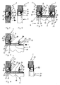
- FIG 1 two containers 1, 2 of conventional design are shown.
- the first container 1 shows that its larger side wall 3 has a large through opening 4, which here also with a cover plate 5 is closed.
- the through opening 4 is comparative wide and goes almost the entire height of the container 1.
- the container 2 has a corresponding Through opening on the side facing away from this view Page on.
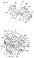
- FIG. 2 shows that the passage opening 4 is open, because the cover plate 5 has been removed. Instead is to the frame profile surrounding the through opening 4 a rectangular bridging profile 6 as a sealing ring scheduled. It is above the level of the side wall 3 before. Its more detailed design results from the figures 5 to 9. are also on the upper corner fittings of the container 1 wedges 7, 8 attached, the closer form results from Figure 12. You stand over protect and protect the level of the bridging profile 6 this when container 2 approaches container 1.
- the second container 2 is - which is not visible here is - also on the side facing away from this view the cover plate there has been removed, however without inserting a bridging profile.
- the open one Through opening has the same position and size as the passage opening 4 in the first container 1.
- FIGS of the two containers 1 and 2 The method for connecting is shown in FIGS of the two containers 1 and 2 by horizontal cross-sectional representations each closer to the same level shown.
- Figure 5 is a section of the side wall 3 of the container 1 with part of the through opening 4 to see.
- the side wall 3 is a sandwich construction with a foam core on the outside is occupied by metal plates.
- the through opening 4 is bordered by a frame profile 9, which is designed as an extruded hollow profile and is attached to the side wall 3.
- the frame profile 9 has an outward-facing edge sealing profile 10.
- an environmental sealing ring 11 is made from the edge sealing profile 10 embedded in an elastomer material. It also has one Keyway 12, which on the facing away from the environmental sealing ring 11 Side is limited by a wedge web 13.
- the cover plate 5 is also from the front Surround frame profile 14.
- the frame profile 14 has On the outside, an edge sealing profile 15, which is essentially complementary to the edge sealing profile 10 the side wall 3 is formed. 5 position shown the edge sealing profile 15 takes Wedge bar 13 and engages in the keyway 12.
- a sealing web 16 is provided which under Bias is applied to the environmental sealing ring 11.
- the border of the wedge web 13 has the edge sealing profile 15 resilient shielding strips 17, 18 on the wedge web 13 and for an electromagnetic Provide shielding.
- the EP-A-0 876 090 in which an essentially matching Sealing between the side wall and a door is described in detail.
- Figure 6 shows the side wall 3 after removal of the cover plate 5.
- Figure 7 shows the bridging profile 6 in on the frame profile 9 fixed position.
- the bridging profile 6 has a central hollow profile section 19 to which Connect overlap webs 20, 21 on the side.
- the in this view left overlap web 20 is on the inside of the frame profile 9 and there is a Variety of screws 22 releasably attached to this.
- a U-shaped groove 25 include, which serves as a gutter.
- the intervention profiles 23, 24 are mirror images and for taken almost identical to the edge sealing profile 15 on the frame profile 14 of the cover plate 5, d. H. complementary to the edge sealing profile 10 of the frame profile 9 on the side wall 3. Accordingly, the engagement profile 23 the wedge web 13 and engages in the Keyway 12 and is also on the environmental sealing ring 11th under tension.
- the engagement profiles 23, 24 have - Like the edge sealing profile 15 - shielding strips 26, 27, 28, 29. The seal between the engagement profile 23 and edge sealing profile 10 is thus equivalent like that between the edge sealing profiles 10 and 15 in the position according to FIG. 5.
- FIG. 8 shows the representation according to FIG. 7 by a corresponding cross-section through the Side wall 30 of the second container 2 added, and in the position shown in Figure 3.
- the cover plate has already been removed, so that the through opening 31 is free.
- the edge of the Through opening 31 is framed by a frame profile 32, the mirror image of the frame profile 9 on the Side wall 3 is formed so that its description referred to that of the frame profile 9 can be. Since the two containers 1, 2 are placed side by side are the through openings 4, 31 and thus also the frame profiles 9, 32 in alignment with each other.
- Figure 9 shows the situation after the contraction of the two containers 1, 2 by means of collets in the figure 4 apparent end position.
- this end position now also engage the right-hand engagement profile 24 and the edge sealing profile 33 of the frame profile 32 complementary into each other, in the same way as the engagement profile 23 in the edge sealing profile 10.
- Da both an environmental sealing ring 36 and the two shielding strips 28, 29 are present is the sealing effect equal to that between the round sealing profile 10 and engagement profile 23, d. H. to this extent there is symmetry.
- the overlap web 21 is not with the frame profile 32 connected. However, one is open Make the connection in the same way as between Overlap web 23 and frame profile 9.
- FIG. 10 shows a collet 37, as used for contraction the container 1, 2 used in the end position becomes. It comes in all four adjacent pairs of corner fittings used, each collet 37 a pair holds together by corner fittings in the end position.
- the collet 37 has a continuous spindle 38, which has two threaded portions 39, 40, which one are clockwise and once counterclockwise. On every thread section 39, 40 an engagement element is screwed on 41, 42, each with an engagement anchor 43, 44 are provided.
- the engagement anchor 43 44 are on the Standard openings in the corner fittings of such containers 1, 2 adjusted so that they fit into this form-fitting can.
- An actuating nut sits on the spindle 38 45, which is rotatably connected to the spindle 38.
- a Lock nut 46 is on the right-hand threaded section 40 screwed on.
- the spindle 38 passes through a guide plate 47, the one Has opening 48.
- a guide pin 49 In the opening 48 is a guide pin 49 with its longitudinal axis parallel to that of the Spindle 38 inserted, so that the guide pin 49 protrudes on both sides of the guide plate 47.
- the guide pin 49 has a cross section that corresponds to the Standard opening of the corner fittings of such containers 1, 2 in this way is adjusted that he just in these openings can border.
- the guide pin is on the right side 49 tapered.
- the attack elements 41, 42 are located in FIG the outer ends of the threaded portions 39, 40 and a distance equal to the distance of the openings in the corner fittings corresponds if the two containers 1, 2 so are placed next to each other, as can be seen from FIG. 3, d. H. if the second container on the wedges 7, 8 is present.
- the engagement anchors 43, 44 into the opening of a pair of two opposite Corner fittings can be used.
- Appropriate collets are also in the openings of the remaining pairs of opposite corner fittings used.
- the guide plate 47 is moved so that it on the respective Corner fitting of the first container 1 abuts and the left-hand part of the guide pin 49 into the opening this corner fitting.
- the end position can be seen from the section according to FIG. 11 see.
- the section shows a corner area of the container 1, 2 with standard corner fittings 50, 51, the top, Openings on the front and on the sides facing each other 52, 53, 54, 55.
- the guide plate 47 forms a stop between the two standard corner fittings 50, 51, the Guide bolt 49 in the openings not visible here the mutually facing surfaces of the standard fittings 50, 51 covered.
- the lock nut 46 is against the right-hand side Engagement element 42 tensioned so that the Spindle 38 cannot twist in one direction would increase the distance between the engagement elements 41, 42.
- the stop function of the guide plate 47 secures with the guide plates of the other collets that the Edge sealing profile. 33 with a defined preload on the engagement profile 24 of the bridging profile 6 for Plant comes, an overuse in this area however is avoided.
- Figure 12 shows the corner area of the container 1 with the Side wall 3, the end wall 56 and the top wall 57.
- side wall 3, end wall 56 and ceiling wall 57 collide in a corner, the outside is formed by the standard fitting 50.
- the deflecting wedge 7 is here on the standard fitting 50 (see Figure 2) attached. It has a base plate 58, which bears against the standard fitting 50. From this base plate 58 goes from a horizontal holding plate 59, the is grasped by a vertical axis 60. On the Axle 60 has an actuating lever 61 on the outside the axis 60 carries a not shown here Gag in the "up” position by the underlying opening 52 in the standard corner fitting 50 fits, in the "closed” position, however, the obvious ones Bordered edges of the opening 52. In the latter Position, the deflecting wedge 7 is fixed to the standard fitting. After turning the operating lever 61 in the The "open" position can be lifted off the standard fitting 50 and be removed. Then you can the collets 37 are attached and contracted.
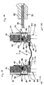
- Figures 13 and 14 correspond in principle to the representation according to Figure 9 with the exception that here is another Sealing ring 71 for connecting two juxtaposed Containers 72, 73 is used.
- the containers 72, 73 here are sections of each other facing side walls 74, 75 and those of them exposed through holes 76, 77 can be seen.
- the Through openings 76, 77 are of frame profiles 78, 79 edged, which are formed as extruded hollow profiles and attached to the associated side wall 74, 75 are.
- the frame profiles 78, 79 each point outwards pointing edge sealing profiles 80, 81, in each an environmental sealing ring 82, 83 made of an elastomer material is let in. They also have keyways 84, 85, on the respective environmental sealing ring 82, 83 facing away from a wedge web 86, 87 bounded become.
- the distance between the two side walls 74, 75 is bridged by the sealing ring 71.
- the sealing ring 71 has two edge rings 88, 89 which over a center ring 90 made of a reinforced elastomeric material are connected.
- the center ring 90 allows compensation of slight differences in position between the two Containers 72, 73.
- the edge rings 88, 89 have clamping rings 91, 92 on that with screws 93, 94 with the edge rings 88, 89 are connected.
- the edge rings 88, 89 have lateral overlap webs 96, 97 on the inside of the frame profiles 78 or 79 and with whom over a variety of Screws are detachably connected. Furthermore, the edge rings 88, 89 engagement profiles 98, 99, which are mirror images are trained and in themselves almost identical with the edge sealing profiles 80, 81 on the frame profiles 78, 79, so they are complementary to these. Corresponding grasp the engagement profiles 98, 99 the wedge webs 86, 87 and engage in the keyways 84, 85. With outer webs 100, 101, they are also due to the environmental sealing rings 82, 83 under tension.
- the engagement profiles 98, 99 each have a shielding strip 102, 103 on that for an electromagnetic Ensure sealing.
Landscapes
- Engineering & Computer Science (AREA)
- Architecture (AREA)
- Physics & Mathematics (AREA)
- Electromagnetism (AREA)
- Civil Engineering (AREA)
- Structural Engineering (AREA)
- Closures For Containers (AREA)
- Stackable Containers (AREA)
- Packages (AREA)
Abstract
Description
Die Erfindung betrifft eine Containergruppe mit wenigstens zwei Containern, die mit zwei Seitenwandungen, welche Durchgangsöffnungen aufweisen, so aneinandergesetzt sind, daß die Durchgangsöffnungen fluchten, wobei die Durchgangsöffnungen mit Randdichtungsprofile aufweisenden Rahmenprofilen eingefaßt sind und der Zwischenraum zwischen den Seitenwandungen durch einen die Durchgangsöffnungen umgebenden Abdichtungsring überbrückt ist. Die Erfindung betrifft ferner ein Verfahren zum Verbinden zweier Container, bei dem die Container mit zwei Seitenwandungen derart aneinandergesetzt werden, daß in den Sei-tenwandungen vorhandene Durchgangsöffnungen fluchten, wobei die Durchgangsöffnungen von Rahmenprofilen mit Randdichtungsgsprofilen eingefaßt sind.The invention relates to a container group with at least two containers, which with two side walls, which Have through openings, so put together are that the through openings are aligned, the Through openings with edge sealing profiles Frame profiles are bordered and the space between the side walls through one of the through openings surrounding sealing ring is bridged. The invention also relates to a method for connecting two Container, in which the container with two side walls can be put together in such a way that in the side walls existing through openings are aligned, whereby the through openings of frame profiles with edge sealing profiles are bordered.
Container werden heute nicht nur für Transportzwecke, sondern auch für besondere Einsatzzwecke verwendet, beispielsweise als militärische oder medizinische Stationen, als umweltstationen oder dergleichen. Sie enthalten dann für den jeweiligen Einsatzzweck angepaßte Geräte, beispielsweise Sende- und Empfangsanlagen, medizinische Versorgungsgeräte, Datenverarbeitungsanlagen, Steuer- und Meßgeräte etc.Today containers are not only used for transport purposes, but also used for special purposes, for example as military or medical stations, as environmental stations or the like. Then they contain Devices adapted for the respective application, for example Transmitting and receiving systems, medical supply devices, Data processing systems, tax and Measuring devices etc.
Solche Container weisen Durchgangsöffnungen auf, die mit Türen oder Fenstern versehen sind. Die Durchgangsöffnungen wie auch Tür und Fenster sind gewöhnlich von einem Rahmenprofil aus einer extrudierten Aluminiumlegierung umgeben, wobei die Rahmenprofile beider Seiten jeweils komplementäre Randdichtungsprofile aufweisen, die bei geschlossener Tür bzw. geschlossenem Fenster abdichtend ineinandergreifen. Dabei sind die Randdichtungsprofile so ausgebildet und ausgerüstet, daß sie eine gute Abdichtung in Anpassung an den jeweiligen Anwendungszweck garantieren. Für zivile Zwecke reichen übliche Umweltdichtungen in Form eines Elastomerstrangs aus, an denen das jeweilige andere Randdichtungsprofil anliegt. Soll der Container gegen hochfrequente Einflüsse abgeschirmt werden, z. B. elektromagnetische Interferrenzen (EMI), elektromagnetische Pulse (EMP) oder nukleare elektromagnetische Pulse (NELP), werden neben einer Umweltdichtung besondere Maßnahmen getroffen, wie sie beispielsweise der EP-A-0 656 742 und der EP-A-0 876 090 zu entnehmen sind. Die die Durchgangsöffnungen einfassenden Randdichtungsprofile sind dabei so ausgebildet, daß die Tür bzw. das Fenster nach außen hin geöffnet werden kann, d. h. die Randdichtungsprofile der Durchgangsöffnungen weisen nach außen, so daß die Randdichtungsprofile von Tür bzw. Fenster von außen her in die der Durchgangsöffnungen eingreifen können. Such containers have through openings that with Doors or windows are provided. The through openings like door and window are usually one Frame profile made of an extruded aluminum alloy surrounded, the frame profiles of both sides have complementary edge sealing profiles that when closed Interlock the door or the closed window. The edge sealing profiles are like this trained and equipped to have a good seal guarantee in adaptation to the respective application. Common environmental seals are sufficient for civil purposes in the form of an elastomer strand, on which the respective other edge sealing profile is present. Should the container be shielded against high-frequency influences, e.g. B. electromagnetic interference (EMI), electromagnetic Pulse (EMP) or nuclear electromagnetic pulse (NELP), in addition to an environmental seal, special measures taken, as for example EP-A-0 656 742 and EP-A-0 876 090. The the Edge sealing profiles enclosing through openings are designed so that the door or window can be opened to the outside, d. H. the edge sealing profiles of the through openings point outwards, so that the edge sealing profiles of the door or window of can engage in the outside of the through openings.
Bei größerem Raumbedarf werden mehrere Container zu einer Containergruppe zusammengesetzt. Dies geschieht in der Weise, daß die Container meist mit ihren größeren Seitenwandungen derart aneinandergesetzt werden, daß ihre Durchgangsöffnungen in Form von Türen miteinander fluchten. Die Türen werden dann herausgenommen, so daß ein Übertritt von einem zum benachbarten Container möglich ist. Zur Überbrückung des Zwischenraums zwischen den Durchgangsöffnungen und zur Abdichtung wird um diese herum eine Faltenbalgabdichtung gelegt.If more space is required, several containers become one Container group composed. This happens in the Way that the containers mostly with their larger side walls are put together so that their Through openings in the form of doors are aligned. The doors are then removed so that a Transfer from one to the neighboring container possible is. To bridge the gap between the Through openings and for sealing is around them a bellows seal placed.
Die vorstehende Lösung ist allenfalls für zivile Zwecke geeignet, da lediglich eine Umweltabdichtung vorgenommen wird und auch diese nicht zuverlässig ist. Der Erfindung liegt somit die Aufgabe zugrunde, die Überbrückung des zwischenraums zwischen den Seitenwandungen einer Containergruppe so auszubilden, daß eine sichere Abdichtung gewährleistet ist und vor allem auch eine Abdichtung gegen hochfrequente Einflüsse möglich ist. Eine weitere Aufgabe besteht darin, ein Verfahren zur Verbindung von zwei Containern zu einer solchen Containergruppe bereitzustellen.The above solution is at most for civil purposes suitable, since only an environmental seal is made and this is also not reliable. The invention is therefore the task of bridging the space between the side walls of a container group to be designed so that a secure seal is guaranteed is and above all a seal against high-frequency influences is possible. Another job is a method of connecting two containers to provide such a container group.
Der erste Teil der Aufgabe wird erfindungsgemäß dadurch gelöst, daß der Abdichtungsring beidseits Eingriffsprofile aufweist, die komplementär zu den Randdichtungsprofilen ausgebildet sind und in diese abdichtend eingreifen. Grundgedanke der Erfindung ist es also, für die Überbrückung des Zwischenraums zwischen den Seitenwandungen einen Abdichtungsring vorzusehen, der an die Randdichtungsprofile der Durchgangsöffnungen so angepaßt ist, daß er in diese eingreift, und zwar vorzugsweise in der gleichen Weise wie die zuvor herausgenommene Abdeckung der Durchgangsöffnungen mittels einer Tür oder einem Seitenwandsegment. Der gegenseitige Eingriff von Randdichtungsprofilen an den Durchgangsöffnungen und Eingriffsprofilen an dem Abdichtungsring sorgt für eine zuverlässige Abdichtung, wobei Randdichtungsprofile und Eingriffsprofile entsprechend dem vorgesehenen Einsatzzweck gestaltet sein können, so daß eine den jeweiligen Anforderungen gerecht werdende Abdichtung bereitgestellt werden kann.The first part of the task is according to the invention solved that the sealing ring on both sides engaging profiles has, which is complementary to the edge sealing profiles are trained and engage sealingly. The basic idea of the invention is therefore for Bridging the space between the side walls to provide a sealing ring attached to the edge sealing profiles the through openings are adapted so that he intervenes in this, preferably in the same way as the cover that was previously removed the through openings by means of a door or a side wall segment. The mutual engagement of edge sealing profiles at the through openings and engagement profiles on the sealing ring ensures a reliable Sealing, with edge sealing profiles and engagement profiles according to the intended purpose can be designed so that the respective requirements adequate sealing are provided can.
Der Abdichtungsring ist zweckmäßigerweise einstückig ausgebildet. Es besteht jedoch auch die Möglichkeit, den Abdichtungsring parallel zur Ebene der Seitenwandung in Teilabdichtungsringe aufzuteilen und die Teilabdichtungsringe über komplementäre Dichtprofilierungen ineinandergreifen zu lassen. Eine solche Ausführungsform kommt in Frage, wenn größere Abstände zwischen den Seitenwandungen der Container überbrückt werden müssen.The sealing ring is expediently formed in one piece. However, there is also the option of the sealing ring parallel to the plane of the side wall in Partial sealing rings to divide and the partial sealing rings interlock via complementary sealing profiles allow. Such an embodiment comes in Question if there are larger gaps between the side walls the container must be bridged.
In weiterer Ausgestaltung der Erfindung ist vorgeschlagen, daß der Abdichtungsring als Überbrückungsprofil - beispielsweise in Form eines extrudierten Profils aus einer Aluminiumlegierung - ausgebildet ist, so daß er eine starre Verbindung zwischen den Containern herstellt. Alternativ dazu kann jedoch auch vorgesehen sein, daß die Eingriffsprofile über einen biegsamen, insbesondere elastischen Mittelring verbunden sind, beispielsweise aus einem mit einer Einlage verstärkten Elastomerband. Diese Ausbildung ist insbesondere für die Aneinanderreihung zu größeren Containerverbänden von Vorteil, da das Abdichtungsprofil Positionstoleranzen und auch Bewegungen des einen Containers gegenüber dem benachbarten aufzunehmen in der Lage ist.In a further embodiment of the invention, it is proposed that that the sealing ring as a bridging profile - for example in the form of an extruded profile from a Aluminum alloy - is designed so that it is a creates a rigid connection between the containers. Alternatively however, it can also be provided that the Engagement profiles via a flexible, especially elastic Center ring are connected, for example an elastomer tape reinforced with an insert. This Training is particularly important for lining up Larger container associations are advantageous because of the sealing profile Positional tolerances and movements of the to hold one container opposite the neighboring one be able to.
In an sich bekannter Weise sollten sich die Randdichtungsprofile auf der dem jeweils gegenüberliegenden Container zugewandten Seite der Rahmenprofile befinden, damit das Überbrückungsprofil von außen her auf das Rahmenprofil unter Eingriff mit dem Randdichtungsprofil aufgesetzt werden und der zweite Container mit seinem Randdichtungsprofil an den Abdichtungsring durch gegenseitige Annäherung der beiden Container angesetzt werden kann, wobei dann auch insoweit ein abdichtender Eingriff bewirkt wird. Dabei sollten die Randdichtungsprofile und die Eingriffsprofile kammartig ineinandergreifen.The edge sealing profiles should be in a manner known per se on the opposite container facing side of the frame profiles the bridging profile from the outside onto the frame profile placed under engagement with the edge sealing profile and the second container with its edge sealing profile to the sealing ring by mutual The two containers can be approximated, in which case a sealing engagement then also results becomes. The edge sealing profiles and the engagement profiles mesh like a comb.
Die Randdichtungsprofile und/oder die Eingriffsprofile sollten einen umweltdichtring aufweisen, gegen die ein Profilsteg des jeweils anderen Elements anliegt. Er kann beispielsweise aus einem Elastomer bestehen, der mit Metallteilchen durchsetzt ist. Sofern eine Abschirmung gegen hochfrequente Einflüsse erforderlich ist, sollten die Eingriffsprofile und/oder die Randdichtungsprofile - vorzugsweise zusätzlich zu der Umweltdichtung - Abschirmelemente aufweisen, wie sie beispielsweise aus der EP-A-0 876 090 und der EP-A-0 656 742 bekannt sind. Hierzu können auch Kontaktflächen beitragen, über die die Randdichtungsprofile und Eingriffsprofile aneinanderliegen.The edge sealing profiles and / or the engagement profiles should have an environmental sealing ring against which a Profile web of the other element is applied. He can for example, consist of an elastomer with metal particles is enforced. If a shield against high frequency influences is required, the Engagement profiles and / or the edge sealing profiles - preferably in addition to the environmental seal - shielding elements have, as for example from EP-A-0 876 090 and EP-A-0 656 742 are known. You can do this also contribute contact areas over which the edge sealing profiles and engagement profiles lie against each other.
In weiterer Ausgestaltung der Erfindung ist vorgesehen, daß der Abdichtungsring außenseitig eine U-förmige Ringnut aufweist, die als Regenrinne dienen kann und vorzugsweise von den Eingriffsprofilen beidseitig begrenzt ist.In a further embodiment of the invention, that the sealing ring has a U-shaped annular groove on the outside has, which can serve as a rain gutter and preferably is limited on both sides by the engagement profiles.
Der Abdichtungsring ist zweckmäßigerweise an einem der Rahmenprofile befestigt. Dies erleichtert das Ansetzen des zweiten Containers. Zur Befestigung kann der Abdichtungsring einen Befestigungssteg aufweisen, der mit der Innenseite des zugehörigen Rahmenprofils überlappt. Die Befestigung sollte zweckmäßigerweise lösbar, beispielsweise über Schrauben, gestaltet sein.The sealing ring is advantageously on one of the Frame profiles attached. This makes it easier to start of the second container. The sealing ring can be used for fastening have a mounting web that with the The inside of the associated frame profile overlaps. The Attachment should expediently be detachable, for example about screws.
Nach der Erfindung ist ferner vorgesehen, daß die Container an zugewandten Paaren von Eckbeschlägen über diese verbindende Spannzangen miteinander verbunden sind. Solche Spannzangen zur Verbindung von zwei Containern sind an sich bekannt. Für die vorliegenden Zwecke sollten die Spannzangen jeweils Eingriffselemente aufweisen, welche in die Eckbeschläge einfassen und jeweils über eine Spindel derart miteinander verbunden sind, daß durch Drehen der Spindel eine Abstandsveränderung der Eingriffselemente und damit der zugehörigen Eckbeschläge bewirkbar ist. Die Spannzangen können dazu benutzt werden, den zweiten, neben den ersten abgesetzten Container an diesen heranzuziehen und damit die Eingriffsprofile des Überbrückungsprofils in Eingriff mit den Abdichtungsprofilen an den Durchgangsöffnungen zu bringen.According to the invention it is further provided that the container on facing pairs of corner fittings over this connecting collets are interconnected. Such Collets for connecting two containers are known per se. For the purposes at hand, the Collets each have engagement elements which surround the corner fittings and each with a spindle are connected to each other in such a way that by turning the spindle a change in distance of the engagement elements and thus the associated corner fittings can be effected. The collets can be used to to pull next to the first deposited container and thus the engagement profiles of the bridging profile in engagement with the sealing profiles on the Bring through openings.
Die Spannzangen haben zweckmäßigerweise jeweils einen Führungsbolzen, der in die einander zugewandten Beschlagsöffnungen der Eckbeschläge passend einfaßt, wobei der Führungsbolzen an einem Ende zugespitzt ist. Die Führungsbolzen sorgen für parallele und fluchtende Annäherung der zu verbindenden Container und wirken zudem zentrierend. Die zugespitzten Enden der Führungsbolzen sollten in die Eckbeschläge desjenigen Containers einfassen, an dem der Abdichtungsring nicht befestigt ist. zweckmäßigerweise sind die Führungsbolzen jeweils auf der zugehörigen Spindel verschieblich geführt.The collets expediently each have one Guide pin, which in the mutually facing fitting openings fits the corner fittings, whereby the guide pin is tapered at one end. The guide bolts ensure parallel and aligned approach of the container to be connected and also have a centering effect. The tapered ends of the guide bolts should fit into the corner fittings of that container, to which the sealing ring is not attached. expediently the guide bolts are each on the corresponding Spindle slidably guided.
Was das Verfahren betrifft, wird die zugehörige Aufgabe
durch folgende Schritte gelöst:
Der erfindungsgemäße Abdichtungsring erlaubt also eine schnelle und problemlose Verbindung von zwei oder mehr Containern, wobei auf diese Weise auch eine Vielzahl von Containern nach und nach aneinandergesetzt werden können. Der von den Containern umgebene Raum kann also beliebig ausgedehnt werden, wobei durch großflächige Durchgangsöffnungen ein störungsfreier Übertritt von einem zum benachbarten Container ermöglicht wird.The sealing ring according to the invention thus allows one quick and easy connection of two or more Containers, this way also a variety of Containers can be put together little by little. The space surrounded by the containers can therefore be any be extended, with large through openings a trouble-free transition from one to the neighboring Container is made possible.
Zweckmäßigerweise sollten die beiden Container an ihren Eckbeschlägen, beispielsweise durch die vorgenannten Spannzangen, zusammengezogen werden.The two containers should be conveniently attached to their Corner fittings, for example by the aforementioned Collets to be pulled together.
Zum Schutz des an dem ersten Container angebrachten Abdichtungsrings sollte an einem der Container, zweckmäßigerweise an dem ersten Container, vor dem Absetzen des anzuschließenden zweiten Containers neben den ersten Container Abweisvorsprünge angebracht werden, die über dem Abdichtungsring vorstehen. Diese Abweisvorsprünge werden vorzugsweise an den Eckbeschlägen angebracht. Nach dem Absetzen des anzuschließenden Containers werden sie abgenommen, damit die beiden Container anschließend mittels Spannzangen einander angenähert werden können.To protect the sealing ring attached to the first container should be on one of the containers, conveniently on the first container, before setting down the second container to be connected next to the first container Repeller protrusions are attached, which over the Protrude sealing ring. These rejection tabs will be preferably attached to the corner fittings. After this They are removed from the container to be connected, so that the two containers can then be Collets can be approximated.
In der Zeichnung ist die Erfindung anhand eines Ausführungsbeispiels näher veranschaulicht. Es zeigen:
Figur 1- eine Schrägansicht von zwei Containern in versetzter Stellung;
Figur 2- eine Schrägansicht der zwei Container in
der Stellung gemäß
Figur 1 nach Anbringung des Überbrückungsprofils und von Abweiskeilen; Figur 3- eine Schrägansicht der beiden Container gemäß
den
Figuren 1 und 2 in nebeneinandergesetzter Stellung, jedoch noch im Abstand zueinander; Figur 4- eine Schrägansicht der
Container gemäß Figur 3 in aneinanderliegender Stellung; Figur 5- einen Querschnitt durch die Seitenwandung des ersten Containers im Bereich ihrer Durchgangsöffnung;
Figur 6- den
Querschnitt gemäß Figur 5 nach Herausnahme der Abdeckung der Durchgangsöffnung; Figur 7- einen Querschnitt durch die Seitenwandung
gemäß den Figuren 5 und 6 mit angebrachtem Überbrückungsprofil; Figur 8- den
Querschnitt gemäß Figur 7 mit Querschnitt durch die Seitenwandung des nebenan gesetzten zweiten Containers; Figur 9- einen Querschnitt durch die Seitenwandungen der beiden Container mit Eingriff des Überbrückungsprofils in beide Rahmenprofile;
Figur 10- eine Schrägansicht einer Spannzange;
Figur 11- eine Detailansicht von zwei Eckbeschlägen der beiden Container mit Spannzange in der Endstellung;
Figur 12- eine Schrägansicht auf einen Eckbeschlag des ersten Containers mit daran angebrachtem Abweiskeil 11;
Figur 13- einen Querschnitt durch die Seitenwandungen von zwei benachbarten Containern im Bereich ihrer Durchgangsöffnung mit Abdichtungsring;
Figur 14- eine Detailvergrößerung des Abdichtungsrings
gemäß
Figur 13.
- Figure 1
- an oblique view of two containers in the offset position;
- Figure 2
- an oblique view of the two containers in the position shown in Figure 1 after attaching the bridging profile and bumpers;
- Figure 3
- an oblique view of the two containers according to Figures 1 and 2 in juxtaposed position, but still at a distance from each other;
- Figure 4
- an oblique view of the container of Figure 3 in a contiguous position;
- Figure 5
- a cross section through the side wall of the first container in the region of its passage opening;
- Figure 6
- the cross section of Figure 5 after removing the cover of the through hole;
- Figure 7
- a cross-section through the side wall according to Figures 5 and 6 with attached bridging profile;
- Figure 8
- the cross section of Figure 7 with a cross section through the side wall of the second container placed next door;
- Figure 9
- a cross section through the side walls of the two containers with engagement of the bridging profile in both frame profiles;
- Figure 10
- an oblique view of a collet;
- Figure 11
- a detailed view of two corner fittings of the two containers with collet in the end position;
- Figure 12
- an oblique view of a corner fitting of the first container with a
wedge 11 attached; - Figure 13
- a cross section through the side walls of two adjacent containers in the region of their through opening with a sealing ring;
- Figure 14
- a detailed enlargement of the sealing ring according to Figure 13.
In Figur 1 sind zwei Container 1, 2 üblicher Bauart dargestellt.
Bei dem ersten Container 1 ist zu sehen, daß
seine größere Seitenwandung 3 eine große Durchgangsöffnung
4 aufweist, welche hier noch mit einer Abdeckplatte
5 verschlossen ist. Die Durchgangsöffnung 4 ist vergleichsweise
breit und geht nahezu über die gesamte Höhe
des Containers 1. Der Container 2 weist eine entsprechende
Durchgangsöffnung auf der in dieser Ansicht abgewandten
Seite auf.In Figure 1, two
Figur 2 zeigt, daß die Durchgangsöffnung 4 offen ist,
weil die Abdeckplatte 5 entfernt worden ist. Statt dessen
ist an das die Durchgangsöffnung 4 umgebende Rahmenprofil
ein rechteckiges überbrückungsprofil 6 als Abdichtungsring
angesetzt. Es steht über die Ebene der Seitenwandung
3 vor. Seine nähere Ausgestaltung ergibt sich aus den Figuren
5 bis 9. zusätzlich sind an den oberen Eckbeschlägen
des Container 1 Abweiskeile 7, 8 angebracht, deren
näherer Gestalt sich aus Figur 12 ergibt. Sie stehen über
die Ebene des Überbrückungsprofils 6 vor und schützen
dies beim Annähern des Containers 2 an den Container 1.FIG. 2 shows that the
Bei dem zweiten Container 2 ist - was hier nicht sichtbar
ist - auf der in dieser Ansicht abgewandten Seite ebenfalls
die dort vorhandene Abdeckplatte entfernt worden,
jedoch ohne Einsetzen eines Überbrückungsprofils. Die offene
Durchgangsöffnung hat die gleiche Lage und Größe wie
die Durchgangsöffnung 4 in dem ersten Container 1.The
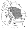
In Figur 3 sind die beiden Container 1, 2 nebeneinander
gesetzt, so daß ihre Stirnseiten bündig zueinander liegen.
In dieser Stellung fluchten die beiden Durchgangsöffnungen
4, wobei jedoch der Abstand zwischen den beiden
Containern 1, 2 aufgrund der Abweiskeile 7, 8 noch so
groß ist, daß das am Container 1 befestigte Überbrückungsprofil
6 diesen Abstand nicht vollständig überbrückt.In Figure 3, the two
In Figur 4 sind die beiden Container 1, 2 auf Anschlag
aneinandergezogen. Dies ist mit Hilfe von Spannzangen,
wie sie sich aus den Figuren 10 und 11 ergeben, bewirkt
worden. In dieser Stellung liegt das Überbrückungsprofil
6 an dem Rahmenprofil der Durchgangsöffnung des Containers
2 an, so daß die beiden Durchgangsöffnungen 4 nach
außen hin abgedichtet sind. Die Spannzangen sichern, daß
die beiden Container 1, 2 ihre zueinander definierte
Stellung auch bei Bodenveränderungen, Erschütterungen
oder dergleichen beibehalten.In Figure 4, the two
In den Figuren 5 bis 9 ist das Verfahren zum Verbinden
der beiden Container 1 und 2 durch horizontale Querschnittsdarstellungen
jeweils in derselben Ebene näher
dargestellt. In Figur 5 ist ausschnittweise die Seitenwandung
3 des Containers 1 mit einem Teil der Durchgangsöffnung
4 zu sehen. Die Seitenwandung 3 ist als Sandwichkonstruktion
mit einem Schaumstoffkern, der außenseitig
von Metallplatten belegt ist, ausgeführt.The method for connecting is shown in FIGS
of the two
Die Durchgangsöffnung 4 ist von einem Rahmenprofil 9 eingefaßt,
das als Strangpreßhohlprofil ausgebildet ist und
an der Seitenwandung 3 befestigt ist. Das Rahmenprofil 9
hat ein nach außen weisendes Randdichtungsprofil 10. In
dem Randdichtungsprofil 10 ist ein Umweltdichtring 11 aus
einem Elastomermaterial eingelassen. Es weist zudem eine
Keilnut 12 ein, die auf der dem Umweltdichtring 11 abgewandten
Seite von einem Keilsteg 13 begrenzt wird.The through
Die Abdeckplatte 5 ist stirnseitig ebenfalls von einem
Rahmenprofil 14 umgeben. Das Rahmenprofil 14 weist zur
Außenseite hin ein Randdichtungsprofil 15 auf, das im wesentlichen
komplementär zu dem Randdichtungsprofil 10 an
der Seitenwandung 3 ausgebildet ist. In der in Figur 5
gezeigten Stellung nimmt das Randdichtungsprofil 15 den
Keilsteg 13 auf und greift in die Keilnut 12 ein. Am
freien Rand ist ein Dichtsteg 16 vorgesehen, der unter
Vorspannung an dem Umweltdichtring 11 anliegt. Im Bereich
der Einfassung des Keilstegs 13 weist das Randdichtungsprofil
15 federnde Abschirmstreifen 17, 18 auf, die an
dem Keilsteg 13 anliegen und für eine elektromagnetische
Abschirmung sorgen. Insoweit näheres ist der EP-A-0 876
090 zu entnehmen, in der eine im wesentlichen übereinstimmende
Abdichtung zwischen Seitenwandung und einer Tür
im einzelnen beschrieben ist.The
Figur 6 zeigt die Seitenwandung 3 nach Entfernung der Abdeckplatte
5. In dieser Darstellung ist die Profilierung
des Rahmenprofils 9 und insbesondere des Randdichtungsprofils
10 deutlicher zu erkennen.Figure 6 shows the
Figur 7 zeigt das Überbrückungsprofil 6 in an dem Rahmenprofil
9 befestigter Stellung. Das Überbrückungsprofil 6
hat einen mittleren Hohlprofilabschnitt 19, an den sich
seitlich Überlappungsstege 20, 21 anschließen. Der in
dieser Ansicht linke Überlappungssteg 20 liegt an der Innenseite
des Rahmenprofils 9 an und ist dort über eine
Vielzahl von Schrauben 22 an diesem lösbar befestigt.Figure 7 shows the
An den Übergängen zwischen Hohlprofilabschnitt 19 und den
Überlappungsstegen 20, 21 sind Eingriffsprofile 23, 24
ausgeformt, die zwischen sich eine U-förmige Rinne 25
einschließen, welche als Regenrinne dient. Die Eingriffsprofile
23, 24 sind spiegelbildlich ausgebildet und für
sich genommen nahezu identisch mit dem Randdichtungsprofil
15 am Rahmenprofil 14 der Abdeckplatte 5, d. h. komplementär
zu dem Randdichtungsprofil 10 des Rahmenprofils
9 an der Seitenwandung 3. Entsprechend faßt das Eingriffsprofil
23 den Keilsteg 13 ein und greift in die
Keilnut 12 ein und liegt auch an dem Umweltdichtring 11
unter Vorspannung an. Die Eingriffsprofile 23, 24 weisen
- wie das Randdichtungsprofil 15 - Abschirmungsstreifen
26, 27, 28, 29 auf. Die Abdichtung zwischen Eingriffsprofil
23 und Randdichtungsprofil 10 ist somit gleichwirkend
wie die zwischen den Randdichtungsprofilen 10 und 15 in
der Stellung gemäß Figur 5.At the transitions between the
In Figur 8 ist die Darstellung gemäß Figur 7 durch einen
entsprechenden, ausschnittweisen Querschnitt durch die
Seitenwandung 30 des zweiten Containers 2 ergänzt, und
zwar in der sich aus Figur 3 ergebenden Stellung. In der
Seitenwandung 30 ist die Abdeckplatte schon entfernt, so
daß die Durchgangsöffnung 31 frei ist. Der Rand der
Durchgangsöffnung 31 ist durch ein Rahmenprofil 32 eingefaßt,
das spiegelbildlich zu dem Rahmenprofil 9 an der
Seitenwandung 3 ausgebildet ist, so daß zu dessen Beschreibung
auf die des Rahmenprofils 9 Bezug genommen
werden kann. Da die beiden Container 1, 2 nebeneinandergestellt
sind, stehen sich die Durchgangsöffnungen 4, 31
und damit auch die Rahmenprofile 9, 32 fluchtend gegenüber.FIG. 8 shows the representation according to FIG. 7 by a
corresponding cross-section through the
Figur 9 zeigt die Situation nach dem Zusammenziehen der
beiden Container 1, 2 mittels Spannzangen in die aus Figur
4 ersichtliche Endstellung. In dieser Endstellung
greifen jetzt auch das rechtseitige Eingriffsprofil 24
und das Randdichtungsprofil 33 des Rahmenprofils 32 komplementär
ineinander, und zwar in der gleichen Weise wie
das Eingriffsprofil 23 in das Randdichtungsprofil 10. Da
sowohl ein Umweltdichtungsring 36 als auch die beiden Abschirmstreifen
28, 29 vorhanden sind, ist die Dichtungswirkung
gleich derjenigen zwischen Runddichtungsprofil 10
und Eingriffsprofil 23, d. h. insoweit ist Symmetrie gegeben.
Der Überlappungssteg 21 ist nicht mit dem Rahmenprofil
32 verbunden. Es steht jedoch offen, eine solche
Verbindung in der gleichen Weise vorzunehmen wie zwischen
Überlappungssteg 23 und Rahmenprofil 9.Figure 9 shows the situation after the contraction of the
two
Figur 10 zeigt eine Spannzange 37, wie sie für das Zusammenziehen
der Container 1, 2 in die Endetellung verwendet
wird. Sie wird in alle vier benachbarten Paare von Eckbeschlägen
eingesetzt, wobei jede Spannzange 37 ein Paar
von Eckbeschlägen in der Endstellung zusammenhält.FIG. 10 shows a
Die Spannzange 37 weist eine durchgehende Spindel 38 auf,
die zwei Gewindeabschnitte 39, 40 hat, welche einmal
rechtsdrehend und einmal linksdrehend sind. Auf jeden Gewindeabschnitt
39, 40 aufgeschraubt ist ein Eingriffselement
41, 42, die jeweils mit einem Eingriffsanker 43, 44
versehen sind. Die Eingriffsanker 43 44 sind an die
Normöffnungen in den Eckbeschlägen solcher Container 1, 2
angepaßt, so daß sie in diese formschlüssig einfassen
können. Auf der Spindel 38 sitzt eine Betätigungsmutter
45, die mit der Spindel 38 drehfest verbunden ist. Eine
Kontermutter 46 ist auf den rechtsseitigen Gewindeabschnitt
40 aufgeschraubt.The
Die Spindel 38 durchsetzt eine Führungsplatte 47, die eine
Öffnung 48 aufweist. In die Öffnung 48 ist ein Führungsbolzen
49 mit seiner Längsachse parallel zu der der
Spindel 38 eingesetzt, und zwar so, daß der Führungsbolzen
49 zu beiden Seiten der Führungsplatte 47 vorspringt.
Der Führungsbolzen 49 hat einen Querschnitt, der an die
Normöffnung der Eckbeschläge solcher Container 1, 2 dergestalt
angepaßt ist, daß er gerade in diese Öffnungen
einfassen kann. Auf der rechten Seite ist der Führungsbolzen
49 konisch zugespitzt.The
In Figur 10 befinden sich die Angriffselemente 41, 42 an
den äußeren Enden der Gewindeabschnitte 39, 40 und haben
ein Abstand, der dem Abstand der Öffnungen in den Eckbeschlägen
entspricht, wenn die beiden Container 1, 2 so
aneinandergesetzt sind, wie aus Figur 3 ersichtlich,
d. h. wenn der zweite Container an den Abweiskeilen 7, 8
anliegt. In dieser Stellung können die Eingriffsanker 43,
44 in die Öffnung eines Paars von zwei gegenüberliegenden
Eckbeschlägen eingesetzt werden. Entsprechende Spannzangen
werden auch in die Öffnungen der übrigen Paare von
gegenüberliegenden Eckbeschlägen eingesetzt. Die Führungsplatte
47 wird so verschoben, daß sie an dem jeweiligen
Eckbeschlag des ersten Containers 1 anliegt und der
linksseitige Teil des Führungsbolzens 49 in die Öffnung
dieses Eckbeschlags einfaßt. Dann werden die Betätigungsmuttern
45 aller Spannzangen 37 so verdreht, daß sich der
Abstand der Eingriffselemente 41, 42 verringert. Hierdurch
werden die jeweils gegenüberliegenden Eckbeschläge
sukzessive zusammengezogen, d.h. der zweite Container 2
wird im wesentlichen parallel an den ersten Container 1
herangezogen. Dabei fahren die zugespitzten Teile der
Führungsbolzen 49 in die Öffnungen der Eckbeschläge des
Containers 2 ein und wirken dabei auch zentrierend.The
Die Endstellung ist aus dem Ausschnitt gemäß Figur 11 zu
sehen. Der Ausschnitt zeigt einen Eckbereich der Container
1, 2 mit Normeckbeschlägen 50, 51, die obenseitig,
stirnseitig und an den einander zugewandten Seiten Öffnungen
52, 53, 54, 55 aufweisen. In die stirnseitigen
Öffnungen 54, 55 sind die Eingriffsanker 43, 44
(gestrichelt gezeichnet) der Eingriffselemente 41, 42
eingesetzt. Die Führungsplatte 47 bildet einen Anschlag
zwischen den beiden Normeckbeschlägen 50, 51, wobei der
Führungsbolzen 49 die hier nicht sichtbaren Öffnungen in
den einander zugewandten Flächen der Normeckbeschläge 50,
51 durchfaßt. Die Kontermutter 46 ist gegen das rechtsseitige
Eingriffselement 42 gespannt, so daß sich die
Spindel 38 nicht in einer Richtung verdrehen kann, die
den Abstand der Eingriffselemente 41, 42 vergrößern würde.
Die Anschlagfunktion der Führungsplatte 47 sichert
mit den Führungsplatten der übrigen Spannzangen, daß das
Randdichtungsprofil. 33 mit einer definierten Vorspannung
an dem Eingriffsprofil 24 des Überbrückungsprofils 6 zur
Anlage kommt, eine Überbeanspruchung in diesem Bereich
jedoch vermieden wird.The end position can be seen from the section according to FIG. 11
see. The section shows a corner area of the
Figur 12 zeigt den Eckbereich des Containers 1 mit der
Seitenwandung 3, der Stirnwandung 56 und der Deckenwandung
57. Seitenwandung 3, Stirnwandung 56 und Deckenwandung
57 stoßen in einer Ecke zusammen, die außenseitig
von dem Normeckbeschlag 50 gebildet wird.Figure 12 shows the corner area of the
An dem Normeckbeschlag 50 ist hier der Abweiskeil 7
(vergleiche Figur 2) angebracht. Er hat eine Basisplatte
58, die an dem Normeckbeschlag 50 anliegt. Von dieser Basisplatte
58 geht eine horizontale Halteplatte 59 ab, die
von einer vertikalen Achse 60 durchfaßt wird. Auf der
Achse 60 sitzt außenseitig ein Betätigungshebel 61. Innenseitig
trägt die Achse 60 einen hier nicht näher dargestellten
Knebel, der in der Stellung "Auf" durch die
darunterliegende Öffnung 52 in den Normeckbeschlag 50
paßt, in der Stellung "Zu" jedoch die einander naheliegenden
Ränder der Öffnung 52 hinterfaßt. In der letzteren
Stellung ist der Abweiskeil 7 an dem Normeckbeschlag fixiert.
Nach Verdrehen des Betätigungshebels 61 in die
Stellung "Auf" kann er von dem Normeckbeschlag 50 abgehoben
und entfernt werden. Im Anschluß daran können dann
die Spannzangen 37 angesetzt und zusammengezogen werden. The deflecting
Die Figuren 13 und 14 entsprechen prinzipiell der Darstellung
gemäß Figur 9 mit der Ausnahme, daß hier ein anderer
Abdichtungsring 71 zur Verbindung von zwei nebeneinandergestellten
Containern 72, 73 verwendet wird. Von
den Containern 72, 73 sind hier Abschnitte der einander
zugewandten Seitenwandungen 74, 75 sowie die von ihnen
freigelassenen Durchgangsöffnungen 76, 77 zu sehen. Die
Durchgangsöffnungen 76, 77 sind von Rahmenprofilen 78, 79
eingefaßt, die als Strangpreßhohlprofile ausgebildet und
an der jeweils zugehörenden Seitenwand 74, 75 befestigt
sind. Die Rahmenprofile 78, 79 weisen jeweils nach außen
weisende Randdichtungsprofile 80, 81 auf, in die jeweils
ein Umweltdichtring 82, 83 aus einem Elastomermaterial
eingelassen ist. Sie weisen zudem Keilnuten 84, 85 auf,
die auf der dem jeweils zugehörenden Umweltdicht-ring 82,
83 abgewandten Seite von einem Keilsteg 86, 87 begrenzt
werden.Figures 13 and 14 correspond in principle to the representation
according to Figure 9 with the exception that here is another
Die Distanz zwischen den beiden Seitenwandungen 74, 75
wird von dem Abdichtungsring 71 überbrückt. Der Abdichtungsring
71 weist zwei Randringe 88, 89 auf, die über
einen Mittelring 90 aus einem verstärkten Elastomermaterial
verbunden sind. Der Mittelring 90 erlaubt den Ausgleich
von geringen Positionsunterschieden der beiden
Container 72, 73. Die Randringe 88, 89 weisen Klemmringe
91, 92 auf, die über Schrauben 93, 94 mit den Randringen
88, 89 verbunden sind. Wie insbesondere Figur 14 zu entnehmen
ist, weisen die Randringe 88, 89 an den den Klemmringen
91, 92 zugewandten Seiten Rippen - beispielhaft
mit 95 bezeichnet - auf, die den Halt des Mittelrings 90
und die Abdichtung in diesem Bereich verbessern.The distance between the two
Die Randringe 88, 89 weisen seitliche Überlappungsstege
96, 97 auf, die an den Innenseiten der Rahmenprofile 78
bzw. 79 anliegen und mit denen über eine Vielzahl von
Schrauben lösbar verbunden sind. Ferner haben die Randringe
88, 89 Eingriffsprofile 98, 99, welche spiegelbildlich
ausgebildet sind und für sich genommen nahezu identisch
mit den Randdichtungsprofilen 80, 81 an den Rahmenprofilen
78, 79, also komplementär zu diesen sind. Entsprechend
fassen die Eingriffsprofile 98, 99 die Keilstege
86, 87 ein und greifen in die Keilnuten 84, 85 ein.
Mit äußeren Stegen 100, 101 liegen sie auch an den Umweltdichtringen
82, 83 unter Vorspannung an.The edge rings 88, 89 have
Die Eingriffsprofile 98, 99 weisen jeweils einen Abschirmstreifen
102, 103 auf, die für eine elektromagnetische
Abdichtung sorgen.The engagement profiles 98, 99 each have a
Claims (23)
Applications Claiming Priority (2)
| Application Number | Priority Date | Filing Date | Title |
|---|---|---|---|
| DE19920613 | 1999-05-05 | ||
| DE19920613 | 1999-05-05 |
Publications (2)
| Publication Number | Publication Date |
|---|---|
| EP1050488A2 true EP1050488A2 (en) | 2000-11-08 |
| EP1050488A3 EP1050488A3 (en) | 2002-11-27 |
Family
ID=7907020
Family Applications (1)
| Application Number | Title | Priority Date | Filing Date |
|---|---|---|---|
| EP00105841A Withdrawn EP1050488A3 (en) | 1999-05-05 | 2000-03-20 | Group of containers and method of connecting the containers |
Country Status (2)
| Country | Link |
|---|---|
| EP (1) | EP1050488A3 (en) |
| DE (1) | DE20005214U1 (en) |
Families Citing this family (4)
| Publication number | Priority date | Publication date | Assignee | Title |
|---|---|---|---|---|
| DE102004002945A1 (en) * | 2004-01-21 | 2005-08-11 | Dennert Poraver Gmbh | Fire protection container, with side walls, a cover and/or base, including a framework of support stays useful in the chemical and pharmaceutical industries for storage of potentially explosion and fire risk materials |
| DE102004031466B4 (en) | 2004-06-30 | 2015-07-30 | Ulrich Malchow | Device for receiving goods |
| EP2357291A1 (en) * | 2010-02-12 | 2011-08-17 | Hsu-Hua Huang | Modular architecture |
| DE102011053306A1 (en) * | 2011-09-06 | 2013-03-07 | Drehtainer Gmbh Spezial Container- Und Fahrzeugbau | Vehicle with semi-trailer in modular design |
Citations (2)
| Publication number | Priority date | Publication date | Assignee | Title |
|---|---|---|---|---|
| EP0656742A1 (en) | 1993-12-01 | 1995-06-07 | M. Schall GmbH + Co. KG | High frequency waves or pulses shielding device |
| EP0876090A2 (en) | 1997-03-14 | 1998-11-04 | M. Schall GmbH + Co. KG | Housing with walls and at least one opening in them |
Family Cites Families (5)
| Publication number | Priority date | Publication date | Assignee | Title |
|---|---|---|---|---|
| GB1228200A (en) * | 1968-11-14 | 1971-04-15 | ||
| US4492384A (en) * | 1983-04-25 | 1985-01-08 | General Motors Corporation | Sealing arrangement |
| US4599829A (en) * | 1983-08-25 | 1986-07-15 | Tandemloc, Inc. | Modular container building system |
| US5280984A (en) * | 1992-10-02 | 1994-01-25 | Paccar Inc. | Walk through boot assembly and method |
| US5735639A (en) * | 1996-12-13 | 1998-04-07 | The United States Of America As Represented By The Secretary Of The Navy | Modular mobile safety structure for containment and handling of hazardous materials |
-
2000
- 2000-03-18 DE DE20005214U patent/DE20005214U1/en not_active Expired - Lifetime
- 2000-03-20 EP EP00105841A patent/EP1050488A3/en not_active Withdrawn
Patent Citations (2)
| Publication number | Priority date | Publication date | Assignee | Title |
|---|---|---|---|---|
| EP0656742A1 (en) | 1993-12-01 | 1995-06-07 | M. Schall GmbH + Co. KG | High frequency waves or pulses shielding device |
| EP0876090A2 (en) | 1997-03-14 | 1998-11-04 | M. Schall GmbH + Co. KG | Housing with walls and at least one opening in them |
Also Published As
| Publication number | Publication date |
|---|---|
| EP1050488A3 (en) | 2002-11-27 |
| DE20005214U1 (en) | 2000-08-17 |
Similar Documents
| Publication | Publication Date | Title |
|---|---|---|
| EP0853832B1 (en) | Framework for switchgear cabinets | |
| EP0751595B1 (en) | Frame for a switchgear cabinet | |
| DE2932998A1 (en) | DEVICE FOR DETACHABLE FLEXIBLE PARTS, EXAMPLE OF A FLEXIBLE COVER | |
| EP1994614B1 (en) | Frame construction for a switchgear cabinet, switchgear cabinet and construction kit for the switchgear cabinet | |
| DE1683009B2 (en) | Folding door with at least two panels | |
| DE3229814A1 (en) | ARRANGEMENT FOR CONNECTING SURFACE-SHAPED ELEMENTS ON NEIGHBORING LONG EDGES | |
| EP0681081A1 (en) | Closure for wall openings in buildings or the like | |
| EP0444405A2 (en) | Door or window fitting | |
| EP0342478A2 (en) | Base for a switchboard or the like | |
| DE8030908U1 (en) | DEVICE FOR CONNECTING PANELS AND / OR RODS | |
| EP1050488A2 (en) | Group of containers and method of connecting the containers | |
| DE2851549B1 (en) | Device for connecting formwork panels, in particular in the area of steps of a building | |
| WO1999012657A1 (en) | Wall for the cabin of a varnishing line | |
| EP0269126B1 (en) | Screened case | |
| DE2516264C2 (en) | Fastening device for a fitting part on profile rods made of metal or plastic | |
| DE1690003C3 (en) | Dismountable box for storing electrical devices | |
| DE3230287A1 (en) | X-ray film cassette | |
| DE2119362A1 (en) | Fixing device for connecting formwork panels | |
| EP1495996B1 (en) | Slat conveyor chain with guide device | |
| EP0876090B1 (en) | Housing with walls and at least one opening in them | |
| DE2546087C2 (en) | Box elements for an insulating-encapsulated switchgear with switchgear, control and regulating device | |
| EP0562500B1 (en) | Escutcheon assembly for cylinder lock | |
| WO1984000572A1 (en) | Sheeting device | |
| DE102019001906A1 (en) | Adjustable door leaf | |
| EP0465905A1 (en) | Ceiling cladding |
Legal Events
| Date | Code | Title | Description |
|---|---|---|---|
| PUAI | Public reference made under article 153(3) epc to a published international application that has entered the european phase |
Free format text: ORIGINAL CODE: 0009012 |
|
| AK | Designated contracting states |
Kind code of ref document: A2 Designated state(s): AT BE CH CY DE DK ES FI FR GB GR IE IT LI LU MC NL PT SE |
|
| AX | Request for extension of the european patent |
Free format text: AL;LT;LV;MK;RO;SI |
|
| RIC1 | Information provided on ipc code assigned before grant |
Free format text: 7B 65D 90/00 A, 7E 04B 1/348 B, 7B 65D 88/02 B |
|
| PUAL | Search report despatched |
Free format text: ORIGINAL CODE: 0009013 |
|
| AK | Designated contracting states |
Kind code of ref document: A3 Designated state(s): AT BE CH CY DE DK ES FI FR GB GR IE IT LI LU MC NL PT SE |
|
| AX | Request for extension of the european patent |
Free format text: AL;LT;LV;MK;RO;SI |
|
| AKX | Designation fees paid | ||
| REG | Reference to a national code |
Ref country code: DE Ref legal event code: 8566 |
|
| STAA | Information on the status of an ep patent application or granted ep patent |
Free format text: STATUS: THE APPLICATION IS DEEMED TO BE WITHDRAWN |
|
| 18D | Application deemed to be withdrawn |
Effective date: 20030527 |