EP1045391A1 - Method and device for recording information in units - Google Patents
Method and device for recording information in units Download PDFInfo
- Publication number
- EP1045391A1 EP1045391A1 EP99201185A EP99201185A EP1045391A1 EP 1045391 A1 EP1045391 A1 EP 1045391A1 EP 99201185 A EP99201185 A EP 99201185A EP 99201185 A EP99201185 A EP 99201185A EP 1045391 A1 EP1045391 A1 EP 1045391A1
- Authority
- EP
- European Patent Office
- Prior art keywords
- mark
- link
- marks
- runlength
- recording
- Prior art date
- Legal status (The legal status is an assumption and is not a legal conclusion. Google has not performed a legal analysis and makes no representation as to the accuracy of the status listed.)
- Withdrawn
Links
Images


Classifications
-
- G—PHYSICS
- G11—INFORMATION STORAGE
- G11B—INFORMATION STORAGE BASED ON RELATIVE MOVEMENT BETWEEN RECORD CARRIER AND TRANSDUCER
- G11B20/00—Signal processing not specific to the method of recording or reproducing; Circuits therefor
- G11B20/10—Digital recording or reproducing
- G11B20/14—Digital recording or reproducing using self-clocking codes
- G11B20/1403—Digital recording or reproducing using self-clocking codes characterised by the use of two levels
- G11B20/1423—Code representation depending on subsequent bits, e.g. delay modulation, double density code, Miller code
- G11B20/1426—Code representation depending on subsequent bits, e.g. delay modulation, double density code, Miller code conversion to or from block codes or representations thereof
-
- G—PHYSICS
- G11—INFORMATION STORAGE
- G11B—INFORMATION STORAGE BASED ON RELATIVE MOVEMENT BETWEEN RECORD CARRIER AND TRANSDUCER
- G11B20/00—Signal processing not specific to the method of recording or reproducing; Circuits therefor
- G11B20/00007—Time or data compression or expansion
-
- G—PHYSICS
- G11—INFORMATION STORAGE
- G11B—INFORMATION STORAGE BASED ON RELATIVE MOVEMENT BETWEEN RECORD CARRIER AND TRANSDUCER
- G11B20/00—Signal processing not specific to the method of recording or reproducing; Circuits therefor
- G11B20/10—Digital recording or reproducing
- G11B20/12—Formatting, e.g. arrangement of data block or words on the record carriers
- G11B20/1217—Formatting, e.g. arrangement of data block or words on the record carriers on discs
-
- G—PHYSICS
- G11—INFORMATION STORAGE
- G11B—INFORMATION STORAGE BASED ON RELATIVE MOVEMENT BETWEEN RECORD CARRIER AND TRANSDUCER
- G11B27/00—Editing; Indexing; Addressing; Timing or synchronising; Monitoring; Measuring tape travel
- G11B27/10—Indexing; Addressing; Timing or synchronising; Measuring tape travel
- G11B27/19—Indexing; Addressing; Timing or synchronising; Measuring tape travel by using information detectable on the record carrier
- G11B27/28—Indexing; Addressing; Timing or synchronising; Measuring tape travel by using information detectable on the record carrier by using information signals recorded by the same method as the main recording
- G11B27/30—Indexing; Addressing; Timing or synchronising; Measuring tape travel by using information detectable on the record carrier by using information signals recorded by the same method as the main recording on the same track as the main recording
- G11B27/3027—Indexing; Addressing; Timing or synchronising; Measuring tape travel by using information detectable on the record carrier by using information signals recorded by the same method as the main recording on the same track as the main recording used signal is digitally coded
-
- G—PHYSICS
- G11—INFORMATION STORAGE
- G11B—INFORMATION STORAGE BASED ON RELATIVE MOVEMENT BETWEEN RECORD CARRIER AND TRANSDUCER
- G11B20/00—Signal processing not specific to the method of recording or reproducing; Circuits therefor
- G11B20/10—Digital recording or reproducing
- G11B20/12—Formatting, e.g. arrangement of data block or words on the record carriers
- G11B20/1217—Formatting, e.g. arrangement of data block or words on the record carriers on discs
- G11B2020/1218—Formatting, e.g. arrangement of data block or words on the record carriers on discs wherein the formatting concerns a specific area of the disc
- G11B2020/1238—Formatting, e.g. arrangement of data block or words on the record carriers on discs wherein the formatting concerns a specific area of the disc track, i.e. the entire a spirally or concentrically arranged path on which the recording marks are located
-
- G—PHYSICS
- G11—INFORMATION STORAGE
- G11B—INFORMATION STORAGE BASED ON RELATIVE MOVEMENT BETWEEN RECORD CARRIER AND TRANSDUCER
- G11B20/00—Signal processing not specific to the method of recording or reproducing; Circuits therefor
- G11B20/10—Digital recording or reproducing
- G11B20/12—Formatting, e.g. arrangement of data block or words on the record carriers
- G11B2020/1264—Formatting, e.g. arrangement of data block or words on the record carriers wherein the formatting concerns a specific kind of data
- G11B2020/1265—Control data, system data or management information, i.e. data used to access or process user data
- G11B2020/1267—Address data
-
- G—PHYSICS
- G11—INFORMATION STORAGE
- G11B—INFORMATION STORAGE BASED ON RELATIVE MOVEMENT BETWEEN RECORD CARRIER AND TRANSDUCER
- G11B20/00—Signal processing not specific to the method of recording or reproducing; Circuits therefor
- G11B20/10—Digital recording or reproducing
- G11B20/12—Formatting, e.g. arrangement of data block or words on the record carriers
- G11B2020/1264—Formatting, e.g. arrangement of data block or words on the record carriers wherein the formatting concerns a specific kind of data
- G11B2020/1265—Control data, system data or management information, i.e. data used to access or process user data
- G11B2020/1277—Control data, system data or management information, i.e. data used to access or process user data for managing gaps between two recordings, e.g. control data in linking areas, run-in or run-out fields, guard or buffer zones
-
- G—PHYSICS
- G11—INFORMATION STORAGE
- G11B—INFORMATION STORAGE BASED ON RELATIVE MOVEMENT BETWEEN RECORD CARRIER AND TRANSDUCER
- G11B20/00—Signal processing not specific to the method of recording or reproducing; Circuits therefor
- G11B20/10—Digital recording or reproducing
- G11B20/12—Formatting, e.g. arrangement of data block or words on the record carriers
- G11B2020/1264—Formatting, e.g. arrangement of data block or words on the record carriers wherein the formatting concerns a specific kind of data
- G11B2020/1265—Control data, system data or management information, i.e. data used to access or process user data
- G11B2020/1287—Synchronisation pattern, e.g. VCO fields
-
- G—PHYSICS
- G11—INFORMATION STORAGE
- G11B—INFORMATION STORAGE BASED ON RELATIVE MOVEMENT BETWEEN RECORD CARRIER AND TRANSDUCER
- G11B20/00—Signal processing not specific to the method of recording or reproducing; Circuits therefor
- G11B20/10—Digital recording or reproducing
- G11B20/12—Formatting, e.g. arrangement of data block or words on the record carriers
- G11B2020/1291—Formatting, e.g. arrangement of data block or words on the record carriers wherein the formatting serves a specific purpose
- G11B2020/1292—Enhancement of the total storage capacity
-
- G—PHYSICS
- G11—INFORMATION STORAGE
- G11B—INFORMATION STORAGE BASED ON RELATIVE MOVEMENT BETWEEN RECORD CARRIER AND TRANSDUCER
- G11B2220/00—Record carriers by type
- G11B2220/20—Disc-shaped record carriers
- G11B2220/21—Disc-shaped record carriers characterised in that the disc is of read-only, rewritable, or recordable type
- G11B2220/215—Recordable discs
- G11B2220/216—Rewritable discs
-
- G—PHYSICS
- G11—INFORMATION STORAGE
- G11B—INFORMATION STORAGE BASED ON RELATIVE MOVEMENT BETWEEN RECORD CARRIER AND TRANSDUCER
- G11B2220/00—Record carriers by type
- G11B2220/20—Disc-shaped record carriers
- G11B2220/21—Disc-shaped record carriers characterised in that the disc is of read-only, rewritable, or recordable type
- G11B2220/215—Recordable discs
- G11B2220/218—Write-once discs
-
- G—PHYSICS
- G11—INFORMATION STORAGE
- G11B—INFORMATION STORAGE BASED ON RELATIVE MOVEMENT BETWEEN RECORD CARRIER AND TRANSDUCER
- G11B2220/00—Record carriers by type
- G11B2220/20—Disc-shaped record carriers
- G11B2220/25—Disc-shaped record carriers characterised in that the disc is based on a specific recording technology
- G11B2220/2537—Optical discs
- G11B2220/2545—CDs
-
- G—PHYSICS
- G11—INFORMATION STORAGE
- G11B—INFORMATION STORAGE BASED ON RELATIVE MOVEMENT BETWEEN RECORD CARRIER AND TRANSDUCER
- G11B2220/00—Record carriers by type
- G11B2220/20—Disc-shaped record carriers
- G11B2220/25—Disc-shaped record carriers characterised in that the disc is based on a specific recording technology
- G11B2220/2537—Optical discs
- G11B2220/2562—DVDs [digital versatile discs]; Digital video discs; MMCDs; HDCDs
-
- G—PHYSICS
- G11—INFORMATION STORAGE
- G11B—INFORMATION STORAGE BASED ON RELATIVE MOVEMENT BETWEEN RECORD CARRIER AND TRANSDUCER
- G11B2220/00—Record carriers by type
- G11B2220/90—Tape-like record carriers
Definitions
- the invention relates to a method of recording information in units on a record carrier having a track for consecutively recording the information units at addressable locations, the information being represented in the track by series of marks of different runlengths between a minimum runlength and a maximum runlength and synchronizing patterns of marks, which patterns do not occur in the series of marks and comprise at least one long mark of at least the maximum runlength, said method comprising encoding at least one information unit into a modulated signal comprising signal elements corresponding to said marks, scanning said track up to a link position before a selected one of said addressable locations, and recording the modulated signal from the link position.
- the invention further relates to a device for recording information in units on a record carrier having a track for consecutively recording the information units at addressable locations, the information being represented in the track by series of marks of different runlengths between a minimum runlength and a maximum runlength and synchronizing patterns of marks, which patterns do not occur in the series of marks and comprise at least one long mark of at least the maximum runlength, said device comprising encoding means for encoding at least one information unit into a modulated signal comprising signal elements corresponding to said marks, and recording means for scanning said track up to a link position before a selected one of said addressable locations and recording the modulated signal from the link position.
- a method and apparatus for successively recording information signals on a record carrier is known from US 5,187,699.
- the information signal is modulated to a modulated signal having a frame structure comprising synchronizing signals for positioning the modulated signal in the track at predefined locations indicated by prerecorded track position information.
- the process of consecutively recording signals in adjacent areas in a track on the record carrier is called linking.
- the recording process is continued after the last frame of the modulated signal up to a link position.
- the recording process is started at the link position by recording dummy information (usually zero data) up to the start of the following predefined location.
- the signal prior to the first frame synchronizing signal of said following location does not contain valid information.
- a so called linking block is created between the first recorded signal and the second recorded signal, which linking block includes said link position.
- the linking block does not contain valid recorded information, and its data storage capacity is lost.
- the method as described in the opening paragraph is characterized in that the modulated signal is provided at the begin and/or at the end with a link signal element corresponding to a link mark of at most the minimum runlength.
- the encoding means are arranged for providing the modulated signal at the begin and/or at the end with a link signal element corresponding to a link mark of at most the minimum runlength.
- the invention is also based on the following recognition.
- Usual channel coding and decoding systems are arranged to operate on symbols (e.g. 8 or 16 channel bits).
- symbols e.g. 8 or 16 channel bits.
- the decoder When during decoding a read signal from the link position is decoded, the decoder will be confronted with a shift of the symbol boundary, a so called bit slip of a few bits, because it is hardly possible to start the recording process with an accuracy of less than one bit. As a result the decoder will detect errors in all symbols up to the next valid synchronizing signal. In the prior art systems at the link position a false synchronizing pattern might be created, which posed no problem, as the linking block did not contain useful data.
- a preferred embodiment of the device according to claim 4 has the advantage, that the link mark is so short, that even if concatenated to a maximum runlength mark, the longest concatenated mark is limited. In particular this is advantageous, if the long mark in the synchronizing pattern is longer than said longest concatenated mark.
- Figure 1a shows a disc-shaped record carrier 11 having a track 9 and a central hole 10.
- the track 9 is arranged in accordance with a spiral pattern of turns constituting substantially parallel tracks on an information layer.
- the record carrier may be optically readable, called an optical disc, and has an information layer of a recordable type. Examples of a recordable disc are the CD-R and CD-RW, and writable versions of DVD, such as DVD+RW.
- the information is represented on the information layer by recording optically detectable marks along the track, e.g. crystalline or amorphous marks in phase change material.
- the track 9 on the recordable type of record carrier is indicated by a pre-embossed track structure provided during manufacture of the blank record carrier.
- the track structure is constituted, for example, by a pregroove 14 which enables a read/write head to follow the track during scanning.
- the track structure comprises position information, e.g. addresses, for indication the location of units of information, usually called blocks.
- the position information may include specific synchronizing marks for locating the start of such units.
- Figure 1b is a cross-section taken along the line b-b of the record carrier 11 of the recordable type, in which a transparent substrate 15 is provided with a recording layer 16 and a protective layer 17.
- the pregroove 14 may be implemented as an indentation or an elevation, or as a material property deviating from its surroundings.
- the record carrier 11 is intended for carrying information represented by modulated signals comprising frames.
- a frame is a predefined amount of data preceded by a synchronizing signal.
- Such frames also comprise error correction codes, e.g. parity words.
- error correction codes e.g. parity words.
- An example of such a recording system is known from the DVD system, in which the frames carry 172 data words and 10 parity words, which example is used in the description below.
- the data is organized in units comprising a number of frames which contain Error Correction Codes (ECC) for correcting errors in the user information in the unit.
- ECC Error Correction Codes
- the size of such a unit is 32KB user data, and contains 2 layers of error correction, and is called a block.
- the first layer of error correction (called C1) corrects small errors like random errors, and the second layer (called C2) corrects the large error such as burst errors.
- a drive should be able to write and/or rewrite such a block independently.
- no blocks are needed for linking only, all blocks can be used to store user data. This means that a link position should be defined in order to guarantee data integrity. There will always be some errors on a link position but the goal is to minimize the amount of errors on such a link position. The following items are important for the choice of the link position:
- Figure 3 shows the link position due to recording block N after block N-1.
- the link position 31 is indicated by a dashed line at 'n' channel bits before the synchronizing signal 30, in the DVD format called Sy0.
- the first error correction layer consists of 172 data bytes and 10 parity bytes. With 10 parity bytes maximum 5 byte errors can be corrected, but a more practical limit is less or equal to 4 byte errors.
- the result of this insight is to position the linking of ECC block N-1 and ECC block N after the last 4 bytes of ECC block N-1 and before the start of block N.
- the link position may be selected as close as possible before the synchronization signal, while making sure that despite the start of write link position inaccuracies in forward direction the new information always overwrites the old synchronization signal.
- the new information should never damage the next synchronization signal of said already existing information unit.
- the last channel words of an information unit usually represent parity symbols (called parity bytes above), and hence the minimal number of parity symbols is damaged.
- the linking errors can be limited to errors within one symbol, when the total range of link position inaccuracies in forward and backward direction is smaller than one channel word.
- the link position is then set within the last channel word before the synchronizing signal, taking into account the maximal forward and backward inaccuracies.
- a practical value for such a link position is the middle of the last channel word, when a symmetrical pattern of forward and backward link position inaccuracies is expected. For a channel word of 16 channel bits this amounts to 8 channel bits before the end of the information unit.
- Figure 2 shows a recording device for writing information on a record carrier 11 of a type which is (re)writable.
- the device is provided with recording means for scanning the track on the record carrier including drive means 21 for rotating the record carrier 11, a head 22, positioning means 25 for coarsely positioning the head 22 in the radial direction on the track, and a control unit 20.
- the head 22 comprises an optical system of a known type for generating a radiation beam 24 guided through optical elements focused to a radiation spot 23 on a track of the information layer of the record carrier.
- the radiation beam 24 is generated by a radiation source, e.g. a laser diode.
- the head further comprises a focusing actuator for moving the focus of the radiation beam 24 along the optical axis of said beam and a tracking actuator for fine positioning of the spot 23 in a radial direction on the center of the track.
- the tracking actuator may comprise coils for radially moving an optical element or may be arranged for changing the angle of a reflecting element.
- For writing information the radiation is controlled to create optically detectable marks in the recording layer.
- For reading the radiation reflected by the information layer is detected by a detector of a usual type, e.g. a four-quadrant diode, in the head 22 for generating a read signal and further detector signals including a tracking error and a focusing error signal coupled to said tracking and focusing actuators.
- the read signal is processed by a reading means of a usual type (not shown) to retrieve the information.
- the device comprises means for processing the input information to generate a write signal to drive the head 22, which comprise an input unit 27, a formatting unit 28, and a modulation unit 29.
- the control unit 20 controls the recording and retrieving of information and may be arranged for receiving commands from a user or from a host computer.
- the control unit 20 is connected via control lines 26, e.g. a system bus, to said means and to the drive means 21, and the positioning means 25.
- the control unit 20 comprises control circuitry, for example a microprocessor, a program memory and control gates, for performing the procedures and functions according to the invention as described below with reference to Figure 3.
- the control unit 20 may also be implemented as a state machine in logic circuits.
- marks representing the information are formed on the record carrier.
- the marks may be in any optically readable form, e.g. in the form of areas with a reflection coefficient different from their surroundings, obtained when recording in materials such as dye, alloy or phase change material, or in the form of areas with a direction of magnetization different from their surroundings, obtained when recording in magneto-optical material.
- Writing and reading of information for recording on optical disks and usable formatting, error correcting and channel coding rules are well-known in the art, e.g. from the CD system.
- the marks can be formed by means of the spot 23 generated on the recording layer via the beam 24 of electromagnetic radiation, usually from a laser diode.
- the input unit 27 may comprise of compression means for input signals such as analog audio and/or video, or digital uncompressed audio/video. Suitable compression means are described for audio in WO 98/16014-A1 (PHN 16452) and for video in the MPEG2 standard.
- the input unit 27 processes the audio and/or video to unit of information, which are passed to the formatting unit 28 for adding control data and formatting the data according to the recording format, e.g. by adding error correction codes (ECC).
- ECC error correction codes
- units of information may be interfaced to the formatting unit 28 directly.
- the formatted data from the output of the formatting unit 28 is passed to the modulation unit 29, which comprises for example a channel coder, for generating a modulated signal which drives the head 22.
- the modulation unit 29 comprises synchronizing means for including synchronizing patterns in the modulated signal.
- the formatted units presented to the input of the modulation unit 29 comprise address information and are written to corresponding addressable locations on the record carrier under the control of control unit 20.
- the recording apparatus will also be arranged for reading having the reading and decoding means of a playback apparatus and a combined write/read head.
- control unit 20 of the recording device as shown in Figure 2 is arranged for recording the information according to the methods described below with reference to the Figures 4 to 8.
- the modes of writing are defined for different situations.
- the start/stop or continuous writing modes are defined separately; four different writing modes are defined: Continuous writing, Start of writing when the previous location is already written, Start of writing when the previous location is erased or not written, and End of writing.
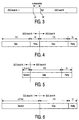
- Figure 4 shows consecutive frames for continuous recording. No special action is required.
- the recorder continually records from block N-1 to block N without special action.
- Figure 5 shows the link position for recording block N after a recorded location.
- the link position is selected at a predefined distance before the first synchronizing signal of the new frame.
- the predefined distance is relatively short (at least in the second half of the frame), but actually much closer to the end, so as to minimize the number of errors.
- the link position may be positioned after byte 178 of the last C1 code word of the previous ECC unit and before the start of the next ECC unit, i.e. the synchronizing signal Sy0.
- the data to be written before the new data start is chosen random, which is important for the interaction between old and new data for phase change recording. Writing each time exactly the same data over each other limits the amount of overwrite cycles. Therefore the following measures separate or in combination may be included :
- a distance x in error symbols (0 ⁇ x ⁇ 5) is indicated for the linking distance.
- the distance x must be shorter than the number of error symbols which can be corrected.
- the actual distance may have any value in channel bits, which results in said number of correctable symbols, as long as the spread in this distance due to linking inaccuracies does not damage the next synchronization signal Sy0. It may be acceptable that in some cases even the beginning of the Sy0 synchronizing pattern is damaged, as long as the special mark (or marks) within the synchronizing pattern, e.g. a long mark I14 of runlength 14 channel bits, is not damaged, because such special marks are used for detecting the synchronizing patterns.
- Figure 6 shows the start position for recording block N after an unrecorded location.
- the recording should start at least a few hundred channel bits before the new ECC block starts. But the longer the better because the channel electronics (e.g. a PLL/Slicer/Sync detection) needs time to adjust and synchronize.
- the channel electronics e.g. a PLL/Slicer/Sync detection
- the flywheel construction of the sync is already working. In this case random data is written, but the sync patterns are of course embedded in the proper positions.
- Figure 8 shows a short link mark at a link position.
- the synchronizing pattern 30 (Sy0, total length 32 channel bits) comprises a long I14 mark 81 with a runlength of 14 channel bits, followed by a short I4 mark 82 of 4 channel bits, and preceded by some short marks 83 (not fully shown), which synchronizing pattern is used in DVD.
- Sy0 the normal data represented by series of marks 88 follows, in which marks I3 have the minimum runlength 3, and marks I11 have the maximum runlength 11.
- the synchronizing pattern 30 cannot occur in the normal data and long mark 81 is easily recognized as synchronizing mark.
- the link position 31 is selected at 8 channel bits before the boundary 80, as described above with reference to Figure 3.
- the first mark after the link position 31 is a link mark 84, which has a runlength of 2 channel bits, i.e. shorter than the shortest mark in the normal data series of marks 88.
- the area between the link position 31 and the synchronizing pattern 30 is filled by a linking sequence, which has the link mark 84 as its first mark and a further pattern of marks 85.
- the link mark 84 may have the same polarity as existing marks of block N-1, but the maximum runlength of the resulting concatenated mark is as short as possible. Hence the occurrence of false synchronizing marks is minimized.
- the link mark is shorter than the difference between the synchronizing mark and the longest mark.
- the synchronizing mark may be set to a long runlength, e.g. I17, and for a longest normal mark of size I11, the link mark sizes I3, I4 and I5 may be used. However, to prevent errors by concatenated marks or consecutive marks with a short, undetectable interruption, the shorter link marks are preferred.
- the linking sequence may be fixed but with a random polarity, or the further pattern may be generated at random (within the runlength constraints for normal data).
- the linking sequence may be randomly or sequentially selected from a limited set of linking sequences that each start with a link mark followed by a predefined but differing number of mark boundaries. It is to be noted that the link mark now always has the same polarity, e.g. formed by write level laser power, and that following number of mark boundaries results in a random start level of the normal data. Commonly sequences of marks are indicated by binary strings, a 'one' indicating a mark boundary and a 'zero' indicating no change.
- Suitable sets of sequences for a link position at 8 channel bits are: 10100000 (resulting in the marks shown in Figure 8) and 10100100 when starting with an I2 mark, and 10010000 and 10010010 when starting with an I3 mark.
- 10100000 results in the marks shown in Figure 8
- 10100100 when starting with an I2 mark
- 10010000 and 10010010 when starting with an I3 mark.
- Each time a unit is recorded one of the linking sequences is selected, e.g. alternating.
- substantially half of the linking sequences of the set should have an odd number of mark boundaries, to achieve a random polarity of the signal at the start of Sy0.
- the mark following the link mark has a length differing of 4, whereas in the synchronizing pattern the long mark 81 is followed by the I4 mark.
- the second mark preferably is of a different length than the mark following the long mark 81 in the synchronizing pattern. This further reduces the occurrence of false synchronizing, when synchronizing detectors are arranged for detecting the combination of the long mark and a second mark of the synchronizing pattern.
- the synchronizing pattern comprises a combination of marks which does not occur in the normal data series of marks, e.g. two consecutive marks of the maximum runlength.
- the linking sequence now starts with the short link mark, followed by at least a further short mark. Hence the occurrence of false synchronizing patterns is minimized.
- the length and pattern of synchronizing marks and the linking sequence are selected to minimize or preferably exclude the occurrence of false synchronizing patterns.
- a signal element may be a pulse or a sequence of very short pulses.
- Figure 7 shows the end link position for recording block N before a recorded location.
- the next block N+1 starts with a synchronizing signal 74.
- the end link position 73 at which the writing process is stopped is preferable as short as possible before the position of the next ECC block, because then the error correction has the minimum number of errors to correct.
- the end link position may be set at the same link distance as the start link position, but alternatively a different distance may be selected, e.g. a somewhat closer to synchronizing signal 74 to prevent unrecorded areas, which might be mistaken for synchronizing marks.
- the remaining number of undamaged parity symbols x is indicated to be between 5 and 10 for example for DVD, indicating that at least half the available number is undamaged.
- the information is represented by marks of different runlengths.
- the last mark 71 before the end link position 73 is a short mark of a runlength at most as long as the minimum runlength in the rest of the ECC block.
- the link mark is followed by an intermediate area 72 up to the first synchronizing mark of the ECC block N+1, which intermediate area usually comprises old marks of previous block N.
- the link mark may be added immediately.
- first one or more intermediate marks may be added before the link mark, resulting in a link pattern up to the link position.
- the link pattern may be selected according to encoding rules required by the preceding symbols, e.g.
- the last mark has a runlength shorter than said minimum runlength.
- the short link mark 71 may be of the same polarity as the old marks and concatenate with one of them, but the maximum runlength of the resulting concatenated mark is as short as possible. Hence the occurrence of false synchronizing marks is minimized.
- additional measures are taken to achieve the short link mark, e.g. runlength I2 or I3, at the end of writing.
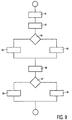
- Figure 9 shows a recording method for successively recording information signals. It is assumed that a record carrier of a writable type is inserted in a recording device and that it already contains some recorded information.
- a command is received to record block N.
- a second step 92 (SCAN) the track on the record carrier is scanned up to the preceding location of block N-1.
- a first test 93 it is decided, if the preceding location is not blank (i.e. contains already some information signal). If NOT BLANK, in a step 95 a start position is determined at a first predetermined distance as described above with reference to Figure 5.
- a step 94 a long sequence of dummy data is recorded before the start of location N to enable any read circuit to lock to the data as described with reference to Figure 6.
- step 96 after said steps 94 or 95 the actual block N (or several continuous blocks as described with reference to Figure 4) are recorded.
- test 97 the status of the location N+1 after block N is determined. This may be accomplished by scanning the track before the recording is started, e.g. in step 92. Alternatively a special table may be present on the record carrier or in the device which keeps track of unrecorded and recorded areas, e.g. in the file management system. In the event that no signal is recorded after block N (or the signal has no valid status, e.g.
- a step the recording process is continued at least until the modulated signal of block N is completely recorded, and it may be continued for some predetermined distance after the last frame to prevent any read circuit from detecting a read error prematurely.
- the recording process is stopped at a second predetermined distance before the modulated signal of block N is completely recorded as described with reference to Figure 7. After steps 98 or 99 the recording of block N is completed, and a next command may be awaited.
- test 97 is omitted and the recording process is always stopped at a short predetermined distance before the nominal position of the start of the synchronizing signal of the next block.
- the above embodiments may be arranged to select the second predetermined distance always shorter than the first predetermined distance. This has the advantageous effect, that no unrecorded gaps will exist between successively recorded blocks. It is to be noted that starting and ending point inaccuracies must be taken into account.
- the record carrier may also be a magnetic type disc or a tape.
- the word 'comprising' does not exclude the presence of other elements or steps than those listed and the word 'a' or 'an' preceding an element does not exclude the presence of a plurality of such elements, that any reference signs do not limit the scope of the claims, that the invention may be implemented by means of both hardware and software, and that several 'means' may be represented by the same item of hardware. Further, the scope of the invention is not limited to the embodiments, and the invention lies in each and every novel feature or combination of features described above.
Abstract
A method and device for recording information in units on a partly recorded
writable record carrier (11), e.g. an optical disc. The information is recorded in a track
represented by series of marks of different runlengths between a minimum runlength and a
maximum runlength and synchronizing patterns of marks, which patterns do not occur in the
series of marks and comprise at least one long mark of at least the maximum runlength. At
least one information unit is encoded into a modulated signal comprising signal elements
corresponding to said marks. The track is scanned up to a link position before a selected one of
said addressable locations, and the modulated signal is recorded from the link position. The
modulated signal is provided at the begin and/or at the end with a link signal element
corresponding to a mark of at most the minimum runlength.
Description
The invention relates to a method of recording information in units on a record
carrier having a track for consecutively recording the information units at addressable
locations, the information being represented in the track by series of marks of different
runlengths between a minimum runlength and a maximum runlength and synchronizing
patterns of marks, which patterns do not occur in the series of marks and comprise at least one
long mark of at least the maximum runlength, said method comprising encoding at least one
information unit into a modulated signal comprising signal elements corresponding to said
marks, scanning said track up to a link position before a selected one of said addressable
locations, and recording the modulated signal from the link position.
The invention further relates to a device for recording information in units on a
record carrier having a track for consecutively recording the information units at addressable
locations, the information being represented in the track by series of marks of different
runlengths between a minimum runlength and a maximum runlength and synchronizing
patterns of marks, which patterns do not occur in the series of marks and comprise at least one
long mark of at least the maximum runlength, said device comprising encoding means for
encoding at least one information unit into a modulated signal comprising signal elements
corresponding to said marks, and recording means for scanning said track up to a link position
before a selected one of said addressable locations and recording the modulated signal from
the link position.
A method and apparatus for successively recording information signals on a
record carrier is known from US 5,187,699. The information signal is modulated to a
modulated signal having a frame structure comprising synchronizing signals for positioning
the modulated signal in the track at predefined locations indicated by prerecorded track
position information. The process of consecutively recording signals in adjacent areas in a
track on the record carrier is called linking. In the known linking method, after a first
recording signal is completely recorded, the recording process is continued after the last frame
of the modulated signal up to a link position. When a next information signal is to be recorded,
the recording process is started at the link position by recording dummy information (usually
zero data) up to the start of the following predefined location. Hence the signal prior to the
first frame synchronizing signal of said following location does not contain valid information.
As a result a so called linking block is created between the first recorded signal and the second
recorded signal, which linking block includes said link position. Hence the linking block does
not contain valid recorded information, and its data storage capacity is lost.
It is an object of the invention to provide a recording method and device in
which linking is more efficient.
For this purpose, the method as described in the opening paragraph is
characterized in that the modulated signal is provided at the begin and/or at the end with a link
signal element corresponding to a link mark of at most the minimum runlength. Further the
device as described in the opening paragraph is characterized in that the encoding means are
arranged for providing the modulated signal at the begin and/or at the end with a link signal
element corresponding to a link mark of at most the minimum runlength. The effect of the link
mark is, that in combination with old data recorded in the track at the link position the link
mark may form concatenated marks which have a limited runlength, because of the short
runlength of the link mark. Hence the occurrence of unintentional long concatenated marks is
obviated. As such long marks might be interpreted as the long mark in the synchronizing
pattern, occurrence of false sync detection is opposed. Because no false sync detection occurs,
a valid synchronizing pattern in the newly recorded information shortly after the link position
is reliably detectable. Hence only a very short area around the link position is lost as storage
capacity and cannot contain valid data. A similar effect occurs at the end of the newly
recorded data. The last recorded mark may concatenate with the old marks and a resulting long
mark may falsely be detected as a synchronizing pattern, disturbing the detection of the valid
synchronizing pattern of a next information unit already recorded in the adjacent location
immediately after the newly recorded location. Using the link mark at the end of writing
obviates the occurrence of long concatenated marks.
The invention is also based on the following recognition. Usual channel coding
and decoding systems are arranged to operate on symbols (e.g. 8 or 16 channel bits). When
during decoding a read signal from the link position is decoded, the decoder will be confronted
with a shift of the symbol boundary, a so called bit slip of a few bits, because it is hardly
possible to start the recording process with an accuracy of less than one bit. As a result the
decoder will detect errors in all symbols up to the next valid synchronizing signal. In the prior
art systems at the link position a false synchronizing pattern might be created, which posed no
problem, as the linking block did not contain useful data. However the inventors have seen,
that by preventing false detection of synchronizing patterns the unusable storage area after the
linking area can be limited. Any next valid synchronizing signal can be detected reliably,
because there is substantially no risk that the synchronizing detector locks on a false
synchronizing pattern.
A preferred embodiment of the device according to claim 4 has the advantage,
that the link mark is so short, that even if concatenated to a maximum runlength mark, the
longest concatenated mark is limited. In particular this is advantageous, if the long mark in the
synchronizing pattern is longer than said longest concatenated mark.
Further advantageous, preferred embodiments according to the invention are
given in the further dependent claims.
These and other aspects of the invention will be apparent from and elucidated
further with reference to the embodiments described by way of example in the following
description and with reference to the accompanying drawings, in which
Figure 1a shows a disc-shaped record carrier 11 having a track 9 and a central
hole 10. The track 9 is arranged in accordance with a spiral pattern of turns constituting
substantially parallel tracks on an information layer. The record carrier may be optically
readable, called an optical disc, and has an information layer of a recordable type. Examples of
a recordable disc are the CD-R and CD-RW, and writable versions of DVD, such as
DVD+RW. The information is represented on the information layer by recording optically
detectable marks along the track, e.g. crystalline or amorphous marks in phase change
material. The track 9 on the recordable type of record carrier is indicated by a pre-embossed
track structure provided during manufacture of the blank record carrier. The track structure is
constituted, for example, by a pregroove 14 which enables a read/write head to follow the
track during scanning. The track structure comprises position information, e.g. addresses, for
indication the location of units of information, usually called blocks. The position information
may include specific synchronizing marks for locating the start of such units.
Figure 1b is a cross-section taken along the line b-b of the record carrier 11 of
the recordable type, in which a transparent substrate 15 is provided with a recording layer 16
and a protective layer 17. The pregroove 14 may be implemented as an indentation or an
elevation, or as a material property deviating from its surroundings.
The record carrier 11 is intended for carrying information represented by
modulated signals comprising frames. A frame is a predefined amount of data preceded by a
synchronizing signal. Usually such frames also comprise error correction codes, e.g. parity
words. An example of such a recording system is known from the DVD system, in which the
frames carry 172 data words and 10 parity words, which example is used in the description
below. The data is organized in units comprising a number of frames which contain Error
Correction Codes (ECC) for correcting errors in the user information in the unit. In DVD the
size of such a unit is 32KB user data, and contains 2 layers of error correction, and is called a
block. The first layer of error correction (called C1) corrects small errors like random errors,
and the second layer (called C2) corrects the large error such as burst errors. A drive should
be able to write and/or rewrite such a block independently. According to the invention no
blocks are needed for linking only, all blocks can be used to store user data. This means that a
link position should be defined in order to guarantee data integrity. There will always be some
errors on a link position but the goal is to minimize the amount of errors on such a link
position. The following items are important for the choice of the link position:
- The accuracy of the writing (in channel bits) which can be achieved with respect to the data already written on the disc.
- The effect of a few bit errors on the error correction.
- The content of the data written on the link position.
- The physical damage caused by overwriting each time the same data.
Figure 3 shows the link position due to recording block N after block N-1. The
link position 31 is indicated by a dashed line at 'n' channel bits before the synchronizing
signal 30, in the DVD format called Sy0. For DVD the first error correction layer consists of
172 data bytes and 10 parity bytes. With 10 parity bytes maximum 5 byte errors can be
corrected, but a more practical limit is less or equal to 4 byte errors. The result of this insight is
to position the linking of ECC block N-1 and ECC block N after the last 4 bytes of ECC block
N-1 and before the start of block N. For n = 32 the position shown corresponds to 2 bytes (as
one byte has 16 channel bits in DVD), which gives the maximum tolerance for link position
inaccuracies. In general the link position may be selected as close as possible before the
synchronization signal, while making sure that despite the start of write link position
inaccuracies in forward direction the new information always overwrites the old
synchronization signal. Correspondingly, at the end of write before an already existing
information unit, the new information should never damage the next synchronization signal of
said already existing information unit. The last channel words of an information unit usually
represent parity symbols (called parity bytes above), and hence the minimal number of parity
symbols is damaged. In an embodiment the linking errors can be limited to errors within one
symbol, when the total range of link position inaccuracies in forward and backward direction
is smaller than one channel word. The link position is then set within the last channel word
before the synchronizing signal, taking into account the maximal forward and backward
inaccuracies. A practical value for such a link position is the middle of the last channel word,
when a symmetrical pattern of forward and backward link position inaccuracies is expected.
For a channel word of 16 channel bits this amounts to 8 channel bits before the end of the
information unit.
Figure 2 shows a recording device for writing information on a record carrier 11
of a type which is (re)writable. The device is provided with recording means for scanning the
track on the record carrier including drive means 21 for rotating the record carrier 11, a head
22, positioning means 25 for coarsely positioning the head 22 in the radial direction on the
track, and a control unit 20. The head 22 comprises an optical system of a known type for
generating a radiation beam 24 guided through optical elements focused to a radiation spot 23
on a track of the information layer of the record carrier. The radiation beam 24 is generated by
a radiation source, e.g. a laser diode. The head further comprises a focusing actuator for
moving the focus of the radiation beam 24 along the optical axis of said beam and a tracking
actuator for fine positioning of the spot 23 in a radial direction on the center of the track. The
tracking actuator may comprise coils for radially moving an optical element or may be
arranged for changing the angle of a reflecting element. For writing information the radiation
is controlled to create optically detectable marks in the recording layer. For reading the
radiation reflected by the information layer is detected by a detector of a usual type, e.g. a
four-quadrant diode, in the head 22 for generating a read signal and further detector signals
including a tracking error and a focusing error signal coupled to said tracking and focusing
actuators. The read signal is processed by a reading means of a usual type (not shown) to
retrieve the information. The device comprises means for processing the input information to
generate a write signal to drive the head 22, which comprise an input unit 27, a formatting unit
28, and a modulation unit 29. The control unit 20 controls the recording and retrieving of
information and may be arranged for receiving commands from a user or from a host
computer. The control unit 20 is connected via control lines 26, e.g. a system bus, to said
means and to the drive means 21, and the positioning means 25. The control unit 20 comprises
control circuitry, for example a microprocessor, a program memory and control gates, for
performing the procedures and functions according to the invention as described below with
reference to Figure 3. The control unit 20 may also be implemented as a state machine in logic
circuits. During the writing operation, marks representing the information are formed on the
record carrier. The marks may be in any optically readable form, e.g. in the form of areas with
a reflection coefficient different from their surroundings, obtained when recording in materials
such as dye, alloy or phase change material, or in the form of areas with a direction of
magnetization different from their surroundings, obtained when recording in magneto-optical
material. Writing and reading of information for recording on optical disks and usable
formatting, error correcting and channel coding rules are well-known in the art, e.g. from the
CD system. The marks can be formed by means of the spot 23 generated on the recording
layer via the beam 24 of electromagnetic radiation, usually from a laser diode. User
information is presented on the input unit 27, which may comprise of compression means for
input signals such as analog audio and/or video, or digital uncompressed audio/video. Suitable
compression means are described for audio in WO 98/16014-A1 (PHN 16452) and for video
in the MPEG2 standard. The input unit 27 processes the audio and/or video to unit of
information, which are passed to the formatting unit 28 for adding control data and formatting
the data according to the recording format, e.g. by adding error correction codes (ECC). For
computer applications units of information may be interfaced to the formatting unit 28
directly. The formatted data from the output of the formatting unit 28 is passed to the
modulation unit 29, which comprises for example a channel coder, for generating a modulated
signal which drives the head 22. Further the modulation unit 29 comprises synchronizing
means for including synchronizing patterns in the modulated signal. The formatted units
presented to the input of the modulation unit 29 comprise address information and are written
to corresponding addressable locations on the record carrier under the control of control unit
20. Usually the recording apparatus will also be arranged for reading having the reading and
decoding means of a playback apparatus and a combined write/read head.
According to the invention the control unit 20 of the recording device as shown
in Figure 2 is arranged for recording the information according to the methods described
below with reference to the Figures 4 to 8. The modes of writing are defined for different
situations. The start/stop or continuous writing modes are defined separately; four different
writing modes are defined: Continuous writing, Start of writing when the previous location is
already written, Start of writing when the previous location is erased or not written, and
End of writing.
Figure 4 shows consecutive frames for continuous recording. No special action
is required. The recorder continually records from block N-1 to block N without special
action.
Figure 5 shows the link position for recording block N after a recorded location.
The link position is selected at a predefined distance before the first synchronizing signal of
the new frame. The predefined distance is relatively short (at least in the second half of the
frame), but actually much closer to the end, so as to minimize the number of errors. For
recording DVD the link position may be positioned after byte 178 of the last C1 code word of
the previous ECC unit and before the start of the next ECC unit, i.e. the synchronizing signal
Sy0. In an embodiment the data to be written before the new data start is chosen random,
which is important for the interaction between old and new data for phase change recording.
Writing each time exactly the same data over each other limits the amount of overwrite cycles.
Therefore the following measures separate or in combination may be included :
- The data in the linking area can be chosen random. This will prevent overwriting each time the same data in the linking area. An advantage of using random data is important when the new ECC unit contains always exactly the same data. The random data will cause always of different start value of the Digital Sum Value (DSV) at the beginning of the new ECC unit. The different values of the DSV cause differences in the following signal even when the data is not changed, and this improves the number of overwrite cycles of the data.
- A small random shift of the link position can be introduced to improve the direct overwrite cycles.
In Figure 5 a distance x in error symbols (0 < x < 5) is indicated for the linking
distance. As discussed above the distance x must be shorter than the number of error symbols
which can be corrected. Of course the actual distance may have any value in channel bits,
which results in said number of correctable symbols, as long as the spread in this distance due
to linking inaccuracies does not damage the next synchronization signal Sy0. It may be
acceptable that in some cases even the beginning of the Sy0 synchronizing pattern is damaged,
as long as the special mark (or marks) within the synchronizing pattern, e.g. a long mark I14
of runlength 14 channel bits, is not damaged, because such special marks are used for
detecting the synchronizing patterns.
Figure 6 shows the start position for recording block N after an unrecorded
location. When no data is written on the disc at the position of the previous ECC block then
the recording should start at least a few hundred channel bits before the new ECC block starts.
But the longer the better because the channel electronics (e.g. a PLL/Slicer/Sync detection)
needs time to adjust and synchronize. When at least 3 three sync frames are recorded then the
flywheel construction of the sync is already working. In this case random data is written, but
the sync patterns are of course embedded in the proper positions.
Figure 8 shows a short link mark at a link position. A schematic drawing of
marks around the boundary 80 between two locations 'ECC block N-1' and 'ECC block N' is
drawn. The synchronizing pattern 30 (Sy0, total length 32 channel bits) comprises a long I14
mark 81 with a runlength of 14 channel bits, followed by a short I4 mark 82 of 4 channel bits,
and preceded by some short marks 83 (not fully shown), which synchronizing pattern is used
in DVD. After Sy0 the normal data represented by series of marks 88 follows, in which marks
I3 have the minimum runlength 3, and marks I11 have the maximum runlength 11. Hence the
synchronizing pattern 30 cannot occur in the normal data and long mark 81 is easily
recognized as synchronizing mark. The link position 31 is selected at 8 channel bits before the
boundary 80, as described above with reference to Figure 3. The first mark after the link
position 31 is a link mark 84, which has a runlength of 2 channel bits, i.e. shorter than the
shortest mark in the normal data series of marks 88. The area between the link position 31 and
the synchronizing pattern 30 is filled by a linking sequence, which has the link mark 84 as its
first mark and a further pattern of marks 85. The link mark 84 may have the same polarity as
existing marks of block N-1, but the maximum runlength of the resulting concatenated mark is
as short as possible. Hence the occurrence of false synchronizing marks is minimized.
In an embodiment the link mark is shorter than the difference between the
synchronizing mark and the longest mark. The synchronizing mark may be set to a long
runlength, e.g. I17, and for a longest normal mark of size I11, the link mark sizes I3, I4 and I5
may be used. However, to prevent errors by concatenated marks or consecutive marks with a
short, undetectable interruption, the shorter link marks are preferred. In Figure 8 the link mark
has length I2, which is one channel bit shorter than the shortest mark in the normal data, and
also shorter than the difference between the longest mark I11 and the long synchronizing mark
81 with length I14, i.e. I14 - II11 = 3.
As described with reference to Figure 5 the signals written at a same location
are not the same each time. In an embodiment the linking sequence may be fixed but with a
random polarity, or the further pattern may be generated at random (within the runlength
constraints for normal data). In an embodiment the linking sequence may be randomly or
sequentially selected from a limited set of linking sequences that each start with a link mark
followed by a predefined but differing number of mark boundaries. It is to be noted that the
link mark now always has the same polarity, e.g. formed by write level laser power, and that
following number of mark boundaries results in a random start level of the normal data.
Commonly sequences of marks are indicated by binary strings, a 'one' indicating a mark
boundary and a 'zero' indicating no change. Suitable sets of sequences for a link position at 8
channel bits are: 10100000 (resulting in the marks shown in Figure 8) and 10100100 when
starting with an I2 mark, and 10010000 and 10010010 when starting with an I3 mark. Each
time a unit is recorded one of the linking sequences is selected, e.g. alternating. For such sets
substantially half of the linking sequences of the set should have an odd number of mark
boundaries, to achieve a random polarity of the signal at the start of Sy0.
In an embodiment for DVD the mark following the link mark has a length
differing of 4, whereas in the synchronizing pattern the long mark 81 is followed by the I4
mark. In general in the linking sequences the second mark preferably is of a different length
than the mark following the long mark 81 in the synchronizing pattern. This further reduces
the occurrence of false synchronizing, when synchronizing detectors are arranged for detecting
the combination of the long mark and a second mark of the synchronizing pattern. In a further
embodiment the synchronizing pattern comprises a combination of marks which does not
occur in the normal data series of marks, e.g. two consecutive marks of the maximum
runlength. The linking sequence now starts with the short link mark, followed by at least a
further short mark. Hence the occurrence of false synchronizing patterns is minimized. In the
embodiments of a recording device the length and pattern of synchronizing marks and the
linking sequence are selected to minimize or preferably exclude the occurrence of false
synchronizing patterns.
The above marks are recorded in the track according to known recording
methods by driving a write head by a modulated signal that has signal elements corresponding
to the marks, as described with reference to Figure 2. For example a signal element may be a
pulse or a sequence of very short pulses.
Figure 7 shows the end link position for recording block N before a recorded
location. The next block N+1 starts with a synchronizing signal 74. The end link position 73 at
which the writing process is stopped is preferable as short as possible before the position of
the next ECC block, because then the error correction has the minimum number of errors to
correct. The end link position may be set at the same link distance as the start link position, but
alternatively a different distance may be selected, e.g. a somewhat closer to synchronizing
signal 74 to prevent unrecorded areas, which might be mistaken for synchronizing marks. The
remaining number of undamaged parity symbols x is indicated to be between 5 and 10 for
example for DVD, indicating that at least half the available number is undamaged. The
information is represented by marks of different runlengths. Advantageously the last mark 71
before the end link position 73, called link mark, is a short mark of a runlength at most as long
as the minimum runlength in the rest of the ECC block. The link mark is followed by an
intermediate area 72 up to the first synchronizing mark of the ECC block N+1, which
intermediate area usually comprises old marks of previous block N. After the last (completely
written) parity symbol, e.g. x = 9, the link mark may be added immediately. Alternatively, first
one or more intermediate marks may be added before the link mark, resulting in a link pattern
up to the link position. The link pattern may be selected according to encoding rules required
by the preceding symbols, e.g. in the channel encoding rules of DVD some bit positions in a
channel word are required for decoding the preceding code word via a so called coding state.
Hence the corresponding bit positions in the link pattern must be according to the required
coding state, and the last undamaged parity symbol may be decoded unambiguously. In an
embodiment the last mark has a runlength shorter than said minimum runlength. The short link
mark 71 may be of the same polarity as the old marks and concatenate with one of them, but
the maximum runlength of the resulting concatenated mark is as short as possible. Hence the
occurrence of false synchronizing marks is minimized. In an embodiment additional measures
are taken to achieve the short link mark, e.g. runlength I2 or I3, at the end of writing. Usually
(in phase change recording) after writing a mark by a writing laser power level the laser is
switched to erasing power to create the next mark, i.e. an erased area of the required runlength.
However, because of the substantially circular shape of the spot 23 on the recording layer, the
last part of the preceding written mark is also erased, resulting in a concave, roughly moon
shaped, ending of the preceding mark. Hence, when the writing is stopped after the link mark,
and consequently the laser is switched off or at most to reading power, no erasing effect of
said last part occurs, and the link mark tends to be longer than intended. To compensate this
prolonging effect, a shorter (e.g. I2) link mark may be used at stopping, whereas a somewhat
longer (e.g. I3) link mark may be used at the start of write. Alternatively, a dedicated write
pulse sequence may be used for the stopping link mark, e.g. using the normal I2 pulse
followed by a very short erasing pulse.
Figure 9 shows a recording method for successively recording information
signals. It is assumed that a record carrier of a writable type is inserted in a recording device
and that it already contains some recorded information. In a first step 91 (COMMAND) a
command is received to record block N. In a second step 92 (SCAN) the track on the record
carrier is scanned up to the preceding location of block N-1. In a first test 93 it is decided, if
the preceding location is not blank (i.e. contains already some information signal). If NOT
BLANK, in a step 95 a start position is determined at a first predetermined distance as
described above with reference to Figure 5. If no information signal is present on the
preceding location, in a step 94 a long sequence of dummy data is recorded before the start of
location N to enable any read circuit to lock to the data as described with reference to Figure 6.
In step 96 after said steps 94 or 95 the actual block N (or several continuous blocks as
described with reference to Figure 4) are recorded. In test 97 the status of the location N+1
after block N is determined. This may be accomplished by scanning the track before the
recording is started, e.g. in step 92. Alternatively a special table may be present on the record
carrier or in the device which keeps track of unrecorded and recorded areas, e.g. in the file
management system. In the event that no signal is recorded after block N (or the signal has no
valid status, e.g. erased), in a step the recording process is continued at least until the
modulated signal of block N is completely recorded, and it may be continued for some
predetermined distance after the last frame to prevent any read circuit from detecting a read
error prematurely. In the event that the next location N+1 contains a valid information signal,
in a step 99 the recording process is stopped at a second predetermined distance before the
modulated signal of block N is completely recorded as described with reference to Figure 7.
After steps 98 or 99 the recording of block N is completed, and a next command may be
awaited.
In an embodiment the test 97 is omitted and the recording process is always
stopped at a short predetermined distance before the nominal position of the start of the
synchronizing signal of the next block. In addition the above embodiments may be arranged to
select the second predetermined distance always shorter than the first predetermined distance.
This has the advantageous effect, that no unrecorded gaps will exist between successively
recorded blocks. It is to be noted that starting and ending point inaccuracies must be taken into
account.
Although the invention has been explained by embodiments using the DVD-optical
recording format, it may be applied for any format for recording units of information.
For example the record carrier may also be a magnetic type disc or a tape. It is noted, that in
this document the word 'comprising' does not exclude the presence of other elements or steps
than those listed and the word 'a' or 'an' preceding an element does not exclude the presence
of a plurality of such elements, that any reference signs do not limit the scope of the claims,
that the invention may be implemented by means of both hardware and software, and that
several 'means' may be represented by the same item of hardware. Further, the scope of the
invention is not limited to the embodiments, and the invention lies in each and every novel
feature or combination of features described above.
Claims (9)
- Method of recording information in units on a record carrier having a track for consecutively recording the information units at addressable locations, the information being represented in the track by series of marks of different runlengths between a minimum runlength and a maximum runlength and synchronizing patterns of marks, which patterns do not occur in the series of marks and comprise at least one long mark of at least the maximum runlength, said method comprising:characterized in that(a) encoding at least one information unit into a modulated signal comprising signal elements corresponding to said marks,(b) scanning said track up to a link position before a selected one of said addressable locations, and(c) recording the modulated signal from the link position,
(d) the modulated signal is provided at the begin and/or at the end with a link signal element corresponding to a link mark of at most the minimum runlength. - Method as claimed in claim 1, wherein the link signal element corresponds to a mark shorter than the minimum runlength.
- Device for recording information in units on a record carrier (11) having a track (9) for consecutively recording the information units at addressable locations, the information being represented in the track (9) by series of marks of different runlengths between a minimum runlength and a maximum runlength and synchronizing patterns (30) of marks, which patterns do not occur in the series of marks and comprise at least one long mark (81) of at least the maximum runlength, said device comprising encoding means (28,29) for encoding at least one information unit into a modulated signal comprising signal elements corresponding to said marks, and recording means (20,21,22,25) for scanning said track up to a link position before a selected one of said addressable locations and recording the modulated signal from the link position, characterized in that
the encoding means (28,29) are arranged for providing the modulated signal at the begin and/or at the end with a link signal element corresponding to a link mark (84) of at most the minimum runlength. - Device as claimed in claim 3, wherein said runlengths are expressed in steps of a channel bit, and the encoding means (28,29) are arranged for providing the link signal element corresponding to a link mark (84) one channel bit shorter than the minimum runlength.
- Device as claimed in claim 3 or 4, wherein the encoding means comprise synchronizing means (29) for providing said at least one long mark (81) in the synchronizing pattern (30) at a runlength longer than the sum of the maximum runlength and the runlength of the link mark (84).
- Device as claimed in claim 3, wherein the encoding means (28,29) comprise synchronizing means (29) for providing the synchronizing pattern (30) having said at least one long mark (81) followed by a short mark (82) of a runlength shorter than the maximum runlength, and the encoding means (28,29) are arranged for providing a second link signal element after the link signal element at the begin of the modulated signal, the second link signal element corresponding to a mark (85) differing from the short mark (82).
- Device as claimed in claim 3, wherein the encoding means (28,29) comprise means (28) for variably selecting one out of a set of fixed linking sequences that each start with the link signal element followed by further signal elements for recording marks up to the first synchronizing pattern, substantially half of the linking sequences of the set having an odd number of mark boundaries.
- Device as claimed in claim 7, wherein the linking sequences have a fixed length of 8 channel bits, and the set of fixed linking sequences comprises 10100000 and 10100100, or 10010000 and 10010010, each 1 indicating a mark boundary.
- Device as claimed in claim 3, wherein the device comprises means (27) for processing or compressing digital or analog input signals such as audio and/or video to units of information.
Priority Applications (18)
| Application Number | Priority Date | Filing Date | Title |
|---|---|---|---|
| EP99201185A EP1045391A1 (en) | 1999-04-16 | 1999-04-16 | Method and device for recording information in units |
| TW089105691A TW546635B (en) | 1999-04-16 | 2000-03-28 | Method and device for recording information in units |
| AT00931051T ATE335275T1 (en) | 1999-04-16 | 2000-03-29 | METHOD AND DEVICE FOR RECORDING INFORMATION IN UNITS |
| PT00931051T PT1088308E (en) | 1999-04-16 | 2000-03-29 | Method and device for recording information in units |
| HU0103323A HU225085B1 (en) | 1999-04-16 | 2000-03-29 | Method and device for recording information in units |
| JP2000612951A JP4208417B2 (en) | 1999-04-16 | 2000-03-29 | Method and apparatus for recording information in units |
| BRPI0006043-7A BR0006043B1 (en) | 1999-04-16 | 2000-03-29 | process and device for writing unit information about a recording carrier. |
| EP00931051A EP1088308B1 (en) | 1999-04-16 | 2000-03-29 | Method and device for recording information in units |
| PL344870A PL201769B1 (en) | 1999-04-16 | 2000-03-29 | Method and device for recording information in units |
| RU2001101532/28A RU2242055C2 (en) | 1999-04-16 | 2000-03-29 | Method and device for recording elements of information |
| CNB008005990A CN1213427C (en) | 1999-04-16 | 2000-03-29 | Method and device for recording infor mation in units |
| ES00931051T ES2269145T3 (en) | 1999-04-16 | 2000-03-29 | METHOD AND DEVICE FOR RECORDING INFORMATION IN UNITS. |
| DE60029716T DE60029716T2 (en) | 1999-04-16 | 2000-03-29 | METHOD AND DEVICE FOR INFORMATION RECORDING IN UNITS |
| KR1020007014163A KR100606867B1 (en) | 1999-04-16 | 2000-03-29 | Method and device for recording information in units |
| PCT/EP2000/002791 WO2000063908A1 (en) | 1999-04-16 | 2000-03-29 | Method and device for recording information in units |
| ARP000101611A AR023418A1 (en) | 1999-04-16 | 2000-04-07 | METHOD AND DEVICE FOR RECORDING INFORMATION IN UNITS. |
| US09/546,971 US7038991B1 (en) | 1999-04-16 | 2000-04-11 | Method and device for recording information in units |
| MYPI20001574A MY130220A (en) | 1999-04-16 | 2000-04-13 | Method and device for recording information in units |
Applications Claiming Priority (1)
| Application Number | Priority Date | Filing Date | Title |
|---|---|---|---|
| EP99201185A EP1045391A1 (en) | 1999-04-16 | 1999-04-16 | Method and device for recording information in units |
Publications (1)
| Publication Number | Publication Date |
|---|---|
| EP1045391A1 true EP1045391A1 (en) | 2000-10-18 |
Family
ID=8240103
Family Applications (2)
| Application Number | Title | Priority Date | Filing Date |
|---|---|---|---|
| EP99201185A Withdrawn EP1045391A1 (en) | 1999-04-16 | 1999-04-16 | Method and device for recording information in units |
| EP00931051A Expired - Lifetime EP1088308B1 (en) | 1999-04-16 | 2000-03-29 | Method and device for recording information in units |
Family Applications After (1)
| Application Number | Title | Priority Date | Filing Date |
|---|---|---|---|
| EP00931051A Expired - Lifetime EP1088308B1 (en) | 1999-04-16 | 2000-03-29 | Method and device for recording information in units |
Country Status (17)
| Country | Link |
|---|---|
| US (1) | US7038991B1 (en) |
| EP (2) | EP1045391A1 (en) |
| JP (1) | JP4208417B2 (en) |
| KR (1) | KR100606867B1 (en) |
| CN (1) | CN1213427C (en) |
| AR (1) | AR023418A1 (en) |
| AT (1) | ATE335275T1 (en) |
| BR (1) | BR0006043B1 (en) |
| DE (1) | DE60029716T2 (en) |
| ES (1) | ES2269145T3 (en) |
| HU (1) | HU225085B1 (en) |
| MY (1) | MY130220A (en) |
| PL (1) | PL201769B1 (en) |
| PT (1) | PT1088308E (en) |
| RU (1) | RU2242055C2 (en) |
| TW (1) | TW546635B (en) |
| WO (1) | WO2000063908A1 (en) |
Cited By (11)
| Publication number | Priority date | Publication date | Assignee | Title |
|---|---|---|---|---|
| WO2002031818A2 (en) * | 2000-10-12 | 2002-04-18 | Koninklijke Philips Electronics N.V. | Method and device for recording information in units |
| WO2002052558A2 (en) * | 2000-12-26 | 2002-07-04 | Pioneer Corporation | Information recording/reproducing apparatus, and information recording medium with linking blocks |
| EP1239477A2 (en) * | 2001-03-09 | 2002-09-11 | LG Electronics Inc. | Read-only recording medium and a reproducing method thereof |
| WO2003010765A2 (en) * | 2001-07-23 | 2003-02-06 | Koninklijke Philips Electronics N.V. | Method and apparatus for encoding data bits |
| WO2003083847A1 (en) | 2002-03-29 | 2003-10-09 | Samsung Electronics Co., Ltd. | Optical disk and method of recording data to the same |
| WO2004053870A1 (en) * | 2002-12-10 | 2004-06-24 | Samsung Electronics Co., Ltd. | Information storage medium and method of recording/reproducing the same |
| EP1506545A1 (en) * | 2002-05-20 | 2005-02-16 | Samsung Electronics Co., Ltd. | Optical disc and method for recording data on the same |
| EP1550111A1 (en) * | 2003-03-13 | 2005-07-06 | Samsung Electronics Co., Ltd. | Recording method, protecting method, information storage medium, and reproducing apparatus |
| US7215616B2 (en) | 2001-09-06 | 2007-05-08 | Koninklijke Philips Electronics N.V. | Method and device for running optimum power control |
| US7525889B2 (en) | 2002-06-05 | 2009-04-28 | Lg Electronics Inc. | Recording medium with a linking area including dummy data thereon and apparatus and methods for forming, recording, and reproducing the recording medium |
| US7542405B2 (en) | 2002-06-05 | 2009-06-02 | Lg Electronics Inc. | High-density optical disc, method for recording and reproducing encrypted data thereon |
Families Citing this family (8)
| Publication number | Priority date | Publication date | Assignee | Title |
|---|---|---|---|---|
| EP1324336A4 (en) * | 2000-10-02 | 2007-07-25 | Matsushita Electric Ind Co Ltd | Record medium, its recorder, its recording method, its reproducing apparatus, and its reproducing apparatus |
| JP3889365B2 (en) * | 2002-08-12 | 2007-03-07 | パイオニア株式会社 | OPTICAL RECORDING MEDIUM, RECORDING DEVICE, RECORDING METHOD, AND OPTICAL RECORDING MEDIUM MANUFACTURING METHOD |
| KR100953637B1 (en) | 2003-07-07 | 2010-04-20 | 엘지전자 주식회사 | Optical disc and recording method of Disc Information of optical disc |
| JP4158717B2 (en) * | 2004-02-16 | 2008-10-01 | ソニー株式会社 | Data recording / reproducing apparatus, data recording / reproducing method, program, and recording medium |
| JP4610607B2 (en) | 2004-03-18 | 2011-01-12 | エルジー エレクトロニクス インコーポレイティド | Method and apparatus for recording / reproducing data on / from a recording medium |
| KR101027402B1 (en) * | 2004-11-16 | 2011-04-11 | 주식회사 히타치엘지 데이터 스토리지 코리아 | Method for controlling servo for blank disk |
| JP2007280443A (en) * | 2006-04-03 | 2007-10-25 | Fuji Xerox Co Ltd | Data processor and data processing method, and program |
| JP6395380B2 (en) * | 2014-01-07 | 2018-09-26 | キヤノン株式会社 | Information processing apparatus, information processing method, and program |
Citations (6)
| Publication number | Priority date | Publication date | Assignee | Title |
|---|---|---|---|---|
| US5187699A (en) * | 1988-01-22 | 1993-02-16 | U.S. Philips Corporation | Method and apparatus for successively recording two EFM-modulated signals enabling detection of boundary condition for transitioning between signals |
| US5222086A (en) * | 1989-12-29 | 1993-06-22 | Laboratoire Europeen De Recherches Electroniques Avancees Societe En Nom Collectif | Method for the linking of data during the recording of encoded data on a recordable type optical disk |
| US5515212A (en) * | 1990-11-09 | 1996-05-07 | Insite Peripherals, Inc. | Very high-density diskette format method and computer implemented process |
| EP0718831A2 (en) * | 1994-12-20 | 1996-06-26 | Matsushita Electric Industrial Co., Ltd | Recording and reproducing method of optical information recording medium |
| EP0779623A2 (en) * | 1995-12-05 | 1997-06-18 | Kabushiki Kaisha Toshiba | Digital data transmitting method |
| EP0813198A2 (en) * | 1996-06-13 | 1997-12-17 | Sony Corporation | Recording and reproduction apparatus and method, and disk |
Family Cites Families (5)
| Publication number | Priority date | Publication date | Assignee | Title |
|---|---|---|---|---|
| EP0764327B1 (en) * | 1995-04-04 | 2001-05-09 | Matsushita Electric Industrial Co., Ltd. | Recording medium, recording method and apparatus, and reproduction method and apparatus |
| EP0880129B1 (en) * | 1996-02-08 | 2000-12-27 | Matsushita Electric Industrial Co., Ltd. | Optical disk, optical disk device, and method of reproducing information on optical disk |
| JP3824701B2 (en) * | 1996-04-01 | 2006-09-20 | パイオニア株式会社 | Information recording method and apparatus |
| US6269338B1 (en) * | 1996-10-10 | 2001-07-31 | U.S. Philips Corporation | Data compression and expansion of an audio signal |
| JP3972348B2 (en) * | 1997-07-02 | 2007-09-05 | ソニー株式会社 | Information recording / reproducing apparatus and method, and transmission medium |
-
1999
- 1999-04-16 EP EP99201185A patent/EP1045391A1/en not_active Withdrawn
-
2000
- 2000-03-28 TW TW089105691A patent/TW546635B/en not_active IP Right Cessation
- 2000-03-29 EP EP00931051A patent/EP1088308B1/en not_active Expired - Lifetime
- 2000-03-29 JP JP2000612951A patent/JP4208417B2/en not_active Expired - Fee Related
- 2000-03-29 ES ES00931051T patent/ES2269145T3/en not_active Expired - Lifetime
- 2000-03-29 HU HU0103323A patent/HU225085B1/en not_active IP Right Cessation
- 2000-03-29 PT PT00931051T patent/PT1088308E/en unknown
- 2000-03-29 PL PL344870A patent/PL201769B1/en unknown
- 2000-03-29 AT AT00931051T patent/ATE335275T1/en active
- 2000-03-29 WO PCT/EP2000/002791 patent/WO2000063908A1/en active IP Right Grant
- 2000-03-29 KR KR1020007014163A patent/KR100606867B1/en not_active IP Right Cessation
- 2000-03-29 CN CNB008005990A patent/CN1213427C/en not_active Expired - Fee Related
- 2000-03-29 BR BRPI0006043-7A patent/BR0006043B1/en not_active IP Right Cessation
- 2000-03-29 DE DE60029716T patent/DE60029716T2/en not_active Expired - Lifetime
- 2000-03-29 RU RU2001101532/28A patent/RU2242055C2/en not_active IP Right Cessation
- 2000-04-07 AR ARP000101611A patent/AR023418A1/en not_active Application Discontinuation
- 2000-04-11 US US09/546,971 patent/US7038991B1/en not_active Expired - Fee Related
- 2000-04-13 MY MYPI20001574A patent/MY130220A/en unknown
Patent Citations (6)
| Publication number | Priority date | Publication date | Assignee | Title |
|---|---|---|---|---|
| US5187699A (en) * | 1988-01-22 | 1993-02-16 | U.S. Philips Corporation | Method and apparatus for successively recording two EFM-modulated signals enabling detection of boundary condition for transitioning between signals |
| US5222086A (en) * | 1989-12-29 | 1993-06-22 | Laboratoire Europeen De Recherches Electroniques Avancees Societe En Nom Collectif | Method for the linking of data during the recording of encoded data on a recordable type optical disk |
| US5515212A (en) * | 1990-11-09 | 1996-05-07 | Insite Peripherals, Inc. | Very high-density diskette format method and computer implemented process |
| EP0718831A2 (en) * | 1994-12-20 | 1996-06-26 | Matsushita Electric Industrial Co., Ltd | Recording and reproducing method of optical information recording medium |
| EP0779623A2 (en) * | 1995-12-05 | 1997-06-18 | Kabushiki Kaisha Toshiba | Digital data transmitting method |
| EP0813198A2 (en) * | 1996-06-13 | 1997-12-17 | Sony Corporation | Recording and reproduction apparatus and method, and disk |
Cited By (46)
| Publication number | Priority date | Publication date | Assignee | Title |
|---|---|---|---|---|
| WO2002031818A3 (en) * | 2000-10-12 | 2002-07-04 | Koninkl Philips Electronics Nv | Method and device for recording information in units |
| WO2002031818A2 (en) * | 2000-10-12 | 2002-04-18 | Koninklijke Philips Electronics N.V. | Method and device for recording information in units |
| US7484163B2 (en) | 2000-12-26 | 2009-01-27 | Pioneer Corporation | Information recording/reproducing apparatus, and information recording medium |
| WO2002052558A2 (en) * | 2000-12-26 | 2002-07-04 | Pioneer Corporation | Information recording/reproducing apparatus, and information recording medium with linking blocks |
| US8190978B2 (en) | 2000-12-26 | 2012-05-29 | Pioneer Corporation | Information recording/reproducing apparatus, and information recording medium |
| US8020076B2 (en) | 2000-12-26 | 2011-09-13 | Pioneer Corporation | Information recording/reproducing apparatus, and information recording medium |
| WO2002052558A3 (en) * | 2000-12-26 | 2003-12-31 | Pioneer Corp | Information recording/reproducing apparatus, and information recording medium with linking blocks |
| US7512866B2 (en) | 2000-12-26 | 2009-03-31 | Pioneer Corporation | Information recording/reproducing apparatus, and information recording medium |
| US7266753B2 (en) | 2000-12-26 | 2007-09-04 | Pioneer Corporation | Information recording/reproducing apparatus, and information recording medium |
| US7484164B2 (en) | 2000-12-26 | 2009-01-27 | Pioneer Corporation | Information recording/reproducing apparatus, and information recording medium |
| US7480849B2 (en) | 2000-12-26 | 2009-01-20 | Pioneer Corporation | Information recording/reproducing apparatus, and information recording medium |
| EP1833053A3 (en) * | 2000-12-26 | 2012-08-01 | Pioneer Corporation | Information recording/reproducing apparatus, and information recording medium |
| US7415650B2 (en) | 2000-12-26 | 2008-08-19 | Pioneer Corporation | Information recording/reproducing apparatus, and information recording medium |
| US7404135B2 (en) | 2000-12-26 | 2008-07-22 | Pioneer Corporation | Information recording/reproducing apparatus, and information recording medium |
| EP1818928A3 (en) * | 2000-12-26 | 2008-06-04 | Pioneer Corporation | Information recording/reproducing apparatus, and information recording medium |
| EP1818925A3 (en) * | 2000-12-26 | 2008-04-02 | Pioneer Corporation | Information recording/reproducing apparatus, and information recording medium |
| EP1686583A3 (en) * | 2000-12-26 | 2008-01-23 | Pioneer Corporation | Information recording/reproducing apparatus, and information recording medium |
| EP1833054A2 (en) * | 2000-12-26 | 2007-09-12 | Pioneer Corporation | Information recording/reproducing apparatus, and information recording medium |
| EP1818927A2 (en) * | 2000-12-26 | 2007-08-15 | Pioneer Corporation | Information recording/reproducing apparatus, and information recording medium |
| EP1239477A3 (en) * | 2001-03-09 | 2005-04-06 | LG Electronics Inc. | Read-only recording medium and a reproducing method thereof |
| US7545730B2 (en) | 2001-03-09 | 2009-06-09 | Lg Electronics Inc. | Read-only recording medium and reproducing method thereof |
| US7196992B2 (en) | 2001-03-09 | 2007-03-27 | Lg Electronics Inc. | Apparatus and method for reproducing recorded data on read-only recording medium |
| EP1239477A2 (en) * | 2001-03-09 | 2002-09-11 | LG Electronics Inc. | Read-only recording medium and a reproducing method thereof |
| US7656778B2 (en) | 2001-03-09 | 2010-02-02 | Lg Electronics, Inc. | Apparatus and method of reproducing data stored in a read-only recording medium |
| US7619961B2 (en) | 2001-03-09 | 2009-11-17 | Lg Electronics Inc. | Read-only recording medium and reproducing method thereof |
| WO2003010765A2 (en) * | 2001-07-23 | 2003-02-06 | Koninklijke Philips Electronics N.V. | Method and apparatus for encoding data bits |
| WO2003010765A3 (en) * | 2001-07-23 | 2004-05-27 | Koninkl Philips Electronics Nv | Method and apparatus for encoding data bits |
| US7215616B2 (en) | 2001-09-06 | 2007-05-08 | Koninklijke Philips Electronics N.V. | Method and device for running optimum power control |
| EP1490868A4 (en) * | 2002-03-29 | 2005-07-20 | Samsung Electronics Co Ltd | Optical disk and method of recording data to the same |
| US7228481B2 (en) | 2002-03-29 | 2007-06-05 | Samsung Electronics Co., Ltd. | Optical disk and method of recording data to the same |
| EP1490868A1 (en) * | 2002-03-29 | 2004-12-29 | Samsung Electronics Co., Ltd. | Optical disk and method of recording data to the same |
| WO2003083847A1 (en) | 2002-03-29 | 2003-10-09 | Samsung Electronics Co., Ltd. | Optical disk and method of recording data to the same |
| EP1506545A1 (en) * | 2002-05-20 | 2005-02-16 | Samsung Electronics Co., Ltd. | Optical disc and method for recording data on the same |
| EP1506545A4 (en) * | 2002-05-20 | 2006-01-04 | Samsung Electronics Co Ltd | Optical disc and method for recording data on the same |
| US7525889B2 (en) | 2002-06-05 | 2009-04-28 | Lg Electronics Inc. | Recording medium with a linking area including dummy data thereon and apparatus and methods for forming, recording, and reproducing the recording medium |
| US7558175B2 (en) | 2002-06-05 | 2009-07-07 | Lg Electronics Inc. | Recording medium with a linking area thereon and apparatus and methods for forming, recording, and reproducing the recording medium |
| US7577080B2 (en) | 2002-06-05 | 2009-08-18 | Lg Electronics Inc. | Recording medium with a linking area thereon and apparatus and methods for forming, recording, and reproducing the recording medium |
| US7599279B2 (en) | 2002-06-05 | 2009-10-06 | Lg Electronics Inc. | High-density optical disc, method for recording and reproducing encrypted data thereon |
| US7542393B2 (en) | 2002-06-05 | 2009-06-02 | Lg Electronics, Inc. | Recording medium with a linking area including a sync pattern thereon and apparatus and method for forming, recording, and reproducing the recording medium |
| US7542405B2 (en) | 2002-06-05 | 2009-06-02 | Lg Electronics Inc. | High-density optical disc, method for recording and reproducing encrypted data thereon |
| US7872960B2 (en) | 2002-06-05 | 2011-01-18 | Lg Electronics Inc. | Recording medium with a linking area thereon and apparatus and methods for forming, recording, and reproducing the recording medium |
| US8014248B2 (en) | 2002-06-05 | 2011-09-06 | Lg Electronics Inc. | Recording medium with a linking area including dummy data thereon and apparatus and methods for forming, recording, and reproducing the recording medium |
| US8351315B2 (en) | 2002-06-05 | 2013-01-08 | Lg Electronics Inc. | Recording medium with a linking area including a synch pattern thereon and apparatus and methods for forming, recording, and reproducing the recording medium |
| WO2004053870A1 (en) * | 2002-12-10 | 2004-06-24 | Samsung Electronics Co., Ltd. | Information storage medium and method of recording/reproducing the same |
| EP1550111A1 (en) * | 2003-03-13 | 2005-07-06 | Samsung Electronics Co., Ltd. | Recording method, protecting method, information storage medium, and reproducing apparatus |
| EP1550111A4 (en) * | 2003-03-13 | 2009-06-10 | Samsung Electronics Co Ltd | Recording method, protecting method, information storage medium, and reproducing apparatus |
Also Published As
| Publication number | Publication date |
|---|---|
| KR100606867B1 (en) | 2006-08-01 |
| CN1213427C (en) | 2005-08-03 |
| WO2000063908A1 (en) | 2000-10-26 |
| JP2002542569A (en) | 2002-12-10 |
| PL344870A1 (en) | 2001-11-19 |
| AR023418A1 (en) | 2002-09-04 |
| PT1088308E (en) | 2006-12-29 |
| PL201769B1 (en) | 2009-05-29 |
| EP1088308A1 (en) | 2001-04-04 |
| EP1088308B1 (en) | 2006-08-02 |
| ES2269145T3 (en) | 2007-04-01 |
| US7038991B1 (en) | 2006-05-02 |
| RU2242055C2 (en) | 2004-12-10 |
| DE60029716T2 (en) | 2007-10-18 |
| BR0006043A (en) | 2001-03-13 |
| HUP0103323A3 (en) | 2003-05-28 |
| JP4208417B2 (en) | 2009-01-14 |
| HUP0103323A2 (en) | 2002-01-28 |
| DE60029716D1 (en) | 2006-09-14 |
| ATE335275T1 (en) | 2006-08-15 |
| KR20010034908A (en) | 2001-04-25 |
| TW546635B (en) | 2003-08-11 |
| MY130220A (en) | 2007-06-29 |
| CN1300426A (en) | 2001-06-20 |
| HU225085B1 (en) | 2006-06-28 |
| BR0006043B1 (en) | 2012-04-17 |
Similar Documents
| Publication | Publication Date | Title |
|---|---|---|
| US7355937B2 (en) | Method and device for recording information in units | |
| EP1088308B1 (en) | Method and device for recording information in units | |
| CA2355338C (en) | Record carrier of a read-only type and read device | |
| KR101101393B1 (en) | Method for formatting an optical disc | |
| JP3383977B2 (en) | Optical disk and optical disk drive | |
| KR100821950B1 (en) | Method and device for recording information in units | |
| JP2746873B2 (en) | Information processing device |
Legal Events
| Date | Code | Title | Description |
|---|---|---|---|
| PUAI | Public reference made under article 153(3) epc to a published international application that has entered the european phase |
Free format text: ORIGINAL CODE: 0009012 |
|
| AK | Designated contracting states |
Kind code of ref document: A1 Designated state(s): AT BE CH CY DE DK ES FI FR GB GR IE IT LI LU MC NL PT SE |
|
| AX | Request for extension of the european patent |
Free format text: AL;LT;LV;MK;RO;SI |
|
| AKX | Designation fees paid | ||
| STAA | Information on the status of an ep patent application or granted ep patent |
Free format text: STATUS: THE APPLICATION IS DEEMED TO BE WITHDRAWN |
|
| 18D | Application deemed to be withdrawn |
Effective date: 20010419 |
|
| REG | Reference to a national code |
Ref country code: DE Ref legal event code: 8566 |