EP1044654A2 - Arrangement for electrothermal treatment of the human or animal body - Google Patents
Arrangement for electrothermal treatment of the human or animal body Download PDFInfo
- Publication number
- EP1044654A2 EP1044654A2 EP00250244A EP00250244A EP1044654A2 EP 1044654 A2 EP1044654 A2 EP 1044654A2 EP 00250244 A EP00250244 A EP 00250244A EP 00250244 A EP00250244 A EP 00250244A EP 1044654 A2 EP1044654 A2 EP 1044654A2
- Authority
- EP
- European Patent Office
- Prior art keywords
- electrode
- electrodes
- catheter
- distal
- carrier element
- Prior art date
- Legal status (The legal status is an assumption and is not a legal conclusion. Google has not performed a legal analysis and makes no representation as to the accuracy of the status listed.)
- Granted
Links
- 241000282414 Homo sapiens Species 0.000 title claims description 7
- 241001465754 Metazoa Species 0.000 title claims description 7
- 238000005345 coagulation Methods 0.000 claims description 20
- 230000015271 coagulation Effects 0.000 claims description 20
- 238000009826 distribution Methods 0.000 claims description 19
- 238000002560 therapeutic procedure Methods 0.000 claims description 15
- 239000007788 liquid Substances 0.000 claims description 13
- 238000003780 insertion Methods 0.000 claims description 8
- 230000037431 insertion Effects 0.000 claims description 8
- 239000012777 electrically insulating material Substances 0.000 claims description 6
- 238000007669 thermal treatment Methods 0.000 claims description 5
- 238000010292 electrical insulation Methods 0.000 claims description 4
- 230000003287 optical effect Effects 0.000 claims description 4
- 230000005684 electric field Effects 0.000 claims description 3
- 230000005672 electromagnetic field Effects 0.000 claims description 3
- 239000012799 electrically-conductive coating Substances 0.000 claims 1
- 239000004642 Polyimide Substances 0.000 abstract description 4
- 229920001721 polyimide Polymers 0.000 abstract description 4
- 239000000919 ceramic Substances 0.000 abstract 1
- 210000001519 tissue Anatomy 0.000 description 37
- 230000005540 biological transmission Effects 0.000 description 7
- 238000000576 coating method Methods 0.000 description 7
- 239000011248 coating agent Substances 0.000 description 6
- 238000000015 thermotherapy Methods 0.000 description 6
- 230000008878 coupling Effects 0.000 description 4
- 238000010168 coupling process Methods 0.000 description 4
- 238000005859 coupling reaction Methods 0.000 description 4
- 238000011010 flushing procedure Methods 0.000 description 4
- 239000011810 insulating material Substances 0.000 description 4
- 230000007246 mechanism Effects 0.000 description 4
- 239000013307 optical fiber Substances 0.000 description 4
- 238000000926 separation method Methods 0.000 description 4
- 230000008859 change Effects 0.000 description 3
- 238000009297 electrocoagulation Methods 0.000 description 3
- 239000012530 fluid Substances 0.000 description 3
- 238000000034 method Methods 0.000 description 3
- 230000005855 radiation Effects 0.000 description 3
- 238000001356 surgical procedure Methods 0.000 description 3
- 230000007704 transition Effects 0.000 description 3
- 206010028851 Necrosis Diseases 0.000 description 2
- 238000013461 design Methods 0.000 description 2
- 238000011161 development Methods 0.000 description 2
- 230000018109 developmental process Effects 0.000 description 2
- 238000006073 displacement reaction Methods 0.000 description 2
- 230000000694 effects Effects 0.000 description 2
- 238000005516 engineering process Methods 0.000 description 2
- 239000004744 fabric Substances 0.000 description 2
- 230000006870 function Effects 0.000 description 2
- 239000012212 insulator Substances 0.000 description 2
- 238000005259 measurement Methods 0.000 description 2
- 230000007935 neutral effect Effects 0.000 description 2
- 229910001220 stainless steel Inorganic materials 0.000 description 2
- 239000010935 stainless steel Substances 0.000 description 2
- 238000002604 ultrasonography Methods 0.000 description 2
- 206010061692 Benign muscle neoplasm Diseases 0.000 description 1
- 201000004458 Myoma Diseases 0.000 description 1
- 229910000639 Spring steel Inorganic materials 0.000 description 1
- 230000008901 benefit Effects 0.000 description 1
- 238000001574 biopsy Methods 0.000 description 1
- 230000017531 blood circulation Effects 0.000 description 1
- 238000003763 carbonization Methods 0.000 description 1
- 238000002485 combustion reaction Methods 0.000 description 1
- 239000004020 conductor Substances 0.000 description 1
- 238000010276 construction Methods 0.000 description 1
- 230000006378 damage Effects 0.000 description 1
- 239000003599 detergent Substances 0.000 description 1
- 230000006866 deterioration Effects 0.000 description 1
- 239000003814 drug Substances 0.000 description 1
- 230000005611 electricity Effects 0.000 description 1
- 210000000887 face Anatomy 0.000 description 1
- 238000010438 heat treatment Methods 0.000 description 1
- 238000009413 insulation Methods 0.000 description 1
- 230000002262 irrigation Effects 0.000 description 1
- 238000003973 irrigation Methods 0.000 description 1
- 239000002184 metal Substances 0.000 description 1
- 238000002324 minimally invasive surgery Methods 0.000 description 1
- 239000002504 physiological saline solution Substances 0.000 description 1
- 239000004810 polytetrafluoroethylene Substances 0.000 description 1
- 229920001343 polytetrafluoroethylene Polymers 0.000 description 1
- 238000007639 printing Methods 0.000 description 1
- 230000008569 process Effects 0.000 description 1
- 238000004064 recycling Methods 0.000 description 1
- 230000009467 reduction Effects 0.000 description 1
- 239000000243 solution Substances 0.000 description 1
- 230000001954 sterilising effect Effects 0.000 description 1
- 238000004659 sterilization and disinfection Methods 0.000 description 1
- 210000001944 turbinate Anatomy 0.000 description 1
- 238000005406 washing Methods 0.000 description 1
Images


Classifications
-
- A—HUMAN NECESSITIES
- A61—MEDICAL OR VETERINARY SCIENCE; HYGIENE
- A61B—DIAGNOSIS; SURGERY; IDENTIFICATION
- A61B18/00—Surgical instruments, devices or methods for transferring non-mechanical forms of energy to or from the body
- A61B18/04—Surgical instruments, devices or methods for transferring non-mechanical forms of energy to or from the body by heating
- A61B18/12—Surgical instruments, devices or methods for transferring non-mechanical forms of energy to or from the body by heating by passing a current through the tissue to be heated, e.g. high-frequency current
- A61B18/14—Probes or electrodes therefor
- A61B18/1482—Probes or electrodes therefor having a long rigid shaft for accessing the inner body transcutaneously in minimal invasive surgery, e.g. laparoscopy
-
- A—HUMAN NECESSITIES
- A61—MEDICAL OR VETERINARY SCIENCE; HYGIENE
- A61B—DIAGNOSIS; SURGERY; IDENTIFICATION
- A61B18/00—Surgical instruments, devices or methods for transferring non-mechanical forms of energy to or from the body
- A61B18/04—Surgical instruments, devices or methods for transferring non-mechanical forms of energy to or from the body by heating
- A61B18/12—Surgical instruments, devices or methods for transferring non-mechanical forms of energy to or from the body by heating by passing a current through the tissue to be heated, e.g. high-frequency current
- A61B18/14—Probes or electrodes therefor
- A61B18/1477—Needle-like probes
-
- A—HUMAN NECESSITIES
- A61—MEDICAL OR VETERINARY SCIENCE; HYGIENE
- A61B—DIAGNOSIS; SURGERY; IDENTIFICATION
- A61B18/00—Surgical instruments, devices or methods for transferring non-mechanical forms of energy to or from the body
- A61B18/04—Surgical instruments, devices or methods for transferring non-mechanical forms of energy to or from the body by heating
- A61B18/12—Surgical instruments, devices or methods for transferring non-mechanical forms of energy to or from the body by heating by passing a current through the tissue to be heated, e.g. high-frequency current
- A61B18/14—Probes or electrodes therefor
- A61B18/148—Probes or electrodes therefor having a short, rigid shaft for accessing the inner body transcutaneously, e.g. for neurosurgery or arthroscopy
-
- A—HUMAN NECESSITIES
- A61—MEDICAL OR VETERINARY SCIENCE; HYGIENE
- A61B—DIAGNOSIS; SURGERY; IDENTIFICATION
- A61B18/00—Surgical instruments, devices or methods for transferring non-mechanical forms of energy to or from the body
- A61B18/04—Surgical instruments, devices or methods for transferring non-mechanical forms of energy to or from the body by heating
- A61B18/12—Surgical instruments, devices or methods for transferring non-mechanical forms of energy to or from the body by heating by passing a current through the tissue to be heated, e.g. high-frequency current
- A61B18/14—Probes or electrodes therefor
- A61B18/1485—Probes or electrodes therefor having a short rigid shaft for accessing the inner body through natural openings
-
- A—HUMAN NECESSITIES
- A61—MEDICAL OR VETERINARY SCIENCE; HYGIENE
- A61B—DIAGNOSIS; SURGERY; IDENTIFICATION
- A61B18/00—Surgical instruments, devices or methods for transferring non-mechanical forms of energy to or from the body
- A61B18/04—Surgical instruments, devices or methods for transferring non-mechanical forms of energy to or from the body by heating
- A61B18/12—Surgical instruments, devices or methods for transferring non-mechanical forms of energy to or from the body by heating by passing a current through the tissue to be heated, e.g. high-frequency current
- A61B18/14—Probes or electrodes therefor
- A61B18/1492—Probes or electrodes therefor having a flexible, catheter-like structure, e.g. for heart ablation
-
- A—HUMAN NECESSITIES
- A61—MEDICAL OR VETERINARY SCIENCE; HYGIENE
- A61B—DIAGNOSIS; SURGERY; IDENTIFICATION
- A61B18/00—Surgical instruments, devices or methods for transferring non-mechanical forms of energy to or from the body
- A61B2018/00005—Cooling or heating of the probe or tissue immediately surrounding the probe
- A61B2018/00011—Cooling or heating of the probe or tissue immediately surrounding the probe with fluids
- A61B2018/00029—Cooling or heating of the probe or tissue immediately surrounding the probe with fluids open
-
- A—HUMAN NECESSITIES
- A61—MEDICAL OR VETERINARY SCIENCE; HYGIENE
- A61B—DIAGNOSIS; SURGERY; IDENTIFICATION
- A61B18/00—Surgical instruments, devices or methods for transferring non-mechanical forms of energy to or from the body
- A61B2018/00053—Mechanical features of the instrument of device
-
- A—HUMAN NECESSITIES
- A61—MEDICAL OR VETERINARY SCIENCE; HYGIENE
- A61B—DIAGNOSIS; SURGERY; IDENTIFICATION
- A61B18/00—Surgical instruments, devices or methods for transferring non-mechanical forms of energy to or from the body
- A61B2018/00053—Mechanical features of the instrument of device
- A61B2018/00059—Material properties
- A61B2018/00071—Electrical conductivity
- A61B2018/00083—Electrical conductivity low, i.e. electrically insulating
-
- A—HUMAN NECESSITIES
- A61—MEDICAL OR VETERINARY SCIENCE; HYGIENE
- A61B—DIAGNOSIS; SURGERY; IDENTIFICATION
- A61B18/00—Surgical instruments, devices or methods for transferring non-mechanical forms of energy to or from the body
- A61B2018/00053—Mechanical features of the instrument of device
- A61B2018/00184—Moving parts
- A61B2018/00196—Moving parts reciprocating lengthwise
-
- A—HUMAN NECESSITIES
- A61—MEDICAL OR VETERINARY SCIENCE; HYGIENE
- A61B—DIAGNOSIS; SURGERY; IDENTIFICATION
- A61B18/00—Surgical instruments, devices or methods for transferring non-mechanical forms of energy to or from the body
- A61B2018/00053—Mechanical features of the instrument of device
- A61B2018/00214—Expandable means emitting energy, e.g. by elements carried thereon
- A61B2018/0022—Balloons
-
- A—HUMAN NECESSITIES
- A61—MEDICAL OR VETERINARY SCIENCE; HYGIENE
- A61B—DIAGNOSIS; SURGERY; IDENTIFICATION
- A61B18/00—Surgical instruments, devices or methods for transferring non-mechanical forms of energy to or from the body
- A61B2018/00315—Surgical instruments, devices or methods for transferring non-mechanical forms of energy to or from the body for treatment of particular body parts
- A61B2018/00547—Prostate
-
- A—HUMAN NECESSITIES
- A61—MEDICAL OR VETERINARY SCIENCE; HYGIENE
- A61B—DIAGNOSIS; SURGERY; IDENTIFICATION
- A61B18/00—Surgical instruments, devices or methods for transferring non-mechanical forms of energy to or from the body
- A61B2018/00571—Surgical instruments, devices or methods for transferring non-mechanical forms of energy to or from the body for achieving a particular surgical effect
- A61B2018/00577—Ablation
-
- A—HUMAN NECESSITIES
- A61—MEDICAL OR VETERINARY SCIENCE; HYGIENE
- A61B—DIAGNOSIS; SURGERY; IDENTIFICATION
- A61B18/00—Surgical instruments, devices or methods for transferring non-mechanical forms of energy to or from the body
- A61B2018/00636—Sensing and controlling the application of energy
- A61B2018/00696—Controlled or regulated parameters
- A61B2018/00744—Fluid flow
-
- A—HUMAN NECESSITIES
- A61—MEDICAL OR VETERINARY SCIENCE; HYGIENE
- A61B—DIAGNOSIS; SURGERY; IDENTIFICATION
- A61B18/00—Surgical instruments, devices or methods for transferring non-mechanical forms of energy to or from the body
- A61B2018/00636—Sensing and controlling the application of energy
- A61B2018/00773—Sensed parameters
- A61B2018/00791—Temperature
-
- A—HUMAN NECESSITIES
- A61—MEDICAL OR VETERINARY SCIENCE; HYGIENE
- A61B—DIAGNOSIS; SURGERY; IDENTIFICATION
- A61B18/00—Surgical instruments, devices or methods for transferring non-mechanical forms of energy to or from the body
- A61B2018/00636—Sensing and controlling the application of energy
- A61B2018/00773—Sensed parameters
- A61B2018/00875—Resistance or impedance
-
- A—HUMAN NECESSITIES
- A61—MEDICAL OR VETERINARY SCIENCE; HYGIENE
- A61B—DIAGNOSIS; SURGERY; IDENTIFICATION
- A61B18/00—Surgical instruments, devices or methods for transferring non-mechanical forms of energy to or from the body
- A61B2018/00982—Surgical instruments, devices or methods for transferring non-mechanical forms of energy to or from the body combined with or comprising means for visual or photographic inspections inside the body, e.g. endoscopes
-
- A—HUMAN NECESSITIES
- A61—MEDICAL OR VETERINARY SCIENCE; HYGIENE
- A61B—DIAGNOSIS; SURGERY; IDENTIFICATION
- A61B18/00—Surgical instruments, devices or methods for transferring non-mechanical forms of energy to or from the body
- A61B18/04—Surgical instruments, devices or methods for transferring non-mechanical forms of energy to or from the body by heating
- A61B18/12—Surgical instruments, devices or methods for transferring non-mechanical forms of energy to or from the body by heating by passing a current through the tissue to be heated, e.g. high-frequency current
- A61B18/1206—Generators therefor
- A61B2018/1246—Generators therefor characterised by the output polarity
- A61B2018/126—Generators therefor characterised by the output polarity bipolar
-
- A—HUMAN NECESSITIES
- A61—MEDICAL OR VETERINARY SCIENCE; HYGIENE
- A61B—DIAGNOSIS; SURGERY; IDENTIFICATION
- A61B18/00—Surgical instruments, devices or methods for transferring non-mechanical forms of energy to or from the body
- A61B18/04—Surgical instruments, devices or methods for transferring non-mechanical forms of energy to or from the body by heating
- A61B18/12—Surgical instruments, devices or methods for transferring non-mechanical forms of energy to or from the body by heating by passing a current through the tissue to be heated, e.g. high-frequency current
- A61B18/14—Probes or electrodes therefor
- A61B2018/1405—Electrodes having a specific shape
- A61B2018/1425—Needle
-
- A—HUMAN NECESSITIES
- A61—MEDICAL OR VETERINARY SCIENCE; HYGIENE
- A61B—DIAGNOSIS; SURGERY; IDENTIFICATION
- A61B18/00—Surgical instruments, devices or methods for transferring non-mechanical forms of energy to or from the body
- A61B18/04—Surgical instruments, devices or methods for transferring non-mechanical forms of energy to or from the body by heating
- A61B18/12—Surgical instruments, devices or methods for transferring non-mechanical forms of energy to or from the body by heating by passing a current through the tissue to be heated, e.g. high-frequency current
- A61B18/14—Probes or electrodes therefor
- A61B2018/1467—Probes or electrodes therefor using more than two electrodes on a single probe
-
- A—HUMAN NECESSITIES
- A61—MEDICAL OR VETERINARY SCIENCE; HYGIENE
- A61B—DIAGNOSIS; SURGERY; IDENTIFICATION
- A61B18/00—Surgical instruments, devices or methods for transferring non-mechanical forms of energy to or from the body
- A61B18/04—Surgical instruments, devices or methods for transferring non-mechanical forms of energy to or from the body by heating
- A61B18/12—Surgical instruments, devices or methods for transferring non-mechanical forms of energy to or from the body by heating by passing a current through the tissue to be heated, e.g. high-frequency current
- A61B18/14—Probes or electrodes therefor
- A61B2018/1472—Probes or electrodes therefor for use with liquid electrolyte, e.g. virtual electrodes
-
- A—HUMAN NECESSITIES
- A61—MEDICAL OR VETERINARY SCIENCE; HYGIENE
- A61B—DIAGNOSIS; SURGERY; IDENTIFICATION
- A61B18/00—Surgical instruments, devices or methods for transferring non-mechanical forms of energy to or from the body
- A61B18/18—Surgical instruments, devices or methods for transferring non-mechanical forms of energy to or from the body by applying electromagnetic radiation, e.g. microwaves
- A61B18/1815—Surgical instruments, devices or methods for transferring non-mechanical forms of energy to or from the body by applying electromagnetic radiation, e.g. microwaves using microwaves
- A61B2018/1861—Surgical instruments, devices or methods for transferring non-mechanical forms of energy to or from the body by applying electromagnetic radiation, e.g. microwaves using microwaves with an instrument inserted into a body lumen or cavity, e.g. a catheter
Definitions
- the invention relates to an arrangement for electrothermal Treatment of human or animal Body, especially for electrocoagulation or electrotomy, according to the preamble of claim 1.
- an electrode - also referred to as a neutral electrode - as a large-area patient lead designed and close to the point of intervention attached to the patient.
- the actual working electrode - also called active electrode - is in their Form adapted to the respective application. So become Tissue coagulation of large spherical, plate or needle electrodes used while thin tissue separation Lancet or loop electrodes are used.
- bipolar HF thermotherapy both are Electrodes arranged in the immediate vicinity of the point of intervention, so that the effect of alternating current on the immediate Environment of the point of intervention is limited, whereby a high level of safety for patient and user is because of accidents caused by capacitive leakage currents or combustion can no longer occur at the neutral electrode.
- Another advantage of bipolar HF thermotherapy consists in the much lower load resistance of the fabric between the two electrodes, while maintaining a reduction in the thermal effect required Generator power enabled.
- HF thermotherapy can still be divided into two the position of the electrodes in the surface coagulation on the one hand and deep coagulation on the other.
- bipolar Technology uses two parallel electrodes, which are placed on the surface of the fabric, making the underlying tissue is heated due to the flow of current and is coagulated with it.
- a disadvantage of the known bipolar electrode arrangements for deep coagulation is the relatively complex one Placement of the electrodes by two puncture points.
- the field distribution can only be done by the user predict relatively imprecisely because the relative location of the As a rule, the two electrodes are not exactly specified to one another can be.
- a waveguide is also known from DE 44 32 666 A1, which in addition to the transmission of ultrasonic waves and laser radiation also enables the transmission of radio frequency energy, to simultaneously for laser and ultrasound surgery also the methods of high-frequency surgery mentioned at the beginning to be able to apply.
- the previously known Waveguide cylindrical and has transmission the radio frequency energy two also cylindrical Layers of electrically conductive material on the are electrically isolated from each other.
- the known one Waveguide thus enables the transmission of Radio frequency energy from an extracorporeally arranged High frequency generator in the therapy area, however allowed no transmission of the radio frequency energy to the body tissue.
- the invention is therefore based on the object of an arrangement for the electro-thermal treatment of human beings or to create animal bodies by means of a bipolar Electrode arrangement for interstitial tissue coagulation enables and the disadvantages mentioned above avoids the known arrangements of this type.
- the task is based on an arrangement according to the Preamble of claim 1, in the characterizing Part of claim 1 specified features solved.
- the invention includes the technical teaching of thermotherapy to use a bipolar electrode arrangement where the two electrodes are in a row on one elongated catheters are arranged to form a common Introduction of the two electrodes into the body through one to allow only puncture site, the two Electrodes connected to the catheter or a component of the catheter.
- catheter is general here and below to understand and not on the preferably used and hollow cylindrical described in detail below Arrangements limited, but also with massive arrangements almost any cross-section can be realized. Relevant for the function according to the invention is only that both electrodes together through a puncture site in the patient's body can be inserted.
- the electrodes are for the supply of the electrical necessary for tissue heating Energy connected to a power source
- the term power source does not refer to power sources in the narrower sense is limited with a constant current, but also the preferably used alternators, in particular High frequency generators.
- the axial Distance between the two electrodes adjustable to to be able to vary the field distribution. Is the insulator length between the two electrodes in the axial direction for example less than twice the electrode diameter, this advantageously enables spherical coagulation necrosis achieve, whereas the shape of the coagulation necrosis is oval for longer insulator lengths.
- the proximal electrode at least on her distal end to run hollow to the distal To be able to record the electrode inside.
- an axial displacement of the distal electrode in the The outer cross section is to enable the proximal electrode of the distal electrode is smaller than the inner cross section the proximal electrode. It is important here the two electrodes in a suitable manner electrically against each other to isolate because the two electrodes are in axial Direction can overlap.
- the electrode for example - as in the printing step mentioned at the beginning DE 44 32 666 A1 - made of a dielectric coating or an insulating sleeve that can preferably consists of PTFE or polyimide, the Cross section of the insulating sleeve preferably in such a way adapted the cross section of the distal or proximal electrode is that the insulating sleeve with the proximal or distal electrode forms a press fit and thus is fixed on the electrode.
- the two electrodes are thus arranged coaxially and against each other in the axial direction movable to be able to change the field distribution, the distal electrode being on part of its longitudinal extension is picked up by the proximal electrode.
- the cross section of the two electrodes is in this variant the invention as well as the other variants of the invention preferably cylindrical, the inner diameter of the proximal electrode in this variant must be larger than the outer diameter of the distal electrode, hence the distal Electrode is displaceable in the axial direction.
- the invention is not based on cylindrical electrode shapes limited, but also with other electrode cross-sections realizable. Decisive for the invention In this variant of the invention, the function is merely that the inner cross section of the proximal electrode is such the outer cross section of the proximal electrode is adapted, that the distal electrode in the proximal electrode in axial direction can be shifted by the axial distance to be able to change between the two electrodes.
- the setting the axial distance between the two electrodes through an elongated support element made of electrically insulating Material allows that in the proximal electrode is slidably disposed and at its distal Area has the distal electrode laterally.
- the proximal The electrode is therefore at least at its distal end hollow to accommodate the support member.
- the inner cross section of the proximal electrode is here adapted to the outer cross section of the carrier element in such a way that the carrier element is displaceable in the axial direction, by the axial distance between the distal end of the proximal electrode and that arranged on the carrier element to be able to adjust the distal electrode.
- the electrode is on the side attached to the electrically insulating support member and can, for example, from an annular metallic coating or consist of a metallic sleeve that for Assembly is pushed axially onto the carrier element and forms an interference fit with this.
- the distance is the two electrodes, on the other hand, are given a simple one Structure of the catheter to achieve and a predetermined Ensure field distribution.
- the catheter points to this also an elongated support element made of electrical insulating material on the side of which the electrodes fixed in the axial direction and spaced apart are.
- the carrier element serves on the one hand for the mechanical fixation of the electrodes, due to the constant electrode spacing a predetermined field distribution to reach.
- the carrier element has the Task, the two electrodes electrically against each other isolate and therefore consists of electrically insulating Material.
- the carrier element has a cylindrical cross section on, the two electrodes being hollow cylindrical and revolving with respect to the longitudinal axis of the carrier element are arranged.
- the electrodes can, for example as a metallic coating on the surface of the carrier element be applied or each made of a metallic Sleeve exist, which are pushed onto the carrier element and forms an interference fit with it.
- the axial fixation of the electrodes not by their arrangement effected on a carrier element, but by one Connection element between the electrodes, which the Connects electrodes on their end faces.
- the connecting element has the axial fixation of the electrodes also the task of putting the two electrodes against each other to isolate and therefore consists of an electrical insulating material.
- the electrodes and the connectors are preferably cylindrical and have the same cross-section, so that the outer contour of the catheter at the transition points between the electrodes and the connecting elements a continuous course without protruding edges, which when introducing of the catheter in the patient's body is important to to avoid unnecessary injuries.
- more than two electrodes are provided in the axial direction of the catheter are spaced apart.
- the electrodes can, for example - as already above described - on the side of an elongated support element be attached or - as already explained above - each by a connecting element made of electrical insulating material.
- the individual axially along the longitudinal axis of the catheter
- Distributed pairs of electrodes controlled separately and have separate supply lines for this, preferably through a hollow channel inside the catheter are led out of the body and with one corresponding control unit can be connected, which an individual setting of electricity, for example, Voltage and / or frequency enables.
- an individual setting of electricity for example, Voltage and / or frequency enables.
- the extracorporeal control device has several storage elements on where the electrical parameters like Current, voltage and frequency for different field distributions are stored so that the user is only must decide for the desired field distribution, whereupon the control unit then to achieve this field distribution required electrical parameters from the respective Reads memory element and the individual electrode pairs controls accordingly.
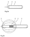
- Figure 1 shows as a preferred embodiment of the invention an arrangement 1 for electro-thermal treatment of the human or animal body, essentially from a catheter 2 with a core electrode 3 and one Jacket electrode 4 and a handling part 5 for The catheter 2 is guided, the catheter 2 being detailed is shown in Figures 2a and 2b.
- the catheter 2 enables adjustment of the axial distance between the two electrodes 3, 4 to the field distribution to be able to specify in the therapy area.
- the catheter 2 has the cylindrical core electrode 3 Stainless steel with a diameter of 800 microns on their Shell surface down to its distal end to the electrical Insulation with a 50 micron thick polyimide layer 6 is.
- This coated core electrode 3 is coaxial slidable in the hollow cylindrical jacket electrode 4, which is also made of stainless steel and has an inner diameter of 900 ⁇ m.
- the outer diameter of the jacket electrode 4 is 1500 ⁇ m with a length of 10 cm.
- the core electrode 3 After insertion of the catheter 2 into the tissue, then extend the core electrode 3 in the axial direction and thus forms with the insulating polyimide layer 6 and Sheath electrode 4 has a dipole configuration, as in Figure 2b is shown.
- the axial displacement allows the core electrode 3 also an adjustment of axial distance between the two electrodes 3, 4 and thus influencing the field distribution in the Therapy area.
- Operation of the slide mechanism for the core electrode 3 is carried out by a push button rocker 7, which for ergonomic reasons as a pistol grip molded handling part 5 is integrated.
- a switch 8 with which the Electrode arrangement connected to an HF generator can be with the handling part 5 via an electrical Lead 9 is connected.
- the Handling part 5 has an unlocking mechanism 10, through which the core electrode 3 is released and then can be pulled axially out of the jacket electrode 4. After unlocking a locking mechanism 11 can then the jacket electrode 4 are also pulled out axially.
- the separation of the electrodes 3, 4 from the handling part 5 enables a simple sterilization and subsequent Recycling electrodes 3, 4.
- the catheter consisting of core and jacket electrodes 3, 4 2 is via a rotatable receiving bearing 12 with the handling part 5 connected and enabled by its angled Form a work adapted to the field of vision of the doctor, like it is for example with the turbinate coagulation necessary is.
- the arrangement 1 shown enables the introduction a rinsing liquid into the tissue in the therapy area, to improve the electrical coupling.
- the handling part 5 therefore determines from the adjacent one Voltage and the current across the electrodes 3, 4 the tissue impedance and gives an appropriate amount of rinsing liquid to the tissue in order to keep the tissue impedance constant.
- the rinsing liquid is the handling part 5 a hose line 13 fed from a separate flushing pump and through the hollow jacket electrode 4 into the therapy area pumped. The rinsing liquid then passes through there Gap between core electrode 3 and jacket electrode 4 in the tissue out.
- FIGS. 3a and 3b each show a catheter 14 and 15, with a proximal electrode 17 or 19 and a distal Electrode 16 or 18, the distance between the two electrodes 16, 17 and 18, 19 is constant by one to achieve predetermined field distribution and a simple one To allow construction of the catheter 14, 15.
- the two Electrodes 16, 17 and 18, 19 are cylindrical and are also on their faces by a cylindrical connecting element 20 or 21 made of electrical insulating material mechanically connected to each other, the connecting element 20 or 21 as well the proximal electrode 17 or 19 for receiving the electrode lead has an axially extending hollow channel.
- the outer cross sections of the two electrodes 16, 17 and Cross section of the connecting element 20 is the same, so that the Outer contour of the catheter 14 also at the transition points between the electrodes 16, 17 and the connecting element 20 is smooth, thereby introducing the catheter 14 into the Body of the patient is relieved.
- the catheter 15 shown has the proximal electrode 19 in contrast, a larger cross-section than the distal Electrode 18 and the connecting element 21, the proximal electrode 19 at the transition point to the connecting element 21 conical on the cross section of the connecting element 21 tapered.
- Figure 4 also shows a catheter 22, which differs from the essentially described through catheters distinguishes the larger number of electrodes 23.1 to 23.5 itself, which is arranged along the longitudinal axis of the catheter 22 are and essentially of annular metallic Coatings exist on the outer surface of a cylindrical Carrier element 24 made of electrically insulating Material are applied.
- Contacting the electrodes 23.1 to 23.5 takes place individually through feed lines, that in an axially extending hollow channel of the carrier element are misplaced.
- the larger Number of electrodes 23.1 to 23.5 the partial current density on the electrodes 23.1 to 23.5, which leads to a large temperature rise is prevented.
- Second lets a different one due to the overlay of the individual fields Generate field distribution than with only two electrodes. There is also the possibility of field distribution targeted by switching individual electrode pairs on or off to influence.
- FIG. 5 shows another embodiment of the invention a catheter 25 which is flexible and thus an introduction also in body cavities with curved entrance channels, what especially with minimally invasive medicine (MIM) is important.
- the catheter 25 is essentially a cylindrical core electrode 26 made of spring steel wire, that of a hollow cylindrical jacket electrode 27 is surrounded, which is made of a flexible metal mesh is formed. Except for its distal end is the core electrode 26 on its outer surface with an electrically insulating Coating 28 provided around the two electrodes 26, 27 to isolate each other.
- FIGS. 6a, 6b and 6c show further advantageous embodiments of catheters 29, 30, 31 with one each hollow cylindrical proximal jacket electrode 32, 33, 34 and a cylindrical distal core electrode 36, 37, 38.
- the catheters 29, 30, 31 shown enable advantageously a supply of rinsing liquid into the tissue, the loss of fluid in the tissue during coagulation compensate and a related deterioration to prevent electrical coupling.
- the rinsing liquid is supplied by a axially extending hollow channel in the proximal jacket electrode 32, 33, 34 and is arranged by an extracorporeal Detergent pump guaranteed.
- the submission of the Flushing liquid in the therapy area takes place in the shown Catheters 29, 30, 31, however, in different Wise.
- the catheter 29 shown in FIG the lateral surface of the jacket electrode 32 several distally arranged Breakthroughs 35 through which the washing liquid can emerge from the hollow channel into the tissue.
- the rinsing liquid enters the catheter 30 shown in FIG. 6b however, through a gap between the jacket electrode 33 and core electrode 36 into the tissue.
- the in Figure 6c shown catheter 31 instead has one in the axial direction through hollow channel, which also passes through the core electrode 37 and in the distal End of the core electrode 37 opens, so that the Flushing fluid on the distal face of the distal Electrode 37 emerges in the tissue.
- Physiological saline is preferably used as the rinsing liquid used for good electrical coupling to the tissue and by limiting the temperature reduces the risk of tissue carbonization to ⁇ 100 ° C.
- the insulation of the two electrodes 32, 38 and 36, 33 and 34, 37 against each other also takes place here through, one applied to the core electrode 36, 37, 38 Coating 39, 40, 41 made of electrically insulating material.
- the hollow channel can be used instead of the flushing liquid of the catheter 31 shown in FIG. 6c also one Optical fiber for a modified optical biopsy, the via a measurement of the backscatter signal or the Tissue fluorescence when irradiated a precise positioning of the catheter 31 in the therapy area.
- laser transmission through an integrated Optical fiber depending on the used Wavelength also the possibility of measuring blood flow by Doppler measurement.
- the one such optical fiber transmitted into the therapy area Laser radiation also for thermo-optical tissue coagulation be used.
- FIG. 7 finally shows a further catheter 42 which an adjustment of the electrode spacing enables the To be able to influence field distribution in the therapy area.
- the catheter 42 shown has a cylindrical one Carrier element 43 made of electrically insulating material, at its distal end a distal electrode 44 laterally is applied as an annular metallic coating.
- This carrier element 43 is of a hollow cylindrical design proximal electrode 45, the outer diameter of the carrier element 43 is smaller than the inner diameter the proximal electrode 45 so that the support member 43 with the distal electrode 44 in axial Direction is shiftable to adjust the electrode spacing to be able to.
- the carrier element is at its distal end 43 ground as a spike to introduce of catheter 42 into the patient's body.
- the invention is not limited in its execution the preferred embodiments given above. Rather, a number of variants are conceivable, which fundamentally different from the solution shown makes use of any type.
Abstract
Description
Die Erfindung betrifft eine Anordnung zur elektrothermischen
Behandlung des menschlichen oder tierischen
Körpers, insbesondere zur Elektrokoagulation oder Elektrotomie,
gemäß dem Oberbegriff des Anspruchs 1.The invention relates to an arrangement for electrothermal
Treatment of human or animal
Body, especially for electrocoagulation or electrotomy,
according to the preamble of
Es ist seit längerem in der Chirurgie bekannt, zur Gewebekoagulation und zur Gewebetrennung hochfrequente Wechselströme im Frequenzbereich von 300 kHz bis 2 MHz zu verwenden, wodurch das behandelte Gewebe koaguliert bzw. vaporisiert wird, was als Elektrokoagulation bzw. Elektrotomie bezeichnet wird. Hierbei ist zu unterscheiden zwischen der monopolaren und der bipolaren HF-Thermotherapie.It has long been known in surgery for tissue coagulation and high-frequency alternating currents for tissue separation to be used in the frequency range from 300 kHz to 2 MHz, whereby the treated tissue coagulates or vaporises becomes what is called electrocoagulation or electrotomy referred to as. A distinction must be made between the monopolar and bipolar RF thermotherapy.
Bei der monopolaren HF-Thermotherapie wird eine Elektrode - auch als Neutralelektrode bezeichnet - als großflächige Patientenableitung ausgelegt und in der Nähe der Eingriffsstelle am Patienten angebracht. Die eigentliche Arbeitselektrode - auch als Aktivelektrode bezeichnet - ist in ihrer Form an die jeweilige Anwendung angepaßt. So werden zur Gewebekoagulation großflächige Kugel-, Platten- oder Nadelelektroden verwendet, während bei der Gewebetrennung dünne Lanzetten- oder Schlingenelektroden eingesetzt werden.With monopolar HF thermotherapy, an electrode - also referred to as a neutral electrode - as a large-area patient lead designed and close to the point of intervention attached to the patient. The actual working electrode - also called active electrode - is in their Form adapted to the respective application. So become Tissue coagulation of large spherical, plate or needle electrodes used while thin tissue separation Lancet or loop electrodes are used.
Bei der bipolaren HF-Thermotherapie hingegen sind beide Elektroden in unmittelbarer Nähe zur Eingriffsstelle angeordnet, so daß die Wirkung des Wechselstroms auf die unmittelbare Umgebung der Eingriffsstelle begrenzt ist, wodurch ein hohes Maß an Sicherheit für Patient und Anwender gegeben ist, da Unfälle durch kapazitive Leckströme oder Verbrennung an der Neutralelektrode nicht mehr auftreten können. Ein weiterer Vorteil der bipolaren HF-Thermotherapie besteht in dem wesentlich geringeren Lastwiderstand des Gewebes zwischen den beiden Elektroden, was unter Beibehaltung des thermischen Effekts eine Verringerung der erforderlichen Generatorleistung ermöglicht.With bipolar HF thermotherapy, however, both are Electrodes arranged in the immediate vicinity of the point of intervention, so that the effect of alternating current on the immediate Environment of the point of intervention is limited, whereby a high level of safety for patient and user is because of accidents caused by capacitive leakage currents or combustion can no longer occur at the neutral electrode. Another advantage of bipolar HF thermotherapy consists in the much lower load resistance of the fabric between the two electrodes, while maintaining a reduction in the thermal effect required Generator power enabled.
Die HF-Thermotherapie läßt sich weiterhin einteilen nach der Lage der Elektroden in die Oberflächenkoagulation einerseits und die Tiefenkoagulation andererseits.HF thermotherapy can still be divided into two the position of the electrodes in the surface coagulation on the one hand and deep coagulation on the other.
Bei der Oberflächenkoagulation werden in der bipolaren Technik zwei parallel angeordnete Tastelektroden verwendet, die auf die Gewebeoberfläche aufgesetzt werden, wodurch das darunterliegende Gewebe infolge des Stromflusses erhitzt und damit koaguliert wird.In the case of surface coagulation, bipolar Technology uses two parallel electrodes, which are placed on the surface of the fabric, making the underlying tissue is heated due to the flow of current and is coagulated with it.
Bei der Tiefenkoagulation ist es zur monopolaren Elektrotomie bekannt, Nadel-, Lanzetten- oder Schlingenelektroden zu verwenden. Hierbei müssen an der Aktivelektrode elektrische Lichtbögen generiert werden, um das vor der Aktivelektrode liegende Gewebe zu vaporisieren und damit einen Gewebsschnitt zu realisieren. Bei der monopolaren Technik ist dies verhältnismäßig einfach, da es hier nur einer bestimmten Feldstärke bedarf, um an der Aktivelektrode einen Funkenüberschlag auszulösen. Die bipolare Technik stellt hier größere Anforderungen an die Konzeption der Elektrodenkonfiguration, da die physikalischen Vorgänge hierbei nicht einfach zu beherrschen sind. Es sind deshalb nur wenige bipolare Elektrodenanordnungen für die Tiefenkoagulation bekannt, so beispielsweise die bipolare Nadelelektrode, die sich unter anderem zur Myomtherapie eignet. Diese vorbekannte bipolare Elektrodenanordnung besteht aus zwei parallel angeordneten Nadelelektroden, die in das Gewebe eingestochen werden, wodurch das zwischen den Elektroden liegende Gewebe infolge des Stromflusses erhitzt und damit koaguliert wird.With deep coagulation, it is a monopolar electrotomy known to needle, lancet or loop electrodes use. Electrical must be on the active electrode Arcs are generated around the front of the active electrode vaporize lying tissue and thus a tissue section to realize. When it comes to monopolar technology this is relatively easy since there is only one particular here Field strength needs to spark at the active electrode trigger. The bipolar technique here greater demands on the design of the electrode configuration, because the physical processes are not are easy to master. There are therefore only a few bipolar ones Electrode arrangements known for deep coagulation, for example the bipolar needle electrode is suitable for myoma therapy, among other things. This previously known Bipolar electrode arrangement consists of two in parallel arranged needle electrodes that are inserted into the tissue , which means that between the electrodes Tissue is heated as a result of the current flow and thus coagulates becomes.
Nachteilig bei den bekannten bipolaren Elektrodenanordnungen zur Tiefenkoagulation ist jedoch die relativ aufwendige Plazierung der Elektroden durch zwei Einstichstellen. Darüber hinaus läßt sich die Feldverteilung vom Anwender nur relativ ungenau vorherbestimmen, da die relative Lage der beiden Elektroden zueinander in der Regel nicht exakt vorgegeben werden kann.A disadvantage of the known bipolar electrode arrangements for deep coagulation, however, is the relatively complex one Placement of the electrodes by two puncture points. About that In addition, the field distribution can only be done by the user predict relatively imprecisely because the relative location of the As a rule, the two electrodes are not exactly specified to one another can be.
Es ist aus DE 43 22 955 A1 weiterhin bekannt, zur Koagulation
von Körpergewebe Laserstrahlung zu verwenden, die über
einen zylindrischen Lichtwellenleiter ins Therapiegebiet
übertragen werden kann, wobei der vorbekannte Lichtwellenleiter
zusätzlich auch die Übertragung von Ultraschallenergie
ermöglicht, so daß die beiden Therapieverfahren der Ultraschall-Gewebetrennung
und der Laser-Koagulation kombiniert
werden können.It is also known from
Aus DE 44 32 666 A1 ist weiterhin ein Wellenleiter bekannt,
der neben der Übertragung von Ultraschallwellen und Laserstrahlung
auch die Übertragung von Hochfrequenzenergie ermöglicht,
um gleichzeitig zur Laser- und Ultraschallchirurgie
auch die eingangs erwähnten Verfahren der Hochfrequenzchirurgie
anwenden zu können. Hierzu ist der vorbekannte
Wellenleiter zylindrisch ausgeführt und weist zur Übertragung
der Hochfrequenzenergie zwei ebenfalls zylindrische
Schichten aus elektrisch leitfähigem Material auf, die
elektrisch gegeneinander isoliert sind. Der vorbekannte
Wellenleiter ermöglicht somit zwar die Übertragung von
Hochfrequenzenergie von einem extrakorporal angeordneten
Hochfrequenzgenerator ins Therapiegebiet, gestattet jedoch
keine Abgabe der Hochfrequenzenergie an das Körpergewebe.A waveguide is also known from
Der Erfindung liegt somit die Aufgabe zugrunde, eine Anordnung zur elektro-thermischen Behandlung des menschlichen oder tierischen Körpers zu schaffen, die mittels einer bipolaren Elektrodenanordnung eine interstitielle Gewebekoagulation ermöglicht und die vorstehend genannten Nachteile der bekannten Anordnungen dieser Art vermeidet.The invention is therefore based on the object of an arrangement for the electro-thermal treatment of human beings or to create animal bodies by means of a bipolar Electrode arrangement for interstitial tissue coagulation enables and the disadvantages mentioned above avoids the known arrangements of this type.
Die Aufgabe wird, ausgehend von einer Anordnung gemäß dem
Oberbegriff des Anspruchs 1, durch die im kennzeichnenden
Teil des Anspruchs 1 angegebenen Merkmale gelöst.The task is based on an arrangement according to the
Preamble of
Die Erfindung schließt die technische Lehre ein, zur Thermotherapie eine bipolare Elektrodenanordnung zu verwenden, bei der die beiden Elektroden hintereinander auf einem langgestreckten Katheter angeordnet sind, um eine gemeinsame Einführung der beiden Elektroden in den Körper durch eine einzige Einstichstelle zu ermöglichen, wobei die beiden Elektroden mit dem Katheter verbunden oder ein Bestandteil des Katheters sind.The invention includes the technical teaching of thermotherapy to use a bipolar electrode arrangement where the two electrodes are in a row on one elongated catheters are arranged to form a common Introduction of the two electrodes into the body through one to allow only puncture site, the two Electrodes connected to the catheter or a component of the catheter.
Der Begriff Katheter ist hierbei und im folgenden allgemein zu verstehen und nicht auf die vorzugsweise verwendeten und im folgenden ausführlich beschriebenen hohlzylindrischen Anordnungen beschränkt, sondern auch mit massiven Anordnungen nahezu beliebiger Querschnitte realisierbar. Maßgebend für die erfindungsgemäße Funktion ist lediglich, daß die beiden Elektroden gemeinsam durch eine Einstichstelle in den Körper des Patienten eingeführt werden können.The term catheter is general here and below to understand and not on the preferably used and hollow cylindrical described in detail below Arrangements limited, but also with massive arrangements almost any cross-section can be realized. Relevant for the function according to the invention is only that both electrodes together through a puncture site in the patient's body can be inserted.
Durch den erfindungsgemäßen Katheter ist es nunmehr erstmals möglich, die Elektroden in tiefen Gewebsschichten zu plazieren und dort eine partielle Gewebekoagulation zu erreichen.It is now the first time thanks to the catheter according to the invention possible to close the electrodes in deep tissue layers place and there to achieve partial tissue coagulation.
Die Elektroden sind bei der erfindungsgemäßen Anordnung für die Zuführung der zur Gewebeerwärmung erforderlichen elektrischen Energie mit einer Stromquelle verbunden, wobei der Begriff Stromquelle nicht auf Stromquellen im engeren Sinne mit einem konstanten Strom beschränkt ist, sondern auch die vorzugsweise verwendeten Wechselstromgeneratoren, insbesondere Hochfrequenzgeneratoren, einschließt.In the arrangement according to the invention, the electrodes are for the supply of the electrical necessary for tissue heating Energy connected to a power source, the The term power source does not refer to power sources in the narrower sense is limited with a constant current, but also the preferably used alternators, in particular High frequency generators.
In einer vorteilhaften Variante der Erfindung ist der axiale Abstand zwischen den beiden Elektroden einstellbar, um die Feldverteilung variieren zu können. Beträgt die Isolatorlänge zwischen den beiden Elektroden in axialer Richtung beispielsweise weniger als das zweifache des Elektrodendurchmessers, so lassen sich vorteilhaft kugelförmige Koagulationsnekrosen erzielen, wohingegen die Form der Koagulationsnekrosen bei größeren Isolatorlängen eher oval ist.In an advantageous variant of the invention, the axial Distance between the two electrodes adjustable to to be able to vary the field distribution. Is the insulator length between the two electrodes in the axial direction for example less than twice the electrode diameter, this advantageously enables spherical coagulation necrosis achieve, whereas the shape of the coagulation necrosis is oval for longer insulator lengths.
In der bevorzugten Ausführungsform dieser Variante ist deshalb
vorgesehen, die proximale Elektrode mindestens an ihrem
distal gelegenen Ende hohl auszuführen, um die distale
Elektrode in ihrem Inneren aufnehmen zu können. Um hierbei
eine axiale Verschiebbarkeit der distalen Elektrode in der
proximalen Elektrode zu ermöglichen ist der Außenquerschnitt
der distalen Elektrode kleiner als der Innenquerschnitt
der proximalen Elektrode. Hierbei ist es wichtig,
die beiden Elektroden in geeigneter Weise elektrisch gegeneinander
zu isolieren, da die beiden Elektroden in axialer
Richtung überlappen können. Hierzu ist auf der Innenseite
der proximalen Elektrode oder auf der Außenseite der distalen
Elektrode eine elektrische Isolation vorgesehen, die
beispielsweise - wie in der eingangs angeführten Druckschritt
DE 44 32 666 A1 - aus einer dielektrischen Beschichtung
oder einer Isolierstoffhülse bestehen kann, die
vorzugsweise aus PTFE oder Polyimid besteht, wobei der
Querschnitt der Isolierstoffhülse vorzugsweise derart an
den Querschnitt der distalen bzw. proximalen Elektrode angepaßt
ist, daß die Isolierstoffhülse mit der proximalen
bzw. distalen Elektrode eine Preßpassung bildet und somit
auf der Elektrode fixiert ist. Die beiden Elektroden sind
also koaxial angeordnet und in axialer Richtung gegeneinander
verschiebbar, um die Feldverteilung ändern zu können,
wobei die distale Elektrode auf einem Teil ihrer Längserstreckung
von der proximalen Elektrode aufgenommen wird.In the preferred embodiment of this variant is therefore
provided the proximal electrode at least on her
distal end to run hollow to the distal
To be able to record the electrode inside. To do this
an axial displacement of the distal electrode in the
The outer cross section is to enable the proximal electrode
of the distal electrode is smaller than the inner cross section
the proximal electrode. It is important here
the two electrodes in a suitable manner electrically against each other
to isolate because the two electrodes are in axial
Direction can overlap. This is on the inside
the proximal electrode or on the outside of the distal
Electrical insulation provided the electrode
for example - as in the printing step mentioned at the
Der Querschnitt der beiden Elektroden ist in dieser Variante der Erfindung wie auch den anderen Erfindungsvarianten vorzugsweise zylindrisch, wobei der Innendurchmesser der proximalen Elektrode in dieser Variante größer sein muß als der Außendurchmesser der distalen Elektrode, damit die distale Elektrode in axialer Richtung verschiebbar ist. Die Erfindung ist jedoch nicht auf zylindrische Elektrodenformen beschränkt, sondern auch mit anderen Elektrodenquerschnitten realisierbar. Maßgebend für die erfindungsgemäße Funktion ist in dieser Variante der Erfindung lediglich, daß der Innenquerschnitt der proximalen Elektrode derart an den Außenquerschnitt der proximalen Elektrode angepaßt ist, daß die distale Elektrode in der proximalen Elektrode in axialer Richtung verschoben werden kann, um den axialen Abstand zwischen den beiden Elektroden verändern zu können.The cross section of the two electrodes is in this variant the invention as well as the other variants of the invention preferably cylindrical, the inner diameter of the proximal electrode in this variant must be larger than the outer diameter of the distal electrode, hence the distal Electrode is displaceable in the axial direction. The However, the invention is not based on cylindrical electrode shapes limited, but also with other electrode cross-sections realizable. Decisive for the invention In this variant of the invention, the function is merely that the inner cross section of the proximal electrode is such the outer cross section of the proximal electrode is adapted, that the distal electrode in the proximal electrode in axial direction can be shifted by the axial distance to be able to change between the two electrodes.
In einer anderen Variante der Erfindung wird die Einstellung des axialen Abstandes zwischen den beiden Elektroden durch ein langgestrecktes Trägerelement aus elektrisch isolierendem Material ermöglicht, das in der proximalen Elektrode verschiebbar angeordnet ist und an seinem distalen Bereich seitlich die distale Elektrode aufweist. Die proximale Elektrode ist deshalb zumindest an ihrem distalen Ende hohl ausgeführt, um das Trägerelement aufnehmen zu können. Der Innenquerschnitt der proximalen Elektrode ist hierbei derart an den Außenquerschnitt des Trägerelements angepaßt, daß das Trägerelement in axialer Richtung verschiebbar ist, um den axialen Abstand zwischen dem distalen Ende der proximalen Elektrode und der auf der Trägerelement angeordneten distalen Elektrode einstellen zu können. Die distale Elektrode ist in dieser Variante der Erfindung seitlich an dem elektrisch isolierenden Trägerelement angebracht und kann beispielsweise aus einer ringförmigen metallischen Beschichtung oder einer metallischen Hülse bestehen, die zur Montage axial auf das Trägerelement aufgeschoben wird und mit diesem eine Preßpassung bildet.In another variant of the invention, the setting the axial distance between the two electrodes through an elongated support element made of electrically insulating Material allows that in the proximal electrode is slidably disposed and at its distal Area has the distal electrode laterally. The proximal The electrode is therefore at least at its distal end hollow to accommodate the support member. The inner cross section of the proximal electrode is here adapted to the outer cross section of the carrier element in such a way that the carrier element is displaceable in the axial direction, by the axial distance between the distal end of the proximal electrode and that arranged on the carrier element to be able to adjust the distal electrode. The distal In this variant of the invention, the electrode is on the side attached to the electrically insulating support member and can, for example, from an annular metallic coating or consist of a metallic sleeve that for Assembly is pushed axially onto the carrier element and forms an interference fit with this.
Gemäß einer anderen Variante der Erfindung ist der Abstand der beiden Elektroden dagegen vorgegeben, um einen einfachen Aufbau des Katheters zu erreichen und eine vorgegebene Feldverteilung sicherzustellen. Der Katheter weist hierzu ebenfalls ein langgestrecktes Trägerelement aus elektrisch isolierendem Material auf, an dessen Seite die Elektroden in axialer Richtung fixiert und zueinander beabstandet angeordnet sind. Das Trägerelement dient hierbei zum einen zur mechanischen Fixierung der Elektroden, um aufgrund des konstanten Elektrodenabstandes eine vorgegebene Feldverteilung zu erreichen. Zum anderen hat das Trägerelement die Aufgabe, die beiden Elektroden elektrisch gegeneinander zu isolieren und besteht deshalb aus elektrisch isolierendem Material. In der bevorzugten Ausführungsform dieser Variante weist das Trägerelement einen zylindrischen Querschnitt auf, wobei die beiden Elektroden hohlzylindrisch ausgeführt und bezüglich der Längsachse des Trägerelements umlaufend angeordnet sind. Die Elektroden können hierzu beispielsweise als metallische Beschichtung auf die Oberfläche des Trä-gerelements aufgebracht werden oder jeweils aus einer metallischen Hülse bestehen, die auf das Trägerelement aufgeschoben wird und mit diesem eine Preßpassung bildet.According to another variant of the invention, the distance is the two electrodes, on the other hand, are given a simple one Structure of the catheter to achieve and a predetermined Ensure field distribution. The catheter points to this also an elongated support element made of electrical insulating material on the side of which the electrodes fixed in the axial direction and spaced apart are. The carrier element serves on the one hand for the mechanical fixation of the electrodes, due to the constant electrode spacing a predetermined field distribution to reach. On the other hand, the carrier element has the Task, the two electrodes electrically against each other isolate and therefore consists of electrically insulating Material. In the preferred embodiment of this variant the carrier element has a cylindrical cross section on, the two electrodes being hollow cylindrical and revolving with respect to the longitudinal axis of the carrier element are arranged. For this purpose, the electrodes can, for example as a metallic coating on the surface of the carrier element be applied or each made of a metallic Sleeve exist, which are pushed onto the carrier element and forms an interference fit with it.
In einer anderen Ausführungsform dieser Variante wird die axiale Fixierung der Elektroden nicht durch deren Anordnung auf einem Trägerelement bewirkt, sondern durch jeweils ein Verbindungselement zwischen den Elektroden, welches die Elektroden an ihren Stirnseiten miteinander verbindet. Neben der axialen Fixierung der Elektroden hat das Verbindungselement auch die Aufgabe, die beiden Elektroden gegeneinander zu isolieren und besteht deshalb aus einem elektrisch isolierenden Material. Die Elektroden und die Verbindungsstücke sind hierbei vorzugsweise zylindrisch und weisen denselben Querschnitt auf, so daß die Außenkontur des Katheters an den Übergangsstellen zwischen den Elektroden und den Verbindungselementen einen stetigen Verlauf ohne hervorspringende Kanten aufweist, was bei der Einführung des Katheters in den Körper des Patienten wichtig ist, um unnötige Verletzungen zu vermeiden.In another embodiment of this variant, the axial fixation of the electrodes not by their arrangement effected on a carrier element, but by one Connection element between the electrodes, which the Connects electrodes on their end faces. Next the connecting element has the axial fixation of the electrodes also the task of putting the two electrodes against each other to isolate and therefore consists of an electrical insulating material. The electrodes and the connectors are preferably cylindrical and have the same cross-section, so that the outer contour of the catheter at the transition points between the electrodes and the connecting elements a continuous course without protruding edges, which when introducing of the catheter in the patient's body is important to to avoid unnecessary injuries.
Gemäß einer weiterbildenden Variante der Erfindung sind mehr als zwei Elektroden vorgesehen, die in axialer Richtung des Katheters zueinander beabstandet angeordnet sind. Die Elektroden können beispielsweise - wie bereits vorstehend beschrieben - seitlich an einem langgestreckten Trägerelement angebracht sein oder - wie bereits zuvor erläutert - jeweils durch ein Verbindungselement aus elektrisch isolierendem Material voneinander getrennt werden.According to a further variant of the invention more than two electrodes are provided in the axial direction of the catheter are spaced apart. The electrodes can, for example - as already above described - on the side of an elongated support element be attached or - as already explained above - each by a connecting element made of electrical insulating material.
In der bevorzugten Ausführungsform dieser Variante können die einzelnen, entlang der Längsachse des Katheters axial verteilt angeordneten Elektrodenpaare getrennt angesteuert werden und weisen hierzu jeweils getrennte Zuleitungen auf, die vorzugsweise durch einen Hohlkanal im Inneren des Katheters aus dem Körper herausgeführt sind und mit einem entsprechenden Steuergerät verbunden werden können, welches eine individuelle Einstellung beispielsweise von Strom, Spannung und/oder Frequenz ermöglicht. Aufgrund der Überlagerung der von den einzelnen Elektrodenpaaren erzeugten Felder ist es auf diese Weise möglich, die Feldverteilung in weiten Grenzen frei vorzugeben, um beispielsweise bei einer Elektrokoagulation möglichst wenig gesundes Gewebe zu zerstören. In einer vorteilhaften Weiterbildung dieser Variante weist das extrakorporale Steuergerät mehrere Speicherelemente auf, in denen die elektrischen Parameter wie Strom, Spannung und Frequenz für verschiedene Feldverteilungen gespeichert sind, so daß der Benutzer sich lediglich für die gewünschte Feldverteilung entscheiden muß, woraufhin das Steuergerät dann die zur Erreichung dieser Feldverteilung erforderlichen elektrischen Parameter aus dem jeweiligen Speicherelement ausliest und die einzelnen Elektrodenpaare entsprechend ansteuert.In the preferred embodiment of this variant can the individual, axially along the longitudinal axis of the catheter Distributed pairs of electrodes controlled separately and have separate supply lines for this, preferably through a hollow channel inside the catheter are led out of the body and with one corresponding control unit can be connected, which an individual setting of electricity, for example, Voltage and / or frequency enables. Because of the overlay that generated by the individual pairs of electrodes Fields it is possible in this way, the field distribution free to specify within wide limits, for example at electrocoagulation as little healthy tissue as possible to destroy. In an advantageous development of this variant the extracorporeal control device has several storage elements on where the electrical parameters like Current, voltage and frequency for different field distributions are stored so that the user is only must decide for the desired field distribution, whereupon the control unit then to achieve this field distribution required electrical parameters from the respective Reads memory element and the individual electrode pairs controls accordingly.
Andere vorteilhafte Weiterbildungen der Erfindung sind in den Unteransprüchen gekennzeichnet bzw. werden nachstehend zusammen mit der Beschreibung der bevorzugten Ausführung der Erfindung anhand der Figuren näher dargestellt. Es zeigen:
Figur 1- als bevorzugtes Ausführungsbeispiel der Erfindung eine Anordnung zur elektrothermischen Behandlung mit einem Katheter zur Einführung der Elektroden in den Körper und einem Handhabungsteil zur Führung des Katheters,
- Figur 2a, 2b
- den Katheter der Anordnung aus
Figur 1 mit eingefahrener bzw. ausgefahrener Kernelektrode, - Figur 3a, 3b
- verschiedene Katheter mit feststehenden Elektroden zur Erreichung einer vorgegebenen Feldverteilung,
Figur 4- einen Katheter mit fünf Elektroden zur Ermöglichung besonderer Feldverteilungsformen,
Figur 5- einen flexiblen Katheter zum Einsatz in der minimalinvasiven Chirurgie,
- Figur 6a, 6b, 6c
- verschiedene Katheter, die eine Zuführung von Spülflüssigkeit ermöglichen sowie
Figur 7- einen weiteren Katheter mit einstellbarem Elektrodenabstand.
- Figure 1
- as a preferred embodiment of the invention, an arrangement for electrothermal treatment with a catheter for introducing the electrodes into the body and a handling part for guiding the catheter,
- Figure 2a, 2b
- 1 with the core electrode retracted or extended,
- Figure 3a, 3b
- various catheters with fixed electrodes to achieve a given field distribution,
- Figure 4
- a catheter with five electrodes to enable special forms of field distribution,
- Figure 5
- a flexible catheter for use in minimally invasive surgery,
- Figure 6a, 6b, 6c
- various catheters that allow the supply of irrigation fluid as well
- Figure 7
- another catheter with adjustable electrode spacing.
Figur 1 zeigt als bevorzugtes Ausführungsbeispiel der Erfindung
eine Anordnung 1 zur elektro-thermischen Behandlung
des menschlichen oder tierischen Körpers, die im wesentlichen
aus einem Katheter 2 mit einer Kernelektrode 3 und einer
Mantelelektrode 4 sowie einem Handhabungsteil 5 zur
Führung des Katheters 2 besteht, wobei der Katheter 2 detailliert
in den Figuren 2a und 2b dargestellt ist.Figure 1 shows as a preferred embodiment of the invention
an
Der Katheter 2 ermöglicht eine Einstellung des axialen Abstandes
zwischen den beiden Elektroden 3, 4, um die Feldverteilung
im Therapiegebiet vorgeben zu können. Hierzu
weist der Katheter 2 die zylindrische Kernelektrode 3 aus
Edelstahl mit einem Durchmesser von 800 µm auf, die an ihrer
Mantelfläche bis auf ihr distales Ende zur elektrischen
Isolierung mit einer 50 µm dicken Polyimidschicht 6 versehen
ist. Diese beschichtete Kernelektrode 3 liegt koaxial
verschiebbar in der hohlzylindrischen Mantelelektrode 4,
die ebenfalls aus Edelstahl besteht und einen Innendurchmesser
von 900 µm aufweist. Der Außendurchmesser der Mantelelektrode
4 beträgt 1500 µm bei einer Länge von 10 cm.The
Durch einen in das Handhabungsteil 5 integrierten Verschiebemechanismus
läßt sich die innere Kernelektrode 3 vor dem
Einstechen des Katheters 2 in das Gewebe zurückziehen, so
daß die Kernelektrode 3 und die Mantelelektrode 4 zusammen
einen symmetrisch angeschliffenen Einstichdorn bilden, wie
in Figur 2a dargestellt ist.By a sliding mechanism integrated in the
Nach dem Einführen des Katheters 2 in das Gewebe läßt sich
die Kernelektrode 3 dann in axialer Richtung ausfahren und
bildet so mit der isolierenden Polyimidschicht 6 und der
Mantelelektrode 4 eine Dipolkonfiguration, wie in Figur 2b
dargestellt ist. Darüber hinaus ermöglicht die axiale Verschiebung
der Kernelektrode 3 auch eine Einstellung des
axialen Abstandes zwischen den beiden Elektroden 3, 4 und
damit eine gezielte Beeinflussung der Feldverteilung im
Therapiegebiet. Die Bedienung des Verschiebemechanismus für
die Kernelektrode 3 erfolgt durch eine Druckknopfwippe 7,
die in das aus ergonomischen Gründen als Pistolenhandgriff
geformte Handhabungsteil 5 integriert ist. Darüber hinaus
enthält das Handhabungsteil 5 einen Schalter 8, mit dem die
Elektrodenanordnung an einen HF-Generator angeschlossen
werden kann, der mit dem Handhabungsteil 5 über eine elektrische
Zuleitung 9 verbunden ist. Weiterhin weist das
Handhabungsteil 5 einen Entriegelungsmechanismus 10 auf,
über den die Kernelektrode 3 freigegeben und anschließend
axial aus der Mantelelektrode 4 herausgezogen werden kann.
Nach dem Entriegeln eines Verschlußmechanismus 11 kann
dann auch die Mantelelektrode 4 axial herausgezogen werden.
Die Trennung der Elektroden 3, 4 von dem Handhabungsteil 5
ermöglicht in einfacher Weise eine Sterilisierung und anschließende
Wiederverwertung der Elektroden 3, 4.After insertion of the
Der aus Kern- und Mantelelektrode 3, 4 bestehende Katheter
2 ist über ein drehbares Aufnahmelager 12 mit dem Handhabungsteil
5 verbunden und ermöglicht durch seine abgewinkelte
Form ein an das Sichtfeld des Arztes angepaßtes Arbeiten,
wie es zum Beispiel bei der Nasenmuschelkoagulation
notwendig ist.The catheter consisting of core and
Weiterhin ermöglicht die dargestellte Anordnung 1 die Einleitung
einer Spülflüssigkeit in das Gewebe im Therapiegebiet,
um die elektrische Ankopplung zu verbessern. Hierdurch
läßt sich der während der Koagulation auftretende
Flüssigkeitsverlust ausgleichen, der sonst zu einer Änderung
der elektrischen Impedanz des Gewebes im Therapiegebiet
führt und die elektrische Ankopplung verschlechtert.
Das Handhabungsteil 5 ermittelt deshalb aus der anliegenden
Spannung und dem Strom über die Elektroden 3, 4 die Gewebeimpedanz
und gibt eine entsprechende Menge Spülflüssigkeit
an das Gewebe ab, um die Gewebeimpedanz konstant zuhalten.
Die Spülflüssigkeit wird dem Handhabungsteil 5 über
eine Schlauchleitung 13 von einer separaten Spülpumpe zugeführt
und durch die hohle Mantelelektrode 4 ins Therapiegebiet
gepumpt. Dort tritt die Spülflüssigkeit dann durch einen
Spalt zwischen Kernelektrode 3 und Mantelelektrode 4 in
das Gewebe aus.Furthermore, the
Die Figuren 3a und 3b zeigen jeweils einen Katheter 14 bzw.
15, mit einer proximalen Elektrode 17 bzw. 19 und einer distalen
Elektrode 16 bzw. 18, wobei der Abstand zwischen den
beiden Elektroden 16, 17 bzw. 18, 19 konstant ist, um eine
vorgegebene Feldverteilung zu erreichen und einen einfachen
Aufbau des Katheters 14, 15 zu ermöglichen. Die beiden
Elektroden 16, 17 bzw. 18, 19 sind hierbei zylindrisch ausgeführt
und werden an ihren Stirnflächen durch ein ebenfalls
zylindrisches Verbindungselement 20 bzw. 21 aus elektrisch
isolierendem Material mechanisch mit einander verbunden,
wobei das Verbindungselement 20 bzw. 21 wie auch
die proximale Elektrode 17 bzw. 19 zur Aufnahme der Elektrodenzuleitung
einen axial verlaufenden Hohlkanal aufweist.
Bei dem in Figur 3a dargestellten Katheter 14 sind
die Außenquerschnitte der beiden Elektroden 16, 17 und der
Querschnitt des Verbindungselements 20 gleich, so daß die
Außenkontur des Katheters 14 auch an den Übergangsstellen
zwischen den Elektroden 16, 17 und dem Verbindungselement
20 glatt ist, wodurch das Einführen des Katheters 14 in den
Körper des Patienten erleichtert wird. Bei dem in Figur 3b
dargestellten Katheter 15 weist die proximale Elektrode 19
dagegen einen größeren Querschnitt auf als die distale
Elektrode 18 und das Verbindungselement 21, wobei sich die
proximale Elektrode 19 an der Übergangsstelle zu dem Verbindungselement
21 konisch auf den Querschnitt des Verbindungselements
21 verjüngt.FIGS. 3a and 3b each show a
Figur 4 zeigt weiterhin einen Katheter 22, der sich von den
vorstehend beschriebenen Kathetern im wesentlichen durch
die größere Zahl von Elektroden 23.1 bis 23.5 unterscheidet
sich, die entlang der Längsachse des Katheters 22 angeordnet
sind und im wesentlichen aus ringförmigen metallischen
Beschichtungen bestehen, die auf die Mantelfläche eines zylindrischen
Trägerelements 24 aus elektrisch isolierendem
Material aufgebracht sind. Die Kontaktierung der Elektroden
23.1 bis 23.5 erfolgt jeweils einzeln durch Zuleitungen,
die in einem axial verlaufenden Hohlkanal des Trägerelements
verlegt sind. Zum einen läßt sich durch die größere
Zahl von Elektroden 23.1 bis 23.5 die partielle Stromdichte
an den Elektroden 23.1 bis 23.5 reduzieren, wodurch ein zu
großer Temperaturanstieg verhindert wird. Zum anderen läßt
sich durch die Überlagerung der einzelnen Felder eine andere
Feldverteilung erzeugen als bei nur zwei Elektroden.
Darüber hinaus besteht die Möglichkeit, die Feldverteilung
durch An- oder Abschaltung einzelner Elektrodenpaare gezielt
zu beeinflussen.Figure 4 also shows a
Figur 5 zeigt als weiteres Ausführungsbeispiel der Erfindung
einen Katheter 25, de flexibel ist und somit eine Einführung
auch in Körperhöhlen mit gekrümmten Eingangskanälen,
was insbesondere bei der minimalinvasiven Medizin
(MIM) wichtig ist. Der Katheter 25 besteht im wesentlichen
aus einer zylindrischen Kernelektrode 26 aus Federstahldraht,
die von einer hohlzylindrischen Mantelelektrode
27 umgeben ist, welche aus einem flexiblen Metallgeflecht
gebildet wird. Bis auf sein distales Ende ist die Kernelektrode
26 an seiner Mantelfläche mit einer elektrisch isolierenden
Beschichtung 28 versehen, um die beiden Elektroden
26, 27 gegeneinander zu isolieren.Figure 5 shows another embodiment of the invention
a
Die Figuren 6a, 6b und 6c zeigen weitere vorteilhafte Ausführungsformen
von Kathetern 29, 30, 31 mit jeweils einer
hohlzylindrischen proximalen Mantelelektrode 32, 33, 34 und
einer zylindrisch ausgeführten distalen Kernelektrode 36,
37, 38. Die dargestellten Katheter 29, 30, 31 ermöglichen
vorteilhaft eine Zuführung von Spülflüssigkeit in das Gewebe,
um den Flüssigkeitsverlust des Gewebes während der Koagulation
auszugleichen und eine damit verbundene Verschlechterung
der elektrischen Ankopplung zu verhindern.
Die Zuführung der Spülflüssigkeit erfolgt hierbei durch einen
axial verlaufenden Hohlkanal in der proximalen Mantelelektrode
32, 33, 34 und wird durch eine extrakorporal angeordnete
Spülmittelpumpe gewährleistet. Die Abgabe der
Spülflüssigkeit im Therapiegebiet erfolgt bei den dargestellten
Kathetern 29, 30, 31 dagegen in unterschiedlicher
Weise. So weist der in Figur 6a dargestellte Katheter 29 in
der Mantelfläche der Mantelelektrode 32 mehrere distal angeordnete
Durchbrüche 35 auf, durch welche die Spülflüssigkeit
aus dem Hohlkanal in das Gewebe austreten kann. Bei
dem in Figur 6b dargestellten Katheter 30 tritt die Spülflüssigkeit
dagegen durch einen Spalt zwischen Mantelelektrode
33 und Kernelektrode 36 in das Gewebe aus. Der in
Figur 6c dargestellte Katheter 31 weist statt dessen einen
in axialer Richtung durchgehenden Hohlkanal auf, der auch
durch die Kernelektrode 37 hindurchläuft und in der distalen
Stirnseite der Kernelektrode 37 mündet, so daß die
Spülflüssigkeit an der distalen Stirnfläche der distalen
Elektrode 37 in das Gewebe austritt. FIGS. 6a, 6b and 6c show further advantageous embodiments
of
Als Spülflüssigkeit wird vorzugsweise physiologische Kochsalzlösung
verwendet, die für eine gute elektrische Ankopplung
an das Gewebe sorgt und durch eine Begrenzung der Temperatur
auf <100°C die Gefahr der Gewebekarbonisation vermindert.
Die Isolation der beiden Elektroden 32, 38 bzw.
36, 33 bzw. 34, 37 gegeneinander erfolgt hierbei ebenfalls
durch, eine auf die Kernelektrode 36, 37, 38 aufgebrachte
Beschichtung 39, 40, 41 aus elektrisch isolierendem Material.Physiological saline is preferably used as the rinsing liquid
used for good electrical coupling
to the tissue and by limiting the temperature
reduces the risk of tissue carbonization to <100 ° C.
The insulation of the two
Anstelle der Zuführung von Spülflüssigkeit kann der Hohlkanal
des in Figur 6c dargestellten Katheters 31 auch einen
Lichtwellenleiter für eine modifizierte Optical Biopsy aufnehmen,
der über eine Messung des Rückstreusignals oder der
Gewebefluoreszenz bei Bestrahlung eine präzise Positionierung
des Katheters 31 im Therapiegebiet ermöglicht. Darüber
hinaus bietet eine Laserübertragung durch einen integrierten
Lichtwellenleiter in Abhängigkeit von der verwendeten
Wellenlänge auch die Möglichkeit einer Messung des Blutflusses
durch Dopplermessung. Weiterhin kann die über einen
derartigen Lichtwellenleiter ins Therapiegebiet übertragene
Laserstrahlung auch zur thermo-optischen Gewebekoagulation
verwendet werden. Schließlich besteht auch die Möglichkeit,
durch den Hohlkanal einen Temperatursensor zur Koagulationssteuerung
zu plazieren.The hollow channel can be used instead of the flushing liquid
of the
Figur 7 zeigt schließlich einen weiteren Katheter 42, der
eine Einstellung des Elektrodenabstands ermöglicht, um die
Feldverteilung im Therapiegebiet beeinflussen zu können.
Hierzu weist der dargestellte Katheter 42 ein zylindrisches
Trägerelement 43 aus elektrisch isolierendem Material auf,
an dessem distalen Ende eine distale Elektrode 44 seitlich
als ringförmige metallische Beschichtung aufgebracht ist. FIG. 7 finally shows a
Dieses Trägerelement 43 wird von einer hohlzylindrisch ausgeführten
proximalen Elektrode 45 geführt, wobei der Außendurchmesser
des Trägerelements 43 kleiner ist als der Innendurchmesser
der proximalen Elektrode 45, so daß das Trägerelement
43 mit der distalen Elektrode 44 in axialer
Richtung verschiebbar ist, um den Elektrodenabstand einstellen
zu können. An seinem distalen Ende ist das Trägerelement
43 als Einstichdorn angeschliffen, um die Einführung
des Katheters 42 in den Körper des Patienten zu erleichtern.This
Die Erfindung beschränkt sich in ihrer Ausführung nicht auf die vorstehend angegebenen bevorzugten Ausführungsbeispiele. Vielmehr ist eine Anzahl von Varianten denkbar, welche von der dargestellten Lösung auch bei grundsätzlich anders gearteten Ausführungen Gebrauch macht.The invention is not limited in its execution the preferred embodiments given above. Rather, a number of variants are conceivable, which fundamentally different from the solution shown makes use of any type.
Anordnung (1) zur elektro-thermischen Behandlung des
menschlichen oder tierischen Körpers, insbesondere zur Gewebekoagulation
oder Elektrotomie,
dadurch gekennzeichnet,
characterized,
Claims (9)
dadurch gekennzeichnet,
characterized,
dadurch gekennzeichnet,
characterized,
Applications Claiming Priority (3)
| Application Number | Priority Date | Filing Date | Title |
|---|---|---|---|
| DE19541566 | 1995-11-08 | ||
| DE19541566A DE19541566A1 (en) | 1995-11-08 | 1995-11-08 | Application system for HF surgery for interstitial thermotherapy in bipolar technology (HF-ITT) |
| EP96945879A EP0866672B1 (en) | 1995-11-08 | 1996-11-07 | Arrangement for electrothermal treatment of the human or animal body |
Related Parent Applications (1)
| Application Number | Title | Priority Date | Filing Date |
|---|---|---|---|
| EP96945879A Division EP0866672B1 (en) | 1995-11-08 | 1996-11-07 | Arrangement for electrothermal treatment of the human or animal body |
Publications (3)
| Publication Number | Publication Date |
|---|---|
| EP1044654A2 true EP1044654A2 (en) | 2000-10-18 |
| EP1044654A3 EP1044654A3 (en) | 2000-10-25 |
| EP1044654B1 EP1044654B1 (en) | 2004-03-31 |
Family
ID=7776891
Family Applications (2)
| Application Number | Title | Priority Date | Filing Date |
|---|---|---|---|
| EP00250244A Expired - Lifetime EP1044654B1 (en) | 1995-11-08 | 1996-11-07 | Arrangement for electrothermal treatment of the human or animal body |
| EP96945879A Expired - Lifetime EP0866672B1 (en) | 1995-11-08 | 1996-11-07 | Arrangement for electrothermal treatment of the human or animal body |
Family Applications After (1)
| Application Number | Title | Priority Date | Filing Date |
|---|---|---|---|
| EP96945879A Expired - Lifetime EP0866672B1 (en) | 1995-11-08 | 1996-11-07 | Arrangement for electrothermal treatment of the human or animal body |
Country Status (4)
| Country | Link |
|---|---|
| US (1) | US6379349B1 (en) |
| EP (2) | EP1044654B1 (en) |
| DE (3) | DE19541566A1 (en) |
| WO (1) | WO1997017009A2 (en) |
Cited By (3)
| Publication number | Priority date | Publication date | Assignee | Title |
|---|---|---|---|---|
| DE102005013714A1 (en) * | 2004-04-07 | 2005-12-22 | Carl Zeiss Meditec Ag | Electrical probe for microsurgery |
| DE102007003836A1 (en) * | 2007-01-25 | 2008-08-07 | Erbe Elektromedizin Gmbh | Bipolar instrument and method for the electrosurgical treatment of tissue |
| WO2009072060A1 (en) * | 2007-12-06 | 2009-06-11 | Koninklijke Philips Electronics N.V. | Apparatus, method and computer program for applying energy to an object |
Families Citing this family (71)
| Publication number | Priority date | Publication date | Assignee | Title |
|---|---|---|---|---|
| US6106524A (en) * | 1995-03-03 | 2000-08-22 | Neothermia Corporation | Methods and apparatus for therapeutic cauterization of predetermined volumes of biological tissue |
| US6330478B1 (en) * | 1995-08-15 | 2001-12-11 | Rita Medical Systems, Inc. | Cell necrosis apparatus |
| DE19738457B4 (en) * | 1997-09-03 | 2009-01-02 | Celon Ag Medical Instruments | Method and device for in vivo deep coagulation of biological tissue volumes while sparing the tissue surface with high frequency alternating current |
| DE19739699A1 (en) | 1997-09-04 | 1999-03-11 | Laser & Med Tech Gmbh | Electrode arrangement for the electro-thermal treatment of the human or animal body |
| US6723094B1 (en) | 1998-12-18 | 2004-04-20 | Kai Desinger | Electrode assembly for a surgical instrument provided for carrying out an electrothermal coagulation of tissue |
| DE102004033595A1 (en) * | 2004-07-07 | 2006-02-16 | Celon Ag Medical Instruments | Bipolar coagulation electrode |
| US6332881B1 (en) * | 1999-09-01 | 2001-12-25 | Cardima, Inc. | Surgical ablation tool |
| US20040068307A1 (en) * | 2000-02-08 | 2004-04-08 | Gyrus Medical Limited | Surgical instrument |
| GB0223348D0 (en) * | 2002-10-08 | 2002-11-13 | Gyrus Medical Ltd | A surgical instrument |
| DE20009426U1 (en) | 2000-05-26 | 2001-10-31 | Desinger Kai | Surgical instrument |
| DE10102254A1 (en) * | 2001-01-19 | 2002-08-08 | Celon Ag Medical Instruments | Device for the electrothermal treatment of the human or animal body |
| DE10128701B4 (en) | 2001-06-07 | 2005-06-23 | Celon Ag Medical Instruments | probe assembly |
| US6730075B2 (en) * | 2001-10-12 | 2004-05-04 | The Board Of Trustees Of The Leland Stanford Junior University | Surgical probe for use in liquid media |
| US7819869B2 (en) * | 2004-11-15 | 2010-10-26 | Kimberly-Clark Inc. | Methods of treating the sacroilac region of a patient's body |
| US9949789B2 (en) | 2002-03-05 | 2018-04-24 | Avent, Inc. | Methods of treating the sacroiliac region of a patient's body |
| US20060259026A1 (en) * | 2005-05-05 | 2006-11-16 | Baylis Medical Company Inc. | Electrosurgical treatment method and device |
| US9216053B2 (en) * | 2002-03-05 | 2015-12-22 | Avent, Inc. | Elongate member providing a variation in radiopacity |
| US20090024124A1 (en) * | 2005-07-14 | 2009-01-22 | Lefler Amy | Methods for treating the thoracic region of a patient's body |
| US9364281B2 (en) * | 2002-03-05 | 2016-06-14 | Avent, Inc. | Methods for treating the thoracic region of a patient's body |
| US10206739B2 (en) * | 2002-03-05 | 2019-02-19 | Avent, Inc. | Electrosurgical device and methods |
| US20040176759A1 (en) * | 2003-03-07 | 2004-09-09 | Subashini Krishnamurthy | Radiopaque electrical needle |
| US11291496B2 (en) | 2002-03-05 | 2022-04-05 | Avent, Inc. | Methods of treating the sacroiliac region of a patient's body |
| ES2209619B1 (en) * | 2002-05-24 | 2005-09-16 | Universidad De Zaragoza | BIPOLAR ELECTRODE SALINO PERFUSOR FOR LOCAL TISSULAR DESTRUCTION WITH RADIOFREQUENCY. |
| DE10224153A1 (en) * | 2002-05-27 | 2003-12-11 | Celon Ag Medical Instruments | therapy device |
| US10130415B2 (en) * | 2002-06-10 | 2018-11-20 | Wisconsin Alumni Research Foundation | Circumferential electrode array for tissue ablation |
| JP4511935B2 (en) | 2002-08-24 | 2010-07-28 | サブラマニアム シー. クリシュナン | Transseptal puncture device |
| US20040092807A1 (en) * | 2002-11-07 | 2004-05-13 | Amos Breskin | System and method for cancer detection |
| KR100532671B1 (en) * | 2003-02-19 | 2005-12-01 | (주) 태웅메디칼 | Electrode device for high frequency thermotherapy |
| US20100185082A1 (en) * | 2003-03-07 | 2010-07-22 | Baylis Medical Company Inc. | Device and method for electrosurgery |
| DE10332564A1 (en) | 2003-07-11 | 2005-01-27 | Celon Ag Medical Instruments | Surgical device for coagulation or ablation of tissue, comprising hollow shaft accommodating cooling duct and two ring-shaped electrodes |
| GB0322766D0 (en) * | 2003-09-29 | 2003-10-29 | Emcision Ltd | Surgical resection device |
| US20050107779A1 (en) * | 2003-11-19 | 2005-05-19 | Ellman Alan G. | Electrosurgical electrode for treating tissue |
| US20050283148A1 (en) | 2004-06-17 | 2005-12-22 | Janssen William M | Ablation apparatus and system to limit nerve conduction |
| EP1791483B1 (en) * | 2004-08-05 | 2017-04-19 | Covidien LP | Apparatus for coagulating and/or constricting hollow anatomical structures |
| US7824408B2 (en) * | 2004-08-05 | 2010-11-02 | Tyco Healthcare Group, Lp | Methods and apparatus for coagulating and/or constricting hollow anatomical structures |
| DE102004041681A1 (en) * | 2004-08-20 | 2006-02-23 | Celon Ag Medical Instruments | Device for the electrosurgical desquamation of body tissue |
| DE102004042998A1 (en) * | 2004-09-01 | 2006-03-02 | Celon Ag Medical Instruments | Electrosurgical probe |
| US7945331B2 (en) * | 2005-01-11 | 2011-05-17 | Bradley D. Vilims | Combination electrical stimulating and infusion medical device and method |
| US20080009927A1 (en) * | 2005-01-11 | 2008-01-10 | Vilims Bradley D | Combination Electrical Stimulating and Infusion Medical Device and Method |
| US8066702B2 (en) | 2005-01-11 | 2011-11-29 | Rittman Iii William J | Combination electrical stimulating and infusion medical device and method |
| US20060155343A1 (en) * | 2005-01-11 | 2006-07-13 | Vilims Bradley D | Combination electrical stimulating and infusion medical device and method |
| US7625372B2 (en) | 2005-02-23 | 2009-12-01 | Vnus Medical Technologies, Inc. | Methods and apparatus for coagulating and/or constricting hollow anatomical structures |
| US20070027451A1 (en) * | 2005-06-23 | 2007-02-01 | Kai Desinger | Method for treatment of hypertrophic palatine tonsils |
| US7758579B2 (en) * | 2006-05-15 | 2010-07-20 | Ethicon Endo-Surgery, Inc. | Bipolar probe with an injection needle |
| US7549991B2 (en) * | 2006-05-18 | 2009-06-23 | Ethicon Endo-Surgery, Inc. | Bipolar endoscopic device with parallel electrodes for endoluminal and transluminal haemostasis |
| US7749222B2 (en) * | 2006-05-19 | 2010-07-06 | Ethicon Endo-Surgery, Inc. | Bipolar forceps |
| US20080208181A1 (en) * | 2007-01-19 | 2008-08-28 | Arbel Medical Ltd. | Thermally Insulated Needles For Dermatological Applications |
| US8764742B2 (en) | 2007-04-04 | 2014-07-01 | St. Jude Medical, Atrial Fibrillation Division, Inc. | Irrigated catheter |
| US8517999B2 (en) | 2007-04-04 | 2013-08-27 | St. Jude Medical, Atrial Fibrillation Division, Inc. | Irrigated catheter with improved fluid flow |
| US8979837B2 (en) | 2007-04-04 | 2015-03-17 | St. Jude Medical, Atrial Fibrillation Division, Inc. | Flexible tip catheter with extended fluid lumen |
| US11395694B2 (en) * | 2009-05-07 | 2022-07-26 | St. Jude Medical, Llc | Irrigated ablation catheter with multiple segmented ablation electrodes |
| US10220187B2 (en) | 2010-06-16 | 2019-03-05 | St. Jude Medical, Llc | Ablation catheter having flexible tip with multiple flexible electrode segments |
| US8235983B2 (en) | 2007-07-12 | 2012-08-07 | Asthmatx, Inc. | Systems and methods for delivering energy to passageways in a patient |
| DE102008006880A1 (en) * | 2008-01-31 | 2009-08-06 | Karl Storz Gmbh & Co. Kg | Bipolar coagulation instrument |
| DE102009020930B4 (en) * | 2009-05-12 | 2014-02-13 | Erbe Elektromedizin Gmbh | Application electrode, electrosurgical instrument with application electrode, electrosurgical device |
| US10299855B2 (en) | 2009-06-16 | 2019-05-28 | Karl Storz Se & Co. Kg | Medical coagulation instrument |
| US9616246B2 (en) | 2010-01-04 | 2017-04-11 | Covidien Lp | Apparatus and methods for treating hollow anatomical structures |
| DE102011110667B4 (en) * | 2011-08-19 | 2018-11-15 | Omar Omar-Pasha | Apparatus for applying a pulsed radiofrequency therapy in the vascular system or other body cavities or tissue of the human or animal body, as well as a catheter, a probe and an insertion aid for such a device |
| US9078636B2 (en) * | 2012-01-27 | 2015-07-14 | Medtronic Cryocath Lp | Cryo sensitizing agents for the enhancement of cryotherapy |
| JP2015507963A (en) * | 2012-02-08 | 2015-03-16 | カスタム メディカル アプリケーションズ インク.Custom Medical Applications, Inc. | Needle assembly and system and associated methods for use in cauterization |
| US9649146B2 (en) | 2012-10-02 | 2017-05-16 | Covidien Lp | Electro-thermal device |
| US9814618B2 (en) | 2013-06-06 | 2017-11-14 | Boston Scientific Scimed, Inc. | Devices for delivering energy and related methods of use |
| US9198719B2 (en) | 2013-09-30 | 2015-12-01 | Gyrus Acmi, Inc. | Electrosurgical fibroid ablation system and method |
| US20150133911A1 (en) | 2013-11-13 | 2015-05-14 | Gyrus Acmi, Inc., D.B.A. Olympus Surgical Technologies America | Fibroid ablation positioning device and methods |
| EP3182916A4 (en) | 2014-08-20 | 2018-03-07 | Covidien LP | Systems and methods for spherical ablations |
| US9113912B1 (en) | 2015-01-21 | 2015-08-25 | Serene Medical, Inc. | Systems and devices to identify and limit nerve conduction |
| US9119628B1 (en) | 2015-01-21 | 2015-09-01 | Serene Medical, Inc. | Systems and devices to identify and limit nerve conduction |
| DE102015201786A1 (en) * | 2015-02-02 | 2016-08-04 | Olympus Winter & Ibe Gmbh | Electrosurgical applicator, electrosurgical system and method of operating an electrosurgical instrument |
| EP3282988B1 (en) | 2015-04-13 | 2020-11-11 | Carlos Fernando Bazoberry | Radiofrequency denervation needle |
| IT201600089088A1 (en) * | 2016-09-01 | 2018-03-01 | Luciano Forino | SUBCUTANEOUS NEEDLE FOR ELECTRO-NEURO-STIMULATION |
| US20190223948A1 (en) * | 2018-01-22 | 2019-07-25 | Medtronic, Inc. | Energy delivery return path devices and methods |
Citations (7)
| Publication number | Priority date | Publication date | Assignee | Title |
|---|---|---|---|---|
| US4565200A (en) * | 1980-09-24 | 1986-01-21 | Cosman Eric R | Universal lesion and recording electrode system |
| US4832048A (en) * | 1987-10-29 | 1989-05-23 | Cordis Corporation | Suction ablation catheter |
| DE3930451A1 (en) * | 1989-09-12 | 1991-03-21 | Fischer Met Gmbh | HF coagulation device for biological tissue - has forward and rear electrodes with different measurements along common longitudinal axis |
| US5007908A (en) * | 1989-09-29 | 1991-04-16 | Everest Medical Corporation | Electrosurgical instrument having needle cutting electrode and spot-coag electrode |
| WO1992019167A1 (en) * | 1991-04-26 | 1992-11-12 | Mentor O&O Inc. | Eye surgery performed with an electrosurgical instrument |
| WO1994002077A2 (en) * | 1992-07-15 | 1994-02-03 | Angelase, Inc. | Ablation catheter system |
| WO1995010320A1 (en) * | 1993-10-15 | 1995-04-20 | Ep Technologies, Inc. | Device for lengthening cardiac conduction pathways |
Family Cites Families (5)
| Publication number | Priority date | Publication date | Assignee | Title |
|---|---|---|---|---|
| WO1981003271A1 (en) | 1980-05-13 | 1981-11-26 | American Hospital Supply Corp | A multipolar electrosurgical device |
| EP0530400B1 (en) * | 1991-09-05 | 1996-12-18 | Erbe Elektromedizin GmbH | H.F.-Surgical instrument for cutting and coagulating |
| US5720718A (en) * | 1992-08-12 | 1998-02-24 | Vidamed, Inc. | Medical probe apparatus with enhanced RF, resistance heating, and microwave ablation capabilities |
| US5951546A (en) | 1994-12-13 | 1999-09-14 | Lorentzen; Torben | Electrosurgical instrument for tissue ablation, an apparatus, and a method for providing a lesion in damaged and diseased tissue from a mammal |
| US6091995A (en) | 1996-11-08 | 2000-07-18 | Surx, Inc. | Devices, methods, and systems for shrinking tissues |
-
1995
- 1995-11-08 DE DE19541566A patent/DE19541566A1/en not_active Ceased
-
1996
- 1996-11-07 US US09/068,146 patent/US6379349B1/en not_active Expired - Lifetime
- 1996-11-07 EP EP00250244A patent/EP1044654B1/en not_active Expired - Lifetime
- 1996-11-07 WO PCT/DE1996/002164 patent/WO1997017009A2/en active IP Right Grant
- 1996-11-07 DE DE59610964T patent/DE59610964D1/en not_active Expired - Lifetime
- 1996-11-07 EP EP96945879A patent/EP0866672B1/en not_active Expired - Lifetime
- 1996-11-07 DE DE59607691T patent/DE59607691D1/en not_active Expired - Lifetime
Patent Citations (7)
| Publication number | Priority date | Publication date | Assignee | Title |
|---|---|---|---|---|
| US4565200A (en) * | 1980-09-24 | 1986-01-21 | Cosman Eric R | Universal lesion and recording electrode system |
| US4832048A (en) * | 1987-10-29 | 1989-05-23 | Cordis Corporation | Suction ablation catheter |
| DE3930451A1 (en) * | 1989-09-12 | 1991-03-21 | Fischer Met Gmbh | HF coagulation device for biological tissue - has forward and rear electrodes with different measurements along common longitudinal axis |
| US5007908A (en) * | 1989-09-29 | 1991-04-16 | Everest Medical Corporation | Electrosurgical instrument having needle cutting electrode and spot-coag electrode |
| WO1992019167A1 (en) * | 1991-04-26 | 1992-11-12 | Mentor O&O Inc. | Eye surgery performed with an electrosurgical instrument |
| WO1994002077A2 (en) * | 1992-07-15 | 1994-02-03 | Angelase, Inc. | Ablation catheter system |
| WO1995010320A1 (en) * | 1993-10-15 | 1995-04-20 | Ep Technologies, Inc. | Device for lengthening cardiac conduction pathways |
Cited By (6)
| Publication number | Priority date | Publication date | Assignee | Title |
|---|---|---|---|---|
| DE102005013714A1 (en) * | 2004-04-07 | 2005-12-22 | Carl Zeiss Meditec Ag | Electrical probe for microsurgery |
| US7527624B2 (en) | 2004-04-07 | 2009-05-05 | Carl Zeiss Meditec Ag | Electrical probe for microsurgery |
| DE102007003836A1 (en) * | 2007-01-25 | 2008-08-07 | Erbe Elektromedizin Gmbh | Bipolar instrument and method for the electrosurgical treatment of tissue |
| WO2009072060A1 (en) * | 2007-12-06 | 2009-06-11 | Koninklijke Philips Electronics N.V. | Apparatus, method and computer program for applying energy to an object |
| CN101888806B (en) * | 2007-12-06 | 2012-11-21 | 皇家飞利浦电子股份有限公司 | Apparatus, method and computer program for applying energy to an object |
| US8842953B2 (en) | 2007-12-06 | 2014-09-23 | Koninklijke Philips N.V. | Apparatus, method and computer program for applying energy to an object |
Also Published As
| Publication number | Publication date |
|---|---|
| US6379349B1 (en) | 2002-04-30 |
| EP0866672B1 (en) | 2001-09-12 |
| DE19541566A1 (en) | 1997-05-15 |
| WO1997017009A3 (en) | 1997-07-17 |
| EP1044654B1 (en) | 2004-03-31 |
| DE59607691D1 (en) | 2001-10-18 |
| DE59610964D1 (en) | 2004-05-06 |
| EP1044654A3 (en) | 2000-10-25 |
| WO1997017009A2 (en) | 1997-05-15 |
| EP0866672A2 (en) | 1998-09-30 |
Similar Documents
| Publication | Publication Date | Title |
|---|---|---|
| EP1044654B1 (en) | Arrangement for electrothermal treatment of the human or animal body | |
| EP1139897B1 (en) | Electrode assembly for a surgical instrument provided for carrying out an electrothermal coagulation of tissue | |
| DE60302409T2 (en) | Device for denervation of the intraosseous nerve | |
| DE69634051T2 (en) | DEVICE FOR ABLATING A SPECIFIC MASS | |
| EP0954246B1 (en) | Coagulation device for coagulating biological tissues | |
| WO2001089403A1 (en) | Electrode configuration for a surgical instrument | |
| EP1796567B1 (en) | Bipolar coagulation electrode | |
| DE69510064T3 (en) | ABLATION DEVICE WITH MULTIPLE ELECTRODES | |
| DE69432671T2 (en) | LIQUID-COOLED AND PERFUNDED TIP OF A CATHETER | |
| DE60118477T2 (en) | Surgical microwave ablation device | |
| EP1009306B1 (en) | Electrode arrangement for electrothermal treatment of human or animal bodies | |
| EP0205851B1 (en) | Catheter | |
| DE60024877T2 (en) | ELEKTROKAUTERISATIONSKATHETER | |
| DE69533172T2 (en) | TRANSURETHRAL DEVICE FOR ADMINISTRATION BY NEEDLE WITH CYTOSCOPE | |
| DE69928439T2 (en) | INTERNAL MECHANISM FOR DISPLACING A MOVABLE ELECTRODE | |
| EP2649958B1 (en) | Electrosurgical instrument | |
| DE19713797A1 (en) | Electrosurgical instrument for use in e.g. myoma necrosis | |
| DE3050386T1 (en) | ||
| WO2006120116A1 (en) | Flexible application device for the high-frequency treatment of biological tissue | |
| EP0714635B1 (en) | High frequency device for interstitial thermotherapy of tumors | |
| EP1567079B1 (en) | Bipolar medical instrument and electrosurgical system comprising one such instrument | |
| EP3141203A1 (en) | Ablation device for large-scale mucosa ablation | |
| WO2012003966A1 (en) | Electrode arrangement | |
| DE3642077C2 (en) | Device with a generator and an associated application probe | |
| EP0315730A2 (en) | Device for dilating and/or opening blood vessels |
Legal Events
| Date | Code | Title | Description |
|---|---|---|---|
| PUAI | Public reference made under article 153(3) epc to a published international application that has entered the european phase |
Free format text: ORIGINAL CODE: 0009012 |
|
| PUAL | Search report despatched |
Free format text: ORIGINAL CODE: 0009013 |
|
| 17P | Request for examination filed |
Effective date: 20000717 |
|
| AC | Divisional application: reference to earlier application |
Ref document number: 866672 Country of ref document: EP |
|
| AK | Designated contracting states |
Kind code of ref document: A2 Designated state(s): AT BE CH DE DK ES FI FR GB GR IE IT LI LU MC NL PT SE |
|
| AK | Designated contracting states |
Kind code of ref document: A3 Designated state(s): AT BE CH DE DK ES FI FR GB GR IE IT LI LU MC NL PT SE |
|
| AKX | Designation fees paid |
Free format text: AT BE CH DE DK ES FI FR GB GR IE IT LI LU MC NL PT SE |
|
| 17Q | First examination report despatched |
Effective date: 20011113 |
|
| GRAP | Despatch of communication of intention to grant a patent |
Free format text: ORIGINAL CODE: EPIDOSNIGR1 |
|
| GRAP | Despatch of communication of intention to grant a patent |
Free format text: ORIGINAL CODE: EPIDOSNIGR1 |
|
| RBV | Designated contracting states (corrected) |
Designated state(s): DE FR GB IT |
|
| GRAS | Grant fee paid |
Free format text: ORIGINAL CODE: EPIDOSNIGR3 |
|
| GRAA | (expected) grant |
Free format text: ORIGINAL CODE: 0009210 |
|
| AC | Divisional application: reference to earlier application |
Ref document number: 0866672 Country of ref document: EP Kind code of ref document: P |
|
| AK | Designated contracting states |
Kind code of ref document: B1 Designated state(s): DE FR GB IT |
|
| REG | Reference to a national code |
Ref country code: GB Ref legal event code: FG4D Free format text: NOT ENGLISH |
|
| GBT | Gb: translation of ep patent filed (gb section 77(6)(a)/1977) | ||
| REG | Reference to a national code |
Ref country code: IE Ref legal event code: FG4D Free format text: GERMAN |
|
| REF | Corresponds to: |
Ref document number: 59610964 Country of ref document: DE Date of ref document: 20040506 Kind code of ref document: P |
|
| REG | Reference to a national code |
Ref country code: IE Ref legal event code: FD4D |
|
| ET | Fr: translation filed | ||
| PLBE | No opposition filed within time limit |
Free format text: ORIGINAL CODE: 0009261 |
|
| STAA | Information on the status of an ep patent application or granted ep patent |
Free format text: STATUS: NO OPPOSITION FILED WITHIN TIME LIMIT |
|
| 26N | No opposition filed |
Effective date: 20050104 |
|
| REG | Reference to a national code |
Ref country code: GB Ref legal event code: 732E |
|
| REG | Reference to a national code |
Ref country code: FR Ref legal event code: TP |
|
| PGFP | Annual fee paid to national office [announced via postgrant information from national office to epo] |
Ref country code: FR Payment date: 20101130 Year of fee payment: 15 |
|
| PGFP | Annual fee paid to national office [announced via postgrant information from national office to epo] |
Ref country code: GB Payment date: 20101118 Year of fee payment: 15 |
|
| GBPC | Gb: european patent ceased through non-payment of renewal fee |
Effective date: 20111107 |
|
| REG | Reference to a national code |
Ref country code: FR Ref legal event code: ST Effective date: 20120731 |
|
| PG25 | Lapsed in a contracting state [announced via postgrant information from national office to epo] |
Ref country code: GB Free format text: LAPSE BECAUSE OF NON-PAYMENT OF DUE FEES Effective date: 20111107 |
|
| PG25 | Lapsed in a contracting state [announced via postgrant information from national office to epo] |
Ref country code: FR Free format text: LAPSE BECAUSE OF NON-PAYMENT OF DUE FEES Effective date: 20111130 |
|
| PGFP | Annual fee paid to national office [announced via postgrant information from national office to epo] |
Ref country code: IT Payment date: 20151125 Year of fee payment: 20 Ref country code: DE Payment date: 20151119 Year of fee payment: 20 |
|
| REG | Reference to a national code |
Ref country code: DE Ref legal event code: R071 Ref document number: 59610964 Country of ref document: DE |