EP1039725A2 - Communication apparatus and remote control method - Google Patents
Communication apparatus and remote control method Download PDFInfo
- Publication number
- EP1039725A2 EP1039725A2 EP00101457A EP00101457A EP1039725A2 EP 1039725 A2 EP1039725 A2 EP 1039725A2 EP 00101457 A EP00101457 A EP 00101457A EP 00101457 A EP00101457 A EP 00101457A EP 1039725 A2 EP1039725 A2 EP 1039725A2
- Authority
- EP
- European Patent Office
- Prior art keywords
- router
- communication
- network
- information
- message
- Prior art date
- Legal status (The legal status is an assumption and is not a legal conclusion. Google has not performed a legal analysis and makes no representation as to the accuracy of the status listed.)
- Withdrawn
Links
Images


Classifications
-
- H—ELECTRICITY
- H04—ELECTRIC COMMUNICATION TECHNIQUE
- H04L—TRANSMISSION OF DIGITAL INFORMATION, e.g. TELEGRAPHIC COMMUNICATION
- H04L12/00—Data switching networks
- H04L12/28—Data switching networks characterised by path configuration, e.g. LAN [Local Area Networks] or WAN [Wide Area Networks]
- H04L12/2803—Home automation networks
- H04L12/283—Processing of data at an internetworking point of a home automation network
- H04L12/2832—Interconnection of the control functionalities between home networks
-
- H—ELECTRICITY
- H04—ELECTRIC COMMUNICATION TECHNIQUE
- H04L—TRANSMISSION OF DIGITAL INFORMATION, e.g. TELEGRAPHIC COMMUNICATION
- H04L41/00—Arrangements for maintenance, administration or management of data switching networks, e.g. of packet switching networks
- H04L41/08—Configuration management of networks or network elements
- H04L41/0803—Configuration setting
- H04L41/0806—Configuration setting for initial configuration or provisioning, e.g. plug-and-play
- H04L41/0809—Plug-and-play configuration
-
- H—ELECTRICITY
- H04—ELECTRIC COMMUNICATION TECHNIQUE
- H04L—TRANSMISSION OF DIGITAL INFORMATION, e.g. TELEGRAPHIC COMMUNICATION
- H04L41/00—Arrangements for maintenance, administration or management of data switching networks, e.g. of packet switching networks
- H04L41/08—Configuration management of networks or network elements
- H04L41/0866—Checking the configuration
- H04L41/0869—Validating the configuration within one network element
-
- H—ELECTRICITY
- H04—ELECTRIC COMMUNICATION TECHNIQUE
- H04L—TRANSMISSION OF DIGITAL INFORMATION, e.g. TELEGRAPHIC COMMUNICATION
- H04L61/00—Network arrangements, protocols or services for addressing or naming
- H04L61/45—Network directories; Name-to-address mapping
- H04L61/4541—Directories for service discovery
-
- H—ELECTRICITY
- H04—ELECTRIC COMMUNICATION TECHNIQUE
- H04L—TRANSMISSION OF DIGITAL INFORMATION, e.g. TELEGRAPHIC COMMUNICATION
- H04L61/00—Network arrangements, protocols or services for addressing or naming
- H04L61/50—Address allocation
- H04L61/5038—Address allocation for local use, e.g. in LAN or USB networks, or in a controller area network [CAN]
-
- H—ELECTRICITY
- H04—ELECTRIC COMMUNICATION TECHNIQUE
- H04L—TRANSMISSION OF DIGITAL INFORMATION, e.g. TELEGRAPHIC COMMUNICATION
- H04L61/00—Network arrangements, protocols or services for addressing or naming
- H04L61/50—Address allocation
- H04L61/5084—Providing for device mobility
-
- H—ELECTRICITY
- H04—ELECTRIC COMMUNICATION TECHNIQUE
- H04L—TRANSMISSION OF DIGITAL INFORMATION, e.g. TELEGRAPHIC COMMUNICATION
- H04L12/00—Data switching networks
- H04L12/28—Data switching networks characterised by path configuration, e.g. LAN [Local Area Networks] or WAN [Wide Area Networks]
- H04L12/2803—Home automation networks
- H04L12/2807—Exchanging configuration information on appliance services in a home automation network
- H04L12/281—Exchanging configuration information on appliance services in a home automation network indicating a format for calling an appliance service function in a home automation network
-
- H—ELECTRICITY
- H04—ELECTRIC COMMUNICATION TECHNIQUE
- H04L—TRANSMISSION OF DIGITAL INFORMATION, e.g. TELEGRAPHIC COMMUNICATION
- H04L12/00—Data switching networks
- H04L12/28—Data switching networks characterised by path configuration, e.g. LAN [Local Area Networks] or WAN [Wide Area Networks]
- H04L12/2803—Home automation networks
- H04L12/2816—Controlling appliance services of a home automation network by calling their functionalities
- H04L12/282—Controlling appliance services of a home automation network by calling their functionalities based on user interaction within the home
-
- H—ELECTRICITY
- H04—ELECTRIC COMMUNICATION TECHNIQUE
- H04L—TRANSMISSION OF DIGITAL INFORMATION, e.g. TELEGRAPHIC COMMUNICATION
- H04L12/00—Data switching networks
- H04L12/28—Data switching networks characterised by path configuration, e.g. LAN [Local Area Networks] or WAN [Wide Area Networks]
- H04L12/2803—Home automation networks
- H04L2012/284—Home automation networks characterised by the type of medium used
- H04L2012/2841—Wireless
-
- H—ELECTRICITY
- H04—ELECTRIC COMMUNICATION TECHNIQUE
- H04L—TRANSMISSION OF DIGITAL INFORMATION, e.g. TELEGRAPHIC COMMUNICATION
- H04L12/00—Data switching networks
- H04L12/28—Data switching networks characterised by path configuration, e.g. LAN [Local Area Networks] or WAN [Wide Area Networks]
- H04L12/2803—Home automation networks
- H04L2012/284—Home automation networks characterised by the type of medium used
- H04L2012/2843—Mains power line
-
- H—ELECTRICITY
- H04—ELECTRIC COMMUNICATION TECHNIQUE
- H04L—TRANSMISSION OF DIGITAL INFORMATION, e.g. TELEGRAPHIC COMMUNICATION
- H04L12/00—Data switching networks
- H04L12/28—Data switching networks characterised by path configuration, e.g. LAN [Local Area Networks] or WAN [Wide Area Networks]
- H04L12/2803—Home automation networks
- H04L2012/2847—Home automation networks characterised by the type of home appliance used
- H04L2012/285—Generic home appliances, e.g. refrigerators
-
- H—ELECTRICITY
- H04—ELECTRIC COMMUNICATION TECHNIQUE
- H04L—TRANSMISSION OF DIGITAL INFORMATION, e.g. TELEGRAPHIC COMMUNICATION
- H04L2101/00—Indexing scheme associated with group H04L61/00
- H04L2101/60—Types of network addresses
- H04L2101/604—Address structures or formats
Definitions
- the present invention relates to a communication apparatus that relays communication information. More particularly, for use in a distributed system where a plurality of networks are interconnected, the present invention relates to a router that interconnects the networks and performs communication message routing, and also to a procedure for connecting devices in the distributed system to a network and a procedure for connecting a router to a network. In particular, the present invention relates to a router that is used in a home system or a building system where a plurality of different networks are integrated and to a procedure for connecting devices or a router to a network.
- routers and gateways are already popular as network devices that interconnect a plurality of networks for communication message routing and communication message filtering. This prior art is described in "Point-Illustrated Communication Protocol Encyclopedia", pages 464-466, 1996, ASCII Inc.
- the present invention uses the following means as an approach to the solution.
- device A may broadcast an operation start notification message so that the routers may detect it.
- FIG. 1 is a diagram showing an example of a distributed system in which the present invention is implemented.
- the present invention may be applied to a wide variety of systems in which a plurality of networks are interconnected.
- An embodiment according to the present invention will be described with a home network system as an example.
- electrical appliances are interconnected via a network built using an electric light wire, a low-power radio system, or an infrared ray for remote control or sensor information notification.
- numbers 1-9 refer to a personal computer, an air conditioner, a watt-hour meter, a refrigerator, a lighting apparatus, a hot water supply system, a meter, an air conditioner, and a temperature sensor, respectively.
- the devices referred to by numbers 1-2 have the low-power radio communication function
- the devices referred to by numbers 3-5 have the electric light wire communication function
- the devices referred to by numbers 6-7 have the low-power radio communication function
- the devices referred to by numbers 8-9 have the infrared ray communication function.
- Numbers 11-13 refer to routers which relay messages from a device in one communication mode to another device in another communication mode for message transfer or routing.
- FIG. 1 shows an example of system configuration to which the present invention applies. The present invention is not limited to this configuration but may be applied to any type of device that has a communication function and to any communication mode using other communication media such as a fiber optic cable.
- FIG. 2 is a diagram showing a system modeled on the system shown in FIG. 1.
- the modeled system in FIG. 2 will be used.
- Numbers 1-9 in FIG. 2 correspond to numbers 1-9 in FIG. 1. They are referred to as device A1, device A2, device B1, device B2, device B3, device C1, device C2, device D1, and device D2, respectively.
- numbers 11-13 correspond to the routers 11-13 in FIG. 1.
- the communication ranges, 21-24, each using one of a low-power radio system, an electric light wire, and an infrared ray, are treated as networks.
- a low-power radio system an electric light wire, and an infrared ray refer essentially to physical media, they are each used, in the following description, to identify a range where a specific communication protocol is used assuming that each range uses its own communication protocol. Therefore, two low-power radio systems, each containing devices using their own communication protocol, are treated as different networks in the system. In addition, two networks using the same protocol, wherein the protocol is set up not to communicate with each other, are treated as different networks.
- a high-level address such as the one shown in FIG. 3, is defined to allow a plurality of networks, each having its own communication protocol, to be processed with a single protocol.
- the communication processing mode for this system will be described later. That is, to integrate a plurality of heterogeneous networks into one system, this system provides an integrated addressing system to eliminate the need for application software programs to worry about addresses or communication protocols that differ from network to network.
- the addresses used in an individual network to be integrated are called low-level addresses
- the communication protocol used in an individual network is called a low-level communication protocol
- the addresses used in an integrated network are called high-level addresses
- the communication protocol used in an integrated network is called a high-level communication protocol.
- number 31 refers to a network identifier field that is one byte long
- number 32 refers to a device identifier field that is three bytes long.
- the device identifier field 32 contains an identifier (that is, device identifier NodeID) that uniquely identifies a device in the network (hereinafter called a subnet) corresponding to a low-level communication protocol.
- the network identifier field 31 contains a subnet identifier (network identifier NetID) that is unique within the system.
- FIG. 2 shows the subnet identifiers and high-level addresses used in the system shown in FIG. 1.
- FIG. 1 shows the subnet identifiers and high-level addresses used in the system shown in FIG. 1.
- Network identifiers (NetID) 2, 3, 4, and 5 are assigned to the networks 21-24 and, based on these identifiers, the high-level addresses of the devices 1-9 are defined as 0h5002, 0h5001, 0h2003, 0h2002, 0h2001, 0h3002, 0h3001, 0h4002, and 0h4001, respectively.
- the addresses of routers 11-13 are defined as follows.
- the high-level address of a router is defined for each subnet to which the router is connected.
- Number 50 in FIG. 4 refers to the generalized configuration of the devices 1-9.
- the device 50 comprises applications 51 and 52, a low-level protocol processing unit 53, and communication middleware 60.
- the applications 51 and 52 are, for example, a control program in an air conditioner or a refrigerator for controlling the air conditioner and the refrigerator.
- a program that performs the remote control of devices or monitors electric energy with the use of the communication of this system is one of those application programs.
- the low-level protocol processing unit 53 executes the specific communication function for each subnet to which the device is connected. It physically transmits messages between low-level communication protocol processing and the actual network.
- the low-level protocol processing unit 53 uses low-level addresses, defined for each low-level communication protocol, for communication. Therefore, at transmission time, the communication middleware 60 uses a low-address to specify the transmission destination device and sends a transmission request for transmission of data. On the other hand, at reception time, reception data as well as the low-address of the transmission source device is passed to the communication middleware 60.
- the communication middleware 60 comprises a transmission unit 61, a reception unit 62, an API conversion unit 63, an API conversion table 100, a local device information table 110, a routing table 120, and an address conversion table 130.
- the transmission unit 61 transmits a message in response to a request from the API conversion unit 63 or the reception unit 62.
- the reception unit 62 processes a message received from the low-level protocol processing unit 53.
- the API conversion unit 63 issues a request to, and receives a response from, other devices in response to a request from the applications 51-52 and, in particular, manages the correspondence between the identifiers of other devices and the high-level addresses.
- the API conversion table 100 contains information for managing this correspondence.
- the local device information table 110 contains information on the local device itself, such as the high-level address of the device 50, that is open to other devices.
- the routing table 120 manages addresses of routers used to transmit messages from this device to others. It maintains the correspondence between the NetIDs of destination devices and router addresses.
- the address conversion table 130 manages the correspondence between the high-level address and the low-level address of a communication partner. Examples of these tables will be described later.
- the hardware configuration shown in FIG. 4 is as shown in FIG. 26.
- the CPU executes the function of the device described above.
- the programs to execute the function are stored in the storage unit.
- the transmitter/receiver may be divided physically into a transmitter and a receiver.
- Number 70 in FIG. 5 refers to the generalized configuration of the routers 11-13.
- the router 70 comprises the low-level protocol processing units 53 and the communication middleware 60. It should be noted that a plurality of low-level protocol processing unit 53 are configured according to the number of subnets to which the router is connected.
- the communication middleware 60 comprises the transmission unit 61, the reception unit 62, the local device information table 110, the routing table 120, the address conversion table 130, and a device information table 140.
- the transmission unit 61 transmits a message in response to a request from the API conversion unit 63 or the reception unit 62. This is similar to the transmission unit 61 shown in FIG. 4.
- the reception unit 62 processes a message received from the low-level protocol processing unit 53. This is similar to the reception unit 62 shown in FIG. 4. These units may have the similar functions but need not necessarily have the functions which are used only by either the device or the router. That is, these units need not have unnecessary functions. The minimum required functions will be described later.
- the local device information table 110 contains information on the local router itself, such as the high-level address of the router 70, that is open to other devices.
- the routing table 120 manages addresses of routers used to transmit messages from this router to others. It maintains the correspondence between the NetIDs of destinations and the addresses of routers.
- the addresses of routers are the addresses of the routers connected to the subnet to which this router is connected. Hereinafter, another router connected to the subnet to which this router is connected is called a "neighboring router.”
- the address conversion table 130 manages the correspondence between the high-level addresses and the low-level addresses of the devices in the subnet to which the router is directly connected.
- a router connects to a plurality of subnets and therefore the address conversion table 130 is provided for each subnet.
- the device information table 140 manages information on all the devices in the subnet to which this router is connected. It is used to manage device types and device application types.
- the hardware configuration shown in FIG. 5 is as shown in FIG. 27.
- the CPU executes the function of the device described above.
- the programs to execute the function are stored in the storage unit.
- FIG. 6 shows an example of the API conversion table 100.
- the API conversion table 100 contains information on the correspondence between the identifiers of other devices and high-level addresses. This correspondence information is used by the API conversion unit 63 to convert the identifier of some other device to the high-level address.
- the API conversion table 100 contains a plurality of entries, each composed of a device identifier 101, a high-level address 102, a vendor ID 103, a product ID 104, a serial number 105, and an existence flag 106.
- the device identifier 101 is an identifier used by the applications 51-52 to identify some other device. For example, character strings "air conditioner 1", “air conditioner 2", “refrigerator”, "lighting apparatus 1" or the values identifying these devices are used.
- the high-level address 102 is the high-level address of a device identified by the device identifier 101.
- the vendor ID 103 that is the manufacturer's identifier
- the product ID 104 that is the identifier of the product
- the serial number 105 that is the manufacturing serial number are combined to globally and uniquely identify (within the system) the device identified by the device identifier 101. It is assumed that the meanings of the values stored in the vendor ID 103, the product ID 104, and the serial number 105 conform to the rule that is set up, for example, by the standard. These values are stored also in the local device information table 110 which will be described later.
- the existence flag 106 is a flag indicating whether or not the device on this row actually exists in the system.
- FIG. 7 shows an example of the configuration of the local device information table 110.
- the local device information table 110 contains information on the local device itself. For example, it contains a vendor ID 111, a product ID 112, a serial number 113, a high-level address 114, a low-level address 115, a device type 116, a device application type 117, and a device application status 118.
- the information stored in the vendor ID 111, the product ID 112, and the serial number 113 globally and uniquely identifies (within the system) the device.
- the high-level address 114 contains a communication address used by the communication middleware 60, while the low-level address 115 contains a communication address used by the low-level protocol processing unit 53.
- the device type 116 contains a code uniquely indicating the type of device. For example, it contains a code indicating the type of hardware such as a refrigerator, an air conditioner, a personal computer, or a panel monitor.
- the device application type 117 contains the codes each uniquely indicating the type of application 51 or 52 that is installed on the device. For example, the refrigerator control program is installed on a refrigerator, and the air conditioner control program is installed on the air conditioner.
- the device application type 117 contains the codes indicating the software programs installed on the device. For example, when the application is an object-oriented application, the class identifier of the object corresponds to this code.
- the device application status 118 contains the code indicating the status of the application 51 or 52 installed on the device.
- the code is stored in this field, wherein the value of "0" indicates that the device is stopped, the value of "1" indicates that the device is being initialized, the value of "2" indicates that the device is in operation, and the value of "3" indicates that the device is stopped because of a failure.
- One code is stored in this field for each application entity. So, if two applications of a type are installed, the codes each indicating the status are stored. For example, when the application is an object-oriented application, this field contains a combination of the class identifier, instance identifier, and instance status. It is assumed that the meanings of the values stored in the vendor ID 103, the product ID 104, the serial number 105, device application type 117, and device application status 118 conform to the rule that is set up, for example, by the standard.
- FIG. 8 shows an example of the routing table 120.
- the routing table 120 contains the high-level addresses of the neighboring routers via which messages are to be sent from the device having the routing table to the devices connected to the subnet indicated by the network identifier NetID. That is, the table is configured so that a plurality of pairs, each composed of a NetID 121 and a router address 122, are stored.
- FIG. 8 shows an example of the routing table 120 in the router 11 shown in FIG. 2.
- the table contains entries that indicate messages to be sent to the devices connected to the subnet whose NetID is 3 or 4 must be sent via the router whose high-level address is 0h20AA. It also contains entries that indicate messages to be sent to the devices connected to the subnet whose NetID is 2 or 5 may be sent directly from the router (router 11 in this case) to the devices because these subnets are connected directly to the router.
- FIG. 9 shows an example of the configuration of the address conversion table 130.
- the address conversion table 130 contains information on the correspondence between high-level addresses and low-level addresses. That is, it is configured to contain a plurality of pairs of a high-level address 131 and a low-level address 132.
- FIG. 10 shows an example of the configuration of the device information table 140.
- the device information table 140 stored in a router, contains a plurality of entries about all the devices connected to the subnets to which the router connects. Each entry is composed of a high-level address 141, a device type 142, and a device application type 143.
- the values of the device type 142 and the device application type 143 are those stored in the local device information table 110 shown in FIG. 7.
- FIG. 11 shows an example of a request/response communication message that is issued to an application or the communication middleware to execute, or receive a response from, object services.
- a message 300 comprises a low-level protocol header storage area 310, a high-level protocol header storage area 320, and a data storage area 330.
- the low-level protocol header storage area 310 comprises an SA 311 which is a source device low-level address for communication between devices within a subnet using the low-level protocol and a destination device low-level address DA 312. That is, communication between devices via a router is performed by combining communications between a device and a router and between routers with the use of low-level protocols, the low-level addresses are stored in these areas.
- the DA contains the low-level address of the router; when a message is sent from a router to a device, the SA contains the low-level address of the router.
- the low-level protocol header storage area 310 contains other communication information, it is not directly related to the present invention and therefore its description is omitted here.
- the high-level protocol header storage area 320 contains a source device high-level address S_UA 321 used to communicate a message between devices in the system using a high-level protocol, a destination device high-level address D_UA 322, a LST_RUA 323 that is the low-level address of the last router via which a message was sent, a destination device group address D_GA 324, areas FU 325 and FU 327 reserved for future use, and DATA_SIZE 326 that contains the size of data stored in the data storage area 330.
- the destination device group address D_GA 324 contains, for example, the identifier specifying the neighboring router.
- the data storage area 330 contains data to be processed by the application 51 or 52 or the communication middleware 60.
- the data storage area 330 shown in FIG. 11 is an example in which the area comprises a service code 331 that identifies the object service, a source object identifier 332, an R/R flag 333 that indicates whether the message is a request message or a response message, an FU 334 for future use, a destination object identifier 335, and a service request/response parameter 336 that is data required for executing object services or a result obtained by executing the object services.
- FIG. 12 is a diagram showing an example of the format of an operation start notification message that is issued to notify other devices that, when a device or a router is connected to the network, the connected device or router will start operation.
- the format of the operation start notification message is the same as that shown in FIG. 11 except the service request/response parameter 336.
- FIG. 12 shows the configuration of the service request/response parameter 336.
- the service request/response parameter 336 comprises a vendor ID 341, a product ID 342, a serial number 343, a device status 344, a device type 345, a device application count 346, a device application type 347 and 349, and a device application status 348 and 350 of a started device.
- the vendor ID 341, product ID 342, and serial number 343 are combined to globally and uniquely identify (within the system) the device. They are the manufacturer identifier, product identifier, and manufacture serial number, respectively.
- the device status 344 contains the operation status of the device. For example, the value of "1" indicates that the device is started, the value of "2" indicates that the device is in operation, and the value of "3" indicates that the device is stopped because of a failure.
- the device type 345 contains a code uniquely indicating the type of the device. For example, it contains a code indicating the type of hardware such as a refrigerator, an air conditioner, a personal computer, or a panel monitor.
- the device application types 347 and 349 contain the codes each uniquely indicating the type of application that is installed on the device.
- the code indicating the refrigerator control program is stored; when the device is an air conditioner, the code indicating an air conditioner control program is stored.
- the application is an object-oriented application, the class identifier of the object corresponds to this code. In this case, the class identifier and the instance identifier are stored in the message.
- the device application status 348 or 350 contains the code indicating the status of the application installed on the device. For example, the value of "0" indicates that the application is stopped, the value of "1" indicates that the application is being initialized, the value of "2" indicates that the application is in operation, and the value of "3" indicates that the application is stopped because of a failure.
- the device application type and the device application status form a pair, and the message contains the number of pairs specified by the device application count 346.
- the transmission unit 61 included in the device 50 and the router 70 will be described.
- the transmission unit 61 receives a transmission request, composed of a high-level address identifying a destination device, transmission data and, depending upon the situation, the low-level address of a router via which the transmission data will be transmitted, from the reception unit 62 or the API conversion unit 63, creates a transmission message based on this transmission request, and issues the transmission request to the low-level protocol processing unit 53.
- FIG. 13 is an outline PAD diagram showing the processing flow of the transmission unit 61.
- the transmission unit 61 accepts the request (step 201) and checks the NetID included in the high-level address to find the destination subnet (step 202). During this destination subnet checking processing, the transmission unit checks if the destination is the subnet of its own (step 203) and, if the destination is some other subnet, gets the high-level address of the destination router from the routing table 120 (step 204). Then, using the address conversion table 130, the transmission unit converts the high-level address of the destination device to the low-level address (step 205).
- the transmission unit converts the high-level address of the destination router to the low-level address. Note that, when the low-level address of the router via which the transmission data will be sent is given by the reception unit 62 or the API conversion unit 63, steps 204 and 205 need not be executed.
- the transmission unit creates a transmission message according to the communication message format 300 shown in FIG. 11 (step 206). The transmission unit creates the high-level protocol header storage area 320 and joins it to the data storage area 330 that was received.
- the transmission unit stores the low-level address of the router in the LST_RUA 323. Then, the transmission unit passes the high-level protocol header 320, data 330, destination device low-level address SA, and the source device low-level address DA to the low-level protocol processing unit 53 to issue a transmission request (step 207).
- reception unit 62 included in the device 50 and the router 70 will be described.
- the reception unit 62 which performs reception processing based on the contents of a message received from the low-level protocol processing unit 53, has four functions.
- the first function is the client function of request/response communication through which a request is issued, for example, to some other device to execute its object service. In this case, the reception unit 62 receives a message in response to a request message sent from the transmission unit 61.
- the second function is the server function of request/response communication through which a request is issued, for example, to some other device to execute its object service. In this case, the reception unit 62 receives a message sent from some other device.
- the third function is the reception function of a router. This function transfers a message to the destination device and performs routing.
- the fourth function receives an operation start notification message that will be described later.
- the device 50 is assumed to have the first, second, and fourth functions as necessary, while the router 70 is assumed to have first, second, and third functions.
- FIGS. 14, 15, 16, 17, and 18 are PAD diagrams showing the processing flow of the reception unit 62.
- the four functions described above correspond to step 220, step 230, step 240, and step 250, respectively.
- the processing of the reception unit 62 will be outlined.
- Step 211 is a label.
- the reception unit 62 executes step 220, step 230, step 240, or step 250 according to the contents of the received message and then, in step 213, returns control to step 211 which has label A.
- the following details step 220, step 230, step 240, and step 250 are PAD diagrams showing the processing flow of the reception unit 62.
- the four functions described above correspond to step 220, step 230, step 240, and step 250, respectively.
- the processing of the reception unit 62 will be outlined.
- Step 211 is a label.
- the reception unit 62 executes step 220, step 230, step 240, or step 250 according to the contents of the received message and then, in step 213,
- the reception unit first checks in step 221 if the message is a response to the device itself and, if so, passes control to step 222.
- the reception unit checks the message if it is addressed to one of applications 51-52 or to the communication middleware 60. If the message is addressed to one of the applications, the reception unit outputs the message to the API conversion unit to pass the message to the destination application (step 223). If the message is addressed to the middleware, the reception unit gets the response data from the message (step 224) and returns control from step 225 to label A (step 211) in FIG. 14.
- step 230 server function of request/response communication
- the reception unit first checks in step 231 if the message is addressed to the device itself and, if so, passes control to step 232.
- step 232 the reception unit checks the message if it is addressed to one of applications 51-52 or to the communication middleware 60. If the message is addressed to one of the applications, the reception unit stores the header information and, at the same time, outputs the message to the API conversion unit 63 to pass the message to the destination application (step 233).
- the reception unit performs the processing requested by the message (step 234), gets data (step 235), creates response data according to the format of the data storage area 330 shown in FIG. 11 (step 235), determines the response destination, requests the transmission unit 61 to transmit the response (step 236), and returns control to label A (step 237).
- the reception unit uses the source device high-level address (S_UA 321 shown in FIG. 11) included in the request message.
- the reception unit obtains from the request message the low-level address of the last router (LST_RUA in FIG. 11) via which the request message was sent and passes it to the transmission unit 61.
- the communication middleware is requested, for example, to write data to, or read data from, the tables owned by the communication middleware.
- step 241 the reception unit first checks if the message is addressed to a device connected to the subnet of its own. If so, control is passed to step 242. If the message is addressed to a device connected to some other subnet, control is passed to step 247.
- step 242 the reception unit checks if the router can respond to the message on behalf of the destination device. If the router can respond, the reception unit gets data that is returned on behalf of the device based on the requested contents (step 243), creates response data according to the format of the data storage area 330 shown in FIG. 11 (step 244), determines the response destination, and requests the transmission unit 61 to transmit the response (step 245).
- step 242 If it is found in step 242 that the router cannot respond to the message, the reception unit transfers the message to the transmission unit 61 to transmit it to the destination device (step 246). If it is found in step 241 that the message is addressed to a device connected to some other subnet, the reception unit transmits the message to the transmission unit 61 to transmit it to the destination device (step 247). In step 248, control is returned to label A in FIG. 14. In step 242, the reception unit checks if the router can respond to the message on behalf of the destination device by checking if the message is an inquiry on data stored in the local device information table 110 of the destination device and, in addition, the router contains the information on the destination device in the device information table 140. In step 243, the reception unit gets the requested data from the device information table 140.
- the reception unit does not transfer the message but executes the processing requested by the data storage area 330 and returns the response message to the requesting device.
- the reception unit first checks if it will receive this message (step 251). When the reception unit receives the message, it passes the message to the API conversion unit 63 (step 252).
- the API conversion unit 63 has four functions: the function that issues a request to other devices requested by the application 51 or 52 and receives the response, the function that passes a request from other devices to the application 51 or 52 and receives the response, the function that manages the correspondence between the identifiers of other devices and high-level addresses, and the function that changes the contents of the API conversion table 100.
- the following describes the function that manages the correspondence between the identifiers of other devices and high-level addresses because the spirit of the present invention lies in that function. That is, the API conversion unit uses the API conversion table 100 to implement this function.
- the application 51 or 52 When the application 51 or 52 issues a data transmission request to a device, it specifies the destination device by the device identifier stored in the device identifier 101 of the API conversion table 100. Upon receiving this identifier, the API conversion unit uses the API conversion table 100 to get the high-level address of the destination device and requests the transmission unit 61 to issue the data transmission request with this high-level address specified.
- FIG. 19 is a PAD diagram showing how the API conversion unit changes contents of the API conversion table 100 when it receives an operation start notification message.
- the API conversion unit receives an operation start notification message (step 261), it starts the setting position change detection processing (step 262) and checks if the source device high-level address included in the operation start message is in the API conversion table 100 (step 263). If the address is in the table, the API conversion unit checks if the source device included in the operation start message matches the device included in the API conversion table (step 264). The checking in step 264 is done by checking if the combination of the vendor ID, the product ID, and the serial number is in the API conversion table 100.
- step 264 If it is found in step 264 that the table contains the combination, the API conversion unit turns on the existence flag 106 in the API conversion table 100 (step 265); if the table does not contain the combination, the API conversion unit turns off the existence flag 106 (step 266). If it is found in step 263 that the source device high-level address included in the operation start message is not in the API conversion table 100, the API conversion unit 63 checks if the combination of the vendor ID, product ID, and serial number included in the operation start message is included in the API conversion table 100 to check if the source device included in the operation start message matches a device in the API conversion table (step 267).
- the API conversion unit 63 writes the source device high-level address stored in the S_UA 321 of the operation start message into the high-level address 102 of the API conversion table 100 (step 268) and turns on the existence flag 106 (step 269).
- the API conversion unit stores the source device low-level address stored in the SA 311 of the operation start message into the address conversion table 130 shown in FIG. 9.
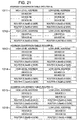
- FIG. 20 shows the contents of the routing tables (routing tables 1001, 1002, and 1003) of router A, router B, and router C (router 11, router 12, and router 13, respectively).
- FIG. 21 shows the contents of the address conversion tables (address conversion tables 1011-1016) of router A, router B, and router C (router 11, router 12, and router 13, respectively). Because the address conversion table is provided for each subnet connected to each router, the router has two address conversion tables.
- the router 22 shows the contents of the device information tables (device information tables 1021-1026) of router A, router B, and router C (router 11, router 12, and router 13, respectively). Because the device information table is provided for each subnet connected to each router, the router also has two device information tables. Now, assume that the device 3 has the API conversion table 100 shown in FIG. 6, the routing table 120 shown in FIG. 8, and the address conversion table 130 shown in FIG. 9. Also assume that the device 6 has the local device information table 110 whose contents are shown in FIG. 7 and that part of the contents is already in the device information tables 1024 and 1025 of the routers B and C shown in FIG. 22.
- air conditioner 2 that is the identifier of the destination device 6 and inquiry data created according to the format of the data storage area 330 shown in FIG. 11 are passed from the application to the API conversion unit 63.
- the API conversion unit 63 uses the received "air conditioner 2" that is the identifier of the destination device and the API conversion table 100 to get the high-level address 0h3002 of the destination device and issues a transmission request to the transmission unit 61.
- the transmission unit 61 gets destination subnet "3" from the high-level address 0h3002 of the destination device, gets the high-level address 0h20AA of the router, via which the request is to be sent, from the routing table 120 shown in FIG.
- the reception unit 62 starts the router processing shown in FIG. 17. First, because the destination subnet of the message is 3, the reception unit 62 finds that the message is addressed to the subnet of its own and then checks if the router can respond to the message on behalf of the destination device. That is, the reception unit finds, from the contents of the message, that the inquiry is about the device type of the device 6. In addition, the reception unit finds that the requested content is included in the device information table 1024 of its own. Because the router can respond to the message on behalf of the destination device, the reception unit reads the device type of "2" of the requested device 6 (device C1), creates response data according to the format of the data storage area 330 shown in FIG.
- the transmission unit 61 gets the destination subnet value of "2" from the high-level address 0h2003 of the destination device, finds that the message is addressed to the subnet of its own from the routing table 1002 shown in FIG. 20 (the value of "0" indicates the subnet of its own).
- the transmission unit 61 gets the low-level address of the transmission destination device 3 (device B1) from the address conversion table 1013 shown in FIG. 21, creates a message according to the high-level protocol header format shown in FIG. 11, and then issues the transmission request to the low-level protocol processing unit 53 to transmit the response message to the device 3.
- response processing for the response message is performed according to the steps shown in FIG. 15, and device type of the device 6 is returned to the source application as the response data.
- the present invention described above allows other devices to get information on the device 6 regardless of the transmission reliability of the network to which the device 6 is connected. In other words, even when the network reliability is low, or the device 6 is temporarily a hidden terminal, or the device 6 is not always ready for communication, information as to what kind of device is used in the system may be obtained more reliably.
- the present invention eliminates the need for the target device to perform response processing, thus decreasing the load of this device. Moreover, reducing the need to re-transmit messages at the time of a failure prevents the load of the network and the router from increasing.
- the present invention is particularly useful in such a system.
- device B1 is added to the configuration shown in FIG. 2.
- FIG. 23 is a PAD diagram showing the flow of processing that is executed when a device is added.
- the device 3 device B1 shown in FIG. 2 is added.
- the device 3 is added to the network and is turned on (step 401).
- the low-level address of the device 3 is set up in the method defined by the low-level communication protocol (step 402).
- the device 3 gets the NodeID of the high-level address (step 403).
- the low-level address is converted, for example, by some function.
- the device 3 uses the broadcast function of the low-level communication protocol to inquire of other devices about NetID of the subnet of it own (step 404).
- the broadcast function of the low-level communication protocol to inquire about the high-level addresses of the neighboring routers (routers 11 and 12 in FIG. 2) (step 405) and inquires of one of the routers (for example, router 11) about NetID (step 406).
- the device 3 sets the broadcast address in the destination low-level address DA according
- the device 3 sets the high-level address and the low-level of the device obtained in steps 403 and 404 in the local device information table 110 (step 407). Then, the device 3 inquires of the applications 51 and 52 about the types and status and sets this information, as well as its own device, in the local device information table 110 (step 408). Then, for all the neighboring routers (step 409), the device 3 sends a message shown in FIG. 11 to add the low-level address, high-level address, device type, and device application type of the device 3 to the device information table 140 and the address conversion table 130 of the neighboring routers with the use of the high-level address of the neighboring routers obtained in step 404 (step 410).
- the device 3 reads the routing tables 120 of the neighboring routers (step 411).
- the device 3 creates the routing table 120 for itself (step 412). That is, the device 3 creates the routing table at this time by getting the NetIDs of all the subnets in the system and finding to which neighboring router a message is to be sent in order to send it to each subnet.
- the routing tables 120 of the router 11 and the router 12, each of which is the neighboring router of the device 3 are the routing tables 1001 and 1002 shown in FIG. 20. From these routing tables, the high-level address of the neighboring router is obtained for each NetID ("2" - "5") according to the rules given below in order to create the routing table 120 such as the one shown in FIG. 8.
- the processing described above automatically sets up the routing information when a device is added to the network, thus providing the user with the plug-and-play feature that eliminates the need to set up routing information.
- each device Upon receiving this message, other devices can detect the addition of a new device immediately after it is added to the network and, from the contents of the operation start notification message, know the type of the connected device and the type of applications. This eliminates the need for other devices to directly inquire of the added device about the device type or application type, reducing the network load that is increased by the inquiries about the new device.
- each device upon receiving an operation start notification message, each device performs the processing shown in FIG. 13 to change the API conversion table 100. For example, even when a device is moved and its address changes, applications do not have to worry about the change but can continue to use the old device identifier as before.
- router C is added to the configuration shown in FIG. 2.
- FIG. 24 is a PAD diagram showing the flow of processing that is executed when a router is added.
- the following describes the processing shown in FIG. 24 wherein the router 13 (router C) shown in FIG. 2 is added.
- the router 13 is connected to the network 22 and is turned on (step 501).
- the low-level address of the router 13 on the side of the network 22 is set according to the method defined by the low-level communication protocol (step 502).
- the router 13 gets the NodeID of the high-level address on the side of the network 22 (step 503).
- the router 13 issues to other devices an inquiry about the NetID of its own subnet connected to the network 22 and gets it ("3" in this example) (step 504).
- the processing of subsequent steps 505-506 are the same as that of steps 405-406 described in FIG. 23.
- the router 13 gets the list of high-level addresses and low-level addresses of the devices connected to the connected subnet ("3" in this example) (step 507).
- the router 13 starts getting the NetID of the subnet on the side of new network 23 (step 508).
- the router 13 inquires one of the neighboring routers about the NetID list in use to get it (step 509), decides a free value as the NetID of the subnet on the side of the network 23 ("4" in this example) and, using this value, sets up the high-level address of the new subnet (step 510).
- the router 13 requests all the neighboring routers (step 511) to add its own (router 13) high-level address, low-level address, and device type to their device information tables and the address conversion tables (step 512) and, in addition, reads the routing tables 120 of the neighboring routers (step 513).
- the router 13 When the router 13 has finished reading the routing tables 120 of all the neighboring routers, it creates the routing table 120 for itself (step 514).
- the processing of step 514 is omitted here because the processing is the same as that of step 413 in FIG. 23.
- the neighboring router performs the similar setup processing for the downstream neighboring routers (on the side of the subnet other than the side on which information from the new router 13 is received). As a result, information about the connection of the new router is sent to, and its routing information is set in, all the routers. Then, router 13 creates an operation start notification message according to the message format shown in FIG. 12 and broadcasts it to other devices (step 517).
- the processing described above automatically sets up the routing information when a router is added to the network, thus providing the user with the plug-and-play feature that eliminates the need to set up routing information. That is, a router performs routing and other operations, as described above, assuming that the tables shown in FIGS. 8-10 and FIG. 20-22 have already been set up. Automatic setup that is executed when a device or a router is connected to the network automatically creates the contents of the tables, thus eliminating the need for the user to set up the tables.
- FIG. 25 is a diagram showing the configuration of the device information table maintained in a router when this function is executed.
- a device information table 600 comprises a high-level address 601, a device type 602, a device application type 603, a vendor ID 604, a product ID 605, a serial number 606, and an existence flag 607.
- the high-level address 601, device type 602, and device application type 603 are the same as those of the device information table 140 shown in FIG.
- a router which has the table described above, reads the vendor ID, product ID, and serial number from the newly added device and adds them to its own device information table when the device is connected to the subnet to which the router is connected and, at the same time, sends a message containing this information to the downstream neighboring routers.
- each neighboring router checks if the device indicated by the vendor ID, product ID, and serial number contained in the message matches one of the devices stored in its own device information table.
- the router deletes it from the table; if there is not a matching device, the router sends this message to the downstream neighboring router.
- the processing described above automatically changes the device information table even when a device is moved from one subnet to another. In this way, when a device is moved, this method immediately deletes routing information on the deleted device from the table in the router, making the routing table smaller and more accurate.
Abstract
Description
Claims (15)
- A communication apparatus connected to a plurality of communication networks, each of which has at least one device, and relaying communication information between said plurality of communication networks, comprising:a bus (1003);a receiver (1004) connected to said plurality of communication networks for receiving device information from a device connected to one of said plurality of communication networks, said device information identifying the device;a storage unit (1000) connected to said receiver (1004) through said bus (1003) for storing the device information received by said receiver (1004);a processor (1001) connected to said storage unit (1000) through said bus (1003) for creating a response in response to a request using the device information stored in said storage unit (1000), when said receiver (1004) receives said request transmitted from a device connected to a first communication network of said plurality of communication networks to a device connected to a second communication network of said plurality of communication networks, said request inquiring about a function of the device connected to said second network; anda transmitter (1004) connected to said processor (1001) through said bus (1003) and connected to said plurality of communication networks for transmitting the response to said first communication network.
- The apparatus of claim 1, whereinsaid communication apparatus is a router, andsaid transmitter (1004) transmits information related to the request to the device via the second communication network.
- The apparatus of claim 1, wherein said request is control information for controlling a device connected to one of the communication networks.
- The apparatus of claim 3, whereinsaid receiver (1004) receives a result of the control executed in the controlled device, andsaid transmitter (1004) transmits the result of the control to the first communication network.
- The apparatus of claim 1, wherein said storage unit (1000) stores the device information on other devices connected to said plurality of communication networks.
- The apparatus of claim 1, wherein said receiver (1004) receives the request transmitted from the device connected to the first communication network, and preferably also from some other communication apparatus connected to the first communication network.
- The apparatus of claim 1, wherein said receiver (1004) receives the device information of a device connected to one of said plurality of communication networks, when a connect condition of the device is changed.
- The apparatus of claim 1, wherein, when the communication apparatus connected to a third communication network is connected to the second communication network,said receiver (1004) receives a connect notification from the communication apparatus connected to the third communication network,said transmitter (1004) transmits the device information stored in said communication apparatus to the communication apparatus connected to the third communication network, based on said connect notification, andsaid receiver (1004) receives the device information stored in the communication apparatus connected to the third communication network.
- A remote control method for controlling devices in a distributed system including a plurality of communication networks interconnected though routers, said remote control method comprising the steps of:providing, by each of said routers, device information to identify the devices connected to the router through one of the communication networks;transmitting a control request inquiring about a function of a device connected to a second communication network of said plurality of communication networks, from a control apparatus connected to a first communication network of said plurality of communication networks;receiving the control request by the router;transmitting, by said router, control information related to the control request to the device connected to said second network;controlling the device connected to the second communication network in accordance with the control information;creating, by the router, a response which is a result of said control using the device information;transmitting, by the router, the response to the control apparatus via the first communication network; andreceiving the response by the control apparatus, through the first communication network.
- The method of claim 9, wherein, when a connect condition of devices to said plurality of networks is changed, said router receives the device information on the changed devices.
- The invention of claim 7 or 10, wherein the change in the connect condition includes adding a new device to one of the communication networks, and/or moving the device from one network to another, and/or removing the device from one of the communication networks.
- The method of claim 9, further comprising the steps of:recognising that the router is connected to a new network; andtransmitting, by the newly connected router, the device information stored in said newly-connected router to other routers connected to said newly connected network in response to said step of recognition.
- The invention of claim 1 or 9, wherein said device information includes function information identifying the function of the device, and/or address information showing an address of the device in the communication networks.
- The invention of claim 13, wherein said function information includes information showing a type of the device and/or information showing a type of an application program of the device.
- The method of claim 14, wherein said step of providing device information provides not only the device information on the devices connected to the first network but also the device information on other devices connected to said plurality of networks.
Applications Claiming Priority (2)
| Application Number | Priority Date | Filing Date | Title |
|---|---|---|---|
| JP4267199 | 1999-02-22 | ||
| JP04267199A JP3823585B2 (en) | 1999-02-22 | 1999-02-22 | Device network connection method and router device |
Publications (2)
| Publication Number | Publication Date |
|---|---|
| EP1039725A2 true EP1039725A2 (en) | 2000-09-27 |
| EP1039725A3 EP1039725A3 (en) | 2004-11-17 |
Family
ID=12642504
Family Applications (1)
| Application Number | Title | Priority Date | Filing Date |
|---|---|---|---|
| EP00101457A Withdrawn EP1039725A3 (en) | 1999-02-22 | 2000-01-25 | Communication apparatus and remote control method |
Country Status (2)
| Country | Link |
|---|---|
| EP (1) | EP1039725A3 (en) |
| JP (1) | JP3823585B2 (en) |
Cited By (8)
| Publication number | Priority date | Publication date | Assignee | Title |
|---|---|---|---|---|
| EP1265405A1 (en) * | 2000-12-27 | 2002-12-11 | Matsushita Electric Industrial Co., Ltd. | Routing processing and method for home bus system |
| FR2828357A1 (en) * | 2001-08-01 | 2003-02-07 | Canon Europa Nv | Audio-video domestic network remote control processing method having first signal specific nodes address predetermined function processing and second signal transparently node transported where target signal recognized otherwise ignored. |
| EP1294159A2 (en) * | 2001-09-13 | 2003-03-19 | PacketLight Networks Ltd. | Method for assigning network addresses |
| WO2003067813A2 (en) * | 2002-01-15 | 2003-08-14 | Matsushita Electric Industrial Co., Ltd. | Routing device and startup method thereof in a home network |
| EP1521401A1 (en) * | 2003-10-01 | 2005-04-06 | Merten GmbH & Co. KG | System in Buildingsystem Industry and Method for Configuration thereof |
| EP1953469A2 (en) * | 2007-02-05 | 2008-08-06 | LG Electronics Inc. | Integrated management system and method using enhanced remote communication protocal for controlling multi-type air conditioners |
| US7676824B2 (en) | 2001-08-01 | 2010-03-09 | Canon Europa Nv | Method for the processing of remote control signals within a home audiovisual network, corresponding signal, devices and computer program |
| US7742856B2 (en) | 2005-08-04 | 2010-06-22 | Denso Corporation | Vehicle communication method and system, function identifying system, and electronic control unit |
Families Citing this family (6)
| Publication number | Priority date | Publication date | Assignee | Title |
|---|---|---|---|---|
| US6801942B1 (en) * | 2000-09-15 | 2004-10-05 | Robert Bosch Gmbh | Apparatus, method and system for remotely accessing and/or controlling can node arrangements, including vehicle electronic control units, during vehicle operation |
| KR100493898B1 (en) | 2003-04-16 | 2005-06-10 | 삼성전자주식회사 | Network device, system and method for providing list of controlled device |
| KR100670661B1 (en) * | 2004-12-24 | 2007-01-17 | 엔에이치엔(주) | Communication network system of bus network structure and message rounting method using the system |
| JP4799005B2 (en) * | 2005-02-10 | 2011-10-19 | 富士通株式会社 | Information processing device |
| JP5692013B2 (en) * | 2011-11-14 | 2015-04-01 | 株式会社デンソー | Communication control device |
| JP7399029B2 (en) | 2020-06-03 | 2023-12-15 | 三菱電機株式会社 | Gateway device, communication method, and program |
Family Cites Families (2)
| Publication number | Priority date | Publication date | Assignee | Title |
|---|---|---|---|---|
| JP3586548B2 (en) * | 1997-01-10 | 2004-11-10 | シャープ株式会社 | Communication method, communication system, computer-readable recording medium storing communication program, and communication device |
| US6167438A (en) * | 1997-05-22 | 2000-12-26 | Trustees Of Boston University | Method and system for distributed caching, prefetching and replication |
-
1999
- 1999-02-22 JP JP04267199A patent/JP3823585B2/en not_active Expired - Fee Related
-
2000
- 2000-01-25 EP EP00101457A patent/EP1039725A3/en not_active Withdrawn
Non-Patent Citations (1)
| Title |
|---|
| None * |
Cited By (15)
| Publication number | Priority date | Publication date | Assignee | Title |
|---|---|---|---|---|
| EP1265405A1 (en) * | 2000-12-27 | 2002-12-11 | Matsushita Electric Industrial Co., Ltd. | Routing processing and method for home bus system |
| EP1265405A4 (en) * | 2000-12-27 | 2008-02-13 | Matsushita Electric Ind Co Ltd | Routing processing and method for home bus system |
| US7676824B2 (en) | 2001-08-01 | 2010-03-09 | Canon Europa Nv | Method for the processing of remote control signals within a home audiovisual network, corresponding signal, devices and computer program |
| FR2828357A1 (en) * | 2001-08-01 | 2003-02-07 | Canon Europa Nv | Audio-video domestic network remote control processing method having first signal specific nodes address predetermined function processing and second signal transparently node transported where target signal recognized otherwise ignored. |
| EP1294159A2 (en) * | 2001-09-13 | 2003-03-19 | PacketLight Networks Ltd. | Method for assigning network addresses |
| EP1294159A3 (en) * | 2001-09-13 | 2003-08-27 | PacketLight Networks Ltd. | Method for assigning network addresses |
| WO2003067813A2 (en) * | 2002-01-15 | 2003-08-14 | Matsushita Electric Industrial Co., Ltd. | Routing device and startup method thereof in a home network |
| WO2003067813A3 (en) * | 2002-01-15 | 2004-04-15 | Matsushita Electric Ind Co Ltd | Routing device and startup method thereof in a home network |
| CN1326367C (en) * | 2002-01-15 | 2007-07-11 | 松下电器产业株式会社 | A routing device and startup method thereof |
| US7707306B2 (en) | 2002-01-15 | 2010-04-27 | Panasonic Corporation | Routing device for connecting multiple physically discrete networks into a single system and startup method thereof |
| EP1521401A1 (en) * | 2003-10-01 | 2005-04-06 | Merten GmbH & Co. KG | System in Buildingsystem Industry and Method for Configuration thereof |
| US7742856B2 (en) | 2005-08-04 | 2010-06-22 | Denso Corporation | Vehicle communication method and system, function identifying system, and electronic control unit |
| DE102006036322B4 (en) * | 2005-08-04 | 2015-03-12 | Denso Corporation | Vehicle communication method and system, function identification system and electronic control unit |
| EP1953469A2 (en) * | 2007-02-05 | 2008-08-06 | LG Electronics Inc. | Integrated management system and method using enhanced remote communication protocal for controlling multi-type air conditioners |
| EP1953469A3 (en) * | 2007-02-05 | 2012-05-02 | LG Electronics, Inc. | Integrated management system and method using enhanced remote communication protocal for controlling multi-type air conditioners |
Also Published As
| Publication number | Publication date |
|---|---|
| JP2000244549A (en) | 2000-09-08 |
| EP1039725A3 (en) | 2004-11-17 |
| JP3823585B2 (en) | 2006-09-20 |
Similar Documents
| Publication | Publication Date | Title |
|---|---|---|
| US8103784B2 (en) | Communication device and communication control method using efficient echonet address determination scheme | |
| US7339895B2 (en) | Gateway device and control method for communication with IP and IPV6 protocols | |
| KR100605177B1 (en) | Connection handling apparatus of home network management system | |
| EP1039725A2 (en) | Communication apparatus and remote control method | |
| US7385981B2 (en) | Apparatus for converting internet protocol address and home network system using the same | |
| US5687320A (en) | Indirect method for network peripheral automated detection | |
| JP3725165B2 (en) | Method for initializing a wireless packet hopping network | |
| KR101810587B1 (en) | System and method for automatic configuration of master/slave devices on a network | |
| US8094655B2 (en) | Communication scheme with arbitration mechanism for cases of address initialization and server setting | |
| US20030016682A1 (en) | Gateway enabling data communication between devices having different middlewares | |
| US20020124007A1 (en) | Network server and database therein | |
| US20020169886A1 (en) | Communication device and communication control device for enabling operation of control protocol for one network on other types of networks | |
| US20010033554A1 (en) | Proxy-bridge connecting remote users to a limited connectivity network | |
| US7707306B2 (en) | Routing device for connecting multiple physically discrete networks into a single system and startup method thereof | |
| WO2006065101A1 (en) | Method for balancing load among subsystems in communication network system of bus network structure | |
| JPH10285204A (en) | Interconnected ethernet and 1394-network | |
| KR100455868B1 (en) | Communication system and communication control apparatus and method | |
| KR100902841B1 (en) | Home network system and method for home networking | |
| US9432475B2 (en) | Communication network system of bus network structure and method for transmitting and receiving data using the system | |
| US6961775B2 (en) | Method, system, and program for enabling communication between devices using different address formats | |
| KR101885618B1 (en) | Method for automatically connecting ip based devices and the apparatus supporting the same | |
| JP3432449B2 (en) | Communication control apparatus and method | |
| JPH0758771A (en) | Address managing device | |
| JP3437746B2 (en) | Communication control device and communication control method | |
| JPH10200526A (en) | Method for managing state of ip node |
Legal Events
| Date | Code | Title | Description |
|---|---|---|---|
| PUAI | Public reference made under article 153(3) epc to a published international application that has entered the european phase |
Free format text: ORIGINAL CODE: 0009012 |
|
| AK | Designated contracting states |
Kind code of ref document: A2 Designated state(s): DE FR GB |
|
| PUAL | Search report despatched |
Free format text: ORIGINAL CODE: 0009013 |
|
| AK | Designated contracting states |
Kind code of ref document: A3 Designated state(s): DE FR GB |
|
| 17P | Request for examination filed |
Effective date: 20041130 |
|
| 17Q | First examination report despatched |
Effective date: 20050304 |
|
| AKX | Designation fees paid |
Designated state(s): DE FR GB |
|
| 17Q | First examination report despatched |
Effective date: 20050304 |
|
| STAA | Information on the status of an ep patent application or granted ep patent |
Free format text: STATUS: THE APPLICATION IS DEEMED TO BE WITHDRAWN |
|
| 18D | Application deemed to be withdrawn |
Effective date: 20070123 |