EP1039303A1 - Method for adjusting sensitivity of acceleration sensor - Google Patents
Method for adjusting sensitivity of acceleration sensor Download PDFInfo
- Publication number
- EP1039303A1 EP1039303A1 EP00302353A EP00302353A EP1039303A1 EP 1039303 A1 EP1039303 A1 EP 1039303A1 EP 00302353 A EP00302353 A EP 00302353A EP 00302353 A EP00302353 A EP 00302353A EP 1039303 A1 EP1039303 A1 EP 1039303A1
- Authority
- EP
- European Patent Office
- Prior art keywords
- acceleration
- piezoelectric elements
- sensor device
- acceleration sensor
- pair
- Prior art date
- Legal status (The legal status is an assumption and is not a legal conclusion. Google has not performed a legal analysis and makes no representation as to the accuracy of the status listed.)
- Withdrawn
Links
- 230000001133 acceleration Effects 0.000 title claims abstract description 121
- 238000000034 method Methods 0.000 title claims abstract description 45
- 230000035945 sensitivity Effects 0.000 title claims abstract description 41
- 230000005284 excitation Effects 0.000 claims description 97
- 238000009966 trimming Methods 0.000 claims description 81
- 239000000463 material Substances 0.000 claims description 27
- 239000000758 substrate Substances 0.000 claims description 14
- 230000010287 polarization Effects 0.000 description 14
- 238000010586 diagram Methods 0.000 description 11
- 239000003990 capacitor Substances 0.000 description 9
- 230000007423 decrease Effects 0.000 description 4
- 230000003247 decreasing effect Effects 0.000 description 3
- 238000001514 detection method Methods 0.000 description 3
- 230000010355 oscillation Effects 0.000 description 3
- 238000005259 measurement Methods 0.000 description 2
- BASFCYQUMIYNBI-UHFFFAOYSA-N platinum Chemical compound [Pt] BASFCYQUMIYNBI-UHFFFAOYSA-N 0.000 description 2
- 238000005452 bending Methods 0.000 description 1
- 230000002950 deficient Effects 0.000 description 1
- PCHJSUWPFVWCPO-UHFFFAOYSA-N gold Chemical compound [Au] PCHJSUWPFVWCPO-UHFFFAOYSA-N 0.000 description 1
- 229910052737 gold Inorganic materials 0.000 description 1
- 239000010931 gold Substances 0.000 description 1
- 230000005389 magnetism Effects 0.000 description 1
- 238000004519 manufacturing process Methods 0.000 description 1
- 238000012986 modification Methods 0.000 description 1
- 230000004048 modification Effects 0.000 description 1
- 229910052697 platinum Inorganic materials 0.000 description 1
- 229910052709 silver Inorganic materials 0.000 description 1
- 239000004332 silver Substances 0.000 description 1
- 238000005476 soldering Methods 0.000 description 1
Images


Classifications
-
- G—PHYSICS
- G01—MEASURING; TESTING
- G01P—MEASURING LINEAR OR ANGULAR SPEED, ACCELERATION, DECELERATION, OR SHOCK; INDICATING PRESENCE, ABSENCE, OR DIRECTION, OF MOVEMENT
- G01P21/00—Testing or calibrating of apparatus or devices covered by the preceding groups
-
- G—PHYSICS
- G01—MEASURING; TESTING
- G01P—MEASURING LINEAR OR ANGULAR SPEED, ACCELERATION, DECELERATION, OR SHOCK; INDICATING PRESENCE, ABSENCE, OR DIRECTION, OF MOVEMENT
- G01P15/00—Measuring acceleration; Measuring deceleration; Measuring shock, i.e. sudden change of acceleration
- G01P15/02—Measuring acceleration; Measuring deceleration; Measuring shock, i.e. sudden change of acceleration by making use of inertia forces using solid seismic masses
- G01P15/08—Measuring acceleration; Measuring deceleration; Measuring shock, i.e. sudden change of acceleration by making use of inertia forces using solid seismic masses with conversion into electric or magnetic values
- G01P15/09—Measuring acceleration; Measuring deceleration; Measuring shock, i.e. sudden change of acceleration by making use of inertia forces using solid seismic masses with conversion into electric or magnetic values by piezoelectric pick-up
- G01P15/0922—Measuring acceleration; Measuring deceleration; Measuring shock, i.e. sudden change of acceleration by making use of inertia forces using solid seismic masses with conversion into electric or magnetic values by piezoelectric pick-up of the bending or flexing mode type
-
- G—PHYSICS
- G01—MEASURING; TESTING
- G01P—MEASURING LINEAR OR ANGULAR SPEED, ACCELERATION, DECELERATION, OR SHOCK; INDICATING PRESENCE, ABSENCE, OR DIRECTION, OF MOVEMENT
- G01P15/00—Measuring acceleration; Measuring deceleration; Measuring shock, i.e. sudden change of acceleration
- G01P15/18—Measuring acceleration; Measuring deceleration; Measuring shock, i.e. sudden change of acceleration in two or more dimensions
-
- G—PHYSICS
- G01—MEASURING; TESTING
- G01P—MEASURING LINEAR OR ANGULAR SPEED, ACCELERATION, DECELERATION, OR SHOCK; INDICATING PRESENCE, ABSENCE, OR DIRECTION, OF MOVEMENT
- G01P15/00—Measuring acceleration; Measuring deceleration; Measuring shock, i.e. sudden change of acceleration
- G01P15/02—Measuring acceleration; Measuring deceleration; Measuring shock, i.e. sudden change of acceleration by making use of inertia forces using solid seismic masses
- G01P15/08—Measuring acceleration; Measuring deceleration; Measuring shock, i.e. sudden change of acceleration by making use of inertia forces using solid seismic masses with conversion into electric or magnetic values
- G01P2015/0805—Measuring acceleration; Measuring deceleration; Measuring shock, i.e. sudden change of acceleration by making use of inertia forces using solid seismic masses with conversion into electric or magnetic values being provided with a particular type of spring-mass-system for defining the displacement of a seismic mass due to an external acceleration
- G01P2015/0822—Measuring acceleration; Measuring deceleration; Measuring shock, i.e. sudden change of acceleration by making use of inertia forces using solid seismic masses with conversion into electric or magnetic values being provided with a particular type of spring-mass-system for defining the displacement of a seismic mass due to an external acceleration for defining out-of-plane movement of the mass
- G01P2015/084—Measuring acceleration; Measuring deceleration; Measuring shock, i.e. sudden change of acceleration by making use of inertia forces using solid seismic masses with conversion into electric or magnetic values being provided with a particular type of spring-mass-system for defining the displacement of a seismic mass due to an external acceleration for defining out-of-plane movement of the mass the mass being suspended at more than one of its sides, e.g. membrane-type suspension, so as to permit multi-axis movement of the mass
-
- Y—GENERAL TAGGING OF NEW TECHNOLOGICAL DEVELOPMENTS; GENERAL TAGGING OF CROSS-SECTIONAL TECHNOLOGIES SPANNING OVER SEVERAL SECTIONS OF THE IPC; TECHNICAL SUBJECTS COVERED BY FORMER USPC CROSS-REFERENCE ART COLLECTIONS [XRACs] AND DIGESTS
- Y10—TECHNICAL SUBJECTS COVERED BY FORMER USPC
- Y10T—TECHNICAL SUBJECTS COVERED BY FORMER US CLASSIFICATION
- Y10T29/00—Metal working
- Y10T29/42—Piezoelectric device making
-
- Y—GENERAL TAGGING OF NEW TECHNOLOGICAL DEVELOPMENTS; GENERAL TAGGING OF CROSS-SECTIONAL TECHNOLOGIES SPANNING OVER SEVERAL SECTIONS OF THE IPC; TECHNICAL SUBJECTS COVERED BY FORMER USPC CROSS-REFERENCE ART COLLECTIONS [XRACs] AND DIGESTS
- Y10—TECHNICAL SUBJECTS COVERED BY FORMER USPC
- Y10T—TECHNICAL SUBJECTS COVERED BY FORMER US CLASSIFICATION
- Y10T29/00—Metal working
- Y10T29/49—Method of mechanical manufacture
- Y10T29/49002—Electrical device making
- Y10T29/49007—Indicating transducer
Definitions
- the present invention relates to a method for adjusting the sensitivity of an acceleration detecting device capable of detecting at least one of components, which respectively correspond to the directions of three orthogonal axes, namely, X-axis, Y-axis, and Z-axis, of an externally acting acceleration, which acts thereon.
- a sensor having a plurality of piezoelectric elements mounted on a flexible plate mounted on a flexible substrate having an operating member is disclosed in the Japanese Unexamined Patent Publication No. 5-26744.
- This sensor is configured so that the flexible substrate deforms according to a physical quantity externally acting on the operating member.
- the direction and magnitude of the externally acting physical quantity are detected by a single acceleration detecting device in a three-dimensional manner on the basis of electric charges that are produced in the piezoelectric elements according to strain due to the deformation of the flexible substrate.
- FIG. 8 is a perspective diagram illustrating the concept of a coordinate system for a three-axis sensor.
- an acceleration sensor device which has an operating member as a weight
- an inertial force f acts on a weight 1 in a direction opposite to the direction of the acceleration a .
- This inertial force f causes the deformation of a flexible substrate 3 put on the weight 1 and supports 2.
- the aforementioned acceleration detecting device is configured so that components of the externally acting acceleration, which respectively correspond to the directions of X-axis, Y-axis, and Z-axis, are detected by a single acceleration detecting device as components.
- a single acceleration detecting device as components.
- the strain due to the deformation occurs not only in the piezoelectric element 20x for detecting X-axis component of the acceleration, but in the piezoelectric element 20y (not shown in FIG. 9B) for detecting Y-axis component of the acceleration. Consequently, electric charges are produced in the piezoelectric elements 20x and 20y.
- the weight 1 does not undergo the influence of the acceleration only in the directions of X-axis and Y-axis, so that it is necessary to prevent electric outputs of the electric charges produced in the piezoelectric elements 20x and 20y from being electrically outputted therefrom.
- the aforementioned acceleration detecting device employs a method of electrically canceling the produced charges by configuring the pair of piezoelectric elements.
- a piezoelectric device which corresponds to each of X-axis, Y-axis, and Z-axis, of the acceleration detecting device comprises at least one pair of piezoelectric elements placed at positions that are symmetric with respect to the weight 1. Because of the symmetric positions of the pair of piezoelectric elements with respect to the weight 1, the amounts of strain of (that is, the amounts of the electric charges respectively produced in) these piezoelectric elements of the pair are almost equal to each other. Furthermore, as shown in FIGS.
- the quantities of electric charges to be produced in the piezoelectric elements of the pair are not equal to each other owing to defective conditions at the time of forming the piezoelectric elements, for instance, variation in the electrode area of the piezoelectric elements, variation in the dielectric constant of the piezoelectric elements, a deviation of the position of the weight, and variation in deformation caused by the bending of the flexible substrate.
- the electric charges produced in the piezoelectric elements of the pair are not completely canceled but outputted therefrom as electrical signals.
- the sensitivity in the direction of X-axis is indicated despite the fact that the acceleration sensor device undergoes the influence of the acceleration only in the direction of Z-axis (hereunder, such sensitivity will be referred to as "another axis noise").
- the present invention is accomplished in view of the aforementioned circumstances.
- the present invention provides a method for adjusting the sensitivity of an acceleration detecting device, according to which electrical outputs of piezoelectric elements of a pair of an acceleration detecting device are canceled by making the amounts of electric charges, which are respectively produced in a pair of piezoelectric elements placed at positions symmetric with respect to a weight, equal to each other, to thereby suppress the aforementioned another axis noise.
- the acceleration sensor device having an acceleration detecting device may comprises a weight, a support that is installed around said weight and has a hollow portion, a flexible substrate put on the support so that the weight is suspended in the hollow portion of said support, and a pair of piezoelectric elements.
- the electrostatic capacity may be changed so that the difference between the absolute values of excitation outputs respectively generated in the piezoelectric elements of the acceleration detecting device becomes small when the acceleration sensor device is oscillated in Z-direction. If the acceleration detecting device is adapted to detect an acceleration component in Z-direction, the electrostatic capacity may be changed so that the difference between the absolute values of excitation outputs respectively generated in the piezoelectric elements of the acceleration detecting device becomes small when the acceleration sensor device is oscillated in X-direction or Y-direction.
- two pairs of the piezoelectric elements may be provided in said acceleration sensor device correspondingly to two orthogonal axes.
- three pairs of the piezoelectric elements may be provided in said acceleration sensor device correspondingly to three orthogonal axes.
- the electrostatic capacity may be changed so that the shapes of the piezoelectric elements are symmetric with respect to X-axis and so that the difference between the absolute values of excitation outputs respectively generated in the piezoelectric elements of the acceleration detecting device becomes small when the acceleration sensor device is oscillated in Z-direction.
- the electrostatic capacity may be changed so that the difference between the absolute values of excitation outputs respectively generated in the piezoelectric elements of the acceleration detecting device becomes small when the acceleration sensor device is oscillated in Z-direction.
- which of electrodes respectively corresponding to the piezoelectric elements of the pair for detecting an acceleration component in Z-direction should undergo trimming processing may be determined according to whether or not an excitation output generated in the piezoelectric elements for detecting an acceleration component in Z-direction and an excitation output generated in the piezoelectric elements for detecting an acceleration component in X-direction are different in sign from each other when the acceleration sensor device is oscillated in X-direction, and according to whether or not an excitation output generated in the piezoelectric elements for detecting an acceleration component in Z-direction and an excitation output generated in the piezoelectric elements for detecting an acceleration component in Y-direction are different in sign from each other when the acceleration sensor device is oscillated in Y-direction.
- an adjusting capacitance which is connected to an electrode corresponding to each of the piezoelectric elements of the pair, may be formed at a portion, which corresponds to the support, of a piezoelectric material of a corresponding one of the piezoelectric elements of the pair.
- the trimming processing may be performed on the adjusting capacitance instead of performing the trimming processing on the electrode.
- the adjusting capacitance is connected to an electrode corresponding to the piezoelectric element, which has a larger excitation output, of the pair between the piezoelectric elements of the pair, whose excitation outputs are made to be different from each other.
- a part of the electrode may be placed at a portion, which corresponds to said support or to a operating member, of a piezoelectric material corresponding to one of the piezoelectric element of the pair.
- the trimming processing may be performed at the part of the electrode.
- an electrode corresponding to the piezoelectric element, which has a larger excitation output, of the pair between the pair of the piezoelectric elements, whose excitation outputs are made to be different from each other has a part placed on a portion, which corresponds to the support or to the operating member, of the piezoelectric material.
- the electrode may be formed like a comb and may have bottom land portions each formed on the portion, which corresponds to the support or to the operating member, of the piezoelectric material, and may have tooth-like portions each projected from corresponding one of the bottom land portions and each extended from a portion, which corresponds to the hollow portion, of the piezoelectric material.
- the bottom land portions each provided between adjacent ones of said tooth-like portions maybe cut by performing trimming processing.
- the trimming processing may be performed on a portion, which is provided at the side of the operating member or of the support, of the electrode along the circumference of a circle, the center of which is an origin (O).
- the trimming processing may be performed on the electrode along a line segment connecting an origin (O) to a point provided on the circumference of a circle, the center of which is the origin (O).
- the electric outputs of the piezoelectric elements are changed by varying the electrostatic capacity of the acceleration sensor device.
- the term "piezoelectric element” is defined as a portion of the piezoelectric material, which is sandwiched between upper and lower electrodes in the upward or downward direction thereof.
- the trimming processing is performed thereon so that the shapes of the electrodes of the pair are axially symmetric with respect to a same straight line passing through the center of the hollow portion.
- the trimming processing is performed on thereon so that the difference between the absolute values of excitation or oscillation outputs respectively generated in the piezoelectric elements of the pair becomes small when the device is oscillated in Z-direction.
- the trimming processing is performed on thereon so that the difference between the absolute values of excitation or oscillation outputs respectively generated in the piezoelectric elements of the pair becomes small when the device is oscillated in X-direction or Y-direction.
- the trimming processing is performed on thereon so that the difference between the absolute values of excitation or oscillation outputs respectively generated in the piezoelectric elements of the pair becomes small when the device is oscillated in X-direction or Y-direction.
- the difference between the absolute values of excitation outputs is not more than 5 %.
- the trimming processing is performed on the electrodes corresponding to X-direction so that the shape of the electrodes 13 corresponding to X-direction is axially symmetric with respect to X-axis, as illustrated in FIG. 3B, and so that the difference between the absolute values of the excitation outputs generated respectively in the elements of the pair corresponding to X-direction becomes small when the device is oscillated in Z-direction.
- the elements corresponding to X-direction is adapted to detect only a component force in X-direction.
- the purpose of making the shape of the pair of the electrodes 13 corresponding to X-direction axially symmetric with respect to X-axis is to reduce noises due to the component force in Y-direction. That is, the direction of strain caused in the piezoelectric materials when oscillated in Y-direction varies with and has opposite signs respectively corresponding to the sides of X-axis.
- the direction of polarization of one of the electrodes 13 of the pair corresponding to X-direction is the same direction of polarization.
- the signs of the electric charges are determined by the direction of the deformation. Therefore, the electric charge generated in each of the electrodes of the pair can be approximately zero. Consequently, noises due to the component force in Y-direction can be decreased.
- the purpose of making the difference between the absolute values of the excitation outputs generated in the elements of the pair corresponding to X-direction small is to reduce noises caused owing to the component force in Z-direction in the elements corresponding to X-direction.
- the signs or polarities of the electric charges produced in the elements are determined by a product of the direction of polarization and the direction of deformation of the elements. Further, the directions of polarization of the elements of the pair corresponding to X-direction are opposite to each other.
- the excitation output of the elements is given by (Q/C) where Q denotes an amount of electric charge produced in each of the elements, and C designates the capacitance thereof.
- the signs of the excitation outputs of the elements of the pair corresponding to X-direction are different from each other. Consequently, the excitation output of the entirety of the device corresponding to X-direction should be canceled. Namely, the device corresponding to X-direction should generate no excitation output. However, actually, there is a difference between the absolute values of the excitation outputs of the elements owing to the difference in the amount of produced electric charge between the elements of the pair corresponding to X-direction. This results in generation of noises corresponding to the other axes.
- the amount of electric charge produced in one 13a (hereunder sometimes indicated by "X1”) of the elements of the pair corresponding to X-direction before the trimming is Q
- the amount of electric charge produced in the other element 13b (hereunder sometimes indicated by "X2”) is -(Q + ⁇ Q).
- the excitation output of the element X1 (13a) is Q/C1 where C1 designates the capacitance of the element X1.
- the excitation output of the element X2 (13b) is - (Q + ⁇ Q)/(C2 + ⁇ C) where (C2+ ⁇ C) denotes the capacitance of the element X2.
- the total amount of electric charge generated in the entire device corresponding to X-direction is - ⁇ Q.
- the capacitance of the entire device is C1+C2+ ⁇ C . Consequently, noises corresponding to the excitation output, which is - ⁇ Q/(C1 + C2 + ⁇ C) , of the entire device corresponding to X-direction are produced.
- the amount of electric charge generated in and the capacitance of the device corresponding to X-direction are adjusted by performing the trimming processing.
- the difference between the absolute values of the excitation outputs of the elements of the pair of the device corresponding to X-direction are made to be small. Consequently, when oscillated in Z-direction, the excitation output of the entire device corresponding to X-direction is 0. Further, the noises due to the component force in Z-direction is reduced.
- the trimming processing is performed according to the measurement values thereof. Acceleration-in-X-direction Detecting Device X1 X2 Total Polarization Direction + - Deformation Direction + + Produced Charge Q -Q 0 Capacitance C1 C2 C1+C2 Excitation Output Q/C1 -Q/C2 0
- the trimming processing is performed on the electrodes corresponding to Y-direction so that the shape of the electrodes corresponding to Y-direction is axially symmetric with respect to Y-axis, and so that the difference between the absolute values of the excitation outputs generated respectively in the elements of the pair corresponding to Y-direction becomes small when the device is oscillated in Z-direction.
- the elements corresponding to Y-direction is adapted to detect only a component force in Y-direction.
- the purpose of making the shape of the pair of the electrodes corresponding to Y-direction axially symmetric with respect to Y-axis is to reduce noises due to the component force in X-direction.
- the purpose of making the difference between the absolute values of the excitation outputs generated in the elements of the pair corresponding to Y-direction small when oscillated in Z-direction is to reduce noises caused owing to the component force in Z-direction in the elements corresponding to Y-direction.
- the noises caused corresponding to the axes other than the excitation axis can be reduced. Because the electrodes of the pair corresponding to Y-direction are separated from each other, the amount of electric charges generated in and the capacitance of the elements of the pair of the device corresponding to Y-axis can be individually measured. Thus, the trimming processing is performed according to the measurement values thereof.
- the trimming processing is performed on the electrodes corresponding to Z-direction so that the difference between the absolute values of the excitation outputs generated respectively in the elements of the pair corresponding to X-direction or Y-direction becomes small when the device is oscillated in X-direction or Y-direction.
- the purpose of this is to reduce noises produced owing to the component force in X-direction or Y-direction in the elements corresponding to Z-direction.
- the signs or polarities of the electric charges produced in the elements are determined, as described above, by a product of the direction of polarization and the direction of deformation of the elements. Further, the directions of polarization of the elements of the pair corresponding to Z-direction are the same one. When oscillated in X-direction or Y-direction, the directions of deformations caused in the piezoelectric materials of the elements of the pair corresponding to Z-direction are opposite to each other. As a result, the electric charges produced in the elements of the pair corresponding to Z-direction have opposite sign or polarities. Therefore, the signs of the excitation outputs of the elements of the pair corresponding to Z-direction should be canceled.
- the device corresponding to Z-direction should generate no excitation output.
- there is a difference between the absolute values of the excitation outputs of the elements owing to the difference in the amount of produced electric charge between the elements of the pair corresponding to Z-direction.
- the amount of electric charge produced in one 15b (hereunder sometimes indicated by "Z1") of the elements of the pair corresponding to Z-direction before the trimming is Q'
- the amount of electric charge produced in the other element 15a (hereunder sometimes indicated by "Z2”) is -(Q' + ⁇ Q).
- the excitation output of the element Z1 (15b) is Q'/C3 where C3 designates the capacitance of the element Z1.
- the excitation output of the element Z2 (15a) is - (Q' + ⁇ Q)/(C4 + ⁇ C) where (C4+ ⁇ C) denotes the capacitance of the element Z2. Therefore, the total amount of electric charge generated in the entire device corresponding to Z-direction is - ⁇ Q.
- the capacitance of the entire device is C3+C4+ ⁇ C . Consequently, noises corresponding to the excitation output, which is - ⁇ Q/(C3 + C4 + ⁇ C) , of the entire device corresponding to Z-direction are produced.
- Acceleration-in-Z-direction Detecting Device Acceleration-in-X-direction Detecting Device Z1 Z2 Total X1 X2 Total Polarization Direction + + + - Deformation Direction + - + - Produced Charge Q' -(Q'+ ⁇ Q) - ⁇ Q Q Q 2Q Capacitance C3 C4+ ⁇ C C3+C4+ ⁇ C C1 C2 C1+C2 Excitation Output Q'/C3 -(Q'+ ⁇ Q)/(C4+ ⁇ C) - ⁇ Q/(C3+C4+ ⁇ C) Q/C1 Q/C2 2Q/(C1+C2)
- the amount of electric charge generated in and the capacitance of the device corresponding to Z-direction are adjusted by performing the trimming processing on the electrodes corresponding to Z-direction.
- the difference between the absolute values of the excitation outputs of the elements of the pair of the device corresponding to Z-direction are made to be small. Consequently, when oscillated in X-direction or Y-direction, the excitation output of the entire device corresponding to Z-direction is 0.
- the noises due to the component force in X-direction or Y-direction is reduced.
- the trimming processing of the electrodes corresponding to Z-direction is performed on edge portions thereof in the vicinity of the electrodes 13 corresponding to X-direction, as illustrated in FIG. 4B, when noises produced due to the component force in X-direction are reduced.
- the reason for this is as follows. That is, when oscillated in X-direction, deformation caused in the electrodes corresponding to Z-axis is large in the vicinity of X-axis, while deformation caused in these electrodes is small, namely, almost no deformation caused therein in the proximity of Y-axis. Therefore, the trimming processing performed in the edge portions thereof in the vicinity of the electrodes 13 corresponding to X-direction has little influence on Y-axis.
- the trimming thereof is achieved with high sensitivity. Furthermore, similarly, in the case of reducing noises caused owing to the component force in Y-direction, it is preferable to perform the trimming processing of the electrodes corresponding to Z-direction in the edge portions thereof in the vicinity of the electrodes corresponding to Y-direction.
- Electrodes of the pair corresponding to Z-direction are connected to each other.
- the excitation outputs of the elements of the pair corresponding to Z-direction cannot be individually measured. It is determined in the following manner which of these elements undergoes the trimming processing.
- the amounts of electric charges respectively produced in the entire device corresponding to Z-direction and the entire device corresponding to X-direction when oscillated in X-direction are obtained.
- the signs or polarities of the electric charges are compared with each other. If the electric charges have the same sign, the trimming processing is performed on the element Z1. Conversely, if the electric charges have opposite signs, the trimming processing is performed on the element Z2. That is, if ⁇ Q is positive, Q' ⁇ Q' + ⁇ Q .
- the trimming processing is performed on the element Z2.
- the trimming processing is performed on the element Z1.
- the electric charge generated in the entire device corresponding to Z-direction when oscillated in X-direction is - ⁇ Q.
- the electric charge generated in the entire device corresponding to X-direction when oscillated in X-direction is 2Q.
- the amounts of the electric charges respectively generated in these devices have opposite signs. Therefore, as illustrated in FIG. 4B, the trimming processing is performed on the electrode Z2 (15a) corresponding to Z-direction.
- the trimming processing may be performed on an adjusting capacitance or capacitor 17 that is connected to the upper electrodes 10 and formed on a portion of the piezoelectric material, which corresponds to the support 2, as illustrated in FIG. 5A, without performing the trimming processing directly onto the electrodes.
- the trimming processing of the adjusting capacitance 17 formed on the support 2 avoids difficulty in performing trimming processing on the electrodes formed on a thin flexible substrate by using a laser.
- the sensitivity of the sensor device may be adjusted by providing electrodes, to which parts can be soldered, in each of a group of the upper electrodes 22 and a group of the lower electrodes 21 of larger excitation output piezoelectric element 20, then soldering chip capacitors 23 (namely, a X-direction trimming capacitor 23a, a Y-direction trimming capacitor 23b, and a Z-direction trimming capacitor) to such electrodes, and increasing the capacitance.
- soldering chip capacitors 23 namely, a X-direction trimming capacitor 23a, a Y-direction trimming capacitor 23b, and a Z-direction trimming capacitor
- the excitation output is a voltage, which is determined by a ratio (Q/C) of the produced electric charge Q to the capacitance C. For instance, in the case illustrated in FIG.
- the adjusting capacitance 17 is connected to the electrodes 13b, 14a, and 15b, respectively corresponding to X-direction, Y-direction, and Z-direction, each of which is the element having a larger excitation output in the case where no trimming capacitors are provided therein.
- the upper electrodes 10 may have unusually large projection parts 18 projected therefrom to parts, which correspond to and are placed on the support 2 and the operating member 1, of the piezoelectric materials. This avoids difficulty in performing trimming processing on the electrodes formed on a thin flexible substrate by using a laser. I this case, a difference is preliminarily provided between the excitation outputs of the piezoelectric elements of the pair.
- one of these element which provides a larger excitation output if no unusually large projection portion is provided therein, have a projection portion that is larger than an ordinary projection and that is disposed on a part, which corresponds to the support or the operating member, of the piezoelectric material.
- the excitation output decreases when the projection portions producing no electric charge are added thereto, while the excitation output increases when the area (or capacity) of the projection portions is decreased by the trimming processing.
- the size of each of the projection portions is adjusted so that a desired excitation output is obtained.
- the excitation output is a voltage, which is determined by a ratio (Q/C) of the produced electric charge Q to the capacitance C. Further, a large amount of electric charge is produced in the projection portion located in the very neighborhood of the flexible substrate. Therefore, to detect such electric charge, a projection portion is usually formed in the sensor.
- the electrodes 13b, 14a, and 15b respectively corresponding to X-direction, Y-direction, and Z-direction, each of which has the unusually large projection portion and is the element having a larger excitation output in the case where no unusually large projection portion is provided therein.
- each of the upper electrodes 10 may be formed like a comb, and have bottom land portions 19, which are provided on parts of the piezoelectric material corresponding to the support 1 and the operating member 1, and tooth-like portions 20, which project from the bottom land portions and to a part corresponding to the hollow portion 7.
- the bottom land portions each provided between adjacent tooth-like portions may be cut by the trimming processing. This avoids difficulty in performing trimming processing on the electrodes formed on a thin flexible substrate by using a laser.
- this has an advantage in that efficient adjustment is achieved by employing a width of one tooth-like portion as a minimum unit for adjustment. Additionally, this has another advantage in that the sensor itself can be compact, as compared with the case of providing the adjusting capacitance.
- the method of employing the electrodes of the shape as illustrated in FIG. 7 has an advantage in that fine adjustment is achieved, as compared with the case of forming the electrode like a comb. It is determined according to the use of the three-axis sensor which kind of the electrodes should be selected.
- the sensitivity in the case of cutting the electrode along a line segment drawn from the origin (O) in the circle to a point on the circumference thereof has an intermediate level between the levels of the sensitivity in the first and second cases.
- the device when the device is oscillated by using one of X-axis, Y-axis, and Z-axis as an excitation axis, electric charges respectively produced in two piezoelectric elements, which are placed at the positions symmetric with respect to the operating member, among the piezoelectric elements corresponding the axes other than the excitation axis, can be completely canceled.
- noises caused correspondingly to the axes other than the excitation axis are suppressed. Consequently, the detecting precision of the sensor can be enhanced.
- the trimming processing is usually performed by using a laser. However, it is necessary for performing the trimming processing with good precision to accurately perform the positioning of parts. This operation is very hard to achieve.
- the trimming processing is performed according to the method of the present invention on a three-axis sensor having piezoelectric elements formed in the same place, it is sufficient to perform the positioning only once. Thus, the working efficiency can be enhanced.
- the method for adjusting the sensitivity of a sensor device can be applied to a single-axis sensor.
- a single-axis sensor having the constitution obtained by extracting only one axis from the three-axis sensor for instance, in the case of a single-axis sensor having only elements for detecting an acceleration component in X-axis, if the excitation outputs corresponding to Y-direction and Z-direction are detected, it cannot be achieved that only the excitation output corresponding to X-direction is measured with good precision.
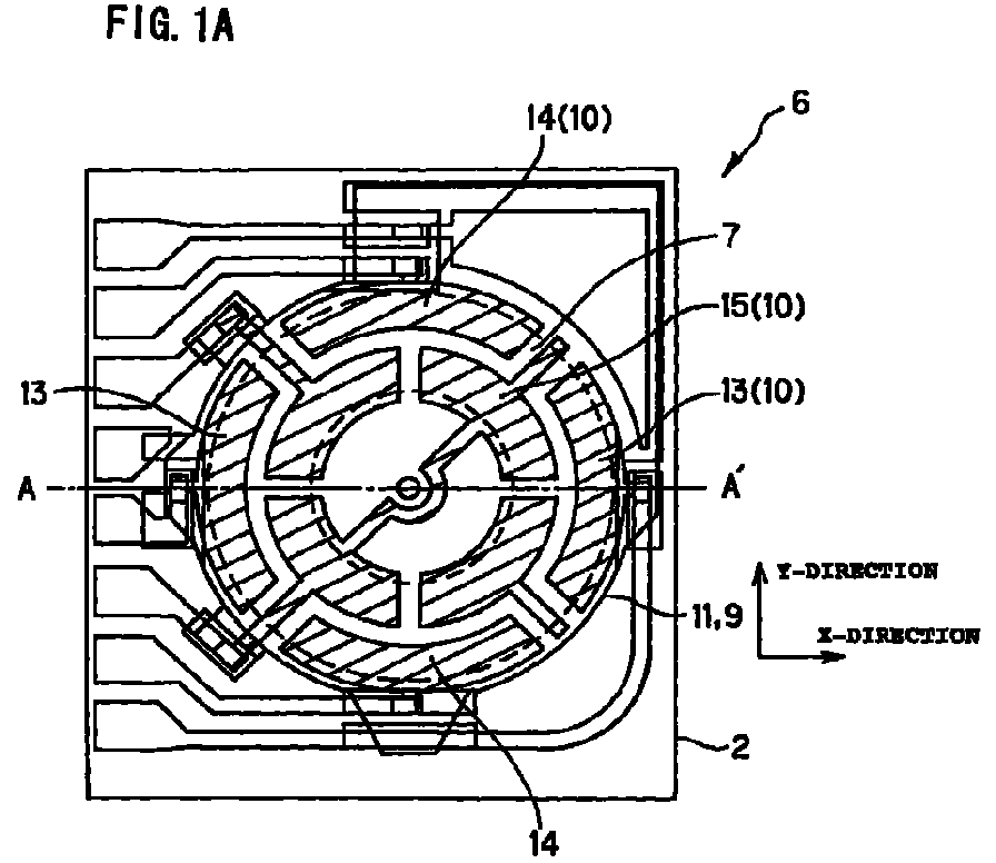
- the three-axis sensor had a basement 8 provided in a state in which a weight serving as a operating member 1 was placed by being suspended by a flexible substrate 3 put over a hollow portion 7. Further, the three-axis sensor had a piezoelectric material 11 placed on this basement 8 in such a manner as to be sandwiched between lower electrodes 9 and upper electrodes 10. Incidentally, the lower electrodes 9 and the piezoelectric material 11 were formed in such a manner as to cover the entire flexible substrate 3.
- a pair of elements for detecting an acceleration component in X-direction, a pair of elements for detecting an acceleration component in Y-direction, and a pair of elements for detecting an acceleration component in Z-direction were provided by forming a pair of electrodes 13 corresponding to X-direction, a pair of electrodes 14 corresponding to Y-direction, and a pair of electrodes 15 corresponding to Z-direction on this piezoelectric material 11.
- the electrodes of each of these pairs were separated from each other. Differently from this, the electrodes 15 of the pair corresponding to Z-direction were connected to each other.
- the upper electrodes 10 made of gold, the lower electrodes 9 made of platinum, the piezoelectric material 11 made of PZT, and circuit (pattern) and bonding pads made of silver were used.
- the trimming processing was performed on the element X2 so that the shape of the electrode 13b corresponding to the element X2 for X-direction was axially symmetric with respect to X-axis, and so that the difference between the absolute values of the excitation outputs of the elements of the pair corresponding to X-axis became small.
- the reason for making the shape axially symmetric with respect to X-axis was to reduce noises due of a component force in Y-direction in the elements of the pair corresponding to X-direction.
- the level of the trimming to be performed was determined according to preliminarily determined amounts of portions to be cut and of a decrease in sensitivity.
- the excitation output of all of the elements of the pair corresponding to X-direction when oscillated in Z-direction after the trimming processing was 0 mV.
- the noises to the elements of the pair corresponding to X-axis and to be caused corresponding to the axes other than X-axis were reduced.
- the trimming processing was performed by using a laser.
- the trimming processing was performed on the electrodes 15 corresponding to Z-direction of the three-axis sensor used in the first embodiment.
- noises to the elements of the pair corresponding to Z-direction and to be caused corresponding to the axes other than Z-axis were reduced.
- the capacitance of the elements of the pair corresponding to Z-direction before the trimming processing (see FIG. 4A) when oscillated in X-direction (30 mV corresponds to 10 ms -2 .) was 640 pF.
- the excitation output thereof was 6.7 mV. That is, a noise having a magnitude of 6.7 mV caused corresponding to the other axes by the excitation in X-direction was observed.
- the trimming processing was performed on the element so that the difference between the absolute values of the excitation outputs of the elements of the pair corresponding to Z-axis when oscillated in X-direction became small.
- the level of the trimming to be performed was determined, similarly as in the case of the first embodiment.
- which of the elements (one of which is indicated by "Z1" and the other of which is sometimes indicated by "Z2" hereunder) of the pair corresponding to Z-direction should undergo the trimming processing was determine as follows by the signs of electric charges generated in all of the elements of the pair corresponding to Z-direction and all of the elements of the pair corresponding to X-direction when oscillated in X-direction.
- the trimming processing was performed on the element Z1. Conversely, if the signs was different form each other, the trimming processing was performed on the element Z2. In the case of this embodiment, the signs of both the electric charges were opposite to each other. Thus, the trimming processing was performed on the electrode 15a (Z2).
- the excitation output of all of the elements of the pair corresponding to Z-direction when oscillated in X-direction after the trimming processing was 0 mV.
- the noises to the elements of the pair corresponding to Z-axis and to be caused corresponding to the axes other than Z-axis were reduced.
- the trimming processing was performed, similarly as in the first embodiment.
- a three-axis sensor is oscillated by using one of X-axis, Y-axis, and Z-axis as an excitation axis
- electric charges produced in the two piezoelectric elements placed at positions, which are symmetric with respect to a operating member are completely canceled.
- noises to the piezoelectric elements corresponding to the axes other than the excitation axis are suppressed. Consequently, the detecting precision of the sensor can be enhanced.
- the detecting precision corresponding to the excitation output in the direction of the primary axis is improved by decreasing noises caused by oscillating the sensor device in the direction corresponding to each of the other axes.
Abstract
The present invention provides a method for adjusting the
sensitivity of an acceleration detecting device comprising a pair of
piezoelectric elements, of an acceleration sensor device for detecting an
externally acting acceleration. According to this method, electric
charges produced in the pair of piezoelectric elements placed at
positions being symmetric with respect to a weight are made to be equal
to each other. The electric outputs of the piezoelectric elements are
changed by varying the electrostatic capacity of the acceleration sensor
device. Thus, what is called noise sensitivity is suppressed.
Description
- The present invention relates to a method for adjusting the sensitivity of an acceleration detecting device capable of detecting at least one of components, which respectively correspond to the directions of three orthogonal axes, namely, X-axis, Y-axis, and Z-axis, of an externally acting acceleration, which acts thereon.
- In the automobile and machine industries, there has been an increase in demand for sensors capable of accurately detecting physical quantities, such as force, acceleration, and magnetism. Especially, compact sensors capable of detecting each of two-dimensional or three-dimensional components of such physical quantities are demanded.
- For example, a sensor having a plurality of piezoelectric elements mounted on a flexible plate mounted on a flexible substrate having an operating member is disclosed in the Japanese Unexamined Patent Publication No. 5-26744.
- This sensor is configured so that the flexible substrate deforms according to a physical quantity externally acting on the operating member. The direction and magnitude of the externally acting physical quantity are detected by a single acceleration detecting device in a three-dimensional manner on the basis of electric charges that are produced in the piezoelectric elements according to strain due to the deformation of the flexible substrate. FIG. 8 is a perspective diagram illustrating the concept of a coordinate system for a three-axis sensor.
- This will be explained hereinbelow by taking an acceleration sensor device, which has an operating member as a weight, as an example of such a sensor device. In the case that an externally acting acceleration a is exerted on an acceleration detecting device as illustrated in FIGS. 2A and 2B, an inertial force f acts on a
weight 1 in a direction opposite to the direction of the acceleration a. This inertial force f causes the deformation of aflexible substrate 3 put on theweight 1 and supports 2. - Electric charges according to the direction and magnitude of strain due to the deformation and according to the direction and magnitude of polarization of
piezoelectric materials 5 put on theflexible substrate 3 are produced in thepiezoelectric materials 5. Thus, the detection of the direction and magnitude of the externally acting acceleration is enabled by outputting the electric charges fromupper electrodes lower electrode 21 as electric signals. - The aforementioned acceleration detecting device is configured so that components of the externally acting acceleration, which respectively correspond to the directions of X-axis, Y-axis, and Z-axis, are detected by a single acceleration detecting device as components. As a result, for example, even when the
weight 1 undergoes the influence of the acceleration only in the direction of Z-axis, as illustrated in FIG. 9B, the strain due to the deformation occurs not only in thepiezoelectric element 20x for detecting X-axis component of the acceleration, but in thepiezoelectric element 20y (not shown in FIG. 9B) for detecting Y-axis component of the acceleration. Consequently, electric charges are produced in thepiezoelectric elements - The
weight 1, however, does not undergo the influence of the acceleration only in the directions of X-axis and Y-axis, so that it is necessary to prevent electric outputs of the electric charges produced in thepiezoelectric elements - Thus, the aforementioned acceleration detecting device employs a method of electrically canceling the produced charges by configuring the pair of piezoelectric elements.
- As illustrated in FIGS. 2A and 2B, a piezoelectric device, which corresponds to each of X-axis, Y-axis, and Z-axis, of the acceleration detecting device comprises at least one pair of piezoelectric elements placed at positions that are symmetric with respect to the
weight 1. Because of the symmetric positions of the pair of piezoelectric elements with respect to theweight 1, the amounts of strain of (that is, the amounts of the electric charges respectively produced in) these piezoelectric elements of the pair are almost equal to each other. Furthermore, as shown in FIGS. 9A,9B and 9C,polarization processing having the same magnitude is performed on the piezoelectric elements so that, among piezoelectric materials constituting the piezoelectric elements of the pairs, the piezoelectric materials to be used for detecting X-axis component and Y-axis component of the acceleration have opposite polarities, and that the piezoelectric materials to be used for detecting Z-axis component of the acceleration have the same polarity. - When the
weight 1 is oscillated by such polarization processing in the direction of Z-axis as illustrated in FIG. 9B, the electric charges of opposite polarities produced in thepiezoelectric elements 20x for detecting X-axis component and those 20y (not shown) for detecting Y-axis component are canceled. Thus, no electric signals are outputted from these piezoelectric elements. On the other hand, when theweight 1 is oscillated in the directions of X-axis or Y-axis the as illustrated in FIG. 9C, the electric charges produced in thepiezoelectric elements 20z for detecting Z-axis component are canceled, so that no electric signals are outputted from theseelements 20z. - However, sometimes, the quantities of electric charges to be produced in the piezoelectric elements of the pair are not equal to each other owing to defective conditions at the time of forming the piezoelectric elements, for instance, variation in the electrode area of the piezoelectric elements, variation in the dielectric constant of the piezoelectric elements, a deviation of the position of the weight, and variation in deformation caused by the bending of the flexible substrate.
- In such a case, the electric charges produced in the piezoelectric elements of the pair are not completely canceled but outputted therefrom as electrical signals. Thus, for example, the sensitivity in the direction of X-axis is indicated despite the fact that the acceleration sensor device undergoes the influence of the acceleration only in the direction of Z-axis (hereunder, such sensitivity will be referred to as "another axis noise").
- It is necessary for ensuring the reliability of the sensor to limit a ratio of the another axis noise to the sensitivity in the direction of an axis to be detected (hereunder, such sensitivity will be referred to as "principal axis sensitivity") within a predetermined range (for instance, if the principal axis sensitivity is 100 %, the another axis noise should be equal to or less than 5 %). On the other hand, it is very difficult to limit the another axis noise within the predetermined range in the process of manufacturing the acceleration sensor devices. Thus, there is the necessity for a method for calibrating the another axis noise of the sensor device after manufactured.
- The present invention is accomplished in view of the aforementioned circumstances.
- Accordingly, the present invention provides a method for adjusting the sensitivity of an acceleration detecting device, according to which electrical outputs of piezoelectric elements of a pair of an acceleration detecting device are canceled by making the amounts of electric charges, which are respectively produced in a pair of piezoelectric elements placed at positions symmetric with respect to a weight, equal to each other, to thereby suppress the aforementioned another axis noise.
- According to the present invention there is provided a method for adjusting sensitivity of an acceleration sensor device having an acceleration detecting device consisting of a pair of piezoelectric elements for detecting an externally acting acceleration. This method includes the step of changing an electric output of at least one of the piezoelectric elements by changing electrostatic capacity of the acceleration sensor device. In the case of this method, the acceleration sensor device having an acceleration detecting device may comprises a weight, a support that is installed around said weight and has a hollow portion, a flexible substrate put on the support so that the weight is suspended in the hollow portion of said support, and a pair of piezoelectric elements.
- In the case of the method of the present invention, if the acceleration detecting device is adapted to detect an acceleration component in X-direction or Y-direction, the electrostatic capacity may be changed so that the difference between the absolute values of excitation outputs respectively generated in the piezoelectric elements of the acceleration detecting device becomes small when the acceleration sensor device is oscillated in Z-direction. If the acceleration detecting device is adapted to detect an acceleration component in Z-direction, the electrostatic capacity may be changed so that the difference between the absolute values of excitation outputs respectively generated in the piezoelectric elements of the acceleration detecting device becomes small when the acceleration sensor device is oscillated in X-direction or Y-direction.
- In the case of the method of the present invention, two pairs of the piezoelectric elements may be provided in said acceleration sensor device correspondingly to two orthogonal axes. In the case of the method of the present invention, three pairs of the piezoelectric elements may be provided in said acceleration sensor device correspondingly to three orthogonal axes.
- Further, in the case of the method of the present invention, if the acceleration detecting device consisting of the pair of piezoelectric elements is adapted to detect an acceleration component in X-direction, the electrostatic capacity may be changed so that the shapes of the piezoelectric elements are symmetric with respect to X-axis and so that the difference between the absolute values of excitation outputs respectively generated in the piezoelectric elements of the acceleration detecting device becomes small when the acceleration sensor device is oscillated in Z-direction. If the acceleration detecting device consisting of the pair of piezoelectric elements is adapted to detect an acceleration component in Y-direction, the electrostatic capacity may be changed so that the difference between the absolute values of excitation outputs respectively generated in the piezoelectric elements of the acceleration detecting device becomes small when the acceleration sensor device is oscillated in Z-direction.
- According to the present invention, which of electrodes respectively corresponding to the piezoelectric elements of the pair for detecting an acceleration component in Z-direction should undergo trimming processing, may be determined according to whether or not an excitation output generated in the piezoelectric elements for detecting an acceleration component in Z-direction and an excitation output generated in the piezoelectric elements for detecting an acceleration component in X-direction are different in sign from each other when the acceleration sensor device is oscillated in X-direction, and according to whether or not an excitation output generated in the piezoelectric elements for detecting an acceleration component in Z-direction and an excitation output generated in the piezoelectric elements for detecting an acceleration component in Y-direction are different in sign from each other when the acceleration sensor device is oscillated in Y-direction.
- Further, according to the present invention, an adjusting capacitance, which is connected to an electrode corresponding to each of the piezoelectric elements of the pair, may be formed at a portion, which corresponds to the support, of a piezoelectric material of a corresponding one of the piezoelectric elements of the pair. Furthermore, the trimming processing may be performed on the adjusting capacitance instead of performing the trimming processing on the electrode. In this case, preferably, the adjusting capacitance is connected to an electrode corresponding to the piezoelectric element, which has a larger excitation output, of the pair between the piezoelectric elements of the pair, whose excitation outputs are made to be different from each other.
- Furthermore, according to the present invention, a part of the electrode may be placed at a portion, which corresponds to said support or to a operating member, of a piezoelectric material corresponding to one of the piezoelectric element of the pair. Further, the trimming processing may be performed at the part of the electrode. In this case, preferably, an electrode corresponding to the piezoelectric element, which has a larger excitation output, of the pair between the pair of the piezoelectric elements, whose excitation outputs are made to be different from each other, has a part placed on a portion, which corresponds to the support or to the operating member, of the piezoelectric material. Moreover, the electrode may be formed like a comb and may have bottom land portions each formed on the portion, which corresponds to the support or to the operating member, of the piezoelectric material, and may have tooth-like portions each projected from corresponding one of the bottom land portions and each extended from a portion, which corresponds to the hollow portion, of the piezoelectric material. The bottom land portions each provided between adjacent ones of said tooth-like portions maybe cut by performing trimming processing.
- Furthermore, the trimming processing may be performed on a portion, which is provided at the side of the operating member or of the support, of the electrode along the circumference of a circle, the center of which is an origin (O). Alternatively, the trimming processing may be performed on the electrode along a line segment connecting an origin (O) to a point provided on the circumference of a circle, the center of which is the origin (O).
- Other features, objects and advantages of the present invention will become apparent from the following description of preferred embodiments with reference to the drawings in which like reference characters designate like or corresponding parts throughout several views, and in which:
- FIG. 1A is a plan diagram showing the general configuration of a three-axis sensor;
- FIG. 1B is a sectional diagram taken on line A-A' of FIG. 1A;
- FIG. 2A is a plan diagram illustrating an operation of the three-axis sensor;
- FIG. 2B is a longitudinally sectional diagram illustrating an operation of the three-axis sensor;
- FIG. 3A is a plan diagram illustrating the three-axis sensor before the trimming is performed thereon according to an embodiment of the method for adjusting the sensitivity of an acceleration sensor device of the present invention;
- FIG. 3B is a plan diagram illustrating the three-axis sensor after the trimming is performed thereon according to this embodiment of the method for adjusting the sensitivity of an acceleration sensor device of the present invention;
- FIG. 4A is a plan diagram illustrating the three-axis sensor before the trimming is performed thereon according to another embodiment of the method for adjusting the sensitivity of an acceleration sensor device of the present invention;
- FIG. 4B is a plan diagram illustrating the three-axis sensor after the trimming is performed thereon according to another embodiment of the method for adjusting the sensitivity of an acceleration sensor device of the present invention;
- FIGS. 5A, 5B, and 5C are plan views of a three-axis sensor, which illustrate the trimming processing according to another embodiment of the method for adjusting the sensitivity of an acceleration sensor device of the present invention;
- FIG. 6 is a plan view of a three-axis sensor, which illustrates the trimming processing according to another embodiment of the method for adjusting the sensitivity of an acceleration sensor device of the present invention;
- FIG. 7 is a plan view of a three-axis sensor, which illustrates the trimming processing according to another embodiment of the method for adjusting the sensitivity of an acceleration sensor device of the present invention;
- FIG. 8 is a perspective diagram illustrating the concept of a coordinate system for a three-axis sensor; and
- FIGS. 9A, 9B, and 9C are longitudinally sectional diagrams illustrating operations of a three-axis sensor.
-
- According to the present invention, the electric outputs of the piezoelectric elements are changed by varying the electrostatic capacity of the acceleration sensor device. Thus, noises to the acceleration sensor device are reduced. Incidentally, the term "piezoelectric element" is defined as a portion of the piezoelectric material, which is sandwiched between upper and lower electrodes in the upward or downward direction thereof. Practically, in the case of using a pair of electrodes separated from each other, the trimming processing is performed thereon so that the shapes of the electrodes of the pair are axially symmetric with respect to a same straight line passing through the center of the hollow portion. Furthermore, in the case that such electrodes compose a device for detecting an acceleration component in X-direction or Y-direction, the trimming processing is performed on thereon so that the difference between the absolute values of excitation or oscillation outputs respectively generated in the piezoelectric elements of the pair becomes small when the device is oscillated in Z-direction. On the other hand, in the case that such electrodes compose a device for detecting an acceleration component in Z-direction, the trimming processing is performed on thereon so that the difference between the absolute values of excitation or oscillation outputs respectively generated in the piezoelectric elements of the pair becomes small when the device is oscillated in X-direction or Y-direction. Further, in the case of employing a pair of electrodes that are connected to each other and that constitute a device for detecting an acceleration component in Z-direction, the trimming processing is performed on thereon so that the difference between the absolute values of excitation or oscillation outputs respectively generated in the piezoelectric elements of the pair becomes small when the device is oscillated in X-direction or Y-direction. Incidentally, it is desirable that the difference between the absolute values of excitation outputs is not more than 5 %.
- This will be explained hereinbelow by taking a three-axis sensor, which has devices each including a pair of electrodes separated from each other, corresponding to X-direction and Y-direction, and which has a device including a pair of electrodes connected to each other corresponding to Z-direction, as an example.
- In the case of such a three-axis sensor, the trimming processing is performed on the electrodes corresponding to X-direction so that the shape of the
electrodes 13 corresponding to X-direction is axially symmetric with respect to X-axis, as illustrated in FIG. 3B, and so that the difference between the absolute values of the excitation outputs generated respectively in the elements of the pair corresponding to X-direction becomes small when the device is oscillated in Z-direction. - Preferably, the elements corresponding to X-direction is adapted to detect only a component force in X-direction. Thus, it is necessary to reduce noises owing to the detection of component forces in Y-direction and Z-direction. Further, the purpose of making the shape of the pair of the
electrodes 13 corresponding to X-direction axially symmetric with respect to X-axis is to reduce noises due to the component force in Y-direction. That is, the direction of strain caused in the piezoelectric materials when oscillated in Y-direction varies with and has opposite signs respectively corresponding to the sides of X-axis. Conversely, the direction of polarization of one of theelectrodes 13 of the pair corresponding to X-direction is the same direction of polarization. Thus, the signs of the electric charges are determined by the direction of the deformation. Therefore, the electric charge generated in each of the electrodes of the pair can be approximately zero. Consequently, noises due to the component force in Y-direction can be decreased. - Further, the purpose of making the difference between the absolute values of the excitation outputs generated in the elements of the pair corresponding to X-direction small is to reduce noises caused owing to the component force in Z-direction in the elements corresponding to X-direction.
- The signs or polarities of the electric charges produced in the elements are determined by a product of the direction of polarization and the direction of deformation of the elements. Further, the directions of polarization of the elements of the pair corresponding to X-direction are opposite to each other. On the other hand, the excitation output of the elements is given by (Q/C) where Q denotes an amount of electric charge produced in each of the elements, and C designates the capacitance thereof. When oscillated in Z-direction, the deformations caused in the piezoelectric materials of the elements of the pair corresponding to X-direction have the same direction. As a result, the electric charges produced in the elements of the pair corresponding to X-direction have opposite sign or polarities. Therefore, the signs of the excitation outputs of the elements of the pair corresponding to X-direction are different from each other. Consequently, the excitation output of the entirety of the device corresponding to X-direction should be canceled. Namely, the device corresponding to X-direction should generate no excitation output. However, actually, there is a difference between the absolute values of the excitation outputs of the elements owing to the difference in the amount of produced electric charge between the elements of the pair corresponding to X-direction. This results in generation of noises corresponding to the other axes. That is, as described in TABLE 1 listed below, when the amount of electric charge produced in one 13a (hereunder sometimes indicated by "X1") of the elements of the pair corresponding to X-direction before the trimming is Q, the amount of electric charge produced in the
other element 13b (hereunder sometimes indicated by "X2") is -(Q + ΔQ). Further, the excitation output of the element X1 (13a) is Q/C1 where C1 designates the capacitance of the element X1. Furthermore, the excitation output of the element X2 (13b) isAcceleration-in-X-direction Detecting Device X1 X2 Total Polarization Direction + - Deformation Direction + + Produced Charge Q -(Q+ΔQ) -ΔQ Capacitance C1 C2+ΔC Excitation Output Q/C1 - Thus, in the case of the method of the present invention, as described in TABLE 2 listed below, the amount of electric charge generated in and the capacitance of the device corresponding to X-direction are adjusted by performing the trimming processing. Thus, the difference between the absolute values of the excitation outputs of the elements of the pair of the device corresponding to X-direction are made to be small. Consequently, when oscillated in Z-direction, the excitation output of the entire device corresponding to X-direction is 0. Further, the noises due to the component force in Z-direction is reduced. Because the electrodes of the pair corresponding to X-direction are separated from each other, the amount of electric charges generated in and the capacitance of the elements of the pair of the device corresponding to X-axis can be individually measured. Thus, the trimming processing is performed according to the measurement values thereof.
Acceleration-in-X-direction Detecting Device X1 X2 Total Polarization Direction + - Deformation Direction + + Produced Charge Q -Q 0 Capacitance C1 C2 C1+C2 Excitation Output Q/C1 -Q/C2 0 - Incidentally, when oscillated in X-direction, the directions of deformations respectively caused in the elements of the pair of the device corresponding to X-direction are opposite to each other. Moreover, as described above, the directions of polarization of such elements are opposite to each other. Thus, the electric charges respectively produced in such elements have the same sign or polarity, so that the excitation outputs of such elements are not canceled and can be measured.
- Further, according to the present invention, the trimming processing is performed on the electrodes corresponding to Y-direction so that the shape of the electrodes corresponding to Y-direction is axially symmetric with respect to Y-axis, and so that the difference between the absolute values of the excitation outputs generated respectively in the elements of the pair corresponding to Y-direction becomes small when the device is oscillated in Z-direction.
- Preferably, the elements corresponding to Y-direction is adapted to detect only a component force in Y-direction. Thus, it is necessary to reduce noises owing to the detection of component forces in X-direction and Z-direction. Further, the purpose of making the shape of the pair of the electrodes corresponding to Y-direction axially symmetric with respect to Y-axis is to reduce noises due to the component force in X-direction. Further, the purpose of making the difference between the absolute values of the excitation outputs generated in the elements of the pair corresponding to Y-direction small when oscillated in Z-direction is to reduce noises caused owing to the component force in Z-direction in the elements corresponding to Y-direction. For the same reason as in the case of the device corresponding to X-direction, the noises caused corresponding to the axes other than the excitation axis can be reduced. Because the electrodes of the pair corresponding to Y-direction are separated from each other, the amount of electric charges generated in and the capacitance of the elements of the pair of the device corresponding to Y-axis can be individually measured. Thus, the trimming processing is performed according to the measurement values thereof.
- Furthermore, according to the present invention, the trimming processing is performed on the electrodes corresponding to Z-direction so that the difference between the absolute values of the excitation outputs generated respectively in the elements of the pair corresponding to X-direction or Y-direction becomes small when the device is oscillated in X-direction or Y-direction. The purpose of this is to reduce noises produced owing to the component force in X-direction or Y-direction in the elements corresponding to Z-direction.
- The signs or polarities of the electric charges produced in the elements are determined, as described above, by a product of the direction of polarization and the direction of deformation of the elements. Further, the directions of polarization of the elements of the pair corresponding to Z-direction are the same one. When oscillated in X-direction or Y-direction, the directions of deformations caused in the piezoelectric materials of the elements of the pair corresponding to Z-direction are opposite to each other. As a result, the electric charges produced in the elements of the pair corresponding to Z-direction have opposite sign or polarities. Therefore, the signs of the excitation outputs of the elements of the pair corresponding to Z-direction should be canceled. That is, the device corresponding to Z-direction should generate no excitation output. However, actually, there is a difference between the absolute values of the excitation outputs of the elements owing to the difference in the amount of produced electric charge between the elements of the pair corresponding to Z-direction. This results in generation of noises corresponding to the other axes. Namely, as described in TABLE 3 listed below, for instance, when oscillated in X-direction, if the amount of electric charge produced in one 15b (hereunder sometimes indicated by "Z1") of the elements of the pair corresponding to Z-direction before the trimming is Q', the amount of electric charge produced in the
other element 15a (hereunder sometimes indicated by "Z2") is -(Q' + ΔQ). Further, the excitation output of the element Z1 (15b) is Q'/C3 where C3 designates the capacitance of the element Z1. Furthermore, the excitation output of the element Z2 (15a) isAcceleration-in-Z-direction Detecting Device Acceleration-in-X-direction Detecting Device Z1 Z2 Total X1 X2 Total Polarization Direction + + + - Deformation Direction + - + - Produced Charge Q' -(Q'+ΔQ) - ΔQ Q Q 2Q Capacitance C3 C4+ΔC C1 C2 C1+C2 Excitation Output Q'/C3 Q/C1 Q/ C2 - Hence, in the case of the method of the present invention, as described in TABLE 4 listed below, the amount of electric charge generated in and the capacitance of the device corresponding to Z-direction are adjusted by performing the trimming processing on the electrodes corresponding to Z-direction. Thus, the difference between the absolute values of the excitation outputs of the elements of the pair of the device corresponding to Z-direction are made to be small. Consequently, when oscillated in X-direction or Y-direction, the excitation output of the entire device corresponding to Z-direction is 0. Moreover, the noises due to the component force in X-direction or Y-direction is reduced.
Acceleration-in-Z-direction Detecting Device Z1 Z2 Total Polarization Direction + + Deformation Direction + - Produced Charge Q' -Q' 0 Capacitance C3 C4 C3+C4 Excitation Output Q'/C3 -Q'/C4 0 - Preferably, the trimming processing of the electrodes corresponding to Z-direction is performed on edge portions thereof in the vicinity of the
electrodes 13 corresponding to X-direction, as illustrated in FIG. 4B, when noises produced due to the component force in X-direction are reduced. The reason for this is as follows. That is, when oscillated in X-direction, deformation caused in the electrodes corresponding to Z-axis is large in the vicinity of X-axis, while deformation caused in these electrodes is small, namely, almost no deformation caused therein in the proximity of Y-axis. Therefore, the trimming processing performed in the edge portions thereof in the vicinity of theelectrodes 13 corresponding to X-direction has little influence on Y-axis. Moreover, the trimming thereof is achieved with high sensitivity. Furthermore, similarly, in the case of reducing noises caused owing to the component force in Y-direction, it is preferable to perform the trimming processing of the electrodes corresponding to Z-direction in the edge portions thereof in the vicinity of the electrodes corresponding to Y-direction. - Electrodes of the pair corresponding to Z-direction are connected to each other. Thus, the excitation outputs of the elements of the pair corresponding to Z-direction cannot be individually measured. It is determined in the following manner which of these elements undergoes the trimming processing. First, the amounts of electric charges respectively produced in the entire device corresponding to Z-direction and the entire device corresponding to X-direction when oscillated in X-direction are obtained. Then, the signs or polarities of the electric charges are compared with each other. If the electric charges have the same sign, the trimming processing is performed on the element Z1. Conversely, if the electric charges have opposite signs, the trimming processing is performed on the element Z2. That is, if ΔQ is positive,
- Incidentally, when oscillated in Z-direction, the directions of deformations respectively generated in the elements of the pair corresponding to Z-direction are the same one. Further, as described above, these elements are polarized in the same direction. Thus, the electric charges respectively produced in these elements have the same sign or polarity. Consequently, the excitation outputs of these elements can be measured.
- According to the present invention, the trimming processing may be performed on an adjusting capacitance or
capacitor 17 that is connected to theupper electrodes 10 and formed on a portion of the piezoelectric material, which corresponds to thesupport 2, as illustrated in FIG. 5A, without performing the trimming processing directly onto the electrodes. The trimming processing of the adjustingcapacitance 17 formed on thesupport 2 avoids difficulty in performing trimming processing on the electrodes formed on a thin flexible substrate by using a laser. - Furthermore, according to the present invention, as illustrated in FIG. 5C, the sensitivity of the sensor device may be adjusted by providing electrodes, to which parts can be soldered, in each of a group of the upper electrodes 22 and a group of the
lower electrodes 21 of larger excitationoutput piezoelectric element 20, then soldering chip capacitors 23 (namely, a X-direction trimming capacitor 23a, a Y-direction trimming capacitor 23b, and a Z-direction trimming capacitor) to such electrodes, and increasing the capacitance. - In this case, a difference is preliminarily provided between the excitation outputs of the piezoelectric elements of the pair. The adjusting
capacitance 17 is connected to the element, whose excitation output is larger than that of the other element when no trimming capacitors are provided. This is because of the facts that the excitation output decreases when the trimming capacitors producing no electric charge are added thereto, and that thus, the capacity of the trimming capacitors adjusts a decrease in the excitation output. Incidentally, in this case, the excitation output is a voltage, which is determined by a ratio (Q/C) of the produced electric charge Q to the capacitance C. For instance, in the case illustrated in FIG. 5A, the adjustingcapacitance 17 is connected to theelectrodes - Further, according to the present invention, as illustrated in FIG. 5B, the
upper electrodes 10 may have unusuallylarge projection parts 18 projected therefrom to parts, which correspond to and are placed on thesupport 2 and the operatingmember 1, of the piezoelectric materials. This avoids difficulty in performing trimming processing on the electrodes formed on a thin flexible substrate by using a laser. I this case, a difference is preliminarily provided between the excitation outputs of the piezoelectric elements of the pair. Preferably, one of these element, which provides a larger excitation output if no unusually large projection portion is provided therein, have a projection portion that is larger than an ordinary projection and that is disposed on a part, which corresponds to the support or the operating member, of the piezoelectric material. The excitation output decreases when the projection portions producing no electric charge are added thereto, while the excitation output increases when the area (or capacity) of the projection portions is decreased by the trimming processing. Thus, the size of each of the projection portions is adjusted so that a desired excitation output is obtained. Incidentally, in this case, the excitation output is a voltage, which is determined by a ratio (Q/C) of the produced electric charge Q to the capacitance C. Further, a large amount of electric charge is produced in the projection portion located in the very neighborhood of the flexible substrate. Therefore, to detect such electric charge, a projection portion is usually formed in the sensor. - For instance, in the case illustrated in FIG. 5B, the
electrodes - Furthermore, as illustrated in FIG. 6, each of the
upper electrodes 10 may be formed like a comb, and havebottom land portions 19, which are provided on parts of the piezoelectric material corresponding to thesupport 1 and the operatingmember 1, and tooth-like portions 20, which project from the bottom land portions and to a part corresponding to thehollow portion 7. Moreover, the bottom land portions each provided between adjacent tooth-like portions may be cut by the trimming processing. This avoids difficulty in performing trimming processing on the electrodes formed on a thin flexible substrate by using a laser. Furthermore, this has an advantage in that efficient adjustment is achieved by employing a width of one tooth-like portion as a minimum unit for adjustment. Additionally, this has another advantage in that the sensor itself can be compact, as compared with the case of providing the adjusting capacitance. - On the other hand, the method of employing the electrodes of the shape as illustrated in FIG. 7 has an advantage in that fine adjustment is achieved, as compared with the case of forming the electrode like a comb. It is determined according to the use of the three-axis sensor which kind of the electrodes should be selected.
- There are two techniques for performing the trimming processing, namely, one is to cut a portion, which are located at the side of the operating
member 1 or thesupport 2, of theupper electrode 10 along the circumference of a circle, the center of which is an origin (O), as illustrated in FIG. 7. The other is to cut the electrode along a line segment drawn from the origin (O) in the circle to a point on the circumference thereof. - In a first case of cutting a portion, which are located at the side of the
support 2, of theupper electrode 10 along the circumference of a circle, the center of which is an origin (O), the excitation output largely varies with the area of the cut portion. As a result, the trimming processing is achieved with high sensitivity. Therefore, this is suitable for the case of adjusting the excitation output within a large range. On the other hand, in a second case of cutting a portion, which is located at the side of the operatingmember 1, of theupper electrode 10 along the circumference of a circle, the center of which is an origin (O), the excitation output slightly varies with the area of the cut portion. Thus, the trimming processing is achieved with low sensitivity. Therefore, this is suitable for the case of performing fine adjustment of the excitation output. The sensitivity in the case of cutting the electrode along a line segment drawn from the origin (O) in the circle to a point on the circumference thereof has an intermediate level between the levels of the sensitivity in the first and second cases. - According to the methods of the present invention, when the device is oscillated by using one of X-axis, Y-axis, and Z-axis as an excitation axis, electric charges respectively produced in two piezoelectric elements, which are placed at the positions symmetric with respect to the operating member, among the piezoelectric elements corresponding the axes other than the excitation axis, can be completely canceled. Thus, noises caused correspondingly to the axes other than the excitation axis are suppressed. Consequently, the detecting precision of the sensor can be enhanced.
- Further, the trimming processing is usually performed by using a laser. However, it is necessary for performing the trimming processing with good precision to accurately perform the positioning of parts. This operation is very hard to achieve. When the trimming processing is performed according to the method of the present invention on a three-axis sensor having piezoelectric elements formed in the same place, it is sufficient to perform the positioning only once. Thus, the working efficiency can be enhanced.
- Incidentally, the method for adjusting the sensitivity of a sensor device can be applied to a single-axis sensor. However, in the case of a single-axis sensor having the constitution obtained by extracting only one axis from the three-axis sensor, for instance, in the case of a single-axis sensor having only elements for detecting an acceleration component in X-axis, if the excitation outputs corresponding to Y-direction and Z-direction are detected, it cannot be achieved that only the excitation output corresponding to X-direction is measured with good precision.
- Hereinafter, the present invention will be described in detail still more by referring to the embodiments shown in the accompanying drawings. The present invention is, however, not limited thereto.
- First, noises corresponding to axes other than the excitation axis were reduced by performing the trimming processing on electrodes corresponding to X-direction in a three-axis sensor. As shown in FIG. 1, the three-axis sensor had a
basement 8 provided in a state in which a weight serving as a operatingmember 1 was placed by being suspended by aflexible substrate 3 put over ahollow portion 7. Further, the three-axis sensor had apiezoelectric material 11 placed on thisbasement 8 in such a manner as to be sandwiched betweenlower electrodes 9 andupper electrodes 10. Incidentally, thelower electrodes 9 and thepiezoelectric material 11 were formed in such a manner as to cover the entireflexible substrate 3. A pair of elements for detecting an acceleration component in X-direction, a pair of elements for detecting an acceleration component in Y-direction, and a pair of elements for detecting an acceleration component in Z-direction were provided by forming a pair ofelectrodes 13 corresponding to X-direction, a pair ofelectrodes 14 corresponding to Y-direction, and a pair ofelectrodes 15 corresponding to Z-direction on thispiezoelectric material 11. Incidentally, regarding the pair of theelectrodes 13 corresponding to X-direction and the pair of theelectrodes 14 corresponding to Y-direction, the electrodes of each of these pairs were separated from each other. Differently from this, theelectrodes 15 of the pair corresponding to Z-direction were connected to each other. Further, in the case of the three-axis of this embodiment, theupper electrodes 10 made of gold, thelower electrodes 9 made of platinum, thepiezoelectric material 11 made of PZT, and circuit (pattern) and bonding pads made of silver were used. - The capacitance of one (hereunder sometimes indicated by "X1") of the elements of the pair corresponding to X-direction before the trimming processing (see FIG. 3A) when oscillated in Z-direction (30 mV corresponds to 10 ms-2.) was 279 pF. The excitation output thereof was 120 mV. Further, when oscillated in Z-direction, the capacitance of the other (hereunder sometimes indicated by "X2) of the elements of the pair corresponding to X-direction was 286 pF. The excitation output thereof was 131 mV. Thus, the total capacitance of all of the elements of the pair corresponding to X-direction was 565 pF. The excitation output thereof was 7.5 mV. That is, a noise having a magnitude of 7.5 mV, which was caused corresponding to the other axes by the excitation in Z-direction, was observed.
- In the aforementioned three-axis sensor, the trimming processing was performed on the element X2 so that the shape of the
electrode 13b corresponding to the element X2 for X-direction was axially symmetric with respect to X-axis, and so that the difference between the absolute values of the excitation outputs of the elements of the pair corresponding to X-axis became small. The reason for making the shape axially symmetric with respect to X-axis was to reduce noises due of a component force in Y-direction in the elements of the pair corresponding to X-direction. The level of the trimming to be performed was determined according to preliminarily determined amounts of portions to be cut and of a decrease in sensitivity. - The excitation output of all of the elements of the pair corresponding to X-direction when oscillated in Z-direction after the trimming processing was 0 mV. Thus, the noises to the elements of the pair corresponding to X-axis and to be caused corresponding to the axes other than X-axis were reduced.
- Incidentally, in this embodiment, the trimming processing was performed by using a laser.
- The trimming processing was performed on the
electrodes 15 corresponding to Z-direction of the three-axis sensor used in the first embodiment. Thus, noises to the elements of the pair corresponding to Z-direction and to be caused corresponding to the axes other than Z-axis were reduced. - The capacitance of the elements of the pair corresponding to Z-direction before the trimming processing (see FIG. 4A) when oscillated in X-direction (30 mV corresponds to 10 ms-2.) was 640 pF. The excitation output thereof was 6.7 mV. That is, a noise having a magnitude of 6.7 mV caused corresponding to the other axes by the excitation in X-direction was observed.
- In the aforementioned three-axis sensor, the trimming processing was performed on the element so that the difference between the absolute values of the excitation outputs of the elements of the pair corresponding to Z-axis when oscillated in X-direction became small. The level of the trimming to be performed was determined, similarly as in the case of the first embodiment. Moreover, which of the elements (one of which is indicated by "Z1" and the other of which is sometimes indicated by "Z2" hereunder) of the pair corresponding to Z-direction should undergo the trimming processing was determine as follows by the signs of electric charges generated in all of the elements of the pair corresponding to Z-direction and all of the elements of the pair corresponding to X-direction when oscillated in X-direction. Namely, if the signs of both of the electric charges were the same, the trimming processing was performed on the element Z1. Conversely, if the signs was different form each other, the trimming processing was performed on the element Z2. In the case of this embodiment, the signs of both the electric charges were opposite to each other. Thus, the trimming processing was performed on the
electrode 15a (Z2). - The excitation output of all of the elements of the pair corresponding to Z-direction when oscillated in X-direction after the trimming processing was 0 mV. Thus, the noises to the elements of the pair corresponding to Z-axis and to be caused corresponding to the axes other than Z-axis were reduced.
- Incidentally, in this embodiment, the trimming processing was performed, similarly as in the first embodiment.
- According to the present invention, in the case that a three-axis sensor is oscillated by using one of X-axis, Y-axis, and Z-axis as an excitation axis, among the piezoelectric elements corresponding to the axes other than the excitation axis, electric charges produced in the two piezoelectric elements placed at positions, which are symmetric with respect to a operating member, are completely canceled. Thus, noises to the piezoelectric elements corresponding to the axes other than the excitation axis are suppressed. Consequently, the detecting precision of the sensor can be enhanced. Further, in the case of applying the method of the present invention to a single-axis sensor, the detecting precision corresponding to the excitation output in the direction of the primary axis is improved by decreasing noises caused by oscillating the sensor device in the direction corresponding to each of the other axes.
- Although the preferred embodiments of the present invention have been described above, it should be understood that the present invention is not limited thereto and that other modifications will be apparent to those skilled in the art without departing from the spirit of the invention.
Claims (14)
- A method for adjusting sensitivity of an acceleration sensor device having an acceleration detecting device consisting of a pair of piezoelectric elements for detecting an externally acting acceleration, said method including the step of:changing an electric output of said piezoelectric elements by changing electrostatic capacity of said acceleration sensor device.
- The method for adjusting sensitivity of an acceleration sensor device according to claim 1, wherein said acceleration sensor device having an acceleration detecting device that comprises:a weight;a support, installed around said weight, having a hollow portion;a flexible substrate put on said support so that said weight is suspended in said hollow portion of said support; anda pair of piezoelectric elements.
- The method for adjusting sensitivity of an acceleration sensor device according to claim 1 or 2, wherein, in a case that said acceleration detecting device is adapted to detect an acceleration component in X-direction or Y-direction, the electrostatic capacity is changed so that a difference between absolute values of excitation outputs respectively generated in said piezoelectric elements of said acceleration detecting device become small when said acceleration sensor device is oscillated in Z-direction, and wherein, in a case that said acceleration detecting device is adapted to detect an acceleration component in Z-direction, the electrostatic capacity is changed so that a difference between absolute values of excitation outputs respectively generated in said piezoelectric elements of said acceleration detecting device becomes small when said acceleration sensor device is oscillated in X-direction or Y-direction.
- The method for adjusting sensitivity of an acceleration sensor device according to claim 1, 2 or 3, wherein two pairs of said piezoelectric elements are provided in said acceleration sensor device correspondingly to two orthogonal axes.
- The method for adjusting sensitivity of an acceleration sensor device according to one of claims 1 to 4, wherein three pairs of said piezoelectric elements are provided in said acceleration sensor device correspondingly to three orthogonal axes.
- The method for adjusting sensitivity of an acceleration sensor device according to one of claims 1 to 5, wherein, in a case that said acceleration detecting device consisting of said pair of piezoelectric elements is adapted to detect an acceleration component in X-direction, the electrostatic capacity is changed so that shapes of said piezoelectric elements are symmetric with respect to X-axis and so that a difference between absolute values of excitation outputs respectively generated in said piezoelectric elements of said acceleration detecting device becomes small when said acceleration sensor device is oscillated in Z-direction, and wherein, in a case that said acceleration detecting device consisting of said pair of piezoelectric elements is adapted to detect an acceleration component in Y-direction, the electrostatic capacity is changed so that shapes of said piezoelectric elements are symmetric with respect to Y-axis and so that a difference between absolute values of excitation outputs respectively generated in said piezoelectric elements of said acceleration detecting device becomes small when said acceleration sensor device is oscillated in Z-direction.
- The method for adjusting sensitivity of an acceleration sensor device according to one of claims 1 to 6, which further comprises the step of determining which of electrodes respectively corresponding to said piezoelectric elements of the pair for detecting an acceleration component in Z-direction should undergo trimming processing, according to whether or not an excitation output generated in said piezoelectric elements for detecting an acceleration component in Z-direction and an excitation output generated in said piezoelectric elements for detecting an acceleration component in X-direction are different in sign from each other when said acceleration sensor device is oscillated in X-direction, and according to whether or not an excitation output generated in said piezoelectric elements for detecting an acceleration component in Z-direction and an excitation output generated in said piezoelectric elements for detecting an acceleration component in Y-direction are different in sign from each other when said acceleration sensor device is oscillated in Y-direction.
- The method for adjusting sensitivity of an acceleration sensor device according to one of claims 1 to 7, which further comprises the steps of forming an adjusting capacitance, which is connected to an electrode corresponding to each of said piezoelectric elements of the pair, at a portion, which corresponds to said support, of an piezoelectric material of a corresponding one of said piezoelectric elements of the pair, and then performing trimming processing on said adjusting capacitance instead of performing trimming processing on said electrode.
- The method for adjusting sensitivity of an acceleration sensor device according to claim 8, wherein said adjusting capacitance is connected to an electrode corresponding to said piezoelectric element, which has a larger excitation output, of the pair between said piezoelectric elements of the pair, whose excitation outputs are made to be different from each other.
- The method for adjusting sensitivity of an acceleration sensor device according to one of claims 1 to 7, wherein a part of said electrode is placed at a portion, which corresponds to said support or to a operating member, of a piezoelectric material corresponding to said piezoelectric element of the pair, and wherein trimming processing is performed at the part of said electrode.
- The method for adjusting sensitivity of an acceleration sensor device according to claim 10, wherein an electrode corresponding to said piezoelectric element, which has a larger excitation output, of the pair between the pair of said piezoelectric elements, whose excitation outputs are made to be different from each other, has a part placed on a portion, which corresponds to said support or to said operating member, of said piezoelectric material.
- The method for adjusting sensitivity of an acceleration sensor device according to claim 10 or 11, wherein said electrode is formed like a comb and has bottom land portions each formed on said portion, which corresponds to said support or to said operating member, of said piezoelectric material, and has tooth-like portions each projected from corresponding one of said bottom land portions and each extended from a portion, which corresponds to said hollow portion, of said piezoelectric material, and wherein said bottom land portions each provided between adjacent ones of said tooth-like portions are cut by performing trimming processing.
- The method for adjusting sensitivity of an acceleration sensor device according to one of claims 1 to 7, 10, 11 or 12, which further comprises the step of performing trimming processing on a portion, which is provided at the side of said operating member or of said support, of said electrode along a circumference of a circle, the center of which is an origin (O).
- The method for adjusting sensitivity of an acceleration sensor device according to one of claims 1 to 7, 10, 11 or 12, which further comprises the step of performing trimming processing on said electrode along a line segment connecting an origin (O) to a point provided on a circumference of a circle, the center of which is the origin (O).
Applications Claiming Priority (4)
| Application Number | Priority Date | Filing Date | Title |
|---|---|---|---|
| JP8489499 | 1999-03-26 | ||
| JP8489499 | 1999-03-26 | ||
| JP2000073022 | 2000-03-15 | ||
| JP2000073022A JP2000346865A (en) | 1999-03-26 | 2000-03-15 | Sensitivity adjusting method for acceleration sensor element |
Publications (1)
| Publication Number | Publication Date |
|---|---|
| EP1039303A1 true EP1039303A1 (en) | 2000-09-27 |
Family
ID=26425865
Family Applications (1)
| Application Number | Title | Priority Date | Filing Date |
|---|---|---|---|
| EP00302353A Withdrawn EP1039303A1 (en) | 1999-03-26 | 2000-03-22 | Method for adjusting sensitivity of acceleration sensor |
Country Status (3)
| Country | Link |
|---|---|
| US (1) | US6474134B1 (en) |
| EP (1) | EP1039303A1 (en) |
| JP (1) | JP2000346865A (en) |
Cited By (1)
| Publication number | Priority date | Publication date | Assignee | Title |
|---|---|---|---|---|
| WO2021074024A1 (en) * | 2019-10-14 | 2021-04-22 | Kistler Holding Ag | Acceleration sensor |
Families Citing this family (6)
| Publication number | Priority date | Publication date | Assignee | Title |
|---|---|---|---|---|
| US20040020292A1 (en) * | 2002-04-17 | 2004-02-05 | Deng Ken Kan | Single chip piezoelectric triaxial MEMS accelerometer |
| JP2008194729A (en) * | 2007-02-13 | 2008-08-28 | Fujitsu Ltd | Manufacturing method, laser beam machining method and laser beam machining apparatus for small device |
| DE102008040525B4 (en) * | 2008-07-18 | 2017-05-24 | Robert Bosch Gmbh | Micromechanical sensor element |
| US11693021B2 (en) * | 2020-06-09 | 2023-07-04 | Infineon Technologies Ag | Combined corrugated piezoelectric microphone and corrugated piezoelectric vibration sensor |
| US11611835B2 (en) | 2020-06-09 | 2023-03-21 | Infineon Technologies Ag | Combined corrugated piezoelectric microphone and corrugated piezoelectric vibration sensor |
| US11691871B2 (en) | 2021-06-18 | 2023-07-04 | Infineon Technologies Ag | Microelectromechanical system (MEMS) vibration sensor having a segmented backplate |
Citations (4)
| Publication number | Priority date | Publication date | Assignee | Title |
|---|---|---|---|---|
| JPS62250309A (en) * | 1986-04-23 | 1987-10-31 | Matsushita Electric Ind Co Ltd | Manufacture of angular velocity sensor |
| EP0459939A1 (en) * | 1990-05-30 | 1991-12-04 | Copal Company Limited | Capacitive acceleration sensor with free diaphragm |
| EP0731357A1 (en) * | 1994-09-28 | 1996-09-11 | Wacoh Corporation | Acceleration sensor using piezoelectric element |
| US5639973A (en) * | 1990-10-12 | 1997-06-17 | Okada; Kazuhiro | Force detector |
Family Cites Families (17)
| Publication number | Priority date | Publication date | Assignee | Title |
|---|---|---|---|---|
| DE3371417D1 (en) * | 1983-02-21 | 1987-06-11 | Vibro Meter Ag | Dual accelerometer, method of manufacturing it and its application |
| US4455500A (en) * | 1983-07-28 | 1984-06-19 | Western Geophysical Company Of America | Sensitivity and capacitance adjustment method for piezoelectric accelerometers |
| US5506454A (en) * | 1991-03-20 | 1996-04-09 | Hitachi, Ltd. | System and method for diagnosing characteristics of acceleration sensor |
| JP3141954B2 (en) | 1991-07-17 | 2001-03-07 | 株式会社ワコー | Force / acceleration / magnetism sensors using piezoelectric elements |
| JPH0526894A (en) * | 1991-07-19 | 1993-02-02 | Mitsubishi Petrochem Co Ltd | Acceleration sensor with self-diagnostic circuit |
| JPH0526890A (en) * | 1991-07-19 | 1993-02-02 | Mitsubishi Petrochem Co Ltd | Acceleration sensor with self-diagnostic circuit |
| DE69211269T2 (en) * | 1991-09-24 | 1997-01-23 | Murata Manufacturing Co | Accelerometer |
| DE4132414A1 (en) * | 1991-09-28 | 1993-04-08 | Deutsche Aerospace | Acceleration sensor with integrated sensitivity monitoring - contains piezoelectric element in one or more main axes, and operation is testable by stimulating flexural beam electrically or mechanically |
| DE4135369A1 (en) * | 1991-10-26 | 1993-05-13 | Bosch Gmbh Robert | Bipolar piezoelectric accelerometer with built-in test facility - has upper and lower electrodes in halves for application of test voltage and measurement of deformation |
| GB2266588B (en) * | 1992-04-24 | 1995-11-15 | British Aerospace | Vibrating rate sensor tuning |
| JPH085654A (en) * | 1994-06-23 | 1996-01-12 | Murata Mfg Co Ltd | Acceleration sensor |
| KR0139506B1 (en) * | 1994-10-07 | 1998-07-15 | 전성원 | Self-diagnostic accelerometer with symmetric proof-mass and its preparation method |
| JPH08201425A (en) * | 1995-01-30 | 1996-08-09 | Mitsubishi Electric Corp | Semiconductor acceleration detector |
| JP3036679B2 (en) * | 1995-07-07 | 2000-04-24 | 住友精密工業株式会社 | Correction method of other axis interference output of acceleration sensor |
| DE69627603T2 (en) * | 1995-10-09 | 2003-12-18 | Matsushita Electric Ind Co Ltd | Accelerometer and manufacturing method therefor, and shock detector using such a sensor |
| US5763983A (en) * | 1997-01-12 | 1998-06-09 | Motorola Inc. | Single crystal piezoelectric transformer using extensional vibration modes and method for driving the same |
| US6050144A (en) * | 1997-06-04 | 2000-04-18 | Matsushita Electric Industrial Co., Ltd. | Acceleration sensor |
-
2000
- 2000-03-15 JP JP2000073022A patent/JP2000346865A/en not_active Withdrawn
- 2000-03-20 US US09/528,557 patent/US6474134B1/en not_active Expired - Fee Related
- 2000-03-22 EP EP00302353A patent/EP1039303A1/en not_active Withdrawn
Patent Citations (4)
| Publication number | Priority date | Publication date | Assignee | Title |
|---|---|---|---|---|
| JPS62250309A (en) * | 1986-04-23 | 1987-10-31 | Matsushita Electric Ind Co Ltd | Manufacture of angular velocity sensor |
| EP0459939A1 (en) * | 1990-05-30 | 1991-12-04 | Copal Company Limited | Capacitive acceleration sensor with free diaphragm |
| US5639973A (en) * | 1990-10-12 | 1997-06-17 | Okada; Kazuhiro | Force detector |
| EP0731357A1 (en) * | 1994-09-28 | 1996-09-11 | Wacoh Corporation | Acceleration sensor using piezoelectric element |
Non-Patent Citations (1)
| Title |
|---|
| PATENT ABSTRACTS OF JAPAN vol. 012, no. 125 (P - 691) 19 April 1988 (1988-04-19) * |
Cited By (1)
| Publication number | Priority date | Publication date | Assignee | Title |
|---|---|---|---|---|
| WO2021074024A1 (en) * | 2019-10-14 | 2021-04-22 | Kistler Holding Ag | Acceleration sensor |
Also Published As
| Publication number | Publication date |
|---|---|
| US6474134B1 (en) | 2002-11-05 |
| JP2000346865A (en) | 2000-12-15 |
Similar Documents
| Publication | Publication Date | Title |
|---|---|---|
| US6928872B2 (en) | Integrated gyroscope of semiconductor material with at least one sensitive axis in the sensor plane | |
| US5691471A (en) | Acceleration and angular velocity detector | |
| US5166571A (en) | Vibration gyro having an H-shaped vibrator | |
| EP1891450B1 (en) | Method of manufacturing a capacitive acceleration sensor, and a capacitive acceleration sensor | |
| US8096181B2 (en) | Inertial sensor | |
| JP3457037B2 (en) | Integrated accelerometer | |
| JP3941694B2 (en) | Acceleration sensor | |
| US6430998B2 (en) | Resonant element | |
| US8833163B2 (en) | Angular velocity sensor | |
| US8115367B2 (en) | Piezoelectric actuator provided with a displacement meter, piezoelectric element, and positioning device | |
| CN105190319B (en) | Acceleration transducer and its manufacture method | |
| JPH06331646A (en) | Semiconductor acceleration sensor | |
| EP1039303A1 (en) | Method for adjusting sensitivity of acceleration sensor | |
| CN107990885B (en) | Gyro sensor, method for manufacturing gyro sensor, electronic device, and moving object | |
| JP4561820B2 (en) | Angular velocity sensor | |
| US6435000B1 (en) | Method for calibrating sensitivity of acceleration sensor | |
| US5877421A (en) | Acceleration sensor | |
| JP3043477B2 (en) | Sensor using change in capacitance | |
| CN110514189B (en) | Gyroscope and method for fusing and correcting quadrature error of gyroscope | |
| JP2007101203A (en) | Angular velocity sensor | |
| JP2002071708A (en) | Semiconductor dynamic quantity sensor | |
| JPH0627133A (en) | Three dimensional acceleration sensor | |
| JP2000028634A (en) | Capacitive physical quantity detector | |
| JP2585639Y2 (en) | Acceleration sensor using piezoelectric element | |
| JPH06258340A (en) | Multi-dimensional acceleration detector |
Legal Events
| Date | Code | Title | Description |
|---|---|---|---|
| PUAI | Public reference made under article 153(3) epc to a published international application that has entered the european phase |
Free format text: ORIGINAL CODE: 0009012 |
|
| AK | Designated contracting states |
Kind code of ref document: A1 Designated state(s): DE FR GB |
|
| AX | Request for extension of the european patent |
Free format text: AL;LT;LV;MK;RO;SI |
|
| 17P | Request for examination filed |
Effective date: 20010109 |
|
| AKX | Designation fees paid |
Free format text: DE FR GB |
|
| STAA | Information on the status of an ep patent application or granted ep patent |
Free format text: STATUS: THE APPLICATION HAS BEEN WITHDRAWN |
|
| 18W | Application withdrawn |
Effective date: 20030221 |