EP1038546A1 - Multi-directional steerable catheters and control handles - Google Patents
Multi-directional steerable catheters and control handles Download PDFInfo
- Publication number
- EP1038546A1 EP1038546A1 EP00302299A EP00302299A EP1038546A1 EP 1038546 A1 EP1038546 A1 EP 1038546A1 EP 00302299 A EP00302299 A EP 00302299A EP 00302299 A EP00302299 A EP 00302299A EP 1038546 A1 EP1038546 A1 EP 1038546A1
- Authority
- EP
- European Patent Office
- Prior art keywords
- proximal
- distal
- puller wire
- piston
- section
- Prior art date
- Legal status (The legal status is an assumption and is not a legal conclusion. Google has not performed a legal analysis and makes no representation as to the accuracy of the status listed.)
- Granted
Links
Images


Classifications
-
- A—HUMAN NECESSITIES
- A61—MEDICAL OR VETERINARY SCIENCE; HYGIENE
- A61M—DEVICES FOR INTRODUCING MEDIA INTO, OR ONTO, THE BODY; DEVICES FOR TRANSDUCING BODY MEDIA OR FOR TAKING MEDIA FROM THE BODY; DEVICES FOR PRODUCING OR ENDING SLEEP OR STUPOR
- A61M25/00—Catheters; Hollow probes
- A61M25/01—Introducing, guiding, advancing, emplacing or holding catheters
- A61M25/0105—Steering means as part of the catheter or advancing means; Markers for positioning
- A61M25/0133—Tip steering devices
- A61M25/0147—Tip steering devices with movable mechanical means, e.g. pull wires
-
- A—HUMAN NECESSITIES
- A61—MEDICAL OR VETERINARY SCIENCE; HYGIENE
- A61M—DEVICES FOR INTRODUCING MEDIA INTO, OR ONTO, THE BODY; DEVICES FOR TRANSDUCING BODY MEDIA OR FOR TAKING MEDIA FROM THE BODY; DEVICES FOR PRODUCING OR ENDING SLEEP OR STUPOR
- A61M25/00—Catheters; Hollow probes
- A61M25/01—Introducing, guiding, advancing, emplacing or holding catheters
- A61M25/0105—Steering means as part of the catheter or advancing means; Markers for positioning
- A61M25/0133—Tip steering devices
- A61M25/0136—Handles therefor
-
- A—HUMAN NECESSITIES
- A61—MEDICAL OR VETERINARY SCIENCE; HYGIENE
- A61M—DEVICES FOR INTRODUCING MEDIA INTO, OR ONTO, THE BODY; DEVICES FOR TRANSDUCING BODY MEDIA OR FOR TAKING MEDIA FROM THE BODY; DEVICES FOR PRODUCING OR ENDING SLEEP OR STUPOR
- A61M25/00—Catheters; Hollow probes
- A61M25/01—Introducing, guiding, advancing, emplacing or holding catheters
- A61M25/0105—Steering means as part of the catheter or advancing means; Markers for positioning
- A61M25/0133—Tip steering devices
- A61M25/0147—Tip steering devices with movable mechanical means, e.g. pull wires
- A61M2025/015—Details of the distal fixation of the movable mechanical means
Definitions
- the present invention is directed to multidirectional steerable catheters and to multidirectional control handles for use with the multidirectional steerable catheters.
- Electrode catheters have been in common use in medical practice for many years. They are used to stimulate and map electrical activity in the heart and to ablate sites of aberrant electrical activity.
- the electrode catheter In use, the electrode catheter is inserted into a major vein or artery, e.g., femoral artery, and then guided into the chamber of the heart which is of concern. Within the heart, the ability to control the exact position and orientation of the catheter tip is critical and largely determines how useful the catheter is.
- a major vein or artery e.g., femoral artery
- U.S. Patent No. RE 34,502 describes a catheter having a control handle comprising a housing having a piston chamber at its distal end.
- a piston is mounted in the piston chamber and is afforded lengthwise movement.
- the proximal end of the elongated catheter body is attached to the piston.
- a puller wire is attached to the housing and extends through the piston, through the catheter body, and into a tip section at the distal end of the catheter body.
- the distal end of the puller wire is anchored in the tip section of the catheter.
- the design described in RE 34,502 is generally limited to a catheter having a single puller wire. If a bidirectional catheter is desired, i.e., a catheter that can be deflected to form two different curves (e.g., deflect in more than one direction), more than one puller wire becomes necessary. When two puller wires are used, however, it is undesirable for both wires to be moved simultaneously.
- the handle design disclosed in RE 34,502 is not suitable for a two puller wire system. Accordingly, a need exists for a control handle capable of independently moving each of two puller wires but preventing simultaneous movement of the puller wires.
- the present invention is directed to steerable catheters and novel control handles for use therewith.
- the catheter comprises a catheter body, a tip section and a control handle.
- the catheter body has a tubular wall, proximal and distal ends, and at least one lumen extending therethrough.
- the tip section comprises a flexible tubing having proximal and distal ends and at least one lumen extending therethrough. The proximal end of the tip section is fixedly attached to the distal end of the catheter body.
- the control handle has proximal and distal ends and is mounted at its distal end to the proximal end of the catheter body.
- the control handle comprises a housing and a piston assembly.
- the housing has proximal and distal ends and a piston chamber extending therethrough, the piston chamber having proximal and distal ends.
- the piston assembly has proximal and distal portions and is slidably mounted in the piston chamber of the housing and longitudinally movable between proximal and distal positions.
- the distal portion of the piston assembly is fixedly attached to the proximal end of the catheter body.
- the proximal portion of the piston assembly comprises a distal section, a proximal section and a circumferential recess between the proximal section and distal section.
- the distal section has proximal and distal ends and comprises a plurality of notches at its proximal end.
- the proximal section comprises a plurality of longitudinal grooves about its entire circumference
- the piston assembly further comprises a ring having proximal and distal ends rotatably mounted on the piston assembly.
- the ring comprises a plurality of projections that extend radially inwardly into the circumferential recess and that are capable of being received by the longitudinal grooves.
- the number of projections is less than the number of longitudinal grooves.
- the ring further comprises a plurality of teeth at its distal end capable of being received by the notches.
- First and second puller wire anchors are slidably disposed within a corresponding longitudinal groove.
- First and second puller wires having proximal and distal ends extend from the control handle, through a lumen in the catheter body and into a lumen in the tip section. The proximal end of each puller wire is fixedly attached to a separate puller wire anchor in the control handle.
- First means is provided for causing deflection of the tip section to form a first curve in response to proximal movement of the first puller wire relative to the catheter body.
- Second means is provided for causing deflection of the tip section to form a second curve different from the first curve in response to proximal movement of the second puller wire relative to the catheter body.
- the deflecting means comprise off-axis lumens through which the puller wires extends and anchors that anchor the puller wires to the sides or distal end of the tip section or means for anchoring the puller wires to a tip electrode mounted at the distal end of the tip section.
- Another deflecting means is described in U.S. Patent Nos. 5,336,182 and 5,364,351, the disclosures of which are incorporated herein by reference.
- Distal movement of the piston relative to the handle housing results in a projection on the ring extending in one of the longitudinal grooves to thereby prevent longitudinal movement of the puller wire anchor in the groove relative to the handle housing.
- This causes deflection of the tip section in the direction of the lumen into which the puller wire connected to that anchor extends.
- Proximal movement of the piston relative to the handle housing causes rotation of the ring, thereby aligning that same projection with a different longitudinal groove to thereby prevent longitudinal movement of the puller wire anchor in the groove relative to the handle housing.
- This movement causes deflection of the tip section in the direction of the lumen into which the puller wire connected to that anchor extends.
- the catheter comprises an elongated catheter body 12 having proximal and distal ends, a tip section 14 at the distal end of the catheter body, and a control handle 16 at the proximal end of the catheter body.
- the catheter body 12 comprises an elongated tubular construction having a single, axial or central lumen 18 .
- the catheter body 12 can have additional lumens if desired, although a single central lumen 18 is presently preferred.
- the catheter body is flexible, i.e., bendable, but substantially non-compressible along its length.
- the catheter body 12 can be of any suitable construction and made of any suitable material.
- a presently preferred construction comprises an outer wall 20 made of polyurethane or PEBAXTM.
- the outer wall 20 comprises an imbedded braided mesh of stainless steel or the like to increase torsional stiffness of the catheter body 12 so that, when the control handle 16 is rotated, the tip section 14 will rotate in a corresponding manner.
- the outer diameter of the catheter body 12 is not critical, but is preferably no more than about 8 french, more preferably about 7 french.
- the thickness of the outer wall 20 is not critical, but is thin enough so that the central lumen 18 can accommodate at least two puller wires and one or more electrode lead wires.
- the inner surface of the outer wall 20 is lined with a stiffening tube 22 , which can be made of any suitable material, such as polyimide or nylon.
- the stiffening tube 22 along with the braided outer wall 20 , provides improved torsional stability while at the same time minimizing the wall thickness of the catheter, thus maximizing the diameter of the central lumen 18 .
- the outer diameter of the stiffening tube 22 is about the same as or slightly smaller than the inner diameter of the outer wall 20 .
- the tip section 14 comprises a short section of tubing 24 having an axial lumen 26 and first and second off-axis lumens 28 and 30 .
- the tubing 24 is made of a suitable non-toxic material that is preferably more flexible than the catheter body 12 .
- a presently preferred material for the tubing 24 is braided polyurethane, i.e., polyurethane with an embedded mesh of braided stainless steel or the like.
- the outer diameter of the tip section 14 like that of the catheter body 12 , is preferably no greater than about 8 french, more preferably about 7 french.
- the tip section 14 can have only two lumens, both off-axis lumens. A description of such a design is provided in U.S. Patent Application No. 09/205,631, entitled "Bidirectional Electrode Catheter", the disclosure of which is incorporated herein by reference.
- FIG. 2 A preferred means for attaching the catheter body 12 to the tip section 14 is illustrated in FIG. 2.
- the proximal end of the tip section 14 comprises an outer circumferential notch 32 that receives the inner surface of the outer wall 20 of the catheter body 12 .
- the tip section 14 and catheter body 12 are attached by glue or the like.
- the stiffening tube 22 is inserted into the catheter body.
- the distal end of the stiffening tube 22 is fixedly attached near the distal end of the catheter body 12 by forming a glue joint (not shown) with polyurethane glue or the like.
- a small distance e.g., about 3 mm, is provided between the distal end of the catheter body 12 and the distal end of the stiffening tube 22 to permit room for the catheter body 12 to receive the notch 32 of the tip section 14 .
- a force is applied to the proximal end of the stiffening tube 22 , and, when the stiffening tube is under compression, a first glue joint (not shown) is made between the stiffening tube 22 and the outer wall 20 by a fast drying glue joint e.g., Super GlueTM. Thereafter a second glue joint (not shown) is formed between the proximal ends of the stiffening tube 22 and outer wall 20 using a slower drying but stronger glue, e.g., polyurethane.
- a fast drying glue joint e.g., Super GlueTM
- a spacer 23 can be located within the catheter body between the distal end of the stiffening tube and the proximal end of the tip section.
- the spacer 23 provides a transition in flexibility at the junction of the catheter body and tip section, which allows this junction to bend smoothly without folding or kinking.
- a catheter having such a spacer is described in U.S. Patent Application No. 08/924,616/US-A-5 964 757, entitled “Steerable Direct Myocardial Revascularization Catheter", the disclosure of which is incorporated herein by reference.
- a tip electrode 38 At the distal end of the tip section 14 is a tip electrode 38 .
- the tip electrode 38 has a diameter about the same as the outer diameter of the tubing 24 .
- the tip electrode 38 is attached to the tubing 24 by creating a notch 40 in the proximal end of the tip electrode, placing the proximal end of the tip electrode on the distal end of the tubing, and filling the notch with glue.
- each ring electrode 42 is mounted on the tubing 24 proximal to the tip electrode 38 .
- Each ring electrode 42 is slid over the tubing 24 and fixed in place by glue or the like. It is understood that the presence, number and position of ring electrodes may vary as desired. Similarly, a tip electrode may be excluded if desired.
- the tip electrode 38 and ring electrodes 42 Can be made of any suitable material, and are preferably machined from platinum-iridium bar (90% platinum/10% iridium).
- the tip electrode 38 and ring electrodes 42 are each connected to a separate electrode lead wire 44 .
- the lead wires 44 extend through the axial lumen 26 of the tip section 14 , the central lumen 18 of the catheter body 12 , and the control handle 16 , and terminate at their proximal end in an input jack (not shown) that may be plugged into an appropriate monitor (not shown).
- an input jack not shown
- the portion of the lead wires 44 extending through the central lumen 18 of the catheter body 12 , control handle 16 and proximal end of the tip section 14 can be enclosed within a protective sheath (not shown), which can be made of any suitable material, preferably polyimide.
- the !ead wires 44 are attached to the tip electrode 38 and ring electrodes 42 by any suitable conventional technique. Connection of a lead wire 44 to the tip electrode 38 is accomplished, for example, by welding the lead wire 44 into a hole 46 in the tip electrode.
- Connection of a lead wire 44 to a ring electrode 42 is preferably accomplished by first making a small hole through the tubing 24 .
- a hole can be created, for example, by inserting a needle through the tubing 24 and heating the needle sufficiently to form a permanent hole (not shown).
- a lead wire 44 is then drawn through the hole by using a microhook or the like.
- the ends of the lead wires 44 are then stripped of any coating and soldered or welded to the underside of the ring electrode 42 , which is then slid into position over the hole and fixed in place with polyurethane glue or the like.
- Two puller wires 50 extend through the catheter body 12 .
- the puller wires 50 are anchored at their proximal ends to the control handle 16 and at their distal ends to the tip section 14 .
- the puller wires 50 are made of any suitable metal, such as stainless steel or Nitinol, and are preferably coated with TeflonTM or the like. The coating imparts lubricity to the puller wires 50 .
- the puller wires 50 preferably each have a diameter ranging from about 0.006 inch to about 0.010 inch.
- Two compression coils 52 are provided in the catheter body 12 , each in surrounding relation to a corresponding puller wire 50 .
- the compression coils 52 extend from the proximal end of the catheter body 12 to the proximal end of the tip section 14 .
- the compression coils 52 are made of any suitable metal, preferably stainless steel.
- the compression coils 52 are tightly wound on themselves to provide flexibility, i.e., bending, but to resist compression.
- the inner diameter of each compression coil 52 is preferably slightly larger than the diameter of the corresponding puller wire 50 .
- the TeflonTM coating on the puller wires 50 allows them to slide freely within the compression coils 52 .
- the outer surface of each compression coil 52 is covered by a flexible, non-conductive sheath 53 , e.g., made of polyimide tubing, to prevent contact between the compression coils 52 and the lead wires 44 .
- Each compression coil 52 is anchored at its proximal end to the proximal end of the stiffening tube 22 in the catheter body 12 by glue joint 54 and at its distal end to the tip settion 14 by glue joint 56 .
- Both glue joints 54 and 56 preferably comprise polyurethane glue or the like.
- the glue may be applied through a hole (not shown) made between the outer surface of the catheter body 12 and the central lumen 18 . Such a hole may be formed, for example, by a needle or the like that punctures the outer wall 20 of the catheter body 12 and the stiffening tube 22 , which is heated sufficiently to form a permanent hole.
- the glue is then introduced through the hole to the outer surface of the compression coil 52 and wicks around the outer circumference to form a glue joint about the entire circumference of the compress coil.
- a short section of plastic tubing 45 is provided around the lead wires 44 near the glue joint 54 to provide the lead wires with flexibility within the glue joint Alternatively, the distal ends of the compression coils 52 can be anchored in the distal end of the catheter body 12 .
- the puller wires 50 extend into the first off-axis lumen 28 and second off-axis lumen 30 of the tip section 14 .
- Each puller wire 50 extends through a plastic, preferably TeflonTM, sheath 55 , which prevents that puller wire from cutting into the wall of the tip section 14 when the tip section is deflected.
- Each puller wire 50 is anchored at its distal end to the tip electrode 38 within a blind hole 58 .
- the puller wires 50 are anchored in opposite sides of the tip electrode 38 so that the tip section can deflect in two opposing directions, as described in more detail below.
- a preferred method for anchoring each puller wire 50 in the tip electrode 38 is by crimping metal tubing (not shown) to the distal end of each puller wire 50 and soldering the metal tubing inside the blind hole 58 .
- Other means known to those skilled in the art for anchoring the puller wires 50 in the tip electrode 38 could also be used.
- one or both of the puller wires 50 can be anchored to the sides of the tip section 14 .
- the distal ends of the puller wires 50 comprise T-bar anchors 61 as described above and are preferably anchored by glue 62 in notches 63 in the side wall of the flexible tubing 24 as shown in FIG. 4 and as described in U.S. Patent Application Nos. 09/134,009 (entitled “Bi-Directional Steerable Catheter") and 09/099,796 (entitled “Multi-Element Tip Electrode Mapping Catheter”), the disclosures of which are incorporated herein by reference.
- the puller wires 50 can both be anchored to the same side of the tip section with one puller wire anchored proximal the other puller wire.
- the tip section could form a U-shaped curve.
- Other puller wire anchoring arrangements could also be provided to permit the tip section to deflect to form two different curves.
- the control handle 16 illustrated in FIGs. 5 to 7, comprises a handle housing 64 and a piston 66 , both having proximal and distal ends.
- this piston 66 moves both longitudinally and rotatably with respect to the handle housing 64 .
- the housing 64 and piston 66 preferably both comprise a rigid plastic, such as Delrin®, an acetal homopolymer commercially available from DuPont.
- the proximal end of the piston 66 is slidably and rotatably mounted within a piston chamber in the distal end of the handle housing 64 .
- the distal end of the piston 66 is fixedly attached to the proximal end of the catheter body 12 .
- the piston 66 has a thumb control 68 at its distal end.
- the handle housing 64 comprises a proximal section 130 and a distal section 132 .
- the distal end of the proximal section 130 of the housing 64 comprises a circumferential notch 134 into which the proximal end of the distal section 132 fits.
- the proximal section 130 and the distal section 132 can be press-fit together.
- the handle housing 64 can be formed of a single piece of plastic instead of proximal and distal sections.
- a grip piece 136 made of rubber or the like to provide comfort to the user.
- the piston has first and second longitudinal grooves 70 and 72 , each of the grooves having a proximal and distal end.
- the distal ends of the longitudinal grooves 70 and 72 are connected by a circumferential groove 74 .
- the longitudinal grooves 70 and 72 are deeper than the circumferential groove 74 , creating a step 78 at the distal ends of the longitudinal grooves under the circumferential groove.
- a puller wire anchor 76 is slidably mounted within each longitudinal groove 70 and 72 .
- the two puller wire anchors 76 each comprise a short metal rod, preferably made of aluminum or stainless steel.
- the step 78 at the distal ends of the longitudinal grooves 70 and 72 prevents the puller wire anchors 76 from sliding into the circumferential groove 74 .
- each puller wire 50 is fixedly attached to a corresponding puller wire anchor 76 by any suitable means, for example, by soldering the puller wire into a hole in the metal rod.
- the rod can have a small hole at its distal end and a larger hole at its proximal end.
- a piece of hypodermic stock or the like is crimped on the proximal end of the puller wire. The hypodermic stock fits into the larger hole in the rod, but not the smaller hole, preventing the puller wire from being pulled distally out of the rod.
- An internal passage 77 extends within the piston 66 through which the puller wires 50 and lead wires (not shown) extend.
- Two generally diagonally small holes 80 are provided in the step 78 , each in general alignment with one of the longitudinal grooves 70 and 72 and in communication with the internal passage 77 .
- the puller wires 50 extend through the holes 80 for connection to the puller wire anchors 76 .
- a set screw 82 extends radially inwardly from the handle housing 64 into the circumferential groove 74 .
- the piston can be rotated between first and second positions relative to the housing. Rotation of the piston 66 relative to the housing 64 results in movement of the circumferential groove 74 relative to the set screw 82 .
- the set screw 82 is aligned with the first longitudinal groove 70 , as shown in FIG. 7.
- the set screw 82 is aligned with the second longitudinal groove 72 .
- the set screw 82 could be replaced by a pin, ring or the like (for example, as described below) that is held stationary relative to the piston 66 , whether or not fixedly attached to the handle housing 64 .
- Distal movement of the piston 66 relative to the handle housing 64 results in longitudinal movement of the piston relative to the stationary set screw 82 .
- the set screw 82 is in its first position (i.e., aligned with the first longitudinal groove 70 ) and the piston 66 is moved distally relative to the handle housing 64 , the first longitudinal groove 70 (along with the piston) slides distally relative to the set screw, which extends radially inwardly into the first longitudinal groove.
- distal movement of the puller wire anchor 76a in the first longitudinal groove 70 is blocked by the stationary set screw 82 .
- the puller wire 50 connected to the blocked puller wire anchor 76a is also held stationary relative to the distally moving piston 66 and catheter body 12 , which is fixedly attached to the piston. This results in deflection of the tip section 14 in the direction of the off-axis lumen 28 or 30 into which that puller wire 50 extends.
- the set screw 82 blocks movement of the puller wire anchor 76b , which remains stationary relative to the distally-moving piston.
- the puller wire 50 connected to the puller wire anchor 76b is held stationary relative to the distally moving piston 66 and catheter body 12 , thus deflecting the tip section 14 in the direction of the off-axis lumen 28 or 30 into which that puller wire extends.
- This design permits deflection of the tip section 14 to form two different curves, and preferably to deflect in two different directions, while preventing simultaneous movement of the puller wires 50 .
- the above-described design could be used with a unidirectional catheter, i.e., having only a single puller wire. If only a single puller wire is included in the catheter, only a single longitudinal groove is provided in the piston. A circumferential groove is not necessary, but the set screw (or other pin) must extend into the longitudinal groove distal the puller wire anchor.
- FIGs. 8 to 13 An alternative embodiment of the inventive control handle 16 is shown in FIGs. 8 to 13.
- the handle 16 comprises a handle housing 64 and a piston assembly 65 , both having proximal and distal ends.
- the piston assembly 65 comprises a piston 66 at its proximal end and a thumb control 68 at its distal end, as well as additional components described in more detail below.
- the proximal end of the piston assembly 65 is slidably mourned within a piston chamber in the distal end of the handle housing 64 .
- the distal end of the piston assembly 65 is fixedly attached to the proximal end of the catheter body 12 .
- the piston 66 comprises an internal passage 77 extending therethrough through which the puller wires 50 and lead wires (not shown) extend.
- the handle housing 64 comprises a proximal section 130 and a distal section 132 .
- the distal end of the proximal section 130 of the housing 64 comprises a circumferential notch 134 into which the proximal end of the distal section 132 fits.
- the proximal section 130 and the distal section 132 can be press-fit together.
- a grip piece 136 made of rubber or the like to provide comfort to the user.
- the piston chamber has a first inner diameter 138 , a second inner diameter 140 , and a third inner diameter 142 .
- the first inner diameter 138 is proximal the second inner diameter 140 , both of which are distal the third inner diameter 142 .
- the second inner diameter 140 is smaller than the first inner diameter 138 , but is only slightly larger than the outer diameter of the piston 66 .
- the third inner diameter 142 is smaller than the first inner diameter 138 and preferably similar in size to the second inner diameter 140 .
- FIG. 11 shows the proximal portion of the piston assembly 65 , which comprises a proximal section 84 , a distal section 86 , and a circumferential recess 85 between the proximal section and distal section.
- the proximal section 84 comprises a series of longitudinal grooves, including deep longitudinal grooves 88 and shallow longitudinal grooves 90 , about its entire circumference.
- the depicted embodiment has two deep longitudinal grooves 88 and four shallow longitudinal grooves 90 , as shown best in FIG. 13.
- the two deep longitudinal grooves 88 are adjacent to each other.
- the longitudinal grooves 88 and 90 are separated from one another by dividing walls 92 .
- Each dividing wall 92 has an angled distal end 94 .
- a puller wire anchor 76 is slidably disposed within each deep longitudinal groove 88 .
- the distal ends of the deep longitudinal grooves 88 terminate in a vertical wall 79 .
- Each vertical wall 79 contains a small hole (not shown).
- Two puller wires 50 extend through the internal passage 77 and through one of the small holes so that the puller wires can be attached to the puller wire anchors 76 as described above.
- the distal section 86 which has proximal and distal ends, is spaced apart from the proximal section 84 by the circumferential recess 85 .
- the proximal end of the distal section 86 comprises a plurality of tooth-shaped notches 96 .
- the number of tooth-shaped notches 96 is the same as the number of dividing walls 92 , which in the depicted embodiment is six.
- the piston assembly 65 further comprises a ring 98 rotatably mounted on the piston 66 .
- the ring 98 is preferably made of a generally rigid plastic, such as Delrin®, acrylonitrilebutadiene-styrene resin, polyester, polyethylene or the like.
- the ring 98 has a proximal end 104 and a distal end 106 .
- the outer diameter of the ring 98 is slightly greater than the outer diameter of the distal portion of the piston 66 .
- the inner diameter of the ring 98 is slightly greater than the outer diameter of the circumferential recess 85 .
- the ring 98 has a plurality of projections 110 that extend radially inwardly into the circumferential recess 85 and that are sized to be received by the longitudinal grooves 88 and 90 .
- FIG. 12 depicts the ring 98 slid proximally so that it is positioned over the longitudinal grooves 88 and 90 with the projections 110 extending inwardly into the grooves.
- the projections 110 are spaced apart so that they can be aligned with every other longitudinal groove 88 and 90 .
- three projections 110 are provided on the ring 98 .
- the distal end 106 of the ring 98 comprises a plurality of teeth 108 spaced apart to be aligned with every other notch 96 . Accordingly, the number of teeth 108 is equal to half the number of notches 96 . In the depicted embodiment the ring 98 contains three teeth 108 .
- the teeth 108 have a thickness so they project inward, preferably to about the same depth as the projections 110 .
- the piston assembly 65 further comprises a cylindrical sleeve 114 disposed about the distal section 86 of the piston 66 .
- the sleeve 114 which has proximal and distal ends, is preferably made of a generally rigid plastic, such as Delrin®, polycarbonate or the like.
- the proximal end of the sleeve 114 contains three tooth-shaped notches 116 round its circumference that generally correspond in size, shape and position to the three teeth 108 on the distal end 106 of the ring 98 .
- the proximal end of the sleeve 114 fits against the top or outer portion of the ring 98 , and the projections 110 on the ring fit against the notches 96 on the proximal end of the distal section 86 of the piston. If the number of teeth 108 on the ring 98 is increased or decreased, the number of tooth-shaped notches 116 on the sleeve 114 is correspondingly increased or decreased.
- the ring 98 and sleeve 114 rotate together about the piston 66 due to the interlocking between the tooth-shaped notches 116 on the sleeve and the teeth 108 on the ring.
- the piston 66 comprises a circumferential groove 57 into which an o-ring (not shown) fits to seal the space between the piston and the sleeve.
- the ring 98 and sleeve 114 have approximately the same outer diameter, which is smaller than the first inner diameter 138 of the piston chamber but larger than the second and third diameters 140 and 142 of the piston chamber. Due to the difference between the first inner diameter 138 and the second inner diameter 140 , the handle housing 64 comprises a distal cylindrical flange 139 at the distal end of the piston chamber to prevent distal movement of the sleeve 114 (and thus the ring 98 ) relative to the housing, which also prevents distal movement of the sleeve out of the piston chamber.
- the handle housing 64 comprises a proximal cylindrical flange 141 midway trough the piston chamber to prevent proximal movement of the ring 98 (and thus the sleeve 114 ) relative to the housing.
- Movement of the piston 66 distally relative to the handle housing 64 e.g., by pushing on the thumb rest 68 , results in the piston sliding distally relative to the sleeve 114 and ring 98 so that the ring is positioned over the longitudinal grooves 88 and 90 rather than the circumferential recess 85 , as shown in FIG. 12.
- the projections 110 on the ring 98 are received by every other of the longitudinal grooves 88 and 90 . In the arrangement described, one projection 110 will be received by one of the deep longitudinal grooves 88 , but not the other.
- the projection 110 extending into the deep longitudinal groove 88 engages and blocks the puller wire anchor 76 in that groove, holding it and its associated puller wire 50 stationary relative to the distally-moving piston 66 .
- Such movement results in deflection of the tip section 14 in the direction of the off-axis lumen into which the distal end of the puller wire 50 extends.
- the ring 98 can be engaged by the handle housing 64 in any other manner such that the distal or proximal movement of the piston 66 relative to the housing causes the ring to remain longitudinally stationary relative to the distally or proximally moving piston, but still rotatable on the piston.
- the projections 110 To engage the puller wire anchor 76b in the adjacent deep longitudinal groove 88 , and thus enable deflection of the tip section in the direction of the off-axis lumen of the other puller wire 50 , the projections 110 must be moved into alignment with the adjacent longitudinal grooves. To accomplish this, the piston 66 is moved proximally relative to the handle housing 64 until the teeth 108 on the ring 98 engage the tooth shaped notches 96 on the proximal end of the distal section of the piston 86 . Because of the shapes of the teeth 108 and the notches 96 , the ring 98 rotates as the teeth 108 engage the notches 96 . The amount of rotation results in the projections 110 on the ring 98 being aligned with the adjacent longitudinal grooves 88 .
- the projections 110 are received by the adjacent longitudinal grooves 88 and 90 .
- the projection 110 received by the deep longitudinal groove 88 engages and blocks distal movement of the puller wire anchor 76b in that groove, holding it stationary relative to the distally-moving piston 66 in a manner similar to that described above.
- This also holds the puller wire 50 anchored to that puller wire anchor 76b stationary relative to the distally-moving piston 66 and catheter body 12 , resulting in deflection of the tip section 14 in the direction of the off-axis lumen into which that puller wire extends.
- the piston 66 When it is desired to again deflect the tip section 14 in the direction of the puller wire 50 in the first deep longitudinal groove 88 , the piston 66 is again moved proximally until the teeth 108 on the ring 98 engage the tooth shaped notches 96 . The ring 98 again rotates relative to the piston 66 as the teeth 108 of the ring engage the notches 96 . A different projection 110 then comes into alignment with the first deep longitudinal groove 88 .
- an identification mechanism is provided so that the physician can readily ascertain which puller wire 50 is engaged.
- a preferred mechanism comprises three holes 118 spaced 120° apart around the circumference of the sleeve 114 near its distal end, as shown in FIG. 10.
- the sleeve 114 is a different color than the piston 66 .
- the distal section 132 of the handle housing 64 has a hole 120 generally positioned in line with the holes 118 so that one of the holes 118 can be aligned with the hole 120 .
- the sleeve 114 rotates relative to the piston 66 and housing 64 , it is positioned in one of six positions relative to the piston and housing.
- one of the holes 118 is aligned with the hole 120 so that the user can see the piston 66 through the hole 120 .
- These three positions correspond to one of the puller wires being blocked.
- the user sees the sleeve 114 through the hole 120 .
- a set screw (not shown) can be provided to assure that the piston 66 is not separated from the handle housing 64 .
- the set screw could extend through the handle housing 64 and into one of the shallow longitudinal grooves 90 of the piston 66 .
- Other means for assuring that the piston is not separated from the handle housing can also be used.
- the ring 98 and sleeve 114 could be replaced with a single piece that performs all of the functions of the ring and sleeve described above.
- the sleeve 114 could be removed altogether. With such a design, the length of the distal section 130 of the handle housing 64 having the first inner diameter 138 would be decreased so that the second inner diameter 140 is much closer to the ring 98 .
- the above-described handle designs can be used with a multidirectional catheter having more than two puller wires.
- the number of longitudinal grooves (and puller wire anchors) would be increased to correspond to the number of puller wires.
- the number of deep longitudinal grooves (and puller wire anchors) would be increased to correspond to the number of puller wires.
- the number of protrusions on the ring would be modified so that only one protrusion extends into one of the deep longitudinal grooves.
- the protrusions on the ring would be aligned with every third longitudinal groove.
- the piston would be modified to have four deep longitudinal grooves and four shallow longitudinal grooves, and the protrusions on the ring would be aligned with every fourth longitudinal groove.
- the deep longitudinal grooves need not be adjacent each other.
- all of the longitudinal grooves can be of the same depth, similar to the deep longitudinal grooves.
- the ring can contain more or less teeth as desired, but preferably a number equal to the number of protrusions on the ring for simplicity in manufacturing the ring.
Abstract
Description
- The present invention is directed to multidirectional steerable catheters and to multidirectional control handles for use with the multidirectional steerable catheters.
- Electrode catheters have been in common use in medical practice for many years. They are used to stimulate and map electrical activity in the heart and to ablate sites of aberrant electrical activity.
- In use, the electrode catheter is inserted into a major vein or artery, e.g., femoral artery, and then guided into the chamber of the heart which is of concern. Within the heart, the ability to control the exact position and orientation of the catheter tip is critical and largely determines how useful the catheter is.
- Steerable catheters are generally well-known. For example, U.S. Patent No. RE 34,502 describes a catheter having a control handle comprising a housing having a piston chamber at its distal end. A piston is mounted in the piston chamber and is afforded lengthwise movement. The proximal end of the elongated catheter body is attached to the piston. A puller wire is attached to the housing and extends through the piston, through the catheter body, and into a tip section at the distal end of the catheter body. The distal end of the puller wire is anchored in the tip section of the catheter. In this arrangement, lengthwise movement of the piston relative to the housing results in deflection of the catheter tip section.
- The design described in RE 34,502 is generally limited to a catheter having a single puller wire. If a bidirectional catheter is desired, i.e., a catheter that can be deflected to form two different curves (e.g., deflect in more than one direction), more than one puller wire becomes necessary. When two puller wires are used, however, it is undesirable for both wires to be moved simultaneously. The handle design disclosed in RE 34,502 is not suitable for a two puller wire system. Accordingly, a need exists for a control handle capable of independently moving each of two puller wires but preventing simultaneous movement of the puller wires.
- The present invention is directed to steerable catheters and novel control handles for use therewith. The catheter comprises a catheter body, a tip section and a control handle. The catheter body has a tubular wall, proximal and distal ends, and at least one lumen extending therethrough. The tip section comprises a flexible tubing having proximal and distal ends and at least one lumen extending therethrough. The proximal end of the tip section is fixedly attached to the distal end of the catheter body.
- The control handle has proximal and distal ends and is mounted at its distal end to the proximal end of the catheter body. The control handle comprises a housing and a piston assembly. The housing has proximal and distal ends and a piston chamber extending therethrough, the piston chamber having proximal and distal ends. The piston assembly has proximal and distal portions and is slidably mounted in the piston chamber of the housing and longitudinally movable between proximal and distal positions. The distal portion of the piston assembly is fixedly attached to the proximal end of the catheter body. The proximal portion of the piston assembly comprises a distal section, a proximal section and a circumferential recess between the proximal section and distal section. The distal section has proximal and distal ends and comprises a plurality of notches at its proximal end. The proximal section comprises a plurality of longitudinal grooves about its entire circumference separated by dividing walls having angled distal ends.
- The piston assembly further comprises a ring having proximal and distal ends rotatably mounted on the piston assembly. The ring comprises a plurality of projections that extend radially inwardly into the circumferential recess and that are capable of being received by the longitudinal grooves. The number of projections is less than the number of longitudinal grooves. The ring further comprises a plurality of teeth at its distal end capable of being received by the notches.
- First and second puller wire anchors are slidably disposed within a corresponding longitudinal groove. First and second puller wires having proximal and distal ends extend from the control handle, through a lumen in the catheter body and into a lumen in the tip section. The proximal end of each puller wire is fixedly attached to a separate puller wire anchor in the control handle.
- First means is provided for causing deflection of the tip section to form a first curve in response to proximal movement of the first puller wire relative to the catheter body. Second means is provided for causing deflection of the tip section to form a second curve different from the first curve in response to proximal movement of the second puller wire relative to the catheter body. In one embodiment, the deflecting means comprise off-axis lumens through which the puller wires extends and anchors that anchor the puller wires to the sides or distal end of the tip section or means for anchoring the puller wires to a tip electrode mounted at the distal end of the tip section. Another deflecting means is described in U.S. Patent Nos. 5,336,182 and 5,364,351, the disclosures of which are incorporated herein by reference.
- Distal movement of the piston relative to the handle housing results in a projection on the ring extending in one of the longitudinal grooves to thereby prevent longitudinal movement of the puller wire anchor in the groove relative to the handle housing. This causes deflection of the tip section in the direction of the lumen into which the puller wire connected to that anchor extends. Proximal movement of the piston relative to the handle housing causes rotation of the ring, thereby aligning that same projection with a different longitudinal groove to thereby prevent longitudinal movement of the puller wire anchor in the groove relative to the handle housing. This movement causes deflection of the tip section in the direction of the lumen into which the puller wire connected to that anchor extends.
- These and other features and advantages of the present invention will be better understood by reference to the following detailed description when considered in conjunction with the accompanying drawings wherein:
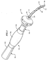
- FIG. 1 is a perspective view of a catheter according to the invention.
- FIG. 2 is a side cross-sectional view of the catheter body and tip section of a catheter according to the invention.
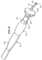
- FIG. 3 is a side cross-sectional view of the tip section of a catheter according to the invention.
- FIG. 4 is a side cross-sectional view of a portion of the tip section showing one means for anchoring the puller wires to the sides of the tip section.
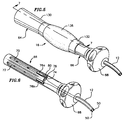
- FIG. 5 is a perspective view of a control handle according to the invention.
- FIG. 6 is a perspective view of the piston of the control handle of FIG. 5.
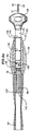
- FIG. 7 is a side partial cross-sectional view of the control handle of FIG. 5 along line 7-7.
- FIG. 8 is a perspective view of an alternative embodiment of a control handle according to the invention.
- FIG. 9A is a side cross partial cross-sectional view of the handle of FIG. 8 without the sleeve wherein only the handle housing is shown in cross section.
- FIG. 9B is a close-up side cross partial cross-sectional view of the handle of FIG. 9 with the sleeve.
- FIG. 10 is a side cross partial cross-sectional view of the handle of FIG. 8 with the sleeve wherein only the handle housing is shown in cross section.
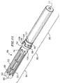
- FIG. 11 is a perspective view of the proximal end of the piston of the handle of FIGs. 8 to 10.
- FIG. 12 is a perspective view of the proximal end of the piston of FIG. 11 wherein the ring has been slid proximally along the length of the piston.
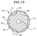
- FIG. 13 is an end cross-sectional view of the piston of FIG. 12 along line 13-13.
-
- In a particularly preferred embodiment of the invention there is provided a bidirectional
steerable catheter 10. As shown in FIGs. 1 to 4, the catheter comprises anelongated catheter body 12 having proximal and distal ends, atip section 14 at the distal end of the catheter body, and acontrol handle 16 at the proximal end of the catheter body. - With reference to FIGs. 1 and 2, the
catheter body 12 comprises an elongated tubular construction having a single, axial orcentral lumen 18. Thecatheter body 12 can have additional lumens if desired, although a singlecentral lumen 18 is presently preferred. The catheter body is flexible, i.e., bendable, but substantially non-compressible along its length. Thecatheter body 12 can be of any suitable construction and made of any suitable material. A presently preferred construction comprises anouter wall 20 made of polyurethane or PEBAX™. Theouter wall 20 comprises an imbedded braided mesh of stainless steel or the like to increase torsional stiffness of thecatheter body 12 so that, when the control handle 16 is rotated, thetip section 14 will rotate in a corresponding manner. - The outer diameter of the
catheter body 12 is not critical, but is preferably no more than about 8 french, more preferably about 7 french. Likewise, the thickness of theouter wall 20 is not critical, but is thin enough so that thecentral lumen 18 can accommodate at least two puller wires and one or more electrode lead wires. The inner surface of theouter wall 20 is lined with a stiffeningtube 22, which can be made of any suitable material, such as polyimide or nylon. The stiffeningtube 22, along with the braidedouter wall 20, provides improved torsional stability while at the same time minimizing the wall thickness of the catheter, thus maximizing the diameter of thecentral lumen 18. The outer diameter of the stiffeningtube 22 is about the same as or slightly smaller than the inner diameter of theouter wall 20. - As shown in FIGs. 2 and 3, the
tip section 14 comprises a short section oftubing 24 having anaxial lumen 26 and first and second off-axis lumens tubing 24 is made of a suitable non-toxic material that is preferably more flexible than thecatheter body 12. A presently preferred material for thetubing 24 is braided polyurethane, i.e., polyurethane with an embedded mesh of braided stainless steel or the like. The outer diameter of thetip section 14, like that of thecatheter body 12, is preferably no greater than about 8 french, more preferably about 7 french. Alternatively, thetip section 14 can have only two lumens, both off-axis lumens. A description of such a design is provided in U.S. Patent Application No. 09/205,631, entitled "Bidirectional Electrode Catheter", the disclosure of which is incorporated herein by reference. - A preferred means for attaching the
catheter body 12 to thetip section 14 is illustrated in FIG. 2. The proximal end of thetip section 14 comprises an outercircumferential notch 32 that receives the inner surface of theouter wall 20 of thecatheter body 12. Thetip section 14 andcatheter body 12 are attached by glue or the like. Before thetip section 14 andcatheter body 12 are attached, the stiffeningtube 22 is inserted into the catheter body. The distal end of the stiffeningtube 22 is fixedly attached near the distal end of thecatheter body 12 by forming a glue joint (not shown) with polyurethane glue or the like. Preferably a small distance, e.g., about 3 mm, is provided between the distal end of thecatheter body 12 and the distal end of the stiffeningtube 22 to permit room for thecatheter body 12 to receive thenotch 32 of thetip section 14. A force is applied to the proximal end of the stiffeningtube 22, and, when the stiffening tube is under compression, a first glue joint (not shown) is made between the stiffeningtube 22 and theouter wall 20 by a fast drying glue joint e.g., Super Glue™. Thereafter a second glue joint (not shown) is formed between the proximal ends of the stiffeningtube 22 andouter wall 20 using a slower drying but stronger glue, e.g., polyurethane. - If desired, a
spacer 23 can be located within the catheter body between the distal end of the stiffening tube and the proximal end of the tip section. Thespacer 23 provides a transition in flexibility at the junction of the catheter body and tip section, which allows this junction to bend smoothly without folding or kinking. A catheter having such a spacer is described in U.S. Patent Application No. 08/924,616/US-A-5 964 757, entitled "Steerable Direct Myocardial Revascularization Catheter", the disclosure of which is incorporated herein by reference. - At the distal end of the
tip section 14 is atip electrode 38. Preferably thetip electrode 38 has a diameter about the same as the outer diameter of thetubing 24. Thetip electrode 38 is attached to thetubing 24 by creating anotch 40 in the proximal end of the tip electrode, placing the proximal end of the tip electrode on the distal end of the tubing, and filling the notch with glue. - In the depicted embodiment three
ring electrodes 42 are mounted on thetubing 24 proximal to thetip electrode 38. Eachring electrode 42 is slid over thetubing 24 and fixed in place by glue or the like. It is understood that the presence, number and position of ring electrodes may vary as desired. Similarly, a tip electrode may be excluded if desired. Thetip electrode 38 andring electrodes 42. Can be made of any suitable material, and are preferably machined from platinum-iridium bar (90% platinum/10% iridium). - The
tip electrode 38 andring electrodes 42 are each connected to a separateelectrode lead wire 44. Thelead wires 44 extend through theaxial lumen 26 of thetip section 14, thecentral lumen 18 of thecatheter body 12, and the control handle 16, and terminate at their proximal end in an input jack (not shown) that may be plugged into an appropriate monitor (not shown). If desired, the portion of thelead wires 44 extending through thecentral lumen 18 of thecatheter body 12, control handle 16 and proximal end of thetip section 14 can be enclosed within a protective sheath (not shown), which can be made of any suitable material, preferably polyimide. - The !ead
wires 44 are attached to thetip electrode 38 andring electrodes 42 by any suitable conventional technique. Connection of alead wire 44 to thetip electrode 38 is accomplished, for example, by welding thelead wire 44 into ahole 46 in the tip electrode. - Connection of a
lead wire 44 to aring electrode 42 is preferably accomplished by first making a small hole through thetubing 24. Such a hole can be created, for example, by inserting a needle through thetubing 24 and heating the needle sufficiently to form a permanent hole (not shown). Alead wire 44 is then drawn through the hole by using a microhook or the like. The ends of thelead wires 44 are then stripped of any coating and soldered or welded to the underside of thering electrode 42, which is then slid into position over the hole and fixed in place with polyurethane glue or the like. - Two
puller wires 50, each having proximal and distal ends, extend through thecatheter body 12. Thepuller wires 50 are anchored at their proximal ends to the control handle 16 and at their distal ends to thetip section 14. Thepuller wires 50 are made of any suitable metal, such as stainless steel or Nitinol, and are preferably coated with Teflon™ or the like. The coating imparts lubricity to thepuller wires 50. Thepuller wires 50 preferably each have a diameter ranging from about 0.006 inch to about 0.010 inch. - Two compression coils 52 are provided in the
catheter body 12, each in surrounding relation to acorresponding puller wire 50. The compression coils 52 extend from the proximal end of thecatheter body 12 to the proximal end of thetip section 14. The compression coils 52 are made of any suitable metal, preferably stainless steel. The compression coils 52 are tightly wound on themselves to provide flexibility, i.e., bending, but to resist compression. The inner diameter of eachcompression coil 52 is preferably slightly larger than the diameter of thecorresponding puller wire 50. The Teflon™ coating on thepuller wires 50 allows them to slide freely within the compression coils 52. The outer surface of eachcompression coil 52 is covered by a flexible,non-conductive sheath 53, e.g., made of polyimide tubing, to prevent contact between the compression coils 52 and thelead wires 44. - Each
compression coil 52 is anchored at its proximal end to the proximal end of the stiffeningtube 22 in thecatheter body 12 by glue joint 54 and at its distal end to thetip settion 14 by glue joint 56. Bothglue joints catheter body 12 and thecentral lumen 18. Such a hole may be formed, for example, by a needle or the like that punctures theouter wall 20 of thecatheter body 12 and the stiffeningtube 22, which is heated sufficiently to form a permanent hole. The glue is then introduced through the hole to the outer surface of thecompression coil 52 and wicks around the outer circumference to form a glue joint about the entire circumference of the compress coil. A short section ofplastic tubing 45 is provided around thelead wires 44 near the glue joint 54 to provide the lead wires with flexibility within the glue joint Alternatively, the distal ends of the compression coils 52 can be anchored in the distal end of thecatheter body 12. - In the depicted embodiment, the
puller wires 50 extend into the first off-axis lumen 28 and second off-axis lumen 30 of thetip section 14. Eachpuller wire 50 extends through a plastic, preferably Teflon™,sheath 55, which prevents that puller wire from cutting into the wall of thetip section 14 when the tip section is deflected. Eachpuller wire 50 is anchored at its distal end to thetip electrode 38 within ablind hole 58. Preferably thepuller wires 50 are anchored in opposite sides of thetip electrode 38 so that the tip section can deflect in two opposing directions, as described in more detail below. A preferred method for anchoring eachpuller wire 50 in thetip electrode 38 is by crimping metal tubing (not shown) to the distal end of eachpuller wire 50 and soldering the metal tubing inside theblind hole 58. Other means known to those skilled in the art for anchoring thepuller wires 50 in thetip electrode 38 could also be used. - Alternatively, one or both of the
puller wires 50 can be anchored to the sides of thetip section 14. The distal ends of thepuller wires 50 comprise T-bar anchors 61 as described above and are preferably anchored byglue 62 innotches 63 in the side wall of theflexible tubing 24 as shown in FIG. 4 and as described in U.S. Patent Application Nos. 09/134,009 (entitled "Bi-Directional Steerable Catheter") and 09/099,796 (entitled "Multi-Element Tip Electrode Mapping Catheter"), the disclosures of which are incorporated herein by reference. - If desired, the
puller wires 50 can both be anchored to the same side of the tip section with one puller wire anchored proximal the other puller wire. With this design, the tip section could form a U-shaped curve. Other puller wire anchoring arrangements could also be provided to permit the tip section to deflect to form two different curves. - The control handle 16, illustrated in FIGs. 5 to 7, comprises a
handle housing 64 and apiston 66, both having proximal and distal ends. In this embodiment, thispiston 66 moves both longitudinally and rotatably with respect to thehandle housing 64. Thehousing 64 andpiston 66 preferably both comprise a rigid plastic, such as Delrin®, an acetal homopolymer commercially available from DuPont. The proximal end of thepiston 66 is slidably and rotatably mounted within a piston chamber in the distal end of thehandle housing 64. The distal end of thepiston 66 is fixedly attached to the proximal end of thecatheter body 12. Thepiston 66 has athumb control 68 at its distal end. - In the depicted embodiment, the
handle housing 64 comprises aproximal section 130 and adistal section 132. The distal end of theproximal section 130 of thehousing 64 comprises acircumferential notch 134 into which the proximal end of thedistal section 132 fits. Theproximal section 130 and thedistal section 132 can be press-fit together. If desired, thehandle housing 64 can be formed of a single piece of plastic instead of proximal and distal sections. Around thedistal section 132 of thehandle housing 64 is provided agrip piece 136 made of rubber or the like to provide comfort to the user. - As shown in FIG. 6, the piston has first and second
longitudinal grooves longitudinal grooves circumferential groove 74. Thelongitudinal grooves circumferential groove 74, creating astep 78 at the distal ends of the longitudinal grooves under the circumferential groove. - A
puller wire anchor 76 is slidably mounted within eachlongitudinal groove step 78 at the distal ends of thelongitudinal grooves circumferential groove 74. - The proximal end of each
puller wire 50 is fixedly attached to a correspondingpuller wire anchor 76 by any suitable means, for example, by soldering the puller wire into a hole in the metal rod. Alternatively, the rod can have a small hole at its distal end and a larger hole at its proximal end. Preferably, a piece of hypodermic stock or the like is crimped on the proximal end of the puller wire. The hypodermic stock fits into the larger hole in the rod, but not the smaller hole, preventing the puller wire from being pulled distally out of the rod. - An
internal passage 77 extends within thepiston 66 through which thepuller wires 50 and lead wires (not shown) extend. Two generally diagonallysmall holes 80 are provided in thestep 78, each in general alignment with one of thelongitudinal grooves internal passage 77. Thepuller wires 50 extend through theholes 80 for connection to the puller wire anchors 76. - A
set screw 82 extends radially inwardly from thehandle housing 64 into thecircumferential groove 74. When thepiston 66 andhousing 64 are in the positions shown in FIG. 7, the piston can be rotated between first and second positions relative to the housing. Rotation of thepiston 66 relative to thehousing 64 results in movement of thecircumferential groove 74 relative to theset screw 82. When thepiston 66 is in its first position, theset screw 82 is aligned with the firstlongitudinal groove 70, as shown in FIG. 7. When thepiston 66 is in its second position, theset screw 82 is aligned with the secondlongitudinal groove 72. As would be recognized by one skilled in the art, theset screw 82 could be replaced by a pin, ring or the like (for example, as described below) that is held stationary relative to thepiston 66, whether or not fixedly attached to thehandle housing 64. - Distal movement of the
piston 66 relative to thehandle housing 64 results in longitudinal movement of the piston relative to thestationary set screw 82. When theset screw 82 is in its first position (i.e., aligned with the first longitudinal groove 70) and thepiston 66 is moved distally relative to thehandle housing 64, the first longitudinal groove 70 (along with the piston) slides distally relative to the set screw, which extends radially inwardly into the first longitudinal groove. However, distal movement of the puller wire anchor 76a in the firstlongitudinal groove 70 is blocked by thestationary set screw 82. Hence, thepuller wire 50 connected to the blocked puller wire anchor 76a is also held stationary relative to thedistally moving piston 66 andcatheter body 12, which is fixedly attached to the piston. This results in deflection of thetip section 14 in the direction of the off-axis lumen puller wire 50 extends. - Similarly, when the
set screw 82 is in its second position (i.e., aligned with the second longitudinal groove 72) and thepiston 66 is moved distally relative to thehandle housing 64 and set screw, theset screw 82 blocks movement of thepuller wire anchor 76b, which remains stationary relative to the distally-moving piston. Thepuller wire 50 connected to thepuller wire anchor 76b is held stationary relative to thedistally moving piston 66 andcatheter body 12, thus deflecting thetip section 14 in the direction of the off-axis lumen - This design permits deflection of the
tip section 14 to form two different curves, and preferably to deflect in two different directions, while preventing simultaneous movement of thepuller wires 50. - As would be recognized to one skilled in the art, the above-described design could be used with a unidirectional catheter, i.e., having only a single puller wire. If only a single puller wire is included in the catheter, only a single longitudinal groove is provided in the piston. A circumferential groove is not necessary, but the set screw (or other pin) must extend into the longitudinal groove distal the puller wire anchor.
- An alternative embodiment of the inventive control handle 16 is shown in FIGs. 8 to 13. The
handle 16 comprises ahandle housing 64 and apiston assembly 65, both having proximal and distal ends. Thepiston assembly 65 comprises apiston 66 at its proximal end and athumb control 68 at its distal end, as well as additional components described in more detail below. The proximal end of thepiston assembly 65 is slidably mourned within a piston chamber in the distal end of thehandle housing 64. The distal end of thepiston assembly 65 is fixedly attached to the proximal end of thecatheter body 12. Thepiston 66 comprises aninternal passage 77 extending therethrough through which thepuller wires 50 and lead wires (not shown) extend. - The
handle housing 64 comprises aproximal section 130 and adistal section 132. The distal end of theproximal section 130 of thehousing 64 comprises acircumferential notch 134 into which the proximal end of thedistal section 132 fits. Theproximal section 130 and thedistal section 132 can be press-fit together. Around thedistal section 132 of thehandle housing 64 is provided agrip piece 136 made of rubber or the like to provide comfort to the user. - The piston chamber has a first
inner diameter 138, a secondinner diameter 140, and a thirdinner diameter 142. The firstinner diameter 138 is proximal the secondinner diameter 140, both of which are distal the thirdinner diameter 142. The secondinner diameter 140 is smaller than the firstinner diameter 138, but is only slightly larger than the outer diameter of thepiston 66. The thirdinner diameter 142 is smaller than the firstinner diameter 138 and preferably similar in size to the secondinner diameter 140. - FIG. 11 shows the proximal portion of the
piston assembly 65, which comprises aproximal section 84, adistal section 86, and acircumferential recess 85 between the proximal section and distal section. Theproximal section 84 comprises a series of longitudinal grooves, including deeplongitudinal grooves 88 and shallowlongitudinal grooves 90, about its entire circumference. The depicted embodiment has two deeplongitudinal grooves 88 and four shallowlongitudinal grooves 90, as shown best in FIG. 13. The two deeplongitudinal grooves 88 are adjacent to each other. Thelongitudinal grooves walls 92. Each dividingwall 92 has an angleddistal end 94. - A
puller wire anchor 76 is slidably disposed within each deeplongitudinal groove 88. The distal ends of the deeplongitudinal grooves 88 terminate in avertical wall 79. Eachvertical wall 79 contains a small hole (not shown). Twopuller wires 50 extend through theinternal passage 77 and through one of the small holes so that the puller wires can be attached to the puller wire anchors 76 as described above. - The
distal section 86, which has proximal and distal ends, is spaced apart from theproximal section 84 by thecircumferential recess 85. The proximal end of thedistal section 86 comprises a plurality of tooth-shapednotches 96. Preferably the number of tooth-shapednotches 96 is the same as the number of dividingwalls 92, which in the depicted embodiment is six. - The
piston assembly 65 further comprises aring 98 rotatably mounted on thepiston 66. Thering 98 is preferably made of a generally rigid plastic, such as Delrin®, acrylonitrilebutadiene-styrene resin, polyester, polyethylene or the like. Thering 98 has aproximal end 104 and adistal end 106. The outer diameter of thering 98 is slightly greater than the outer diameter of the distal portion of thepiston 66. The inner diameter of thering 98 is slightly greater than the outer diameter of thecircumferential recess 85. - The
ring 98 has a plurality ofprojections 110 that extend radially inwardly into thecircumferential recess 85 and that are sized to be received by thelongitudinal grooves ring 98 slid proximally so that it is positioned over thelongitudinal grooves projections 110 extending inwardly into the grooves. As can be seen from FIG. 13, theprojections 110 are spaced apart so that they can be aligned with every otherlongitudinal groove projections 110 are provided on thering 98. - The
distal end 106 of thering 98 comprises a plurality ofteeth 108 spaced apart to be aligned with everyother notch 96. Accordingly, the number ofteeth 108 is equal to half the number ofnotches 96. In the depicted embodiment thering 98 contains threeteeth 108. Theteeth 108 have a thickness so they project inward, preferably to about the same depth as theprojections 110. - As shown in FIG. 10, the
piston assembly 65 further comprises acylindrical sleeve 114 disposed about thedistal section 86 of thepiston 66. Thesleeve 114, which has proximal and distal ends, is preferably made of a generally rigid plastic, such as Delrin®, polycarbonate or the like. The proximal end of thesleeve 114 contains three tooth-shapednotches 116 round its circumference that generally correspond in size, shape and position to the threeteeth 108 on thedistal end 106 of thering 98. Thus, the proximal end of thesleeve 114 fits against the top or outer portion of thering 98, and theprojections 110 on the ring fit against thenotches 96 on the proximal end of thedistal section 86 of the piston. If the number ofteeth 108 on thering 98 is increased or decreased, the number of tooth-shapednotches 116 on thesleeve 114 is correspondingly increased or decreased. Thering 98 andsleeve 114 rotate together about thepiston 66 due to the interlocking between the tooth-shapednotches 116 on the sleeve and theteeth 108 on the ring. Preferably, thepiston 66 comprises acircumferential groove 57 into which an o-ring (not shown) fits to seal the space between the piston and the sleeve. - The
ring 98 andsleeve 114 have approximately the same outer diameter, which is smaller than the firstinner diameter 138 of the piston chamber but larger than the second andthird diameters inner diameter 138 and the secondinner diameter 140, thehandle housing 64 comprises a distalcylindrical flange 139 at the distal end of the piston chamber to prevent distal movement of the sleeve 114 (and thus the ring 98) relative to the housing, which also prevents distal movement of the sleeve out of the piston chamber. Due to the difference between the firstinner diameter 138 and the thirdinner diameter 142, thehandle housing 64 comprises a proximal cylindrical flange 141 midway trough the piston chamber to prevent proximal movement of the ring 98 (and thus the sleeve 114) relative to the housing. - Movement of the
piston 66 distally relative to thehandle housing 64, e.g., by pushing on thethumb rest 68, results in the piston sliding distally relative to thesleeve 114 andring 98 so that the ring is positioned over thelongitudinal grooves circumferential recess 85, as shown in FIG. 12. As thepiston 66 moves distally, theprojections 110 on thering 98 are received by every other of thelongitudinal grooves projection 110 will be received by one of the deeplongitudinal grooves 88, but not the other. As thepiston 66 moves distally relative to thering 98, theprojection 110 extending into the deeplongitudinal groove 88 engages and blocks thepuller wire anchor 76 in that groove, holding it and its associatedpuller wire 50 stationary relative to the distally-movingpiston 66. Such movement results in deflection of thetip section 14 in the direction of the off-axis lumen into which the distal end of thepuller wire 50 extends. As would be recognized by one skilled in the art, thering 98 can be engaged by thehandle housing 64 in any other manner such that the distal or proximal movement of thepiston 66 relative to the housing causes the ring to remain longitudinally stationary relative to the distally or proximally moving piston, but still rotatable on the piston. - To engage the
puller wire anchor 76b in the adjacent deeplongitudinal groove 88, and thus enable deflection of the tip section in the direction of the off-axis lumen of theother puller wire 50, theprojections 110 must be moved into alignment with the adjacent longitudinal grooves. To accomplish this, thepiston 66 is moved proximally relative to thehandle housing 64 until theteeth 108 on thering 98 engage the tooth shapednotches 96 on the proximal end of the distal section of thepiston 86. Because of the shapes of theteeth 108 and thenotches 96, thering 98 rotates as theteeth 108 engage thenotches 96. The amount of rotation results in theprojections 110 on thering 98 being aligned with the adjacentlongitudinal grooves 88. - As the
piston 64 is again moved distally relative to thehandle housing 64 andring 98, theprojections 110 are received by the adjacentlongitudinal grooves projection 110 received by the deeplongitudinal groove 88 engages and blocks distal movement of thepuller wire anchor 76b in that groove, holding it stationary relative to the distally-movingpiston 66 in a manner similar to that described above. This also holds thepuller wire 50 anchored to thatpuller wire anchor 76b stationary relative to the distally-movingpiston 66 andcatheter body 12, resulting in deflection of thetip section 14 in the direction of the off-axis lumen into which that puller wire extends. - When it is desired to again deflect the
tip section 14 in the direction of thepuller wire 50 in the first deeplongitudinal groove 88, thepiston 66 is again moved proximally until theteeth 108 on thering 98 engage the tooth shapednotches 96. Thering 98 again rotates relative to thepiston 66 as theteeth 108 of the ring engage thenotches 96. Adifferent projection 110 then comes into alignment with the first deeplongitudinal groove 88. - In a particularly preferred embodiment, an identification mechanism is provided so that the physician can readily ascertain which
puller wire 50 is engaged. A preferred mechanism comprises threeholes 118 spaced 120° apart around the circumference of thesleeve 114 near its distal end, as shown in FIG. 10. Thesleeve 114 is a different color than thepiston 66. Thedistal section 132 of thehandle housing 64 has ahole 120 generally positioned in line with theholes 118 so that one of theholes 118 can be aligned with thehole 120. As thesleeve 114 rotates relative to thepiston 66 andhousing 64, it is positioned in one of six positions relative to the piston and housing. In three of those positions, one of theholes 118 is aligned with thehole 120 so that the user can see thepiston 66 through thehole 120. These three positions correspond to one of the puller wires being blocked. In the other three positions, which correspond to the other puller wire being blocked, the user sees thesleeve 114 through thehole 120. By this design, the user can determine which puller wire is blocked, and thus how the tip section will deflect by seeing either the color of the sleeve or the color of the piston through thehole 120 in the handle housing. - If desired, a set screw (not shown) can be provided to assure that the
piston 66 is not separated from thehandle housing 64. For example, the set screw could extend through thehandle housing 64 and into one of the shallowlongitudinal grooves 90 of thepiston 66. Other means for assuring that the piston is not separated from the handle housing can also be used. - As would be recognized by one skilled in the art, the
ring 98 andsleeve 114 could be replaced with a single piece that performs all of the functions of the ring and sleeve described above. Alternatively, thesleeve 114 could be removed altogether. With such a design, the length of thedistal section 130 of thehandle housing 64 having the firstinner diameter 138 would be decreased so that the secondinner diameter 140 is much closer to thering 98. - Additionally, the above-described handle designs can be used with a multidirectional catheter having more than two puller wires. In the design of FIGs. 5 to 7, the number of longitudinal grooves (and puller wire anchors) would be increased to correspond to the number of puller wires. In the design of FIGs. 8 to 13, the number of deep longitudinal grooves (and puller wire anchors) would be increased to correspond to the number of puller wires. To prevent simultaneous movement of the tip section in the directions of two different puller wires, the number of protrusions on the ring would be modified so that only one protrusion extends into one of the deep longitudinal grooves. Thus, for example, if three puller wires are used, the protrusions on the ring would be aligned with every third longitudinal groove. If four puller wires are used, the piston would be modified to have four deep longitudinal grooves and four shallow longitudinal grooves, and the protrusions on the ring would be aligned with every fourth longitudinal groove.
- It may also be desirable to permit simultaneous movement of two or more puller wires, for example, to permit curvature of the tip section in two directions simultaneously, for example, as disclosed in U.S. Patent Application No. 08924,611, entitled "Omni-Directional Steerable Catheter", the disclosure of which is incorporated herein by reference. Other similar modifications would be obvious to one skilled in the art.
- The preceding description has been presented with reference to presently preferred embodiments of the invention. Workers skilled in the art and technology to which this invention pertains will appreciate that alterations and changes in the described structure may be practiced without meaningfully departing from the principal, spirit and scope of this invention. For example, the deep longitudinal grooves need not be adjacent each other. Alternatively, all of the longitudinal grooves can be of the same depth, similar to the deep longitudinal grooves. Additionally the ring can contain more or less teeth as desired, but preferably a number equal to the number of protrusions on the ring for simplicity in manufacturing the ring.
- Accordingly, the foregoing description should not be read as pertaining only to the precise structures described and illustrated in the accompanying drawings, but rather should be read consistent with and as support to the following claims which are to have their fullest and fair scope.
Claims (10)
- A multi-directional steerable catheter comprising:a catheter body having a tubular wall, proximal and distal ends, and at least one lumen extending therethrough;a tip section comprising a flexible tubing having proximal and distal ends and at least one lumen extending therethrough, the proximal end of the tip section being fixedly attached to the distal end of the catheter body;a control handle having proximal and distal ends mounted at its distal end to the proximal end of the catheter body comprising:a housing having proximal and distal ends and a piston chamber extending therethrough, the piston chamber having proximal and distal ends;a piston assembly having proximal and distal portions slidably mounted in the piston chamber of the housing and longitudinally movable between proximal and distal positions, the distal portion of the piston assembly being fixedly attached to the proximal end of the catheter body, and the proximal portion comprising:a distal section having proximal and distal ends comprising a plurality of notches at its proximal end;a proximal section comprising a plurality of longitudinal grooves about its entire circumference separated by dividing walls having angled distal ends;a circumferential recess between the proximal section and distal section;a ring having proximal and distal ends and rotatably mounted on the piston assembly, the ring comprising a plurality of projections that extend radially inwardly into the circumferential recess and that are capable of being received by the longitudinal grooves, wherein the number of projections is less than the number of longitudinal grooves, and further comprising a plurality of teeth at its distal end capable of being received by the notches; andfirst and second puller wire anchors, each puller wire anchor slidably disposed within a corresponding longitudinal groove;first and second puller wires having proximal and distal ends, each puller wire extending from the control handle, through a lumen in the catheter body and into a lumen in the tip section, the proximal end of each puller wire being fixedly attached to a separate puller wire anchor in the control handle;first means for causing deflection of the tip section to form a first curve in response to proximal movement of the first puller wire relative to the catheter body;second means for causing deflection of the tip section to form a second curve different from the first curve in response to proximal movement of the second puller wire relative to the catheter body;
wherein distal movement of the piston relative to the handle housing results in a projection on the ring extending in one of the longitudinal grooves to thereby prevent longitudinal movement of the puller wire anchor in the groove relative to the handle housing, causing deflection of the tip section in the direction of the lumen into which the puller wire connected to that anchor extends, and further wherein proximal movement of the piston relative to the handle housing causes rotation of the ring, thereby aligning that same projection with a different longitudinal groove to thereby prevent longitudinal movement of the puller wire anchor in the groove relative to the handle housing, causing deflection of the tip section in the direction of the lumen into which the puller wire connected to that anchor extends. - A catheter according to claim 1, having more than two puller wire anchors and more than two puller wires.
- A catheter according to claim 1, wherein the number of projections on the ring is equal to half the number of longitudinal grooves.
- A catheter according to claim 1, wherein the ring has three projections and the distal section of the piston assembly has six longitudinal grooves.
- A catheter according to claim 1, wherein the first and second means for causing deflection of the tip section comprise anchors that anchor the puller wires to the side of the tip section.
- A catheter according to claim 1, further comprising a tip electrode.
- A catheter according to claim 6, wherein the means for causing deflection of the tip section comprises solder that anchors the puller wire to the tip electrode.
- A catheter according to claim 1, further comprising means for maintaining the ring in the piston chamber.
- A catheter according to claim 8, wherein the maintaining means comprises a cylindrical flange near the distal end of the piston chamber.
- A catheter according to claim 1, comprising two puller wires that extend into opposing off-axis lumens in the tip section.
Applications Claiming Priority (2)
| Application Number | Priority Date | Filing Date | Title |
|---|---|---|---|
| US273679 | 1999-03-22 | ||
| US09/273,679 US6183435B1 (en) | 1999-03-22 | 1999-03-22 | Multi-directional steerable catheters and control handles |
Publications (2)
| Publication Number | Publication Date |
|---|---|
| EP1038546A1 true EP1038546A1 (en) | 2000-09-27 |
| EP1038546B1 EP1038546B1 (en) | 2005-09-28 |
Family
ID=23044959
Family Applications (1)
| Application Number | Title | Priority Date | Filing Date |
|---|---|---|---|
| EP00302299A Expired - Lifetime EP1038546B1 (en) | 1999-03-22 | 2000-03-21 | Multi-directional steerable catheters with control handle |
Country Status (5)
| Country | Link |
|---|---|
| US (1) | US6183435B1 (en) |
| EP (1) | EP1038546B1 (en) |
| JP (1) | JP2000312720A (en) |
| AT (1) | ATE305323T1 (en) |
| DE (1) | DE60022808T2 (en) |
Cited By (1)
| Publication number | Priority date | Publication date | Assignee | Title |
|---|---|---|---|---|
| US8024042B2 (en) | 2009-10-23 | 2011-09-20 | Medtronic, Inc. | Minimum ventricular pacing to break the repetitive AR-VS pattern |
Families Citing this family (149)
| Publication number | Priority date | Publication date | Assignee | Title |
|---|---|---|---|---|
| US6482221B1 (en) * | 2000-08-21 | 2002-11-19 | Counter Clockwise, Inc. | Manipulatable delivery catheter for occlusive devices (II) |
| US6726700B1 (en) | 2000-08-21 | 2004-04-27 | Counter Clockwise, Inc. | Manipulatable delivery catheter for occlusive devices |
| US6979312B2 (en) * | 2001-04-12 | 2005-12-27 | Biotran Corporation, Inc. | Steerable sheath catheters |
| US6913594B2 (en) * | 2001-12-31 | 2005-07-05 | Biosense Webster, Inc. | Dual-function catheter handle |
| US6733499B2 (en) | 2002-02-28 | 2004-05-11 | Biosense Webster, Inc. | Catheter having circular ablation assembly |
| US7192415B2 (en) * | 2002-03-22 | 2007-03-20 | Scimed Life Systems, Inc. | Drainage catheter with visual indicator and/or lock system |
| US7588568B2 (en) * | 2002-07-19 | 2009-09-15 | Biosense Webster, Inc. | Atrial ablation catheter and method for treating atrial fibrillation |
| US7004937B2 (en) * | 2002-07-31 | 2006-02-28 | Cryocor, Inc. | Wire reinforced articulation segment |
| US20040034365A1 (en) * | 2002-08-16 | 2004-02-19 | Lentz David J. | Catheter having articulation system |
| US7819866B2 (en) | 2003-01-21 | 2010-10-26 | St. Jude Medical, Atrial Fibrillation Division, Inc. | Ablation catheter and electrode |
| US7163537B2 (en) * | 2003-06-02 | 2007-01-16 | Biosense Webster, Inc. | Enhanced ablation and mapping catheter and method for treating atrial fibrillation |
| US7235070B2 (en) * | 2003-07-02 | 2007-06-26 | St. Jude Medical, Atrial Fibrillation Division, Inc. | Ablation fluid manifold for ablation catheter |
| US7101362B2 (en) * | 2003-07-02 | 2006-09-05 | St. Jude Medical, Atrial Fibrillation Division, Inc. | Steerable and shapable catheter employing fluid force |
| US7678104B2 (en) * | 2003-07-17 | 2010-03-16 | Biosense Webster, Inc. | Ultrasound ablation catheter and method for its use |
| US10182734B2 (en) * | 2003-07-18 | 2019-01-22 | Biosense Webster, Inc. | Enhanced ablation and mapping catheter and method for treating atrial fibrillation |
| US6926711B2 (en) * | 2003-07-30 | 2005-08-09 | Cryocor, Inc. | Articulating catheter for cryoablation with reduced diameter section |
| DE10337580B4 (en) * | 2003-08-16 | 2009-07-02 | Dr. Osypka Gmbh | Catheter with elastically bendable or steerable end |
| US20050119644A1 (en) * | 2003-12-01 | 2005-06-02 | Koerner Richard J. | Articulating catheter tip with wedge-cuts |
| US7637903B2 (en) * | 2004-02-09 | 2009-12-29 | Cryocor, Inc. | Catheter articulation segment with alternating cuts |
| US20050177131A1 (en) * | 2004-02-09 | 2005-08-11 | Lentz David J. | Catheter articulation segment with alternating cuts |
| US8007495B2 (en) * | 2004-03-31 | 2011-08-30 | Biosense Webster, Inc. | Catheter for circumferential ablation at or near a pulmonary vein |
| US20050283179A1 (en) * | 2004-06-17 | 2005-12-22 | Lentz David J | Introducer sheath |
| US7374553B2 (en) * | 2004-06-24 | 2008-05-20 | Cryocor, Inc. | System for bi-directionally controlling the cryo-tip of a cryoablation catheter |
| US7285108B2 (en) * | 2004-06-24 | 2007-10-23 | Cryocor, Inc. | Active system for deflecting a distal portion of a catheter into a hoop configuration |
| US7357797B2 (en) * | 2004-06-30 | 2008-04-15 | Cryocor, Inc. | System and method for varying return pressure to control tip temperature of a cryoablation catheter |
| US7717875B2 (en) | 2004-07-20 | 2010-05-18 | St. Jude Medical, Atrial Fibrillation Division, Inc. | Steerable catheter with hydraulic or pneumatic actuator |
| US20060047245A1 (en) * | 2004-08-24 | 2006-03-02 | Ruchir Sehra | Catheter control unit |
| US8583260B2 (en) | 2004-12-28 | 2013-11-12 | St. Jude Medical, Atrial Fibrillation Division, Inc. | Long travel steerable catheter actuator |
| US8858495B2 (en) | 2004-12-28 | 2014-10-14 | St. Jude Medical, Atrial Fibrillation Division, Inc. | Five degree of freedom ultrasound catheter and catheter control handle |
| US7691095B2 (en) | 2004-12-28 | 2010-04-06 | St. Jude Medical, Atrial Fibrillation Division, Inc. | Bi-directional steerable catheter control handle |
| US7591784B2 (en) * | 2005-04-26 | 2009-09-22 | St. Jude Medical, Atrial Fibrillation Division, Inc. | Bi-directional handle for a catheter |
| US7819868B2 (en) * | 2005-06-21 | 2010-10-26 | St. Jude Medical, Atrial Fibrilation Division, Inc. | Ablation catheter with fluid distribution structures |
| US8777929B2 (en) | 2005-06-28 | 2014-07-15 | St. Jude Medical, Atrial Fibrillation Division, Inc. | Auto lock for catheter handle |
| US7465288B2 (en) * | 2005-06-28 | 2008-12-16 | St. Jude Medical, Atrial Fibrillation Division, Inc. | Actuation handle for a catheter |
| JP2007018615A (en) * | 2005-07-08 | 2007-01-25 | Sony Corp | Storage device and semiconductor device |
| US20070060997A1 (en) * | 2005-09-15 | 2007-03-15 | Jan De Boer | Multi-lumen steerable catheter |
| US9445784B2 (en) | 2005-09-22 | 2016-09-20 | Boston Scientific Scimed, Inc | Intravascular ultrasound catheter |
| JP4905647B2 (en) * | 2006-02-14 | 2012-03-28 | 朝日インテック株式会社 | Medical tools |
| EP2021063B1 (en) | 2006-05-19 | 2013-05-15 | Boston Scientific Limited | Control mechanism for steerable medical device |
| EP2397108B1 (en) * | 2006-09-08 | 2013-08-07 | Edwards Lifesciences Corporation | Apparatus for treating a defective heart valve |
| US20080161843A1 (en) * | 2006-10-16 | 2008-07-03 | Clague Cynthia T | Vessel support device and method of vessel harvesting |
| JP4706008B2 (en) * | 2006-10-26 | 2011-06-22 | 有限会社リバー精工 | Cardiac catheter |
| US9232959B2 (en) | 2007-01-02 | 2016-01-12 | Aquabeam, Llc | Multi fluid tissue resection methods and devices |
| US9370640B2 (en) | 2007-09-12 | 2016-06-21 | Novasentis, Inc. | Steerable medical guide wire device |
| US20090131886A1 (en) | 2007-11-16 | 2009-05-21 | Liu Y King | Steerable vertebroplasty system |
| US20090131867A1 (en) | 2007-11-16 | 2009-05-21 | Liu Y King | Steerable vertebroplasty system with cavity creation element |
| WO2011066465A1 (en) * | 2009-11-25 | 2011-06-03 | Osseon Therapeutics, Inc. | Steerable and curvable vertebroplasty system with clog-resistant exit ports |
| US20090131950A1 (en) * | 2007-11-16 | 2009-05-21 | Liu Y King | Vertebroplasty method with enhanced control |
| US20090299282A1 (en) * | 2007-11-16 | 2009-12-03 | Osseon Therapeutics, Inc. | Steerable vertebroplasty system with a plurality of cavity creation elements |
| US9510885B2 (en) | 2007-11-16 | 2016-12-06 | Osseon Llc | Steerable and curvable cavity creation system |
| US20090182427A1 (en) * | 2007-12-06 | 2009-07-16 | Osseon Therapeutics, Inc. | Vertebroplasty implant with enhanced interfacial shear strength |
| US8137336B2 (en) | 2008-06-27 | 2012-03-20 | Boston Scientific Scimed, Inc. | Steerable medical device |
| US20090299352A1 (en) * | 2007-12-21 | 2009-12-03 | Boston Scientific Scimed, Inc. | Steerable laser-energy delivery device |
| US7780648B2 (en) | 2007-12-28 | 2010-08-24 | Boston Scientific Scimed, Inc. | Controlling movement of distal portion of medical device |
| US8602959B1 (en) | 2010-05-21 | 2013-12-10 | Robert Park | Methods and devices for delivery of radiation to the posterior portion of the eye |
| US8608632B1 (en) | 2009-07-03 | 2013-12-17 | Salutaris Medical Devices, Inc. | Methods and devices for minimally-invasive extraocular delivery of radiation and/or pharmaceutics to the posterior portion of the eye |
| US20110207987A1 (en) * | 2009-11-02 | 2011-08-25 | Salutaris Medical Devices, Inc. | Methods And Devices For Delivering Appropriate Minimally-Invasive Extraocular Radiation |
| US9873001B2 (en) | 2008-01-07 | 2018-01-23 | Salutaris Medical Devices, Inc. | Methods and devices for minimally-invasive delivery of radiation to the eye |
| US10022558B1 (en) | 2008-01-07 | 2018-07-17 | Salutaris Medical Devices, Inc. | Methods and devices for minimally-invasive delivery of radiation to the eye |
| WO2009089288A1 (en) | 2008-01-07 | 2009-07-16 | Salutaris Md | Methods and devices for minimally-invasive extraocular delivery of radiation to the posterior portion of the eye |
| US9056201B1 (en) | 2008-01-07 | 2015-06-16 | Salutaris Medical Devices, Inc. | Methods and devices for minimally-invasive delivery of radiation to the eye |
| EP2259742B1 (en) | 2008-03-06 | 2020-01-01 | AquaBeam LLC | Tissue ablation and cautery with optical energy carried in fluid stream |
| US8048024B2 (en) | 2008-03-17 | 2011-11-01 | Boston Scientific Scimed, Inc. | Steering mechanism |
| US8048025B2 (en) * | 2008-07-07 | 2011-11-01 | Boston Scientific Scimed, Inc. | Multi-plane motion control mechanism |
| US8834357B2 (en) | 2008-11-12 | 2014-09-16 | Boston Scientific Scimed, Inc. | Steering mechanism |
| US8372033B2 (en) | 2008-12-31 | 2013-02-12 | St. Jude Medical, Atrial Fibrillation Division, Inc. | Catheter having proximal heat sensitive deflection mechanism and related methods of use and manufacturing |
| USD691270S1 (en) | 2009-01-07 | 2013-10-08 | Salutaris Medical Devices, Inc. | Fixed-shape cannula for posterior delivery of radiation to an eye |
| USD691267S1 (en) | 2009-01-07 | 2013-10-08 | Salutaris Medical Devices, Inc. | Fixed-shape cannula for posterior delivery of radiation to eye |
| USD691269S1 (en) | 2009-01-07 | 2013-10-08 | Salutaris Medical Devices, Inc. | Fixed-shape cannula for posterior delivery of radiation to an eye |
| USD691268S1 (en) | 2009-01-07 | 2013-10-08 | Salutaris Medical Devices, Inc. | Fixed-shape cannula for posterior delivery of radiation to eye |
| WO2013130895A1 (en) | 2012-02-29 | 2013-09-06 | Aquabeam, Llc | Automated image-guided tissue resection and treatment |
| US20100298832A1 (en) | 2009-05-20 | 2010-11-25 | Osseon Therapeutics, Inc. | Steerable curvable vertebroplasty drill |
| US8906013B2 (en) | 2010-04-09 | 2014-12-09 | Endosense Sa | Control handle for a contact force ablation catheter |
| US9795765B2 (en) | 2010-04-09 | 2017-10-24 | St. Jude Medical International Holding S.À R.L. | Variable stiffness steering mechanism for catheters |
| JP4679668B1 (en) * | 2010-04-21 | 2011-04-27 | 日本ライフライン株式会社 | catheter |
| WO2011137377A1 (en) | 2010-04-29 | 2011-11-03 | Dfine, Inc. | System for use in treatment of vertebral fractures |
| US20120191079A1 (en) | 2011-01-20 | 2012-07-26 | Hansen Medical, Inc. | System and method for endoluminal and translumenal therapy |
| US9592091B2 (en) | 2011-08-30 | 2017-03-14 | Biosense Webster (Israel) Ltd. | Ablation catheter for vein anatomies |
| US9757538B2 (en) | 2011-12-15 | 2017-09-12 | Imricor Medical Systems, Inc. | MRI compatible control handle for steerable sheath with audible, tactile and/or visual means |
| US9821143B2 (en) | 2011-12-15 | 2017-11-21 | Imricor Medical Systems, Inc. | Steerable sheath including elastomeric member |
| US20140135745A1 (en) | 2011-12-15 | 2014-05-15 | Imricor Medical Systems, Inc. | Mri compatible handle and steerable sheath |
| USD737966S1 (en) | 2012-01-20 | 2015-09-01 | Olympus Corporation | Endoscope |
| US9010320B2 (en) | 2012-03-12 | 2015-04-21 | Furman Medical Llc | Manually articulated intubation stylet, intubation device and intubation method |
| JP2015130898A (en) | 2012-04-27 | 2015-07-23 | テルモ株式会社 | operation member |
| USD749725S1 (en) * | 2012-09-21 | 2016-02-16 | Lsi Solutions, Inc. | Handheld uterine manipulator with cervical cup |
| US9694161B2 (en) * | 2012-11-14 | 2017-07-04 | Biosense Webster (Israel), Ltd. | Catheter with flat beam providing nonsymmetrical curve bi-directional deflection |
| USD749211S1 (en) * | 2012-12-14 | 2016-02-09 | Conmed Corporation | Keyway portion |
| US9050010B2 (en) | 2012-12-31 | 2015-06-09 | Biosense Webster (Israel) Ltd. | Double loop lasso with single puller wire for bi-directional actuation |
| US10231867B2 (en) | 2013-01-18 | 2019-03-19 | Auris Health, Inc. | Method, apparatus and system for a water jet |
| US9855404B2 (en) | 2013-05-03 | 2018-01-02 | St. Jude Medical International Holding S.À R.L. | Dual bend radii steering catheter |
| WO2014201165A1 (en) | 2013-06-11 | 2014-12-18 | Auris Surgical Robotics, Inc. | System for robotic assisted cataract surgery |
| US10426661B2 (en) | 2013-08-13 | 2019-10-01 | Auris Health, Inc. | Method and apparatus for laser assisted cataract surgery |
| US9833596B2 (en) | 2013-08-30 | 2017-12-05 | Novasentis, Inc. | Catheter having a steerable tip |
| USD755383S1 (en) * | 2013-09-23 | 2016-05-03 | Aesculap Ag | Handpiece |
| KR101374320B1 (en) * | 2013-10-15 | 2014-03-17 | 홍문기 | Steerable electrode catheter assembly |
| US9468407B2 (en) | 2014-05-30 | 2016-10-18 | Biosense Webster (Israel) Ltd. | Catheter with distal section having side-by-side loops |
| US9820664B2 (en) | 2014-11-20 | 2017-11-21 | Biosense Webster (Israel) Ltd. | Catheter with high density electrode spine array |
| US11033716B2 (en) | 2015-01-12 | 2021-06-15 | Intuitive Surgical Operations, Inc. | Devices, systems, and methods for anchoring actuation wires to a steerable instrument |
| US20160287279A1 (en) | 2015-04-01 | 2016-10-06 | Auris Surgical Robotics, Inc. | Microsurgical tool for robotic applications |
| US10537259B2 (en) | 2015-06-29 | 2020-01-21 | Biosense Webster (Israel) Ltd. | Catheter having closed loop array with in-plane linear electrode portion |
| US9949656B2 (en) | 2015-06-29 | 2018-04-24 | Biosense Webster (Israel) Ltd. | Catheter with stacked spine electrode assembly |
| US10575742B2 (en) | 2015-06-30 | 2020-03-03 | Biosense Webster (Israel) Ltd. | Catheter having closed electrode assembly with spines of uniform length |
| US9955986B2 (en) | 2015-10-30 | 2018-05-01 | Auris Surgical Robotics, Inc. | Basket apparatus |
| US9949749B2 (en) | 2015-10-30 | 2018-04-24 | Auris Surgical Robotics, Inc. | Object capture with a basket |
| US10231793B2 (en) | 2015-10-30 | 2019-03-19 | Auris Health, Inc. | Object removal through a percutaneous suction tube |
| US9907480B2 (en) | 2016-02-08 | 2018-03-06 | Biosense Webster (Israel) Ltd. | Catheter spine assembly with closely-spaced bipole microelectrodes |
| US10675443B2 (en) | 2016-03-07 | 2020-06-09 | St. Jude Medical, Cardiology Division, Inc. | Medical device including an actuator restraining assembly |
| USD815285S1 (en) | 2016-05-11 | 2018-04-10 | Salutaris Medical Devices, Inc. | Brachytherapy device |
| USD814637S1 (en) | 2016-05-11 | 2018-04-03 | Salutaris Medical Devices, Inc. | Brachytherapy device |
| USD814638S1 (en) | 2016-05-11 | 2018-04-03 | Salutaris Medical Devices, Inc. | Brachytherapy device |
| USD808529S1 (en) | 2016-08-31 | 2018-01-23 | Salutaris Medical Devices, Inc. | Holder for a brachytherapy device |
| USD808528S1 (en) | 2016-08-31 | 2018-01-23 | Salutaris Medical Devices, Inc. | Holder for a brachytherapy device |
| JP2019534130A (en) | 2016-10-27 | 2019-11-28 | ディーファイン,インコーポレイティド | Articulated osteotome with cement delivery channel |
| JP7256119B2 (en) | 2016-11-28 | 2023-04-11 | ディファイン インコーポレイテッド | Tumor resection device and related method |
| EP3551100B1 (en) | 2016-12-09 | 2021-11-10 | Dfine, Inc. | Medical devices for treating hard tissues |
| WO2018129180A1 (en) | 2017-01-06 | 2018-07-12 | Dfine, Inc. | Osteotome with a distal portion for simultaneous advancement and articulation |
| US10786651B2 (en) | 2017-03-07 | 2020-09-29 | Talon Medical, LLC | Steerable guide catheter |
| WO2018183393A1 (en) * | 2017-03-28 | 2018-10-04 | Auris Health, Inc. | Shaft actuating handle |
| KR102550962B1 (en) | 2017-04-07 | 2023-07-06 | 아우리스 헬스, 인코포레이티드 | Align the patient introducer |
| US10285574B2 (en) | 2017-04-07 | 2019-05-14 | Auris Health, Inc. | Superelastic medical instrument |
| US11517715B2 (en) * | 2018-01-02 | 2022-12-06 | Biosense Webster (Israel) Ltd. | Deflectable medical probe |
| KR102579505B1 (en) | 2018-06-07 | 2023-09-20 | 아우리스 헬스, 인코포레이티드 | Robotic medical system with high-power instruments |
| JP7391886B2 (en) | 2018-06-28 | 2023-12-05 | オーリス ヘルス インコーポレイテッド | Medical system incorporating pulley sharing |
| US10828118B2 (en) | 2018-08-15 | 2020-11-10 | Auris Health, Inc. | Medical instruments for tissue cauterization |
| CN112566567A (en) | 2018-08-17 | 2021-03-26 | 奥瑞斯健康公司 | Bipolar medical instrument |
| WO2020068303A1 (en) | 2018-09-26 | 2020-04-02 | Auris Health, Inc. | Systems and instruments for suction and irrigation |
| US11576738B2 (en) | 2018-10-08 | 2023-02-14 | Auris Health, Inc. | Systems and instruments for tissue sealing |
| WO2020097339A1 (en) | 2018-11-08 | 2020-05-14 | Dfine, Inc. | Tumor ablation device and related systems and methods |
| US11950863B2 (en) | 2018-12-20 | 2024-04-09 | Auris Health, Inc | Shielding for wristed instruments |
| CN109498151A (en) * | 2019-01-04 | 2019-03-22 | 科塞尔医疗科技(苏州)有限公司 | A kind of multistage curved electrophysiologicalcatheter catheter of tune |
| WO2020154100A1 (en) | 2019-01-25 | 2020-07-30 | Auris Health, Inc. | Vessel sealer with heating and cooling capabilities |
| JP2022528810A (en) | 2019-03-18 | 2022-06-15 | バイオセンス・ウエブスター・(イスラエル)・リミテッド | Electrode configuration for arrhythmia diagnosis |
| EP3908201B1 (en) | 2019-03-25 | 2024-04-24 | Auris Health, Inc. | Instruments for medical stapling |
| US11850051B2 (en) | 2019-04-30 | 2023-12-26 | Biosense Webster (Israel) Ltd. | Mapping grid with high density electrode array |
| CN110037829B (en) * | 2019-05-30 | 2022-08-16 | 北京华脉泰科医疗器械股份有限公司 | Medical fixator conveyor and fixing system |
| US11369386B2 (en) | 2019-06-27 | 2022-06-28 | Auris Health, Inc. | Systems and methods for a medical clip applier |
| US11109928B2 (en) | 2019-06-28 | 2021-09-07 | Auris Health, Inc. | Medical instruments including wrists with hybrid redirect surfaces |
| US11896330B2 (en) | 2019-08-15 | 2024-02-13 | Auris Health, Inc. | Robotic medical system having multiple medical instruments |
| US11471650B2 (en) | 2019-09-20 | 2022-10-18 | Biosense Webster (Israel) Ltd. | Mechanism for manipulating a puller wire |
| EP4034349A1 (en) | 2019-09-26 | 2022-08-03 | Auris Health, Inc. | Systems and methods for collision detection and avoidance |
| WO2021064536A1 (en) | 2019-09-30 | 2021-04-08 | Auris Health, Inc. | Medical instrument with capstan |
| US11737835B2 (en) | 2019-10-29 | 2023-08-29 | Auris Health, Inc. | Braid-reinforced insulation sheath |
| EP4084717A4 (en) | 2019-12-31 | 2024-02-14 | Auris Health Inc | Dynamic pulley system |
| CN114901200A (en) | 2019-12-31 | 2022-08-12 | 奥瑞斯健康公司 | Advanced basket drive mode |
| EP3915501B1 (en) | 2020-05-29 | 2022-09-14 | Biosense Webster (Israel) Ltd. | Intraluminal reference electrode for cardiovascular treatment apparatus |
| CN115802975A (en) | 2020-06-29 | 2023-03-14 | 奥瑞斯健康公司 | System and method for detecting contact between a connecting rod and an external object |
| US11357586B2 (en) | 2020-06-30 | 2022-06-14 | Auris Health, Inc. | Systems and methods for saturated robotic movement |
| US11931901B2 (en) | 2020-06-30 | 2024-03-19 | Auris Health, Inc. | Robotic medical system with collision proximity indicators |
| US20230210433A1 (en) | 2021-12-31 | 2023-07-06 | Biosense Webster (Israel) Ltd. | Reconfigurable electrode apparatus for diagnosis of arrhythmias |
Citations (3)
| Publication number | Priority date | Publication date | Assignee | Title |
|---|---|---|---|---|
| US5462527A (en) * | 1993-06-29 | 1995-10-31 | C.R. Bard, Inc. | Actuator for use with steerable catheter |
| US5465716A (en) * | 1993-11-22 | 1995-11-14 | Avitall; Boaz | Catheter control handle |
| US5656030A (en) * | 1995-05-22 | 1997-08-12 | Boston Scientific Corporation | Bidirectional steerable catheter with deflectable distal tip |
Family Cites Families (2)
| Publication number | Priority date | Publication date | Assignee | Title |
|---|---|---|---|---|
| US4960134A (en) * | 1988-11-18 | 1990-10-02 | Webster Wilton W Jr | Steerable catheter |
| US5562619A (en) * | 1993-08-19 | 1996-10-08 | Boston Scientific Corporation | Deflectable catheter |
-
1999
- 1999-03-22 US US09/273,679 patent/US6183435B1/en not_active Expired - Lifetime
-
2000
- 2000-03-21 AT AT00302299T patent/ATE305323T1/en not_active IP Right Cessation
- 2000-03-21 DE DE60022808T patent/DE60022808T2/en not_active Expired - Fee Related
- 2000-03-21 JP JP2000078877A patent/JP2000312720A/en active Pending
- 2000-03-21 EP EP00302299A patent/EP1038546B1/en not_active Expired - Lifetime
Patent Citations (3)
| Publication number | Priority date | Publication date | Assignee | Title |
|---|---|---|---|---|
| US5462527A (en) * | 1993-06-29 | 1995-10-31 | C.R. Bard, Inc. | Actuator for use with steerable catheter |
| US5465716A (en) * | 1993-11-22 | 1995-11-14 | Avitall; Boaz | Catheter control handle |
| US5656030A (en) * | 1995-05-22 | 1997-08-12 | Boston Scientific Corporation | Bidirectional steerable catheter with deflectable distal tip |
Cited By (1)
| Publication number | Priority date | Publication date | Assignee | Title |
|---|---|---|---|---|
| US8024042B2 (en) | 2009-10-23 | 2011-09-20 | Medtronic, Inc. | Minimum ventricular pacing to break the repetitive AR-VS pattern |
Also Published As
| Publication number | Publication date |
|---|---|
| JP2000312720A (en) | 2000-11-14 |
| US6183435B1 (en) | 2001-02-06 |
| DE60022808T2 (en) | 2006-07-13 |
| ATE305323T1 (en) | 2005-10-15 |
| DE60022808D1 (en) | 2005-11-03 |
| EP1038546B1 (en) | 2005-09-28 |
Similar Documents
| Publication | Publication Date | Title |
|---|---|---|
| EP1038546B1 (en) | Multi-directional steerable catheters with control handle | |
| EP1038545B1 (en) | Multi-directional steerable catheters and control handles | |
| EP1033144B1 (en) | Deflectable catheter | |
| US6123699A (en) | Omni-directional steerable catheter | |
| US6210407B1 (en) | Bi-directional electrode catheter | |
| US6203507B1 (en) | Deflectable catheter with ergonomic handle | |
| EP0985423B1 (en) | Bi-directional control handle for steerable catheter | |
| EP1050316B1 (en) | Steerable catheter having a single gear drive bidirectional control handle | |
| US6571131B1 (en) | Deflectable catheter with modifiable handle | |
| US6120476A (en) | Irrigated tip catheter | |
| US6183463B1 (en) | Bidirectional steerable cathether with bidirectional control handle | |
| EP1245245B1 (en) | Steerable catheter with a control handle having a pulley mechanism | |
| EP0928600B1 (en) | Steerable catheter with electromagnetic sensor | |
| EP1723981B1 (en) | Steerable catheter with distal tip orientation sheaths | |
| EP0980693A1 (en) | Bi-directional steerable catheter | |
| US20020161353A1 (en) | Steerable catheter with reinforced tip |
Legal Events
| Date | Code | Title | Description |
|---|---|---|---|
| PUAI | Public reference made under article 153(3) epc to a published international application that has entered the european phase |
Free format text: ORIGINAL CODE: 0009012 |
|
| AK | Designated contracting states |
Kind code of ref document: A1 Designated state(s): AT BE CH CY DE DK ES FI FR GB GR IE IT LI LU MC NL PT SE |
|
| AX | Request for extension of the european patent |
Free format text: AL;LT;LV;MK;RO;SI |
|
| 17P | Request for examination filed |
Effective date: 20010308 |
|
| AKX | Designation fees paid |
Free format text: AT BE CH CY DE DK ES FI FR GB GR IE IT LI LU MC NL PT SE |
|
| 17Q | First examination report despatched |
Effective date: 20040512 |
|
| GRAP | Despatch of communication of intention to grant a patent |
Free format text: ORIGINAL CODE: EPIDOSNIGR1 |
|
| RTI1 | Title (correction) |
Free format text: MULTI-DIRECTIONAL STEERABLE CATHETERS WITH CONTROL HANDLE |
|
| GRAS | Grant fee paid |
Free format text: ORIGINAL CODE: EPIDOSNIGR3 |
|
| GRAA | (expected) grant |
Free format text: ORIGINAL CODE: 0009210 |
|
| RAP1 | Party data changed (applicant data changed or rights of an application transferred) |
Owner name: BIOSENSE WEBSTER, INC. |
|
| AK | Designated contracting states |
Kind code of ref document: B1 Designated state(s): AT BE CH CY DE DK ES FI FR GB GR IE IT LI LU MC NL PT SE |
|
| PG25 | Lapsed in a contracting state [announced via postgrant information from national office to epo] |
Ref country code: IT Free format text: LAPSE BECAUSE OF FAILURE TO SUBMIT A TRANSLATION OF THE DESCRIPTION OR TO PAY THE FEE WITHIN THE PRESCRIBED TIME-LIMIT;WARNING: LAPSES OF ITALIAN PATENTS WITH EFFECTIVE DATE BEFORE 2007 MAY HAVE OCCURRED AT ANY TIME BEFORE 2007. THE CORRECT EFFECTIVE DATE MAY BE DIFFERENT FROM THE ONE RECORDED. Effective date: 20050928 Ref country code: BE Free format text: LAPSE BECAUSE OF FAILURE TO SUBMIT A TRANSLATION OF THE DESCRIPTION OR TO PAY THE FEE WITHIN THE PRESCRIBED TIME-LIMIT Effective date: 20050928 Ref country code: LI Free format text: LAPSE BECAUSE OF FAILURE TO SUBMIT A TRANSLATION OF THE DESCRIPTION OR TO PAY THE FEE WITHIN THE PRESCRIBED TIME-LIMIT Effective date: 20050928 Ref country code: AT Free format text: LAPSE BECAUSE OF FAILURE TO SUBMIT A TRANSLATION OF THE DESCRIPTION OR TO PAY THE FEE WITHIN THE PRESCRIBED TIME-LIMIT Effective date: 20050928 Ref country code: FI Free format text: LAPSE BECAUSE OF FAILURE TO SUBMIT A TRANSLATION OF THE DESCRIPTION OR TO PAY THE FEE WITHIN THE PRESCRIBED TIME-LIMIT Effective date: 20050928 Ref country code: CH Free format text: LAPSE BECAUSE OF FAILURE TO SUBMIT A TRANSLATION OF THE DESCRIPTION OR TO PAY THE FEE WITHIN THE PRESCRIBED TIME-LIMIT Effective date: 20050928 |
|
| REG | Reference to a national code |
Ref country code: GB Ref legal event code: FG4D |
|
| REG | Reference to a national code |
Ref country code: CH Ref legal event code: EP |
|
| REG | Reference to a national code |
Ref country code: IE Ref legal event code: FG4D |
|
| REF | Corresponds to: |
Ref document number: 60022808 Country of ref document: DE Date of ref document: 20051103 Kind code of ref document: P |
|
| PG25 | Lapsed in a contracting state [announced via postgrant information from national office to epo] |
Ref country code: SE Free format text: LAPSE BECAUSE OF FAILURE TO SUBMIT A TRANSLATION OF THE DESCRIPTION OR TO PAY THE FEE WITHIN THE PRESCRIBED TIME-LIMIT Effective date: 20051228 Ref country code: DK Free format text: LAPSE BECAUSE OF FAILURE TO SUBMIT A TRANSLATION OF THE DESCRIPTION OR TO PAY THE FEE WITHIN THE PRESCRIBED TIME-LIMIT Effective date: 20051228 Ref country code: GR Free format text: LAPSE BECAUSE OF FAILURE TO SUBMIT A TRANSLATION OF THE DESCRIPTION OR TO PAY THE FEE WITHIN THE PRESCRIBED TIME-LIMIT Effective date: 20051228 |
|
| PG25 | Lapsed in a contracting state [announced via postgrant information from national office to epo] |
Ref country code: ES Free format text: LAPSE BECAUSE OF FAILURE TO SUBMIT A TRANSLATION OF THE DESCRIPTION OR TO PAY THE FEE WITHIN THE PRESCRIBED TIME-LIMIT Effective date: 20060108 |
|
| PG25 | Lapsed in a contracting state [announced via postgrant information from national office to epo] |
Ref country code: PT Free format text: LAPSE BECAUSE OF FAILURE TO SUBMIT A TRANSLATION OF THE DESCRIPTION OR TO PAY THE FEE WITHIN THE PRESCRIBED TIME-LIMIT Effective date: 20060228 |
|
| PG25 | Lapsed in a contracting state [announced via postgrant information from national office to epo] |
Ref country code: IE Free format text: LAPSE BECAUSE OF NON-PAYMENT OF DUE FEES Effective date: 20060321 |
|
| PG25 | Lapsed in a contracting state [announced via postgrant information from national office to epo] |
Ref country code: MC Free format text: LAPSE BECAUSE OF NON-PAYMENT OF DUE FEES Effective date: 20060331 Ref country code: LU Free format text: LAPSE BECAUSE OF NON-PAYMENT OF DUE FEES Effective date: 20060331 |
|
| REG | Reference to a national code |
Ref country code: CH Ref legal event code: PL |
|
| PLBE | No opposition filed within time limit |
Free format text: ORIGINAL CODE: 0009261 |
|
| STAA | Information on the status of an ep patent application or granted ep patent |
Free format text: STATUS: NO OPPOSITION FILED WITHIN TIME LIMIT |
|
| 26N | No opposition filed |
Effective date: 20060629 |
|
| EN | Fr: translation not filed | ||
| PG25 | Lapsed in a contracting state [announced via postgrant information from national office to epo] |
Ref country code: FR Free format text: LAPSE BECAUSE OF FAILURE TO SUBMIT A TRANSLATION OF THE DESCRIPTION OR TO PAY THE FEE WITHIN THE PRESCRIBED TIME-LIMIT Effective date: 20061124 |
|
| REG | Reference to a national code |
Ref country code: IE Ref legal event code: MM4A |
|
| PG25 | Lapsed in a contracting state [announced via postgrant information from national office to epo] |
Ref country code: FR Free format text: LAPSE BECAUSE OF FAILURE TO SUBMIT A TRANSLATION OF THE DESCRIPTION OR TO PAY THE FEE WITHIN THE PRESCRIBED TIME-LIMIT Effective date: 20050928 Ref country code: CY Free format text: LAPSE BECAUSE OF FAILURE TO SUBMIT A TRANSLATION OF THE DESCRIPTION OR TO PAY THE FEE WITHIN THE PRESCRIBED TIME-LIMIT Effective date: 20050928 |
|
| PGFP | Annual fee paid to national office [announced via postgrant information from national office to epo] |
Ref country code: NL Payment date: 20090303 Year of fee payment: 10 |
|
| PGFP | Annual fee paid to national office [announced via postgrant information from national office to epo] |
Ref country code: GB Payment date: 20090318 Year of fee payment: 10 |
|
| PGFP | Annual fee paid to national office [announced via postgrant information from national office to epo] |
Ref country code: DE Payment date: 20090319 Year of fee payment: 10 |
|
| REG | Reference to a national code |
Ref country code: NL Ref legal event code: V1 Effective date: 20101001 |
|
| GBPC | Gb: european patent ceased through non-payment of renewal fee |
Effective date: 20100321 |
|
| PG25 | Lapsed in a contracting state [announced via postgrant information from national office to epo] |
Ref country code: NL Free format text: LAPSE BECAUSE OF NON-PAYMENT OF DUE FEES Effective date: 20101001 |
|
| PG25 | Lapsed in a contracting state [announced via postgrant information from national office to epo] |
Ref country code: DE Free format text: LAPSE BECAUSE OF NON-PAYMENT OF DUE FEES Effective date: 20101001 |
|
| PG25 | Lapsed in a contracting state [announced via postgrant information from national office to epo] |
Ref country code: GB Free format text: LAPSE BECAUSE OF NON-PAYMENT OF DUE FEES Effective date: 20100321 |