EP1038405B1 - Improved image capture system having virtual camera - Google Patents
Improved image capture system having virtual camera Download PDFInfo
- Publication number
- EP1038405B1 EP1038405B1 EP98964110A EP98964110A EP1038405B1 EP 1038405 B1 EP1038405 B1 EP 1038405B1 EP 98964110 A EP98964110 A EP 98964110A EP 98964110 A EP98964110 A EP 98964110A EP 1038405 B1 EP1038405 B1 EP 1038405B1
- Authority
- EP
- European Patent Office
- Prior art keywords
- video
- image capture
- image
- display
- images
- Prior art date
- Legal status (The legal status is an assumption and is not a legal conclusion. Google has not performed a legal analysis and makes no representation as to the accuracy of the status listed.)
- Expired - Lifetime
Links
Images


Classifications
-
- H—ELECTRICITY
- H04—ELECTRIC COMMUNICATION TECHNIQUE
- H04N—PICTORIAL COMMUNICATION, e.g. TELEVISION
- H04N7/00—Television systems
- H04N7/14—Systems for two-way working
- H04N7/141—Systems for two-way working between two video terminals, e.g. videophone
- H04N7/142—Constructional details of the terminal equipment, e.g. arrangements of the camera and the display
-
- G—PHYSICS
- G06—COMPUTING; CALCULATING OR COUNTING
- G06T—IMAGE DATA PROCESSING OR GENERATION, IN GENERAL
- G06T15/00—3D [Three Dimensional] image rendering
- G06T15/10—Geometric effects
Definitions
- the present invention relates generally to the field of photographic and/or video image capture systems and, more particularly, to an improved image capture system capable of combining the individual images from at least two image capture devices to produce a virtual camera for simulated line-of-sight image capture.
- a fundamental challenge in photographic and/or video image capture is ensuring that the image capture device and subject are properly stationed to provide line-of-sight image capture.
- line-of-sight image capture means capturing a photographic and/or video image while the subject is looking directly into the lens of the image capture device.
- Line-of-sight image capture is desirable in that it the resulting photographic and/or video images show the subject looking outward toward a viewer for simulated face-to-face contact. If line-of-sight image capture is not performed, the subject has the appearance of staring off away from the viewer which, as will be appreciated, diminishes the intimacy associated with face-to-face contact.
- Line-of-sight image capture involves two basic operations. First, the image capture device and the subject must be positioned such that the subject is disposed within the field of view of the image capture device. This may be accomplished by adjusting the position of the subject and/or image capture device while monitoring the position of the subject through the use of a viewfinder or preview window. Second, the subject must look directly into the lens of the image capture device during image capture. The end result is a photographic and/or video image which depicts the subject looking directly outward for simulated face-to-face contact with a viewer.
- Line-of-sight image capture is not particularly difficult when endeavoring to capture the photographic and/or video image of another person.
- An operator can simply view the subject within the viewfinder, adjust the image capture device and/or the positioning of the subject to ensure that the subject is within the viewing angle of the lens, and then instruct the subject to look into the lens before activating the image capture device.
- Computer-based image capture systems suffer similar drawbacks in performing line-of-sight image capture.
- Computer-based image capture systems may include, for example, video conferencing systems, video telephony systems, video messaging systems, video postcard systems, multimedia training systems, and multimedia authoring systems.
- Such systems include a display for visually communicating graphical and/or textual information to an operator, an image capture device for capturing the photographic and/or video image of the operator, and a computer processing unit for coordinating the operation of the overall system.
- the image capture device is disposed at a predetermined location about the periphery of the display such that the operator has an unobstructed view of the display.
- the main obstacle in performing line-of-sight image capture in such computer-based image capture systems stems from the physical distance or offset between the image capture device and the display. More specifically, line-of-sight image capture in computer-based image capture systems can only be conducted at the expense of viewing the information on the display. This may be seen, for example, with reference to the prior art desktop video conferencing station 2 shown in FIG. 1.
- the video conferencing station 2 comprises a video display 4, an image capture device 6, and a personal computer 8.
- the image capture device 6 is disposed on top of the video display 4 to ensure that the local conferencee 10 has an unobstructed view of the information on the display 4.
- EP-A-5359362 discloses a teleconferencing video system using two cameras symmetrically positioned on opposing sides of an optical axis between an operator and a monitor to produce an image of the operator on the monitor. The two cameras provide from the two images that they observe a virtual image corresponding to the image that would be viewed by a single camera located on the optical axis.
- US-A-5444478 discloses a method of processing images for constructing a target image from adjacent images having a fixed frame line. This reference relates to joining images of adjacent areas and does not disclose combining images of the same area taken from different viewpoints.
- the present invention is directed at overcoming, or at least reducing the effects of, one or more of the problems set forth above.
- FIG. 2 shown is a flow chart illustrating a method of accomplishing line-of-sight image capture in a computer-based image capture system in accordance with the present invention.
- the line-of sight image capture method 16 finds particular application in computer-based image capture systems where the operator wants to capture his or her own photographic and/or video image.
- computer-based image capture systems may include, but are not necessarily limited to, video conferencing systems, video telephony systems, video messaging systems, video postcard systems, multimedia training systems, and multimedia authoring systems.
- the first step 18 involves capturing a first image of the operator from a first predetermined location about the periphery of the display of the computer-based image capture system.
- the second step 20 involves capturing a second image of the operator from a second predetermined location about the periphery of the display of the computer-based image capture system.
- steps 18 and 20 are accomplished by providing at least two image capture devices about the periphery of the display of the computer-based image capture system. Disposing the image capture devices about the periphery of the display is necessary to ensure that the operator has, at all times, an unobstructed view of the visual communication on the display.
- the image capture in steps 18 and 20 should preferably occur simultaneously so as to obtain images of the operator from at least two different perspectives at a particular point in time.
- the images captured in steps 18 and 20 are then combined in step 22 to form a virtual camera at a predetermined location on the display of the computer-based image capture system.
- a virtual camera By this, it is meant that the individual images obtained in steps 18 and 20 are combined in such a fashion that the resulting composite image appears to have been obtained from a single image capture device having a lens disposed on the surface of the display pointing at the operator for line-of sight image capture.
- This is referred to as a "virtual camera” because the desired line-of-sight image capture is simulated by combining the individual images such that it appears as though it was captured from a single point on the display, rather than through the use of an actual image capture device located within the perimeter of the display.
- Step 24 involves displaying the composite image obtained in step 22 on the local display or a remotely located display.
- Projecting the composite image from step 22 onto the local display may be helpful in situations where the operator wishes to preview their own image, such as during video messaging, creating video postcards, multimedia training, and multimedia authoring.
- Projecting the composite image from step 22 onto a remotely located display may be helpful in situations where the operator wishes to transmit their image to a person at a remote location, such as during video conferencing and video telephony. In either case, the operator will appear to be looking directly outward from the composite image for simulated face-to-face contact with a viewer.
- the composite image should be projected onto the local or remote display such that it appears in the same approximate position as the virtual camera. Co-aligning the composite image and the virtual camera in this fashion provides simulated line-of-sight image capture without causing the operator to remove his or her eyes from the display to look into an image capture device.
- the improved video conferencing system 30 includes a plurality of individual video conferencing stations 32 interconnected via a communication link 34 for facilitating the exchange of audio and video information between remote conferencees 36.
- Each video conferencing station 32 includes a control module 38, a video monitor 40, and at least two video cameras 42, 44.
- the video cameras 42, 44 are disposed on opposite sides of the video monitor 40 for obtaining video images of the local conferencee 36 from at least two different vantage points.
- the control module 38 of each video conferencing station 32 seamlessly combines the video images captured by the local video cameras 42, 44 to produce a single composite video image that depicts the local conferencee 36 appearing to look directly into a camera located on the screen of the local video monitor 40 (a "virtual camera").
- a virtual camera a camera located on the screen of the local video monitor 40
- the composite video image produced by the local control module 38 is transferred to the video monitor 40 of a remote video conferencing station 32, the image displayed on the remote video monitor 40 appears to be looking directly at the remote conferencee 36.
- the conferencees 36 can view their local video monitors 40 while maintaining the outward appearance of looking directly into a camera for effective face-to-face contact between the conferencees 36.
- the control module 38 includes a central processing unit (CPU) 46, a video graphics card 48, and one or more video capture devices 50, 52.
- the CPU 46 manages the overall operation and interaction between the video graphics card 48, the video capture devices 50, 52, the video monitor 40, and the video cameras 42, 44.
- the video graphics card 48 facilitates the transmission of video information from the CPU 46 to the video monitor 40.
- the video images obtained by the video cameras 42, 44 are transferred to the local CPU 46 via the video capture devices 50, 52.
- application and/or driver code within the CPU 46 is programmed to carry out the operation of seamlessly combining the video images from each video camera 42, 44 to form the single composite video image of the local conferencee 36.
- the algorithm employed by the CPU 46 to seamlessly combine the individual images may be based on any of a variety of well known image correlation techniques, such as described in Digital Image Processing, 2nd Edition, William K. Pratt (1991), the entire contents of which is incorporated herein by reference.
- image correlation involves conducting a pixel-by-pixel comparison of two video images to determine the spatial differences between the images and thereby correct for any perspective view differences between the individual images.
- the CPU 46 effectively shifts the point of view of each video camera 42, 44 from the perimeter of the video monitor 40 toward a predetermined location on the display of the local video monitor 40. This inward shifting continues until the point of view of each video camera 42, 44 effectively converges to form a single, virtual point of view at a predetermined position on the display of the local video monitor 40.
- This virtual point of view, or virtual camera is advantageous because it creates the impression that the local conferencee is looking directly into an actual camera. As viewed by a remote conferencee 36, it appears as though the local conferencee 36 is looking directly out of the video monitor 40 for simulated face-to-face contact. By forming the virtual camera on the display of the local video monitor 40, the local conferencee 36 can continuously view the information on their video monitor 40 without having to look at the video cameras 42, 44 to establish eye contact with the remote conferencees 36.
- the video conferencing system 30 may be constructed from any of a variety of commercially available components.
- the central processing unit (CPU) 46 may comprise any number of processing units capable of high speed parallel operations, such as the PENTIUM®, PENTIUM PRO®, and other processors based on the MMX technology developed by the Intel Corporation.
- the video graphics card 48 may similarly comprise any number of different commercially available video graphics cards, but in one embodiment is a device controlled interface (DCI) enabled for stretching the composite video image on the video monitor 40 for the purpose of removing parallax distortions.
- the video capture devices 50, 52 may comprise any number of off-the-shelf video capture devices capable of converting the analog video images from the video cameras 42, 44 into digital data representative of the analog video images.
- the video capture devices 50, 52 may include, but are not necessarily limted to, any of a variety of commercially available video cards, such as the ISVR3 video capture card available from Intel Corporation, and any of a variety of commercially available cameras having video capture capability, such as the QuickCamTM and QuickClipTM cameras available from the Connectix Corporation.
- the video monitor 40 may include any number of different off-the-shelf monitors, including but not limited to a standard VGA computer monitor or a NTSC television set.
- the video cameras 42, 44 may similarly comprise any of a variety of commercially available image capture devices capable of generating video and/or photographic output.
- the communication link 34 may include any of a variety of communication interfaces that meet Internet and telecommunications industry standards (i.e. H. 320, H. 323, H. 324), such as an ISDN interface to a local telephone carrier or a local area network (LAN) interface card to a local area network. Constructing the improved video conferencing system 30 from off-the-shelf components in this fashion advantageously minimizes production cost.
- the video conferencing system 30 is capable of handling both close and long range video conferencing scenarios by providing the ability to selectively modify the aspect ratio of the virtual camera.
- the video cameras 42, 44 of the present invention are disposed on either side of the video monitor 40 such that each field-or-view 54, 56 overlaps before enveloping the conferencee 36.
- the point where the two fields-of-view 54, 56 intcrsect is denoted generally at 58.
- the area located between this intersection point 58 and the video cameras 42, 44 is referred to as the dead zone because the CPU 46 is incapable of producing a composite video image in accordance with the present invention when the conferencee 36 is located in this area. All points past the intersection point 58 are referred to as the active zone.
- the CPU 46 is capable of producing a composite video image for simulated face-to-face contact when the conferencee 36 is located at any point in the active zone.
- the CPU 46 is therefore capable of generating the virtual camera having any number of aspect ratios depending upon the location of the conferencee 36 or conferencees within the active zone.
- the intersection point 58 is approximately six inches away from the monitor 40.
- the large portrait capture produces a relatively narrow and tall field of view for the resulting virtual camera, which is advantageous in detecting gestural movements on the part of a conferencee disposed in close proximity to the video monitor 40, such as during desktop video conferencing.
- the present invention also has the ability to provide the virtual camera with an aspect ratio suitable for a large landscape capture.
- the large landscape capture produces a relatively wide and short field of view for the resulting virtual camera, which is advantageous in viewing the participants of a large or spread out group of conferencees, such as during room-based video conferencing.
- the ability to set arbitrary aspect ratios effectively maximizes the versatility of the video conferencing system 30 in accommodating both portrait and landscape capture.
- the video conferencing system 30 is also relatively immune to the parallax distortions that plague prior art video conferencing systems. With continued reference to FIG. 4, this immunity to parallax distortions is due to the spaced relation between the video cameras 42, 44.
- the video cameras 42, 44 are disposed on either side of the video monitor 40 such that video images of the local conferencee 36 may be captured from two separate vantage points.
- the CPU 46 thereafter operates to seamlessly combine the video images from each of the cameras 42, 44 wherein the resulting composite video image depicts the local conferencee 36 looking outwardly for face-to-face contact with the remote conferencee. Due to this image manipulation, the individual video cameras 42, 44 can maintain .
- the prior art video camera 14 shown in FIG. 5 does not combine with any other video source and therefore must rely on its own relatively wide projection profile 60 to encompass the local conferencee 18.
- Video cameras having wide projection profiles are known to produce video images having rounded or "fish-eye" parallax distortions that oftentimes causes the video images to appear convoluted and unnatural.
- the narrow fields-of-view 54, 56 employed in the present invention minimize the extent of any parallax distortion, and thus enable the system to produce and display composite video images that arc relatively flat and naturalistic in appearance.
- the video conferencing system 30 also minimizes parallax distortions by implementing a stretching function which makes the composite image 62 appear flatter and more naturalistic.
- the stretching of the composite image 62 may be performed under the direction of the video graphics card 48 and/or the CPU 46.
- the stretching function will be explained with reference to the video graphics card 48.
- the video graphics card 48 may comprise any number of commercially available video graphics cards enabled for device controlled interface (DCI) operation. DCI operation allows the video graphics card 48 to stretch a relatively small pixel count image to a full screen pixel count image.
- DCI operation allows the video graphics card 48 to stretch a relatively small pixel count image to a full screen pixel count image.
- the video graphics card 48 is thus capable of selectively stretching the composite image from an original state (shown in dotted lines at 64) to an expanded state (shown in solid lines at 66).
- this image-stretching feature further conditions the composite video image 62 of the present invention into a flatter and more natural shape, thereby optimizing the quality of
- the video conferencing system 30 can be implemented in both a room-based conferencing arrangement and a desktop conferencing arrangement.
- Room-based video conferencing systems include at least two remotely located conferencing stations communicatively linked to one another, wherein each conferencing station is designed to accommodate a plurality of conferencees.
- a room-based conferencing station of the present invention may include several large dedicated TV monitors, at least two image capture devices, a dedicated CPU, a control box, and a dedicated cabinet to house the components.
- Desktop video conferencing systems also include at least two remotely located conferencing stations communicatively linked to one another, wherein each conferencing station is designed to accommodate a limited number (1 or 2) conferencees.
- a desktop conferencing station may include a standard computer monitor, at least two image capture devices, and a computer or processor unit for coordinating the transmission and receipt of audio and visual information to and from the various conferencing stations.
- each desktop video conferencing station includes a personal computer 72, a VGA computer monitor 74, and at least one pair of video cameras 76, 78 disposed about the periphery of the video monitor 74.
- the personal computer 72 may comprise any of a variety of commercially available personal computing systems, but should be equipped with a video conferencing hardware and software system for personal computers, such as PROSHARE® manufactured by Intel Corporation.
- the hardware within the PROSHARE® system includes the communication link 34, the CPU 46, the video graphics card 48, and the video capture devices 50, 52 described above with reference to FIG. 2.
- the software within the PROSHARE® system coordinates the interactivity of the video conferencing, as well as the process of seamlessly combining video images to produce a composite video image of the local conferencee.
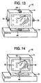
- the video monitor 74 shown in FIGS. 7, 10, and 13 may include any number of commercially available computer monitors, while the video monitors 74 shown in FIGS. 8-9, 11-12, and 14 comprise computer monitors specifically designed to house the various video cameras 76, 78, 82, 84 along the periphery of the monitor 74.
- the video cameras 76, 78, 82, 84 may comprise any number of commercially available cameras capable of generating a video output.
- the video cameras 76, 78 are disposed in a generally vertically co-aligned fashion about the periphery of the display screen of the video monitor 74.
- the CPU (not shown) is capable of forming a composite video image depicting a local conferencee (not shown) looking directly into a camera by seamlessly combining the individual video images obtained by the vertically co-aligned video cameras 76, 78.
- the formation of the composite video image causes the point of view of each video camera 76, 78 to effectively shift inward from its location along the upper and lower periphery of the video monitor 74 toward a predetermined location between the video cameras 76, 78. This inward shifting continues until the point of view of each video camera 76, 78 converges together to form a virtual camera at the predetermined location on the display screen, as shown at 86.
- the video cameras 76, 78 are disposed in a horizontally co-aligned fashion about the periphery of the display screen of the video monitor 74.
- the CPU (not shown) is capable of seamlessly combining the individual video images obtained by the horizontally disposed video cameras 76, 78 to once again form a composite video image depicting a local conferencee (not shown) looking directly into a camera for simulated line-of-sight image capture.
- the formation of the composite video image causes the point of view of each video camera 76, 78 to effectively shift inward from its location along a respective side of the video monitor 74 toward a predetermined location between the video cameras 76, 78.
- the shifting continues until the point of view of each video camera 76, 78 converges together to form a virtual camera at the predetermined location on the display screen, as at 86.
- the first pair of video cameras 76, 78 is generally horizontally co-aligned about either side of the video monitor 74 and a second pair of video cameras 82, 84 is provided in a generally vertically co-aligned fashion about the upper and lower periphery of the video monitor 74.
- the CPU (not shown) is capable of seamlessly combining the individual video images obtained by the video cameras 76, 78, 82, 84 to form a composite video image depicting a local conference (not shown) looking directly into a camera.
- each video camera 76, 78, 82, 84 causes the point of view of each video camera 76, 78, 82, 84 to effectively shift inward from its location along a respective side of the video monitor 74 toward a predetermined location between the video cameras 76, 78, 82, 84.
- the shifting continues until the point of view of each video camera 76, 78, 82, 84 converges together to form a virtual camera at the predetermined location on the display screen, as at 86.
- the composite video image created in the video conferencing system 30 should be formed such that the resulting virtual camera 86 is generally co-aligned with the displayed image of the remote conferencee 36. In this fashion, the local conferencee 36 will appear to be looking directly into the virtual camera 86, which, in turn, results in simulated face-to-face contact between the conferencees 36 for improved interpersonal communication.
- the improved video conferencing system 30 overcomes various deficiencies found in prior art video conferencing systems.
- the video conferencing system 30 provides improved face-to-face contact between conferencees by providing a virtual camera for simulated line-of-sight image capture.
- the conferencing system 30 accomplishes this without reconfiguring the video conferencing stations with additional optical components for modifying the transmission and/or display of remote video images.
- the conferencing system 30 provides the ability to vary the aspect ratio of the video cameras employed in each video conferencing station, thereby allowing the video conferencing system 30 to adapt to a change in the position of the local conferencee without causing distorted and unnatural appearing video images when the local conferencee moves outside the preferred aspect ratio supported by the video camera.
- the video conferencing system 30 also advantageously reduces the degree of parallax or "fish-eye" distortions when the local conferencee is disposed relatively close to the monitor, thereby providing a more naturalistic image of the conferencees for improved interpersonal communication.
- FIGS. 13, 14 are set forth by way of illustration only and are not to be deemed exhaustive as to the scope of the present invention.
- the virtual camera technique of the present invention may find use in any number of computer-based image capture applications where line-of-sight image capture is desired, including but not limited to video conferencing, video postcards, video messaging, multimedia training, and multimedia authoring.
- the term "computer-based” is to be construed broadly as including any of a variety of microprocessor-based systems regardless of the physical housing or structure.
- a computer-based image capture system of the present invention may take the form of a kiosk having an internally disposed processing unit, a display, and at least four image capture devices for capturing images of an operator from at least two pairs of offset locations. It is furthermore to be understood that the image capture devices employed as part of the present invention may comprise four or more image capture devices capable of obtaining photographic and/or video images.
Abstract
Description
- The present invention relates generally to the field of photographic and/or video image capture systems and, more particularly, to an improved image capture system capable of combining the individual images from at least two image capture devices to produce a virtual camera for simulated line-of-sight image capture.
- A fundamental challenge in photographic and/or video image capture is ensuring that the image capture device and subject are properly stationed to provide line-of-sight image capture. As used herein, the term "line-of-sight image capture" means capturing a photographic and/or video image while the subject is looking directly into the lens of the image capture device. Line-of-sight image capture is desirable in that it the resulting photographic and/or video images show the subject looking outward toward a viewer for simulated face-to-face contact. If line-of-sight image capture is not performed, the subject has the appearance of staring off away from the viewer which, as will be appreciated, diminishes the intimacy associated with face-to-face contact.
- Line-of-sight image capture involves two basic operations. First, the image capture device and the subject must be positioned such that the subject is disposed within the field of view of the image capture device. This may be accomplished by adjusting the position of the subject and/or image capture device while monitoring the position of the subject through the use of a viewfinder or preview window. Second, the subject must look directly into the lens of the image capture device during image capture. The end result is a photographic and/or video image which depicts the subject looking directly outward for simulated face-to-face contact with a viewer.
- Line-of-sight image capture is not particularly difficult when endeavoring to capture the photographic and/or video image of another person. An operator can simply view the subject within the viewfinder, adjust the image capture device and/or the positioning of the subject to ensure that the subject is within the viewing angle of the lens, and then instruct the subject to look into the lens before activating the image capture device. Unique challenges exist, however, when the operator of the image capture device is desirous of capturing his or her own photographic and/or video image. For example, in the photographic context, it may be difficult for the operator to ensure that they are properly disposed within the viewing angle of the image capture device. The operator may attempt to take his or her own photographic image by holding a photographic image capture device at arms length and pointing it back at himself or herself. This may be problematic, however, in that the operator is incapable of previewing their own image because the viewfinder is located on the opposite side of the photographic image capture device.
- This problem has been overcome in the video camcorder context with the advent of viewfinders that may be selectively positioned in the same direction as the lens to allow operators to view themselves while capturing their own video image. Notwithstanding this improvement, line-of-sight image capture is nonetheless difficult to perform because the operator must, by definition, look away from the lens of the image capture device in order to preview their image in the viewfinder. If the operator performs image capture while looking at the viewfinder, they will appear to be staring off away from a viewer. If the operator looks back to the lens prior to performing image capture, they run the risk of inadvertently moving the position of the lens such that the resulting images are not centered within the field of view.
- Computer-based image capture systems suffer similar drawbacks in performing line-of-sight image capture. Computer-based image capture systems may include, for example, video conferencing systems, video telephony systems, video messaging systems, video postcard systems, multimedia training systems, and multimedia authoring systems. At a minimum, such systems include a display for visually communicating graphical and/or textual information to an operator, an image capture device for capturing the photographic and/or video image of the operator, and a computer processing unit for coordinating the operation of the overall system. The image capture device is disposed at a predetermined location about the periphery of the display such that the operator has an unobstructed view of the display.
- The main obstacle in performing line-of-sight image capture in such computer-based image capture systems stems from the physical distance or offset between the image capture device and the display. More specifically, line-of-sight image capture in computer-based image capture systems can only be conducted at the expense of viewing the information on the display. This may be seen, for example, with reference to the prior art desktop
video conferencing station 2 shown in FIG. 1. Thevideo conferencing station 2 comprises avideo display 4, an image capture device 6, and apersonal computer 8. The image capture device 6 is disposed on top of thevideo display 4 to ensure that thelocal conferencee 10 has an unobstructed view of the information on thedisplay 4. This necessarily produces a vertical offset between the image capture device 6 and thelocal conferencee 10 such that, when looking at thedisplay 4 as at 12, thelocal conferencee 10 appears to be looking away from the image capture device 6 from the vantage of the remote conferencee. In order to establish face-to-face contact with the remote conferencee, thelocal conferencee 10 must look directly into the lens of the image capture device 6 as at 14. This disadvantageously restricts the local conferencee's 10 ability to view the information displayed on thedisplay 4. - Although described above in the context of a video conferencing system, it is to be understood that this problem exists in every computer-based application where an operator wants to capture his or her own image. These applications may include, but are not necessarily limited to, video conferencing, video telephony, video messaging, video postcard, multimedia training, and multimedia authoring.
- EP-A-5359362 discloses a teleconferencing video system using two cameras symmetrically positioned on opposing sides of an optical axis between an operator and a monitor to produce an image of the operator on the monitor. The two cameras provide from the two images that they observe a virtual image corresponding to the image that would be viewed by a single camera located on the optical axis. US-A-5444478 discloses a method of processing images for constructing a target image from adjacent images having a fixed frame line. This reference relates to joining images of adjacent areas and does not disclose combining images of the same area taken from different viewpoints.
- The present invention is directed at overcoming, or at least reducing the effects of, one or more of the problems set forth above.
- According to a first aspect of this invention there is provided an apparatus as claimed in claim 1 herein.
- According to a second aspect of this invention there is provided a method as claimed in claim 5 herein.
- Other objects and advantages of the invention will become apparent upon reading the following detailed description and upon reference to the drawings in which:
- Figure 1 is a side view of a video conferencing station of the prior art;
- Figure 2 is a flow chart illustrating a method of accomplishing line-of-sight image capture in a computer-based image capture system in accordance with the present invention;
- Figure 3 is a block diagram illustrating the basic functional elements of an improved video conferencing system used in the present invention;
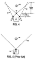
- Figure 4 is an elevational view illustrating the field-of-view for each of a pair of co-aligned video cameras used in the present invention;
- Figure 5 is an elevational view illustrating the field-of-view of a video camera as employed in prior art video conferencing systems;
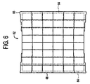
- Figure 6 is a front elevational view illustrating the manner in which a composite video image formed in accordance with the present invention may be stretched from a first state to a second state to remove parallax distortions;
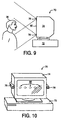
- Figure 7 is a perspective view of a video conferencing station;
- Figure 8 is a perspective view of another video conferencing station;
- Figure 9 is a side view of the video conferencing station shown in FIG. 8;
- Figure 10 is a perspective view of a further video conferencing station;
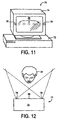
- Figure 11 is a perspective view of yet another video conferencing station;
- Figure 12 is a top view of the video conferencing station shown in FIG 11;
- Figure 13 is a perspective view of a video conferencing station of an embodiment of the present invention; and
- Figure 14 is a perspective view of a video conferencing station of a further embodiment of the present invention.
-
- Illustrative embodiments of the invention are described below. In the interest of clarity, not all features of an actual implementation are described in this specification. It will of course be appreciated that in the development of any such actual embodiment, numerous implementation-specific decisions must be made to achieve the developers' specific goals, such as compliance with system-related and business-related constraints, which will vary from one implementation to another. Moreover, it will be appreciated that such a development effort might be complex and time-consuming, but would nevertheless be a routine undertaking for those of ordinary skill in the art having the benefit of this disclosure.
- With reference to FIG. 2, shown is a flow chart illustrating a method of accomplishing line-of-sight image capture in a computer-based image capture system in accordance with the present invention. The line-of sight image capture method 16 finds particular application in computer-based image capture systems where the operator wants to capture his or her own photographic and/or video image. By way of example, such computer-based image capture systems may include, but are not necessarily limited to, video conferencing systems, video telephony systems, video messaging systems, video postcard systems, multimedia training systems, and multimedia authoring systems.
- The
first step 18 involves capturing a first image of the operator from a first predetermined location about the periphery of the display of the computer-based image capture system. Thesecond step 20 involves capturing a second image of the operator from a second predetermined location about the periphery of the display of the computer-based image capture system. In an important aspect of the present invention, steps 18 and 20 are accomplished by providing at least two image capture devices about the periphery of the display of the computer-based image capture system. Disposing the image capture devices about the periphery of the display is necessary to ensure that the operator has, at all times, an unobstructed view of the visual communication on the display. The image capture insteps - The images captured in
steps step 22 to form a virtual camera at a predetermined location on the display of the computer-based image capture system. By this, it is meant that the individual images obtained insteps -
Step 24 involves displaying the composite image obtained instep 22 on the local display or a remotely located display. Projecting the composite image fromstep 22 onto the local display may be helpful in situations where the operator wishes to preview their own image, such as during video messaging, creating video postcards, multimedia training, and multimedia authoring. Projecting the composite image fromstep 22 onto a remotely located display may be helpful in situations where the operator wishes to transmit their image to a person at a remote location, such as during video conferencing and video telephony. In either case, the operator will appear to be looking directly outward from the composite image for simulated face-to-face contact with a viewer. In a preferred embodiment, the composite image should be projected onto the local or remote display such that it appears in the same approximate position as the virtual camera. Co-aligning the composite image and the virtual camera in this fashion provides simulated line-of-sight image capture without causing the operator to remove his or her eyes from the display to look into an image capture device. - The advantages and benefits of performing line-of-sight image capture in computer-based image capture systems in accordance with the present invention will be discussed below within the context of a video conferencing system. It is to be readily understood that the following embodiments are set forth by way of example only and not limitation. The method of the present invention, once again, may find application in any computer-based image capture system where the operator wants to capture his or her own photographic and/or video image. In addition to a video conferencing system. these computer-based image capture systems may include, but are not necessarily limited to, video telephony systems, video messaging systems, video postcard systems, multimedia training systems, and multimedia authoring systems.
- With reference to FIG. 3, shown is a block diagram of an improved
video conferencing system 30. Broadly stated, the improvedvideo conferencing system 30 includes a plurality of individual video conferencing stations 32 interconnected via acommunication link 34 for facilitating the exchange of audio and video information betweenremote conferencees 36. Each video conferencing station 32 includes acontrol module 38, avideo monitor 40, and at least twovideo cameras video cameras local conferencee 36 from at least two different vantage points. - In one aspect of the present invention, the
control module 38 of each video conferencing station 32 seamlessly combines the video images captured by thelocal video cameras local conferencee 36 appearing to look directly into a camera located on the screen of the local video monitor 40 (a "virtual camera"). Thus, when the composite video image produced by thelocal control module 38 is transferred to the video monitor 40 of a remote video conferencing station 32, the image displayed on the remote video monitor 40 appears to be looking directly at theremote conferencee 36. In this fashion, theconferencees 36 can view their local video monitors 40 while maintaining the outward appearance of looking directly into a camera for effective face-to-face contact between the conferencees 36. - The
control module 38 includes a central processing unit (CPU) 46, avideo graphics card 48, and one or morevideo capture devices CPU 46 manages the overall operation and interaction between thevideo graphics card 48, thevideo capture devices video monitor 40, and thevideo cameras video graphics card 48 facilitates the transmission of video information from theCPU 46 to thevideo monitor 40. The video images obtained by thevideo cameras local CPU 46 via thevideo capture devices CPU 46 is programmed to carry out the operation of seamlessly combining the video images from eachvideo camera local conferencee 36. - The algorithm employed by the
CPU 46 to seamlessly combine the individual images may be based on any of a variety of well known image correlation techniques, such as described in Digital Image Processing, 2nd Edition, William K. Pratt (1991), the entire contents of which is incorporated herein by reference. Generally speaking, image correlation involves conducting a pixel-by-pixel comparison of two video images to determine the spatial differences between the images and thereby correct for any perspective view differences between the individual images. By seamlessly combining. the individual video images in this fashion, theCPU 46 effectively shifts the point of view of eachvideo camera local video monitor 40. This inward shifting continues until the point of view of eachvideo camera local video monitor 40. - This virtual point of view, or virtual camera, is advantageous because it creates the impression that the local conferencee is looking directly into an actual camera. As viewed by a
remote conferencee 36, it appears as though thelocal conferencee 36 is looking directly out of the video monitor 40 for simulated face-to-face contact. By forming the virtual camera on the display of thelocal video monitor 40, thelocal conferencee 36 can continuously view the information on their video monitor 40 without having to look at thevideo cameras remote conferencees 36. - The
video conferencing system 30 may be constructed from any of a variety of commercially available components. For example, the central processing unit (CPU) 46 may comprise any number of processing units capable of high speed parallel operations, such as the PENTIUM®, PENTIUM PRO®, and other processors based on the MMX technology developed by the Intel Corporation. Thevideo graphics card 48 may similarly comprise any number of different commercially available video graphics cards, but in one embodiment is a device controlled interface (DCI) enabled for stretching the composite video image on the video monitor 40 for the purpose of removing parallax distortions. Thevideo capture devices video cameras video capture devices - Although shown as two discrete components, it is to be readily understood that the
video capture devices video cameras communication link 34 may include any of a variety of communication interfaces that meet Internet and telecommunications industry standards (i.e. H. 320, H. 323, H. 324), such as an ISDN interface to a local telephone carrier or a local area network (LAN) interface card to a local area network. Constructing the improvedvideo conferencing system 30 from off-the-shelf components in this fashion advantageously minimizes production cost. - The
video conferencing system 30 is capable of handling both close and long range video conferencing scenarios by providing the ability to selectively modify the aspect ratio of the virtual camera. As shown in FIG. 4, thevideo cameras view conferencee 36. The point where the two fields-of-view intersection point 58 and thevideo cameras CPU 46 is incapable of producing a composite video image in accordance with the present invention when theconferencee 36 is located in this area. All points past theintersection point 58 are referred to as the active zone. In one aspect of the present invention, theCPU 46 is capable of producing a composite video image for simulated face-to-face contact when theconferencee 36 is located at any point in the active zone. TheCPU 46 is therefore capable of generating the virtual camera having any number of aspect ratios depending upon the location of theconferencee 36 or conferencees within the active zone. - In one embodiment, the
intersection point 58 is approximately six inches away from themonitor 40. This advantageously allows thevideo conferencing system 30 of the present invention to provide the virtual camera with an aspect ratio suitable for large portrait capture. The large portrait capture produces a relatively narrow and tall field of view for the resulting virtual camera, which is advantageous in detecting gestural movements on the part of a conferencee disposed in close proximity to thevideo monitor 40, such as during desktop video conferencing. The present invention also has the ability to provide the virtual camera with an aspect ratio suitable for a large landscape capture. The large landscape capture produces a relatively wide and short field of view for the resulting virtual camera, which is advantageous in viewing the participants of a large or spread out group of conferencees, such as during room-based video conferencing. As will be appreciated, the ability to set arbitrary aspect ratios effectively maximizes the versatility of thevideo conferencing system 30 in accommodating both portrait and landscape capture. - The
video conferencing system 30 is also relatively immune to the parallax distortions that plague prior art video conferencing systems. With continued reference to FIG. 4, this immunity to parallax distortions is due to the spaced relation between thevideo cameras video cameras local conferencee 36 may be captured from two separate vantage points. As noted above, theCPU 46 thereafter operates to seamlessly combine the video images from each of thecameras local conferencee 36 looking outwardly for face-to-face contact with the remote conferencee. Due to this image manipulation, theindividual video cameras view local conferencee 36. It is well known that video cameras having narrow projection profiles are capable of obtaining video images that are relatively flat with minimal parallax distortion. - In contrast, the prior
art video camera 14 shown in FIG. 5 does not combine with any other video source and therefore must rely on its own relativelywide projection profile 60 to encompass thelocal conferencee 18. Video cameras having wide projection profiles, however, are known to produce video images having rounded or "fish-eye" parallax distortions that oftentimes causes the video images to appear convoluted and unnatural. In light of the foregoing, the narrow fields-of-view - With reference to FIG. 6, the
video conferencing system 30 also minimizes parallax distortions by implementing a stretching function which makes thecomposite image 62 appear flatter and more naturalistic. The stretching of thecomposite image 62 may be performed under the direction of thevideo graphics card 48 and/or theCPU 46. For purposes of discussion, the stretching function will be explained with reference to thevideo graphics card 48. Thevideo graphics card 48 may comprise any number of commercially available video graphics cards enabled for device controlled interface (DCI) operation. DCI operation allows thevideo graphics card 48 to stretch a relatively small pixel count image to a full screen pixel count image. Thevideo graphics card 48 is thus capable of selectively stretching the composite image from an original state (shown in dotted lines at 64) to an expanded state (shown in solid lines at 66). As can be readily recognized, this image-stretching feature further conditions thecomposite video image 62 of the present invention into a flatter and more natural shape, thereby optimizing the quality of the video communication. - The
video conferencing system 30 can be implemented in both a room-based conferencing arrangement and a desktop conferencing arrangement. Room-based video conferencing systems include at least two remotely located conferencing stations communicatively linked to one another, wherein each conferencing station is designed to accommodate a plurality of conferencees. A room-based conferencing station of the present invention may include several large dedicated TV monitors, at least two image capture devices, a dedicated CPU, a control box, and a dedicated cabinet to house the components. Desktop video conferencing systems also include at least two remotely located conferencing stations communicatively linked to one another, wherein each conferencing station is designed to accommodate a limited number (1 or 2) conferencees. A desktop conferencing station may include a standard computer monitor, at least two image capture devices, and a computer or processor unit for coordinating the transmission and receipt of audio and visual information to and from the various conferencing stations. - For purposes of discussion, the improved
video conferencing system 30 will be described with reference to the various desktop video conferencing stations shown in FIGS. 7-14. The components common to each desktop video conferencing station include apersonal computer 72, aVGA computer monitor 74, and at least one pair ofvideo cameras video monitor 74. Thepersonal computer 72 may comprise any of a variety of commercially available personal computing systems, but should be equipped with a video conferencing hardware and software system for personal computers, such as PROSHARE® manufactured by Intel Corporation. The hardware within the PROSHARE® system includes thecommunication link 34, theCPU 46, thevideo graphics card 48, and thevideo capture devices various video cameras monitor 74. Thevideo cameras - With reference to FIG. 7-9, the
video cameras video monitor 74. The CPU (not shown) is capable of forming a composite video image depicting a local conferencee (not shown) looking directly into a camera by seamlessly combining the individual video images obtained by the verticallyco-aligned video cameras video camera video cameras video camera - With reference to FIG. 10-12, the
video cameras video monitor 74. The CPU (not shown) is capable of seamlessly combining the individual video images obtained by the horizontally disposedvideo cameras video camera video cameras video camera - Preferred embodiments are shown with reference to FIGS. 13 and 14, in which the first pair of
video cameras video monitor 74 and a second pair ofvideo cameras video monitor 74. In this embodiment, the CPU (not shown) is capable of seamlessly combining the individual video images obtained by thevideo cameras video camera video cameras video camera - In one aspect of the present invention, the composite video image created in the
video conferencing system 30 should be formed such that the resultingvirtual camera 86 is generally co-aligned with the displayed image of theremote conferencee 36. In this fashion, thelocal conferencee 36 will appear to be looking directly into thevirtual camera 86, which, in turn, results in simulated face-to-face contact between theconferencees 36 for improved interpersonal communication. - The improved
video conferencing system 30 overcomes various deficiencies found in prior art video conferencing systems. Thevideo conferencing system 30 provides improved face-to-face contact between conferencees by providing a virtual camera for simulated line-of-sight image capture. Theconferencing system 30 accomplishes this without reconfiguring the video conferencing stations with additional optical components for modifying the transmission and/or display of remote video images. Theconferencing system 30 provides the ability to vary the aspect ratio of the video cameras employed in each video conferencing station, thereby allowing thevideo conferencing system 30 to adapt to a change in the position of the local conferencee without causing distorted and unnatural appearing video images when the local conferencee moves outside the preferred aspect ratio supported by the video camera. Thevideo conferencing system 30 also advantageously reduces the degree of parallax or "fish-eye" distortions when the local conferencee is disposed relatively close to the monitor, thereby providing a more naturalistic image of the conferencees for improved interpersonal communication. - It is to be readily understood that the foregoing video conferencing embodiments shown in FIGS. 13, 14 are set forth by way of illustration only and are not to be deemed exhaustive as to the scope of the present invention. The virtual camera technique of the present invention may find use in any number of computer-based image capture applications where line-of-sight image capture is desired, including but not limited to video conferencing, video postcards, video messaging, multimedia training, and multimedia authoring. As used herein, the term "computer-based" is to be construed broadly as including any of a variety of microprocessor-based systems regardless of the physical housing or structure. For example, a computer-based image capture system of the present invention may take the form of a kiosk having an internally disposed processing unit, a display, and at least four image capture devices for capturing images of an operator from at least two pairs of offset locations. It is furthermore to be understood that the image capture devices employed as part of the present invention may comprise four or more image capture devices capable of obtaining photographic and/or video images.
- While the invention is susceptible to various modifications and alternative forms, specific embodiments thereof have been shown by way of example in the drawings and are herein described in detail. It should be understood, however, that the description herein of specific embodiments is not intended to limit the invention to the particular forms disclosed, but on the contrary, the invention is to cover all modifications, equivalents, and alternative falling within the scope of the invention as defined by the appended claims.
Claims (7)
- An apparatus, comprising:a display (74) adapted to display information to an operator (36);image capture means (76-84) disposed proximate to said display (74), said image capture means adapted to capture first, second, third and fourth images of said operator (36) from first, second, third and fourth offset locations, respectively; andimage correlator means (38) adapted to receive said first, second, third and fourth images and to combine said first, second, third and fourth images to form a composite image depicting said operator (36) looking substantially directly into a lens of a virtual image capture device.
- The apparatus as set forth in Claim 1, wherein said image capture means (76-84) includes first, second, third and fourth image capture devices, said first image capture device being adapted to capture images of said operator (36) at said first offset location, said second image capture device being adapted to capture images of said operator (36) at said second offset location, said third image capture device being adapted to capture images of said operator (36) at said third offset location, said fourth image capture device being adapted to capture images of said operator (36) at said fourth offset location .
- The apparatus as set forth in Claim 2, wherein said first image capture device (82) is disposed proximate to a top portion of said display (74), and said second image capture device (84) is disposed proximate to a bottom portion of said display (74).
- The apparatus as set forth in Claim 2, wherein said third image capture device (76) is disposed proximate to a first lateral side of said display (74), and said fourth image capture device (78) is disposed proximate to a second lateral side of said display (74).
- A method of simulating line-of-sight image capture within a computer-based image capture system, comprising the steps of:capturing a first image of an object (36) from a first predetermined offset location;capturing a second image of said object (36) from a second predetermined offset location;capturing a third image of said object (36) from a third predetermined offset location;capturing a fourth image of said object (36) from a fourth predetermined offset location; andcombining said first, second, third and fourth images of said object (36) to form a composite image depicting said object (36)looking directly into a lens of a virtual image capture device.
- A system for facilitating face-to-face communications between conferencees (36) at remote locations, comprising at least two conferencing stations (32) communicatively linked together, each conferencing station (32) including an apparatus as set forth in claim 1 whereby the operator is one of the conferencees and the virtual image capture device is a virtual camera (86) at a predetermined location on said display means (40) for simulating face-to-face communication between conferencees (36) at remote video conferencing locations.
- The system as set forth in claim 6, wherein said first, second, third and fourth offset locations are above, below, left and right, respectively, of said display means (40).
Applications Claiming Priority (3)
| Application Number | Priority Date | Filing Date | Title |
|---|---|---|---|
| US08/993,323 US6259470B1 (en) | 1997-12-18 | 1997-12-18 | Image capture system having virtual camera |
| US993323 | 1997-12-18 | ||
| PCT/US1998/027024 WO1999031889A1 (en) | 1997-12-18 | 1998-12-17 | Improved image capture system having virtual camera |
Publications (3)
| Publication Number | Publication Date |
|---|---|
| EP1038405A1 EP1038405A1 (en) | 2000-09-27 |
| EP1038405A4 EP1038405A4 (en) | 2001-04-18 |
| EP1038405B1 true EP1038405B1 (en) | 2003-11-26 |
Family
ID=25539385
Family Applications (1)
| Application Number | Title | Priority Date | Filing Date |
|---|---|---|---|
| EP98964110A Expired - Lifetime EP1038405B1 (en) | 1997-12-18 | 1998-12-17 | Improved image capture system having virtual camera |
Country Status (6)
| Country | Link |
|---|---|
| US (1) | US6259470B1 (en) |
| EP (1) | EP1038405B1 (en) |
| JP (1) | JP4057241B2 (en) |
| AU (1) | AU1930399A (en) |
| DE (1) | DE69820112T2 (en) |
| WO (1) | WO1999031889A1 (en) |
Cited By (1)
| Publication number | Priority date | Publication date | Assignee | Title |
|---|---|---|---|---|
| EP4329291A1 (en) * | 2022-08-26 | 2024-02-28 | Telefónica Germany GmbH & Co. OHG | System, method, computer program and computer-readable medium |
Families Citing this family (48)
| Publication number | Priority date | Publication date | Assignee | Title |
|---|---|---|---|---|
| JP3145059B2 (en) * | 1997-06-13 | 2001-03-12 | 株式会社ナムコ | Information storage medium and image generation device |
| US6259470B1 (en) | 1997-12-18 | 2001-07-10 | Intel Corporation | Image capture system having virtual camera |
| US6208373B1 (en) * | 1999-08-02 | 2001-03-27 | Timothy Lo Fong | Method and apparatus for enabling a videoconferencing participant to appear focused on camera to corresponding users |
| US7015954B1 (en) * | 1999-08-09 | 2006-03-21 | Fuji Xerox Co., Ltd. | Automatic video system using multiple cameras |
| US6864912B1 (en) * | 1999-12-16 | 2005-03-08 | International Business Machines Corp. | Computer system providing hands free user input via optical means for navigation or zooming |
| US6361173B1 (en) * | 2001-02-16 | 2002-03-26 | Imatte, Inc. | Method and apparatus for inhibiting projection of selected areas of a projected image |
| US20020131643A1 (en) * | 2001-03-13 | 2002-09-19 | Fels Sol Sidney | Local positioning system |
| US6798457B2 (en) | 2001-09-26 | 2004-09-28 | Digeo, Inc. | Camera positioning system and method for eye-to-eye communication |
| US6943843B2 (en) * | 2001-09-27 | 2005-09-13 | Digeo, Inc. | Camera positioning system and method for eye-to eye communication |
| US20040207718A1 (en) * | 2001-11-14 | 2004-10-21 | Boyden James H. | Camera positioning system and method for eye -to-eye communication |
| US20030112325A1 (en) * | 2001-12-13 | 2003-06-19 | Digeo, Inc. | Camera positioning system and method for eye-to-eye communication |
| JP2004048644A (en) * | 2002-05-21 | 2004-02-12 | Sony Corp | Information processor, information processing system and interlocutor display method |
| US6853398B2 (en) * | 2002-06-21 | 2005-02-08 | Hewlett-Packard Development Company, L.P. | Method and system for real-time video communication within a virtual environment |
| US7307654B2 (en) * | 2002-10-31 | 2007-12-11 | Hewlett-Packard Development Company, L.P. | Image capture and viewing system and method for generating a synthesized image |
| US7057662B2 (en) * | 2002-11-22 | 2006-06-06 | Hewlett-Packard Development Company, L.P. | Retractable camera apparatus |
| US20040205256A1 (en) * | 2002-11-27 | 2004-10-14 | Richard Hoffman | System and method for communicating between two or more locations |
| JP3849654B2 (en) * | 2003-02-21 | 2006-11-22 | 株式会社日立製作所 | Projection display |
| US8299979B2 (en) * | 2003-05-14 | 2012-10-30 | Broadcom Corporation | Integral eye-path alignment on telephony and computer video devices using two or more image sensing devices |
| JP2004350206A (en) * | 2003-05-26 | 2004-12-09 | Sharp Corp | Imaging apparatus |
| JP4103848B2 (en) * | 2004-03-19 | 2008-06-18 | ソニー株式会社 | Information processing apparatus and method, recording medium, program, and display apparatus |
| JP4417386B2 (en) * | 2004-09-15 | 2010-02-17 | パイオニア株式会社 | Video display system and video display method |
| US8854486B2 (en) | 2004-12-17 | 2014-10-07 | Mitsubishi Electric Research Laboratories, Inc. | Method and system for processing multiview videos for view synthesis using skip and direct modes |
| US7728878B2 (en) * | 2004-12-17 | 2010-06-01 | Mitsubishi Electric Research Labortories, Inc. | Method and system for processing multiview videos for view synthesis using side information |
| CN100375070C (en) * | 2004-12-31 | 2008-03-12 | 联想(北京)有限公司 | Video frequency data acquisition method employing mobile phone with camera as computer camera |
| DE112006001864T5 (en) * | 2005-07-14 | 2008-06-05 | GM Global Technology Operations, Inc., Detroit | System for monitoring the vehicle environment from a remote perspective |
| US20070109410A1 (en) * | 2005-11-15 | 2007-05-17 | Creative Technology Ltd. | Apparatus for audio reproduction and image capturing |
| JP2008140271A (en) * | 2006-12-04 | 2008-06-19 | Toshiba Corp | Interactive device and method thereof |
| EP2143270A1 (en) | 2007-03-30 | 2010-01-13 | Nxp B.V. | A device for and a method of processing image data representative of an object |
| US8031222B2 (en) * | 2007-04-25 | 2011-10-04 | Microsoft Corporation | Multiple resolution capture in real time communications |
| US8823769B2 (en) | 2011-01-05 | 2014-09-02 | Ricoh Company, Ltd. | Three-dimensional video conferencing system with eye contact |
| CN102299410A (en) * | 2011-05-10 | 2011-12-28 | 圆刚科技股份有限公司 | Digital TV (television) antenna |
| US9723205B2 (en) * | 2012-06-20 | 2017-08-01 | Nokia Technologies Oy | Display camera operation |
| US20140320592A1 (en) * | 2013-04-30 | 2014-10-30 | Microsoft Corporation | Virtual Video Camera |
| JP6100089B2 (en) * | 2013-05-17 | 2017-03-22 | キヤノン株式会社 | Image processing apparatus, image processing method, and program |
| US9363476B2 (en) * | 2013-09-20 | 2016-06-07 | Microsoft Technology Licensing, Llc | Configuration of a touch screen display with conferencing |
| US20150085060A1 (en) | 2013-09-20 | 2015-03-26 | Microsoft Corporation | User experience for conferencing with a touch screen display |
| JP2015164789A (en) * | 2014-03-03 | 2015-09-17 | キヤノン株式会社 | Electronic apparatus |
| US9541998B2 (en) | 2015-01-29 | 2017-01-10 | Samsung Electronics Co., Ltd. | Electronic system with gaze alignment mechanism and method of operation thereof |
| US10701318B2 (en) | 2015-08-14 | 2020-06-30 | Pcms Holdings, Inc. | System and method for augmented reality multi-view telepresence |
| KR101782582B1 (en) * | 2015-12-04 | 2017-09-28 | 카페24 주식회사 | Method, Apparatus and System for Transmitting Video Based on Eye Tracking |
| WO2017172528A1 (en) | 2016-04-01 | 2017-10-05 | Pcms Holdings, Inc. | Apparatus and method for supporting interactive augmented reality functionalities |
| US10721419B2 (en) * | 2017-11-30 | 2020-07-21 | International Business Machines Corporation | Ortho-selfie distortion correction using multiple image sensors to synthesize a virtual image |
| US11089265B2 (en) | 2018-04-17 | 2021-08-10 | Microsoft Technology Licensing, Llc | Telepresence devices operation methods |
| US11064154B2 (en) * | 2019-07-18 | 2021-07-13 | Microsoft Technology Licensing, Llc | Device pose detection and pose-related image capture and processing for light field based telepresence communications |
| US11553123B2 (en) | 2019-07-18 | 2023-01-10 | Microsoft Technology Licensing, Llc | Dynamic detection and correction of light field camera array miscalibration |
| US11270464B2 (en) | 2019-07-18 | 2022-03-08 | Microsoft Technology Licensing, Llc | Dynamic detection and correction of light field camera array miscalibration |
| US11082659B2 (en) | 2019-07-18 | 2021-08-03 | Microsoft Technology Licensing, Llc | Light field camera modules and light field camera module arrays |
| US11336833B1 (en) * | 2021-02-26 | 2022-05-17 | Microsoft Technology Licensing, Llc | Remote user field of view-based camera orienting |
Family Cites Families (23)
| Publication number | Priority date | Publication date | Assignee | Title |
|---|---|---|---|---|
| GB8827952D0 (en) * | 1988-11-30 | 1989-01-05 | Screen Form Inc | Display device |
| US5214519A (en) * | 1991-04-29 | 1993-05-25 | E. I. Du Pont De Nemours And Company | Method and apparatus for producing a specified format output image from an arbitrary format source image |
| JP3034659B2 (en) * | 1991-09-26 | 2000-04-17 | 株式会社日立製作所 | Enlarged screen display circuit and horizontal filter circuit used therefor |
| KR940017747A (en) * | 1992-12-29 | 1994-07-27 | 에프. 제이. 스미트 | Image processing device |
| US5359362A (en) * | 1993-03-30 | 1994-10-25 | Nec Usa, Inc. | Videoconference system using a virtual camera image |
| US5450140A (en) * | 1993-04-21 | 1995-09-12 | Washino; Kinya | Personal-computer-based video production system |
| JPH07154763A (en) * | 1993-11-26 | 1995-06-16 | Fujitsu Ltd | Desk-side video conference system |
| JPH07245696A (en) * | 1994-03-04 | 1995-09-19 | Minolta Co Ltd | Image forming device |
| CA2126142A1 (en) | 1994-06-17 | 1995-12-18 | David Alexander Kahn | Visual communications apparatus |
| US5666155A (en) * | 1994-06-24 | 1997-09-09 | Lucent Technologies Inc. | Eye contact video telephony |
| US5572248A (en) * | 1994-09-19 | 1996-11-05 | Teleport Corporation | Teleconferencing method and system for providing face-to-face, non-animated teleconference environment |
| US5500671A (en) * | 1994-10-25 | 1996-03-19 | At&T Corp. | Video conference system and method of providing parallax correction and a sense of presence |
| JP2891127B2 (en) * | 1994-12-28 | 1999-05-17 | ティアック株式会社 | Disk unit |
| US5815197A (en) * | 1995-02-16 | 1998-09-29 | Sumitomo Electric Industries, Ltd. | Two-way interactive system, terminal equipment and image pickup apparatus having mechanism for matching lines of sight between interlocutors through transmission means |
| US5729471A (en) | 1995-03-31 | 1998-03-17 | The Regents Of The University Of California | Machine dynamic selection of one video camera/image of a scene from multiple video cameras/images of the scene in accordance with a particular perspective on the scene, an object in the scene, or an event in the scene |
| WO1996031843A1 (en) * | 1995-04-07 | 1996-10-10 | Advanced Micro Devices, Inc. | Method and apparatus for image rotation |
| US5612734A (en) * | 1995-11-13 | 1997-03-18 | Bell Communications Research, Inc. | Eye contact apparatus employing a directionally transmissive layer for video conferencing |
| US5757424A (en) * | 1995-12-19 | 1998-05-26 | Xerox Corporation | High-resolution video conferencing system |
| US5675376A (en) * | 1995-12-21 | 1997-10-07 | Lucent Technologies Inc. | Method for achieving eye-to-eye contact in a video-conferencing system |
| JP3880088B2 (en) * | 1995-12-28 | 2007-02-14 | キヤノン株式会社 | Encoding device and decoding device |
| JPH1079866A (en) * | 1996-09-04 | 1998-03-24 | Canon Inc | Image processing unit and method |
| US5781229A (en) | 1997-02-18 | 1998-07-14 | Mcdonnell Douglas Corporation | Multi-viewer three dimensional (3-D) virtual display system and operating method therefor |
| US6259470B1 (en) | 1997-12-18 | 2001-07-10 | Intel Corporation | Image capture system having virtual camera |
-
1997
- 1997-12-18 US US08/993,323 patent/US6259470B1/en not_active Expired - Lifetime
-
1998
- 1998-12-17 WO PCT/US1998/027024 patent/WO1999031889A1/en active IP Right Grant
- 1998-12-17 DE DE69820112T patent/DE69820112T2/en not_active Expired - Lifetime
- 1998-12-17 EP EP98964110A patent/EP1038405B1/en not_active Expired - Lifetime
- 1998-12-17 JP JP2000539643A patent/JP4057241B2/en not_active Expired - Lifetime
- 1998-12-17 AU AU19303/99A patent/AU1930399A/en not_active Abandoned
Cited By (1)
| Publication number | Priority date | Publication date | Assignee | Title |
|---|---|---|---|---|
| EP4329291A1 (en) * | 2022-08-26 | 2024-02-28 | Telefónica Germany GmbH & Co. OHG | System, method, computer program and computer-readable medium |
Also Published As
| Publication number | Publication date |
|---|---|
| AU1930399A (en) | 1999-07-05 |
| DE69820112T2 (en) | 2004-04-15 |
| WO1999031889A1 (en) | 1999-06-24 |
| US6259470B1 (en) | 2001-07-10 |
| EP1038405A4 (en) | 2001-04-18 |
| DE69820112D1 (en) | 2004-01-08 |
| EP1038405A1 (en) | 2000-09-27 |
| JP2002509399A (en) | 2002-03-26 |
| JP4057241B2 (en) | 2008-03-05 |
Similar Documents
| Publication | Publication Date | Title |
|---|---|---|
| EP1038405B1 (en) | Improved image capture system having virtual camera | |
| US8467510B2 (en) | Method and apparatus maintaining eye contact in video delivery systems using view morphing | |
| US8890922B2 (en) | Video communication method, device and system | |
| US7710463B2 (en) | Method and system for compensating for parallax in multiple camera systems | |
| US7911513B2 (en) | Simulating short depth of field to maximize privacy in videotelephony | |
| US7643064B1 (en) | Predictive video device system | |
| US6753900B2 (en) | Method and apparatus for overcoming the limitations of camera angle in video conferencing applications | |
| KR101598069B1 (en) | System and method for eye alignment in video | |
| GB2440376A (en) | Wide angle video conference imaging | |
| Giger et al. | Gaze correction with a single webcam | |
| US10484579B2 (en) | Systems and methods to overlay remote and local video feeds | |
| US9466148B2 (en) | Systems and methods to dynamically adjust an image on a display monitor represented in a video feed | |
| JPH0522722A (en) | Input/ouptup equipment for image communication | |
| CN108632563A (en) | Dynamic visual telephone system and its application method | |
| CN112601044A (en) | Conference scene picture self-adaption method | |
| CN107659786A (en) | A kind of panoramic video monitoring device and processing method | |
| JP2005142765A (en) | Apparatus and method for imaging | |
| EP2355499A1 (en) | Video conferencing method, a related system, a related client device and a related network element | |
| JPH0481088A (en) | Coincident glance type figure picture display image pickup device | |
| CN213937995U (en) | Electronic equipment with two leading camera lenses | |
| JP4166463B2 (en) | Video generation device | |
| CN112887655B (en) | Information processing method and information processing device | |
| JP2004159061A (en) | Image display device with image pickup function | |
| Yamada et al. | High-quality stereo panorama generation using a three-camera system | |
| CN112738309A (en) | Electronic equipment with double front lenses and shooting method |
Legal Events
| Date | Code | Title | Description |
|---|---|---|---|
| PUAI | Public reference made under article 153(3) epc to a published international application that has entered the european phase |
Free format text: ORIGINAL CODE: 0009012 |
|
| 17P | Request for examination filed |
Effective date: 20000619 |
|
| AK | Designated contracting states |
Kind code of ref document: A1 Designated state(s): DE FR GB IT |
|
| A4 | Supplementary search report drawn up and despatched |
Effective date: 20010307 |
|
| AK | Designated contracting states |
Kind code of ref document: A4 Designated state(s): DE FR GB IT |
|
| RIC1 | Information provided on ipc code assigned before grant |
Free format text: 7H 04N 13/04 A, 7G 06T 7/00 B |
|
| 17Q | First examination report despatched |
Effective date: 20021112 |
|
| GRAH | Despatch of communication of intention to grant a patent |
Free format text: ORIGINAL CODE: EPIDOS IGRA |
|
| GRAS | Grant fee paid |
Free format text: ORIGINAL CODE: EPIDOSNIGR3 |
|
| GRAA | (expected) grant |
Free format text: ORIGINAL CODE: 0009210 |
|
| AK | Designated contracting states |
Kind code of ref document: B1 Designated state(s): DE FR GB IT |
|
| PG25 | Lapsed in a contracting state [announced via postgrant information from national office to epo] |
Ref country code: IT Free format text: LAPSE BECAUSE OF FAILURE TO SUBMIT A TRANSLATION OF THE DESCRIPTION OR TO PAY THE FEE WITHIN THE PRE;WARNING: LAPSES OF ITALIAN PATENTS WITH EFFECTIVE DATE BEFORE 2007 MAY HAVE OCCURRED AT ANY TIME BEFORE 2007. THE CORRECT EFFECTIVE DATE MAY BE DIFFERENT FROM THE ONE RECORDED.SCRIBED TIME-LIMIT Effective date: 20031126 |
|
| REG | Reference to a national code |
Ref country code: GB Ref legal event code: FG4D |
|
| REF | Corresponds to: |
Ref document number: 69820112 Country of ref document: DE Date of ref document: 20040108 Kind code of ref document: P |
|
| ET | Fr: translation filed | ||
| PLBE | No opposition filed within time limit |
Free format text: ORIGINAL CODE: 0009261 |
|
| STAA | Information on the status of an ep patent application or granted ep patent |
Free format text: STATUS: NO OPPOSITION FILED WITHIN TIME LIMIT |
|
| 26N | No opposition filed |
Effective date: 20040827 |
|
| PGFP | Annual fee paid to national office [announced via postgrant information from national office to epo] |
Ref country code: FR Payment date: 20100106 Year of fee payment: 12 |
|
| PGFP | Annual fee paid to national office [announced via postgrant information from national office to epo] |
Ref country code: DE Payment date: 20091230 Year of fee payment: 12 |
|
| REG | Reference to a national code |
Ref country code: FR Ref legal event code: ST Effective date: 20110831 |
|
| PG25 | Lapsed in a contracting state [announced via postgrant information from national office to epo] |
Ref country code: FR Free format text: LAPSE BECAUSE OF NON-PAYMENT OF DUE FEES Effective date: 20110103 |
|
| REG | Reference to a national code |
Ref country code: DE Ref legal event code: R119 Ref document number: 69820112 Country of ref document: DE Effective date: 20110701 |
|
| PG25 | Lapsed in a contracting state [announced via postgrant information from national office to epo] |
Ref country code: DE Free format text: LAPSE BECAUSE OF NON-PAYMENT OF DUE FEES Effective date: 20110701 |
|
| PGFP | Annual fee paid to national office [announced via postgrant information from national office to epo] |
Ref country code: GB Payment date: 20161214 Year of fee payment: 19 |
|
| GBPC | Gb: european patent ceased through non-payment of renewal fee |
Effective date: 20171217 |
|
| PG25 | Lapsed in a contracting state [announced via postgrant information from national office to epo] |
Ref country code: GB Free format text: LAPSE BECAUSE OF NON-PAYMENT OF DUE FEES Effective date: 20171217 |