EP1035663A2 - Two-way communication system for mobile users using a satellite system - Google Patents
Two-way communication system for mobile users using a satellite system Download PDFInfo
- Publication number
- EP1035663A2 EP1035663A2 EP00107683A EP00107683A EP1035663A2 EP 1035663 A2 EP1035663 A2 EP 1035663A2 EP 00107683 A EP00107683 A EP 00107683A EP 00107683 A EP00107683 A EP 00107683A EP 1035663 A2 EP1035663 A2 EP 1035663A2
- Authority
- EP
- European Patent Office
- Prior art keywords
- satellite
- satellites
- frequency
- radio
- constellation
- Prior art date
- Legal status (The legal status is an assumption and is not a legal conclusion. Google has not performed a legal analysis and makes no representation as to the accuracy of the status listed.)
- Withdrawn
Links
Images


Classifications
-
- H—ELECTRICITY
- H04—ELECTRIC COMMUNICATION TECHNIQUE
- H04B—TRANSMISSION
- H04B7/00—Radio transmission systems, i.e. using radiation field
- H04B7/14—Relay systems
- H04B7/15—Active relay systems
- H04B7/185—Space-based or airborne stations; Stations for satellite systems
- H04B7/1851—Systems using a satellite or space-based relay
- H04B7/18513—Transmission in a satellite or space-based system
-
- H—ELECTRICITY
- H04—ELECTRIC COMMUNICATION TECHNIQUE
- H04B—TRANSMISSION
- H04B7/00—Radio transmission systems, i.e. using radiation field
- H04B7/14—Relay systems
- H04B7/15—Active relay systems
- H04B7/185—Space-based or airborne stations; Stations for satellite systems
- H04B7/195—Non-synchronous stations
-
- Y—GENERAL TAGGING OF NEW TECHNOLOGICAL DEVELOPMENTS; GENERAL TAGGING OF CROSS-SECTIONAL TECHNOLOGIES SPANNING OVER SEVERAL SECTIONS OF THE IPC; TECHNICAL SUBJECTS COVERED BY FORMER USPC CROSS-REFERENCE ART COLLECTIONS [XRACs] AND DIGESTS
- Y02—TECHNOLOGIES OR APPLICATIONS FOR MITIGATION OR ADAPTATION AGAINST CLIMATE CHANGE
- Y02D—CLIMATE CHANGE MITIGATION TECHNOLOGIES IN INFORMATION AND COMMUNICATION TECHNOLOGIES [ICT], I.E. INFORMATION AND COMMUNICATION TECHNOLOGIES AIMING AT THE REDUCTION OF THEIR OWN ENERGY USE
- Y02D30/00—Reducing energy consumption in communication networks
- Y02D30/70—Reducing energy consumption in communication networks in wireless communication networks
Definitions
- the present invention relates to the field of satellite communications and telecommunications systems. More particularly, this invention provides methods of frequency sharing for non-geostationary, store-and-forward, satellite communication systems.
- wireless communications have undergone a rapid increase in subscriber growth in the past several years.
- the result is that new enhanced wireless services tend to gain market acceptance more rapidly than did earlier wireless technologies.
- This phenomenon is attributable to the increasing functionality, value relative to price, and awareness among the population of each successive technology.
- Paging was introduced with only one-way, non-voice communications at a relatively high price.
- SMR provided two-way communications, but only within a closed user-group.
- cellular offered two-way interconnected voice with increasingly wide area coverage. The result of the rapid growth in wireless services worldwide builds an awareness and future demand for the benefits of advanced wireless communications.
- Mobile satellite services are uniquely positioned to complete the evolution of wireless services. These services offer ubiquitous coverage, interconnection with other networks and a variety of services.
- Mobile satellites will be able to support both voice and data terminals, depending upon the particular need of the user.
- voice service will be expensive relative to data, due to the greater infrastructure required for voice communications and the generally greater efficiency of data communications.
- Robert R. Newton discloses a Multipurpose Satellite System in his U.S. Patent No. 3,497,807. Newton describes a system in which "any point on Earth is always within the line of sight of some satellite and any satellite is always within line of sight of an adjacent satellite in the same orbital plane.” Col. 2, Lines 4-7.
- U.S. Patent No. 4,135,156 by Sanders et al. entitled Satellite Communications System Incorporating Ground Relay Station Through Which Messages Between Terminal Stations Are Routed, contains a description of a "satellite relay communications system" that "includes a ground relay station arranged so that each message from one subscriber to another is relayed by the satellite relay to the ground relay, processed by the ground relay and then transmitted to the second subscriber by way of the satellite relay.” See Sanders et al., Abstract, Lines 1-6.
- the references cited above disclose telecommunication systems that include satellites deployed in polar, Equatorial and inclined low Earth orbits (LEO).
- LEO polar, Equatorial and inclined low Earth orbits
- the systems provide for transmitting a message between two low-power fixed or mobile terminals on the ground through a store-and-forward network.
- the store-and-forward relay method takes advantage of the geometry of a system which allows the satellites to fly over different parts of the globe frequently.
- These LEO systems do not provide access to a satellite one hundred per cent of the time. In the most populated areas of the globe, a user may have to wait for many minutes until a satellite flies into view.
- the U.S. Federal Communications System (FCC) and the International Telecommunications Union (ITU) have historically based assigned frequency spectrum to non-geostationary satellites on an exclusive use basis. That is, once assigned to a system, the frequency spectrum is unavailable for assignment to others wishing to operate in the same service region. In some cases, assignment of frequency spectrum to a system comprising a single satellite would preclude further use of that spectrum world wide.
- FCC Federal Communications System
- ITU International Telecommunications Union
- the current invention provides new methods for frequency spectrum sharing among satellites of a new constellation and satellites of an already existing constellation of non-geostationary satellites. For such satellites, potential radio frequency interference occurs at varying, but predictable times when satellite radio beams overlap on the Earth or satellites otherwise have conflicting regions of their coverage footprints. Two constellations of non-geostationary satellites have potentially interfering, overlapping coverage in many regions of the Earth simultaneously.
- a new constellation of satellites can share frequency spectrum with several existing constellations which currently operate in mutually-exclusive frequency spectra. This is possible with a minimum of complexity and no impact to the existing constellation. Provision of a schedule of frequency use and orbital element data for the existing satellites is required. Sharing among more constellations provides additional frequency spectrum to allocate to satellites having potential conflicts. Therefore, the simultaneous coverage conjunction (areas where one or more satellites must be "turned off" to prevent frequency interference) of satellites of all constellations becomes smaller.
- One of the embodiments of the present invention supports a novel satellite, non-voice, non-geosynchronous communication system that includes a constellation of forty-eight satellites equally deployed in four pairs of low Earth orbits. These orbits are inclined at 50 degrees to the Equator.
- the satellites orbit in approximately orthogonal planes. A satellite leaves the Equator in one plane on an ascending node while a satellite in the orthogonal plane leaves the Equator on a descending node.
- the present invention is not limited to such a constellation and is equally applicable to larger or smaller constellations. It is applicable to satellites in polar, inclined, or Equatorial orbits and circular, elliptical with varying foci, or highly elliptical orbits such as the Molnya orbit.
- the invention is independent of the type of communication service offered.
- the invention may be employed whenever the radio beams of one satellite in a constellation overlap those of another satellite in the same or in a different constellation. While this invention may be used for interference protection by satellites in geosynchronous (including geostationary) orbits, it is primarily concerned with preventing radio frequency interference (RFI) by new constellations of satellites in non-geosynchronous orbits with satellites in existing constellations.
- RFID radio frequency interference
- a preferred method of communication provides a system for transmitting a message between two terminals on the ground through a store-and-forward network.
- communication may be virtually instantaneous unless there are interfering signals from other satellites in different services which could block or cause retransmission of the message.
- the present invention will allow two or more satellite systems to utilize the same band of radio frequencies for communication between ground stations and satellites. This is accomplished by timing transmissions of each satellite in one constellation on one frequency or sets of frequencies so the transmissions visible at a point on the Earth do not occur simultaneously with transmissions by a satellite in a second constellation visible at the same point on the Earth on the same frequencies.
- a first satellite constellation, newly launched, will be referred to as “System A” and a second, existing satellite constellation will be referred to as “System B.”
- System A a first satellite constellation
- System B a second, existing satellite constellation
- Newly launched System A must not interfere with existing System B.
- a System A satellite is required to change frequency to avoid interference with a System B satellite.
- the System A satellite must not use a frequency already in use by a second System A satellite which overlaps the first satellite's coverage.
- the System A first satellite must operate on a frequency assigned to a System A third orbital plane satellite that also does not overlap at the time.
- such a choice is generally available in LEO constellations so that required frequency changes do not ripple trough the constellation.
- Radio frequencies of System A satellites are allocated so that overlapping visibility contours are not assigned the same frequency.
- “Visible” refers to the fact that transmissions on very high frequency (VHF) or ultra high frequency (UHF) are essentially line of sight.
- Timing of transmissions by a satellite residing in System A is determined with reference to calculations of the ground visibility contours (radio beam footprints) of all of the satellites in System A and in those of satellites residing in System B and others if necessary.
- a search algorithm as used to determine the choice of time and frequency in an automated fashion and scheduled days in advance.
- An ephemeris data set is constructed including orbital parameter data of all of the satellites in System A and System B.
- the orbital parameter data includes a continuous description of the position of the radio beam footprints wish time for each satellite. It also may include the operating radio frequencies assigned for each satellite in System B.
- a radio frequency use schedule is then constructed using a radio frequency use schedule algorithm in a conventional central processing unit (CPU).
- the algorithm is used to implement a frequency avoidance plan.
- the algorithm determines mutual visibility of a System A satellites and a System B satellites by a terminal on the Earth by calculating the distance between satellites based on the orbital data ephemeris.
- the algorithm determines which satellite in the System B is impacted by a satellite in System A. Only a satellite in System A which impacts another satellite is required to change frequency.
- the radio frequency use schedule is frequently updated to correct for satellite drift and other changes in satellite constellation topology.
- the radio frequency use schedule is periodically communicated by a ground relay station-to-satellite uplink to each satellite in System A where it is stored on board. Each satellite is then operated in accordance with the radio frequency use schedule. Frequency changes are made to avoid interfering with other satellites in the System A or System B.
- a preferred radio frequency use schedule algorithm that minimizes (or prohibits) System A satellites from causing interference to System B satellites also minimizes the system outages of System A.
- System A outages can be caused at times when no unused frequencies are available. Different frequencies are assigned to System A satellites in each orbit plane. Frequencies at the low end and high end of the frequency bands are interleaved to minimize the number of satellites that must change frequency for any overlapping footprint conflict. Any required frequency change is made by changing to the frequency assignment of a satellite in the System A constellation to a frequency assigned to satellites in an "orthogonal" orbit plane. If such a frequency is unavailable, then any available frequency is chosen.
- the frequency assignments to each of the eight orbital planes of System A are interleaved such that every odd numbered orbit plane 1, 3, 5, 7 is assigned a frequency from a first half of the frequency spectrum and every even numbered orbit plane 2, 4, 6 and 8 is assigned a frequency from the opposite half of the spectrum. So, for example, if the Space-to-Earth spectrum ranges from 137.000 MHz to 138.000 MHz, then the odd numbered orbital planes are assigned a frequency in the band between 137.000 MHz and 137.500 MHz and the even numbered orbital planes are assigned a frequency in the band between 137.500 MHz and 138.000 MHz.
- the order of frequency assignment and portion of the band assigned to odd or even numbered planes may be reversed.
- the frequency used in the paired, orthogonal plane, if available is adopted by that satellite. If the selected frequency is not available then any available frequency may be used.
- the invention is not limited by the number of orbital planes comprising System B.
- the method described above is used with packet transmission store and forward protocols so that infrequent interference between satellites in the System A can be tolerated due to minimal degradation caused by burst packet transmissions and packet re-transmissions.
- timing of the transmissions and frequency assignments is based on a satellite in System A detecting the use of a frequency by a satellite in System B and relaying that information between satellites in System A. Avoiding transmission on the same frequency by the two constellations requires all satellites in System A to detect transmissions in their field of view and change their transmitting frequency to a non-interfering frequency based on the frequency use information relayed between satellites in System A.
- the radio frequency reuse schedule is computed on board each satellite based on the know position and frequencies of other satellites which is periodically furnished from a ground station.
- FIG. 1 is a schematic view of a constellation 10 of forty-eight satellites (A ) operating in four conjugate pairs of orbits 22 supported by a preferred embodiment of the present invention. For the sake of clarity, only two conjugate pairs of orbits 22 are shown.
- the term “constellation” refers to the entire group of satellites.
- a complete implementation of the invention which incorporates the constellation 10 as well as equipment such as relay stations 18 or user terminals 20 on or near the surface of the Earth E is described by the term "system.”
- a first satellite constellation 10, newly launched will be referred to as "System A” and a second, existing satellite constellation will be referred to as "System B.”
- the satellites 12 shown in Figure 1 operate in one preferred embodiment, in a circular orbit 14, 15 about the Earth E, which is inclined at 50 degrees to the Earth's Equator 16.
- the satellites (A ) are equally spaced in orthogonal pairs of orbits 22 at an altitude of 950 km.
- the pairs of orbits 22 are positioned so that die ascending node of one orbit 14 is displaced 180 degrees in right ascension (longitude) from the ascending node of the orthogonal, conjugate orbit 15.
- the ascending node of one orbit 14 must therefore occur at the same angle of right ascension as does the descending node of the orthogonal, conjugate orbit 15.
- Ascending nodes of adjacent orbital planes are placed at 0, 45, 90, 135, 180, 225, 270 and 315 degrees right ascension.
- the interplane phase angle between any two adjacent orbital planes in one embodiment is zero degrees. In another embodiment, the interplane phase angle is 7.5 degrees.
- the interplane phase angle is the angle between two satellites A , A in adjacent planes when one satellite is at the Equator 16.
- the relay stations 18 are located on the ground and distributed internationally in a pattern of locations on the Earth which maximize coverage and minimize time to forward messages and data between any two user terminals. In a preferred embodiment of the System A, there are approximately ten to one hundred "distributed" relay stations 18.
- the relay stations 18 are capable of communicating with the satellites A in orbit via uplinks and downlinks.
- the relay stations 18 may be connected to terrestrial based networks such as public telephone networks.
- User terminals 20 are randomly distributed over the Earth's surface and are also capable of communicating with the satellites A .
- the user terminals 20 may be fixed, mobile or portable. They may be located on land, at sea or in the air.
- While this invention may be used for interference protection by satellites in geosynchronous (including geostationary) orbits, it is primarily concerned with preventing radio frequency interference (RFI) by new constellations of satellites A in non-geosynchronous orbits with satellites B in existing systems.
- RFI radio frequency interference
- the attitude of the satellites may be other than 950 km so long as it is greater than 100 km and substantially less than geostationary altitude.
- the altitudes of satellites in differing orbits may be different.
- the inclination of the orbit planes 14, 15 may vary from 0 degrees to 180 degrees and the inclination of a plane may differ from other planes.
- the interplane phase angle between satellites in adjacent orbits may vary between 0 degrees and 360 degrees and may be different between adjacent orbit planes.
- the number of satellites per orbital plane 14, 15 may be any positive integer, and the total number of satellites is given by the number of orbital planes 14, 15 multiplied by the number of satellites per plane.
- a constellation 10 may be created in which the number of orbital planes (N) is an even, positive integer and the ascending nodes of the planes are positioned at right ascension angles of 0,180,360/N, 360/N+180,...,k*360/N, k*360/N+180,...,(N/2-1)*360/N, (N/2-1)*360/N+180 degrees.
- the present invention has been designed from the outset to make efficient use of the scarce spectrum that is currently available.
- Table One summarizes the total spectrum available in the U.S. for a typical non-voice non-geosynchronous (NVNG) type of service, resulting from the allocations made at WARC-92 and in the Federal Communication Commission's Order allocating spectrum for the NVNG Mobile Satellite Systems.
- the table shows a total of 2.2 MHz available for the Earth-to-space links (uplink) and 1.85 MHz for the Space-to-Earth links (downlink).
- parts of this available spectrum are only allocated on a secondary basis to the MSS service, and even the primary MSS allocations are allocated on a co-primary basis to other services, such as Fixed, Mobile, Meteorological-Satellite, Space Operation, Space Research and Meteorological Aids.
- Fixed, Mobile, Meteorological-Satellite, Space Operation, Space Research and Meteorological Aids such as Fixed, Mobile, Meteorological-Satellite, Space Operation, Space Research and Meteorological Aids.
- the ability of the system to effectively and efficiently share the spectrum in this type of environment is therefore of paramount importance.
- Figure 2a is a diagram showing how a satellite A1 residing in a first constellation (System A) can transmit radio signals which unless on a different frequency, can interfere with radio signals from another satellite B1 residing in a second constellation (System B).
- Satellite B1 is flying in orbit 12. Satellites A1 and A2 are positioned in different orbits from the one satellite B1 is flying in. In its current position, satellite A1 is visible to the same terrestrial relay station 18 or user terminal 20 as is visible to satellite B1.
- "Visible” refers to the fact that transmissions at very high frequency (VHF) or ultra high frequency (UHF) and above are essentially line of sight.
- VHF very high frequency
- UHF ultra high frequency
- Satellite A2 In its current position, satellite A2 is not visible to the same terrestrial relay station 18 or user terminal 20 as is either satellite A1 or satellite B1. Therefore, at their present positions, satellite A1 may not simultaneously transmit signals on the same frequency f2 as satellite B since the signal from satellite A1 will interfere with that of satellite B1 at the terrestrial relay station 18 or user terminal 20 nearest satellite B1. Satellite A1 may transmit on the same frequency f1 as satellite A2 because the spatial separation of the two satellites prevents interference between the two signals at the terrestrial station 18 or user terminal 20. Satellite A2 may also transmit simultaneously with satellite B1 on frequency f2 because the spatial separation of the two satellites A2, B1 prevents interference between the two signals at the terrestrial station 18 nearest satellite B1.
- Figure 2b is a diagram which depicts a satellite in System A which has a radio beam footprint 30 overlapping the footprint 35 of each of two System B satellites B1, B2. Satellites B1 and B2 may be operating on the same frequency because spatial separation permits them to do so. Radio beams 36 to and from System A satellite A1 in the overlapping regions 34 of the footprints 30, 35 will interfere with the signals to and from the System B satellites B1, B2 if simultaneously transmitted. Satellite A1 must therefore operate at a frequency different from that used by satellites B1 or B2 to avoid interfering with any System B users within the overlapping regions 34.
- Figure 3 is a Mercator projection 37a of the Earth's surface showing radio beam footprints 30, 35 of two satellites A1, B1 in different Systems A, B which at their present positions do not overlap and hence there is no interference if both satellites operate simultaneously on the same radio frequency f1.
- the radio beam footprints 30, 35 overlap and one satellite must operate on a different frequency in order to prevent interference between simultaneous signals to or from the two satellites A1, B1 as shown in Figure 2b.
- FIG 4 is a Mercator projection 37b of the Earth's surface showing a plurality of satellites in two different Systems A, B whose radio beam footprints 30, 35 overlap in the shaded areas 34.
- the projection has been limited to satellites having footprints 30, 35 between latitudes 38 of sixty degrees North and thirty degrees South.
- RFID radio frequency interference
- Figure 5 is a chart of signal energy versus frequency for communication signals usable by satellites in System A (f All ...f Aln ) which occupy the first frequency band used by satellites in System B (f Bl ).
- Figure 6 is a chart of signal energy versus frequency for communication signals used by the satellites in System A (fA ml ...f Amn ) which occupy the mth band used by satellites in System B (f Bmn ). Satellites in System B operate using frequency bands f Bl ...f Bm . Satellites in System A operate using frequency bands f All ...f Anm .
- These charts depict graphically how the limited signal frequencies available are shared by satellites in System A and System B.
- Radio frequencies of System A satellites are allocated so that overlapping visibility contours are not assigned the same frequency. Timing of transmissions by a satellite residing in System A is determined with reference to calculations of the ground visibility contours (radio beam footprints) of all of the satellites in System A and in those of satellites residing in System B and others if necessary.
- the present invention will allow two or more satellite Systems A, B to utilize the same band of radio frequencies for communication between ground stations 18, 20 and satellites A , B .
- the invention prevents or minimizes interference between the satellite radio signals at terrestrial terminals 18, 20 which are in the overlap area 34 of radio beams 32, 36 of two satellites of different systems A, B or of the same System A directly saved by the invention. This is accomplished when the available frequencies are shared and when the satellite footprints 30, 35 overlap, by timing transmissions of each System A satellite A on a frequency fi or sets of frequencies selected from f All ...f Anm so the transmissions do not occur simultaneously with transmissions on identical frequencies by a System B satellite B within any overlapping regions 34.
- Figure 7 is a schematic diagram of a preferred embodiment of the Radio Frequency Sharing Methods for Satellite Systems . It depicts how orbital ephemeris data 46 is used to create a radio frequency use schedule 49 which is transmitted from a ground relay station 18 via uplink to a satellite for use in timing transmissions of the System A satellite Ai which would otherwise interfere with one or more System B satellites.
- Orbital data and radio frequency assignments for satellites A in System A and satellites B in other Systems B are collected in the orbital data ephemeris 46.
- the position of satellite footprints 30, 35 and the distances between them are computed and continually updated.
- This data is used by a radio frequency use schedule algorithm 48 to produce a frequency use schedule 49.
- Storage of the ephemeris data 46 and computation of the radio frequency use schedule 49 is accomplished by conventional computing means.
- the radio frequency use schedule 49 is transmitted periodically as necessary to each satellite Ai residing in System A by an uplink 50 from a ground relay station 18.
- FIG 8 is a schematic view of System A satellites using an alternative embodiment of Radio Frequency Sharing Methods for Satellite Systems .
- Satellites residing in System A listen for transmissions of satellites residing in System B to determine when to change transmission frequency.
- the frequency intercepted by satellite Ai is sent to all satellites in the system.
- the orbital parameter ephemeris 46 is maintained on board each satellite A and the radio frequency use schedule 49 is computed on board the satellites A by use of the radio frequency use schedule algorithm 48.
- the ephemeris 46 and algorithm 48 may be also maintained and computed on the Earth in the event cost and power use are to be conserved. In that event, the satellite which intercepts the frequency being used by the System B satellite B1 transmits the information to the nearest ground relay station 18 for processing.
- a frequency assignment plan for System A satellites A is dependent on the topology of System A.
- System A For purposes of illustrating an embodiment of the invention as applied to one type of constellation, consider a newly launched, 48-satellite system, System A, having eight inclined orbital planes. The planes are numbered 1 through 8 for convenience. Each satellite A in the same plane is assigned the same communication frequency (eight frequencies used in this case). By spacing the satellites A in each plane so that their radio coverage footprints 30 on the Earth E do not overlap except where the orbits 14, 15 cross, there is no interference among any of System A satellites A .
- System B which will share radio frequencies with System A, is an existing constellation having no more than four communication frequencies which are the same as those used by System A.
- Newly launched System A must not interfere with existing System B.
- the System A satellite A When a System A satellite A is required to change frequency to avoid interference with a System B satellite B , the System A satellite A must not use a frequency already in use by a second System A satellite A which overlaps the first satellite's coverage.
- the first System A satellite A must operate on a frequency assigned to a third System A orbital plane that also does not overlap at the time.
- such a choice is generally available in LEO constellations so that required frequency changes do not ripple through the constellation.
- the schedule of these events can be stored on board each satellite. Frequency changes can be executed by on-board command at the appropriate time or commanded in real time by a ground control station, using cross-links between satellites A if necessary.
- FIG. 9 For the system of 48 satellites A in inclined, orthogonal, conjugate orbits 14, 15 described above, a plan for pairing of assigned frequencies f1-n is shown in Figure 9.
- This figure reveals a diagram of the Earth E and the orbital planes 14, 15 of System A satellites shown in one preferred embodiment as polar orbits.
- a polar orbit is a special case of inclined orbit wherein the angle of inclination with the Equator EQ is ninety degrees.
- It shows a plan for pairing frequency assignments among satellites A in orthogonal orbital planes 14, 15. The pairing minimizes the number of satellites A that must change frequency f l-m when a potential interference is caused by overlapping of a System A radio-beam footprint 30 by a footprint 35 of System B satellites B .
- the paired frequency is assigned to satellites in orthogonal, conjugate planes 14, 15.
- satellites in plane 1 are assigned to frequency f1.
- Satellites in plane 2 are assigned to frequency f6, satellites in plane 3 are assigned to frequency f3, and so forth as shown in Figure 9.
- the frequency is changed to that of the frequency assigned to satellites in the orthogonal orbit plane, if available.
- a satellite in plane 1 would shift to f5, the frequency assigned to plane 5; a satellite in plane 2 would shift to f2, the frequency assigned to plane 5; a satellite in plane 3 would shift to f7; a satellite in plane 4 would shift to f4; a satellite in plane 5 would shift to f1; a satellite in plane 6 would shift to f2; a satellite in plane 7 would shift to f3; and a satellite in plane 8 would shift to f8.
- such pairing minimizes the probability of a System B overlapping footprint 35 requiring a change in more than two frequencies.
- the radio frequency use algorithm implements such pairings and choices for frequency changes. For a time when an interference is predicted, the algorithm will require a frequency change from that first assigned to that of an orthogonal plane 15. If a selected frequency is unavailable then any available frequency is selected. At least one frequency is always available.
- the frequency assignments to each of the eight orbital planes of System A are interleaved such that every odd numbered orbit plane 1, 3, 5, 7 is assigned a frequency from a first half of the frequency spectrum and every even numbered orbit plane 2, 4, 6 and 8 is assigned a frequency from a second half of the spectrum. So, for example, if the Space-to-Earth spectrum ranges from 137.000 MHz to 138.000 MHz, then the odd numbered orbital planes 14, 15 we assigned a frequency in the band between 137.000 MHz and 137.500 MHz and the even numbered orbital planes 14, 15 are assigned a frequency in the band between 137.500 MHz and 138.000 MHZ.
- the frequency used in the paired, orthogonal plane 15, if available, is adopted by that satellite. If the selected frequency is not available then any available frequency may be used. Of course, the order of frequency assignment, from lowest to highest, and the portion of the band assigned to odd or even numbered planes 14, 15 may be reversed or randomized.
- the invention is not limited by the number of orbital planes comprising System B.
- a typical Walker constellation for System A might comprise 48 satellites in eight orbit planes, inclined at 50 degrees, the satellites being spaced 60 degrees apart along the plane of orbit.
- the satellites are phased at 7.5 degrees (a satellite in one plane has advanced 7.5 degrees from the equator EQ when a satellite in an adjacent plane is just crossing the equator EQ).
- At 950 km altitude there is no interference between satellites in the same plane since their radio horizons, and hence their footprints do not overlap.
- frequency sharing plans do not exhaust all of the possibilities but serve to illustrate the process of selecting and assigning communication frequencies which will prevent or at least minimize frequency conflicts between satellites in newly launched constellations and existing ones, without impacting the existing constellations.
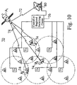
- Figure 10 represents a terrestrial two-way wireless (radio) communications system 70 which reuses frequencies on a cellular basis and uses LEO or MEO satellite links 72, 78 to connect remote receiver stations RT to a central or regional switching center 76 which is in turn connected to higher power service transmitters Tx.
- the system uses fixed location service transmitters Tx to transmit toward lower power mobile or portable subscriber units 74. Within the service area of a transmitter Tx, the subscriber units 74 are able to receive signals from the higher powered fixed location service transmitter Tx but they do not have enough power to transmit back to the fixed location service transmitter Tx. Satellite transceivers RT are deployed around the fixed location service transmitters to pick up the low power signals from the subscriber units 74 and relay the signal to a central or regional switching center 76.
- the central or regional switching center 76 is then able to complete a two way path for communications (for example, through the public switched telephone system) and is able to determine the general location of the subscriber unit 74 for the purpose of optimizing network traffic and service quality.
- the switching center 76 communicates to the satellite Ai through link 72 via the switching center antenna 80.
- the transceivers RT are coupled to the switching center 76 through links 78 to a satellite Ai and from the satellite Ai through link 72.
- the Radio Frequency Sharing Methods for Satellite System described above will provide frequency sharing among satellites of a new constellation and satellites that are already in orbit.
- the present invention will offer a wide range of communications services while enhancing the use of currently available spectrum.
Abstract
Description
- The present invention relates to the field of satellite communications and telecommunications systems. More particularly, this invention provides methods of frequency sharing for non-geostationary, store-and-forward, satellite communication systems.
- Over the past few decades, the demand for access to information has increased dramatically. Although conventional wire and fiber landlines, cellular networks and geostationary satellite systems have continued to expand in an attempt to meet this relentless growth in demand, the existing capacity is still not sufficient to meet the burgeoning global appetite for telecommunications services.
- Through technology advances and regulatory changes, mobile communication services were offered on a commercial basis and grew to meet city, regional, national and even international coverage needs through interconnection to public networks. As part of this evolution, wireless network standards have developed, on both a national and international basis, although there are still no truly international seamless wireless networks.
- The decline in price of mobile services is one of the most important forces helping mobile communications reach broad-based markets and demonstrate, rapid subscriber growth. The forces driving development of terrestrial wireless communications include advances in technology, declining prices and digital technology.
- The resulting reductions in service and equipment cost attributable to the factors described above have allowed mobile communications to penetrate both business and consumer markets. The ultimate goal of wireless services is to provide two-way, ubiquitous and affordable communications services. It was only very recently, with the introduction of mobile satellite services, that this has been made possible. Indeed, mobile satellite services are the final step in the evolution of wireless communications service and are the only services which can provide this ultimate goal of ubiquitous wireless communication.
- Currently, there are five major types of public mobile communications services used throughout the world:
- 1. Cellular, which provides primarily two-way, interconnected voice service with mobile, transportable, and portable telephones and providing a platform for data transmission;
- 2. Paging, which offers primarily one-way data transmission of numeric and alphanumeric messages;
- 3. Private Radio/SMR, which supplies primarily two-way voice service to closed user groups, but may also provide interconnected and mobile data services. SMR is a subset of private radio where service is provided on a commercial basis to businesses by carriers instead of the businesses owning their own systems;
- 4. Mobile Data, which provides networks for the exclusive transmission of mobile data; and
- 5. Personal Communications Services (PCS), which uses microcell technology, includes a wide range of voice and data services, for example, one-way outgoing PCS services, called CT-2, licensed in several countries such as the U.K., Taiwan and the Netherlands.
-
- The growth and evolution of mobile services show that subscribers migrate from basic limited services to more advanced services over time. The growth of terrestrial-based mobile services will increase the awareness and demand for enhanced mobile satellite services. Moreover, mobile satellite services will be able to provide service in areas that cannot be economically served using terrestrial networks.
- As a result of the advances in technology, privatization, and decreasing prices on a world-wide basis, wireless communications have undergone a rapid increase in subscriber growth in the past several years. The result is that new enhanced wireless services tend to gain market acceptance more rapidly than did earlier wireless technologies. This phenomenon is attributable to the increasing functionality, value relative to price, and awareness among the population of each successive technology. Paging was introduced with only one-way, non-voice communications at a relatively high price. SMR provided two-way communications, but only within a closed user-group. Finally, cellular offered two-way interconnected voice with increasingly wide area coverage. The result of the rapid growth in wireless services worldwide builds an awareness and future demand for the benefits of advanced wireless communications.
- Mobile satellite services are uniquely positioned to complete the evolution of wireless services. These services offer ubiquitous coverage, interconnection with other networks and a variety of services.
- Mobile satellites will be able to support both voice and data terminals, depending upon the particular need of the user. In general, however, voice service will be expensive relative to data, due to the greater infrastructure required for voice communications and the generally greater efficiency of data communications.
- Several previous efforts to enhance world-wide communications capabilities are briefly described. Robert R. Newton discloses a Multipurpose Satellite System in his U.S. Patent No. 3,497,807. Newton describes a system in which "any point on Earth is always within the line of sight of some satellite and any satellite is always within line of sight of an adjacent satellite in the same orbital plane." Col. 2, Lines 4-7.
- U.S. Patent No. 4,135,156 by Sanders et al., entitled Satellite Communications System Incorporating Ground Relay Station Through Which Messages Between Terminal Stations Are Routed, contains a description of a "satellite relay communications system" that "includes a ground relay station arranged so that each message from one subscriber to another is relayed by the satellite relay to the ground relay, processed by the ground relay and then transmitted to the second subscriber by way of the satellite relay." See Sanders et al., Abstract, Lines 1-6.
- Paul S. Visher disclosed a Satellite Arrangement Providing Effective Use of the Geostationary Orbit in his U.S. Patent No. 4,375,697. His patent recites a "satellite squadron or cluster formation" which "is disposed in a predetermined location in...geostationary orbit...." See Visher, Abstract, Lines 1-2.
- In their U.S. Patent No. 5.119,225, Michael Grant et al. explain their Multiple Access Communication System. The inventors describe a system that incorporates "a node spacecraft" in geostationary orbit that works in combination with "several user spacecraft" in low Earth orbit. See Grant et al., Abstract, Lines 1-3.
- The references cited above disclose telecommunication systems that include satellites deployed in polar, Equatorial and inclined low Earth orbits (LEO). The systems provide for transmitting a message between two low-power fixed or mobile terminals on the ground through a store-and-forward network. The store-and-forward relay method takes advantage of the geometry of a system which allows the satellites to fly over different parts of the globe frequently. These LEO systems do not provide access to a satellite one hundred per cent of the time. In the most populated areas of the globe, a user may have to wait for many minutes until a satellite flies into view.
- A burgeoning population of LEO communication satellites for commercial and military use is projected. Some observers estimate there will be 51 to 56 million users by the year 2002. To fill such a need for low-cost messaging and data communications available radio frequencies are required which may be packed into an already crowded very high frequency (VHF) and ultra high frequency (UHF) spectrum. Such spectrum already has many users.
- Current satellite communication systems use different frequencies simultaneously to communicate between many satellites in the same constellation which are "visible" to a user on the Earth's surface. The term "visible" is an analogy which refers to the fact that radio energy at VHF and UHF frequencies travel essentially in line-of-sight directions. To prevent interference between a satellite to or from which a transmission is expected and other satellites in the same system requires that one satellite transmit and receive at a different frequency. Often the same frequency is used only for satellites in different orbital positions or orbital planes. This is so-called space division multiple access (SDMA). Interference among multiple satellites "visible" at the same point on the Earth may also be prevented by operating different signals at different polarization, or by use of orthogonal spread-spectrum codes. Time division multiple access (TDMA) is a further method of preventing satellites in a particular constellation from interfering with communications by others in the same constellation. The same frequency may be employed by different satellites in the same constellation with overlapping radio beams, but only at different times.
- The U.S. Federal Communications System (FCC) and the International Telecommunications Union (ITU) have historically based assigned frequency spectrum to non-geostationary satellites on an exclusive use basis. That is, once assigned to a system, the frequency spectrum is unavailable for assignment to others wishing to operate in the same service region. In some cases, assignment of frequency spectrum to a system comprising a single satellite would preclude further use of that spectrum world wide.
- It would be a significant commercial advantage for a new system using a number of satellites to offer a user virtually immediate access to a satellite without interference. It would also be a commercial advantage, in some cases, to offer nearly instant, interference-free communication of the user's message to certain destinations. However, operation of numbers of new constellations of satellites presents a serious problem in that old constellations have been built and launched with little or no means of modifying their patterns of protection from communication interference. Therefore, providing a means, with minimum complexity, for spectrum sharing by new and older constellations would allow a significant increase in the available non-geostationary satellite communication services at lower cost than is presently possible.
- The development of a system which would reduce or obviate interference between satellites of a new constellation and satellites of an already exiting constellation would constitute a major technological advance and would satisfy a long felt need in the satellite and telecommunications industries.
- The current invention provides new methods for frequency spectrum sharing among satellites of a new constellation and satellites of an already existing constellation of non-geostationary satellites. For such satellites, potential radio frequency interference occurs at varying, but predictable times when satellite radio beams overlap on the Earth or satellites otherwise have conflicting regions of their coverage footprints. Two constellations of non-geostationary satellites have potentially interfering, overlapping coverage in many regions of the Earth simultaneously. Using the techniques of this invention, a new constellation of satellites can share frequency spectrum with several existing constellations which currently operate in mutually-exclusive frequency spectra. This is possible with a minimum of complexity and no impact to the existing constellation. Provision of a schedule of frequency use and orbital element data for the existing satellites is required. Sharing among more constellations provides additional frequency spectrum to allocate to satellites having potential conflicts. Therefore, the simultaneous coverage conjunction (areas where one or more satellites must be "turned off" to prevent frequency interference) of satellites of all constellations becomes smaller.
- One of the embodiments of the present invention supports a novel satellite, non-voice, non-geosynchronous communication system that includes a constellation of forty-eight satellites equally deployed in four pairs of low Earth orbits. These orbits are inclined at 50 degrees to the Equator. The satellites orbit in approximately orthogonal planes. A satellite leaves the Equator in one plane on an ascending node while a satellite in the orthogonal plane leaves the Equator on a descending node. The present invention, however, is not limited to such a constellation and is equally applicable to larger or smaller constellations. It is applicable to satellites in polar, inclined, or Equatorial orbits and circular, elliptical with varying foci, or highly elliptical orbits such as the Molnya orbit. The invention is independent of the type of communication service offered. The invention may be employed whenever the radio beams of one satellite in a constellation overlap those of another satellite in the same or in a different constellation. While this invention may be used for interference protection by satellites in geosynchronous (including geostationary) orbits, it is primarily concerned with preventing radio frequency interference (RFI) by new constellations of satellites in non-geosynchronous orbits with satellites in existing constellations.
- For communication systems such as the forty-eight satellite constellation mentioned above, user terminals located between 34 degrees and 54 degrees latitude, the most highly populated portion of the globe, have virtually continuous access to a satellite. A preferred method of communication provides a system for transmitting a message between two terminals on the ground through a store-and-forward network. For certain user terminals located in the upper latitudes, communication may be virtually instantaneous unless there are interfering signals from other satellites in different services which could block or cause retransmission of the message.
- The present invention will allow two or more satellite systems to utilize the same band of radio frequencies for communication between ground stations and satellites. This is accomplished by timing transmissions of each satellite in one constellation on one frequency or sets of frequencies so the transmissions visible at a point on the Earth do not occur simultaneously with transmissions by a satellite in a second constellation visible at the same point on the Earth on the same frequencies.
- In the following discussion, a first satellite constellation, newly launched, will be referred to as "System A" and a second, existing satellite constellation will be referred to as "System B." By spacing the System A satellites in each plane so that their radio coverage footprints on the Earth do not overlap except where the orbits cross, (usually new the polar region and in some constellations near the equatorial region), there is no interference among any of System A satellites. Newly launched System A must not interfere with existing System B. A System A satellite is required to change frequency to avoid interference with a System B satellite. The System A satellite must not use a frequency already in use by a second System A satellite which overlaps the first satellite's coverage. The System A first satellite must operate on a frequency assigned to a System A third orbital plane satellite that also does not overlap at the time. Happily, such a choice is generally available in LEO constellations so that required frequency changes do not ripple trough the constellation.
- To avoid having more than one satellite "visible" to a ground relay station, radio frequencies of System A satellites are allocated so that overlapping visibility contours are not assigned the same frequency. "Visible" refers to the fact that transmissions on very high frequency (VHF) or ultra high frequency (UHF) are essentially line of sight. Timing of transmissions by a satellite residing in System A is determined with reference to calculations of the ground visibility contours (radio beam footprints) of all of the satellites in System A and in those of satellites residing in System B and others if necessary. In one embodiment, a search algorithm as used to determine the choice of time and frequency in an automated fashion and scheduled days in advance.
- An ephemeris data set is constructed including orbital parameter data of all of the satellites in System A and System B. The orbital parameter data includes a continuous description of the position of the radio beam footprints wish time for each satellite. It also may include the operating radio frequencies assigned for each satellite in System B.
- A radio frequency use schedule is then constructed using a radio frequency use schedule algorithm in a conventional central processing unit (CPU). The algorithm is used to implement a frequency avoidance plan. The algorithm determines mutual visibility of a System A satellites and a System B satellites by a terminal on the Earth by calculating the distance between satellites based on the orbital data ephemeris. The algorithm determines which satellite in the System B is impacted by a satellite in System A. Only a satellite in System A which impacts another satellite is required to change frequency.
- The radio frequency use schedule is frequently updated to correct for satellite drift and other changes in satellite constellation topology. The radio frequency use schedule is periodically communicated by a ground relay station-to-satellite uplink to each satellite in System A where it is stored on board. Each satellite is then operated in accordance with the radio frequency use schedule. Frequency changes are made to avoid interfering with other satellites in the System A or System B.
- A preferred radio frequency use schedule algorithm that minimizes (or prohibits) System A satellites from causing interference to System B satellites also minimizes the system outages of System A. System A outages can be caused at times when no unused frequencies are available. Different frequencies are assigned to System A satellites in each orbit plane. Frequencies at the low end and high end of the frequency bands are interleaved to minimize the number of satellites that must change frequency for any overlapping footprint conflict. Any required frequency change is made by changing to the frequency assignment of a satellite in the System A constellation to a frequency assigned to satellites in an "orthogonal" orbit plane. If such a frequency is unavailable, then any available frequency is chosen.
- The frequency assignments to each of the eight orbital planes of System A are interleaved such that every odd numbered
orbit plane orbit plane - The methods described above may be applied to constellations described by J. G. Walker in his article Satellite Constellations, published in the Journal of the British Interplanetary Society, Vol. 37, 1984, pp. 559-572. Walker discloses methods for determining the size and shape of constellations of satellites able to provide continuous multiple coverage of the entire surface of the Earth needed for some applications such as navigation.
- In one preferred embodiment, the method described above is used with packet transmission store and forward protocols so that infrequent interference between satellites in the System A can be tolerated due to minimal degradation caused by burst packet transmissions and packet re-transmissions.
- In another, alternative embodiment, timing of the transmissions and frequency assignments is based on a satellite in System A detecting the use of a frequency by a satellite in System B and relaying that information between satellites in System A. Avoiding transmission on the same frequency by the two constellations requires all satellites in System A to detect transmissions in their field of view and change their transmitting frequency to a non-interfering frequency based on the frequency use information relayed between satellites in System A. In this embodiment, the radio frequency reuse schedule is computed on board each satellite based on the know position and frequencies of other satellites which is periodically furnished from a ground station.
- An appreciation of other aims and objectives of the present invention and a more complete and comprehensive understanding of this invention may be achieved by studying the following description of preferred and alternative embodiments and by referring to the accompanying drawings.
-
- Figure 1 is a schematic view of a constellation of forty-eight satellites in four pairs of inclined orbits. For the sake of clarity, only two pairs of orbits are shown.
- Figure 2a is a diagram showing how a satellite (A1) residing in a first constellation (System A) can transmit radio signals which, unless on a different frequency, can interfere with radio signals from another satellite (B1) residing in a second constellation (System B) when the two satellites are visible to a ground station. Satellite A2 may transmit on the same frequency as satellite B1 because of the spatial separation of the two satellites.
- Figure 2b is a diagram which depicts a satellite in System A which has a radio beam footprint overlapping the footprints of two satellites in System B which may be operating on the same frequency because of spatial separation. Simultaneously transmitted radio signals to and from the System A satellite will interfere with the signals to and from the System B satellites in the overlapping regions of the footprints.
- Figure 3 is a Mercator projection of the Earth's surface showing two satellites in different constellations whose radio beam footprints do not overlap. Interference is avoided if both satellites operate simultaneously on the same radio frequency.
- Figure 4 is a Mercator projection of the Earth's surface showing a plurality of satellites in two different constellations whose radio beam footprints overlap in the shaded areas, potentially causing radio frequency interference (RFI) between the two systems. For clarity, the diagram shows only radio beam footprints for satellites on or North of the Earth's Equator.
- Figures 5 and 6 are charts of signal energy versus frequency for communication signals used by satellites in System (fAll...fAnm) which occupy the same frequency bands as signals used by satellites in System B (fBl...fBn) showing how the signal frequencies are shared.
- Figure 7 is a schematic diagram of a preferred embodiment of the Radio Frequency Sharing for Satellite Systems depicting how orbital ephemeris data is used to create a radio frequency use schedule which is transmitted from a ground relay station via uplink to a System A satellite for use in timing the transmissions of the System A satellite which would otherwise interfere with System B satellites.
- Figure 8 is a schematic view of System A satellites Ai, Aj using an alternative embodiment of Radio Frequency Sharing for Satellite Systems. Satellites residing in System A listen for transmissions of satellites residing in System B and change frequency to prevent interference.
- Figure 9 reveals a diagram of the Earth and the orbital planes of System A satellites as seen from one pole, showing a plan for pairing frequency assignments among satellites in orthogonal orbital planes which minimizes the number of satellites in System A that must change frequency when a potential interference is caused by overlapping of System A radio-beam footprints by satellites of System B.
- Figure 10 represents a terrestrial two-way wireless (radio) communications system which reuses frequencies on a cellular basis and uses LEO or MEO satellite links to connect remote receiver stations to a central or regional switching center which is in turn connected to higher power service transmitters.
-
- Figure 1 is a schematic view of a
constellation 10 of forty-eight satellites (A ) operating in four conjugate pairs of
orbits 22 supported by a preferred embodiment of the present invention. For the sake of clarity, only two conjugate pairs oforbits 22 are shown. In the text that follows, the term "constellation" refers to the entire group of satellites. A complete implementation of the invention which incorporates theconstellation 10 as well as equipment such asrelay stations 18 oruser terminals 20 on or near the surface of the Earth E is described by the term "system." In the following discussion, afirst satellite constellation 10, newly launched, will be referred to as "System A" and a second, existing satellite constellation will be referred to as "System B." - The
satellites 12 shown in Figure 1 operate in one preferred embodiment, in acircular orbit Equator 16. In one preferred embodiment, the satellites (Aorbits 22 at an altitude of 950 km. The pairs oforbits 22 are positioned so that die ascending node of oneorbit 14 is displaced 180 degrees in right ascension (longitude) from the ascending node of the orthogonal,conjugate orbit 15. The ascending node of oneorbit 14 must therefore occur at the same angle of right ascension as does the descending node of the orthogonal,conjugate orbit 15. Ascending nodes of adjacent orbital planes are placed at 0, 45, 90, 135, 180, 225, 270 and 315 degrees right ascension. The interplane phase angle between any two adjacent orbital planes in one embodiment is zero degrees. In another embodiment, the interplane phase angle is 7.5 degrees. The interplane phase angle is the angle between two satellites A, A
Equator 16. - The
relay stations 18 are located on the ground and distributed internationally in a pattern of locations on the Earth which maximize coverage and minimize time to forward messages and data between any two user terminals. In a preferred embodiment of the System A, there are approximately ten to one hundred "distributed"relay stations 18. Therelay stations 18 are capable of communicating with the satellites Arelay stations 18 may be connected to terrestrial based networks such as public telephone networks. -
User terminals 20 are randomly distributed over the Earth's surface and are also capable of communicating with the satellites Auser terminals 20 may be fixed, mobile or portable. They may be located on land, at sea or in the air. - The parameters given above are for a preferred embodiment of a System A of communication satellites A

orbital plane orbital planes constellation 10 may be created in which the number of orbital planes (N) is an even, positive integer and the ascending nodes of the planes are positioned at right ascension angles of 0,180,360/N, 360/N+180,...,k*360/N, k*360/N+180,...,(N/2-1)*360/N, (N/2-1)*360/N+180 degrees. - The present invention has been designed from the outset to make efficient use of the scarce spectrum that is currently available. As an example of this scarcity, Table One below summarizes the total spectrum available in the U.S. for a typical non-voice non-geosynchronous (NVNG) type of service, resulting from the allocations made at WARC-92 and in the Federal Communication Commission's Order allocating spectrum for the NVNG Mobile Satellite Systems.
Mobile Satellite System Frequency Allocations Below 1 GHz Earth-to-Space Space-to-Earth 148.000 to 150.050 MHz 137.000 to 138.000 MHz 399.900 to 400.050 MHz 400.150 to 401.000 MHz - The table shows a total of 2.2 MHz available for the Earth-to-space links (uplink) and 1.85 MHz for the Space-to-Earth links (downlink). However, parts of this available spectrum are only allocated on a secondary basis to the MSS service, and even the primary MSS allocations are allocated on a co-primary basis to other services, such as Fixed, Mobile, Meteorological-Satellite, Space Operation, Space Research and Meteorological Aids. The ability of the system to effectively and efficiently share the spectrum in this type of environment is therefore of paramount importance.
- Figure 2a is a diagram showing how a satellite A1 residing in a first constellation (System A) can transmit radio signals which unless on a different frequency, can interfere with radio signals from another satellite B1 residing in a second constellation (System B). Satellite B1 is flying in
orbit 12. Satellites A1 and A2 are positioned in different orbits from the one satellite B1 is flying in. In its current position, satellite A1 is visible to the sameterrestrial relay station 18 oruser terminal 20 as is visible to satellite B1. "Visible" refers to the fact that transmissions at very high frequency (VHF) or ultra high frequency (UHF) and above are essentially line of sight. The two satellites A1, B1 are visible to theground relay station 18 oruser terminal 20 nearest satellite B1 in this figure. In its current position, satellite A2 is not visible to the sameterrestrial relay station 18 oruser terminal 20 as is either satellite A1 or satellite B1. Therefore, at their present positions, satellite A1 may not simultaneously transmit signals on the same frequency f2 as satellite B since the signal from satellite A1 will interfere with that of satellite B1 at theterrestrial relay station 18 oruser terminal 20 nearest satellite B1. Satellite A1 may transmit on the same frequency f1 as satellite A2 because the spatial separation of the two satellites prevents interference between the two signals at theterrestrial station 18 oruser terminal 20. Satellite A2 may also transmit simultaneously with satellite B1 on frequency f2 because the spatial separation of the two satellites A2, B1 prevents interference between the two signals at theterrestrial station 18 nearest satellite B1. - Figure 2b is a diagram which depicts a satellite in System A which has a
radio beam footprint 30 overlapping thefootprint 35 of each of two System B satellites B1, B2. Satellites B1 and B2 may be operating on the same frequency because spatial separation permits them to do so. Radio beams 36 to and from System A satellite A1 in the overlappingregions 34 of thefootprints regions 34. - Figure 3 is a
Mercator projection 37a of the Earth's surface showingradio beam footprints radio beam footprints - Figure 4 is a
Mercator projection 37b of the Earth's surface showing a plurality of satellites in two different Systems A, B whoseradio beam footprints areas 34. For clarity, the projection has been limited tosatellites having footprints latitudes 38 of sixty degrees North and thirty degrees South. There is potential radio frequency interference (RFI) in the overlapping (shaded)areas 34, if simultaneous transmissions on the same frequencies (f1) are made by satellites whosefootprints - For
certain user terminals 20 located in the these upper latitudes, communication may be virtually instantaneous unless there are interfering signals from other satellites (B - Figure 5 is a chart of signal energy versus frequency for communication signals usable by satellites in System A (fAll...fAln) which occupy the first frequency band used by satellites in System B (fBl). Figure 6 is a chart of signal energy versus frequency for communication signals used by the satellites in System A (fAml...fAmn) which occupy the mth band used by satellites in System B (fBmn). Satellites in System B operate using frequency bands fBl...fBm. Satellites in System A operate using frequency bands fAll...fAnm. These charts depict graphically how the limited signal frequencies available are shared by satellites in System A and System B.
- To avoid having more than one satellite "visible" to a
ground relay station 18, radio frequencies of System A satellites are allocated so that overlapping visibility contours are not assigned the same frequency. Timing of transmissions by a satellite residing in System A is determined with reference to calculations of the ground visibility contours (radio beam footprints) of all of the satellites in System A and in those of satellites residing in System B and others if necessary. - The present invention will allow two or more satellite Systems A, B to utilize the same band of radio frequencies for communication between
ground stations terrestrial terminals overlap area 34 ofradio beams satellite footprints regions 34. - Figure 7 is a schematic diagram of a preferred embodiment of the Radio Frequency Sharing Methods for Satellite Systems. It depicts how
orbital ephemeris data 46 is used to create a radiofrequency use schedule 49 which is transmitted from aground relay station 18 via uplink to a satellite for use in timing transmissions of the System A satellite Ai which would otherwise interfere with one or more System B satellites. - Orbital data and radio frequency assignments for satellites A
orbital data ephemeris 46. The position ofsatellite footprints use schedule algorithm 48 to produce afrequency use schedule 49. Storage of theephemeris data 46 and computation of the radiofrequency use schedule 49 is accomplished by conventional computing means. The radiofrequency use schedule 49 is transmitted periodically as necessary to each satellite Ai residing in System A by anuplink 50 from aground relay station 18. - Figure 8 is a schematic view of System A satellites using an alternative embodiment of Radio Frequency Sharing Methods for Satellite Systems. Satellites residing in System A listen for transmissions of satellites residing in System B to determine when to change transmission frequency. The frequency intercepted by satellite Ai is sent to all satellites in the system. In this embodiment, the
orbital parameter ephemeris 46 is maintained on board each satellite Afrequency use schedule 49 is computed on board the satellites Ause schedule algorithm 48. Of course, theephemeris 46 andalgorithm 48 may be also maintained and computed on the Earth in the event cost and power use are to be conserved. In that event, the satellite which intercepts the frequency being used by the System B satellite B1 transmits the information to the nearestground relay station 18 for processing. - A frequency assignment plan for System A satellites A
radio coverage footprints 30 on the Earth E do not overlap except where theorbits - The schedule of these events, as described above, can be stored on board each satellite. Frequency changes can be executed by on-board command at the appropriate time or commanded in real time by a ground control station, using cross-links between satellites A
- For the system of 48 satellites A
orbital planes orbital planes beam footprint 30 by afootprint 35 of System B satellites Bconjugate planes plane 1 are assigned to frequency f1. Satellites inplane 2 are assigned to frequency f6, satellites inplane 3 are assigned to frequency f3, and so forth as shown in Figure 9. At such time as a satellite must change frequency to avoid a conflict with another with overlapping coverage, the frequency is changed to that of the frequency assigned to satellites in the orthogonal orbit plane, if available. As a result, a satellite inplane 1 would shift to f5, the frequency assigned toplane 5; a satellite inplane 2 would shift to f2, the frequency assigned toplane 5; a satellite inplane 3 would shift to f7; a satellite inplane 4 would shift to f4; a satellite inplane 5 would shift to f1; a satellite inplane 6 would shift to f2; a satellite inplane 7 would shift to f3; and a satellite inplane 8 would shift to f8. - By switching to frequencies from
orthogonal planes 15, conflicts are avoided, except near the polar region, for the constellation depicted in Figure 9. Because many satellites can service the polar regions, little or no coverage is lost even if one satellite A - In the case of some conflicting satellite systems, such pairing minimizes the probability of a System
B overlapping footprint 35 requiring a change in more than two frequencies. As has been noted previously, the radio frequency use algorithm implements such pairings and choices for frequency changes. For a time when an interference is predicted, the algorithm will require a frequency change from that first assigned to that of anorthogonal plane 15. If a selected frequency is unavailable then any available frequency is selected. At least one frequency is always available. - The frequency assignments to each of the eight orbital planes of System A are interleaved such that every odd numbered
orbit plane orbit plane orbital planes orbital planes - When a frequency change is necessary for a satellite A
orthogonal plane 15, if available, is adopted by that satellite. If the selected frequency is not available then any available frequency may be used. Of course, the order of frequency assignment, from lowest to highest, and the portion of the band assigned to odd or even numberedplanes - Much of the time, there are usually two System A orbit planes, each assigned a different frequency, in which
satellite footprints 30 do not present radio interference withfootprints 30 in the other planes. These two planes are always adjacent planes. Therefore, interleaving the frequency assignments in each plane such that every other frequency is in an opposite half of the available spectrum, increases the probability that a frequency will be available to which a System A satellite in conflict can switch. - In the System B constellation postulated, only half of the available spectrum is required. Therefore only one-half of the System A satellites A
- The methods described above may be applied to constellations described by J. G. Walker in his article Satellite Constellations, published in the Journal of the British Interplanetary Society, Vol. 37, 1984, pp. 559-572. Walker discloses methods for determining the size and shape of constellations of satellites able to provide continuous multiple coverage of the entire surface of the Earth needed for some applications such as navigation. These constellations require precise phasing of satellites in each orbit plane and between orbit planes. This results in a regular pattern of overlapping 34 and
non-overlapping footprints - A typical Walker constellation for System A might comprise 48 satellites in eight orbit planes, inclined at 50 degrees, the satellites being spaced 60 degrees apart along the plane of orbit. The satellites are phased at 7.5 degrees (a satellite in one plane has advanced 7.5 degrees from the equator EQ when a satellite in an adjacent plane is just crossing the equator EQ). At 950 km altitude, there is no interference between satellites in the same plane since their radio horizons, and hence their footprints do not overlap.
- As each System A satellite travels in its orbit plane, its
footprint 30 overlaps with four of its neighboring satellites in adjacent planes on either side. Thus frequencies assigned to these adjacent planes can never be used by the affected satellite. Similar patterns exist for all satellites in the constellation. - As in the case of the constellation described above, in a System A Walker constellation there are usually two orbit planes in which satellites do not present radio interference with satellites in the other planes. As a result, conflicts between a System A and a System B satellite during this time can be obviated by switching the System A satellite to one of the two non-conflicting frequencies.
- For a short period of time, twice each orbital revolution, a System A satellite is in contact with satellites in all System A orbital planes. During this time, if there is a conflict between a System A satellite and a System B satellite, the conflict cannot be resolved without changing the frequency of two System A satellites unless an additional frequency outside of System A assignments is available. If a System C frequency is available that is not used by System B, it can be used by an impacted System A satellite. The inclusion of a third (System C) constellation's spectrum in the spectrum available to System A can facilitate frequency sharing and increase spectrum reuse.
- The above examples of frequency sharing plans do not exhaust all of the possibilities but serve to illustrate the process of selecting and assigning communication frequencies which will prevent or at least minimize frequency conflicts between satellites in newly launched constellations and existing ones, without impacting the existing constellations.
- Figure 10 represents a terrestrial two-way wireless (radio)
communications system 70 which reuses frequencies on a cellular basis and uses LEO or MEO satellite links 72, 78 to connect remote receiver stations RT to a central orregional switching center 76 which is in turn connected to higher power service transmitters Tx. The system uses fixed location service transmitters Tx to transmit toward lower power mobile orportable subscriber units 74. Within the service area of a transmitter Tx, thesubscriber units 74 are able to receive signals from the higher powered fixed location service transmitter Tx but they do not have enough power to transmit back to the fixed location service transmitter Tx. Satellite transceivers RT are deployed around the fixed location service transmitters to pick up the low power signals from thesubscriber units 74 and relay the signal to a central orregional switching center 76. The central orregional switching center 76 is then able to complete a two way path for communications (for example, through the public switched telephone system) and is able to determine the general location of thesubscriber unit 74 for the purpose of optimizing network traffic and service quality. The switchingcenter 76 communicates to the satellite Ai throughlink 72 via theswitching center antenna 80. The transceivers RT are coupled to theswitching center 76 throughlinks 78 to a satellite Ai and from the satellite Ai throughlink 72. - The Radio Frequency Sharing Methods for Satellite System described above will provide frequency sharing among satellites of a new constellation and satellites that are already in orbit. The present invention will offer a wide range of communications services while enhancing the use of currently available spectrum.
- Although the present invention has been described in detail with reference to a particular preferred embodiment and alternative embodiment, persons possessing ordinary skill in the art to which this invention pertains will appreciate that various modifications and enhancements may be made without departing from the scope of the claims that follow. The various orbital parameters, altitudes and constellation populations, locations of the
user terminals 20 andrelay stations 18 and frequency avoidance plans implemented by the frequencyuse schedule algorithm 48 that have been disclosed above are intended to educate the reader about preferred embodiments, and are not intended to constrain the limits of the invention or the scope of the Claims. The List of Reference Characters which follows is intended to provide the reader with a convenient means of identifying elements of the invention in the Specification and Drawings. This list is not intended to delineate or narrow the scope of the Claims. -
- Figures 1 through 9
- 10
- Constellation or System "A" of satellites
- 12
- Orbit of constellation or System "B" satellites
- 14
- Orbital plane of System "A" satellites
- 15
- Orthogonal orbital plane of System "A" satellites
- 16
- Equator
- 18
- Ground relay station
- 20
- Distributed user terminals
- 22
- Orthogonal pairs of satellite orbits
- 30
- Footprint of radio beam from A constellation satellite
- 32
- Radio beam from B constellation satellite
- 34
- Overlap of footprints of radio beams from A and B System satellites
- 35
- Footprint of radio beam from System B satellite
- 36
- Radio beam from System A satellite
- 37a
- Mercator projection of the Earth and footprints of one System A satellite and one System B satellite
- 37b
- Mercator projection of the Earth and footprints of a plurality of System A satellites overlapping a plurality of footprints of System B satellites
- 38
- Latitude Scale of Mercator projection of the globe
- 39
- Longitude scale of Mercator projection of the globe
- 40
- Radio frequency spectrum used by a System B first satellite
- 42
- Radio frequency spectrum used by a System B Nth satellite
- 46
- Orbital ephemeris electronic data table
- 48
- Radio frequency use schedule algorithm computation
- 49
- Computed frequency-use schedule electronic data
- 50
- Ground relay station-to-satellite uplink
- 60
- Intersatellite radio link
- 70
- Terrestrial two-way wireless system
- 72
- LEO/MEO satellite-to-switching center link
- 74
- Remote receiver
- 76
- Central or regional switching center
- 78
- Remote transceiver-to-satellite link
- 80
- Switching center antenna
- A1
- First satellite in System A constellation
- A2
- Second satellite in System A constellation
- A
- Last satellite in System A constellation
- Ai
- ith satellite in System A constellation
- Aj
- jth satellite in System A constellation
- fAkl
- Radio frequencies used by System A satellites: k=l...n; l=l...m
- fBp
- Radio frequencies used by System B satellites: p=l...n
- B1
- First satellite in System B constellation
- B2
- Second satellite in System B constellation
- Bi
- ith satellite in System B constellation
- B
- Last satellite in System B constellation
- Ci
- ith satellite in a third or System C constellation
- E
- Earth
- EQ
- Equator
- fi
- ith frequency used by satellites
- t
- Time period for frequency use
- m
- Number of frequency bands used by System A
- n
- Number of frequency bands used by System B
- RT
- Transceiver station
- Tx
- Fixed-location service transmitter
-
Claims (4)
- A two-way communications system for a portable, low-power mobile or fixed subscriber unit (74), using a satellite communication system, comprising:a central switching centre (76):said central switching centre (76) being connected to a satellite (Ai) through a satellite radio link (72) and being connected to a public switched telephone network (PSTN);a plurality of fixed location service transmitters (Tx); each one of said plurality of fixed location service transmitters (Tx) being coupled to said central switching centre (76), each one of said fixed location service transmitters (Tx) providing communications transmissions to said subscriber unit (74) within an omnidirectional service area;a plurality of remote transceiver stations (RT), each one of said remote transceiver station (RT) being coupled to said central switching centre (76) through a satellite radio link (78) to said satellite; andsaid remote transceiver stations (RT) being deployed in said service areas around said fixed location service transmitters (Tx) and capable of receiving low power signals from said subscriber unit (74);said low-power signals from said subscriber unit (74) being received by said remote transceiver (RT) and relayed to said public switched telephone system (PSTN) through satellite radio links (78, 72) and said central switching centre (76);communications from said public switched telephone network system (PSTN) being relayed to said subscriber unit (74) directly from said service transmitter (Tx), whereby a two-way communication path is completed, and a general location of said subscriber unit (74) is determined for the purpose of optimizing network traffic and service quality.
- A system according to claim 1 wherein said satellite is a non-geosynchronous orbiting satellite.
- A system according to claim 2, wherein said satellite is LEO satellite.
- A system according to claim 2, wherein said satellite is a MEO satellite.
Applications Claiming Priority (3)
| Application Number | Priority Date | Filing Date | Title |
|---|---|---|---|
| US08/703,228 US5926758A (en) | 1996-08-26 | 1996-08-26 | Radio frequency sharing methods for satellite systems |
| US703228 | 1996-08-26 | ||
| EP97938264A EP0929950A1 (en) | 1996-08-26 | 1997-08-18 | Radio frequency sharing methods for satellite systems |
Related Parent Applications (1)
| Application Number | Title | Priority Date | Filing Date |
|---|---|---|---|
| EP97938264A Division EP0929950A1 (en) | 1996-08-26 | 1997-08-18 | Radio frequency sharing methods for satellite systems |
Publications (2)
| Publication Number | Publication Date |
|---|---|
| EP1035663A2 true EP1035663A2 (en) | 2000-09-13 |
| EP1035663A3 EP1035663A3 (en) | 2001-12-19 |
Family
ID=24824555
Family Applications (2)
| Application Number | Title | Priority Date | Filing Date |
|---|---|---|---|
| EP97938264A Withdrawn EP0929950A1 (en) | 1996-08-26 | 1997-08-18 | Radio frequency sharing methods for satellite systems |
| EP00107683A Withdrawn EP1035663A3 (en) | 1996-08-26 | 1997-08-18 | Two-way communication system for mobile users using a satellite system |
Family Applications Before (1)
| Application Number | Title | Priority Date | Filing Date |
|---|---|---|---|
| EP97938264A Withdrawn EP0929950A1 (en) | 1996-08-26 | 1997-08-18 | Radio frequency sharing methods for satellite systems |
Country Status (5)
| Country | Link |
|---|---|
| US (1) | US5926758A (en) |
| EP (2) | EP0929950A1 (en) |
| AU (1) | AU4063997A (en) |
| CA (1) | CA2264161A1 (en) |
| WO (1) | WO1998009386A1 (en) |
Cited By (1)
| Publication number | Priority date | Publication date | Assignee | Title |
|---|---|---|---|---|
| WO2016053389A1 (en) * | 2014-09-30 | 2016-04-07 | Google Inc. | Satellite constellation |
Families Citing this family (121)
| Publication number | Priority date | Publication date | Assignee | Title |
|---|---|---|---|---|
| US6650898B2 (en) * | 1992-03-06 | 2003-11-18 | Aircell, Inc. | Signal translating repeater for enabling a terrestrial mobile subscriber station to be operable in a non-terrestrial environment |
| US6108539A (en) * | 1992-03-06 | 2000-08-22 | Aircell, Incorporated | Non-terrestrial cellular mobile telecommunication station |
| US6725035B2 (en) * | 1992-03-06 | 2004-04-20 | Aircell Inc. | Signal translating repeater for enabling a terrestrial mobile subscriber station to be operable in a non-terrestrial environment |
| US6101385A (en) * | 1997-10-09 | 2000-08-08 | Globalstar L.P. | Satellite communication service with non-congruent sub-beam coverage |
| US6434384B1 (en) | 1997-10-17 | 2002-08-13 | The Boeing Company | Non-uniform multi-beam satellite communications system and method |
| US6198907B1 (en) * | 1998-02-02 | 2001-03-06 | Motorola, Inc. | Satellite communications systems using satellites in a zero-drift constellation |
| US6240074B1 (en) * | 1998-02-19 | 2001-05-29 | Motorola, Inc. | Secure communication hub and method of secure data communication |
| DE19836145A1 (en) * | 1998-08-10 | 2000-02-17 | Siemens Ag | Mobile telecommunications device |
| US7327698B1 (en) * | 1999-06-03 | 2008-02-05 | The Directv Group, Inc. | Method and system for providing satellite communications using on-orbit payload configuration and reconfiguration |
| GB2352363A (en) * | 1999-07-21 | 2001-01-24 | Ico Services Ltd | Satellite communications system with broadcast channel switching |
| US20030149986A1 (en) * | 1999-08-10 | 2003-08-07 | Mayfield William W. | Security system for defeating satellite television piracy |
| US7174127B2 (en) * | 1999-08-10 | 2007-02-06 | Atc Technologies, Llc | Data communications systems and methods using different wireless links for inbound and outbound data |
| AU7575300A (en) * | 1999-09-14 | 2001-04-17 | Globalstar L.P. | Dynamic satellite filter controller for leo satellites |
| US6859652B2 (en) * | 2000-08-02 | 2005-02-22 | Mobile Satellite Ventures, Lp | Integrated or autonomous system and method of satellite-terrestrial frequency reuse using signal attenuation and/or blockage, dynamic assignment of frequencies and/or hysteresis |
| US8265637B2 (en) | 2000-08-02 | 2012-09-11 | Atc Technologies, Llc | Systems and methods for modifying antenna radiation patterns of peripheral base stations of a terrestrial network to allow reduced interference |
| US7149526B2 (en) * | 2000-08-02 | 2006-12-12 | Atc Technologies, Llc | Coordinated satellite-terrestrial frequency reuse |
| US7558568B2 (en) * | 2003-07-28 | 2009-07-07 | Atc Technologies, Llc | Systems and methods for modifying antenna radiation patterns of peripheral base stations of a terrestrial network to allow reduced interference |
| US6810249B1 (en) * | 2000-09-19 | 2004-10-26 | The Directv Group, Inc. | Method and system of efficient spectrum utilization by communications satellites |
| US7792488B2 (en) | 2000-12-04 | 2010-09-07 | Atc Technologies, Llc | Systems and methods for transmitting electromagnetic energy over a wireless channel having sufficiently weak measured signal strength |
| US6785543B2 (en) | 2001-09-14 | 2004-08-31 | Mobile Satellite Ventures, Lp | Filters for combined radiotelephone/GPS terminals |
| US7890098B2 (en) * | 2001-09-14 | 2011-02-15 | Atc Technologies, Llc | Staggered sectorization for terrestrial reuse of satellite frequencies |
| US7603081B2 (en) | 2001-09-14 | 2009-10-13 | Atc Technologies, Llc | Radiotelephones and operating methods that use a single radio frequency chain and a single baseband processor for space-based and terrestrial communications |
| US7603117B2 (en) | 2001-09-14 | 2009-10-13 | Atc Technologies, Llc | Systems and methods for terrestrial use of cellular satellite frequency spectrum |
| US7006789B2 (en) * | 2001-09-14 | 2006-02-28 | Atc Technologies, Llc | Space-based network architectures for satellite radiotelephone systems |
| US7113778B2 (en) * | 2001-09-14 | 2006-09-26 | Atc Technologies, Llc | Aggregate radiated power control for multi-band/multi-mode satellite radiotelephone communications systems and methods |
| US7155340B2 (en) * | 2001-09-14 | 2006-12-26 | Atc Technologies, Llc | Network-assisted global positioning systems, methods and terminals including doppler shift and code phase estimates |
| US7792069B2 (en) * | 2001-09-14 | 2010-09-07 | Atc Technologies, Llc | Systems and methods for terrestrial reuse of cellular satellite frequency spectrum using different channel separation technologies in forward and reverse links |
| US7623859B2 (en) * | 2001-09-14 | 2009-11-24 | Atc Technologies, Llc | Additional aggregate radiated power control for multi-band/multi-mode satellite radiotelephone communications systems and methods |
| US6999720B2 (en) * | 2001-09-14 | 2006-02-14 | Atc Technologies, Llc | Spatial guardbands for terrestrial reuse of satellite frequencies |
| US7664460B2 (en) | 2001-09-14 | 2010-02-16 | Atc Technologies, Llc | Systems and methods for terrestrial reuse of cellular satellite frequency spectrum in a time-division duplex and/or frequency-division duplex mode |
| US7181161B2 (en) * | 2001-09-14 | 2007-02-20 | Atc Technologies, Llc | Multi-band/multi-mode satellite radiotelephone communications systems and methods |
| US8270898B2 (en) | 2001-09-14 | 2012-09-18 | Atc Technologies, Llc | Satellite-band spectrum utilization for reduced or minimum interference |
| US7218931B2 (en) * | 2001-09-14 | 2007-05-15 | Atc Technologies, Llc | Satellite radiotelephone systems providing staggered sectorization for terrestrial reuse of satellite frequencies and related methods and radiotelephone systems |
| US7062267B2 (en) * | 2001-09-14 | 2006-06-13 | Atc Technologies, Llc | Methods and systems for modifying satellite antenna cell patterns in response to terrestrial reuse of satellite frequencies |
| US7593724B2 (en) | 2001-09-14 | 2009-09-22 | Atc Technologies, Llc | Systems and methods for terrestrial reuse of cellular satellite frequency spectrum in a time-division duplex mode |
| US7447501B2 (en) * | 2001-09-14 | 2008-11-04 | Atc Technologies, Llc | Systems and methods for monitoring selected terrestrially used satellite frequency signals to reduce potential interference |
| US6653975B2 (en) * | 2001-11-21 | 2003-11-25 | Northrop Grumman Corporation | Method of configuring satellite constellation design using multiple discrete switchable spot beams |
| US8027637B1 (en) * | 2002-01-11 | 2011-09-27 | Broadcom Corporation | Single frequency wireless communication system |
| US6856787B2 (en) | 2002-02-12 | 2005-02-15 | Mobile Satellite Ventures, Lp | Wireless communications systems and methods using satellite-linked remote terminal interface subsystems |
| US7593691B2 (en) * | 2002-02-12 | 2009-09-22 | Atc Technologies, Llc | Systems and methods for controlling a level of interference to a wireless receiver responsive to a power level associated with a wireless transmitter |
| US6937857B2 (en) | 2002-05-28 | 2005-08-30 | Mobile Satellite Ventures, Lp | Systems and methods for reducing satellite feeder link bandwidth/carriers in cellular satellite systems |
| US7092708B2 (en) * | 2002-12-12 | 2006-08-15 | Atc Technologies, Llc | Systems and methods for increasing capacity and/or quality of service of terrestrial cellular and satellite systems using terrestrial reception of satellite band frequencies |
| US7421342B2 (en) * | 2003-01-09 | 2008-09-02 | Atc Technologies, Llc | Network-assisted global positioning systems, methods and terminals including doppler shift and code phase estimates |
| US7444170B2 (en) * | 2003-03-24 | 2008-10-28 | Atc Technologies, Llc | Co-channel wireless communication methods and systems using nonsymmetrical alphabets |
| US7203490B2 (en) | 2003-03-24 | 2007-04-10 | Atc Technologies, Llc | Satellite assisted push-to-send radioterminal systems and methods |
| US6879829B2 (en) * | 2003-05-16 | 2005-04-12 | Mobile Satellite Ventures, Lp | Systems and methods for handover between space based and terrestrial radioterminal communications, and for monitoring terrestrially reused satellite frequencies at a radioterminal to reduce potential interference |
| US20040240525A1 (en) * | 2003-05-29 | 2004-12-02 | Karabinis Peter D. | Wireless communications methods and apparatus using licensed-use system protocols with unlicensed-use access points |
| US7340213B2 (en) * | 2003-07-30 | 2008-03-04 | Atc Technologies, Llc | Intra- and/or inter-system interference reducing systems and methods for satellite communications systems |
| US8670705B2 (en) * | 2003-07-30 | 2014-03-11 | Atc Technologies, Llc | Additional intra-and/or inter-system interference reducing systems and methods for satellite communications systems |
| US20050041619A1 (en) * | 2003-08-22 | 2005-02-24 | Karabinis Peter D. | Wireless systems, methods and devices employing forward- and/or return-link carriers having different numbers of sub-band carriers |
| US7113743B2 (en) | 2003-09-11 | 2006-09-26 | Atc Technologies, Llc | Systems and methods for inter-system sharing of satellite communications frequencies within a common footprint |
| KR101049422B1 (en) | 2003-09-23 | 2011-07-15 | 에이티씨 테크놀로지즈, 엘엘씨. | System and method for mobility management in overlay satellite and terrestrial communication system |
| US8380186B2 (en) | 2004-01-22 | 2013-02-19 | Atc Technologies, Llc | Satellite with different size service link antennas and radioterminal communication methods using same |
| US7418236B2 (en) * | 2004-04-20 | 2008-08-26 | Mobile Satellite Ventures, Lp | Extraterrestrial communications systems and methods including ancillary extraterrestrial components |
| US8655398B2 (en) | 2004-03-08 | 2014-02-18 | Atc Technologies, Llc | Communications systems and methods including emission detection |
| US7453920B2 (en) | 2004-03-09 | 2008-11-18 | Atc Technologies, Llc | Code synchronization in CDMA satellite wireless communications system using uplink channel detection |
| US7933552B2 (en) * | 2004-03-22 | 2011-04-26 | Atc Technologies, Llc | Multi-band satellite and/or ancillary terrestrial component radioterminal communications systems and methods with combining operation |
| US7606590B2 (en) | 2004-04-07 | 2009-10-20 | Atc Technologies, Llc | Satellite/hands-free interlock systems and/or companion devices for radioterminals and related methods |
| US7636566B2 (en) * | 2004-04-12 | 2009-12-22 | Atc Technologies, Llc | Systems and method with different utilization of satellite frequency bands by a space-based network and an ancillary terrestrial network |
| US20050239399A1 (en) * | 2004-04-21 | 2005-10-27 | Karabinis Peter D | Mobile terminals and set top boxes including multiple satellite band service links, and related systems and methods |
| US8265549B2 (en) * | 2004-05-18 | 2012-09-11 | Atc Technologies, Llc | Satellite communications systems and methods using radiotelephone |
| US20050260984A1 (en) * | 2004-05-21 | 2005-11-24 | Mobile Satellite Ventures, Lp | Systems and methods for space-based use of terrestrial cellular frequency spectrum |
| WO2006012348A2 (en) * | 2004-06-25 | 2006-02-02 | Atc Technologies, Llc | Method and system for frequency translation on-board a communications satellite |
| BRPI0514246A (en) | 2004-08-11 | 2008-06-03 | Atc Tech Llc | method of operating a first and / or second communication system, radiotherapy, communications system, and method for operating a radiotherapy |
| US20060094420A1 (en) * | 2004-11-02 | 2006-05-04 | Karabinis Peter D | Multi frequency band/multi air interface/multi spectrum reuse cluster size/multi cell size satellite radioterminal communicaitons systems and methods |
| US7639981B2 (en) * | 2004-11-02 | 2009-12-29 | Atc Technologies, Llc | Apparatus and methods for power control in satellite communications systems with satellite-linked terrestrial stations |
| AU2005307841B2 (en) * | 2004-11-16 | 2010-03-25 | Atc Technologies, Llc | Satellite communications systems, components and methods for operating shared satellite gateways |
| US7747229B2 (en) * | 2004-11-19 | 2010-06-29 | Atc Technologies, Llc | Electronic antenna beam steering using ancillary receivers and related methods |
| US7454175B2 (en) * | 2004-12-07 | 2008-11-18 | Atc Technologies, Llc | Broadband wireless communications systems and methods using multiple non-contiguous frequency bands/segments |
| US8594704B2 (en) * | 2004-12-16 | 2013-11-26 | Atc Technologies, Llc | Location-based broadcast messaging for radioterminal users |
| EP1844558B1 (en) | 2005-01-05 | 2018-02-14 | ATC Technologies, LLC | Adaptive beam forming with multi-user detection and interference reduction in satellite communication systems and methods |
| EP1847071A4 (en) * | 2005-01-26 | 2010-10-20 | Internet Broadcasting Corp B V | Layered multicast and fair bandwidth allocation and packet prioritization |
| US7596111B2 (en) | 2005-01-27 | 2009-09-29 | Atc Technologies, Llc | Satellite/terrestrial wireless communications systems and methods using disparate channel separation codes |
| US7636546B2 (en) * | 2005-02-22 | 2009-12-22 | Atc Technologies, Llc | Satellite communications systems and methods using diverse polarizations |
| EP1851877A2 (en) * | 2005-02-22 | 2007-11-07 | ATC Technologies, LLC | Reusing frequencies of a fixed and/or mobile communications system |
| US7738837B2 (en) * | 2005-02-22 | 2010-06-15 | Atc Technologies, Llc | Satellites using inter-satellite links to create indirect feeder link paths |
| US7756490B2 (en) * | 2005-03-08 | 2010-07-13 | Atc Technologies, Llc | Methods, radioterminals, and ancillary terrestrial components for communicating using spectrum allocated to another satellite operator |
| US7587171B2 (en) * | 2005-03-09 | 2009-09-08 | Atc Technologies, Llc | Reducing interference in a wireless communications signal in the frequency domain |
| US7796986B2 (en) | 2005-03-11 | 2010-09-14 | Atc Technologies, Llc | Modification of transmission values to compensate for interference in a satellite down-link communications |
| US7627285B2 (en) * | 2005-03-14 | 2009-12-01 | Atc Technologies, Llc | Satellite communications systems and methods with distributed and/or centralized architecture including ground-based beam forming |
| US7634229B2 (en) * | 2005-03-15 | 2009-12-15 | Atc Technologies, Llc | Intra-system and/or inter-system reuse of feeder link frequencies including interference suppression systems and methods |
| WO2006099501A1 (en) * | 2005-03-15 | 2006-09-21 | Atc Technologies, Llc | Methods and systems providing adaptive feeder links for ground based beam forming and related systems and satellites |
| US7453396B2 (en) * | 2005-04-04 | 2008-11-18 | Atc Technologies, Llc | Radioterminals and associated operating methods that alternate transmission of wireless communications and processing of global positioning system signals |
| DE102005027453A1 (en) * | 2005-06-14 | 2006-12-28 | Fraunhofer-Gesellschaft zur Förderung der angewandten Forschung e.V. | Terrestrial transmitting station for broadcasting a terrestrial broadcasting signal, satellite-based broadcasting system and receiver for a satellite-based broadcasting system |
| US7817967B2 (en) | 2005-06-21 | 2010-10-19 | Atc Technologies, Llc | Communications systems including adaptive antenna systems and methods for inter-system and intra-system interference reduction |
| US7970345B2 (en) | 2005-06-22 | 2011-06-28 | Atc Technologies, Llc | Systems and methods of waveform and/or information splitting for wireless transmission of information to one or more radioterminals over a plurality of transmission paths and/or system elements |
| US7907944B2 (en) | 2005-07-05 | 2011-03-15 | Atc Technologies, Llc | Methods, apparatus and computer program products for joint decoding of access probes in a CDMA communications system |
| US8190114B2 (en) | 2005-07-20 | 2012-05-29 | Atc Technologies, Llc | Frequency-dependent filtering for wireless communications transmitters |
| US7623867B2 (en) | 2005-07-29 | 2009-11-24 | Atc Technologies, Llc | Satellite communications apparatus and methods using asymmetrical forward and return link frequency reuse |
| US7461756B2 (en) * | 2005-08-08 | 2008-12-09 | Plastipak Packaging, Inc. | Plastic container having a freestanding, self-supporting base |
| ATE466417T1 (en) | 2005-08-09 | 2010-05-15 | Atc Tech Llc | SATELLITE COMMUNICATION SYSTEMS AND METHODS USING SUBSTANTIALLY ADJACENT RADIO CONNECTION ANTENNAS |
| WO2007047370A2 (en) * | 2005-10-12 | 2007-04-26 | Atc Technologies, Llc | Systems, methods and computer program products for mobility management in hybrid satellite/terrestrial wireless communications systems |
| US7979024B2 (en) * | 2006-01-20 | 2011-07-12 | Atc Technologies, Llc | Systems and methods for satellite forward link transmit diversity using orthagonal space coding |
| US8705436B2 (en) * | 2006-02-15 | 2014-04-22 | Atc Technologies, Llc | Adaptive spotbeam broadcasting, systems, methods and devices for high bandwidth content distribution over satellite |
| US8923850B2 (en) * | 2006-04-13 | 2014-12-30 | Atc Technologies, Llc | Systems and methods for controlling base station sectors to reduce potential interference with low elevation satellites |
| US7751823B2 (en) * | 2006-04-13 | 2010-07-06 | Atc Technologies, Llc | Systems and methods for controlling a level of interference to a wireless receiver responsive to an activity factor associated with a wireless transmitter |
| JP4899637B2 (en) * | 2006-05-29 | 2012-03-21 | 株式会社日立製作所 | Wireless communication system and wireless communication method |
| US9014619B2 (en) | 2006-05-30 | 2015-04-21 | Atc Technologies, Llc | Methods and systems for satellite communications employing ground-based beam forming with spatially distributed hybrid matrix amplifiers |
| US8169955B2 (en) | 2006-06-19 | 2012-05-01 | Atc Technologies, Llc | Systems and methods for orthogonal frequency division multiple access (OFDMA) communications over satellite links |
| US8526941B2 (en) * | 2006-06-29 | 2013-09-03 | Atc Technologies, Llc | Apparatus and methods for mobility management in hybrid terrestrial-satellite mobile communications systems |
| US7792070B1 (en) * | 2007-04-13 | 2010-09-07 | Douglas Burr | Multi-beam satellite network to maximize bandwidth utilization |
| US8031646B2 (en) * | 2007-05-15 | 2011-10-04 | Atc Technologies, Llc | Systems, methods and devices for reusing spectrum of another operator |
| US8064824B2 (en) * | 2007-07-03 | 2011-11-22 | Atc Technologies, Llc | Systems and methods for reducing power robbing impact of interference to a satellite |
| WO2009015093A1 (en) | 2007-07-20 | 2009-01-29 | Viasat, Inc. | Capacity maximization for a unicast spot beam satellite system |
| PL2206256T3 (en) | 2007-10-09 | 2018-10-31 | Viasat, Inc. | Non-interfering utilization of non-geostationary satellite frequency band for geostationary satellite communication |
| US7978135B2 (en) | 2008-02-15 | 2011-07-12 | Atc Technologies, Llc | Antenna beam forming systems/methods using unconstrained phase response |
| WO2009151863A2 (en) * | 2008-06-10 | 2009-12-17 | Myers Wolin, Llc | A network gateway for time-critical and mission-critical networks |
| US8433241B2 (en) | 2008-08-06 | 2013-04-30 | Atc Technologies, Llc | Systems, methods and devices for overlaid operations of satellite and terrestrial wireless communications systems |
| US8193975B2 (en) | 2008-11-12 | 2012-06-05 | Atc Technologies | Iterative antenna beam forming systems/methods |
| US8339308B2 (en) | 2009-03-16 | 2012-12-25 | Atc Technologies Llc | Antenna beam forming systems, methods and devices using phase adjusted least squares beam forming |
| US8520561B2 (en) | 2009-06-09 | 2013-08-27 | Atc Technologies, Llc | Systems, methods and network components that provide different satellite spot beam return carrier groupings and reuse patterns |
| EP2484027B1 (en) | 2009-09-28 | 2017-03-29 | ATC Technologies, LLC | Systems and methods for adaptive interference cancellation beamforming |
| US9236934B1 (en) | 2009-10-16 | 2016-01-12 | Viasat, Inc. | Satellite system architecture for coverage areas of disparate demand |
| US10110288B2 (en) * | 2009-11-04 | 2018-10-23 | Atc Technologies, Llc | Frequency division duplex (FDD) return link transmit diversity systems, methods and devices using forward link side information |
| US8355676B2 (en) * | 2009-11-17 | 2013-01-15 | Franklin Technologies, Llc | System and method for reducing radio frequency interference |
| US8274925B2 (en) * | 2010-01-05 | 2012-09-25 | Atc Technologies, Llc | Retaining traffic channel assignments for satellite terminals to provide lower latency communication services |
| US10277309B2 (en) * | 2015-11-19 | 2019-04-30 | Planet Labs, Inc. | Predicting radio frequency interference events |
| US10397920B2 (en) | 2016-01-22 | 2019-08-27 | Space Systems/Loral, Llc | Satellite diversity |
| US10244407B2 (en) * | 2016-06-07 | 2019-03-26 | Iridium Satellite Llc | Load balancing for a satellite network |
| FR3099673B1 (en) * | 2019-07-31 | 2021-08-27 | Thales Sa | PROCESS FOR DETERMINING THE CONSTRAINTS OF A NON-GEOSTATIONARY SYSTEM WITH RESPECT TO ANOTHER NON-GEOSTATIONARY SYSTEM |
| CN113364507B (en) * | 2020-03-04 | 2022-11-18 | 大唐移动通信设备有限公司 | Information processing method, device, equipment and computer readable storage medium |
Citations (5)
| Publication number | Priority date | Publication date | Assignee | Title |
|---|---|---|---|---|
| EP0562374A1 (en) * | 1992-03-27 | 1993-09-29 | Motorola, Inc. | Call setup method for use with a network having mobile end users |
| US5327572A (en) * | 1990-03-06 | 1994-07-05 | Motorola, Inc. | Networked satellite and terrestrial cellular radiotelephone systems |
| US5452471A (en) * | 1992-11-12 | 1995-09-19 | Motorola, Inc. | Network of hierarchical communication systems and method therefor |
| US5511233A (en) * | 1994-04-05 | 1996-04-23 | Celsat America, Inc. | System and method for mobile communications in coexistence with established communications systems |
| US5526404A (en) * | 1991-10-10 | 1996-06-11 | Space Systems/Loral, Inc. | Worldwide satellite telephone system and a network coordinating gateway for allocating satellite and terrestrial gateway resources |
Family Cites Families (8)
| Publication number | Priority date | Publication date | Assignee | Title |
|---|---|---|---|---|
| US5276908A (en) * | 1990-10-25 | 1994-01-04 | Northern Telecom Limited | Call set-up and spectrum sharing in radio communication on systems with dynamic channel allocation |
| DE69228859T2 (en) * | 1991-12-12 | 1999-08-26 | Nec Corp | Mobile communication system with central paging station for calling mobile subscribers through base stations |
| US5367304A (en) * | 1992-07-06 | 1994-11-22 | Motorola, Inc. | Communication system employing spectrum reuse on a spherical surface |
| US5566354A (en) * | 1994-09-26 | 1996-10-15 | Sehloemer; Jerry R. | System and method for channel assignment in a satellite telephone system |
| AU4128196A (en) * | 1994-10-12 | 1996-05-06 | Leo One Ip, L.L.C. | Optimal coverage satellite system for a low earth orbit store-and-forward telecommunication network |
| EP0737388A4 (en) * | 1994-10-27 | 2000-01-19 | Motorola Inc | Methods of demand-based adaptive channel reuse for telecommunication systems |
| US5641134A (en) * | 1994-12-27 | 1997-06-24 | Motorola, Inc. | Satellite cellular telephone and data communication system at an inclined orbit |
| FR2729025B1 (en) * | 1995-01-02 | 1997-03-21 | Europ Agence Spatiale | METHOD AND SYSTEM FOR TRANSMITTING RADIO SIGNALS VIA A SATELLITE NETWORK BETWEEN A FIXED EARTH STATION AND MOBILE USER TERMINALS |
-
1996
- 1996-08-26 US US08/703,228 patent/US5926758A/en not_active Expired - Fee Related
-
1997
- 1997-08-18 AU AU40639/97A patent/AU4063997A/en not_active Abandoned
- 1997-08-18 WO PCT/US1997/014206 patent/WO1998009386A1/en not_active Application Discontinuation
- 1997-08-18 EP EP97938264A patent/EP0929950A1/en not_active Withdrawn
- 1997-08-18 CA CA002264161A patent/CA2264161A1/en not_active Abandoned
- 1997-08-18 EP EP00107683A patent/EP1035663A3/en not_active Withdrawn
Patent Citations (5)
| Publication number | Priority date | Publication date | Assignee | Title |
|---|---|---|---|---|
| US5327572A (en) * | 1990-03-06 | 1994-07-05 | Motorola, Inc. | Networked satellite and terrestrial cellular radiotelephone systems |
| US5526404A (en) * | 1991-10-10 | 1996-06-11 | Space Systems/Loral, Inc. | Worldwide satellite telephone system and a network coordinating gateway for allocating satellite and terrestrial gateway resources |
| EP0562374A1 (en) * | 1992-03-27 | 1993-09-29 | Motorola, Inc. | Call setup method for use with a network having mobile end users |
| US5452471A (en) * | 1992-11-12 | 1995-09-19 | Motorola, Inc. | Network of hierarchical communication systems and method therefor |
| US5511233A (en) * | 1994-04-05 | 1996-04-23 | Celsat America, Inc. | System and method for mobile communications in coexistence with established communications systems |
Cited By (7)
| Publication number | Priority date | Publication date | Assignee | Title |
|---|---|---|---|---|
| WO2016053389A1 (en) * | 2014-09-30 | 2016-04-07 | Google Inc. | Satellite constellation |
| CN106464343A (en) * | 2014-09-30 | 2017-02-22 | 谷歌公司 | Satellite constellation |
| US9647749B2 (en) | 2014-09-30 | 2017-05-09 | Google Inc. | Satellite constellation |
| US9973267B2 (en) | 2014-09-30 | 2018-05-15 | Google Llc | Satellite constellation |
| CN106464343B (en) * | 2014-09-30 | 2019-09-13 | 谷歌有限责任公司 | Satellite group |
| CN110545137A (en) * | 2014-09-30 | 2019-12-06 | 谷歌有限责任公司 | Satellite group |
| CN110545137B (en) * | 2014-09-30 | 2022-05-03 | 谷歌有限责任公司 | Communication system and method thereof |
Also Published As
| Publication number | Publication date |
|---|---|
| EP0929950A1 (en) | 1999-07-21 |
| AU4063997A (en) | 1998-03-19 |
| WO1998009386A1 (en) | 1998-03-05 |
| CA2264161A1 (en) | 1998-03-05 |
| EP1035663A3 (en) | 2001-12-19 |
| US5926758A (en) | 1999-07-20 |
Similar Documents
| Publication | Publication Date | Title |
|---|---|---|
| US5926758A (en) | Radio frequency sharing methods for satellite systems | |
| US5490087A (en) | Radio channel access control | |
| Maral et al. | Low earth orbit satellite systems for communications | |
| EP1316233B1 (en) | Coordinated frequency reuse of a terrestrial and a satellite system. | |
| US5574969A (en) | Method and apparatus for regional cell management in a satellite communication system | |
| RU2136108C1 (en) | Method for load allocation for several satellite retransmitters by extended spectrum signals from several antennas of ground stations | |
| US6088341A (en) | Method for reducing co-channel of cross-polarization interference in a satellite data communication system by offsetting channel frequencies | |
| US5826190A (en) | Emergency handoff method of redirecting calls in a satellite communication system | |
| AU2001284688A1 (en) | Coordinated satellite-terrestrial frequency reuse | |
| WO1996013911A1 (en) | Methods of demand-based adaptive channel reuse for telecommunication systems | |
| US10243648B2 (en) | Satellite system having increased communications capacity and methods for increasing the capacity of satellite systems | |
| EP1230749B1 (en) | Frequency reuse in a geosynchronous satellite communication system | |
| US6725013B1 (en) | Communication system having frequency reuse in non-blocking manner | |
| EP0728386B1 (en) | System with satellites on equatorial and inclined orbits relaying information through intersatellites link and earth relays | |
| EP0787387B1 (en) | Optimal coverage satellite system for a low earth orbit store-and-forward telecommunication network | |
| Ilcev | Space division multiple access (SDMA) applicable for mobile satellite communications | |
| EP0844746A2 (en) | Communications method and apparatus with ressource allocation for avoiding interferences | |
| EP1030467A1 (en) | Satellite communication system with beam forming elements and frequency hopping data transmitted to the user | |
| JP3836135B2 (en) | Method and apparatus for regional cell management in a satellite communication system | |
| EVANS et al. | LOW EARTH ORBIT SATELLITE SYSTEMS FOR COMMUNICATIONS | |
| Younes et al. | Multiple access techniques for a hierarchical network of satellites for mobile communications |
Legal Events
| Date | Code | Title | Description |
|---|---|---|---|
| PUAI | Public reference made under article 153(3) epc to a published international application that has entered the european phase |
Free format text: ORIGINAL CODE: 0009012 |
|
| 17P | Request for examination filed |
Effective date: 20000502 |
|
| AC | Divisional application: reference to earlier application |
Ref document number: 929950 Country of ref document: EP |
|
| AK | Designated contracting states |
Kind code of ref document: A2 Designated state(s): AT BE CH DE DK ES FI FR GB GR IE IT LI LU MC NL PT SE |
|
| AX | Request for extension of the european patent |
Free format text: AL;LT;LV;RO;SI |
|
| PUAL | Search report despatched |
Free format text: ORIGINAL CODE: 0009013 |
|
| AK | Designated contracting states |
Kind code of ref document: A3 Designated state(s): AT BE CH DE DK ES FI FR GB GR IE IT LI LU MC NL PT SE |
|
| AX | Request for extension of the european patent |
Free format text: AL;LT;LV;RO;SI |
|
| AKX | Designation fees paid |
Free format text: AT BE CH DE DK ES FI FR GB GR IE IT LI LU MC NL PT SE |
|
| STAA | Information on the status of an ep patent application or granted ep patent |
Free format text: STATUS: THE APPLICATION IS DEEMED TO BE WITHDRAWN |
|
| 18D | Application deemed to be withdrawn |
Effective date: 20020620 |