EP1035529A2 - Remote controller and navigation system for vehicle - Google Patents
Remote controller and navigation system for vehicle Download PDFInfo
- Publication number
- EP1035529A2 EP1035529A2 EP99309794A EP99309794A EP1035529A2 EP 1035529 A2 EP1035529 A2 EP 1035529A2 EP 99309794 A EP99309794 A EP 99309794A EP 99309794 A EP99309794 A EP 99309794A EP 1035529 A2 EP1035529 A2 EP 1035529A2
- Authority
- EP
- European Patent Office
- Prior art keywords
- inclination
- signal
- remote control
- control apparatus
- navigation
- Prior art date
- Legal status (The legal status is an assumption and is not a legal conclusion. Google has not performed a legal analysis and makes no representation as to the accuracy of the status listed.)
- Granted
Links
- 230000000994 depressogenic effect Effects 0.000 description 18
- 238000001514 detection method Methods 0.000 description 10
- 230000006870 function Effects 0.000 description 10
- 238000000034 method Methods 0.000 description 8
- 235000004522 Pentaglottis sempervirens Nutrition 0.000 description 7
- 230000008859 change Effects 0.000 description 7
- 230000008569 process Effects 0.000 description 6
- 240000004050 Pentaglottis sempervirens Species 0.000 description 5
- 230000000881 depressing effect Effects 0.000 description 4
- 238000010586 diagram Methods 0.000 description 2
- 210000003813 thumb Anatomy 0.000 description 2
- 241000905137 Veronica schmidtiana Species 0.000 description 1
- 238000007796 conventional method Methods 0.000 description 1
- 230000001678 irradiating effect Effects 0.000 description 1
- 239000004973 liquid crystal related substance Substances 0.000 description 1
- 230000009467 reduction Effects 0.000 description 1
- 230000004044 response Effects 0.000 description 1
- 238000004804 winding Methods 0.000 description 1
Images


Classifications
-
- G—PHYSICS
- G08—SIGNALLING
- G08C—TRANSMISSION SYSTEMS FOR MEASURED VALUES, CONTROL OR SIMILAR SIGNALS
- G08C17/00—Arrangements for transmitting signals characterised by the use of a wireless electrical link
-
- G—PHYSICS
- G08—SIGNALLING
- G08C—TRANSMISSION SYSTEMS FOR MEASURED VALUES, CONTROL OR SIMILAR SIGNALS
- G08C23/00—Non-electrical signal transmission systems, e.g. optical systems
- G08C23/04—Non-electrical signal transmission systems, e.g. optical systems using light waves, e.g. infrared
-
- G—PHYSICS
- G08—SIGNALLING
- G08C—TRANSMISSION SYSTEMS FOR MEASURED VALUES, CONTROL OR SIMILAR SIGNALS
- G08C2201/00—Transmission systems of control signals via wireless link
- G08C2201/30—User interface
- G08C2201/32—Remote control based on movements, attitude of remote control device
Landscapes
- Physics & Mathematics (AREA)
- General Physics & Mathematics (AREA)
- Engineering & Computer Science (AREA)
- Computer Networks & Wireless Communication (AREA)
- Navigation (AREA)
- Instructional Devices (AREA)
- Traffic Control Systems (AREA)
- Selective Calling Equipment (AREA)
Abstract
Description
- The present invention relates to a remote controller for controlling the operation of a navigation system mounted on a vehicle or the like and a navigation system mounted on a vehicle equipped with the remote controller.
- There has been known a navigation system mounted on a vehicle for detecting a current position of a vehicle and displaying the detected current position of the vehicle on a display screen together with a road map of the area surrounding the current position. In many cases, this kind of navigation system is equipped with a remote controller for facilitating a user's manipulation of the navigation system. This remote controller is provided with a plurality of switches for manipulating the navigation system, a joy stick that can be tilted forward, backward, up an down, and the like.
- While holding this remote controller in one hand, the user depresses switches for desired manipulations and tilts the joy stick to a specific direction with a thumb, for example, thereby to manipulate the navigation system in various ways. For example, by using the remote controller, the user scrolls a map displayed on the screen, changes the view point of the map, switches over the map from a plan view to a bird's-eye view, changes the scale of the map, etc.
- In the navigation system, it is convenient if it is possible to carry out various different manipulations together. For example, it is convenient if it is possible to carry out a combined operation, such as, the increasing of the scale of the map while scrolling the map in one direction on the display screen.
- However, it is difficult for a vehicle driver to carry out the tilting of the joy stick and the depressing of the switches at the same time. This is because as the vehicle driver must manipulate the steering wheel, the driver has to use a single hand for manipulating the remote controller. In other words, the driver has to manipulate the joy stick and the switches with a single hand while holding the remote controller in the same hand. Accordingly, the manipulation of the joy stick and the switches has to be done with the thumb of the single hand. As a result, it is difficult to achieve the above-described combined manipulation.
- It is an object of the present invention to provide a remote control apparatus capable of achieving a combined operation easily and promptly and a navigation system mounted on a vehicle equipped with this remote control apparatus.
- A remote control apparatus according to the present invention is an apparatus for transmitting a control signal that controls the operation of an object to be controlled to this object. This remote control apparatus has an inclination detector for detecting an inclination of the remote control apparatus and an output device for outputting an inclination signal that indicates an inclination of the remote control apparatus as the control signal.
- According to this remote control apparatus, when a user inclines the remote control apparatus, this inclination is detected by the inclination detector, and an inclination signal for indicating this inclination is transmitted to an object to be controlled as a control signal. Therefore, it is possible to control the operation easily by the remote control apparatus with one hand without carrying out a complex manipulation of switches and the like. Further, it is also possible to combine the operation with manipulation of other switches and the like.
- The remote control apparatus also has a switching device for changing over the control based on the inclination of the remote control apparatus to valid or invalid. In controlling the operation based on the inclination of the remote control apparatus, when the user turns on the switching device, the control becomes valid, and when the user turns off the switching device, the control becomes invalid. Therefore, it is possible to prevent an unnecessary control of the operation such as when it is not necessary to control the operation based on the inclination of the remote control apparatus or when the remote control apparatus has been dropped by error.
- Further, the navigation system according to the present invention includes a navigation apparatus for displaying a road map corresponding to road map data and a remote control apparatus for controlling the display of the navigation apparatus. The remote control apparatus has an inclination detector for detecting an inclination of the remote control apparatus and a inclination signal output device for outputting an inclination signal that indicates an inclination of the remote control apparatus to the navigation apparatus. The navigation apparatus controls the display of the road map according to the inclination of the remote control apparatus based on the inclination signal.
- In the navigation system, the display of the road map is controlled by inclining the remote control apparatus. Therefore, it is possible to achieve the above-described combined manipulation. In the case of manipulating the navigation system during the driving, the operator can easily manipulates the display while holding the remote control apparatus in one hand.
- In the vehicle navigation apparatus, the remote control apparatus further has a switching device for changing over the control based on the inclination of the remote control apparatus to valid or invalid. In controlling the operation based on the inclination of the remote control apparatus, when the user turns on the switching device, the control becomes valid, and when the user turns off the switching device, the control becomes invalid. Therefore, it is possible to prevent an unnecessary control of the operation such as when it is not necessary to control the operation based on the inclination of the remote control apparatus or when the remote control apparatus has been dropped by error.
- In the vehicle navigation apparatus, the navigation apparatus controls the view point angle of the road map to be displayed according to the inclination of the remote control apparatus based on an inclination signal output from the remote control apparatus. The navigation apparatus may control the scroll of the road map according to the inclination of the remote control apparatus based on the inclination signal. Further, the navigation apparatus may set the scale of the road map to be displayed according to the inclination of the remote control apparatus based on the inclination signal. With the above arrangement, the user can easily carry out in one hand the control of the view point angle of the road map, the scrolling of the road map or the setting of the scale of the road map.
- In the vehicle navigation apparatus, the remote control apparatus may further have a joy stick that can be tilted to a plurality of directions and a joy stick signal output device for outputting to the navigation apparatus a joy stick signal according to the tilt of the joy stick. In this case, the navigation apparatus controls the view point angle of the road map to be displayed according to the inclination of the remote control apparatus based on the inclination signal output from the remote control apparatus, and controls the scroll of the road map based on the joy stick signal. With the above arrangement, the user can easily carry out a combined operation of the control of the view point angle of the road map and the control of the scroll of the road map.
- Further, the navigation apparatus may control the view point angle of the road map to be displayed based on the inclination signal output from the remote control apparatus and may set the scale of the road map to be displayed based on the joy stick signal. With the above arrangement, the user can easily carry out a combined operation of the control of the view point angle of the road map and the setting of the scale of the road map.
- Further, the navigation apparatus may control the scroll of the road map based on the inclination signal and control the view point angle of the road map to be displayed based on the joy stick signal. With the above arrangement, the user can easily carry out a combined operation of the control of the scroll of the road map and the control of the view point angle of the road map.
- Further, the navigation apparatus may control the scroll of the road map based on the inclination signal and set the scale of the road map to be displayed based on the joy stick signal. With the above arrangement, the user can easily carry out a combined operation of the control of the scroll of the road map and the setting of the scale of the road map.
- Further, the navigation apparatus may set the scale of the road map to be displayed based on the inclination signal and control the scroll of the road map based on the joy stick signal. With the above arrangement, the user can easily carry out a combined operation of the control of the scroll of the road map and the setting of the scale of the road map.
- Further, the navigation apparatus may set the scale of the road map to be displayed based on the inclination signal and control the view point angle of the road map to be displayed based on the joy stick signal. With the above arrangement, the user can easily carry out a combined operation of the control of the view point angle of the road map and the setting of the scale of the road map.
- In the vehicle navigation apparatus, the remote control apparatus further includes switches, a switch signal output device for outputting a switch signal to the navigation apparatus according to the switching operation, and a selecting device for selecting an output of an inclination signal from the inclination signal output device and an output of a switch signal from the switch signal output device. Accordingly, the user can suitably select a method of manipulating the remote control apparatus based on the status of using the remote control apparatus.
- In the vehicle navigation apparatus, the navigation apparatus changes the inclination signal according to the time during which the inclination of the remote control apparatus is held. Accordingly, it is possible to achieve a more complex manipulation by merely inclining the remote control apparatus.
- The nature, utility, and further feature of this invention will be more clearly apparent from the following detailed description with respect to preferred embodiments of the invention when read in conjunction with the accompanying drawings briefly described below.
-
- FIG. 1 is a block diagram for showing the overall structure of a navigation system relating to an embodiment of the present invention;
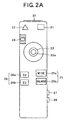
- FIG. 2A is a top plan view for showing the external structure of a remote controller relating to the present embodiment;
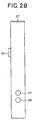
- FIG. 2B is a side view for showing the external structure of the remote controller relating to the present embodiment;
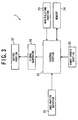
- FIG. 3 is a block diagram for showing the internal structure of the remote controller relating to the present embodiment;
- FIG. 4A is a view for showing one example of a bird's eye display on a display screen;
- FIG. 4B is a view for showing a view point of a bird's-eye view; and
- FIG. 5 is a flowchart for showing a processing to be carried out by the navigation apparatus based on the operation of the remote controller.
-
- There will be explained below a preferred embodiment of the present invention with reference to the drawings. In the present embodiment, a navigation system equipped with a remote controller of the present invention and mounted on a vehicle will be explained.
- At first, the overall structure of the navigation system relating to the embodiment will be explained with reference to FIG. 1. The navigation system shown in FIG. 1 includes a
remote controller 1 and anavigation apparatus 10. Thenavigation apparatus 10 includes a main controller 11, amap memory 12, aposition detector 13, aROM 14, aRAM 15, adisplay 16, aspeaker 17, and asignal receiver 18. Theremote controller 1 is an apparatus for transmitting a control signal according to infrared rays to thesignal receiver 18. - In the above structure, the
position detector 13 includes a vehicle speed sensor for detecting a move quantity of a vehicle, an azimuth sensor using a gyroscope or the like for detecting an azimuth change quantity of the vehicle, a GPS (Global Positioning System) receiver for receiving a wave from a GPS satellite, and detects a current position of the vehicle based on output signals from these units. - The
map memory 12 is a memory of a large memory capacity for storing road map data. A CD-ROM or a DVD-ROM is used for themap memory 12. The road map stored in themap memory 12 includes road data, name data, background data, etc. The current position of the vehicle detected by theposition detector 13 is collated with the road map data, and is corrected by a map matching processing or the like. - The
display 16 displays the map data in various ways under the instruction of the main controller 11. The current position of the vehicle is superimposed on the map data and is displayed as a car mark. Thisdisplay 16 is structured by, for example, a CRT, a liquid crystal display device, or the like. From thespeaker 17, guide information along the route of the vehicle is output in voice. - The main controller 11 controls the overall operation of the navigation system, and is structured by a CPU and the like. The main controller 11 reads out a control program stored in the
ROM 14 and executes the program, and carries out a processing by temporarily storing processing data in theRAM 15. Further, the main controller 11 reads out the map data from themap memory 12 and obtains current position data from theposition detector 13, to carry out various data correction processing and to control outputs to thedisplay 16 and thespeaker 17. - The
remote controller 1 is means for the user to set functions by manipulating various switches. Theremote controller 1 generates control signals and transmits these signals by infrared rays. Thesignal receiver 18 then receives the infrared rays, and the main controller 11 decides the control signal to carry out a desired setting. In the present embodiment, in addition to the operation by using various switches, an inclination detector of theremote controller 1 detects an inclination of the remote controller to generate a corresponding control signal. - The structure and functions of the
remote controller 1 will be explained next with reference to FIG. 2A, FIG. 2B and FIG. 3. FIG. 2A is a top plan view for showing theremote controller 1, FIG. 2B is a side view for showing theremote controller 1, and FIG. 3 is a view for showing the internal structure of theremote controller 1. - As shown in FIG. 2A and FIG. 2B, the
remote controller 1 is provided with various kinds of switches for the user to carry out a desired manipulation of thenavigation apparatus 10. More specifically, on the front surface of theremote controller 1, there are provided amenu switch 21, acurrent position switch 22, ajoy stick 23, a sensordirect switch 24, ascale change switch 25 and a view angle change-over switch 26. Afirst trigger switch 27 and asecond trigger switch 28 are provided on the side surface of theremote controller 1. The functions of these parts will be described later. - As shown in FIG. 3, the
remote controller 1 incorporates aninclination detector 31 for detecting an inclination angle of theremote controller 1 when the user inclines theremote controller 1. The user can manipulate theremote controller 1 by inclining it instead of using the above-described switches. - In FIG. 3, the
remote controller 1 includes theinclination detector 31, acontrol portion 32 for collectively controlling the overall operation of theremote controller 1, a manipulatingportion 33 corresponding to the above-described switches, amemory 34 for storing data necessary for the processing, apower source portion 35 such as a battery or the like for supplying power to theremote controller 1, asignal generator 36 for generating a control signal corresponding to the manipulation of the manipulatingportion 33, and anoutput portion 37 for irradiating infrared rays modulated based on the control signal. - The
inclination detector 31 detects a forward, backward or leftward or rightward inclination of theremote controller 1 along the longitudinal direction of the main body of theremote controller 1, and outputs a detection signal proportional to this inclination angle. In other words, when the user has inclined the main body of theremote controller 1 along a specific direction by holding the main body of theremote controller 1 in one hand, this enables a desired manipulation to be carried out such as the scroll of the map displayed on the display surface, for example. A detection signal corresponding to an inclination angle output from theinclination detector 31 is output to thecontrol portion 32, and is transmitted to thenavigation apparatus 10 from theoutput portion 37 through thesignal generator 36. - The relation between the inclination angle in the
inclination detector 31 and the control quantity of manipulation corresponding to this inclination angle may be set suitably. For example, the control quantity may be set variable in detail according to the inclination angle. Alternatively, the control may be carried out based on only three values in the horizontal status, the upward inclined status and the downward inclined status. - The range of the inclination angle of the
inclination detector 31 may be set free to some extent. However, it is not possible to take an extremely large range as it is restricted to within the range where infrared rays can reach thesignal receiver 18 of the navigation system at least from theoutput portion 37. - On the other hand, the user can carry out a desired manipulation by inclining the main body of the
remote controller 1 as described above while carrying out other manipulations with various switches as shown in FIG. 2A and FIG. 2B at the same time. In other words, when the user has depressed themenu switch 21, various menus necessary for the navigation are displayed on the display screen of thedisplay 16. When thecurrent position switch 22 is depressed, the above-described car mark for showing the current position of the vehicle is displayed on the display screen together with the map of the surrounding area. The view angle change-over switch 26 changes over a view point angle of the map displayed on the display screen. When a2D switch 26b is depressed, the view point angle is changed over to a top plan view, and when a3D switch 26a is depressed, the view point angle is changed over to a bird's eye view. Thescale change switch 25 is for enlarging or reducing the scale of the map on the display screen. When awide switch 25a is depressed, the scale of the map is reduced to display a wide area, and when an enlargeswitch 25b is depressed, the map is enlarged and a narrow area is displayed. - When the
joy stick 23 is tilted, the map on the display screen can be scrolled to a predetermined direction. In other words, when thejoy stick 23 is tilted forward, backward, or leftward or rightward, the map is scrolled in the tilted direction. While the joy stick is kept tilted, the map continues to scroll at a predetermined speed. A determining switch 23a is provided at the head of thejoy stick 23. This switch is depressed to determine a desired item selected from the above-described various menus of the navigation. - In the present embodiment, in addition to the above-described various switches and the
joy stick 23, as a manipulation of the inclination of the remote controller main body, it is also possible to change over the view point angle of the map on the display screen, in a similar manner to that of the view angle change-over switch 26. In other words, it is possible to display a top plan view of the map as viewed from the above and a bird's-eye view of the map as viewed from a slant angle by changing over between these views. This view point angle is changed by linking it to the size of a detection signal of theinclination detector 31. - There will be described below a case of changing over the view point angle of the map corresponding to the inclination angle when the
inclination detector 31 has been inclined upward or downward along the longitudinal direction of theremote controller 1, without taking into account changes in lateral directions of the map. - FIG. 4A and FIG. 4B are views for explaining one example of a bird's-eye view. A display screen shown in FIG. 4A corresponds to a bird's-eye view when the map is looked at from above the map at a view point angle of as shown in FIG. 4B. In this case, when the view point angle is 90 degrees, the above-described top plan view is obtained. When the upper part of the main body of the
remote controller 1 is inclined downward, the view point angle becomes smaller. On the other hand, when the upper part of the main body of theremote controller 1 is inclined upward, the view point angle becomes larger. With this arrangement, it is possible to move the view point of the map on the display screen linked with the inclination of the main body of theremote controller 1 with a sense of piloting an airplane. - Further, the function of the
inclination detector 31 is controlled by thefirst trigger switch 27 and thesecond trigger switch 28 provided on the side surface of theremote controller 1. Thefirst trigger switch 27 and thesecond trigger switch 28 function as the switching means of the present invention. In other words, it is possible to allocate functions such that when theremote controller 1 is inclined by depressing only thefirst trigger switch 27, the above-described change-over of the view point angle is carried out and that other function is allocated to thesecond trigger switch 28. For example, thesecond trigger switch 28 can be allocated with the function corresponding to the above-describedscale change switch 25 according to a detection signal of theinclination detector 31 when thesecond trigger switch 28 is depressed. Alternatively, thesecond trigger switch 28 can be allocated with the function of audio sound volume control having no relation with the navigation. As explained above, by providing the trigger switches 27 and 28, it is possible to prevent theremote controller 1 from being manipulated erroneously by inclination when it is not necessary to manipulate theremote controller 1. At the same time, it is possible to select a plurality of manipulations. - In the present embodiment, it is also possible to manipulate the
inclination detector 31 by using the sensordirect switch 24 in a similar manner. In other words, as shown in FIG. 2A, the sensordirect switch 24 is structured to be able to be moved forward or backward by the user. Corresponding to the forward or backward move of the sensordirect switch 24, it is possible to output a detection signal similar to that obtained when theremote controller 1 is inclined in upward or downward direction. Accordingly, the user can also change over the view point angle of the map on the display screen as described above by moving forward or backward the sensordirect switch 24. Thus, the user can select the method of manipulating theremote controller 1 according to the user's preference. It is also possible to use the conventional method of manipulating theremote controller 1. - The processing to be carried out in the navigation system based on the manipulation of the
remote controller 1 will be explained next with reference to a flowchart shown in FIG. 5. This processing is carried out according to the control program stored in theROM 14 in the main controller 11 of the navigation system main body. The explanation will be made of the case where a single manipulation depending on the inclination angle of theremote controller 1 is carried out or a combined manipulation with other manipulation is carried out. - When the processing has been started, at step S1, the inclination angle of the
remote controller 1 is detected. In other words, a detection signal corresponding to the inclination angle of theremote controller 1 is transmitted at a suitable timing. This transmitted detection signal reaches the main controller 11 from theoutput portion 37 of theremote controller 1 through thesignal receiver 18 of the navigation system. Therefore, the main controller 11 reads this detection signal and obtains the inclination angle. - At step S2, the main controller 11 makes a decision as to whether the
remote controller 1 is horizontal or is inclined, based on the inclination angle obtained at the step S1. When theremote controller 1 is horizontal as a result of the decision made (YES at the step S2), a manipulation depending on the inclination angle is not carried out. Therefore, the process then returns to the step S1, and a similar processing is repeated. On the other hand, when theremote controller 1 is inclined (NO at the step S2), the process proceeds to step S3. By determining a suitable threshold value, for example, it is possible to make a decision as to whether theremote controller 1 is horizontal or is inclined according to the relative size of the inclination angle as compared with the threshold value. - At the step S3, a decision is made as to whether the
first trigger switch 27 or thesecond trigger switch 28 has been depressed or not, based on the detection signal from theremote controller 1. When none of the trigger switches has been depressed as a result of the decision made (NO at the step S3), a manipulation depending on the inclination angle is not carried out. Therefore the process then returns to the step S1, and a similar processing is repeated. On the other hand, when thefirst trigger switch 27 or thesecond trigger switch 28 has been depressed (YES at the step S3), the process proceeds to step S4. - At the step S4, based on the detection signal from the
remote controller 1, a decision is made as to whether other manipulation has been carried out or not, that is, whether various kinds of switches have been depressed or thejoy stick 23 has been tilted or not. When no other manipulation has been carried out as a result of the decision made (NO at the step S4), the process proceeds to step S5 to carry out a single manipulation. On the other hand, when other manipulation has been carried out as a result of the decision made (YES at the step S4), the process proceeds to step S6 to carry out a combined manipulation. - At the step S5, a single manipulation depending on the inclination angle of the
remote controller 1 is carried out. When thefirst trigger switch 27 has been depressed in response to the decision made at the step S3, the view point angle of the map on the display screen is changed depending on the inclination angle. When thesecond trigger switch 28 has been depressed, a predetermined manipulation is carried out such as, for example, an enlargement or a reduction of the scale of the map depending on the inclination angle. - At the step S6, in addition to the manipulation depending on the inclination angle of the
remote controller 1, a combined manipulation depending on the manipulation of the switches and thejoy stick 23 decided at the step S4 is carried out. In other words, when thejoy stick 23 has been tilted, the map displayed on the display screen is scrolled to a predetermined direction together with the processing at the step S5. In this case, it is possible to add changes to the view point angle of the map or to reduce or enlarge the scale of the map, while scrolling the map to a desired direction on the display screen. - As explained above, according to the present embodiment, the user can carry out the manipulation of the
remote controller 1 such as the changes of the view point angle of the map on the display screen by only inclining theinclination detector 31 provided on theremote controller 1 while holding theremote controller 1 in one hand. Therefore, it is possible to improve the controllability of the navigation system. Particularly when the navigation system is mounted on the vehicle, it is very useful. Further, as the presence or absence of the manipulation of the inclination detector can be set and the object to be manipulated can be set by the trigger switches 27 and 28, it is possible to further improve the convenience. Furthermore, as it is possible to carry out a combined manipulation such as the scrolling of the map by tilting thejoy stick 23 and the depressing of other switches at the same time, a desired manipulation can be done promptly. - In the above-described embodiment, the explanation has been made of the case where the view point angle of the map on the display screen is changed over corresponding to the inclination angle of the
inclination detector 31 when thefirst trigger switch 27 has been depressed. However, it is also possible to allocate the control of the scrolling or the scale changes to the switch-over of the inclination angle of theinclination detector 31 Similarly, the controls allocated to the switch-over of the inclination angle of theinclination detector 31 when thesecond trigger switch 28 has been depressed, thejoy stick 23 and the sensordirect switch 24 respectively are not limited to those explained in the above-described embodiment. For example, it is possible to allocate the control of the view point angle of the map, or the scale changes to thejoy stick 23. - Further, it has been explained that the
first trigger switch 27 and thesecond trigger switch 28 are provided as switching means on theremote controller 1 of the above-described embodiment. However, the number of these switches is not limited. Depending on the using status of theremote controller 1, it is not necessary to provide trigger switches. Further, the present invention can also be applied to the case where thejoy stick 23 and the sensordirect switch 24 are not provided. - Further, in the above-described embodiment, the explanation has been made of the case where the navigation system is controlled by the
remote controller 1. However, this case is not limited, and it is also possible to use the remote control apparatus of the present invention to other devices. For example, the present invention can also be applied to the remote control apparatus to be used in the television apparatus or the video player. In this case, it is possible to control the adjustment of sound volume, the quick feeding and winding back of the object corresponding to the inclination angle of the remote control apparatus. - Further, in the above-described embodiment, for carrying out the manipulation depending on the inclination angle of the
remote controller 1, it is also possible to change the operation speed of the object to be manipulated according to the time period while the user is keeping theremote controller 1 inclined by depressing thefirst trigger switch 27 or thesecond trigger switch 28. For example, in the case of changing the view point angle of the map on the display screen, it may be so controlled that the move of the view point angle of the map becomes gradually faster with the lapse of time while theremote controller 1 is being kept inclined in the state that thefirst trigger switch 27 is being depressed. Alternatively, in the case of carrying out a quick feeding of a film of a video player, it may be so controlled that the speed of the quick feeding becomes gradually faster with the lapse of time when theremote controller 1 is being kept inclined in the state that thesecond trigger switch 28 is being depressed. With the above-described arrangement, the user can carry out a desired manipulation more promptly after a lapse of some time while it is possible to carry out a manipulation involving a fine adjustment at the beginning. As a result, it is possible to further improve the controllability. Such a function can be realized by appropriately changing the control signal supplied from theremote controller 1 to thenavigation apparatus 10 as infrared rays, according to a time period during which the inclination of theremote controller 1 is maintained.
Claims (16)
- A remote control apparatus (1) for transmitting a control signal for controlling an operation of an object (10) to be controlled to the object, characterised in that the remote control apparatus comprises:an inclination detector (31) for detecting an inclination of the remote control apparatus; andan output device (32, 36, 37) for outputting an inclination signal for indicating the inclination of the remote control apparatus as the control signal.
- The remote control apparatus (1) according to claim 1, further comprising a switching device (33) for changing over a control based on the inclination of the remote control apparatus to valid or invalid.
- A navigation system for a vehicle, comprising a navigation apparatus (10) for displaying a road map corresponding to road map data and a remote control apparatus (1) for controlling a display of the navigation apparatus, characterised in thatthe remote control apparatus (1) comprises an inclination detector (31) for detecting an inclination of the remote control apparatus, and an inclination signal output device (32, 36, 37) for outputting an inclination signal that indicates the inclination of the remote control apparatus to the navigation apparatus, andthe navigation apparatus (10) executes a display control of the road map according to the inclination of the remote control apparatus (1), based on the inclination signal.
- The navigation system according to claim 3, wherein the remote control apparatus (1) further comprises a switching device (33) for changing over a control based on the inclination of the remote control apparatus to valid or invalid.
- The navigation system according to claim 3, wherein the navigation apparatus (10) executes a control of a view point angle of a road map to be displayed according to the inclination of the remote control apparatus (1), based on the inclination signal.
- The navigation system according to claim 3, wherein the navigation apparatus (10) executes a control of scroll of the road map according to the inclination of the remote control apparatus (1), based on the inclination signal.
- The navigation system according to claim 3, wherein the navigation apparatus (10) executes a control of setting of a scale of the road map to be displayed according to the inclination of the remote control apparatus (1), based on the inclination signal.
- The navigation system according to claim 3, wherein the remote control apparatus (1) further comprises a joy stick (23) that can be tilted toward a plurality of directions, and a joy stick signal output device (32, 33, 36, 37) for outputting a joy stick signal to the navigation apparatus (10) according to a tilting of the joy stick.
- The navigation system according to claim 8, wherein the navigation apparatus (10) executes a control of a view point angle of the road map to be displayed according to the inclination of the remote control apparatus (1) based on the inclination signal, and executes a control of scroll of the rod map based on the joy stick signal.
- The navigation system according to claim 8, wherein the navigation apparatus (10) executes a control of a view point angle of the road map to be displayed according to the inclination of the remote control apparatus (1) based on the inclination signal, and executes a control of setting of a scale of the rod map to be displayed based on the joy stick signal.
- The navigation system according to claim 8, wherein the navigation apparatus (10) executes scroll of the road map according to the inclination of the remote control apparatus (1) based on the inclination signal, and executes a control of a view point angle of the rod map to be displayed based on the joy stick signal.
- The navigation system according to claim 8, wherein the navigation apparatus (10) executes scroll of the road map according to the inclination of the remote control apparatus (1) based on the inclination signal, and executes a control of setting of a scale of the rod map to be displayed based on the joy stick signal.
- The navigation system according to claim 8, wherein the navigation apparatus (10) executes a control of setting of a scale of the road map to be displayed according to the inclination of the remote control apparatus (1) based on the inclination signal, and executes a control of a view point angle of the rod map to be displayed based on the joy stick signal.
- The navigation system according to claim 8, wherein the navigation apparatus (10) executes a control of setting of a scale of the road map to be displayed according to the inclination of the remote control apparatus (1) based on the inclination signal, and executes a control of scroll of the rod map based on the joy stick signal.
- The navigation system according to any one of claims 3 through 14, wherein the remote control apparatus (1) further comprises a control switch, a switch signal output device (32, 33, 36, 37) for outputting a switch signal to the navigation apparatus (10) according to a manipulation of the control switch, and a selecting device (32, 33) for selecting an output of the inclination signal from the inclination signal output device and an output of the switch signal from the switch signal output device.
- The navigation system according to any one of claims 3 through 15, wherein the navigation apparatus (10) changes the inclination signal according to a time period during which the inclination of the remote control apparatus (1) is maintained.
Priority Applications (1)
| Application Number | Priority Date | Filing Date | Title |
|---|---|---|---|
| EP09006824.8A EP2085939B1 (en) | 1998-12-07 | 1999-12-06 | Remote controller and navigation system for vehicle |
Applications Claiming Priority (2)
| Application Number | Priority Date | Filing Date | Title |
|---|---|---|---|
| JP34752598A JP3651757B2 (en) | 1998-12-07 | 1998-12-07 | Remote control device and in-vehicle navigation device |
| JP34752598 | 1998-12-07 |
Related Child Applications (2)
| Application Number | Title | Priority Date | Filing Date |
|---|---|---|---|
| EP09006824.8A Division EP2085939B1 (en) | 1998-12-07 | 1999-12-06 | Remote controller and navigation system for vehicle |
| EP09006824.8 Division-Into | 2009-05-20 |
Publications (3)
| Publication Number | Publication Date |
|---|---|
| EP1035529A2 true EP1035529A2 (en) | 2000-09-13 |
| EP1035529A3 EP1035529A3 (en) | 2000-10-18 |
| EP1035529B1 EP1035529B1 (en) | 2013-04-24 |
Family
ID=18390823
Family Applications (2)
| Application Number | Title | Priority Date | Filing Date |
|---|---|---|---|
| EP19990309794 Expired - Lifetime EP1035529B1 (en) | 1998-12-07 | 1999-12-06 | Remote controller and navigation system for vehicle |
| EP09006824.8A Expired - Lifetime EP2085939B1 (en) | 1998-12-07 | 1999-12-06 | Remote controller and navigation system for vehicle |
Family Applications After (1)
| Application Number | Title | Priority Date | Filing Date |
|---|---|---|---|
| EP09006824.8A Expired - Lifetime EP2085939B1 (en) | 1998-12-07 | 1999-12-06 | Remote controller and navigation system for vehicle |
Country Status (2)
| Country | Link |
|---|---|
| EP (2) | EP1035529B1 (en) |
| JP (1) | JP3651757B2 (en) |
Cited By (2)
| Publication number | Priority date | Publication date | Assignee | Title |
|---|---|---|---|---|
| WO2007036818A1 (en) * | 2005-09-29 | 2007-04-05 | Koninklijke Philips Electronics N.V. | A remote control device and system |
| WO2009139010A1 (en) * | 2008-05-14 | 2009-11-19 | Sist&Matica S.R.L. | Remote control system |
Families Citing this family (4)
| Publication number | Priority date | Publication date | Assignee | Title |
|---|---|---|---|---|
| US8019514B2 (en) | 2007-02-28 | 2011-09-13 | Caterpillar Inc. | Automated rollover prevention system |
| JP5119389B2 (en) * | 2008-05-26 | 2013-01-16 | Toa株式会社 | Portable terminal device for audio equipment |
| US9329051B1 (en) | 2014-11-21 | 2016-05-03 | Honda Motor Co. Ltd. | Navigation system and method to scroll to user selected point of interests (POIs) |
| CN115331418B (en) * | 2022-08-17 | 2024-04-09 | 冠捷显示科技(武汉)有限公司 | Remote controller based on gesture triggering function and control method thereof |
Citations (4)
| Publication number | Priority date | Publication date | Assignee | Title |
|---|---|---|---|---|
| US5030955A (en) * | 1989-07-25 | 1991-07-09 | Nokia Unterhaltungselektronik | Remote control transmitter |
| US5453758A (en) * | 1992-07-31 | 1995-09-26 | Sony Corporation | Input apparatus |
| US5606316A (en) * | 1995-04-04 | 1997-02-25 | Pioneer Electronic Corporation | Signal input system for an electronic equipment |
| EP0875730A1 (en) * | 1997-05-02 | 1998-11-04 | Pioneer Electronic Corporation | Device for and method of displaying map information for vehicle navigation apparatus |
Family Cites Families (1)
| Publication number | Priority date | Publication date | Assignee | Title |
|---|---|---|---|---|
| KR870007713A (en) * | 1986-02-07 | 1987-09-21 | 케네디 멜빈 | Improved remote control toy car |
-
1998
- 1998-12-07 JP JP34752598A patent/JP3651757B2/en not_active Expired - Lifetime
-
1999
- 1999-12-06 EP EP19990309794 patent/EP1035529B1/en not_active Expired - Lifetime
- 1999-12-06 EP EP09006824.8A patent/EP2085939B1/en not_active Expired - Lifetime
Patent Citations (4)
| Publication number | Priority date | Publication date | Assignee | Title |
|---|---|---|---|---|
| US5030955A (en) * | 1989-07-25 | 1991-07-09 | Nokia Unterhaltungselektronik | Remote control transmitter |
| US5453758A (en) * | 1992-07-31 | 1995-09-26 | Sony Corporation | Input apparatus |
| US5606316A (en) * | 1995-04-04 | 1997-02-25 | Pioneer Electronic Corporation | Signal input system for an electronic equipment |
| EP0875730A1 (en) * | 1997-05-02 | 1998-11-04 | Pioneer Electronic Corporation | Device for and method of displaying map information for vehicle navigation apparatus |
Cited By (3)
| Publication number | Priority date | Publication date | Assignee | Title |
|---|---|---|---|---|
| WO2007036818A1 (en) * | 2005-09-29 | 2007-04-05 | Koninklijke Philips Electronics N.V. | A remote control device and system |
| WO2009139010A1 (en) * | 2008-05-14 | 2009-11-19 | Sist&Matica S.R.L. | Remote control system |
| US8358194B2 (en) | 2008-05-14 | 2013-01-22 | Sist & Matica S.R.L. | Remote control system |
Also Published As
| Publication number | Publication date |
|---|---|
| JP3651757B2 (en) | 2005-05-25 |
| EP1035529B1 (en) | 2013-04-24 |
| EP1035529A3 (en) | 2000-10-18 |
| EP2085939A2 (en) | 2009-08-05 |
| EP2085939B1 (en) | 2013-05-01 |
| EP2085939A3 (en) | 2010-01-06 |
| JP2000172989A (en) | 2000-06-23 |
Similar Documents
| Publication | Publication Date | Title |
|---|---|---|
| JP5028038B2 (en) | In-vehicle display device and display method for in-vehicle display device | |
| US8108137B2 (en) | Map scrolling method and navigation terminal | |
| US7788028B2 (en) | Navigation system | |
| US7221364B2 (en) | Image generating apparatus, image generating method, and computer program | |
| JP2008304325A (en) | Navigation device and map scrolling processing method | |
| EP1491406A1 (en) | In-car remote control device and method | |
| EP2085939B1 (en) | Remote controller and navigation system for vehicle | |
| JP2004117830A (en) | Navigation device | |
| JP2003097964A (en) | Input control device | |
| JP2004117294A (en) | Navigation system, method, and program | |
| JP2000241170A (en) | Scrolling method and navigation device | |
| JP4343070B2 (en) | Multi monitor system | |
| JPH02140788A (en) | Map display method | |
| JP3842522B2 (en) | Map display method and apparatus | |
| JP2000074677A (en) | Method and device for navigation | |
| JPH10148535A (en) | Map information transfer device | |
| JP2005308411A (en) | In-vehicle information terminal, and road map display method | |
| JPH07311049A (en) | Navigation system | |
| JP2000234935A (en) | Navigation device | |
| US20090160695A1 (en) | Remote control apparatus | |
| JP2567170B2 (en) | Current position display of mobile | |
| JP2005181572A (en) | Map display apparatus and map display method | |
| KR0153235B1 (en) | Handle key control apparatus for car navigation system | |
| JP4082969B2 (en) | Navigation device, method and program | |
| JP2005267450A (en) | Information processing device, its control method and program |
Legal Events
| Date | Code | Title | Description |
|---|---|---|---|
| PUAI | Public reference made under article 153(3) epc to a published international application that has entered the european phase |
Free format text: ORIGINAL CODE: 0009012 |
|
| PUAL | Search report despatched |
Free format text: ORIGINAL CODE: 0009013 |
|
| AK | Designated contracting states |
Kind code of ref document: A2 Designated state(s): DE FR GB |
|
| AX | Request for extension of the european patent |
Free format text: AL;LT;LV;MK;RO;SI |
|
| AK | Designated contracting states |
Kind code of ref document: A3 Designated state(s): AT BE CH CY DE DK ES FI FR GB GR IE IT LI LU MC NL PT SE |
|
| AX | Request for extension of the european patent |
Free format text: AL;LT;LV;MK;RO;SI |
|
| 17P | Request for examination filed |
Effective date: 20010108 |
|
| AKX | Designation fees paid |
Free format text: DE FR GB |
|
| RAP1 | Party data changed (applicant data changed or rights of an application transferred) |
Owner name: PIONEER CORPORATION |
|
| GRAP | Despatch of communication of intention to grant a patent |
Free format text: ORIGINAL CODE: EPIDOSNIGR1 |
|
| RIN1 | Information on inventor provided before grant (corrected) |
Inventor name: SATO, NAOKI, |
|
| GRAS | Grant fee paid |
Free format text: ORIGINAL CODE: EPIDOSNIGR3 |
|
| GRAA | (expected) grant |
Free format text: ORIGINAL CODE: 0009210 |
|
| AK | Designated contracting states |
Kind code of ref document: B1 Designated state(s): DE FR GB |
|
| REG | Reference to a national code |
Ref country code: GB Ref legal event code: FG4D |
|
| REG | Reference to a national code |
Ref country code: DE Ref legal event code: R096 Ref document number: 69944721 Country of ref document: DE Effective date: 20130620 |
|
| REG | Reference to a national code |
Ref country code: GB Ref legal event code: 746 Effective date: 20130701 |
|
| REG | Reference to a national code |
Ref country code: DE Ref legal event code: R086 Ref document number: 69944721 Country of ref document: DE Effective date: 20130712 |
|
| PLBE | No opposition filed within time limit |
Free format text: ORIGINAL CODE: 0009261 |
|
| STAA | Information on the status of an ep patent application or granted ep patent |
Free format text: STATUS: NO OPPOSITION FILED WITHIN TIME LIMIT |
|
| 26N | No opposition filed |
Effective date: 20140127 |
|
| REG | Reference to a national code |
Ref country code: DE Ref legal event code: R084 Ref document number: 69944721 Country of ref document: DE Effective date: 20140319 |
|
| REG | Reference to a national code |
Ref country code: DE Ref legal event code: R097 Ref document number: 69944721 Country of ref document: DE Effective date: 20140127 |
|
| REG | Reference to a national code |
Ref country code: FR Ref legal event code: PLFP Year of fee payment: 17 |
|
| REG | Reference to a national code |
Ref country code: FR Ref legal event code: PLFP Year of fee payment: 18 |
|
| REG | Reference to a national code |
Ref country code: FR Ref legal event code: PLFP Year of fee payment: 19 |
|
| PGFP | Annual fee paid to national office [announced via postgrant information from national office to epo] |
Ref country code: DE Payment date: 20181120 Year of fee payment: 20 |
|
| PGFP | Annual fee paid to national office [announced via postgrant information from national office to epo] |
Ref country code: GB Payment date: 20181205 Year of fee payment: 20 Ref country code: FR Payment date: 20181121 Year of fee payment: 20 |
|
| REG | Reference to a national code |
Ref country code: DE Ref legal event code: R071 Ref document number: 69944721 Country of ref document: DE |
|
| REG | Reference to a national code |
Ref country code: GB Ref legal event code: PE20 Expiry date: 20191205 |
|
| PG25 | Lapsed in a contracting state [announced via postgrant information from national office to epo] |
Ref country code: GB Free format text: LAPSE BECAUSE OF EXPIRATION OF PROTECTION Effective date: 20191205 |