EP1033848A1 - Proxy server supporting IP quality of service - Google Patents
Proxy server supporting IP quality of service Download PDFInfo
- Publication number
- EP1033848A1 EP1033848A1 EP99301429A EP99301429A EP1033848A1 EP 1033848 A1 EP1033848 A1 EP 1033848A1 EP 99301429 A EP99301429 A EP 99301429A EP 99301429 A EP99301429 A EP 99301429A EP 1033848 A1 EP1033848 A1 EP 1033848A1
- Authority
- EP
- European Patent Office
- Prior art keywords
- quality
- service
- network
- terminal
- session
- Prior art date
- Legal status (The legal status is an assumption and is not a legal conclusion. Google has not performed a legal analysis and makes no representation as to the accuracy of the status listed.)
- Granted
Links
Images


Classifications
-
- H—ELECTRICITY
- H04—ELECTRIC COMMUNICATION TECHNIQUE
- H04L—TRANSMISSION OF DIGITAL INFORMATION, e.g. TELEGRAPHIC COMMUNICATION
- H04L12/00—Data switching networks
- H04L12/28—Data switching networks characterised by path configuration, e.g. LAN [Local Area Networks] or WAN [Wide Area Networks]
-
- H—ELECTRICITY
- H04—ELECTRIC COMMUNICATION TECHNIQUE
- H04L—TRANSMISSION OF DIGITAL INFORMATION, e.g. TELEGRAPHIC COMMUNICATION
- H04L47/00—Traffic control in data switching networks
- H04L47/70—Admission control; Resource allocation
- H04L47/72—Admission control; Resource allocation using reservation actions during connection setup
- H04L47/724—Admission control; Resource allocation using reservation actions during connection setup at intermediate nodes, e.g. resource reservation protocol [RSVP]
-
- H—ELECTRICITY
- H04—ELECTRIC COMMUNICATION TECHNIQUE
- H04L—TRANSMISSION OF DIGITAL INFORMATION, e.g. TELEGRAPHIC COMMUNICATION
- H04L47/00—Traffic control in data switching networks
- H04L47/70—Admission control; Resource allocation
-
- H—ELECTRICITY
- H04—ELECTRIC COMMUNICATION TECHNIQUE
- H04L—TRANSMISSION OF DIGITAL INFORMATION, e.g. TELEGRAPHIC COMMUNICATION
- H04L47/00—Traffic control in data switching networks
- H04L47/70—Admission control; Resource allocation
- H04L47/80—Actions related to the user profile or the type of traffic
- H04L47/805—QOS or priority aware
-
- H—ELECTRICITY
- H04—ELECTRIC COMMUNICATION TECHNIQUE
- H04L—TRANSMISSION OF DIGITAL INFORMATION, e.g. TELEGRAPHIC COMMUNICATION
- H04L67/00—Network arrangements or protocols for supporting network services or applications
- H04L67/50—Network services
- H04L67/56—Provisioning of proxy services
-
- H—ELECTRICITY
- H04—ELECTRIC COMMUNICATION TECHNIQUE
- H04L—TRANSMISSION OF DIGITAL INFORMATION, e.g. TELEGRAPHIC COMMUNICATION
- H04L67/00—Network arrangements or protocols for supporting network services or applications
- H04L67/50—Network services
- H04L67/56—Provisioning of proxy services
- H04L67/562—Brokering proxy services
-
- H—ELECTRICITY
- H04—ELECTRIC COMMUNICATION TECHNIQUE
- H04L—TRANSMISSION OF DIGITAL INFORMATION, e.g. TELEGRAPHIC COMMUNICATION
- H04L69/00—Network arrangements, protocols or services independent of the application payload and not provided for in the other groups of this subclass
- H04L69/30—Definitions, standards or architectural aspects of layered protocol stacks
- H04L69/32—Architecture of open systems interconnection [OSI] 7-layer type protocol stacks, e.g. the interfaces between the data link level and the physical level
- H04L69/322—Intralayer communication protocols among peer entities or protocol data unit [PDU] definitions
- H04L69/329—Intralayer communication protocols among peer entities or protocol data unit [PDU] definitions in the application layer [OSI layer 7]
Definitions
- the present invention relates to the support of quality of service (QoS) requirements in Internet protocol (IP) packet routing.
- QoS quality of service
- IP Internet protocol
- IP internet protocol
- QoS quality of service
- RSVP Resource Reservation Protocol
- IP Integrated Services Model
- IETF Integrated Services Model
- IntServ defines two classes of services.
- the Controlled Load Class provides traffic delivery in the same way as when the network is unloaded ("better than best delivery").
- the Guaranteed QoS Service Class delivers traffic for applications with a bandwidth guarantee and delay bound.
- IntServ requires QoS capable nodes and a signaling protocol to communicate QoS requirements between applications and nodes and between nodes.
- RSVP is the QoS signaling protocol used by IntServ. RSVP provides receivers QoS requests to all router nodes along the transit path of the traffic, maintains the soft-state (Path/Reservation states), and results in resources being reserved in each router.
- RSVP/IntServ quality of service For RSVP/IntServ quality of service to operate, the flow identification information must be in a fixed location in the IP packet.
- An RSVP session is configured by the host terminals exchanging so-called Path and Reservation messages prior to data transmission.
- each host terminal must therefore have the functionality to configure the necessary messages and recognise quality of service requests corresponding to an RSVP session.
- RSVP implementations are platform and application dependent. Terminals include system specific RSVP daemons and/or RSVP API embedded in the applications. The platform and application dependency of existing RSVP implementations leads to a limited use of RSVP in some operating systems and those applications which are RSVP incapable..
- a method of configuring a quality of service session between terminals in different networks capable of supporting IP communication comprising: providing means, in at least one of the networks, associated with at least one terminal in that network and for configuring a quality of service session between that one terminal and a terminal in another network.
- the present invention is generally applicable to any quality of service session which utilises request and reply messages between two terminals for configuring a quality of service session.
- the quality of service session may be configured responsive to a quality of service request from the at least one terminal.
- the quality of service request may be indicative of the quality of service to be supported.
- the quality of service request may specify exactly the quality of service to be supported.
- the quality of service request may indicate the nature of the data to be transmitted once the quality of service session is established.
- the quality of service session may be an RSVP session and a Path message is generated by the means responsive to the quality of service request.
- the at least one terminal may receive a confirmation signal from the means indicating that the quality of service session has been configured.
- the quality of service session may be an RSVP session and the means generates the confirmation signal responsive to a Reservation message.
- a quality of service indication signal may be generated to the at least one terminal responsive to initiation of a quality of service session.
- the means may complete configuration of the quality of service session responsive to a quality of service response signal from the at least one terminal.
- the quality of service session may be an RSVP session and the initiation of the quality of service session is indicated by a Path message, and the configuration of the quality of service session is completed by receipt of a Reservation message.
- the present invention also provides a network having at least one terminal capable of supporting IP communication a means associated with the at least one terminal, for configuring a quality of service session between the at least one terminal and a terminal in another network.
- the means is preferably a proxy server.
- FIG. 1 there is shown a typical network set-up in which means for supporting quality-of-service (QoS) between host terminals is supported in accordance with the present invention.
- QoS quality-of-service
- a first network 2 includes a plurality of host terminals 40 all connected to a first network proxy server FN PS 42.
- a second network 4 also includes a plurality of host terminals 44 connected to a second network proxy server SN PS 46. Communication between host terminals in the respective networks is made by establishing interconnection via a plurality of routing switches 12.
- a particular second network host terminal 44a is connected to the second network proxy server 46 via a network link 62.
- a particular host terminal 40a in the first network is connected to the first network proxy server 42 via a network link 70.
- the second network proxy server 46 connects to one of the plurality of routing switches 12b via network link 64.
- the first network proxy server connects to one of the routing switches 12c via network link 68.
- the two routing switches are connected via network link 66.
- IP data packet transmitted between networks comprises an IP header 30, and an IP payload 22.
- the IP payload 22 is the information portion of the message.
- the IP header 30, shown in Figure 2(b) includes a source address portion 16, a destination address portion 18, and a protocol ID portion 20.
- the IP header 30 contains other fields which are not shown in Figure 3(b).
- the IP payload 32 includes a source port number 34 and a destination port number 36. Again, the IP payload includes other fields.
- the source address 16 is the IP address of the host terminal from which the IP data packet is sent (i.e. the second network host terminal 44a), and the destination address 18 is the address of the host terminal to which the IP data packet is to be sent.
- the source port number 34 is the port number used by an application at the source host terminal associated with the IP data packet 14.
- the destination port number is the port number used by an application of the destination host terminal to which the IP data packet 14 is being sent.
- the protocol ID 20 is one of the indications of the quality of service to be supported in transmitting the IP packet from the source applications to the destination applications.
- the destination and source addresses are used by routing switches to route the IP data packet to its destination.
- the protocol ID 20 is used together with the source and destination addresses 16 and 18, plus the communication port numbers of end applications (i.e. the source port number 34 and the destination port number 36) for differentiating flows and imposing the necessary QoS control.
- the QoS control imposed on the data traffic flows at the intermediate routers is system dependent. For example, it can be the so-called WFQ (Weighted Fair Queuing) or CBQ (Class Based Queuing). They are not standard and vendor specific but usually independent of the actual user's protocol ID.
- IntSer/RSVP The IETF's IntSer/RSVP standard is defined to provide a QoS specification and a signaling mechanism but not a QoS control mechanism. Intserve/RSVP is independent of the actual QoS control mechanisms, such as WFQ, CBQ etc.
- the status based on which QoS control is performed is set up in the routing switches prior to data transmission by means of the specific quality of service signaling protocol, e.g. RSVP.
- the technique for establishing a quality of service session, and particularly an RSVP session, between two host terminals according to the present invention will now be described with the aid of the flow diagram of Figure 2.
- the second network host terminal 44a initiates a communication with the host terminal 40a.
- the second network host terminal 44a initiating a quality of service session sends a quality of service request on network link 62 to the second network proxy server 46.
- the quality of service request may be implicit or explicit.
- An explicit quality of service request from the host terminal specifies an exact quality of service requirement.
- An explicit quality of service request can be provided only by a host terminal which has the functionality to support the explicit statement of a particular quality of service.
- An implicit quality of service request from the host terminal specifies only the nature of the transmission to be made. For example, an implicit quality of service request may indicate that the data to be sent is video data encoded using certain video codec. The proxy server then determines the appropriate quality of service in dependence on the indication of the type of data.
- the second network proxy server in a step 52, then sends a standard RSVP Path message.
- the Path message is communicated to the first network proxy server 18 associated with the host terminal with which the second network host terminal wants to communicate via the routing switches 12b and 12c.
- the IP packets of the messages used in an RSVP session do not have the format shown in Figures 3(a) to 3(c).
- the IP packets of Figures 3(a) to 3(c) are IP packets of data messages.
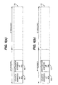
- the IP packets 70 of the Path message, as shown in Figure 4(a) have a source address 78 corresponding to the address of the second network host terminal 44a, and a destination address 80 corresponding to the address of the host terminal 40a in the first network (the host terminals home address).
- the IP packets of the Path message additionally include other flow identification information in the payload of the IP packets.
- One skilled in the art will be familiar with the other flow identification information.
- the Path message is sent out by the second network proxy server.
- the IP packets of the Path message are routed, in a conventional manner (based on the source and destination addresses) to the routing switch 12b.
- routing switches 12b,12c support quality of service, then they extract the flow identification information in the IP payload of the Path message IP packets, and store this flow identification information.
- This flow identification information includes: the source address, the destination address, the source port number, the destination port number, and the protocol ID which will be included in all IP data packets transmitted from the source to the destination after the quality of service session has been set up.
- the routing switches 12b,12c route the IP packets of the Path message to another routing switch, and then additionally stores with the flow identification information extracted from the IP packet, the address of the routing switch to which it sent the message (the next hop) and the address of the routing switch from which it received the message (the previous hop).
- the IP packets may reach the first network via two routing switches 12b,12c, in practice the IP packets may reach the first network via a larger plurality of routing switches, and each routing switch stores the flow identification information extracted from the IP packets of the Path message, together with the identity of the routing switch from which the IP packet was sent and the routing switch to which the IP packet was sent.
- IP packets of the Path message travel from the second network host terminal to the first network through the routing network.
- Each routing switch retains the address of the previous hop from which the IP packet was sent together with the next hop to which the IP packet was sent, and additionally the flow identification information for the IP packet.
- the routing switches also process the other traffic related information in the Path message, the nature of which is not relevant to a discussion of the present invention.
- each routing switch (provided it supports RSVP quality of service) retrieves the flow identification information from the fixed locations of the IP packets of the Path message and stores them in memory, together with the addresses of the next and previous hops.
- the flow identification information in the IP packets helps to uniquely identify a message flow, so that all IP packets associated with that message flow can be routed from the source to the destination through the exact same network path.
- the first network proxy server 42 receives the Path message, and in a step 54, sends a quality of service indication signal to the host terminal 40a on line 70, indicating the quality of service requested by the second network host terminal 44a. If the quality of service level is acceptable to the host terminal 40a, the host terminal sends a quality of service response by way of acknowledgement to the first network proxy server 42 in a step 56 on line 70.
- a step 58 the first network proxy server than sends a Reservation message to the second network proxy server 20, confirming the quality of service session.
- the Reservation message follows the identical route to the Path message (in reverse).
- the general format of the Reservation message 77 sent back by the first network proxy server is illustrated in Figure 4(b).
- the source address 115 is the host terminal's 40a address
- the destination address 117 is the second network host terminal's 44a address and the correct correlation exists between the source and destination addresses of the Path and Reservation messages in the RSVP session, such that the RSVP session is supported.
- the IP packets of a Reservation message are transmitted hop-by-hop back along the identical network path as the IP packets of the Path message.
- the source and destination addresses of the IP packets of the Reservation messages are actually the next and previous hops.
- the value of the source and destination addresses is thus determined dynamically as the Reservation messages transit through the path.
- the structure of the IP packets 77 of the Reservation message shown in Figure 4(b) is actually representative of the transport layer of the Reservation messages.
- the structure shown in Figure 4(b) illustrates the general concept of a Reservation message, that is the originating source address and the ultimate destination address.
- This analysis of the Reservation message is somewhat artificial, but serves to best illustrate the principle of RSVP for the purposes of this description. It should be noted that the example described herein utilises standard RSVP. No change to the standard RSVP is envisaged or proposed.
- the flow identification information in the IP packets of the Reservation message is retrieved from the memory of each routing switch as the IP packets arrive at the routing switches.
- the routing switches retrieve from their memories the Path information for the particular message flow, and send the IP packets to the previous hop indicated by the stored hop information.
- the Reservation message follows the identical route to the Path message (in reverse) via lines 68, 66 and 64.
- the second network proxy server receives the Reservation message and sends a quality of service confirmation message on line 62 by way of acknowledgement to the second network host terminal 14a, indicating that the quality of service session has been set up. This is indicated by step 60 in Figure 2.
- IP data packets do not go through either the second network proxy server or the first network proxy server.
- the IP packets go directly from the second network host terminal 44a to the host terminal 40a (and vice versa) through the routing network comprising the routing switches 12 following the network path determined by the flow identification information and configured during the quality of service session set-up.
- the proxy servers can provide quality of service sessions, such as RSVP Path and Reservation messages, for those terminals which have no ability of their own to facilitate such sessions.
- These terminals may be terminals which have no quality of service session capability at all.
- these terminals may have limited quality of service session capability, and the provision of a proxy server enables the quality of service session which can be supported by such terminals to become independent of the terminals capability. Even for those terminals which have extensive quality of service session capability, the provision of the proxy server enables the terminal to be relieved of processing tasks.
- Each host terminal which requires quality of service provision in a network needs to be aware of the existence of a proxy server in the network. That is, there must be a process by which the host terminals can discover proxy servers. There are effectively two ways this can happen. In a first way, host terminals in the network broadcast a server-soliciting message (SSM). A proxy server in the network responds by sending back to the host terminal a server response message (SRM). In a second way, the proxy server in a network broadcasts a client request message (CRQM) to the local network. Responsive thereto, host terminals (which can be considered to be proxy server clients) send back a client registration message (CRGM).
- SSM server-soliciting message
- SRM server response message
- CQM client request message
- proxy servers in the networks is registered by host terminals in the networks in a similar way as the presence of agents (home agents, foreign agents) is currently registered in standard mobile IP.
- agents home agents, foreign agents
- the implementation of the technique for nodes to register with proxy servers will be within the scope of one skilled in the art.
- a proxy server may be provided in only one network, the functionality for setting up a quality of service session being provided by the host terminals themselves in one or more networks.
- the example of Figure 1 shows both the first network and the second network including proxy servers and an RSVP session being established using the two respective proxy servers, in practice only one of the two proxy servers (either the first network proxy server or the second network proxy server) may be provided, and the quality of service session established between the one of the proxy terminals and a terminal. It is not essential that the one of the terminals requesting the quality of service session is provided with a proxy server, or that the one of the terminals responsive to the quality of service session is provided with a proxy server.
- the proxy server may be associated with only some of the host terminals in a particular network. Several proxy servers may be provided in one network to support different host terminals.
- the proxy server complies with the IETF RFC 2205, and other RSVP IntServ related RFCs, and inter-operates with all current publicly available RSVP implementations.
- the application and platform independence provided by the proxy server supports all applications including live video/audio on all available operating platforms, including Sun Solaris, Linux and Windows 95/NT.
- the application and platform independence provided by the RSVP proxy servers is due to the removal of the RSVP functionality of the nodes/terminals themselves. It will be appreciated that even terminals having RSVP capability may operate with an RSVP proxy server to enable application/platform in dependency and to relieve processing burden.
- the proxy server alleviates the problem of computational overhead due to the RSVP messages processing for those terminals that have limited processing power and/or a short battery life.
- the proxy server can operate as a front-end agent to provide computation-intensive processing tasks for initiating RSVP signaling and interacting with the RSVP capable network nodes and elements for quality of service provisioning.
- the invention has been described herein with reference to a particular example of an RSVP quality of service session which utilises Path and Reservation messages. However, the invention is more generally applicable to any quality of service session which utilises request and reply messages between two terminals for configuring a quality of service session.
Abstract
Description
- The present invention relates to the support of quality of service (QoS) requirements in Internet protocol (IP) packet routing.
- Current internet protocol (IP) technology enables a level of quality of service to be maintained in the transmission of IP packets between host terminals in different networks. Typically, the quality of service is maintained by the routing switches extracting flow identification information from IP packets. The quality of service (QoS) provisions proposed to be used in the Internet are defined by standards, and in IP one known standard for quality of service signaling is called RSVP. RSVP (Resource Reservation Protocol) is used in the Integrated Services Model (IntServ) quality of service framework defined by IETF. The Integrated Services Model was designed to provide special handling for certain types of traffic, provide mechanisms for applications to choose between multiple levels of delivery services for its traffic, and to provide signaling for quality of service parameters at Layer 3 in the OSI RM.
- IntServ defines two classes of services. The Controlled Load Class provides traffic delivery in the same way as when the network is unloaded ("better than best delivery"). The Guaranteed QoS Service Class delivers traffic for applications with a bandwidth guarantee and delay bound.
- IntServ requires QoS capable nodes and a signaling protocol to communicate QoS requirements between applications and nodes and between nodes.
- RSVP is the QoS signaling protocol used by IntServ. RSVP provides receivers QoS requests to all router nodes along the transit path of the traffic, maintains the soft-state (Path/Reservation states), and results in resources being reserved in each router.
- For RSVP/IntServ quality of service to operate, the flow identification information must be in a fixed location in the IP packet. An RSVP session is configured by the host terminals exchanging so-called Path and Reservation messages prior to data transmission.
- To enable the quality of service control across the transit path between peer host terminals, each host terminal must therefore have the functionality to configure the necessary messages and recognise quality of service requests corresponding to an RSVP session.
- One problem with existing RSVP implementations is that they are platform and application dependent. Terminals include system specific RSVP daemons and/or RSVP API embedded in the applications. The platform and application dependency of existing RSVP implementations leads to a limited use of RSVP in some operating systems and those applications which are RSVP incapable..
- It is therefore an object of the present invention to provide a technique whereby the requirement to set up a particular quality of service session between host terminals in different networks can be simply and widely provided.
- According to the present invention there is provided a method of configuring a quality of service session between terminals in different networks capable of supporting IP communication, the method comprising: providing means, in at least one of the networks, associated with at least one terminal in that network and for configuring a quality of service session between that one terminal and a terminal in another network.
- The present invention is generally applicable to any quality of service session which utilises request and reply messages between two terminals for configuring a quality of service session.
- There is thus provided a technique for configuring a quality of service session which is both platform and application independent. By providing a dedicated means for establishing quality of service sessions, then current and future quality of service signaling incapable host terminals can have a quality of service session set-up and thus their quality of service control enabled across the transmit path to their communication peers.
- The requirements for complicated and intensive computing as induced in many quality of service control signaling and control mechanisms, and strain on battery power for wireless/mobile terminals, are avoided. The quality of service session may be configured responsive to a quality of service request from the at least one terminal. The quality of service request may be indicative of the quality of service to be supported. The quality of service request may specify exactly the quality of service to be supported. The quality of service request may indicate the nature of the data to be transmitted once the quality of service session is established. The quality of service session may be an RSVP session and a Path message is generated by the means responsive to the quality of service request. The at least one terminal may receive a confirmation signal from the means indicating that the quality of service session has been configured. The quality of service session may be an RSVP session and the means generates the confirmation signal responsive to a Reservation message.
- A quality of service indication signal may be generated to the at least one terminal responsive to initiation of a quality of service session. The means may complete configuration of the quality of service session responsive to a quality of service response signal from the at least one terminal. The quality of service session may be an RSVP session and the initiation of the quality of service session is indicated by a Path message, and the configuration of the quality of service session is completed by receipt of a Reservation message.
- The present invention also provides a network having at least one terminal capable of supporting IP communication a means associated with the at least one terminal, for configuring a quality of service session between the at least one terminal and a terminal in another network.
- The means is preferably a proxy server.
-
- Figure 1 illustrates an example network set-up in which each network is provided with a proxy server in accordance with the invention;
- Figure 2 shows a flow diagram illustrating the main steps for setting up a quality of service session in the network of Figure 1;
- Figure 3 illustrates the message packet format according to the internet protocol (IP); and
- Figures 4(a) and 4(b) represent the general format of Path and Reservation messages for configuring an RSVP quality of service session.
-
- Referring to Figure 1 there is shown a typical network set-up in which means for supporting quality-of-service (QoS) between host terminals is supported in accordance with the present invention.
- A
first network 2 includes a plurality ofhost terminals 40 all connected to a first network proxy server FN PS 42. Asecond network 4 also includes a plurality ofhost terminals 44 connected to a second network proxy server SNPS 46. Communication between host terminals in the respective networks is made by establishing interconnection via a plurality of routing switches 12. A particular secondnetwork host terminal 44a is connected to the secondnetwork proxy server 46 via anetwork link 62. Aparticular host terminal 40a in the first network is connected to the firstnetwork proxy server 42 via anetwork link 70. The secondnetwork proxy server 46 connects to one of the plurality ofrouting switches 12b vianetwork link 64. The first network proxy server connects to one of therouting switches 12c vianetwork link 68. The two routing switches are connected vianetwork link 66. - In network systems which require a specific quality of service a quality of service session must be configured between the host terminals at each end of the communication link before the transmission of IP packets takes place. The general format of IP data packets is shown in Figures 3(a) to 3(c). An IP data packet transmitted between networks, generally designated by
reference numeral 14 and illustrated in Figure 3(a), comprises anIP header 30, and anIP payload 22. TheIP payload 22 is the information portion of the message. TheIP header 30, shown in Figure 2(b), includes asource address portion 16, adestination address portion 18, and aprotocol ID portion 20. TheIP header 30 contains other fields which are not shown in Figure 3(b). Referring to Figure 3(c), theIP payload 32 includes asource port number 34 and adestination port number 36. Again, the IP payload includes other fields. - The
source address 16 is the IP address of the host terminal from which the IP data packet is sent (i.e. the secondnetwork host terminal 44a), and thedestination address 18 is the address of the host terminal to which the IP data packet is to be sent. Thesource port number 34 is the port number used by an application at the source host terminal associated with theIP data packet 14. The destination port number is the port number used by an application of the destination host terminal to which theIP data packet 14 is being sent. - In addition to other uses, the
protocol ID 20 is one of the indications of the quality of service to be supported in transmitting the IP packet from the source applications to the destination applications. As will be appreciated by one familiar with the art, and discussed further hereinafter, the destination and source addresses are used by routing switches to route the IP data packet to its destination. - When the the routers or routing switches support quality of service (QoS), in some QoS control provisions, such as RSVP and IntServ, the
protocol ID 20 is used together with the source and destination addresses 16 and 18, plus the communication port numbers of end applications (i.e. thesource port number 34 and the destination port number 36) for differentiating flows and imposing the necessary QoS control. - The QoS control imposed on the data traffic flows at the intermediate routers is system dependent. For example, it can be the so-called WFQ (Weighted Fair Queuing) or CBQ (Class Based Queuing). They are not standard and vendor specific but usually independent of the actual user's protocol ID.
- The IETF's IntSer/RSVP standard is defined to provide a QoS specification and a signaling mechanism but not a QoS control mechanism. Intserve/RSVP is independent of the actual QoS control mechanisms, such as WFQ, CBQ etc.
- The status based on which QoS control is performed is set up in the routing switches prior to data transmission by means of the specific quality of service signaling protocol, e.g. RSVP.
- The technique for establishing a quality of service session, and particularly an RSVP session, between two host terminals according to the present invention will now be described with the aid of the flow diagram of Figure 2. In the following example, it is assumed that the second
network host terminal 44a initiates a communication with thehost terminal 40a. In this example implementation of the invention, in astep 50 the secondnetwork host terminal 44a initiating a quality of service session sends a quality of service request onnetwork link 62 to the secondnetwork proxy server 46. - The quality of service request may be implicit or explicit. An explicit quality of service request from the host terminal specifies an exact quality of service requirement. Thus an explicit quality of service request can be provided only by a host terminal which has the functionality to support the explicit statement of a particular quality of service. An implicit quality of service request from the host terminal specifies only the nature of the transmission to be made. For example, an implicit quality of service request may indicate that the data to be sent is video data encoded using certain video codec. The proxy server then determines the appropriate quality of service in dependence on the indication of the type of data.
- Responsive to the quality of service request, the second network proxy server, in a
step 52, then sends a standard RSVP Path message. The Path message is communicated to the firstnetwork proxy server 18 associated with the host terminal with which the second network host terminal wants to communicate via the routing switches 12b and 12c. - The IP packets of the messages used in an RSVP session do not have the format shown in Figures 3(a) to 3(c). The IP packets of Figures 3(a) to 3(c) are IP packets of data messages. The
IP packets 70 of the Path message, as shown in Figure 4(a) have asource address 78 corresponding to the address of the secondnetwork host terminal 44a, and adestination address 80 corresponding to the address of thehost terminal 40a in the first network (the host terminals home address). - The IP packets of the Path message (and other RSVP messages) additionally include other flow identification information in the payload of the IP packets. One skilled in the art will be familiar with the other flow identification information.
- Turning again to the flow chart of Figure 2, the Path message is sent out by the second network proxy server. In the illustrative example of Figure 1, the IP packets of the Path message are routed, in a conventional manner (based on the source and destination addresses) to the
routing switch 12b. - If the routing switches 12b,12c support quality of service, then they extract the flow identification information in the IP payload of the Path message IP packets, and store this flow identification information. This flow identification information includes: the source address, the destination address, the source port number, the destination port number, and the protocol ID which will be included in all IP data packets transmitted from the source to the destination after the quality of service session has been set up. The routing switches 12b,12c route the IP packets of the Path message to another routing switch, and then additionally stores with the flow identification information extracted from the IP packet, the address of the routing switch to which it sent the message (the next hop) and the address of the routing switch from which it received the message (the previous hop).
- Although in Figure 1 it is illustrated that the IP packets reach the
first network 2 via tworouting switches - Thus the IP packets of the Path message travel from the second network host terminal to the first network through the routing network. Each routing switch retains the address of the previous hop from which the IP packet was sent together with the next hop to which the IP packet was sent, and additionally the flow identification information for the IP packet. The routing switches also process the other traffic related information in the Path message, the nature of which is not relevant to a discussion of the present invention.
- After the quality of service session has been set up, when another IP packet arrives at a particular routing switch having the same flow identification information that has been stored in the routing switch memory, the routing switch forwards it to the exact same next hop, the address of which is stored in memory. The flow identification information for data packets is retrieved from the fields of the IP data packets shown in Figures 3(a) to 3(c). Thus at successive hops, each routing switch (provided it supports RSVP quality of service) retrieves the flow identification information from the fixed locations of the IP packets of the Path message and stores them in memory, together with the addresses of the next and previous hops. Thus the flow identification information in the IP packets helps to uniquely identify a message flow, so that all IP packets associated with that message flow can be routed from the source to the destination through the exact same network path.
- The first
network proxy server 42 receives the Path message, and in astep 54, sends a quality of service indication signal to thehost terminal 40a online 70, indicating the quality of service requested by the secondnetwork host terminal 44a. If the quality of service level is acceptable to thehost terminal 40a, the host terminal sends a quality of service response by way of acknowledgement to the firstnetwork proxy server 42 in astep 56 online 70. - In a
step 58 the first network proxy server than sends a Reservation message to the secondnetwork proxy server 20, confirming the quality of service session. The Reservation message follows the identical route to the Path message (in reverse). - The general format of the Reservation message 77 sent back by the first network proxy server is illustrated in Figure 4(b). As can be seen, the
source address 115 is the host terminal's 40a address, and thedestination address 117 is the second network host terminal's 44a address and the correct correlation exists between the source and destination addresses of the Path and Reservation messages in the RSVP session, such that the RSVP session is supported. - It will be understood by one skilled in the art that the IP packets of a Reservation message (Resv) are transmitted hop-by-hop back along the identical network path as the IP packets of the Path message. Thus the source and destination addresses of the IP packets of the Reservation messages are actually the next and previous hops. The value of the source and destination addresses is thus determined dynamically as the Reservation messages transit through the path. Thus the structure of the IP packets 77 of the Reservation message shown in Figure 4(b) is actually representative of the transport layer of the Reservation messages. Thus the structure shown in Figure 4(b) illustrates the general concept of a Reservation message, that is the originating source address and the ultimate destination address. This analysis of the Reservation message is somewhat artificial, but serves to best illustrate the principle of RSVP for the purposes of this description. It should be noted that the example described herein utilises standard RSVP. No change to the standard RSVP is envisaged or proposed.
- The flow identification information in the IP packets of the Reservation message is retrieved from the memory of each routing switch as the IP packets arrive at the routing switches. The routing switches retrieve from their memories the Path information for the particular message flow, and send the IP packets to the previous hop indicated by the stored hop information. Thus the Reservation message follows the identical route to the Path message (in reverse) via
lines - This routing of the Path and Reservation messages using the flow identification information in the IP packets is in line with conventional RSVP.
- The second network proxy server receives the Reservation message and sends a quality of service confirmation message on
line 62 by way of acknowledgement to the second network host terminal 14a, indicating that the quality of service session has been set up. This is indicated bystep 60 in Figure 2. - Once the quality of service session is set-up, IP data packets (in data messages) do not go through either the second network proxy server or the first network proxy server. The IP packets go directly from the second
network host terminal 44a to thehost terminal 40a (and vice versa) through the routing network comprising the routing switches 12 following the network path determined by the flow identification information and configured during the quality of service session set-up. - The proxy servers can provide quality of service sessions, such as RSVP Path and Reservation messages, for those terminals which have no ability of their own to facilitate such sessions. These terminals may be terminals which have no quality of service session capability at all. Alternatively these terminals may have limited quality of service session capability, and the provision of a proxy server enables the quality of service session which can be supported by such terminals to become independent of the terminals capability. Even for those terminals which have extensive quality of service session capability, the provision of the proxy server enables the terminal to be relieved of processing tasks.
- Each host terminal which requires quality of service provision in a network needs to be aware of the existence of a proxy server in the network. That is, there must be a process by which the host terminals can discover proxy servers. There are effectively two ways this can happen. In a first way, host terminals in the network broadcast a server-soliciting message (SSM). A proxy server in the network responds by sending back to the host terminal a server response message (SRM). In a second way, the proxy server in a network broadcasts a client request message (CRQM) to the local network. Responsive thereto, host terminals (which can be considered to be proxy server clients) send back a client registration message (CRGM). In this way the presence of the proxy servers in the networks is registered by host terminals in the networks in a similar way as the presence of agents (home agents, foreign agents) is currently registered in standard mobile IP. The implementation of the technique for nodes to register with proxy servers will be within the scope of one skilled in the art.
- A proxy server may be provided in only one network, the functionality for setting up a quality of service session being provided by the host terminals themselves in one or more networks. Thus although the example of Figure 1 shows both the first network and the second network including proxy servers and an RSVP session being established using the two respective proxy servers, in practice only one of the two proxy servers (either the first network proxy server or the second network proxy server) may be provided, and the quality of service session established between the one of the proxy terminals and a terminal. It is not essential that the one of the terminals requesting the quality of service session is provided with a proxy server, or that the one of the terminals responsive to the quality of service session is provided with a proxy server.
- The proxy server may be associated with only some of the host terminals in a particular network. Several proxy servers may be provided in one network to support different host terminals.
- The proxy server complies with the IETF RFC 2205, and other RSVP IntServ related RFCs, and inter-operates with all current publicly available RSVP implementations. The application and platform independence provided by the proxy server supports all applications including live video/audio on all available operating platforms, including Sun Solaris, Linux and Windows 95/NT.
- The application and platform independence provided by the RSVP proxy servers is due to the removal of the RSVP functionality of the nodes/terminals themselves. It will be appreciated that even terminals having RSVP capability may operate with an RSVP proxy server to enable application/platform in dependency and to relieve processing burden. The proxy server alleviates the problem of computational overhead due to the RSVP messages processing for those terminals that have limited processing power and/or a short battery life. The proxy server can operate as a front-end agent to provide computation-intensive processing tasks for initiating RSVP signaling and interacting with the RSVP capable network nodes and elements for quality of service provisioning.
- The invention has been described herein with reference to a particular example of an RSVP quality of service session which utilises Path and Reservation messages. However, the invention is more generally applicable to any quality of service session which utilises request and reply messages between two terminals for configuring a quality of service session.
Claims (13)
- A method of configuring a quality of service session between terminals in different networks capable of supporting IP communication, the method comprising: providing means, in at least one of the networks, associated with at least one terminal in that network and for configuring a quality of service session between that one terminal and a terminal in another network.
- The method of claim 1 wherein the quality of service session is configured responsive to a quality of service request from the at least one terminal.
- The method of claim 2 wherein the quality of service request is indicative of the quality of service to be supported.
- The method of claim 2 or claim 3 wherein the quality of service request specifies exactly the quality of service to be supported.
- The method of claim 2 or claim 3 wherein the quality of service request indicates the nature of the data to be transmitted once the quality of service session is established.
- The method of any one of claims 2 to 5 wherein the quality of service session is an RSVP session and a Path message is generated by the means responsive to the quality of service request.
- The method of any one of claims 2 to 6 wherein the at least one terminal receives a confirmation signal from the means indicating that the quality of service session has been configured.
- The method of claim 7 wherein the quality of service session is an RSVP session and the means generates the confirmation signal responsive to a Reservation message.
- The method of claim 1 wherein a quality of service indication signal is generated to the at least one terminal responsive to initiation of a quality of service session.
- The method of claim 9 wherein the means completes configuration of the quality of service session responsive to a quality of service response signal from the at least one terminal.
- The method of claim 9 wherein the quality of service session is an RSVP session and the initiation of the quality of service session is indicated by a Path message, and the configuration of the quality of service session is completed by receipt of a Reservation message.
- In a network having at least one terminal capable of supporting IP communication a means, adapted according to any one of claims 2 to 11, and associated with the at least one terminal, for configuring a quality of service session between the at least one terminal and a terminal in another network.
- The method or network of any preceding claim wherein the means is a proxy server.
Priority Applications (8)
| Application Number | Priority Date | Filing Date | Title |
|---|---|---|---|
| DE69940013T DE69940013D1 (en) | 1999-02-26 | 1999-02-26 | Proxy server for IP service quality support |
| EP99301429A EP1033848B1 (en) | 1999-02-26 | 1999-02-26 | Proxy server supporting IP quality of service |
| CA002296944A CA2296944A1 (en) | 1999-02-26 | 2000-01-26 | Proxy server supporting ip quality of service |
| AU17551/00A AU736987B2 (en) | 1999-02-26 | 2000-02-17 | Proxy server supporting IP quality of service |
| BR0000846-0A BR0000846A (en) | 1999-02-26 | 2000-02-18 | Proxy server supporting quality of service ip |
| CN00102605A CN1264978A (en) | 1999-02-26 | 2000-02-24 | Agency service unit for supporting inter-network agreement service quality |
| KR10-2000-0008955A KR100387537B1 (en) | 1999-02-26 | 2000-02-24 | Proxy server supporting ip quality of service |
| JP2000051866A JP3614744B2 (en) | 1999-02-26 | 2000-02-28 | Method for establishing a QoS session between terminals in different networks supporting IP communication |
Applications Claiming Priority (1)
| Application Number | Priority Date | Filing Date | Title |
|---|---|---|---|
| EP99301429A EP1033848B1 (en) | 1999-02-26 | 1999-02-26 | Proxy server supporting IP quality of service |
Publications (2)
| Publication Number | Publication Date |
|---|---|
| EP1033848A1 true EP1033848A1 (en) | 2000-09-06 |
| EP1033848B1 EP1033848B1 (en) | 2008-12-03 |
Family
ID=8241241
Family Applications (1)
| Application Number | Title | Priority Date | Filing Date |
|---|---|---|---|
| EP99301429A Expired - Lifetime EP1033848B1 (en) | 1999-02-26 | 1999-02-26 | Proxy server supporting IP quality of service |
Country Status (8)
| Country | Link |
|---|---|
| EP (1) | EP1033848B1 (en) |
| JP (1) | JP3614744B2 (en) |
| KR (1) | KR100387537B1 (en) |
| CN (1) | CN1264978A (en) |
| AU (1) | AU736987B2 (en) |
| BR (1) | BR0000846A (en) |
| CA (1) | CA2296944A1 (en) |
| DE (1) | DE69940013D1 (en) |
Cited By (3)
| Publication number | Priority date | Publication date | Assignee | Title |
|---|---|---|---|---|
| WO2002041575A2 (en) * | 2000-11-07 | 2002-05-23 | Surgient Networks, Inc. | Systems and method for managing differentiated service in inform ation management environments |
| WO2003013072A1 (en) * | 2001-08-03 | 2003-02-13 | Huawei Technologies Co., Ltd. | A method of user data exchange in the data network and a data network system |
| WO2006097226A1 (en) * | 2005-03-14 | 2006-09-21 | Sony Ericsson Mobile Communications Ab | Communication terminals that vary a video stream based on how it is displayed |
Families Citing this family (3)
| Publication number | Priority date | Publication date | Assignee | Title |
|---|---|---|---|---|
| DE602004025590D1 (en) * | 2003-09-02 | 2010-04-01 | Nokia Corp | Transmission of embedded information regarding a quality of service |
| US8159941B2 (en) * | 2008-08-28 | 2012-04-17 | Alcatel Lucent | In-band DPI media reservation modifications to RFC 3313 |
| JP5511709B2 (en) * | 2011-02-18 | 2014-06-04 | 日本電信電話株式会社 | QoS control system, QoS control management apparatus, and QoS control method |
Citations (3)
| Publication number | Priority date | Publication date | Assignee | Title |
|---|---|---|---|---|
| EP0790751A2 (en) * | 1996-02-16 | 1997-08-20 | Lucent Technologies Inc. | Management of ATM virtual circuits with resource reservation protocol |
| US5764645A (en) * | 1996-06-12 | 1998-06-09 | Microsoft Corporation | IP/ATM network adaptation |
| WO1999021327A2 (en) * | 1997-10-22 | 1999-04-29 | Telia Ab (Publ) | Scalable architecture for an ip over atn network service |
-
1999
- 1999-02-26 DE DE69940013T patent/DE69940013D1/en not_active Expired - Lifetime
- 1999-02-26 EP EP99301429A patent/EP1033848B1/en not_active Expired - Lifetime
-
2000
- 2000-01-26 CA CA002296944A patent/CA2296944A1/en not_active Abandoned
- 2000-02-17 AU AU17551/00A patent/AU736987B2/en not_active Expired
- 2000-02-18 BR BR0000846-0A patent/BR0000846A/en not_active IP Right Cessation
- 2000-02-24 KR KR10-2000-0008955A patent/KR100387537B1/en not_active IP Right Cessation
- 2000-02-24 CN CN00102605A patent/CN1264978A/en active Pending
- 2000-02-28 JP JP2000051866A patent/JP3614744B2/en not_active Expired - Fee Related
Patent Citations (3)
| Publication number | Priority date | Publication date | Assignee | Title |
|---|---|---|---|---|
| EP0790751A2 (en) * | 1996-02-16 | 1997-08-20 | Lucent Technologies Inc. | Management of ATM virtual circuits with resource reservation protocol |
| US5764645A (en) * | 1996-06-12 | 1998-06-09 | Microsoft Corporation | IP/ATM network adaptation |
| WO1999021327A2 (en) * | 1997-10-22 | 1999-04-29 | Telia Ab (Publ) | Scalable architecture for an ip over atn network service |
Cited By (5)
| Publication number | Priority date | Publication date | Assignee | Title |
|---|---|---|---|---|
| WO2002041575A2 (en) * | 2000-11-07 | 2002-05-23 | Surgient Networks, Inc. | Systems and method for managing differentiated service in inform ation management environments |
| WO2002041575A3 (en) * | 2000-11-07 | 2003-12-18 | Surgient Networks Inc | Systems and method for managing differentiated service in inform ation management environments |
| WO2003013072A1 (en) * | 2001-08-03 | 2003-02-13 | Huawei Technologies Co., Ltd. | A method of user data exchange in the data network and a data network system |
| WO2006097226A1 (en) * | 2005-03-14 | 2006-09-21 | Sony Ericsson Mobile Communications Ab | Communication terminals that vary a video stream based on how it is displayed |
| US7535484B2 (en) | 2005-03-14 | 2009-05-19 | Sony Ericsson Mobile Communications Ab | Communication terminals that vary a video stream based on how it is displayed |
Also Published As
| Publication number | Publication date |
|---|---|
| DE69940013D1 (en) | 2009-01-15 |
| KR100387537B1 (en) | 2003-06-18 |
| AU736987B2 (en) | 2001-08-09 |
| EP1033848B1 (en) | 2008-12-03 |
| BR0000846A (en) | 2000-12-19 |
| CA2296944A1 (en) | 2000-08-26 |
| KR20010006684A (en) | 2001-01-26 |
| AU1755100A (en) | 2000-08-31 |
| JP3614744B2 (en) | 2005-01-26 |
| CN1264978A (en) | 2000-08-30 |
| JP2000253052A (en) | 2000-09-14 |
Similar Documents
| Publication | Publication Date | Title |
|---|---|---|
| EP1032179B1 (en) | Mobile IP supporting quality of service | |
| US6101549A (en) | Proxy-based reservation of network resources | |
| US6765927B1 (en) | RSVP proxy service for communication network | |
| EP1722523B1 (en) | Apparatus and method for reserving session resource in IPv4/IPv6 combination network | |
| JP4865888B2 (en) | Optimal use of resources during handover | |
| US7870269B2 (en) | Method and system for activating a packet data subscriber context for packet data | |
| US8032656B2 (en) | Fast handover using SIP | |
| JP2003521199A (en) | Communication network method, server and configuration | |
| AU2000238123A1 (en) | Method and system for activating a packet data subscriber context for packet data | |
| EP1033848B1 (en) | Proxy server supporting IP quality of service | |
| EP1047244A1 (en) | Mobile IP supporting quality of service for data sent from mobile node to correspondent node | |
| US20030187979A1 (en) | Method of and a system for data exchange over a data network such as the public internet | |
| EP1051010B1 (en) | Mobile IP supporting quality of service for foreign network with foreign agent and plurality of mobile nodes | |
| US7406045B2 (en) | Modular policy decision point for processing resource-reservation requests within a data network | |
| EP1879361A1 (en) | Fast handover using sip | |
| Gioacchino Cascella | Reconfigurable Application Networks through Peer Discovery and Handovers | |
| JPH1093627A (en) | Connection setting method and node device | |
| JP2012175354A (en) | Communication method and control device |
Legal Events
| Date | Code | Title | Description |
|---|---|---|---|
| PUAI | Public reference made under article 153(3) epc to a published international application that has entered the european phase |
Free format text: ORIGINAL CODE: 0009012 |
|
| AK | Designated contracting states |
Kind code of ref document: A1 Designated state(s): DE ES FI FR GB IT SE |
|
| AX | Request for extension of the european patent |
Free format text: AL;LT;LV;MK;RO;SI |
|
| 17P | Request for examination filed |
Effective date: 20010223 |
|
| AKX | Designation fees paid |
Free format text: AT BE CH CY DE DK ES LI |
|
| RBV | Designated contracting states (corrected) |
Designated state(s): DE ES FI FR GB IT SE |
|
| 17Q | First examination report despatched |
Effective date: 20050503 |
|
| R17C | First examination report despatched (corrected) |
Effective date: 20050503 |
|
| GRAS | Grant fee paid |
Free format text: ORIGINAL CODE: EPIDOSNIGR3 |
|
| GRAP | Despatch of communication of intention to grant a patent |
Free format text: ORIGINAL CODE: EPIDOSNIGR1 |
|
| GRAS | Grant fee paid |
Free format text: ORIGINAL CODE: EPIDOSNIGR3 |
|
| GRAA | (expected) grant |
Free format text: ORIGINAL CODE: 0009210 |
|
| AK | Designated contracting states |
Kind code of ref document: B1 Designated state(s): DE ES FI FR GB IT SE |
|
| REG | Reference to a national code |
Ref country code: GB Ref legal event code: FG4D |
|
| REF | Corresponds to: |
Ref document number: 69940013 Country of ref document: DE Date of ref document: 20090115 Kind code of ref document: P |
|
| PG25 | Lapsed in a contracting state [announced via postgrant information from national office to epo] |
Ref country code: ES Free format text: LAPSE BECAUSE OF FAILURE TO SUBMIT A TRANSLATION OF THE DESCRIPTION OR TO PAY THE FEE WITHIN THE PRESCRIBED TIME-LIMIT Effective date: 20090314 |
|
| PG25 | Lapsed in a contracting state [announced via postgrant information from national office to epo] |
Ref country code: FI Free format text: LAPSE BECAUSE OF FAILURE TO SUBMIT A TRANSLATION OF THE DESCRIPTION OR TO PAY THE FEE WITHIN THE PRESCRIBED TIME-LIMIT Effective date: 20081203 |
|
| PG25 | Lapsed in a contracting state [announced via postgrant information from national office to epo] |
Ref country code: SE Free format text: LAPSE BECAUSE OF FAILURE TO SUBMIT A TRANSLATION OF THE DESCRIPTION OR TO PAY THE FEE WITHIN THE PRESCRIBED TIME-LIMIT Effective date: 20090303 |
|
| RAP4 | Party data changed (patent owner data changed or rights of a patent transferred) |
Owner name: LUCENT TECHNOLOGIES INC. |
|
| PLBE | No opposition filed within time limit |
Free format text: ORIGINAL CODE: 0009261 |
|
| STAA | Information on the status of an ep patent application or granted ep patent |
Free format text: STATUS: NO OPPOSITION FILED WITHIN TIME LIMIT |
|
| 26N | No opposition filed |
Effective date: 20090904 |
|
| PG25 | Lapsed in a contracting state [announced via postgrant information from national office to epo] |
Ref country code: IT Free format text: LAPSE BECAUSE OF FAILURE TO SUBMIT A TRANSLATION OF THE DESCRIPTION OR TO PAY THE FEE WITHIN THE PRESCRIBED TIME-LIMIT Effective date: 20081203 |
|
| REG | Reference to a national code |
Ref country code: GB Ref legal event code: 732E Free format text: REGISTERED BETWEEN 20131107 AND 20131113 |
|
| REG | Reference to a national code |
Ref country code: FR Ref legal event code: CD Owner name: ALCATEL-LUCENT USA INC. Effective date: 20131122 |
|
| REG | Reference to a national code |
Ref country code: FR Ref legal event code: GC Effective date: 20140410 |
|
| REG | Reference to a national code |
Ref country code: FR Ref legal event code: RG Effective date: 20141015 |
|
| REG | Reference to a national code |
Ref country code: FR Ref legal event code: PLFP Year of fee payment: 17 |
|
| REG | Reference to a national code |
Ref country code: FR Ref legal event code: PLFP Year of fee payment: 18 |
|
| REG | Reference to a national code |
Ref country code: FR Ref legal event code: PLFP Year of fee payment: 19 |
|
| REG | Reference to a national code |
Ref country code: FR Ref legal event code: PLFP Year of fee payment: 20 |
|
| PGFP | Annual fee paid to national office [announced via postgrant information from national office to epo] |
Ref country code: DE Payment date: 20180219 Year of fee payment: 20 Ref country code: GB Payment date: 20180216 Year of fee payment: 20 |
|
| PGFP | Annual fee paid to national office [announced via postgrant information from national office to epo] |
Ref country code: FR Payment date: 20180222 Year of fee payment: 20 |
|
| REG | Reference to a national code |
Ref country code: DE Ref legal event code: R071 Ref document number: 69940013 Country of ref document: DE |
|
| REG | Reference to a national code |
Ref country code: GB Ref legal event code: PE20 Expiry date: 20190225 |
|
| PG25 | Lapsed in a contracting state [announced via postgrant information from national office to epo] |
Ref country code: GB Free format text: LAPSE BECAUSE OF EXPIRATION OF PROTECTION Effective date: 20190225 |