EP1031828B1 - Integrated-optical sensor and method for integrated-optically sensing a substance - Google Patents
Integrated-optical sensor and method for integrated-optically sensing a substance Download PDFInfo
- Publication number
- EP1031828B1 EP1031828B1 EP99103730A EP99103730A EP1031828B1 EP 1031828 B1 EP1031828 B1 EP 1031828B1 EP 99103730 A EP99103730 A EP 99103730A EP 99103730 A EP99103730 A EP 99103730A EP 1031828 B1 EP1031828 B1 EP 1031828B1
- Authority
- EP
- European Patent Office
- Prior art keywords
- electromagnetic radiation
- waveguide grating
- grating structure
- resonant waveguide
- sensor
- Prior art date
- Legal status (The legal status is an assumption and is not a legal conclusion. Google has not performed a legal analysis and makes no representation as to the accuracy of the status listed.)
- Expired - Lifetime
Links
Images


Classifications
-
- G—PHYSICS
- G01—MEASURING; TESTING
- G01N—INVESTIGATING OR ANALYSING MATERIALS BY DETERMINING THEIR CHEMICAL OR PHYSICAL PROPERTIES
- G01N21/00—Investigating or analysing materials by the use of optical means, i.e. using sub-millimetre waves, infrared, visible or ultraviolet light
- G01N21/75—Systems in which material is subjected to a chemical reaction, the progress or the result of the reaction being investigated
- G01N21/77—Systems in which material is subjected to a chemical reaction, the progress or the result of the reaction being investigated by observing the effect on a chemical indicator
- G01N21/7703—Systems in which material is subjected to a chemical reaction, the progress or the result of the reaction being investigated by observing the effect on a chemical indicator using reagent-clad optical fibres or optical waveguides
- G01N21/774—Systems in which material is subjected to a chemical reaction, the progress or the result of the reaction being investigated by observing the effect on a chemical indicator using reagent-clad optical fibres or optical waveguides the reagent being on a grating or periodic structure
- G01N21/7743—Systems in which material is subjected to a chemical reaction, the progress or the result of the reaction being investigated by observing the effect on a chemical indicator using reagent-clad optical fibres or optical waveguides the reagent being on a grating or periodic structure the reagent-coated grating coupling light in or out of the waveguide
Definitions
- the invention relates to a chemical and/or biochemical optical sensor, a multiple arrangement of a plurality of such sensors and a method for optically sensing a substance, according to the preambles of the independent claims.
- sensing principles are being used in IO chemical and/or biochemical sensors. These principles and arrangements allow one to integrate many sensing pads or sensors on one single chip for realizing on-chip referencing and complex analyte sensing.
- the term "sensor” stands for “sensing” elements used for chemical and/or biochemical measurements as well as for “referencing” elements used for reference measurements. This is to avoid ambiguities, since there are many aspects which apply to both, sensing and referencing sensors, and referencing sensors can be considered to just represent a special type of measuring sensors, used to perform on-chip referencing.
- WO 97/29362 discloses a sensor with a planar waveguide formed on the surface of a substrate.
- a surface grating is formed in one of the surfaces of the waveguide.
- a beam of light is incident on the grating, and the angle of incidence at which maximum reflection occurs is monitored. Changes in the angle provide an indication of a chemical reaction on the surface of the waveguide.
- the apparatus has the disadvantage that the output signal is disturbed by parasitic reflections occurring at all interfaces between the different media (air, substrate, waveguide, sensing layer, cover medium). Consequently, the signal-to-noise ratio is low.
- the spectrometer also comprises a planar waveguide on the surface of a substrate.
- the waveguide has an entrance grating and an exit grating.
- Light from a light source is coupled into the waveguide by the entrance grating.
- An analyte on the surface of the waveguide interacts with the guided light via the effect of attenuated total internal reflection.
- light coupled out of the waveguide by the exit grating carries information on the absorption characteristics of the analyte, which information is detected by a photodetector.
- the spectrometer cannot be miniaturized since it requires two gratings with a long interaction section in between.
- a further disadvantage of known multiple IO sensor arrangements is that the sensors require too much of chip area, leading to very big chips and also to a small ratio between active and passive area.
- active area denotes the area of the IO sensor in which an interaction of the measurand with the light takes place.
- Another problem with presently known array detection schemes is that the efficiency of on-chip referencing is limited by the large distance between sensing and referencing sensors due to their large size.
- US5738825 discloses an optical chemical sensor comprising a waveguide grating structure in which light from a laser is incident on the grating as a beam which has been focused into a fan shape or expanded over several cells and in which the light coupled out of the same or a different grating is incident on detectors.
- the incident light is retro reflected into the same fan beam cone in which the light was incident so as not to be incident as background noise on detectors which are arranged so as to detect light coupled out at angle larger than the angle of incidence.
- the invention also aims at removing other drawbacks of the state-of-the art solutions for achieving high-density array IO sensors.
- the multiple one-, two- or three-dimensional arrangement according to the invention comprises a plurality of sensors as defined above.
- the functionality of the measuring pads is increased.
- the measuring pad geometry is adapted to the sensing principle, to the overall chip geometry, and to the particular application.
- the efficiency of light collection (in general: ,optical transfer processes") is enhanced.
- Use is made of additional on-chip and/or off-chip and/or general degrees of freedom.
- the area required for performing the sensing task is reduced, especially by reducing the area required by a single measuring pad in an array, and by increasing the ratio between active and passive chip area.
- Figures 1-3 serve to illustrate the motivation for the invention.
- Figure 1 shows an example of a two-dimensional sensor array featuring sensing pads S and referencing pads R. These are distributed in a manner to have the most sensitive sensing pads S surrounded by referencing pads R on all sides. This ensures that on-chip referencing is also effective to eliminate gradients of disturbances.
- the measuring pads S, R are drawn as rectangles; however, they may have any other geometric form such as circles, triangles etc.
- Figures 2(a) and (b) The influence of disturbances, e.g, temperature gradients, and its dependence on the distance and/or size of the sensing pads is illustrated in Figures 2(a) and (b).
- Figure 2(a) shows a linear (i.e., one-dimensional) array of measuring pads S0, R1, S1, R2, S2, ..., where a sensing pad S 1 is surrounded by two referencing pads R1, R2.
- Figure 2(b) shows two different temperature distributions T(z) versus a position z.
- the positions of the pads R1, S1, R2, in Fig. 2(a) are z1, z2 and z3, respectively.
- the reference signals of the pads R1 and R2 are linearly interpolated.
- the compensation is perfect; in case of a nonlinear gradient, the quality of compensation depends on the degree of nonlinearity and on the distance of the pads. While there is only minor influence on the global nonlinearity of the disturbance, the present invention achieves a marked improvement by reducing the pad size, which reduces the degree of the nonlinearity on a local scale, i.e., in the region between the referencing pads.
- a size reduction of the measuring pads is also important for applications such as the tip sensor shown in Figure 3(a) .
- a tip sensor with, e.g., one sensing S pad on a pen tip is in fact a zero-dimensional IO sensor. It is important to reduce the tip size in order to get a high spatial resolution and/or to be able to use the sensor in locations where there is not much space, e.g., in the body of human beings or animals. If a high degree of size reduction is achieved, small arrays of one-dimensional or two-dimensional arrangements can also be used on such tip-sensors (e.g., one sensing pad surrounded by four referencing pads).
- Figure 4 shows a sensor known from the state of the art which has been used in recent years for performing chemical and biochemical measurements and is disclosed in the following publications:
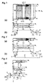
- the sensor of Fig. 4 comprises a planar optical waveguide WG sandwiched between a substrate S and a sensing layer SL, with a cover medium C.
- a cover medium C For reasons of simplicity, only one waveguide layer and only one sensing layer is shown; however, the waveguide and/or the sensing layer could be built up of a plurality of layers.
- the sensor makes use of a pair of chirped grating couplers 1.1, 1.2, an input grating coupler 1.1 and an output grating coupler 1.2.
- a pair of chirped grating couplers 1.1, 1.2 an input grating coupler 1.1 and an output grating coupler 1.2.
- gratings are shown on both surfaces of the waveguide WG; it is, however, clear to a person skilled in the art that a resonant waveguide grating structure can be realized in other ways, e.g., by a grating on only one surface of the waveguide WG.
- a resonance condition analogous to Eq. (1) also holds for the output coupler.
- Light is typically emitted from a light source 3, incoupled in the form of an incident plane wave u i , 21, guided as a mode 22 in the waveguide WG and is outcoupled in the form of an excident plane wave u o , 23, under an angle ⁇ o .
- all waveguide parameters such as the waveguide thickness or the refractive indices are spatially uniform, whereas the grating periods ⁇ (y) linearly depend on the lateral coordinate y; in other embodiments, the waveguide thickness and/or the refractive indices could depend on y.
- the effective index N depends, among other parameters, also on the refractive index of the material SL on the waveguide surface and consequently on a measurand M on the waveguide surface. From the resonance condition Eq. (1) it follows that a mode position y b1 changes to a position y b2 upon a change of the measurand's value from M 1 to M 2 .
- the guided mode 22 in the sensor of Fig. 4 is thus called an IO light pointer (IOLP).
- the mode position y b1 is detected by a detector 4 arranged to detect the outcoupled light 23, yielding an output signal 41.
- the detector can be realized as, e.g., a charge-coupled device (CCD) array.
- the sensor of Fig. 4 has several disadvantages. Firstly, its dynamic range is proportional to its width (in y direction). Therefore, in order to obtain a high dynamic range, the sensor width and sensor area have to be very large, which is undesirable for the reasons discussed above. As a second disadvantage, the quality of the sensor signal 41 is reduced by imperfections in the waveguide WG, the sensing layer SL, the substrate S etc., e.g., by light scattering. Moreover, the chirp of the grating 1 and the waveguide parameters cannot be made perfectly homogeneous over the entire width of the sensor, which reduces the sensor sensitivity.
- Figure 5 shows a first embodiment of an IO sensor used in the invention in a top view ( Fig. 5(a) ) and a side view (Fig. 5(b)) .
- the sensor is provided with two chirped gratings 1.1, 1.2 as in the arrangement of Fig. 4.
- the width (in y direction) of the sensor is strongly reduced compared with that of Fig. 4.
- the size of the entire sensing unit (i.e., the pair of grating pads1.1, 1.2) in the y-direction is preferably smaller than 5 times the width of the guided mode 22 or smaller than 1 mm. With such a small lateral dimension, the dynamic range of a conventional sensor according to Fig. 4 would be unacceptably low.
- the senor used in the invention actively clamps or stabilizes the lateral position y b of the guided mode 22 to be constant by means of an additional degree of freedom.
- the additional degree of freedom may be, e.g., the wavelength of light ⁇ ; other possible degrees of freedom are the angle of incidence ⁇ i or the spectral light distribution.
- a feedback is provided from the detector 4 to the light source 3, thus establishing a controlled closed-loop system.
- the drawbacks discussed with reference to Fig. 4 are eliminated by changing the wavelength ⁇ of the light source 3 in order to keep the IOLP position y b fixed at all times.
- a substantial reduction in sensor size is achieved by compensating the effect of the measurand M.
- the dynamic range of this sensor is no longer determined by the physical size of the sensing unit, but by the range ⁇ in which the wavelength ⁇ can be varied, and of the chirp of the grating coupler 1.1. Inhomogeneities of the sensor are of minor importance because the sensor width and area are extremely small.
- Typical thicknesses of waveguiding films WG are in the range between 100 nm and 300 nm, e.g., 150 nm.
- the light source 3 is typically narrow-band light source such as a laser emitting a wavelength of, e.g., 632.8 nm, 650 nm, 785.1 nm or 980 nm.
- Typical grating periods A are in the range between 250 nm and 500 nm.
- Singly periodic, multiply periodic and/or superposed gratings 1.1, 1.2 may be used.
- a plurality of wavelengths, incoupling angles and/or polarizations may be present at the same time.
- the wavelengths, incoupling angles and/or polarizations may be discrete or exhibit a broad-band distribution.
- a further reduction of the sensor dimensions can be achieved with the sensor shown in Figure 6 (top view, Fig. 6(a), side view, Fig. 6(b) ), which is a further development of the embodiment of Fig. 5.
- the sensor dimensions are reduced also in the z direction by means of introducing yet another degree of freedom, for example by using a single grating coupler 1 working at two (or more) different diffraction orders.
- Yet another degree of freedom could by introduced by observing scattered light emitted from the grating structure (cf. Fig. 7)
- > 2 can also be used for in- or outcoupling.
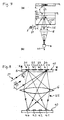
- Figure 7 shows a further embodiment of an IO sensor used in the invention.
- the intensity distribution of light 25 scattered in the region of the resonant waveguide grating structure 1 is measured.
- a measurement can be performed by imaging at least a part of the resonant waveguide grating structure 1 onto a light intensity detector 4, e.g., a photodiode, by means of an imaging system 6.
- the sensor could alternatively dispense with the imaging system 6 if the light detector 4 was placed near the resonant waveguide grating structure 1 (cf. Fig. 11(a)).
- the scattered light 25 could also be guided to a detector by an optical fiber.
- Light scattering may have "natural” causes such as imperfections in the resonant waveguide grating structure 1, or “artificial” causes such as roughening of the waveguide surface or implanted imperfections in the waveguide WG.
- the intensity of the scattered light 25 is a measure for the photon density in the region of the resonant waveguide grating structure 1, which is high if a resonant electromagnetic field 22 is excited by the incident light 21 and low otherwise.
- the embodiment of Fig. 7 is an example of resonant incoupling and non-resonant outcoupling.
- a feedback loop (here not shown) for controlling a parameter of the incident light, e.g., its wavelength, could be provided as in Figs. 5 and 6.
- Figure 8 shows a side view of an embodiment of a multiple arrangement of IO sensors used in the invention.
- a plurality of IO sensors S1-S4 are arranged in e.g., an array in a surface plane 10 on a transparent substrate S.
- the details of the resonant waveguide grating structures 1.1-1.4 can be similar as those in Figs. 5-7 and are not shown in Fig. 8.
- filter structures as described in D. Shin, S. Tibuleac, Th. A Maldonado and R. Magnusson, "Thin-film optical filters with diffractive elements and waveguides", Opt, Eng. 37(9), 2634-2646 (September 1998) can be used.
- the IO sensors S1-S4 of this multiple arrangement are operated by resonant incoupling and non-resonant outcoupling, as the sensor shown in Fig. 7.
- the angle of incidence is preferably chosen to be the Brewster angle ⁇ B ; then, if the incoming light is p polarized, undesirable reflected light is reduced almost to zero.
- n WG 2.350
- n SL 1.405
- n C 1.328
- the surface plane 10 containing the resonant waveguide grating structures 1.1-1.4 is imaged onto a surface plane 40 containing a plurality of light intensity detectors 4.1-4.4 by an imaging system 6.
- the intensity of light 25 scattered in the region of the resonant waveguide grating structures 1.1-1.4 is measured by the light detectors4.1-4.4.
- each detector 4.1-4.4 is biuniquely assigned to a certain resonant waveguide grating structure 1.1-1.4.
- a parameter of the incident light 21, preferably the wavelength ⁇ 1 is varied with time in order to excite resonant electromagnetic fields in the resonant waveguide grating structures 1.1-1.4.
- the arrangement of Fig. 8 can also be operated by imaging resonantly outcoupled light in a chosen diffraction order onto the detector.
- Figure 9 shows a preferred embodiment of a multiple arrangement of IO sensors S1, S2, ... used in the invention in a top view ( Fig. 9(a) ) and a side view ( Fig. 9(b) ).
- the sensors S1, S2, ... are arranged in a two-dimensional array on a substrate S, e.g., in equally spaced rows and columns.
- the sensors S1, S2, ... can be used for obtaining a measuring signal or a referencing signal (cf. Fig. 1), i.e., some of them could also be referenced as R.
- They are illuminated preferably by a single incident light beam 21 with a defined wavelength ⁇ 1 under a defined angle of incidence ⁇ 1 .
- the incident light 21 could provide a wide range of wavelengths, different polarizations and/or a wide range of angles of incidence, or could contain a plurality of discrete wavelengths and/or of discrete angles of incidence.
- a parameter or several parameters of the incident light 21 such as the wavelength ⁇ 1 , the angle of incidence ⁇ 1 , the polarization and/or the wavefront is varied during the measurement. If the resonance conditions are fulfilled, the incident light 21 excites a resonant electromagnetic field in at least one resonant waveguide grating structure 1.1, 1.2, ... As a measure for resonance, e.g., the light distribution of resonantly outcoupled light 23 is detected for each resonant waveguide grating structure 1.1, 1.2, ... by light position detectors 4.1, 4.2, ..., e.g., CCD arrays.
- an imaging system 6 can be arranged between the resonant waveguide grating structures 1.1, 1.2, ... and the position detectors 4.1, 4.2, ...
- each position detector 4.1, 4.2, ... is biuniquely assigned to a certain resonant waveguide grating structure 1.1, 1.2, ...
- a cylindrical focusing optical system (not shown) can be used, the position detectors 4.1, 4.2, ... lying in the focal plane 40 of the cylindrical optical system.
- the cylindrical optical system acts as means for the variation of the angle of excidence into a variation of light position on the detectors 4.1, 4.2, ...; in other words, it performs an optical Fourier transform of the outcoupled light 23.
- FIG 10 various means for varying the angle of incidence ⁇ 1 are shown.
- Light 21 is emitted by a point light source 3, e.g., a vertical cavity surface emitting laser (VCSEL), a distributed feedback (DFB) laser or a distributed Bragg reflector (DBR) laser, which lies in a focal plane 30 of a collimating optical system 31.
- a point light source 3 e.g., a vertical cavity surface emitting laser (VCSEL), a distributed feedback (DFB) laser or a distributed Bragg reflector (DBR) laser, which lies in a focal plane 30 of a collimating optical system 31.
- the position of the optical system 31 is varied from a first position (full lines) to a second position (dashed lines), thus varying the angle of incidence from ⁇ 1 to ⁇ 2 .
- the position of the point light source 3 is varied.
- the embodiment of Figure 10(c) does not require any moving parts.
- a plurality of point light sources 3.1-3.5 arranged in the focal plane 30 of a collimating optical system 31 is provided.
- the angle of incidence ⁇ 1 is discretely varied by switching on different light sources 3.1-3.5.
- a further possibility for variation is the use of a mirror 32 rotatable around a rotation axis a as shown in Figure 10(d) .
- the variation of the angle of incidence can be used for exciting a resonant electromagnetic field in a resonant waveguide grating structure, but also in order to compensate for chip tolerances and/or to achieve a wider dynamic range.
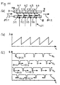
- FIG. 11(a) A further embodiment of a multiple arrangement of IO sensors S1, S2, ... used in the invention is shown in Figure 11(a) in a side view.
- the resonant waveguide grating structures 1.1, 1.2, ... can, e.g., be arranged in a two-dimensional array on a first substrate S as in Fig. 9.
- Various resonant waveguide grating structures 1.1, 1.2, ... as discussed with reference to the previous figures can be used.
- Other angles of incidence as shown in the previous figures, e.g., the Brewster angle (cf. Fig. 8), are also possible.
- an array of light intensity detectors 4.1, 4.2, ..., e.g., a photodiode array, on a second substrate D is positioned close to the resonant waveguide grating structures 1.1, 1.2, ...
- the light detectors 4.1, 4.2, ... measure, e.g., the intensity of transmitted light (not shown) for the corresponding resonant waveguide grating structures 1.1, 1.2, ...
- the embodiment of Fig. 11(a) presents the following differences: the transmitted light is measured instead of reflected light, and it is detected directly without an imaging system.
- the gap 8 between the first substrate S and the second substrate D can be used as a channel for an analyte, the flow of which is symbolized by arrows 81.1, 81.2.
- the resonant electromagnetic fields in the resonant waveguide grating structures are excited by varying a parameter of the incident light, e.g., its wavelength ⁇ .
- Figure 11(b) shows a periodic variation of the wavelength ⁇
- Figure 11(c) shows possible corresponding sensor output signals s 1 , s 2 , ... versus time t.
- Minimums or dips 91.1, 91.2, ... of the output signals s 1 , s 2 , ... are periodically detected at different times, i.e., at different wavelengths, if the sensors S1, S2, ... and/or their environments are not exactly identical.
- This arrangement is particularly fitted for measuring changes in refractive index absorption or scattering properties, or any combination thereof.
- the achievable precision (sensitivity, resolution) of the sensing process depends critically on the proper evaluation (e.g. determination of the positions of the dips in the arrangements according to Fig. 11, or of corresponding intensity peaks which will typically be observed in the arrangements of Figs. 7, 8, 9 working in the domain of reflection).
- FIG. 12 shows various embodiments of resonant waveguide grating structures 1.3-1.6 for an IO sensor according to the invention ( Figures 12(a), (c), (e) and (g) ), and their electromagnetic field intensities I versus the y coordinate ( Figures 12(b), (d), (f) and (h) ).
- the intensity I(y) of an electromagnetic field resonantly excited via a chirped grating 1.3 exhibits a sharp peak 93 at a certain position y b1 ( Figure 12(b) ; cf. Figure 5(a)).
- the intensity signal of Fig. 12(b) can be fitted (using, e.g., a Gaussian intensity distribution model).
- the peak 93 moves from its original position y b1 (full line) towards a different position y b2 (dashed line) if a parameter of the waveguide or of the incident light such as the wavelength is changed.
- the peak 93 can be clamped or stabilized at a certain y position by providing a controlled closed-loop system.
- the discrete grating 1.4 of Figure 12(c) is obtained by dividing the chirped grating 1.3 of Fig. 12(a) into a plurality of regions 1.41-1.44, i.e., stripes in y direction, and providing in each region 1.41-1.44 a homogeneous grating with a grating period which is equal to an average grating period of the corresponding region in the chirped grating 1.3.
- the intensity distribution I(y) generally exhibits different levels for the different regions 1.41-1.44; the levels change with varying light parameters or waveguide parameters ( Figure 12(d) ).
- the value of a measurand M can be evaluated by interpolating between two intensity distributions for known measurands M 1 , M 2 .
- the intensity levels can also be clamped or stabilized to be constant by providing a controlled closed-loop system 5.
- the discrete gratings need not be adjacent to each other, and their grating periods need not increase monotonously with the y coordinate, as is the case for the resonant waveguide grating structure 1.5 of Figure 12(e) ; a possible corresponding intensity distribution I(y) is shown in Figure 12(f) .
- the embodiment of Figure 12(g) has a non-periodic resonant waveguide grating structure 1.6. It exhibits a generally irregular intensity distribution I(y) such as sketched in Figure 12(h) .
- Fig. 12(g) has the advantages that imperfections of the resonant waveguide grating structure 1.6 do not disturb the measurements, and that a mathematical fit of a measured intensity distribution I(y) need not be performed.
- a method for the signal evaluation shall be presented.
- the output signals s 1 and s 2 are known for known measurand values M 1 and M 2 , respectively.
- the embodiment of Figure 13 shown in a top view applies the principle of Figs. 12(g) and (h) to a multiple arrangement of IO sensors.
- the resonant waveguide grating structures 1.1, 1.2, ... need not be in rows or columns.
- the resonant waveguide grating structure 1.3 is an example of two superposed gratings.
Landscapes
- Physics & Mathematics (AREA)
- Chemical & Material Sciences (AREA)
- Engineering & Computer Science (AREA)
- Chemical Kinetics & Catalysis (AREA)
- Plasma & Fusion (AREA)
- Health & Medical Sciences (AREA)
- Life Sciences & Earth Sciences (AREA)
- Analytical Chemistry (AREA)
- Biochemistry (AREA)
- General Health & Medical Sciences (AREA)
- General Physics & Mathematics (AREA)
- Immunology (AREA)
- Pathology (AREA)
- Investigating Or Analysing Materials By Optical Means (AREA)
Description
- The invention relates to a chemical and/or biochemical optical sensor, a multiple arrangement of a plurality of such sensors and a method for optically sensing a substance, according to the preambles of the independent claims.
- Many present and upcoming applications of chemical and/or biochemical microsystems, especially for application areas such as medical, food and environmental, require the detection of several analytes being simultaneously present in a liquid. One well-known and advantageous type of detection is optical. An important class of such optical sensors are integrated optical (IO) sensors comprising a chip with a waveguide and sensing biolayers. An example for this type of device is disclosed in WO 92/19976. Other patents have also been applied for in recent years and work has been published by various groups worldwide.
- Different sensing principles are being used in IO chemical and/or biochemical sensors. These principles and arrangements allow one to integrate many sensing pads or sensors on one single chip for realizing on-chip referencing and complex analyte sensing.
- In this document, the term "sensor" stands for "sensing" elements used for chemical and/or biochemical measurements as well as for "referencing" elements used for reference measurements. This is to avoid ambiguities, since there are many aspects which apply to both, sensing and referencing sensors, and referencing sensors can be considered to just represent a special type of measuring sensors, used to perform on-chip referencing.
- WO 97/29362 discloses a sensor with a planar waveguide formed on the surface of a substrate. A surface grating is formed in one of the surfaces of the waveguide. A beam of light is incident on the grating, and the angle of incidence at which maximum reflection occurs is monitored. Changes in the angle provide an indication of a chemical reaction on the surface of the waveguide. The apparatus has the disadvantage that the output signal is disturbed by parasitic reflections occurring at all interfaces between the different media (air, substrate, waveguide, sensing layer, cover medium). Consequently, the signal-to-noise ratio is low.
- An integrated spectrometer for chemical analysis is disclosed in US-5,082,629. The spectrometer also comprises a planar waveguide on the surface of a substrate. The waveguide has an entrance grating and an exit grating. Light from a light source is coupled into the waveguide by the entrance grating. An analyte on the surface of the waveguide interacts with the guided light via the effect of attenuated total internal reflection. Thus, light coupled out of the waveguide by the exit grating carries information on the absorption characteristics of the analyte, which information is detected by a photodetector. The spectrometer cannot be miniaturized since it requires two gratings with a long interaction section in between.
- It is known from the state of the art to arrange IO sensors in an array pattern. However, only one-dimensional IO sensor arrays permit independent simultaneous ("parallel") measurements. More complex, e.g., two-dimensional, sensor arrays seriously suffer from crosstalk between the various IO channels, i.e., the optical signals cannot be separated in an acceptable way.
- A further disadvantage of known multiple IO sensor arrangements is that the sensors require too much of chip area, leading to very big chips and also to a small ratio between active and passive area. (In this document, the term "active area" denotes the area of the IO sensor in which an interaction of the measurand with the light takes place.) They also need too much of (bio-)chemical area, since this is not efficiently used. Another problem with presently known array detection schemes is that the efficiency of on-chip referencing is limited by the large distance between sensing and referencing sensors due to their large size.
- US5738825 discloses an optical chemical sensor comprising a waveguide grating structure in which light from a laser is incident on the grating as a beam which has been focused into a fan shape or expanded over several cells and in which the light coupled out of the same or a different grating is incident on detectors. The incident light is retro reflected into the same fan beam cone in which the light was incident so as not to be incident as background noise on detectors which are arranged so as to detect light coupled out at angle larger than the angle of incidence.
- It is an object of the invention to provide a multiple arrangement of IO sensors which makes possible independent simultaneous ("parallel") measurements with the sensors. It is a further object to provide an IO sensor for use in such a multiple arrangement. It is still a further object to indicate a method for integrated-optically sensing a chemical and/or biochemical substance using such a sensor.
- The invention also aims at removing other drawbacks of the state-of-the art solutions for achieving high-density array IO sensors. In particular, it is another object of the invention to provide a multiple arrangement of IO sensors with:
- more efficient on-chip referencing,
- chip and system miniaturization, i.e., more sensors per chip area (in the case of a two-dimensional sensor) or per volume (in the case of a three-dimensional sensor),
- less chemicals needed for chip biocoating, and
- less analyte volume needed due to reduced chip area for performing same task.
- To take full advantage for practical applications, the following constraints shall be taken into account:
- the sensitivity is maintained or increased with respect to the conventional solutions, and
- the dynamic range is maintained or increased with respect to the conventional solutions.
- The objects are resolved by the IO sensor, the multiple arrangement of IO sensors and the method as defined in the independent claims.
- The multiple one-, two- or three-dimensional arrangement according to the invention comprises a plurality of sensors as defined above.
- According to the invention, the functionality of the measuring pads is increased. The measuring pad geometry is adapted to the sensing principle, to the overall chip geometry, and to the particular application. The efficiency of light collection (in general: ,optical transfer processes") is enhanced. Use is made of additional on-chip and/or off-chip and/or general degrees of freedom. The area required for performing the sensing task is reduced, especially by reducing the area required by a single measuring pad in an array, and by increasing the ratio between active and passive chip area.
- Hence, a much higher density of sensors results for single-chip IO sensor arrangements, leading to several advantages as is described below. As an example, we will consider advantages for on-chip referencing, which is eased due to the smaller distance, and because multiple referencing sensors can be used per sensing pad, e.g. one on top and one below or left and right or distributed around etc. This is especially important for sensors with very high sensitivities, since they are more affected by unspecific effects such as temperature and signal drift due to chemical and physical fluctuations and chip deformation.
- The invention is described in greater detail hereinafter, compared with the prior art, relative to the attached schematic drawings.
- Fig. 1
- shows an IO sensor with a two-dimensional array of measuring pads.
- Fig. 2
- shows the influence of disturbances and its dependence on the distance and/or size of the sensing pads.
- Fig. 3
- shows applications of IO sensors for high-density zero-, one-, two- and three-dimensional sensing.
- Fig. 4
- shows an IO sensor according to the state of the art with a pair of chirped gratings.
- Figs. 5 and 6
- show a first and a second embodiment, respectively, of an IO sensor used in the invention.
- Fig. 7
- shows a further embodiment of an IO sensor used in the invention.
- Figs. 8 and 9
- show two embodiments of a multiple arrangement of IO sensors used in the invention.
- Fig. 10
- shows means for varying the angle of incidence.
- Fig. 11
- shows a further embodiment of a multiple arrangement of IO sensors used in the invention, and the variation in time of the input wavelength and the output signals.
- Fig. 12
- shows various embodiments of resonant waveguide grating structures for an IO sensor used in the invention, and their spatial output signals
- Fig. 13
- shows a further embodiment of a multiple arrangement of IO sensors used in the invention.
- The Figures 1-3 serve to illustrate the motivation for the invention. Figure 1 shows an example of a two-dimensional sensor array featuring sensing pads S and referencing pads R. These are distributed in a manner to have the most sensitive sensing pads S surrounded by referencing pads R on all sides. This ensures that on-chip referencing is also effective to eliminate gradients of disturbances. The measuring pads S, R are drawn as rectangles; however, they may have any other geometric form such as circles, triangles etc.
- The influence of disturbances, e.g, temperature gradients, and its dependence on the distance and/or size of the sensing pads is illustrated in Figures 2(a) and (b). Figure 2(a) shows a linear (i.e., one-dimensional) array of measuring pads S0, R1, S1, R2, S2, ..., where a
sensing pad S 1 is surrounded by two referencing pads R1, R2. Figure 2(b) shows two different temperature distributions T(z) versus a position z. The positions of the pads R1, S1, R2, in Fig. 2(a) are z1, z2 and z3, respectively. For compensation of an undesirable temperature effect, the reference signals of the pads R1 and R2 are linearly interpolated. In case of a linear gradient, the compensation is perfect; in case of a nonlinear gradient, the quality of compensation depends on the degree of nonlinearity and on the distance of the pads. While there is only minor influence on the global nonlinearity of the disturbance, the present invention achieves a marked improvement by reducing the pad size, which reduces the degree of the nonlinearity on a local scale, i.e., in the region between the referencing pads. - A size reduction of the measuring pads is also important for applications such as the tip sensor shown in Figure 3(a). Such a tip sensor with, e.g., one sensing S pad on a pen tip, is in fact a zero-dimensional IO sensor. It is important to reduce the tip size in order to get a high spatial resolution and/or to be able to use the sensor in locations where there is not much space, e.g., in the body of human beings or animals. If a high degree of size reduction is achieved, small arrays of one-dimensional or two-dimensional arrangements can also be used on such tip-sensors (e.g., one sensing pad surrounded by four referencing pads).
- Very important applications are high-density one-dimensional and two-dimensional sensing, as is shown in Figures 3(b) and 3(c), (d), respectively. The advantages of increasing the pad density per unit of length (Fig. 3(b)) and per unit of area (Figs. 3(c) and (d)) have already been stated above.
- Making further use of measuring pad size reduction, one can further increase the pad density also per volume in three-dimensional arrangements, an example of which is given in Figure 3(e). This is especially interesting for gas sensing.
- Figure 4 shows a sensor known from the state of the art which has been used in recent years for performing chemical and biochemical measurements and is disclosed in the following publications:
- WO 92/19976;
- R.E. Kunz, "Totally Integrated Optical Measuring Sensors," Proc. SPIE, Vol. 1587, 98-113 (1992);
- R.E. Kunz, "Miniature Integrated Optical Modules for Chemical and Biochemical Sensing", Sensors and Actuators B, Vol. 38-39, 13-28 (1997).
- The sensor of Fig. 4 comprises a planar optical waveguide WG sandwiched between a substrate S and a sensing layer SL, with a cover medium C. For reasons of simplicity, only one waveguide layer and only one sensing layer is shown; however, the waveguide and/or the sensing layer could be built up of a plurality of layers. The sensor makes use of a pair of chirped grating couplers 1.1, 1.2, an input grating coupler 1.1 and an output grating coupler 1.2. In the side view of Fig. 4(b), gratings are shown on both surfaces of the waveguide WG; it is, however, clear to a person skilled in the art that a resonant waveguide grating structure can be realized in other ways, e.g., by a grating on only one surface of the waveguide WG. The well-known input coupler resonance condition for achieving maximum coupling efficiency is given by

light source 3, incoupled in the form of an incident plane wave ui, 21, guided as amode 22 in the waveguide WG and is outcoupled in the form of an excident plane wave uo, 23, under an angle θo. In the sensor of Fig. 4, all waveguide parameters such as the waveguide thickness or the refractive indices are spatially uniform, whereas the grating periods Λ(y) linearly depend on the lateral coordinate y; in other embodiments, the waveguide thickness and/or the refractive indices could depend on y. The effective index N depends, among other parameters, also on the refractive index of the material SL on the waveguide surface and consequently on a measurand M on the waveguide surface. From the resonance condition Eq. (1) it follows that a mode position y b1 changes to a position y b2 upon a change of the measurand's value from M1 to M2. The guidedmode 22 in the sensor of Fig. 4 is thus called an IO light pointer (IOLP). The mode position y b1 is detected by adetector 4 arranged to detect the outcoupled light 23, yielding anoutput signal 41. The detector can be realized as, e.g., a charge-coupled device (CCD) array. - The sensor of Fig. 4 has several disadvantages. Apparently, its dynamic range is proportional to its width (in y direction). Therefore, in order to obtain a high dynamic range, the sensor width and sensor area have to be very large, which is undesirable for the reasons discussed above. As a second disadvantage, the quality of the
sensor signal 41 is reduced by imperfections in the waveguide WG, the sensing layer SL, the substrate S etc., e.g., by light scattering. Moreover, the chirp of thegrating 1 and the waveguide parameters cannot be made perfectly homogeneous over the entire width of the sensor, which reduces the sensor sensitivity. - Figure 5 shows a first embodiment of an IO sensor used in the invention in a top view (Fig. 5(a)) and a side view (Fig. 5(b)). The sensor is provided with two chirped gratings 1.1, 1.2 as in the arrangement of Fig. 4. However, the width (in y direction) of the sensor is strongly reduced compared with that of Fig. 4. The size of the entire sensing unit (i.e., the pair of grating pads1.1, 1.2) in the y-direction is preferably smaller than 5 times the width of the guided
mode 22 or smaller than 1 mm. With such a small lateral dimension, the dynamic range of a conventional sensor according to Fig. 4 would be unacceptably low. In order to overcome this impediment, the sensor used in the invention actively clamps or stabilizes the lateral position y b of the guidedmode 22 to be constant by means of an additional degree of freedom. The additional degree of freedom may be, e.g., the wavelength of light λ; other possible degrees of freedom are the angle of incidence θi or the spectral light distribution. The effect of changing the wavelength on the IOLP position y b has been investigated and demonstrated in the following publications: - R.E. Kunz and J. Dubendorfer, "Miniature Integrated Optical Wavelength Analyzer Chip," Optics Letters, Vol. 20, 2300-2303 (1995);
- M. Wiki, J. Dübendorfer and R.E. Kunz, "Spectral Beam Sampling and Control by a Planar Optical Transducer," Sensors and Actuators A, Vol. 67/1-3, 120-124 (15 May 1998).
- A feedback is provided from the
detector 4 to thelight source 3, thus establishing a controlled closed-loop system. Hence, the drawbacks discussed with reference to Fig. 4 are eliminated by changing the wavelength λ of thelight source 3 in order to keep the IOLP position y b fixed at all times. A substantial reduction in sensor size is achieved by compensating the effect of the measurand M. The dynamic range of this sensor is no longer determined by the physical size of the sensing unit, but by the range Δλ in which the wavelength λ can be varied, and of the chirp of the grating coupler 1.1. Inhomogeneities of the sensor are of minor importance because the sensor width and area are extremely small. - Other components of the sensor are described in detail with reference to Fig. 4 and need no further explanation. Typical materials and parameters of the sensor are the following. The substrate S is made of, e.g., polycarbonate (ns = 1.57), glass, e.g., AF45 (ns = 1.52) or quartz (ns = 1.45), or silicon. It also may consist of several materials, e.g., of an SiO2 layer on silicon. The waveguiding film WG is made of, e.g., TiO2 (nWG = 2.35), Si3N4 (nWG = 1.8-2.1) or Ta2O5 (nWG = 2.20); a combination of several layers is also possible. Typical thicknesses of waveguiding films WG are in the range between 100 nm and 300 nm, e.g., 150 nm. The sensing layer SL consists of one or several substances to be sensed. Optionally, it may include one or several layers of proteins (nSL = 1.35-1.55) which are capable of binding (bio-)chemical substances to be sensed. Such substances are typically transported to the sensor in an aqueous solution (nC = 1.33). The
light source 3 is typically narrow-band light source such as a laser emitting a wavelength of, e.g., 632.8 nm, 650 nm, 785.1 nm or 980 nm. Typical grating periods A are in the range between 250 nm and 500 nm. Singly periodic, multiply periodic and/or superposed gratings 1.1, 1.2 may be used. A plurality of wavelengths, incoupling angles and/or polarizations may be present at the same time. The wavelengths, incoupling angles and/or polarizations may be discrete or exhibit a broad-band distribution. - A further reduction of the sensor dimensions can be achieved with the sensor shown in Figure 6 (top view, Fig. 6(a), side view, Fig. 6(b)), which is a further development of the embodiment of Fig. 5. In this embodiment, the sensor dimensions are reduced also in the z direction by means of introducing yet another degree of freedom, for example by using a single
grating coupler 1 working at two (or more) different diffraction orders. Yet another degree of freedom could by introduced by observing scattered light emitted from the grating structure (cf. Fig. 7) In the example of Fig. 6, the diffraction order mg = 1 is used for incoupling and the diffraction order mg = -2 is used for outcoupling. Hence the diffraction orders mg = 0 (reflected) and mg = 1, forming the wave ur,, 24, do not disturb the sensor signal by lessening the signal-to-noise ratio. Of course, higher diffraction orders |mg| > 2 can also be used for in- or outcoupling. - Figure 7 shows a further embodiment of an IO sensor used in the invention. Instead of measuring and controlling the y position of the resonantly outcoupled light, the intensity distribution of
light 25 scattered in the region of the resonant waveguidegrating structure 1 is measured. Such a measurement can be performed by imaging at least a part of the resonant waveguidegrating structure 1 onto alight intensity detector 4, e.g., a photodiode, by means of an imaging system 6. The sensor could alternatively dispense with the imaging system 6 if thelight detector 4 was placed near the resonant waveguide grating structure 1 (cf. Fig. 11(a)). In another embodiment (not shown), thescattered light 25 could also be guided to a detector by an optical fiber. Light scattering may have "natural" causes such as imperfections in the resonant waveguidegrating structure 1, or "artificial" causes such as roughening of the waveguide surface or implanted imperfections in the waveguide WG. - The intensity of the scattered
light 25 is a measure for the photon density in the region of the resonant waveguidegrating structure 1, which is high if a resonantelectromagnetic field 22 is excited by theincident light 21 and low otherwise. By measuring the intensity of the scatteredlight 25, undesirable contributions of the diffraction orders mg = 0 (reflected) and mg = 1, 24, to the measuredsignal 41 are avoided, thus yielding a better signal-to noise ratio. The embodiment of Fig. 7 is an example of resonant incoupling and non-resonant outcoupling. A feedback loop (here not shown) for controlling a parameter of the incident light, e.g., its wavelength, could be provided as in Figs. 5 and 6. - Figure 8 shows a side view of an embodiment of a multiple arrangement of IO sensors used in the invention. A plurality of IO sensors S1-S4 are arranged in e.g., an array in a
surface plane 10 on a transparent substrate S. The details of the resonant waveguide grating structures 1.1-1.4 can be similar as those in Figs. 5-7 and are not shown in Fig. 8. Alternatively, filter structures as described in D. Shin, S. Tibuleac, Th. A Maldonado and R. Magnusson, "Thin-film optical filters with diffractive elements and waveguides", Opt, Eng. 37(9), 2634-2646 (September 1998) can be used. The IO sensors S1-S4 of this multiple arrangement are operated by resonant incoupling and non-resonant outcoupling, as the sensor shown in Fig. 7. Preferably onesingle light beam 21 illuminates all the sensors S1-S4; alternatively, a plurality of light beams can be used. The angle of incidence is preferably chosen to be the Brewster angle θB; then, if the incoming light is p polarized, undesirable reflected light is reduced almost to zero. For a typical sensor with a substrate S made of polycarbonate (ns = 1.571), a TiO2 waveguiding film WG (nWG = 2.350) having a thickness of 150 nm, a protein layer (nSL = 1.45) as a sensing layer SL and a cover C of water (nC = 1.328), and the wavelength of the incident light being λ = 785 nm, the Brewster angle is θB = 57.5°. For a resonant incoupling in the diffraction order mg = 1, a grating period of A = 306 nm must be provided, according to Eq. (1). - The
surface plane 10 containing the resonant waveguide grating structures 1.1-1.4 is imaged onto asurface plane 40 containing a plurality of light intensity detectors 4.1-4.4 by an imaging system 6. In analogy to Fig. 7, the intensity of light 25 scattered in the region of the resonant waveguide grating structures 1.1-1.4 is measured by the light detectors4.1-4.4. Preferably each detector 4.1-4.4 is biuniquely assigned to a certain resonant waveguide grating structure 1.1-1.4. In a measurement, a parameter of theincident light 21, preferably the wavelength λ1, is varied with time in order to excite resonant electromagnetic fields in the resonant waveguide grating structures 1.1-1.4. - Analogously, the arrangement of Fig. 8 can also be operated by imaging resonantly outcoupled light in a chosen diffraction order onto the detector.
- Figure 9 shows a preferred embodiment of a multiple arrangement of IO sensors S1, S2, ... used in the invention in a top view (Fig. 9(a)) and a side view (Fig. 9(b)). The sensors S1, S2, ... are arranged in a two-dimensional array on a substrate S, e.g., in equally spaced rows and columns. The sensors S1, S2, ... can be used for obtaining a measuring signal or a referencing signal (cf. Fig. 1), i.e., some of them could also be referenced as R. They are illuminated preferably by a single
incident light beam 21 with a defined wavelength λ1 under a defined angle of incidence θ1. Alternatively, theincident light 21 could provide a wide range of wavelengths, different polarizations and/or a wide range of angles of incidence, or could contain a plurality of discrete wavelengths and/or of discrete angles of incidence. - A parameter or several parameters of the incident light 21 such as the wavelength λ1, the angle of incidence θ1, the polarization and/or the wavefront is varied during the measurement. If the resonance conditions are fulfilled, the
incident light 21 excites a resonant electromagnetic field in at least one resonant waveguide grating structure 1.1, 1.2, ... As a measure for resonance, e.g., the light distribution of resonantly outcoupled light 23 is detected for each resonant waveguide grating structure 1.1, 1.2, ... by light position detectors 4.1, 4.2, ..., e.g., CCD arrays. For this purpose, an imaging system 6 can be arranged between the resonant waveguide grating structures 1.1, 1.2, ... and the position detectors 4.1, 4.2, ... Preferably each position detector 4.1, 4.2, ... is biuniquely assigned to a certain resonant waveguide grating structure 1.1, 1.2, ... - Instead of the imaging system 6, a cylindrical focusing optical system (not shown) can be used, the position detectors 4.1, 4.2, ... lying in the
focal plane 40 of the cylindrical optical system. The cylindrical optical system acts as means for the variation of the angle of excidence into a variation of light position on the detectors 4.1, 4.2, ...; in other words, it performs an optical Fourier transform of theoutcoupled light 23. - In Figure 10, various means for varying the angle of incidence θ1 are shown.
Light 21 is emitted by a pointlight source 3, e.g., a vertical cavity surface emitting laser (VCSEL), a distributed feedback (DFB) laser or a distributed Bragg reflector (DBR) laser, which lies in afocal plane 30 of a collimatingoptical system 31. In the embodiment of Figure 10(a), the position of theoptical system 31 is varied from a first position (full lines) to a second position (dashed lines), thus varying the angle of incidence from θ1 to θ2. In the embodiment of Figure 10(b), the position of the pointlight source 3 is varied. The embodiment of Figure 10(c) does not require any moving parts. Instead, a plurality of point light sources 3.1-3.5 arranged in thefocal plane 30 of a collimatingoptical system 31 is provided. The angle of incidence θ1 is discretely varied by switching on different light sources 3.1-3.5. A further possibility for variation is the use of amirror 32 rotatable around a rotation axis a as shown in Figure 10(d). The variation of the angle of incidence can be used for exciting a resonant electromagnetic field in a resonant waveguide grating structure, but also in order to compensate for chip tolerances and/or to achieve a wider dynamic range. - A further embodiment of a multiple arrangement of IO sensors S1, S2, ... used in the invention is shown in Figure 11(a) in a side view. The resonant waveguide grating structures 1.1, 1.2, ... can, e.g., be arranged in a two-dimensional array on a first substrate S as in Fig. 9. Various resonant waveguide grating structures 1.1, 1.2, ... as discussed with reference to the previous figures can be used. In this embodiment, the angles of incidence are chosen to be near zero, i.e., θi = 0; this simplifies the illumination/readout configuration. Other angles of incidence as shown in the previous figures, e.g., the Brewster angle (cf. Fig. 8), are also possible. A typical waveguide has a substrate S made of polycarbonate (ns = 1.571), a TiO2 waveguiding film WG (nWG = 2.350) having a thickness of 150 nm, a protein layer (nSL = 1.45) as a sensing layer SL and a cover C of water (nC = 1.328), and the wavelength of the incident light is 785 nm. From Eq. (1), it follows that a grating period of Λ = 455 nm has to be provided for normal incidence (θi = 0).
- In the embodiment of Fig. 11(a), an array of light intensity detectors 4.1, 4.2, ..., e.g., a photodiode array, on a second substrate D is positioned close to the resonant waveguide grating structures 1.1, 1.2, ... The light detectors 4.1, 4.2, ... measure, e.g., the intensity of transmitted light (not shown) for the corresponding resonant waveguide grating structures 1.1, 1.2, ... In comparison with Figs. 7, 8 and 9, the embodiment of Fig. 11(a) presents the following differences: the transmitted light is measured instead of reflected light, and it is detected directly without an imaging system. The gap 8 between the first substrate S and the second substrate D can be used as a channel for an analyte, the flow of which is symbolized by arrows 81.1, 81.2.
- The resonant electromagnetic fields in the resonant waveguide grating structures are excited by varying a parameter of the incident light, e.g., its wavelength λ. Figure 11(b) shows a periodic variation of the wavelength λ, and Figure 11(c) shows possible corresponding sensor output signals s1, s2, ... versus time t. Minimums or dips 91.1, 91.2, ... of the output signals s1, s2, ... are periodically detected at different times, i.e., at different wavelengths, if the sensors S1, S2, ... and/or their environments are not exactly identical. Upon a change of the environments, e.g., when an analyte passes the sensors S1, S2, ..., the positions of the dips 91.1, 91.2, ... change, which is symbolized by arrows 92.2, ... From such position changes 92.2, ... of the dips 91.1, 91.2, ..., information about the composition and/or the amount of the analyte is obtained. It may be useful to have a reference signal s1, the dips 91.1 of which normally do not change their positions.
- This arrangement is particularly fitted for measuring changes in refractive index absorption or scattering properties, or any combination thereof.
- The achievable precision (sensitivity, resolution) of the sensing process depends critically on the proper evaluation (e.g. determination of the positions of the dips in the arrangements according to Fig. 11, or of corresponding intensity peaks which will typically be observed in the arrangements of Figs. 7, 8, 9 working in the domain of reflection).
- Two preferred embodiments giving a high precision of the results derived in the sensing process are as follows:
- Method 1: Recording the intensity dips or peaks in time or space directly, and using a procedure for fitting model curves to the data for determining the dip/peak position also in the presence of disturbances (noise). In the case of Fig. 11, the wavelength could be varied exactly as shown in Fig. 11 (b).
- Method 2: Modulating the parameter (the wavelength in the example of Fig. 11) in a more complicated (nonlinear) way, e.g. by adding a periodic modulation at a frequency f to the signal shown in Fig. 11 (b). Then, lock-in techniques can be used instead of recording the dips, and in many cases, more accuracy can be achieved than with other methods. The phase-locked demodulation of the detector output signal is preferentially performed at the same frequency for at a higher frequency (e.g. 2f) of the modulating signal.
- In the embodiments of Figs. 5 and 6, chirped gratings were used as resonant waveguide grating structures. Other resonant waveguide grating structures are possible for use in the invention, the most simple of them being a homogeneous grating. As a further developement of the idea of the chirped grating, Figure 12 shows various embodiments of resonant waveguide grating structures 1.3-1.6 for an IO sensor according to the invention (Figures 12(a), (c), (e) and (g)), and their electromagnetic field intensities I versus the y coordinate (Figures 12(b), (d), (f) and (h)). The intensity I(y) of an electromagnetic field resonantly excited via a chirped grating 1.3 (Figure 12(a)) exhibits a
sharp peak 93 at a certain position yb1 (Figure 12(b); cf. Figure 5(a)). In order to determine the exact position of the peak, the intensity signal of Fig. 12(b) can be fitted (using, e.g., a Gaussian intensity distribution model). The peak 93 moves from its original position yb1 (full line) towards a different position yb2 (dashed line) if a parameter of the waveguide or of the incident light such as the wavelength is changed. As explained with reference to Figs. 5 and 6, thepeak 93 can be clamped or stabilized at a certain y position by providing a controlled closed-loop system. The discrete grating 1.4 of Figure 12(c) is obtained by dividing the chirped grating 1.3 of Fig. 12(a) into a plurality of regions 1.41-1.44, i.e., stripes in y direction, and providing in each region 1.41-1.44 a homogeneous grating with a grating period which is equal to an average grating period of the corresponding region in the chirped grating 1.3. For this discrete grating structure 1.4, the intensity distribution I(y) generally exhibits different levels for the different regions 1.41-1.44; the levels change with varying light parameters or waveguide parameters (Figure 12(d)). The value of a measurand M can be evaluated by interpolating between two intensity distributions for known measurands M1, M2. Alternatively, the intensity levels can also be clamped or stabilized to be constant by providing a controlled closed-loop system 5. For applying this principle according to the invention, the discrete gratings need not be adjacent to each other, and their grating periods need not increase monotonously with the y coordinate, as is the case for the resonant waveguide grating structure 1.5 of Figure 12(e); a possible corresponding intensity distribution I(y) is shown in Figure 12(f). The embodiment of Figure 12(g) has a non-periodic resonant waveguide grating structure 1.6. It exhibits a generally irregular intensity distribution I(y) such as sketched in Figure 12(h). It might seem unpractical to deal with such irregular intensity distributions I(y); however, it is quite simple to clamp or stabilize the distribution I(y) by providing a controlled closed-loop system 5 according to the invention, as in the previous embodiments. The embodiment of Fig. 12(g) has the advantages that imperfections of the resonant waveguide grating structure 1.6 do not disturb the measurements, and that a mathematical fit of a measured intensity distribution I(y) need not be performed. - Referring again to Figs. 12(c)-(h), a method for the signal evaluation shall be presented. Supposed that the output signals s1 and s2 are known for known measurand values M1 and M2, respectively. Then a measurand value M can be straightforward evaluated from a detected output signal s using the formula

where
feedback loop 5, the wavelength must at all times be chosen such that the equation
- The embodiment of Figure 13 shown in a top view (in analogy to Fig. 9(a)) applies the principle of Figs. 12(g) and (h) to a multiple arrangement of IO sensors. The resonant waveguide grating structures 1.1, 1.2, ... need not be in rows or columns. The grating structures 1.1, 1.2, ... themselves need not be periodic. The resonant waveguide grating structure 1.3 is an example of two superposed gratings.
- In summary, the advantages of the invention result from the possibility of independent simultaneous ("parallel") measurements with the sensors. In addition, there are also the following advantages, whose importance can depend on the actual application:
- The size needed per measuring unit is reduced.
- The chips incorporate a high-density array of individual measuring pads which can be read out in parallel (or sequentially by scanning). This is important for multichannel parallel detection, for example in biosensing applications.
- Not only the pads themselves, but also the whole chip has a high functionality.
- Works for different IO sensing principles (e.g. refractometry, absorption, scattering, geometrical sensors [layer thickness changes]).
- Easy, low-cost fabrication of sensor chips is possible - same technology for a great variety of applications.
- Often, the detector requirements (area) are also relaxed.
- Often, the illumination is eased (less area to be illuminated).
Claims (20)
- An optical chemical and/or biochemical sensor comprising
an integrated-optical resonant waveguide grating structure (1, 1.1, 1.2, ...) defining a surface plane (10);
means (3) for emitting electromagnetic radiation (21) towards the resonant waveguide grating structure (1, 1.1, 1.2, ...),
the mutual arrangement of the resonant waveguide grating structure (1, 1.1, 1.2, ...) and the means (3) for emitting electromagnetic radiation (21) being such that the angles of incidence (θi) with respect to a normal line on said surface plane (10) are greater than -90° and smaller than +90°; and
detector means (4, 4.1, 4.2, ...) for detecting electromagnetic radiation (23, 25) that exits from the resonant waveguide grating structure (1, 1.1, 1.2, ...)
the mutual arrangement of the resonant waveguide grating structure (1, 1.1, 1.2, ...) and the detector means (4, 4.1, 4.2, ...) being such that angles at which the electromagnetic radiation detected by the detector means (4, 4.1, 4.2, ...) exits, with respect to a normal line on said surface plane (10), are greater than -90° and smaller than +90° and differ from the angles of incidence,
characterized in that
the means (3) for emitting electromagnetic radiation (21) comprise means (3, 31, 32) for periodically varying the wavelength (λ) of the emitted electromagnetic radiation (21). - A sensor according claim 1, wherein said means (3) for emitting electromagnetic radiation (21) comprise a tunable narrow-band light source such as a vertical cavity surface emitting laser (VCSEL), a distributed feedback (DFB) laser and/or a distributed Bragg reflector (DBR) laser.
- A sensor according to claim 1 or 2, wherein said means (3) for emitting electromagnetic radiation (21) comprise means for emitting a plurality of, preferably discrete, wavelengths, angles of incidence and/or polarizations.
- A sensor according to one of the claims 1-3, wherein said resonant waveguide grating structure (1, 1.1, 1.2, ...) comprises at least one singly periodic, multiply periodic and/or chirped grating, and/or several superposed gratings.
- A sensor according to one of the claims 1-4, wherein said detector means (4, 4.1, 4.2, ...) comprise a single detector or a one- or two-dimensional array of detectors, preferably charge-coupled device (CCD) detectors.
- A sensor according to one of the claims 1-5, comprising means (6) for imaging said resonant waveguide grating structure (1, 1.1, 1.2, ...) onto said detector means (4, 4.1, ...), or means for transforming a variation of the angle (θo) at which the electromagnetic radiation exits, into a variation of the light position on said detector means (4, 4.1, 4.2, ...).
- A sensor according to one of the claims 1-6, comprising means (5) for providing a feedback from said detector means (4) to said means (3) for emitting electromagnetic radiation (21), thus establishing a controlled closed-loop system.
- A sensor according to one of the claims 1-7, wherein said resonant waveguide grating structure (1, 1.1, 1.2, ...) is coated with a sensing layer (SL) suitable for a chemical reaction with a substance to be sensed.
- A multiple one-, two- or three-dimensional arrangement of a plurality of sensors (S1, S2, ...) such as defined in one of the claims 1-8.
- A multiple one- or two-dimensional arrangement of sensors (S1, S2, ...) according to claim 9, wherein the resonant waveguide grating structures (1, 1.1, 1.2, ...) are arranged in a single surface plane (10).
- A multiple arrangement of sensors (S1, S2, ...) according to claim 9 or 10, wherein at least one measurement sensor (S) is provided for sensing a chemical and/or biochemical substance, and at least one reference sensor (R) is provided for deriving a reference signal.
- A multiple arrangement of sensors (S1, S2, ...) according to claim 13, wherein each measurement sensor (S) is adjacent to at least two, and preferably to four, reference sensors (R).
- A method for optically sensing a chemical and/or biochemical substance, comprising the steps of
providing an integrated-optical resonant waveguide grating structure (1, 1.1, 1.2, ...) defining a surface plane (10);
bringing the substance into contact with the resonant waveguide grating structure (1, 1.1, 1.2, ...);
emitting electromagnetic radiation (21) towards the resonant waveguide grating structure (1, 1.1, 1.2, ...), the angles of incidence (θi) with respect to a normal line on said surface plane (10) being greater than -90° and smaller than +90°;
exciting a resonant electromagnetic field (22) in the resonant waveguide grating structure (1, 1.1, 1.2, ...) by means of the emitted electromagnetic radiation (21);
causing an interaction of the substance with the resonant electromagnetic field (22); and
detecting electromagnetic radiation (23, 25) that exits from the resonant waveguide grating structure (1, 1.1, 1.2, ...), the angles at which the detected electromagnetic radiation exits, with respect to a normal line on said surface plane (10), being greater than -90° and smaller than +90° and differing from the angles of incidence,
characterized in that
the wavelength (λ) of the emitted electromagnetic radiation (21) is periodically varied. - A method according to claim 13, wherein the emitted electromagnetic radiation (21) is within one or more narrow spectral bands, or features a plurality of, preferably discrete, wavelengths, angles of incidence and/or polarizations.
- A method according to claim 13 or 14, wherein the resonant electromagnetic field (22) is excited using a first diffraction order and the exiting electromagnetic radiation (23) is outcoupled via a second, different diffraction order.
- A method according to one of the claims 13-15, wherein the position of at least a part of the emerging electromagnetic radiation (23) is detected, or the intensity of at least a part of the emerging electromagnetic radiation (25) is detected.
- A method according to one of the claims 13-16, wherein a variation of the angle (θo) at which the electromagnetic radiation exits is transformed into a variation of a light position, or said resonant waveguide grating structure (1, 1.1, 1.2, ...) is imaged onto an image plane (40).
- A method according to one of the claims 13-17, wherein at least one parameter of the emitted electromagnetic radiation (21) is controlled by at least one parameter of the detected electromagnetic radiation (23, 25).
- A method according to claim 18, wherein the radiation exiting (23, 25) from the resonant waveguide grating structure is stabilized to be constant by controlling at least one parameter of the emitted electromagnetic radiation (21).
- A method according to one of the claims 13-19, wherein the mathematical correlation of at least two signals (s, s1), detected at different times (t) and/or at different locations (y), is used to derive an output signal.
Priority Applications (3)
| Application Number | Priority Date | Filing Date | Title |
|---|---|---|---|
| DE69933193T DE69933193T2 (en) | 1999-02-25 | 1999-02-25 | Integrated optical sensor and method for integrated optical detection of a substance |
| EP99103730A EP1031828B1 (en) | 1999-02-25 | 1999-02-25 | Integrated-optical sensor and method for integrated-optically sensing a substance |
| US09/510,609 US6429022B1 (en) | 1999-02-25 | 2000-02-22 | Integrated-optical sensor and method for integrated-optically sensing a substance |
Applications Claiming Priority (1)
| Application Number | Priority Date | Filing Date | Title |
|---|---|---|---|
| EP99103730A EP1031828B1 (en) | 1999-02-25 | 1999-02-25 | Integrated-optical sensor and method for integrated-optically sensing a substance |
Publications (2)
| Publication Number | Publication Date |
|---|---|
| EP1031828A1 EP1031828A1 (en) | 2000-08-30 |
| EP1031828B1 true EP1031828B1 (en) | 2006-09-13 |
Family
ID=8237645
Family Applications (1)
| Application Number | Title | Priority Date | Filing Date |
|---|---|---|---|
| EP99103730A Expired - Lifetime EP1031828B1 (en) | 1999-02-25 | 1999-02-25 | Integrated-optical sensor and method for integrated-optically sensing a substance |
Country Status (3)
| Country | Link |
|---|---|
| US (1) | US6429022B1 (en) |
| EP (1) | EP1031828B1 (en) |
| DE (1) | DE69933193T2 (en) |
Cited By (10)
| Publication number | Priority date | Publication date | Assignee | Title |
|---|---|---|---|---|
| US7875434B2 (en) | 2000-10-30 | 2011-01-25 | Sru Biosystems, Inc. | Label-free methods for performing assays using a colorimetric resonant reflectance optical biosensor |
| US7923239B2 (en) | 2000-10-30 | 2011-04-12 | Sru Biosystems, Inc. | Guided mode resonant filter biosensor using a linear grating surface structure |
| US7927789B1 (en) | 2002-12-04 | 2011-04-19 | Sru Biosystems, Inc. | Self-referencing biodetection method and patterned bioassays |
| US7927822B2 (en) | 2002-09-09 | 2011-04-19 | Sru Biosystems, Inc. | Methods for screening cells and antibodies |
| US7935520B2 (en) | 2000-10-30 | 2011-05-03 | Sru Biosystems, Inc. | Optical detection of label-free biomolecular interactions using microreplicated plastic sensor elements |
| US8101423B2 (en) | 2000-10-30 | 2012-01-24 | Sru Biosystems, Inc. | Label-free high-throughput optical technique for detecting biomolecular interactions |
| US8257936B2 (en) | 2008-04-09 | 2012-09-04 | X-Body Inc. | High resolution label free analysis of cellular properties |
| US8298780B2 (en) | 2003-09-22 | 2012-10-30 | X-Body, Inc. | Methods of detection of changes in cells |
| US8514391B2 (en) | 1999-11-05 | 2013-08-20 | Board Of Regents, The University Of Texas System | Resonant waveguide-grating devices and methods for using same |
| US9134307B2 (en) | 2007-07-11 | 2015-09-15 | X-Body, Inc. | Method for determining ion channel modulating properties of a test reagent |
Families Citing this family (83)
| Publication number | Priority date | Publication date | Assignee | Title |
|---|---|---|---|---|
| US8111401B2 (en) | 1999-11-05 | 2012-02-07 | Robert Magnusson | Guided-mode resonance sensors employing angular, spectral, modal, and polarization diversity for high-precision sensing in compact formats |
| DE50115382D1 (en) * | 2000-08-09 | 2010-04-22 | Artificial Sensing Instr Asi A | WAVEGUIDE STRUCTURE AND OPTICAL MEASURING ARRANGEMENT |
| DE10043113C2 (en) * | 2000-08-31 | 2002-12-19 | Pe Diagnostik Gmbh | Methods for improving the measurement accuracy in sensors, in particular bio-sensors, which evaluate fluorescence radiation |
| US6951715B2 (en) * | 2000-10-30 | 2005-10-04 | Sru Biosystems, Inc. | Optical detection of label-free biomolecular interactions using microreplicated plastic sensor elements |
| US7524625B2 (en) | 2000-10-30 | 2009-04-28 | Sru Biosystems, Inc. | Real time binding analysis of antigens on a biosensor surface |
| WO2002084264A1 (en) * | 2001-04-11 | 2002-10-24 | Thermo Fast U.K. Limited | Measurement method employing a resonant optical biosensor |
| EP1434994A2 (en) | 2001-09-13 | 2004-07-07 | Axela Biosensors Inc. | Method and apparatus for assay based on light diffraction |
| DE10163657B4 (en) * | 2001-12-21 | 2008-05-08 | Gedig, Erk, Dr. | Apparatus and method for investigating thin films |
| US7508608B2 (en) | 2004-11-17 | 2009-03-24 | Illumina, Inc. | Lithographically fabricated holographic optical identification element |
| US7900836B2 (en) | 2002-08-20 | 2011-03-08 | Illumina, Inc. | Optical reader system for substrates having an optically readable code |
| US7923260B2 (en) | 2002-08-20 | 2011-04-12 | Illumina, Inc. | Method of reading encoded particles |
| US7872804B2 (en) | 2002-08-20 | 2011-01-18 | Illumina, Inc. | Encoded particle having a grating with variations in the refractive index |
| US7901630B2 (en) | 2002-08-20 | 2011-03-08 | Illumina, Inc. | Diffraction grating-based encoded microparticle assay stick |
| US7164533B2 (en) | 2003-01-22 | 2007-01-16 | Cyvera Corporation | Hybrid random bead/chip based microarray |
| US7092160B2 (en) | 2002-09-12 | 2006-08-15 | Illumina, Inc. | Method of manufacturing of diffraction grating-based optical identification element |
| US20100255603A9 (en) | 2002-09-12 | 2010-10-07 | Putnam Martin A | Method and apparatus for aligning microbeads in order to interrogate the same |
| US6810067B2 (en) * | 2002-09-26 | 2004-10-26 | Photodigm, Inc. | Single mode grating-outcoupled surface emitting laser with broadband and narrow-band DBR reflectors |
| US7027163B2 (en) * | 2003-01-24 | 2006-04-11 | General Dynamics Advanced Information Systems, Inc. | Grating sensor |
| WO2004092730A2 (en) * | 2003-04-15 | 2004-10-28 | Biogenon Ltd. | Method and device for detecting the presence of an analyte |
| US20040241659A1 (en) * | 2003-05-30 | 2004-12-02 | Applera Corporation | Apparatus and method for hybridization and SPR detection |
| US7292333B2 (en) * | 2003-06-24 | 2007-11-06 | Corning Incorporated | Optical interrogation system and method for 2-D sensor arrays |
| US7057720B2 (en) * | 2003-06-24 | 2006-06-06 | Corning Incorporated | Optical interrogation system and method for using same |
| US6985664B2 (en) * | 2003-08-01 | 2006-01-10 | Corning Incorporated | Substrate index modification for increasing the sensitivity of grating-coupled waveguides |
| TW200510721A (en) * | 2003-08-29 | 2005-03-16 | Toshiba Kk | Color reagent, concentration measuring kit, concentration measuring method and sensor chip for use therein |
| US7433123B2 (en) | 2004-02-19 | 2008-10-07 | Illumina, Inc. | Optical identification element having non-waveguide photosensitive substrate with diffraction grating therein |
| DE102004009543B4 (en) * | 2004-02-23 | 2006-09-28 | Siemens Ag | Luminous plate for evanescent field excitation and method for its use |
| US7042342B2 (en) * | 2004-06-09 | 2006-05-09 | Lear Corporation | Remote keyless entry transmitter fob with RF analyzer |
| FR2871571B1 (en) * | 2004-06-11 | 2007-03-16 | Cybernetix Sa | METHOD OF DETECTON AND OPTICAL DETECTOR OF GAS |
| WO2006020363A2 (en) | 2004-07-21 | 2006-02-23 | Illumina, Inc. | Method and apparatus for drug product tracking using encoded optical identification elements |
| US7522786B2 (en) * | 2005-12-22 | 2009-04-21 | Palo Alto Research Center Incorporated | Transmitting light with photon energy information |
| DE602005019791D1 (en) | 2004-11-16 | 2010-04-15 | Illumina Inc | METHOD AND DEVICE FOR READING CODED MICROBALLS |
| US7403284B2 (en) * | 2004-12-16 | 2008-07-22 | Andevices, Inc. | Integrated optics based high-resolution spectrophotometer |
| JP5129119B2 (en) * | 2005-04-05 | 2013-01-23 | コーニング インコーポレイテッド | Label-free biosensors and cells |
| CN1940529B (en) * | 2005-09-29 | 2010-09-01 | 株式会社东芝 | Biochemical sensor chip of optical waveguide type and manufacturing method therefor |
| US7218802B1 (en) | 2005-11-30 | 2007-05-15 | Corning Incorporated | Low drift planar waveguide grating sensor and method for manufacturing same |
| US7420677B2 (en) * | 2005-12-22 | 2008-09-02 | Palo Alto Research Center Incorporated | Sensing photon energies of optical signals |
| US7358476B2 (en) * | 2005-12-22 | 2008-04-15 | Palo Alto Research Center Incorporated | Sensing photons from objects in channels |
| US7315667B2 (en) * | 2005-12-22 | 2008-01-01 | Palo Alto Research Center Incorporated | Propagating light to be sensed |
| US8437582B2 (en) | 2005-12-22 | 2013-05-07 | Palo Alto Research Center Incorporated | Transmitting light with lateral variation |
| US7386199B2 (en) * | 2005-12-22 | 2008-06-10 | Palo Alto Research Center Incorporated | Providing light to channels or portions |
| US7433552B2 (en) * | 2005-12-22 | 2008-10-07 | Palo Alto Research Center Incorporated | Obtaining analyte information |
| US7547904B2 (en) * | 2005-12-22 | 2009-06-16 | Palo Alto Research Center Incorporated | Sensing photon energies emanating from channels or moving objects |
| US7830575B2 (en) | 2006-04-10 | 2010-11-09 | Illumina, Inc. | Optical scanner with improved scan time |
| EP2041583A1 (en) * | 2006-06-30 | 2009-04-01 | Corning Incorporated | Fluid handling system for flow-through assay |
| WO2008010182A2 (en) * | 2006-07-17 | 2008-01-24 | Max Wiki | Analytical system comprising an arrangement for temporally variable spatial light modulation and detection method implemented thereby |
| US7652767B2 (en) * | 2006-10-19 | 2010-01-26 | Sporian Microsystems, Inc. | Optical sensor with chemically reactive surface |
| US7602496B2 (en) * | 2006-10-19 | 2009-10-13 | Sporian Microsystems, Inc. | Optical sensor with biologically reactive surface |
| US9164037B2 (en) | 2007-01-26 | 2015-10-20 | Palo Alto Research Center Incorporated | Method and system for evaluation of signals received from spatially modulated excitation and emission to accurately determine particle positions and distances |
| US8821799B2 (en) | 2007-01-26 | 2014-09-02 | Palo Alto Research Center Incorporated | Method and system implementing spatially modulated excitation or emission for particle characterization with enhanced sensitivity |
| US7852490B2 (en) * | 2007-02-05 | 2010-12-14 | Palo Alto Research Center Incorporated | Implanting optical cavity structures |
| US7633629B2 (en) * | 2007-02-05 | 2009-12-15 | Palo Alto Research Center Incorporated | Tuning optical cavities |
| US7936463B2 (en) * | 2007-02-05 | 2011-05-03 | Palo Alto Research Center Incorporated | Containing analyte in optical cavity structures |
| US7817276B2 (en) | 2007-02-05 | 2010-10-19 | Palo Alto Research Center Incorporated | Distinguishing objects |
| US7545513B2 (en) * | 2007-02-05 | 2009-06-09 | Palo Alto Research Center Incorporated | Encoding optical cavity output light |
| US7554673B2 (en) * | 2007-02-05 | 2009-06-30 | Palo Alto Research Center Incorporated | Obtaining information about analytes using optical cavity output light |
| US7502123B2 (en) * | 2007-02-05 | 2009-03-10 | Palo Alto Research Center Incorporated | Obtaining information from optical cavity output light |
| US7599055B2 (en) * | 2007-02-27 | 2009-10-06 | Corning Incorporated | Swept wavelength imaging optical interrogation system and method for using same |
| US8325347B2 (en) | 2007-03-13 | 2012-12-04 | Creoptix Gmbh | Integrated optical sensor |
| US20080281699A1 (en) * | 2007-05-11 | 2008-11-13 | Verizon Services Organization Inc. | Systems and methods for using ip transport records to provide targeted marketing services |
| AU2008274978A1 (en) | 2007-07-11 | 2009-01-15 | Sru Biosystems, Inc. | Methods of identifying modulators of ion channels |
| US8320983B2 (en) * | 2007-12-17 | 2012-11-27 | Palo Alto Research Center Incorporated | Controlling transfer of objects affecting optical characteristics |
| US7894068B2 (en) * | 2008-02-04 | 2011-02-22 | Palo Alto Research Center Incorporated | Producing filters with combined transmission and/or reflection functions |
| US7763856B2 (en) * | 2008-01-31 | 2010-07-27 | Palo Alto Research Center Incorporated | Producing time variation in emanating light |
| US7701580B2 (en) * | 2008-02-01 | 2010-04-20 | Palo Alto Research Center Incorporated | Transmitting/reflecting emanating light with time variation |
| US8153949B2 (en) * | 2008-12-18 | 2012-04-10 | Palo Alto Research Center Incorporated | Obtaining sensing results indicating time variation |
| US8629981B2 (en) | 2008-02-01 | 2014-01-14 | Palo Alto Research Center Incorporated | Analyzers with time variation based on color-coded spatial modulation |
| US8373860B2 (en) * | 2008-02-01 | 2013-02-12 | Palo Alto Research Center Incorporated | Transmitting/reflecting emanating light with time variation |
| US7999944B2 (en) | 2008-10-23 | 2011-08-16 | Corning Incorporated | Multi-channel swept wavelength optical interrogation system and method for using same |
| US20100130829A1 (en) * | 2008-11-25 | 2010-05-27 | Ye Fang | Materials and methods for detecting early cell migration events |
| US8049883B2 (en) * | 2009-02-27 | 2011-11-01 | Corning Incorporated | Wavelength tracker for swept wavelength sensor interrogation system |
| US9063092B2 (en) * | 2009-09-14 | 2015-06-23 | Koninklijke Philips N.V. | Sensing system for sensing a substance in a fluid |
| US8619260B2 (en) * | 2009-11-02 | 2013-12-31 | Corning Incorporated | Multi-grating biosensor for label-independent optical readers |
| US8384905B2 (en) * | 2009-11-10 | 2013-02-26 | Corning Incorporated | Tunable light source for label-independent optical reader |
| US9029800B2 (en) | 2011-08-09 | 2015-05-12 | Palo Alto Research Center Incorporated | Compact analyzer with spatial modulation and multiple intensity modulated excitation sources |
| US8723140B2 (en) | 2011-08-09 | 2014-05-13 | Palo Alto Research Center Incorporated | Particle analyzer with spatial modulation and long lifetime bioprobes |
| JP5926810B2 (en) | 2011-11-15 | 2016-05-25 | エンパイア テクノロジー ディベロップメント エルエルシー | Built-in optical sensor |
| JP2015504523A (en) | 2011-11-30 | 2015-02-12 | コーニング インコーポレイテッド | Tunable light source system with wavelength measurement function for hyperspectral imaging system |
| EP2824446A1 (en) * | 2013-07-12 | 2015-01-14 | F. Hoffmann-La Roche AG | Device for use in the detection of binding affinities |
| JP6392876B2 (en) * | 2013-12-23 | 2018-09-19 | セエスウエム サントル スイス デレクトロニクエ ドゥ ミクロテクニク ソシエテ アノニム−ルシェルシェ エ デブロップマン | Guided-mode resonance device |
| EP3205512B1 (en) | 2016-02-09 | 2018-06-13 | CSEM Centre Suisse d'Electronique et de Microtechnique SA - Recherche et Développement | Optical security device |
| GB201610647D0 (en) * | 2016-06-17 | 2016-08-03 | Univ York | Improved sensor and associated methods |
| CN111512189B (en) | 2017-10-02 | 2023-02-21 | 瑞士Csem电子显微技术研发中心 | Resonant waveguide grating and application thereof |
| TWI683085B (en) * | 2018-10-12 | 2020-01-21 | 國立交通大學 | Optical displacement sensing system |
Family Cites Families (13)
| Publication number | Priority date | Publication date | Assignee | Title |
|---|---|---|---|---|
| JPH0627703B2 (en) * | 1985-05-29 | 1994-04-13 | アーティフィシャル センシング インスツルメンツ エイエスアイ アクチェンゲゼルシャフト | Optical sensor for selective detection of substance and detection of change in refractive index in measurement substance |
| SE462408B (en) * | 1988-11-10 | 1990-06-18 | Pharmacia Ab | OPTICAL BIOSENSOR SYSTEM USING SURFACE MONITORING RESONSE FOR THE DETECTION OF A SPECIFIC BIOMOLIC CYCLE, TO CALIBRATE THE SENSOR DEVICE AND TO CORRECT FOUND BASELINE OPERATION IN THE SYSTEM |
| US5082629A (en) * | 1989-12-29 | 1992-01-21 | The Board Of The University Of Washington | Thin-film spectroscopic sensor |
| DE59109246D1 (en) * | 1990-05-03 | 2003-04-03 | Hoffmann La Roche | Micro-optical sensor |
| DE59207589D1 (en) * | 1991-04-26 | 1997-01-09 | Scherrer Inst Paul | METHOD AND DEVICE FOR DETERMINING A MEASURED VALUE BY MEANS OF AN INTEGRATED-OPTICAL SENSOR MODULE |
| GB9314991D0 (en) * | 1993-07-20 | 1993-09-01 | Sandoz Ltd | Mechanical device |
| US5737457A (en) * | 1994-02-25 | 1998-04-07 | Fci - Fiberchem, Inc. | Chip level waveguide sensor |
| CA2190362A1 (en) * | 1994-05-27 | 1995-12-07 | Gert L. Duveneck | Process for detecting evanescently excited luminescence |
| US5577137A (en) * | 1995-02-22 | 1996-11-19 | American Research Corporation Of Virginia | Optical chemical sensor and method using same employing a multiplicity of fluorophores contained in the free volume of a polymeric optical waveguide or in pores of a ceramic waveguide |
| PL323257A1 (en) | 1995-05-12 | 1998-03-16 | Ciba Geigy Ag | Detection platform for simultaneously detecting plurality of analytes using hypercritically excited luminescence |
| US5623561A (en) * | 1995-09-29 | 1997-04-22 | Georgia Tech Research Corporation | Integrated optic interferometric sensor |
| GB9602542D0 (en) * | 1996-02-08 | 1996-04-10 | Fisons Plc | Analytical device |
| US6395558B1 (en) * | 1996-08-29 | 2002-05-28 | Zeptosens Ag | Optical chemical/biochemical sensor |
-
1999
- 1999-02-25 EP EP99103730A patent/EP1031828B1/en not_active Expired - Lifetime
- 1999-02-25 DE DE69933193T patent/DE69933193T2/en not_active Expired - Lifetime
-
2000
- 2000-02-22 US US09/510,609 patent/US6429022B1/en not_active Expired - Lifetime
Cited By (14)
| Publication number | Priority date | Publication date | Assignee | Title |
|---|---|---|---|---|
| US8514391B2 (en) | 1999-11-05 | 2013-08-20 | Board Of Regents, The University Of Texas System | Resonant waveguide-grating devices and methods for using same |
| US7875434B2 (en) | 2000-10-30 | 2011-01-25 | Sru Biosystems, Inc. | Label-free methods for performing assays using a colorimetric resonant reflectance optical biosensor |
| US7923239B2 (en) | 2000-10-30 | 2011-04-12 | Sru Biosystems, Inc. | Guided mode resonant filter biosensor using a linear grating surface structure |
| US8580578B2 (en) | 2000-10-30 | 2013-11-12 | X-Body, Inc. | Optical detection of label-free biomolecular interactions using microreplicated plastic |
| US7935520B2 (en) | 2000-10-30 | 2011-05-03 | Sru Biosystems, Inc. | Optical detection of label-free biomolecular interactions using microreplicated plastic sensor elements |
| US8101423B2 (en) | 2000-10-30 | 2012-01-24 | Sru Biosystems, Inc. | Label-free high-throughput optical technique for detecting biomolecular interactions |
| US8202735B2 (en) | 2002-09-09 | 2012-06-19 | X-Body, Inc. | Methods for screening cells and antibodies |
| US7927822B2 (en) | 2002-09-09 | 2011-04-19 | Sru Biosystems, Inc. | Methods for screening cells and antibodies |
| US8551716B2 (en) | 2002-09-09 | 2013-10-08 | X-Body, Inc. | Methods for screening cells and antibodies |
| US7927789B1 (en) | 2002-12-04 | 2011-04-19 | Sru Biosystems, Inc. | Self-referencing biodetection method and patterned bioassays |
| US8298780B2 (en) | 2003-09-22 | 2012-10-30 | X-Body, Inc. | Methods of detection of changes in cells |
| US9134307B2 (en) | 2007-07-11 | 2015-09-15 | X-Body, Inc. | Method for determining ion channel modulating properties of a test reagent |
| US8257936B2 (en) | 2008-04-09 | 2012-09-04 | X-Body Inc. | High resolution label free analysis of cellular properties |
| US8372592B2 (en) | 2008-04-09 | 2013-02-12 | X-Body, Inc. | High resolution label free analysis of cellular properties |
Also Published As
| Publication number | Publication date |
|---|---|
| EP1031828A1 (en) | 2000-08-30 |
| DE69933193D1 (en) | 2006-10-26 |
| US6429022B1 (en) | 2002-08-06 |
| DE69933193T2 (en) | 2007-08-02 |
Similar Documents
| Publication | Publication Date | Title |
|---|---|---|
| EP1031828B1 (en) | Integrated-optical sensor and method for integrated-optically sensing a substance | |
| CN108027313B (en) | Resonant periodic structures and methods of using them as filters and sensors | |
| US6819812B2 (en) | System and method for measuring physical, chemical and biological stimuli using vertical cavity surface emitting lasers with integrated tuner | |
| AU751280B2 (en) | Optical resonance analysis system | |
| EP0852715B1 (en) | Integrated optic interferometric sensor | |
| CN102713542B (en) | Tunable light source for label-independent optical reader | |
| EP1749202B1 (en) | Optical interrogation systems with reduced parasitic reflections and a method for filtering parasitic reflections | |
| US20060193550A1 (en) | Methods for using resonant waveguide-grating filters and sensors | |
| RU2141645C1 (en) | Method and device for examination of biological, biochemical and chemical characteristics of media | |
| Ho et al. | Application of white light-emitting diode to surface plasmon resonance sensors | |
| WO1999044042A2 (en) | Waveguide structures | |
| JPH06300683A (en) | Process and device for measuring propagation characteristic | |
| US20130094029A1 (en) | Vernier photonic sensor data-analysis | |
| Piliarik et al. | SPR sensor instrumentation | |
| US5502560A (en) | Analytical sensor using grating light reflection spectroscopy | |
| US20100105148A1 (en) | Multi-channel swept wavelength optical interrogation system and method for using same | |
| JP2005321244A (en) | Optical measuring instrument | |
| US20040130722A1 (en) | Spectrometry and filtering with high rejection of stray light | |
| Homola et al. | Surface plasmon resonance sensor based on planar light pipe: theoretical optimization analysis | |
| JP2004245674A (en) | Radiation temperature measuring apparatus | |
| JP3702340B2 (en) | Refractive index measurement method | |
| JP4067335B2 (en) | Measuring device using total reflected light | |
| JP3910498B2 (en) | measuring device | |
| JP3390355B2 (en) | Surface plasmon sensor | |
| Lenaerts et al. | Substrate mode-integrated SPR sensor |
Legal Events
| Date | Code | Title | Description |
|---|---|---|---|
| PUAI | Public reference made under article 153(3) epc to a published international application that has entered the european phase |
Free format text: ORIGINAL CODE: 0009012 |
|
| AK | Designated contracting states |
Kind code of ref document: A1 Designated state(s): CH DE FR GB LI NL |
|
| AX | Request for extension of the european patent |
Free format text: AL;LT;LV;MK;RO;SI |
|
| 17P | Request for examination filed |
Effective date: 20010203 |
|
| AKX | Designation fees paid |
Free format text: CH DE FR GB LI NL |
|
| 17Q | First examination report despatched |
Effective date: 20040628 |
|
| GRAP | Despatch of communication of intention to grant a patent |
Free format text: ORIGINAL CODE: EPIDOSNIGR1 |
|
| GRAS | Grant fee paid |
Free format text: ORIGINAL CODE: EPIDOSNIGR3 |
|
| GRAA | (expected) grant |
Free format text: ORIGINAL CODE: 0009210 |
|
| AK | Designated contracting states |
Kind code of ref document: B1 Designated state(s): CH DE FR GB LI NL |
|
| PG25 | Lapsed in a contracting state [announced via postgrant information from national office to epo] |
Ref country code: NL Free format text: LAPSE BECAUSE OF FAILURE TO SUBMIT A TRANSLATION OF THE DESCRIPTION OR TO PAY THE FEE WITHIN THE PRESCRIBED TIME-LIMIT Effective date: 20060913 |
|
| REG | Reference to a national code |
Ref country code: GB Ref legal event code: FG4D |
|
| REG | Reference to a national code |
Ref country code: CH Ref legal event code: EP |
|
| REF | Corresponds to: |
Ref document number: 69933193 Country of ref document: DE Date of ref document: 20061026 Kind code of ref document: P |
|
| REG | Reference to a national code |
Ref country code: CH Ref legal event code: NV Representative=s name: SCHNEIDER FELDMANN AG PATENT- UND MARKENANWAELTE |
|
| NLV1 | Nl: lapsed or annulled due to failure to fulfill the requirements of art. 29p and 29m of the patents act | ||
| ET | Fr: translation filed | ||
| PLBE | No opposition filed within time limit |
Free format text: ORIGINAL CODE: 0009261 |
|
| STAA | Information on the status of an ep patent application or granted ep patent |
Free format text: STATUS: NO OPPOSITION FILED WITHIN TIME LIMIT |
|
| 26N | No opposition filed |
Effective date: 20070614 |
|
| REG | Reference to a national code |
Ref country code: GB Ref legal event code: S117 Free format text: REQUEST FILED; REQUEST FOR CORRECTION UNDER SECTION 117 FILED ON 12 JUNE 2009 |
|
| REG | Reference to a national code |
Ref country code: GB Ref legal event code: S117 Free format text: CORRECTIONS ALLOWED |
|
| PGFP | Annual fee paid to national office [announced via postgrant information from national office to epo] |
Ref country code: CH Payment date: 20110418 Year of fee payment: 13 |
|
| REG | Reference to a national code |
Ref country code: CH Ref legal event code: PL |
|
| PG25 | Lapsed in a contracting state [announced via postgrant information from national office to epo] |
Ref country code: LI Free format text: LAPSE BECAUSE OF NON-PAYMENT OF DUE FEES Effective date: 20120229 Ref country code: CH Free format text: LAPSE BECAUSE OF NON-PAYMENT OF DUE FEES Effective date: 20120229 |
|
| PGFP | Annual fee paid to national office [announced via postgrant information from national office to epo] |
Ref country code: FR Payment date: 20140211 Year of fee payment: 16 |
|
| PGFP | Annual fee paid to national office [announced via postgrant information from national office to epo] |
Ref country code: GB Payment date: 20140219 Year of fee payment: 16 |
|
| PGFP | Annual fee paid to national office [announced via postgrant information from national office to epo] |
Ref country code: DE Payment date: 20140417 Year of fee payment: 16 |
|
| REG | Reference to a national code |
Ref country code: DE Ref legal event code: R119 Ref document number: 69933193 Country of ref document: DE |
|
| GBPC | Gb: european patent ceased through non-payment of renewal fee |
Effective date: 20150225 |
|
| REG | Reference to a national code |
Ref country code: FR Ref legal event code: ST Effective date: 20151030 |
|
| PG25 | Lapsed in a contracting state [announced via postgrant information from national office to epo] |
Ref country code: GB Free format text: LAPSE BECAUSE OF NON-PAYMENT OF DUE FEES Effective date: 20150225 Ref country code: DE Free format text: LAPSE BECAUSE OF NON-PAYMENT OF DUE FEES Effective date: 20150901 |
|
| PG25 | Lapsed in a contracting state [announced via postgrant information from national office to epo] |
Ref country code: FR Free format text: LAPSE BECAUSE OF NON-PAYMENT OF DUE FEES Effective date: 20150302 |