EP1031426B1 - Ink cartridge and recorder - Google Patents
Ink cartridge and recorder Download PDFInfo
- Publication number
- EP1031426B1 EP1031426B1 EP99943325A EP99943325A EP1031426B1 EP 1031426 B1 EP1031426 B1 EP 1031426B1 EP 99943325 A EP99943325 A EP 99943325A EP 99943325 A EP99943325 A EP 99943325A EP 1031426 B1 EP1031426 B1 EP 1031426B1
- Authority
- EP
- European Patent Office
- Prior art keywords
- ink cartridge
- recording apparatus
- ink
- data
- recording
- Prior art date
- Legal status (The legal status is an assumption and is not a legal conclusion. Google has not performed a legal analysis and makes no representation as to the accuracy of the status listed.)
- Expired - Lifetime
Links
Images


Classifications
-
- B—PERFORMING OPERATIONS; TRANSPORTING
- B41—PRINTING; LINING MACHINES; TYPEWRITERS; STAMPS
- B41J—TYPEWRITERS; SELECTIVE PRINTING MECHANISMS, i.e. MECHANISMS PRINTING OTHERWISE THAN FROM A FORME; CORRECTION OF TYPOGRAPHICAL ERRORS
- B41J2/00—Typewriters or selective printing mechanisms characterised by the printing or marking process for which they are designed
- B41J2/005—Typewriters or selective printing mechanisms characterised by the printing or marking process for which they are designed characterised by bringing liquid or particles selectively into contact with a printing material
- B41J2/01—Ink jet
- B41J2/17—Ink jet characterised by ink handling
- B41J2/175—Ink supply systems ; Circuit parts therefor
- B41J2/17503—Ink cartridges
- B41J2/17553—Outer structure
-
- B—PERFORMING OPERATIONS; TRANSPORTING
- B41—PRINTING; LINING MACHINES; TYPEWRITERS; STAMPS
- B41J—TYPEWRITERS; SELECTIVE PRINTING MECHANISMS, i.e. MECHANISMS PRINTING OTHERWISE THAN FROM A FORME; CORRECTION OF TYPOGRAPHICAL ERRORS
- B41J2/00—Typewriters or selective printing mechanisms characterised by the printing or marking process for which they are designed
- B41J2/005—Typewriters or selective printing mechanisms characterised by the printing or marking process for which they are designed characterised by bringing liquid or particles selectively into contact with a printing material
- B41J2/01—Ink jet
- B41J2/17—Ink jet characterised by ink handling
- B41J2/175—Ink supply systems ; Circuit parts therefor
- B41J2/17503—Ink cartridges
- B41J2/17543—Cartridge presence detection or type identification
- B41J2/17546—Cartridge presence detection or type identification electronically
Definitions
- the present invention relates to a recording apparatus and its ink cartridge capable of supplying ink to printing means of the ink jet recording apparatus such as an ink jet printer.
- a recording method is changed based an data from the memory so as to effectively perform a printing operation.
- the data of the memory is utilized solely for the purpose of changing the recording method.
- US-A-5 049 898 and EP-A-0 854 043 disclose a recording apparatus according to the preamble of claim 1.
- a first problem that the invention is to solve is to provide what can judge availability of an ink cartridge and compatibility thereof to the recording apparatus based an data of memory means provided to the ink cartridge and notify a user of them.
- a second problem that the invention is to solve is to provide what can rapidly remove a cause of abnormal state such as print error in the recording apparatus.
- a third problem that the invention is to solve is to provide what causes an user to precisely know a stable using state of the ink cartridge, a stable using state between the ink cartridge and the recording apparatus, etc. and to suitably adopt them.
- Fig. 1 shows one embodiment of an ink jet recording apparatus of the invention, in which ink cartridges 1 and 2 for supplying ink to a recording head are stored within a case 3.
- an Operation panel 4 On an exposed surface of the case 3, an Operation panel 4 is provided, on which there are arranged a power switch 5, an ink cartridge exchanging instruction-switch 6, a black head cleaning instruction-switch 7, a color head cleaning instruction-switch 8, and displays 9,10 such as LEDs that are turned on and off or turned on when ink in a black cartridge and a color ink cartridge ends or an error occurs.
- Fig. 2 shows a summary of the printing mechanism.
- a carriage 11 is connected to a carriage driving motor 13 through a timing Belt 12 and constructed so as to reciprocate in parallel with a platen 15 while being guide by a guide member 14.
- a recording head 17 which ejects black ink is fixed on a printing region side (in the figure, on the left side) of its surface opposite to a recording sheet 16, and a recording head 18 which ejects a color ink is fixed on non-printing region side (in the figure, on the right side) of the same.
- a capping unit 19 disposed at the non-printing region is provided with a slider on which a cap 20 for sealing the black ink recording head 17 and a cap 21 for sealing the color ink recording head 18 are mounted, and each of the caps is connected through a tube to a duplex pump unit 23 which is driven by a motor 22, and constructed so as to individually receive supply of a negative pressure.
- Each of the caps 20 and 21 is formed in the shape of a cup made of elastic material such as rubber having a size with which the nozzle opening surface of the associated recording head 17, 18 can be sealed by one space.
- These caps 20 and 21 are so designed that they can seal the nozzle opening surfaces of the recording heads 17 and 18 at the non-printing time and can cause the recording heads 17 and 18 to forcibly eject ink by the negative pressure from the pump unit 23 at the time of a recovery operation of ejecting capacity or at the time of exchange of the ink cartridges 7 and 8.
- a cleaning unit 24 is disposed, which brings a wiping blade into contact with the nozzle opening surfaces of the recording heads 17 and 18 by power from a driving source (not shown).
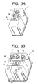
- Figs. 3A and 3B show one embodiment of the black ink cartridge 1 and one embodiment of the color ink cartridge 2, respectively.
- the black ink cartridge 1 has, on a surface thereof opposite to the carriage 11 when it is mounted on the carriage 11, in this embodiment, on a bottom surface 30 thereof, an ink supply port 31 connectable to an ink guide passage of the recording head 17, and memory means 32, such as EEPROM that is a rewritable nonvolatile memory.
- the color ink cartridge 2 is divided into a plurality of rooms that store individually a plurality of color ink therein.
- ink supply ports 41, 42 and 43 which are communicated with respective ink chambers and can be connected to the ink guide passage of the recording head 18, and also memory means 44, such as EEPROM that is a rewritable nonvolatile memory.
- These memory means 32 and 44 provided for the ink cartridges 1 and 2 are mounted on substrates 27 and 28, and connected to control means 53 to be described later through contacts 33 and 45 connected to said memory means 32 and 44 by contacts 34 and 46 formed at the carriage, so that data stored in these memory means 32 and 44 are read or data of the memory means in a main body of the recording apparatus is written.
- Each memory means of the ink cartridges of the invention has at least the following data relating to the ink cartridge.
- data is stored with a data format that can be recognized by the recording apparatus main body or by a host computer connected to the recording apparatus.
- Fig. 4 shows one embodiment of a controlling device of the recording apparatus.
- the control device is so designed that in a state where the contacts 34 and 46 of the carriage 11 are connected to the contacts 33 and 45 of the ink cartridges 1 and 2, data reading and writing means 50 read the data in the memory means 32 and 44 of the ink cartridges 1 and 2 or write the data of the memory means provided for a recording device to be described later into the memory means 32 and 44 of the ink cartridges 1 and 2.
- Ink cartridge exchange judging means 51 receives signals from switches 35 and 47 that are located at positions of the carriage 11 opposite to the ink cartridges 1 and 2, in this embodiment on a cartridge receiving surface of the carriage 11, and that are push-operated by the ink cartridges 1 and 2, to thereby detect attachment and detachment of the ink cartridges 1 and 2.
- carriage motor controlling means 52 Upon reception of control from the controlling means 53, carriage motor controlling means 52 causes the carriage 11 to reciprocate for printing and also causes the recording heads 17 and 18 to move to positions where the recording heads 17 and 18 can be capped at the time of the ejection recovering operation.
- suction controlling means 54 Upon reception of control from the controlling means 53, suction controlling means 54 causes the recording heads 17 and 18 to be sealed by the capping unit 19, and causes pump driving means 55 to control suction force of each suction pump 23a, 23b and suction time thereof thereby to forcibly eject ink from the recording heads 17 and 18 for the purpose of recovery of ink ejecting capacity. Further, when the ink cartridges 1 and 2 are exchanged, the suction controlling means 54 fills ink into the recording heads 17 and 18 from the ink cartridges 1 and 2 so that the printing operation can be performed.
- Printing/flashing control means 56 causes head driving means 57 to output driving signals for ejecting ink droplets to each of the recording heads 17 and 18 based an the print data from the host, thereby to execute printing. Further, when each of recording heads 17 and 18 is located at a flushing position (for example, a position opposite to the cap), the means 56 causes the ink droplets to be ejected from all of nozzle openings by outputting the similar driving signals as the aforesaid signals, so that the viscosity-increased ink is ejected to the cap serving as an ink reception member.
- Residual ink amount detecting means 58 adds up the number of dots formed by the printing operation, the number of the ink droplets ejected by the flashing operation, and the amount of ink consumed by the filling operation and the cleaning operation to calculate the amount of the residual ink in the ink cartridges 1 and 2.
- Power-break detecting means 59 detects on/off of the power switch 5 and outputs signals indicative of that state. Further, when apower-off Operation is performed, after the predetermined following operations have been executed, the means 59 stops power-supply to the apparatus.
- the control means 53 receives signals from the ink cartridge exchanging instruction-switch 6 of the panel 4, the cleaning instruction switches 7 and 8 of the panel 4, the power-break detecting means 59, the residual ink amount detecting means 58 and the host, and generalizes operations, such as a power-on operation, a power-off operation, a cleaning operation, a residual ink amount checking operation, a printing operation and an ink cartridge exchanging operation. Further, the control means 53 stores, in the memory means 63, various statuses associated with the exchange of the ink cartridge at the time of the power-off operation.
- control means 53 receives signals from a paper-supply error detecting section 62 for detecting paper-supply error such as paper-jam, and an ejection error detecting section 63 for detecting ejection error of ink droplets, and performs an error displaying operation.
- This ink cartridge 1, 2 and the recording apparatus aim to continue the high quality recording operation of a high quality by supplying the optimum ink from the ink cartridge 1, 2 mounted in the recording apparatus to the recording apparatus, and are featured in that, when a problem such as the print error occurs, the recording apparatus reads data of the memory means 32, 44 of the ink cartridge 1, 2, and informs an Operator of a main cause of the problem to promote the execution of the corresponding countermeasures.
- the ink cartridges 1, 2 are mounted an the carriage 11 serving as a mounting Portion of the recording apparatus, and the ink supplying portions 31, 41, 42, 43 are communicated with the recording heads 17, 18 to enter a stand-by state for ink supply (S1).
- the memory means 32, 44 are connected to respective contact portions 34, 46 of the recording apparatus so that the kind data (c) of the data stored in the memory means 32, 44 is read-out by the data reading and writing means 50, and compared by the control means 53 with the designated ink cartridge data retrieved from the memory means 60, whereby compatibility of the ink cartridges 1, 2 to the recording apparatus is judged (S2). If the ink cartridge 1, 2 is not compatible to the recording apparatus, the incompatibility is displayed in the displays 9, 10 to give an alarm to the operator (S3), and a starting operation of the recording apparatus is restrained (S4).
- the date data is recorded in the memory means 60 (S5), and when a recording instruction is given by operation means (not shown), ink supplied from ink storage portion of the ink cartridge 1, 2 is supplied from the ink supplying portion to the recording head portion, whereby the desired recording operation is executed (S6).
- the recording apparatus records, in the memory means 60, time point at which the recovery operation such as a suction operation for sucking ink from the recording head has been performed (S8).
- the control section 53 calculates elapsed time based an time data of a timer means 61 and the recovery operation time point data of the memory means 60, and compares the elapsed time with standard recovery interval data of the memory means 60 (S9).
- a normal recovery operation S10 is executed, while in case that the predetermined time does not elapse, the data reading and writing means 50 reads out data of the manufacturing date from the memory means 32, 44 and retrieves data of an effective period of use from the memory means 60 so that the control section 53 judges whether the effective period of use has been passed (S11). If passed, the display sections 9, 10 display the passing of the effective period of use (S12), and then the procedure proceeds to step S13.
- mounting data is retrieved from the memory means 60 and compared with time point data of the timer 61 by the control section 53 (S13).
- the display sections 9, 10 display similarly the passing of the effective period of use (S14) and then the procedure proceeds to a step S15.
- destination data corresponding to this ink cartridge 1, 2 is read out by the data reading and writing means 50 from the memory means 32, 44, and compared with the designated ink cartridge data of the recording means 60 by the control section 53 (S15).
- the display sections 9, 10 display the incompatibility (S16).
- the effective countermeasure as described above makes it possible to eliminate operation error and damage of the recording apparatus caused by the ink cartridge.
- the display means As the display means, the display members 9 and 10 disposed in the case 3 are used, however, the indication and the alarm may be conducted on a host computer connected to the recording apparatus. In this case, more detailed data can be displayed than that in the display member of the recording apparatus, and can be also informed by voice.
- the data to be informed may be printed on a paper medium.
- This method can be utilized in case that there is no display member, and even in case that there is a display member, this method can inform more detailed data.
- the informed data is stored in the memory means 60 of the recording apparatus for a predetermined period, whereby it can be utilized as the data for exchanging the cartridge by taking out the stored data according to the circumstances.
- a recording apparatus using an on-carriage type ink cartridge which mounts an ink cartridge on a carriage
- a recording apparatus has been described as a recording apparatus.
- the invention can be applied to a recording apparatus using an off-carriage type ink cartridge, in which an ink cartridge is attached to a main body, i.e. a portion other than a carriage, of the apparatus, and ink is supplied to a recording head by a tube.
- a main cause of problem on the recording operation due to the ink cartridge mounted on the recording apparatus can be recognized precisely, so that the corresponding operation for solving the problem can be rapidly executed.
Abstract
Description
- The present invention relates to a recording apparatus and its ink cartridge capable of supplying ink to printing means of the ink jet recording apparatus such as an ink jet printer.
- This type of a conventional printing apparatus has been disclosed in, for example,
JP-A-8-248839 - In the known example, a recording method is changed based an data from the memory so as to effectively perform a printing operation.
- However, in this known example, the data of the memory is utilized solely for the purpose of changing the recording method.
- Further,
US-A-5 049 898 andEP-A-0 854 043 disclose a recording apparatus according to the preamble ofclaim 1. - A first problem that the invention is to solve is to provide what can judge availability of an ink cartridge and compatibility thereof to the recording apparatus based an data of memory means provided to the ink cartridge and notify a user of them.
- A second problem that the invention is to solve is to provide what can rapidly remove a cause of abnormal state such as print error in the recording apparatus.
- A third problem that the invention is to solve is to provide what causes an user to precisely know a stable using state of the ink cartridge, a stable using state between the ink cartridge and the recording apparatus, etc. and to suitably adopt them.
- These problems are solved according to the invention by a recording apparatus according to
claims -
- Fig. 1 is a diagram showing one embodiment of an ink jet recording apparatus of the present invention.
- Fig. 2 is a diagram showing one embodiment of a recording mechanism of the ink jet recording apparatus of the invention.
- Figs. 3A and 3B are diagrams each showing one embodiment of an ink cartridge used in the ink jet recording apparatus of the invention.
- Fig. 4 is a constitutional view showing one embodiment of the ink jet recording apparatus of the invention.
- Figs. 5 and 6 are flowcharts according to a first aspect of the invention.
- Preferred embodiments of the invention will be described below based on the Figures.
- Fig. 1 shows one embodiment of an ink jet recording apparatus of the invention, in which
ink cartridges case 3. - On an exposed surface of the
case 3, anOperation panel 4 is provided, on which there are arranged apower switch 5, an ink cartridge exchanging instruction-switch 6, a black head cleaning instruction-switch 7, a color head cleaning instruction-switch 8, and displays 9,10 such as LEDs that are turned on and off or turned on when ink in a black cartridge and a color ink cartridge ends or an error occurs. - Fig. 2 shows a summary of the printing mechanism. A
carriage 11 is connected to acarriage driving motor 13 through atiming Belt 12 and constructed so as to reciprocate in parallel with aplaten 15 while being guide by aguide member 14. In thecarriage 11, arecording head 17 which ejects black ink is fixed on a printing region side (in the figure, on the left side) of its surface opposite to arecording sheet 16, and arecording head 18 which ejects a color ink is fixed on non-printing region side (in the figure, on the right side) of the same. - A
capping unit 19 disposed at the non-printing region is provided with a slider on which acap 20 for sealing the blackink recording head 17 and acap 21 for sealing the colorink recording head 18 are mounted, and each of the caps is connected through a tube to aduplex pump unit 23 which is driven by amotor 22, and constructed so as to individually receive supply of a negative pressure. - Each of the
caps recording head caps recording heads recording heads pump unit 23 at the time of a recovery operation of ejecting capacity or at the time of exchange of theink cartridges 7 and 8. Further, in the vicinity of thecapping unit 19, acleaning unit 24 is disposed, which brings a wiping blade into contact with the nozzle opening surfaces of therecording heads - Figs. 3A and 3B show one embodiment of the
black ink cartridge 1 and one embodiment of thecolor ink cartridge 2, respectively. Theblack ink cartridge 1 has, on a surface thereof opposite to thecarriage 11 when it is mounted on thecarriage 11, in this embodiment, on abottom surface 30 thereof, anink supply port 31 connectable to an ink guide passage of therecording head 17, and memory means 32, such as EEPROM that is a rewritable nonvolatile memory. - The
color ink cartridge 2 is divided into a plurality of rooms that store individually a plurality of color ink therein. On abottom surface 40 of thecolor ink cartridge 2, there are providedink supply ports recording head 18, and also memory means 44, such as EEPROM that is a rewritable nonvolatile memory. - These memory means 32 and 44 provided for the
ink cartridges substrates control means 53 to be described later throughcontacts contacts - Each memory means of the ink cartridges of the invention has at least the following data relating to the ink cartridge. As a data storage mode, data is stored with a data format that can be recognized by the recording apparatus main body or by a host computer connected to the recording apparatus.
- (a) Kind of data
Kind (type number) of ink cartridge - (b) Recovery data
Data at the time of the preceding recovery operation - (c) Manufacturing data
At least data of year and month when the ink cartridge has been manufactured is stored, and also data of date and time when the ink cartridge has been manufactured can be stored. - (d) Mounting data
Data of at least year and month when the ink cartridge has been mounted - (e) Destination data
Destination data such as corresponding areas or corresponding countries of the ink cartridge - Fig. 4 shows one embodiment of a controlling device of the recording apparatus. The control device is so designed that in a state where the
contacts carriage 11 are connected to thecontacts ink cartridges ink cartridges ink cartridges - Ink cartridge exchange judging means 51 receives signals from
switches carriage 11 opposite to theink cartridges carriage 11, and that are push-operated by theink cartridges ink cartridges - Upon reception of control from the controlling
means 53, carriage motor controlling means 52 causes thecarriage 11 to reciprocate for printing and also causes therecording heads recording heads - Upon reception of control from the controlling
means 53, suction controlling means 54 causes therecording heads capping unit 19, and causes pump driving means 55 to control suction force of eachsuction pump recording heads ink cartridges recording heads ink cartridges - Printing/flashing control means 56 causes head driving means 57 to output driving signals for ejecting ink droplets to each of the
recording heads recording heads means 56 causes the ink droplets to be ejected from all of nozzle openings by outputting the similar driving signals as the aforesaid signals, so that the viscosity-increased ink is ejected to the cap serving as an ink reception member. - Residual ink amount detecting means 58 adds up the number of dots formed by the printing operation, the number of the ink droplets ejected by the flashing operation, and the amount of ink consumed by the filling operation and the cleaning operation to calculate the amount of the residual ink in the
ink cartridges - Power-break detecting means 59 detects on/off of the
power switch 5 and outputs signals indicative of that state. Further, when apower-off Operation is performed, after the predetermined following operations have been executed, themeans 59 stops power-supply to the apparatus. - The control means 53 receives signals from the ink cartridge exchanging instruction-
switch 6 of thepanel 4, thecleaning instruction switches 7 and 8 of thepanel 4, the power-break detecting means 59, the residual ink amount detecting means 58 and the host, and generalizes operations, such as a power-on operation, a power-off operation, a cleaning operation, a residual ink amount checking operation, a printing operation and an ink cartridge exchanging operation. Further, the control means 53 stores, in the memory means 63, various statuses associated with the exchange of the ink cartridge at the time of the power-off operation. Moreover, the control means 53 receives signals from a paper-supplyerror detecting section 62 for detecting paper-supply error such as paper-jam, and an ejectionerror detecting section 63 for detecting ejection error of ink droplets, and performs an error displaying operation. - This
ink cartridge ink cartridge ink cartridge - Next, operations of this ink cartridge and recording apparatus will be described with reference to flowcharts shown in Figs. 5 and 6.
- The
ink cartridges carriage 11 serving as a mounting Portion of the recording apparatus, and theink supplying portions - In this state, the memory means 32, 44 are connected to
respective contact portions ink cartridges ink cartridge displays - If it is judged that the
ink cartridge ink cartridge - Next, when the operator requires the recovery operation of the recording head according to the necessity as the recording operation processes (S7), the recording apparatus records, in the memory means 60, time point at which the recovery operation such as a suction operation for sucking ink from the recording head has been performed (S8).
- After the recovery operation has been thus executed suitably, the
control section 53 calculates elapsed time based an time data of a timer means 61 and the recovery operation time point data of the memory means 60, and compares the elapsed time with standard recovery interval data of the memory means 60 (S9). In case that a predetermined time elapses, a normal recovery operation (S10) is executed, while in case that the predetermined time does not elapse, the data reading and writing means 50 reads out data of the manufacturing date from the memory means 32, 44 and retrieves data of an effective period of use from the memory means 60 so that thecontrol section 53 judges whether the effective period of use has been passed (S11). If passed, thedisplay sections - Sequentially, mounting data is retrieved from the memory means 60 and compared with time point data of the
timer 61 by the control section 53 (S13). - As a consequence of this comparison, if the time elapsed from the mounting date exceeds the effective period of use, the
display sections - Next, destination data corresponding to this
ink cartridge display sections - Then, the recovery operation for abnormal state is executed (S17), and the procedure returns to the recording operation (S6).
- All of the elapsed time data confirmed by the recording apparatus (S9, S11 and S13) during this procedure is informed of the memory means 32, 44 of the
ink cartridge ink cartridges - According to this ink cartridge and recording apparatus described above, a main cause of abnormal state which continuously requires the recovery operation is precisely informed of the operator by the display section, so that the operator can rapidly and correctly execute the operation for solving the problem.
- Further, the effective countermeasure as described above makes it possible to eliminate operation error and damage of the recording apparatus caused by the ink cartridge.
- As the display means, the
display members case 3 are used, however, the indication and the alarm may be conducted on a host computer connected to the recording apparatus. In this case, more detailed data can be displayed than that in the display member of the recording apparatus, and can be also informed by voice. - As another informing method, the data to be informed may be printed on a paper medium. This method can be utilized in case that there is no display member, and even in case that there is a display member, this method can inform more detailed data.
- Further, the informed data is stored in the memory means 60 of the recording apparatus for a predetermined period, whereby it can be utilized as the data for exchanging the cartridge by taking out the stored data according to the circumstances.
- Further, a recording apparatus using an on-carriage type ink cartridge, which mounts an ink cartridge on a carriage, has been described as a recording apparatus. However, the invention can be applied to a recording apparatus using an off-carriage type ink cartridge, in which an ink cartridge is attached to a main body, i.e. a portion other than a carriage, of the apparatus, and ink is supplied to a recording head by a tube.
- Effects of the above-described invention is as follows:
- A main cause of problem on the recording operation due to the ink cartridge mounted on the recording apparatus can be recognized precisely, so that the corresponding operation for solving the problem can be rapidly executed.
- Further, damage of the recording apparatus caused by the ink cartridge can be eliminated preliminarily.
Claims (4)
- A recording apparatus comprising
an ink cartridge (1, 2) provided with memory means (32, 44) that stores data relating to the ink cartridge (1, 2), said data being indicative of a manufacturing year and a manufacturing month of the ink cartridge;
a recording head (17) that performs a recording operation with ink supplied from the ink cartridge; and
control means (53) adapted to read, write and rewrite the data stored in the memory means (32, 44) of said ink cartridge (1, 2), such that in case that abnormality has occurred in the recording apparatus, information can be notified based on the data stored in the memory means of said ink cartridge,
characterized in that
the control means (53) is adapted to calculate a period elapsed from said manufacturing year and manufacturing month to the time point when the abnormality has occurred in the apparatus in case that the abnormality has occurred in the recording apparatus, and to notify, in case that the elapsed period exceeds an effective period of use, the information that the elapsed period exceeds the effective period of use. - A recording apparatus comprising
an ink cartridge (1, 2) provided with memory means (32, 44) that stores data relating to the ink cartridge (1, 2), wherein said data is indicative of a mounting year and a mounting month of the ink cartridge which the recording apparatus wrote in the memory means (32, 44) of the ink cartridge when the ink cartridge (1, 2) was mounted to the recording apparatus;
a recording head (17) that performs a recording operation with ink supplied from the ink cartridge; and
control means (53) adapted to read, write and rewrite the data stored in the memory means (32, 44) of said ink cartridge, such that in case that abnormality has occurred in the recording apparatus, information can be notified based on the data stored in the memory means of said ink cartridge,
characterized in that
the control means (53) is adapted to calculate a period elapsed from said mounting year and mounting month to the time point when the abnormality has occurred in the apparatus in case that an abnormality has occurred in the recording apparatus, and to notify, in case that the elapsed period exceeds an effective period of use, the information that the elapsed period exceeds an effective period of use. - The recording apparatus according to claim 1 or 2, wherein said data is further indicative of a kind of the ink cartridge; the control means (53) is adapted to judge whether or not said data indicative of the kind of ink cartridge can be used in the recording apparatus, and in case that it cannot be used, to stop an operation of the recording apparatus and to notify the information that the ink cartridge cannot be used.
- The recording apparatus according to any of claims 1 to 3, wherein said data is further indicative of a destination of the ink cartridge; the control means (53) is adapted to judge whether or not said data indicative of the destination of the ink cartridge is suitable for the recording apparatus in case that abnormality has occurred in the recording apparatus, and in case that it is not suitable, to notify the information that the ink cartridge is not suitable for use with the recording apparatus to a user.
Applications Claiming Priority (3)
| Application Number | Priority Date | Filing Date | Title |
|---|---|---|---|
| JP26005298 | 1998-09-14 | ||
| JP26005298 | 1998-09-14 | ||
| PCT/JP1999/005002 WO2000015441A1 (en) | 1998-09-14 | 1999-09-13 | Ink cartridge and recorder |
Publications (3)
| Publication Number | Publication Date |
|---|---|
| EP1031426A1 EP1031426A1 (en) | 2000-08-30 |
| EP1031426A4 EP1031426A4 (en) | 2002-04-03 |
| EP1031426B1 true EP1031426B1 (en) | 2007-12-05 |
Family
ID=17342646
Family Applications (1)
| Application Number | Title | Priority Date | Filing Date |
|---|---|---|---|
| EP99943325A Expired - Lifetime EP1031426B1 (en) | 1998-09-14 | 1999-09-13 | Ink cartridge and recorder |
Country Status (6)
| Country | Link |
|---|---|
| US (1) | US6431680B1 (en) |
| EP (1) | EP1031426B1 (en) |
| JP (1) | JP3584880B2 (en) |
| AT (1) | ATE380113T1 (en) |
| DE (1) | DE69937669D1 (en) |
| WO (1) | WO2000015441A1 (en) |
Families Citing this family (13)
| Publication number | Priority date | Publication date | Assignee | Title |
|---|---|---|---|---|
| GB9821787D0 (en) * | 1998-10-06 | 1998-12-02 | Data Limited | Apparatus for classifying or processing data |
| JP4632140B2 (en) * | 2000-04-11 | 2011-02-16 | セイコーエプソン株式会社 | Liquid ejector |
| US7014286B2 (en) | 2000-04-11 | 2006-03-21 | Seiko Epson Corporation | Liquid jetting apparatus |
| JP2002160387A (en) * | 2000-09-12 | 2002-06-04 | Canon Inc | Media pack, printer, and camera with printer |
| JP4274453B2 (en) * | 2001-07-02 | 2009-06-10 | 横浜ゴム株式会社 | Vehicle tire monitoring system |
| US6896350B2 (en) * | 2001-10-31 | 2005-05-24 | Hewlett-Packard Development Company, L.P. | Optimized servicing that adapts preventative and corrective actions to the life of a printhead |
| KR100444574B1 (en) * | 2002-01-18 | 2004-08-16 | 삼성전자주식회사 | Inkjet printer and Maintenance control method of the same |
| JP2005088423A (en) * | 2003-09-18 | 2005-04-07 | Olympus Corp | Image forming device and treatment method during power-off |
| US7334886B2 (en) * | 2004-07-02 | 2008-02-26 | Hilord Chemical Corporation | Bulk ink delivery system for ink jet printers and the like |
| US20060103701A1 (en) * | 2004-11-17 | 2006-05-18 | Nu-Kote International, Inc. | Ink cartridge with semiconductor storage device |
| WO2006060541A2 (en) | 2004-11-30 | 2006-06-08 | Panduit Corp. | Market-based labeling system and method |
| JP4533127B2 (en) * | 2004-12-24 | 2010-09-01 | キヤノン株式会社 | Ink storage container |
| JP5538924B2 (en) * | 2009-03-19 | 2014-07-02 | キヤノン株式会社 | Printing apparatus and sheet processing apparatus control method |
Family Cites Families (11)
| Publication number | Priority date | Publication date | Assignee | Title |
|---|---|---|---|---|
| US5049898A (en) * | 1989-03-20 | 1991-09-17 | Hewlett-Packard Company | Printhead having memory element |
| JP2962838B2 (en) * | 1991-01-18 | 1999-10-12 | キヤノン株式会社 | Ink jet recording device |
| JPH04275156A (en) * | 1991-03-01 | 1992-09-30 | Tokyo Electric Co Ltd | Ink jet printer and ink jet cartridge therefor |
| JPH05169670A (en) * | 1991-12-25 | 1993-07-09 | Canon Inc | Ink cartridge |
| JPH06320732A (en) * | 1993-05-17 | 1994-11-22 | Canon Inc | Ink jet recorder |
| US5812156A (en) * | 1997-01-21 | 1998-09-22 | Hewlett-Packard Company | Apparatus controlled by data from consumable parts with incorporated memory devices |
| US5491540A (en) | 1994-12-22 | 1996-02-13 | Hewlett-Packard Company | Replacement part with integral memory for usage and calibration data |
| JPH08310007A (en) * | 1995-05-19 | 1996-11-26 | Oki Data:Kk | Serial printer |
| FR2744391B1 (en) * | 1996-02-01 | 1998-03-06 | Imaje Sa | INDUSTRIAL PRINTER CAPABLE OF RECEIVING AT LEAST ONE CONSUMABLE CARTRIDGE |
| US6106088A (en) * | 1997-10-01 | 2000-08-22 | Xerox Corporation | Printhead assembly with integral lifetime monitoring system |
| JPH11240185A (en) * | 1998-02-25 | 1999-09-07 | Konica Corp | Image formation apparatus and color material cartridge |
-
1999
- 1999-09-13 DE DE69937669T patent/DE69937669D1/en not_active Expired - Lifetime
- 1999-09-13 AT AT99943325T patent/ATE380113T1/en not_active IP Right Cessation
- 1999-09-13 WO PCT/JP1999/005002 patent/WO2000015441A1/en active IP Right Grant
- 1999-09-13 JP JP2000570007A patent/JP3584880B2/en not_active Expired - Fee Related
- 1999-09-13 EP EP99943325A patent/EP1031426B1/en not_active Expired - Lifetime
-
2000
- 2000-05-15 US US09/571,331 patent/US6431680B1/en not_active Expired - Fee Related
Also Published As
| Publication number | Publication date |
|---|---|
| EP1031426A4 (en) | 2002-04-03 |
| EP1031426A1 (en) | 2000-08-30 |
| DE69937669D1 (en) | 2008-01-17 |
| JP3584880B2 (en) | 2004-11-04 |
| WO2000015441A1 (en) | 2000-03-23 |
| US6431680B1 (en) | 2002-08-13 |
| ATE380113T1 (en) | 2007-12-15 |
Similar Documents
| Publication | Publication Date | Title |
|---|---|---|
| US6338539B1 (en) | Ink jet recording device | |
| US6361138B1 (en) | Ink jet printing apparatus and ink cartridge | |
| JP3250556B2 (en) | Ink jet printing apparatus, method for accessing memory device of ink cartridge, and method for controlling printing apparatus | |
| JP3755755B2 (en) | An ink cartridge, an ink jet recording apparatus using the ink cartridge, and a method for determining whether an ink cartridge can be attached to the apparatus. | |
| KR970007627B1 (en) | Inkjet recording apparatus and ink tank | |
| EP1031426B1 (en) | Ink cartridge and recorder | |
| EP1775132B1 (en) | Identification of container for printing recording material | |
| US8038253B2 (en) | Ink jet recording apparatus and maintenance method thereof | |
| JP3613313B2 (en) | Inkjet recording device | |
| EP1038682B1 (en) | Ink-jet recorder | |
| US20020135630A1 (en) | Ink-jet printer | |
| JPH10211719A (en) | Ink jet recording apparatus | |
| JP3287399B2 (en) | Ink jet recording device | |
| JP2005224980A (en) | Liquid vessel and liquid consumption device | |
| JP3839517B2 (en) | Inkjet printer | |
| JP2007118339A (en) | Inkjet printer, method for restoring function of inkjet printer, and program | |
| JP4292510B2 (en) | Liquid ejector | |
| JP2003011387A (en) | Ink cartridge | |
| JP2001071471A (en) | Ink jet recording device | |
| JP2003127423A (en) | Ink-jet recording apparatus and method for setting ink- cartridge mounting position in the apparatus | |
| JPH08174974A (en) | Ink jet recording device | |
| JP2006137123A (en) | Inkjet printer, function recovery control method of inkjet printer and program | |
| JP2000085147A (en) | Ink-jet recording apparatus | |
| JP2002160382A (en) | Maintenance kit for ink jet recording device |
Legal Events
| Date | Code | Title | Description |
|---|---|---|---|
| PUAI | Public reference made under article 153(3) epc to a published international application that has entered the european phase |
Free format text: ORIGINAL CODE: 0009012 |
|
| 17P | Request for examination filed |
Effective date: 20000512 |
|
| AK | Designated contracting states |
Kind code of ref document: A1 Designated state(s): AT BE CH CY DE DK ES FI FR GB GR IE IT LI LU MC NL PT SE |
|
| A4 | Supplementary search report drawn up and despatched |
Effective date: 20020220 |
|
| AK | Designated contracting states |
Kind code of ref document: A4 Designated state(s): AT BE CH CY DE DK ES FI FR GB GR IE IT LI LU MC NL PT SE |
|
| 17Q | First examination report despatched |
Effective date: 20050601 |
|
| GRAP | Despatch of communication of intention to grant a patent |
Free format text: ORIGINAL CODE: EPIDOSNIGR1 |
|
| GRAS | Grant fee paid |
Free format text: ORIGINAL CODE: EPIDOSNIGR3 |
|
| GRAA | (expected) grant |
Free format text: ORIGINAL CODE: 0009210 |
|
| AK | Designated contracting states |
Kind code of ref document: B1 Designated state(s): AT BE CH CY DE DK ES FI FR GB GR IE IT LI LU MC NL PT SE |
|
| REG | Reference to a national code |
Ref country code: GB Ref legal event code: FG4D |
|
| REG | Reference to a national code |
Ref country code: IE Ref legal event code: FG4D |
|
| REG | Reference to a national code |
Ref country code: CH Ref legal event code: EP |
|
| REF | Corresponds to: |
Ref document number: 69937669 Country of ref document: DE Date of ref document: 20080117 Kind code of ref document: P |
|
| PG25 | Lapsed in a contracting state [announced via postgrant information from national office to epo] |
Ref country code: SE Free format text: LAPSE BECAUSE OF FAILURE TO SUBMIT A TRANSLATION OF THE DESCRIPTION OR TO PAY THE FEE WITHIN THE PRESCRIBED TIME-LIMIT Effective date: 20080305 Ref country code: NL Free format text: LAPSE BECAUSE OF FAILURE TO SUBMIT A TRANSLATION OF THE DESCRIPTION OR TO PAY THE FEE WITHIN THE PRESCRIBED TIME-LIMIT Effective date: 20071205 Ref country code: LI Free format text: LAPSE BECAUSE OF FAILURE TO SUBMIT A TRANSLATION OF THE DESCRIPTION OR TO PAY THE FEE WITHIN THE PRESCRIBED TIME-LIMIT Effective date: 20071205 Ref country code: ES Free format text: LAPSE BECAUSE OF FAILURE TO SUBMIT A TRANSLATION OF THE DESCRIPTION OR TO PAY THE FEE WITHIN THE PRESCRIBED TIME-LIMIT Effective date: 20080316 Ref country code: CH Free format text: LAPSE BECAUSE OF FAILURE TO SUBMIT A TRANSLATION OF THE DESCRIPTION OR TO PAY THE FEE WITHIN THE PRESCRIBED TIME-LIMIT Effective date: 20071205 |
|
| PG25 | Lapsed in a contracting state [announced via postgrant information from national office to epo] |
Ref country code: FI Free format text: LAPSE BECAUSE OF FAILURE TO SUBMIT A TRANSLATION OF THE DESCRIPTION OR TO PAY THE FEE WITHIN THE PRESCRIBED TIME-LIMIT Effective date: 20071205 |
|
| NLV1 | Nl: lapsed or annulled due to failure to fulfill the requirements of art. 29p and 29m of the patents act | ||
| REG | Reference to a national code |
Ref country code: CH Ref legal event code: PL |
|
| PG25 | Lapsed in a contracting state [announced via postgrant information from national office to epo] |
Ref country code: AT Free format text: LAPSE BECAUSE OF FAILURE TO SUBMIT A TRANSLATION OF THE DESCRIPTION OR TO PAY THE FEE WITHIN THE PRESCRIBED TIME-LIMIT Effective date: 20071205 |
|
| PG25 | Lapsed in a contracting state [announced via postgrant information from national office to epo] |
Ref country code: BE Free format text: LAPSE BECAUSE OF FAILURE TO SUBMIT A TRANSLATION OF THE DESCRIPTION OR TO PAY THE FEE WITHIN THE PRESCRIBED TIME-LIMIT Effective date: 20071205 |
|
| PG25 | Lapsed in a contracting state [announced via postgrant information from national office to epo] |
Ref country code: PT Free format text: LAPSE BECAUSE OF FAILURE TO SUBMIT A TRANSLATION OF THE DESCRIPTION OR TO PAY THE FEE WITHIN THE PRESCRIBED TIME-LIMIT Effective date: 20080505 |
|
| EN | Fr: translation not filed | ||
| PLBE | No opposition filed within time limit |
Free format text: ORIGINAL CODE: 0009261 |
|
| STAA | Information on the status of an ep patent application or granted ep patent |
Free format text: STATUS: NO OPPOSITION FILED WITHIN TIME LIMIT |
|
| PG25 | Lapsed in a contracting state [announced via postgrant information from national office to epo] |
Ref country code: DK Free format text: LAPSE BECAUSE OF FAILURE TO SUBMIT A TRANSLATION OF THE DESCRIPTION OR TO PAY THE FEE WITHIN THE PRESCRIBED TIME-LIMIT Effective date: 20071205 Ref country code: DE Free format text: LAPSE BECAUSE OF FAILURE TO SUBMIT A TRANSLATION OF THE DESCRIPTION OR TO PAY THE FEE WITHIN THE PRESCRIBED TIME-LIMIT Effective date: 20080306 |
|
| 26N | No opposition filed |
Effective date: 20080908 |
|
| PG25 | Lapsed in a contracting state [announced via postgrant information from national office to epo] |
Ref country code: GR Free format text: LAPSE BECAUSE OF FAILURE TO SUBMIT A TRANSLATION OF THE DESCRIPTION OR TO PAY THE FEE WITHIN THE PRESCRIBED TIME-LIMIT Effective date: 20080306 |
|
| REG | Reference to a national code |
Ref country code: HK Ref legal event code: WD Ref document number: 1032216 Country of ref document: HK |
|
| PG25 | Lapsed in a contracting state [announced via postgrant information from national office to epo] |
Ref country code: MC Free format text: LAPSE BECAUSE OF NON-PAYMENT OF DUE FEES Effective date: 20080930 Ref country code: FR Free format text: LAPSE BECAUSE OF FAILURE TO SUBMIT A TRANSLATION OF THE DESCRIPTION OR TO PAY THE FEE WITHIN THE PRESCRIBED TIME-LIMIT Effective date: 20081003 |
|
| PG25 | Lapsed in a contracting state [announced via postgrant information from national office to epo] |
Ref country code: IE Free format text: LAPSE BECAUSE OF NON-PAYMENT OF DUE FEES Effective date: 20080915 Ref country code: CY Free format text: LAPSE BECAUSE OF FAILURE TO SUBMIT A TRANSLATION OF THE DESCRIPTION OR TO PAY THE FEE WITHIN THE PRESCRIBED TIME-LIMIT Effective date: 20071205 |
|
| PG25 | Lapsed in a contracting state [announced via postgrant information from national office to epo] |
Ref country code: LU Free format text: LAPSE BECAUSE OF NON-PAYMENT OF DUE FEES Effective date: 20080913 |
|
| PGFP | Annual fee paid to national office [announced via postgrant information from national office to epo] |
Ref country code: GB Payment date: 20100908 Year of fee payment: 12 |
|
| PG25 | Lapsed in a contracting state [announced via postgrant information from national office to epo] |
Ref country code: IT Free format text: LAPSE BECAUSE OF NON-PAYMENT OF DUE FEES Effective date: 20080930 |
|
| GBPC | Gb: european patent ceased through non-payment of renewal fee |
Effective date: 20110913 |
|
| PG25 | Lapsed in a contracting state [announced via postgrant information from national office to epo] |
Ref country code: GB Free format text: LAPSE BECAUSE OF NON-PAYMENT OF DUE FEES Effective date: 20110913 |