EP1029805A1 - Partially shielded microwave heating container - Google Patents
Partially shielded microwave heating container Download PDFInfo
- Publication number
- EP1029805A1 EP1029805A1 EP00107706A EP00107706A EP1029805A1 EP 1029805 A1 EP1029805 A1 EP 1029805A1 EP 00107706 A EP00107706 A EP 00107706A EP 00107706 A EP00107706 A EP 00107706A EP 1029805 A1 EP1029805 A1 EP 1029805A1
- Authority
- EP
- European Patent Office
- Prior art keywords
- microwave
- shielded
- region
- top panel
- compartment
- Prior art date
- Legal status (The legal status is an assumption and is not a legal conclusion. Google has not performed a legal analysis and makes no representation as to the accuracy of the status listed.)
- Granted
Links
- 238000010438 heat treatment Methods 0.000 title claims abstract description 65
- 239000011087 paperboard Substances 0.000 claims abstract description 32
- 239000000463 material Substances 0.000 claims abstract description 27
- 230000002093 peripheral effect Effects 0.000 claims abstract description 6
- 239000000047 product Substances 0.000 description 17
- 239000011888 foil Substances 0.000 description 12
- 235000013305 food Nutrition 0.000 description 7
- 238000010276 construction Methods 0.000 description 6
- XAGFODPZIPBFFR-UHFFFAOYSA-N aluminium Chemical compound [Al] XAGFODPZIPBFFR-UHFFFAOYSA-N 0.000 description 4
- 229910052782 aluminium Inorganic materials 0.000 description 4
- 238000004519 manufacturing process Methods 0.000 description 3
- 230000005855 radiation Effects 0.000 description 3
- 239000006188 syrup Substances 0.000 description 3
- 235000020357 syrup Nutrition 0.000 description 3
- 235000013611 frozen food Nutrition 0.000 description 2
- 235000015243 ice cream Nutrition 0.000 description 2
- 235000021485 packed food Nutrition 0.000 description 2
- 230000015572 biosynthetic process Effects 0.000 description 1
- 239000012467 final product Substances 0.000 description 1
- 238000010030 laminating Methods 0.000 description 1
- 238000007639 printing Methods 0.000 description 1
- 239000010409 thin film Substances 0.000 description 1
Images


Classifications
-
- B—PERFORMING OPERATIONS; TRANSPORTING
- B65—CONVEYING; PACKING; STORING; HANDLING THIN OR FILAMENTARY MATERIAL
- B65D—CONTAINERS FOR STORAGE OR TRANSPORT OF ARTICLES OR MATERIALS, e.g. BAGS, BARRELS, BOTTLES, BOXES, CANS, CARTONS, CRATES, DRUMS, JARS, TANKS, HOPPERS, FORWARDING CONTAINERS; ACCESSORIES, CLOSURES, OR FITTINGS THEREFOR; PACKAGING ELEMENTS; PACKAGES
- B65D5/00—Rigid or semi-rigid containers of polygonal cross-section, e.g. boxes, cartons or trays, formed by folding or erecting one or more blanks made of paper
- B65D5/42—Details of containers or of foldable or erectable container blanks
- B65D5/44—Integral, inserted or attached portions forming internal or external fittings
- B65D5/48—Partitions
- B65D5/48002—Partitions integral
- B65D5/48018—Partitions integral formed by folding extensions of side panels of a "cross-like" body blank
-
- B—PERFORMING OPERATIONS; TRANSPORTING
- B65—CONVEYING; PACKING; STORING; HANDLING THIN OR FILAMENTARY MATERIAL
- B65D—CONTAINERS FOR STORAGE OR TRANSPORT OF ARTICLES OR MATERIALS, e.g. BAGS, BARRELS, BOTTLES, BOXES, CANS, CARTONS, CRATES, DRUMS, JARS, TANKS, HOPPERS, FORWARDING CONTAINERS; ACCESSORIES, CLOSURES, OR FITTINGS THEREFOR; PACKAGING ELEMENTS; PACKAGES
- B65D5/00—Rigid or semi-rigid containers of polygonal cross-section, e.g. boxes, cartons or trays, formed by folding or erecting one or more blanks made of paper
- B65D5/42—Details of containers or of foldable or erectable container blanks
- B65D5/64—Lids
- B65D5/66—Hinged lids
- B65D5/6626—Hinged lids formed by folding extensions of a side panel of a container body formed by erecting a "cross-like" blank
- B65D5/665—Hinged lids formed by folding extensions of a side panel of a container body formed by erecting a "cross-like" blank the lid being held in closed position by self-locking integral flaps or tabs
- B65D5/667—Lids in the form of an inverted tray
-
- B—PERFORMING OPERATIONS; TRANSPORTING
- B65—CONVEYING; PACKING; STORING; HANDLING THIN OR FILAMENTARY MATERIAL
- B65D—CONTAINERS FOR STORAGE OR TRANSPORT OF ARTICLES OR MATERIALS, e.g. BAGS, BARRELS, BOTTLES, BOXES, CANS, CARTONS, CRATES, DRUMS, JARS, TANKS, HOPPERS, FORWARDING CONTAINERS; ACCESSORIES, CLOSURES, OR FITTINGS THEREFOR; PACKAGING ELEMENTS; PACKAGES
- B65D81/00—Containers, packaging elements, or packages, for contents presenting particular transport or storage problems, or adapted to be used for non-packaging purposes after removal of contents
- B65D81/34—Containers, packaging elements, or packages, for contents presenting particular transport or storage problems, or adapted to be used for non-packaging purposes after removal of contents for packaging foodstuffs or other articles intended to be cooked or heated within the package
- B65D81/3446—Containers, packaging elements, or packages, for contents presenting particular transport or storage problems, or adapted to be used for non-packaging purposes after removal of contents for packaging foodstuffs or other articles intended to be cooked or heated within the package specially adapted to be heated by microwaves
- B65D81/3453—Rigid containers, e.g. trays, bottles, boxes, cups
-
- B—PERFORMING OPERATIONS; TRANSPORTING
- B65—CONVEYING; PACKING; STORING; HANDLING THIN OR FILAMENTARY MATERIAL
- B65D—CONTAINERS FOR STORAGE OR TRANSPORT OF ARTICLES OR MATERIALS, e.g. BAGS, BARRELS, BOTTLES, BOXES, CANS, CARTONS, CRATES, DRUMS, JARS, TANKS, HOPPERS, FORWARDING CONTAINERS; ACCESSORIES, CLOSURES, OR FITTINGS THEREFOR; PACKAGING ELEMENTS; PACKAGES
- B65D2581/00—Containers, packaging elements, or packages, for contents presenting particular transport or storage problems, or adapted to be used for non-packaging purposes after removal of contents
- B65D2581/34—Containers, packaging elements, or packages, for contents presenting particular transport or storage problems, or adapted to be used for non-packaging purposes after removal of contents for packaging foodstuffs or other articles intended to be cooked or heated within
- B65D2581/3437—Containers, packaging elements, or packages, for contents presenting particular transport or storage problems, or adapted to be used for non-packaging purposes after removal of contents for packaging foodstuffs or other articles intended to be cooked or heated within specially adapted to be heated by microwaves
- B65D2581/3471—Microwave reactive substances present in the packaging material
- B65D2581/3472—Aluminium or compounds thereof
-
- B—PERFORMING OPERATIONS; TRANSPORTING
- B65—CONVEYING; PACKING; STORING; HANDLING THIN OR FILAMENTARY MATERIAL
- B65D—CONTAINERS FOR STORAGE OR TRANSPORT OF ARTICLES OR MATERIALS, e.g. BAGS, BARRELS, BOTTLES, BOXES, CANS, CARTONS, CRATES, DRUMS, JARS, TANKS, HOPPERS, FORWARDING CONTAINERS; ACCESSORIES, CLOSURES, OR FITTINGS THEREFOR; PACKAGING ELEMENTS; PACKAGES
- B65D2581/00—Containers, packaging elements, or packages, for contents presenting particular transport or storage problems, or adapted to be used for non-packaging purposes after removal of contents
- B65D2581/34—Containers, packaging elements, or packages, for contents presenting particular transport or storage problems, or adapted to be used for non-packaging purposes after removal of contents for packaging foodstuffs or other articles intended to be cooked or heated within
- B65D2581/3437—Containers, packaging elements, or packages, for contents presenting particular transport or storage problems, or adapted to be used for non-packaging purposes after removal of contents for packaging foodstuffs or other articles intended to be cooked or heated within specially adapted to be heated by microwaves
- B65D2581/3486—Dielectric characteristics of microwave reactive packaging
- B65D2581/3489—Microwave reflector, i.e. microwave shield
-
- Y—GENERAL TAGGING OF NEW TECHNOLOGICAL DEVELOPMENTS; GENERAL TAGGING OF CROSS-SECTIONAL TECHNOLOGIES SPANNING OVER SEVERAL SECTIONS OF THE IPC; TECHNICAL SUBJECTS COVERED BY FORMER USPC CROSS-REFERENCE ART COLLECTIONS [XRACs] AND DIGESTS
- Y10—TECHNICAL SUBJECTS COVERED BY FORMER USPC
- Y10S—TECHNICAL SUBJECTS COVERED BY FORMER USPC CROSS-REFERENCE ART COLLECTIONS [XRACs] AND DIGESTS
- Y10S229/00—Envelopes, wrappers, and paperboard boxes
- Y10S229/902—Box for prepared or processed food
- Y10S229/903—Ovenable, i.e. disclosed to be placed in an oven
-
- Y—GENERAL TAGGING OF NEW TECHNOLOGICAL DEVELOPMENTS; GENERAL TAGGING OF CROSS-SECTIONAL TECHNOLOGIES SPANNING OVER SEVERAL SECTIONS OF THE IPC; TECHNICAL SUBJECTS COVERED BY FORMER USPC CROSS-REFERENCE ART COLLECTIONS [XRACs] AND DIGESTS
- Y10—TECHNICAL SUBJECTS COVERED BY FORMER USPC
- Y10S—TECHNICAL SUBJECTS COVERED BY FORMER USPC CROSS-REFERENCE ART COLLECTIONS [XRACs] AND DIGESTS
- Y10S229/00—Envelopes, wrappers, and paperboard boxes
- Y10S229/902—Box for prepared or processed food
- Y10S229/906—Baked goods
Definitions
- the present invention relates to a sectioned carton having a compartment which is shielded from microwave energy and another compartment which is exposed to microwave energy. More particularly, the invention pertains to a carton formed from a single blank of microwave permeable sheet material which is cut, scored and folded to form a multi-compartment container, wherein at least one section is coated with a material substantially impermeable by microwaves.
- Multi-compartment containers have been manufactured with a variety of constructions which allow portions of the container to be exposed to microwave energy while shielding other portions from the microwave energy. Many of these constructions, however, pertain to pre-packaged food products and do not allow the end user of the container to selectively place the food products into either shielded or non-shielded compartments in the container. Additionally, these constructions are often formed from separate components or materials for each compartment and must be assembled together to form the multi-compartment container.
- U.S. Patent No. 4,233,325 issued to Slangan et al. discloses one such microwaveable multi-compartment package.
- This package includes a lower compartment, containing frozen ice cream, which is substantially impermeable to microwave energy and an upper compartment, containing frozen syrup, which is microwave permeable.
- the package is placed in a microwave oven to melt the frozen syrup in the upper compartment.
- the two compartments are manufactured from separate cardboard blanks, formed and then fit together, wherein the upper compartment further includes a lip for easy removal of the upper compartment from the food package after microwave heating.
- an upper frozen food compartment permeable to microwave energy is provided with a lower frozen food compartment which is reflective of microwaves.
- the compartments are formed into U-shaped plastic compartments and joined together to form a single multi-compartment food package, and the two compartments must be further separated from one another after heating in order to access the food contained within the compartments.
- Both of the above-mentioned patents further are directed to pre-packaged frozen products, such as ice cream in the lower compartment and syrup in the upper compartment, wherein the upper and lower compartments are arranged vertically.
- U.S. Patent No. 4,081,646 issued to Goltsos discloses a multi-compartment heating container including a tray and cover which are thermoformed from plastic which is transparent to microwave energy.
- the outer surfaces of the tray and cover may be shielded against the microwave energy by a thin film of radiation-opaque material, except for the regions which are intended to define microwave-transparent openings
- Each compartment in this container is shielded against different amounts of microwave energy by leaving different sized windows on each compartment free from radiation-opaque material, wherein these windows are substantially identical to windows formed in the cover so that the windows in the cover will be in alignment with the windows on the tray.
- Canadian Patent CA-A-1 082 655 issued to Carlino discloses a microwave oven heating container made of a cardboard material.
- the side walls of the cardboard container are coated with a microwave reflecting material.
- Top and bottom walls of the container are only partially covered with printings of metallic ink being at least partially opaque to microwave radiation allowing different portions of microwave energy to penetrate to the inner part of the container to heat the food. This is in order to selectively heat different types of food with the proper amount of energy.
- a carton of the above-mentioned type which includes a microwave permeable compartment and a microwave shielded compartment, which is formed from a single microwave permeable blank having a portion of the blank laminated with a microwave shielding layer.
- a partially shielded microwave heating container which can be filled with a product by the end user of the package and does not need to be pre-packaged with a food product.
- Another object of the present invention is to provide a paperboard carton having a compartment which is permeable by microwave energy and another compartment which is reflective to microwave energy.
- Yet another object of the present invention is to provide a multi-compartment microwave heating carton having a compartment shielded against microwaves and a microwave permeable compartment wherein both compartments are formed from a single paperboard blank.
- It is yet another object of the present invention is to provide a microwave heating carton partially shielded against microwaves which is formed from a single paperboard blank laminated with a microwave reflective material on only a portion of the paperboard blank.
- Still another object of the present invention is to provide a multi-compartment microwave heating carton having a compartment shielded against microwaves and a microwave permeable compartment which does not need to be pre-packaged with a product and which allows the end user to place the products being used into the two compartments.
- the container comprises a first region and a second region.
- the first and second regions each include a top panel and a bottom surface.
- the bottom surface of each region has a peripheral edge and the bottom surface of the first region being defined by an area shielded from microwave energy commences along the peripheral edge and extends across less than the entire bottom surface.
- the second region being defined by the area of the bottom surface that is not shielded from microwave energy.
- the paperboard container further comprises a single bottom panel forming the bottom surface for both of the first and second regions and a plurality of side panels extending upwardly from the bottom panel and extending downwardly from the top panel.
- the first and second regions are formed from a unitary single sheet of microwave permeable paperboard material wherein the first region has a layer of microwave shielding material affixed to the single sheet of paperboard material.
- the microwave heating carton 10 of the present invention is formed from a single blank 12 of paperboard or similar microwave permeable sheet material, and the microwave heating container 10 is preferably formed in a clamshell-like shape.
- the blank 12 includes a top panel 14 and bottom panel 16 with the top panel flanked by end walls 18 and 20 and the bottom panel flanked by end walls 22 and 24.
- the top and bottom panels 14 and 16 are also flanked by side walls 26 and 28, and 30 and 32, respectively.
- the side walls 30 and 32 of the bottom panel 16 include extensions 34, 36, 38 and 40 attached thereto and joined to the side walls 30 and 32 by fold lines 42, 44, 46 and 48, respectively.
- Extensions 50, 52, 54 and 56 are attached to the end walls 18 and 20 of top panel 14 through fold lines 58, 60, 62 and 64.
- the carton blank 12 additionally has main body crease score lines 66 between side wall 26 and side wall 30 which form a pivotal axis between the top panel 14 and bottom panel 16 of the clamshell microwave heating container 10.
- the canon blank 12 further includes fold lines 68, 70, 72 and 74 between the top panel 14 and side walls 26 and 28 and end walls 18 and 20, and fold lines 76, 78, 80 and 82 between the bottom panel 16 and side walls 30 and 32 and end walls 22 and 24, respectively.
- the carton blank 12 further includes a shielding clamshell section 100 connected to the end wall 18 of the top panel 14 through fold line 101.
- a layer 102 of aluminum foil or similar material substantially impermeable by microwave energy is bonded to one surface of the shielding clamshell section 100 to provide a microwave shield.
- the foil layer 102 is bonded to the outer surface of the clamshell section 100.
- the foil layer 102 may alternatively be bonded to the inner surface of the clamshell section 100.
- the clamshell section 100 includes a top panel 104 joined by fold lines 106, 108, 110 and 112 to sidewalls 114, 116, 118 and 120, respectively.
- the clamshell section 100 has no bottom wall, for the bottom wall for the clamshell section 100 is provided by the bottom panel 14 of the microwave heating carton 10.
- the clamshell section 100 includes diagonal corner panels 122 and 124 joined to sidewalls 114 and 116 by crease score lines 126 and 128, wherein crease score lines 130 are also formed between corner panels 122 and 124.
- the clamshell section 100 further includes diagonal corner panels 132 and 134 joined to sidewalls 116 and 118 by crease score lines 136 and 138, wherein crease score lines 140 are also formed between corner panels 132 and 134.
- Fig. 2 the clamshell microwave heating container 10 is shown partially assembled and will be hereinafter described showing the construction of the package 10 having a microwave shielded section and a microwave heatable section.
- the clamshell section 100 is folded about fold line 101 so that the clamshell section 100 is positioned within the upper portion of the microwave heating container 10.
- the top panel 104 of clamshell section 100 is positioned adjacent to and substantially parallel to the top panel 14 of microwave heating container 10 with the foil layer 102 side of clamshell section 100 facing top panel 14.
- the width of top panel 104 is substantially the same as top panel 14 so that the fold lines 106, 110 and 112 of clamshell section 100 correspond to and overlie the fold lines 68, 70 and 72 attached to top panel 14. From the view shown in Fig.
- top panel 14 underlies sidewall 116 of shielded clamshell section 100
- side wall 26 underlies diagonal corner panels 122 and 124
- side wall 28 underlies diagonal corner panels 132 and 134.
- the top portion of the clamshell shape of the microwave heating container 10 is formed in this manner.
- the bottom portion of the clamshell shape is similarly formed.
- Side walls 30 and 32 are folded toward each other along fold lines 76 and 78 so that angles are now formed between side walls 30 and 32 and the bottom panel 16.
- End walls 22 and 24 are also folded toward each other along fold lines 80 and 82 so that angles are now formed between end walls 22 and 24 and the bottom panel 16, wherein extensions 34, 36, 38 and 40 are folded along fold lines 42, 44, 46 and 48 so that extensions 34 and 40 are adjacent to and substantially parallel to end wall 22 and extensions 36 and 38 are adjacent to and substantially parallel to end wall 24.
- crease score line 66 includes three parallel score lines with the two outside score lines providing a folding point for side walls 26 and 30 and the middle score line providing a pivotal folding axis between side walls 26 and 30.
- the microwave heating container With all of the end walls and side walls folded up in an assembled state, the microwave heating container resembles an open clamshell with top panel 14 and bottom panel 16 facing upward and positioned in substantially the same plane. This open position allows a plurality of semi-assembled microwave heating containers 10 to be stacked on top of each other and stored in this open position.
- the assembly of the microwave heating container 10 is completed by forming the separate microwave shielded and microwaveable sections. This is accomplished by folding the side wall 116 of clamshell section 100 along fold line toward the already folded end wall 120 and underlying end wall 18. As side wall 116 is folded upward, diagonal corner panels 122 and 124 are folded along fold line 130 so that the outer surfaces of corner panels 122 and 124 having the foil layer thereon face one another. Similarly, diagonal corner panels 132 and 134 are folded along fold line 140 so that the outer surfaces of corner panels 132 and 134 having the foil layer thereon face one another. The upwardly folded side wall 116 divides the top portion of the clamshell microwave heating container 10 into two sections.
- the side wall 26 is folded along crease score line 66 with respect to side wall 30 so that the upper portion of the clamshell microwave heating container 10 closes over the lower portion of the clamshell microwave heating container 10.
- the inner surface of top panel 14 faces downward toward the inner surface of bottom panel 16 when the clamshell microwave heating container 10 is in a closed position.
- This configuration allows a microwave shielded section as well as a microwave accessible section to be formed within the microwave heating container 10. Since the clamshell section 100 is coated with a microwave shielding foil layer 102, the portion of package 10 enclosed by clamshell section 100 forms the microwave shielded section.
- the microwave shielded section is enclosed by top panel 104, side walls 114, 116, 118, 120, 26, 28, 30 and 32, and bottom panel 16.
- the bottom portion of the microwave shielded section surrounded by bottom panel 16 and side walls 30 and 32 is permeable to microwave energy, because bottom panel 16 and side walls 30 and 32 are comprised of the microwave permeable paperboard described above and are not covered by a foil layer.
- the microwave energy will be applied from above the microwave heating container 10 and directed toward the top panel 14, wherein the bottom panel 16 of microwave heating container 10 will rest upon the bottom surface of the microwave heating apparatus so only a small fraction of microwaves emitted will actually pass through the bottom portion of the microwave shielded section of heating container 10. Therefore, a product may be placed within the microwave shielded section where the bottom portion of the product is intended to be heated while the top portion of the product is not intended to be heated, since the small amount of microwaves entering the bottom portion of the microwave shielded section will only heat that portion of a product adjacent to the bottom portion of the microwave shielded section.
- the non-shielded microwave section of the package 10 is enclosed by top panel 14, bottom panel 16, side walls 26, 28, 30, 32 and 116, and end wall 20.
- the non-shielded microwave section is divided from the microwave shielded section by a common dividing wall, side wall 116, wherein side wall 116 is the section of the non-shielded microwave section which is opaque to microwave radiation.
- the microwave heating container 10 may also employ a locking attachment which retains the heating container 10 in a closed state after top panel 14 is closed over bottom panel 16.
- the locking attachment is obtained by connecting hook-like projections 55 extending from extensions 52 and 54 with similar projections 57 extending from extensions 38 and 40.
- shaped projections 55a are formed on side wall 28 so that each projection 55 is aligned with projection 55a when extensions 52 and 54 are folded to lie adjacent to side wall 28.
- projections 57a are formed on end walls 22 and 24 so that each projection 57 is aligned with projection 57a when extensions 38 and 40 are folded to lie adjacent to end walls 22 and 24.
- This arrangement provides the projections 55 and 57 with a double-walled construction which gives the projections 55 and 57 added strength and support.
- the side wall 30 may also include ridges 90 formed therein to provide greater support along the direction of the ridges 90.
- the clamshell section 100, top panel 14, bottom panel 16 and all side walls are all formed from the same paperboard carton blank 12. Therefore, the above-described configuration provides a simple and efficient method of manufacturing a multi-compartment heating container 10 which allows one compartment to be heated by microwave energy while another compartment is substantially shielded from the microwave energy.
- the heating container is easily formed by laminating a portion of a paperboard blank 12, cutting the blank 12 into the desired shape, and forming the desired fold lines in the blank 12 so that it may be assembled into a multi-sectioned microwave heating container 10.
- This configuration allows multiple products to be placed into the heating container 10 and exposing the heating container 10 to microwave energy, while only the products in the non-shielded portion of the heating container 10 are actually heated by the microwave energy.
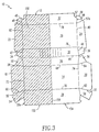
- FIG. 3 An alternative embodiment to the clamshell-shaped microwave heating container 10 is illustrated in Fig. 3, wherein the clamshell section 100 is eliminated from the embodiment described above in connection with Figs. 1 and 2.
- This embodiment provides an even simpler construction for a clamshell-shaped microwave heating container 10 having a microwave permeable section and a microwave shielded section. Unless specifically described otherwise, all of the components of this embodiment are substantially equivalent to the similarly numbered components of Figs. 1 and 2 and their descriptions need not be repeated.
- One-half of the paperboard blank 12 is laminated with a microwave reflective layer 150, such as aluminum foil or the like, and then cut and scored to form the microwave heating container 10 shown in Fig. 3 having a microwave shielded section 152 and a microwave permeable section 154.
- the foil layer 150 covers one-half of the length of the inside surfaces of the top panel 14, bottom panel 16, and side walls 26, 28, 30 and 32, while completely covering the inside surfaces of end walls 18 and 22 and extensions 34, 40, 50 and 52.
- the microwave heating container 10 is assembled exactly as described above, except that all of the sections of clamshell section 100 from Figs. 1 and 2 have been removed from this embodiment.
- top panel 14 and bottom panel oppose one another.
- the microwave shielded section 152 is enclosed by top panel 14, side walls 26, 28, 30 and 32, end walls 18 and 22, and bottom panel 16. Additionally, extensions 34, 40, 50 and 52 will also serve to enclose the microwave shielded section 152 since they are affixed to the inner laminated surfaces of end wall 18 and side walls 30 and 32, respectively.
- the microwave permeable section 154 is enclosed by top panel 14, side walls 26, 28, 30 and 32, end walls 20 and 24, bottom panel 16, and extensions 36, 38, 54 and 56.
- the microwave shielded section 152 will only be enclosed on five sides with the sixth side 156, the side lying in the plane between microwave shielded section 152 and microwave permeable section 154, being open to the microwave permeable section 154. With this embodiment, it is possible for microwaves to enter the microwave shielded section 152 through this open side 156 between the two sections 152 and 154. However, the microwave energy will be applied from above the microwave heating container 10 and directed toward the outer surface of top panel 14, wherein the bottom panel 16 of microwave heating container 10 will rest upon the bottom surface of the microwave heating apparatus and only a small fraction of microwaves emitted will actually pass through the open side 156 of microwave shielded section 152.
- microwaves In order for any microwaves to enter through open side 156, the microwaves must first pass through microwave permeable section 154 where the microwaves will encounter the product placed therein to be heated. Therefore, very few microwaves will actually enter into the microwave shielded section 152 through open side 156.
- the microwave heating container 10 may thus be sent to the end user in a partially assembled state where both the top panel 14 and bottom panel 16 facing upwards, where the end user need only place the desired products within the microwave shielded section 152 and microwave permeable section 154 and close the top panel 14 over the bottom panel 16.
- a plurality of microwave heating containers 10 may be stacked together in this partially assembled state and shipped to the end user in this manner.
- Fig. 4 illustrates a single blank 200 comprised of a microwave permeable material, such as paperboard, which includes a layer of microwave shielding material 202, such as aluminum foil, bonded to area on one end of the blank 200.
- the blank 200 is cut and scored as shown in Fig. 5 so that the blank 200 may be folded to form a microwave heating container 204 having two compartments, one compartment shielded from microwave energy and another compartment permeable by microwave energy.
- the microwave heating container 204 includes a bottom panel 206, side walls 208 and 210, end walls 212, 214, 216 and 218, and top panels 220 and 222.
- End walls 214 and 218 and top panel 220 are formed from the area with aluminum foil 202 bonded to the blank 200.
- the top panel 220 is flanked by end walls 214 and 218 and further flanked by side walls 224 and 226, while top panel 222 is flanked by end walls 212 and 216 and side walls 228 and 230.
- the end walls 212, 214, 216 and 218 include extensions 232, 234, 236, 238, 240, 242, 244 and 246 attached thereto through fold lines 248, 250, 252, 254, 256, 258, 260 and 262, respectively.
- the shielded compartment of microwave heating container 204 is assembled by folding side walls 208 and 210 toward one another until each side wall forms approximately a 90° angle with bottom panel 206. Extensions 236 and 238 are folded toward one another until each extension forms approximately a 90° angle with end wall 214. Similarly, side walls 224 and 226 are folded toward one another along fold lines 225 and 227 until the side walls 224 and 226 form approximately a 90° angle with top panel 220, and extensions 244 and 246 are folded toward one another until the extensions 244 and 246 form approximately a 90° angle with end wall 218.
- End wall 218 is folded along fold line 264 until end wall 218 forms approximately a 90° angle with respect to top panel 220 with extensions 244 and 246 adjacent to side walls 224 and 226.
- Top panel 220 is folded along fold line 266 so that the top panel 220 forms approximately a 90° angle with respect to end wall 214 where side walls 224 and 226 are also adjacent to extensions 236 and 238.
- End wall 214 is folded along fold line 268 so that the end wall 214 forms approximately a 90° angle with respect to bottom panel 206 and top panel 220 is substantially parallel to bottom panel 206.
- the microwave permeable compartment is assembled by folding the microwave permeable components of blank 200 corresponding to the microwave shielded components described above in exactly the same manner as the microwave shielded compartment is assembled. Therefore, a description of the assembly of the microwave permeable compartment is not included herein.
- the above-described configurations provide a simple and efficient method of manufacturing a multi-compartment heating container 10 which allows one compartment to be heated by microwave energy while another compartment is substantially shielded from the microwave energy.
- This configuration allows multiple products to be placed into the heating container 10 and exposing the heating container 10 to microwave energy, while only the products in the non-shielded portion of the heating container 10 are actually heated by the microwave energy.
Abstract
Description
- The present invention relates to a sectioned carton having a compartment which is shielded from microwave energy and another compartment which is exposed to microwave energy. More particularly, the invention pertains to a carton formed from a single blank of microwave permeable sheet material which is cut, scored and folded to form a multi-compartment container, wherein at least one section is coated with a material substantially impermeable by microwaves.
- Multi-compartment containers have been manufactured with a variety of constructions which allow portions of the container to be exposed to microwave energy while shielding other portions from the microwave energy. Many of these constructions, however, pertain to pre-packaged food products and do not allow the end user of the container to selectively place the food products into either shielded or non-shielded compartments in the container. Additionally, these constructions are often formed from separate components or materials for each compartment and must be assembled together to form the multi-compartment container.
- U.S. Patent No. 4,233,325 issued to Slangan et al. discloses one such microwaveable multi-compartment package. This package includes a lower compartment, containing frozen ice cream, which is substantially impermeable to microwave energy and an upper compartment, containing frozen syrup, which is microwave permeable. The package is placed in a microwave oven to melt the frozen syrup in the upper compartment. The two compartments are manufactured from separate cardboard blanks, formed and then fit together, wherein the upper compartment further includes a lip for easy removal of the upper compartment from the food package after microwave heating.
- A similar multi-compartment packaged food product is disclosed in U.S. Patent 4,794,008 issued to Schmidt et al. As in the above-mentioned patent, an upper frozen food compartment permeable to microwave energy is provided with a lower frozen food compartment which is reflective of microwaves. The compartments are formed into U-shaped plastic compartments and joined together to form a single multi-compartment food package, and the two compartments must be further separated from one another after heating in order to access the food contained within the compartments. Both of the above-mentioned patents further are directed to pre-packaged frozen products, such as ice cream in the lower compartment and syrup in the upper compartment, wherein the upper and lower compartments are arranged vertically.
- U.S. Patent No. 4,081,646 issued to Goltsos discloses a multi-compartment heating container including a tray and cover which are thermoformed from plastic which is transparent to microwave energy.
- Furthermore, the outer surfaces of the tray and cover may be shielded against the microwave energy by a thin film of radiation-opaque material, except for the regions which are intended to define microwave-transparent openings Each compartment in this container is shielded against different amounts of microwave energy by leaving different sized windows on each compartment free from radiation-opaque material, wherein these windows are substantially identical to windows formed in the cover so that the windows in the cover will be in alignment with the windows on the tray. Forming the radiation-opaque material on the majority of the already formed curved surfaces of the thermoformed container and then removing portions of the radiation-opaque material to form windows adds significantly to the costs and complicates the manufacturing process entailed in forming the final product. Additionally, the formation of substantially identical windows in the radiation-opaque material must be performed with precision and requires additional steps after the container is thermoformed.
- Canadian Patent CA-A-1 082 655 issued to Carlino discloses a microwave oven heating container made of a cardboard material. The side walls of the cardboard container are coated with a microwave reflecting material. Top and bottom walls of the container are only partially covered with printings of metallic ink being at least partially opaque to microwave radiation allowing different portions of microwave energy to penetrate to the inner part of the container to heat the food. This is in order to selectively heat different types of food with the proper amount of energy.
- Therefore, as can be seen from the foregoing, there is clearly a need for a carton of the above-mentioned type which includes a microwave permeable compartment and a microwave shielded compartment, which is formed from a single microwave permeable blank having a portion of the blank laminated with a microwave shielding layer. There is further a need for a partially shielded microwave heating container which can be filled with a product by the end user of the package and does not need to be pre-packaged with a food product.
- It is a primary object of the present invention to overcome the aforementioned shortcomings associated with the prior art.
- Another object of the present invention is to provide a paperboard carton having a compartment which is permeable by microwave energy and another compartment which is reflective to microwave energy.
- Yet another object of the present invention is to provide a multi-compartment microwave heating carton having a compartment shielded against microwaves and a microwave permeable compartment wherein both compartments are formed from a single paperboard blank.
- It is yet another object of the present invention is to provide a microwave heating carton partially shielded against microwaves which is formed from a single paperboard blank laminated with a microwave reflective material on only a portion of the paperboard blank.
- Still another object of the present invention is to provide a multi-compartment microwave heating carton having a compartment shielded against microwaves and a microwave permeable compartment which does not need to be pre-packaged with a product and which allows the end user to place the products being used into the two compartments.
- These as well as additional objects and advantages of the present invention are achieved by producing a paperboard container for heating products placed therein by microwave energy. The container comprises a first region and a second region. The first and second regions each include a top panel and a bottom surface. The bottom surface of each region has a peripheral edge and the bottom surface of the first region being defined by an area shielded from microwave energy commences along the peripheral edge and extends across less than the entire bottom surface. The second region being defined by the area of the bottom surface that is not shielded from microwave energy. The paperboard container further comprises a single bottom panel forming the bottom surface for both of the first and second regions and a plurality of side panels extending upwardly from the bottom panel and extending downwardly from the top panel. The first and second regions are formed from a unitary single sheet of microwave permeable paperboard material wherein the first region has a layer of microwave shielding material affixed to the single sheet of paperboard material.
-
- Fig. 1 is a top view of the paperboard blank used in forming the shielded microwave heating device in one embodiment of the present invention.
- Fig. 2 is a top view of the paperboard blank of Fig. 1 in a partially assembled state.
- Fig. 3 is a top view of the paperboard blank used in forming the shielded microwave heating device in an alternative embodiment of the present invention.
- Fig. 4 is a top view of the sheet of paperboard material having a laminated portion before it is formed into a paperboard blank in yet another alternative embodiment.
- Fig. 5 is a top view of the paperboard blank formed from the sheet of paperboard material shown in Fig. 4.
-
- Referring now to Fig. 1, the
microwave heating carton 10 of the present invention is formed from a single blank 12 of paperboard or similar microwave permeable sheet material, and themicrowave heating container 10 is preferably formed in a clamshell-like shape. The blank 12 includes atop panel 14 andbottom panel 16 with the top panel flanked byend walls end walls bottom panels side walls side walls bottom panel 16 includeextensions side walls fold lines Extensions end walls top panel 14 throughfold lines - The carton blank 12 additionally has main body
crease score lines 66 betweenside wall 26 andside wall 30 which form a pivotal axis between thetop panel 14 andbottom panel 16 of the clamshellmicrowave heating container 10. The canon blank 12 further includesfold lines top panel 14 andside walls end walls fold lines bottom panel 16 andside walls end walls - The carton blank 12 further includes a
shielding clamshell section 100 connected to theend wall 18 of thetop panel 14 throughfold line 101. Alayer 102 of aluminum foil or similar material substantially impermeable by microwave energy (shown in broken lines) is bonded to one surface of theshielding clamshell section 100 to provide a microwave shield. As shown and described hereinafter, thefoil layer 102 is bonded to the outer surface of theclamshell section 100. However, thefoil layer 102 may alternatively be bonded to the inner surface of theclamshell section 100. - The
clamshell section 100 includes atop panel 104 joined byfold lines sidewalls clamshell section 100 has no bottom wall, for the bottom wall for theclamshell section 100 is provided by thebottom panel 14 of themicrowave heating carton 10. Theclamshell section 100 includesdiagonal corner panels sidewalls crease score lines crease score lines 130 are also formed betweencorner panels clamshell section 100 further includesdiagonal corner panels sidewalls crease score lines crease score lines 140 are also formed betweencorner panels - Referring now to Fig. 2, the clamshell
microwave heating container 10 is shown partially assembled and will be hereinafter described showing the construction of thepackage 10 having a microwave shielded section and a microwave heatable section. Theclamshell section 100 is folded aboutfold line 101 so that theclamshell section 100 is positioned within the upper portion of themicrowave heating container 10. Thetop panel 104 ofclamshell section 100 is positioned adjacent to and substantially parallel to thetop panel 14 ofmicrowave heating container 10 with thefoil layer 102 side ofclamshell section 100 facingtop panel 14. The width oftop panel 104 is substantially the same astop panel 14 so that thefold lines clamshell section 100 correspond to and overlie thefold lines top panel 14. From the view shown in Fig. 2, theside walls end wall 18underlie sidewalls section 100 is folded aboutfold line 101 and before further assembly,top panel 14 underliessidewall 116 of shieldedclamshell section 100,side wall 26 underliesdiagonal corner panels side wall 28 underliesdiagonal corner panels - At this point in the assembly of the
microwave heating container 10, all of the panels, side walls, and end walls are in substantially the same plane. The side walls of themicrowave heating container 10 are now folded along their respective fold lines toward the side walls on the opposite side of the top andbottom panels side walls fold lines side walls top panel 14.End walls fold lines end walls top panel 14, whereinextensions fold lines extensions side wall 28 andextensions side wall 26. The top portion of the clamshell shape of themicrowave heating container 10 is formed in this manner. The bottom portion of the clamshell shape is similarly formed.Side walls fold lines side walls bottom panel 16.End walls fold lines end walls bottom panel 16, whereinextensions fold lines extensions wall 22 andextensions wall 24. - Additionally, the
microwave heating container 10 is folded alongcrease score line 66 so that an angle is formed betweenside walls top panel 14 andbottom panel 16 remain substantially in the same plane. In the preferred embodiment,crease score line 66 includes three parallel score lines with the two outside score lines providing a folding point forside walls side walls - With all of the end walls and side walls folded up in an assembled state, the microwave heating container resembles an open clamshell with
top panel 14 andbottom panel 16 facing upward and positioned in substantially the same plane. This open position allows a plurality of semi-assembledmicrowave heating containers 10 to be stacked on top of each other and stored in this open position. - The assembly of the
microwave heating container 10 is completed by forming the separate microwave shielded and microwaveable sections. This is accomplished by folding theside wall 116 ofclamshell section 100 along fold line toward the already foldedend wall 120 andunderlying end wall 18. Asside wall 116 is folded upward,diagonal corner panels fold line 130 so that the outer surfaces ofcorner panels diagonal corner panels fold line 140 so that the outer surfaces ofcorner panels side wall 116 divides the top portion of the clamshellmicrowave heating container 10 into two sections. Theside wall 26 is folded alongcrease score line 66 with respect toside wall 30 so that the upper portion of the clamshellmicrowave heating container 10 closes over the lower portion of the clamshellmicrowave heating container 10. The inner surface oftop panel 14 faces downward toward the inner surface ofbottom panel 16 when the clamshellmicrowave heating container 10 is in a closed position. - This configuration allows a microwave shielded section as well as a microwave accessible section to be formed within the
microwave heating container 10. Since theclamshell section 100 is coated with a microwave shieldingfoil layer 102, the portion ofpackage 10 enclosed byclamshell section 100 forms the microwave shielded section. The microwave shielded section is enclosed bytop panel 104,side walls bottom panel 16. The bottom portion of the microwave shielded section surrounded bybottom panel 16 andside walls bottom panel 16 andside walls microwave heating container 10 and directed toward thetop panel 14, wherein thebottom panel 16 ofmicrowave heating container 10 will rest upon the bottom surface of the microwave heating apparatus so only a small fraction of microwaves emitted will actually pass through the bottom portion of the microwave shielded section ofheating container 10. Therefore, a product may be placed within the microwave shielded section where the bottom portion of the product is intended to be heated while the top portion of the product is not intended to be heated, since the small amount of microwaves entering the bottom portion of the microwave shielded section will only heat that portion of a product adjacent to the bottom portion of the microwave shielded section. The non-shielded microwave section of thepackage 10 is enclosed bytop panel 14,bottom panel 16,side walls wall 20. The non-shielded microwave section is divided from the microwave shielded section by a common dividing wall,side wall 116, whereinside wall 116 is the section of the non-shielded microwave section which is opaque to microwave radiation. - The
microwave heating container 10 may also employ a locking attachment which retains theheating container 10 in a closed state aftertop panel 14 is closed overbottom panel 16. The locking attachment is obtained by connecting hook-like projections 55 extending fromextensions similar projections 57 extending fromextensions projections 55a are formed onside wall 28 so that eachprojection 55 is aligned withprojection 55a whenextensions side wall 28. Likewise,projections 57a are formed onend walls projection 57 is aligned withprojection 57a whenextensions walls projections projections side wall 30 may also includeridges 90 formed therein to provide greater support along the direction of theridges 90. - The
clamshell section 100,top panel 14,bottom panel 16 and all side walls are all formed from the samepaperboard carton blank 12. Therefore, the above-described configuration provides a simple and efficient method of manufacturing amulti-compartment heating container 10 which allows one compartment to be heated by microwave energy while another compartment is substantially shielded from the microwave energy. The heating container is easily formed by laminating a portion of apaperboard blank 12, cutting the blank 12 into the desired shape, and forming the desired fold lines in the blank 12 so that it may be assembled into a multi-sectionedmicrowave heating container 10. This configuration allows multiple products to be placed into theheating container 10 and exposing theheating container 10 to microwave energy, while only the products in the non-shielded portion of theheating container 10 are actually heated by the microwave energy. - An alternative embodiment to the clamshell-shaped
microwave heating container 10 is illustrated in Fig. 3, wherein theclamshell section 100 is eliminated from the embodiment described above in connection with Figs. 1 and 2. This embodiment provides an even simpler construction for a clamshell-shapedmicrowave heating container 10 having a microwave permeable section and a microwave shielded section. Unless specifically described otherwise, all of the components of this embodiment are substantially equivalent to the similarly numbered components of Figs. 1 and 2 and their descriptions need not be repeated. - One-half of the
paperboard blank 12 is laminated with a microwavereflective layer 150, such as aluminum foil or the like, and then cut and scored to form themicrowave heating container 10 shown in Fig. 3 having a microwave shieldedsection 152 and a microwavepermeable section 154. Thefoil layer 150 covers one-half of the length of the inside surfaces of thetop panel 14,bottom panel 16, andside walls end walls extensions microwave heating container 10 is assembled exactly as described above, except that all of the sections ofclamshell section 100 from Figs. 1 and 2 have been removed from this embodiment. - Once the top portion of the
microwave heating container 10 has been folded to close the package, the inside surfaces of thetop panel 14 and bottom panel oppose one another. The microwave shieldedsection 152 is enclosed bytop panel 14,side walls end walls bottom panel 16. Additionally,extensions section 152 since they are affixed to the inner laminated surfaces ofend wall 18 andside walls permeable section 154 is enclosed bytop panel 14,side walls end walls bottom panel 16, andextensions - The microwave shielded
section 152 will only be enclosed on five sides with thesixth side 156, the side lying in the plane between microwave shieldedsection 152 and microwavepermeable section 154, being open to the microwavepermeable section 154. With this embodiment, it is possible for microwaves to enter the microwave shieldedsection 152 through thisopen side 156 between the twosections microwave heating container 10 and directed toward the outer surface oftop panel 14, wherein thebottom panel 16 ofmicrowave heating container 10 will rest upon the bottom surface of the microwave heating apparatus and only a small fraction of microwaves emitted will actually pass through theopen side 156 of microwave shieldedsection 152. In order for any microwaves to enter throughopen side 156, the microwaves must first pass through microwavepermeable section 154 where the microwaves will encounter the product placed therein to be heated. Therefore, very few microwaves will actually enter into the microwave shieldedsection 152 throughopen side 156. - The
microwave heating container 10 may thus be sent to the end user in a partially assembled state where both thetop panel 14 andbottom panel 16 facing upwards, where the end user need only place the desired products within the microwave shieldedsection 152 and microwavepermeable section 154 and close thetop panel 14 over thebottom panel 16. A plurality ofmicrowave heating containers 10 may be stacked together in this partially assembled state and shipped to the end user in this manner. - While the above-described clamshell shape is the preferred embodiment of the present invention, the
microwave heating container 10 may alternatively be formed as illustrated in Figs. 4 and 5. Fig. 4 illustrates a single blank 200 comprised of a microwave permeable material, such as paperboard, which includes a layer ofmicrowave shielding material 202, such as aluminum foil, bonded to area on one end of the blank 200. The blank 200 is cut and scored as shown in Fig. 5 so that the blank 200 may be folded to form amicrowave heating container 204 having two compartments, one compartment shielded from microwave energy and another compartment permeable by microwave energy. - The
microwave heating container 204 includes abottom panel 206,side walls walls top panels End walls top panel 220 are formed from the area withaluminum foil 202 bonded to the blank 200. Thetop panel 220 is flanked byend walls side walls top panel 222 is flanked byend walls side walls end walls extensions fold lines - The shielded compartment of
microwave heating container 204 is assembled by foldingside walls bottom panel 206.Extensions end wall 214. Similarly,side walls fold lines side walls top panel 220, andextensions extensions end wall 218.End wall 218 is folded alongfold line 264 untilend wall 218 forms approximately a 90° angle with respect totop panel 220 withextensions side walls Top panel 220 is folded alongfold line 266 so that thetop panel 220 forms approximately a 90° angle with respect to endwall 214 whereside walls extensions End wall 214 is folded alongfold line 268 so that theend wall 214 forms approximately a 90° angle with respect tobottom panel 206 andtop panel 220 is substantially parallel tobottom panel 206. -
Side walls notches end wall 218 as the microwave shielded compartment is assembled. After the above-described folds to the blank 200 have been made, the microwave shielded compartment of themicrowave heating container 204 is enclosed bytop panel 220, endwalls side walls bottom panel 206. The microwave shielded compartment of this alternative embodiment will thus be rectangular in shape with thebottom panel 206 not including amicrowave shielding layer 202. However, sincebottom panel 206 will rest against the bottom surface of the microwave heating device, no microwave energy will pass through thebottom panel 206 into the microwave shielded compartment. Thus, this embodiment of the present invention prevents substantially all microwave radiation from entering the microwave shielded compartment. - The microwave permeable compartment is assembled by folding the microwave permeable components of blank 200 corresponding to the microwave shielded components described above in exactly the same manner as the microwave shielded compartment is assembled. Therefore, a description of the assembly of the microwave permeable compartment is not included herein.
- Accordingly, the above-described configurations provide a simple and efficient method of manufacturing a
multi-compartment heating container 10 which allows one compartment to be heated by microwave energy while another compartment is substantially shielded from the microwave energy. This configuration allows multiple products to be placed into theheating container 10 and exposing theheating container 10 to microwave energy, while only the products in the non-shielded portion of theheating container 10 are actually heated by the microwave energy.
Claims (4)
- A paperboard container (10) for heating products placed therein by microwave energy, said container comprising:a first region (152);a second region (154);said first and second regions each including a top panel (14) and a bottom surface (16); the bottom surface (16) of each region having a peripheral edge; the bottom surface (16) of said first region (152) being defined by an area shielded from microwave energy commences along said peripheral edge and extends across less than the entire bottom surface (16); the second region (154) being defined by the area of said bottom surface that is not shielded from microwave energy;a single bottom panel (16) forming the bottom surface for both of said first and second regions (152, 154); anda plurality of side panels extending upwardly from said bottom panel (16) and extending downwardly from said top panel (14);
wherein said first and second regions (152, 154) are formed from a unitary single sheet of microwave permeable paperboard material; said first region (152) having a layer of microwave shielding material (150) affixed to said single sheet of paperboard material. - The paperboard container (10) of claim 1, wherein said side panels also have first and second regions, with the first and second regions of said side panels corresponding to and being contiguous with the first and second regions of said top panel (14) or said bottom surface (16), said first region of said side panels being shielded from microwave energy.
- The paperboard container (10) of claim 2, wherein said side panels are also formed form said single sheet of microwave permeable paperboard material and said first region of said side panels has a layer of microwave shielding material affixed to said single sheet of paperboard material.
- The paperboard container (10) of claim 1 or 2, wherein said first and second regions of said top panel (14), bottom surface (16) and side panels each constitute approximately 50 % of the interior surface area of said paperboard container (10).
Applications Claiming Priority (3)
| Application Number | Priority Date | Filing Date | Title |
|---|---|---|---|
| US08/652,166 US5718370A (en) | 1996-05-23 | 1996-05-23 | Partially shielded microwave heating container |
| US652166 | 1996-05-23 | ||
| EP97105788A EP0808777B1 (en) | 1996-05-23 | 1997-04-08 | Partially shielded microwave heating container |
Related Parent Applications (1)
| Application Number | Title | Priority Date | Filing Date |
|---|---|---|---|
| EP97105788A Division EP0808777B1 (en) | 1996-05-23 | 1997-04-08 | Partially shielded microwave heating container |
Publications (2)
| Publication Number | Publication Date |
|---|---|
| EP1029805A1 true EP1029805A1 (en) | 2000-08-23 |
| EP1029805B1 EP1029805B1 (en) | 2002-12-11 |
Family
ID=24615772
Family Applications (2)
| Application Number | Title | Priority Date | Filing Date |
|---|---|---|---|
| EP97105788A Expired - Lifetime EP0808777B1 (en) | 1996-05-23 | 1997-04-08 | Partially shielded microwave heating container |
| EP00107706A Expired - Lifetime EP1029805B1 (en) | 1996-05-23 | 1997-04-08 | Partially shielded microwave heating container |
Family Applications Before (1)
| Application Number | Title | Priority Date | Filing Date |
|---|---|---|---|
| EP97105788A Expired - Lifetime EP0808777B1 (en) | 1996-05-23 | 1997-04-08 | Partially shielded microwave heating container |
Country Status (4)
| Country | Link |
|---|---|
| US (1) | US5718370A (en) |
| EP (2) | EP0808777B1 (en) |
| CA (1) | CA2202012C (en) |
| DE (2) | DE69705360T2 (en) |
Cited By (1)
| Publication number | Priority date | Publication date | Assignee | Title |
|---|---|---|---|---|
| WO2005068321A3 (en) * | 2004-01-19 | 2005-11-17 | Shieltronics B V | Method for producing container parts, container parts, method for producing a multilayer foil, multilayer foil |
Families Citing this family (24)
| Publication number | Priority date | Publication date | Assignee | Title |
|---|---|---|---|---|
| SE507896C2 (en) * | 1995-05-15 | 1998-07-27 | Munksjoe Foerpackningar | Packaging for transport and storage of fragile goods |
| US6102281A (en) * | 1997-11-13 | 2000-08-15 | Graphic Packaging Corporation | Partially-shield microwave heating tray |
| US5909840A (en) * | 1998-07-27 | 1999-06-08 | Dopaco, Inc. | Clamshell carton with partitions |
| AU2002212946A1 (en) * | 2000-10-19 | 2002-04-29 | Boon Wee Lau | A sealable container |
| US6903320B2 (en) * | 2002-12-10 | 2005-06-07 | Mars, Incorporated | Differential temperature microwavable container |
| GB0304347D0 (en) * | 2003-02-26 | 2003-04-02 | Polestar Jowetts Ltd | Food carton |
| US20050029254A1 (en) * | 2003-07-14 | 2005-02-10 | Reynolds Food Packaging | Microwave reflecting container |
| US7556647B2 (en) * | 2003-10-08 | 2009-07-07 | Arbor Surgical Technologies, Inc. | Attachment device and methods of using the same |
| US20050273138A1 (en) * | 2003-12-19 | 2005-12-08 | Guided Delivery Systems, Inc. | Devices and methods for anchoring tissue |
| DE202005014737U1 (en) * | 2005-09-19 | 2007-02-08 | Seda S.P.A., Arzano | Container and blank for its manufacture |
| US7464855B2 (en) * | 2006-12-29 | 2008-12-16 | International Paper Company | Combo box and associated blank |
| US20090039076A1 (en) * | 2007-08-09 | 2009-02-12 | Albert Vincent Maslowski | Multi-Compartment Microwaveable Food Container |
| US8497455B2 (en) * | 2009-03-11 | 2013-07-30 | Bemis Company, Inc. | Microwave cooking containers with shielding |
| NZ600646A (en) | 2009-12-30 | 2013-09-27 | Heinz Co H J | Multi-temperature and multi-texture frozen food microwave heating tray |
| US8993944B2 (en) | 2011-02-14 | 2015-03-31 | Board Of Trustees Of Michigan State University | Microwaveable packaging for food products including a frozen component |
| EP2825480B1 (en) * | 2012-03-12 | 2016-08-10 | Coneinn Marketing, B.V. | Packaging having field modifiers for improved microwave heating of cone-shaped products |
| DE102012109018B4 (en) * | 2012-09-25 | 2019-02-14 | Thimm Verpackung Gmbh + Co. Kg | Self-erecting assortment packaging |
| US20140263353A1 (en) * | 2013-03-15 | 2014-09-18 | Huhtamaki, Inc. | Carton with foldout partition |
| CA2911393C (en) * | 2013-06-03 | 2018-12-18 | Graphic Packaging International, Inc. | Container with window and microwave energy interactive material |
| DK3095722T3 (en) * | 2015-05-19 | 2019-05-20 | Andek Beheer Bv | Food packaging, especially for snacks and their method of manufacture. |
| NL1041314B1 (en) * | 2015-05-19 | 2016-12-01 | Andek Beheer B V | Packaging for foodstuffs, more in particular for snack foods, and a method for manufacturing the same. |
| NL1041387B1 (en) * | 2015-07-02 | 2017-01-17 | Andek Beheer B V | Packaging for foodstuffs, more in particular for snacks, and method for manufacturing thereof. |
| US11794945B2 (en) * | 2018-02-13 | 2023-10-24 | Westrock Shared Services, Llc | Container having leak-resistant fold-in tray and blank therefor |
| US10676233B2 (en) * | 2018-05-02 | 2020-06-09 | Lbp Manufacturing Llc | Divided container |
Citations (9)
| Publication number | Priority date | Publication date | Assignee | Title |
|---|---|---|---|---|
| US4081646A (en) | 1976-03-15 | 1978-03-28 | Teckton, Inc. | Device for microwave cooking |
| CA1082655A (en) | 1978-10-27 | 1980-07-29 | Frank Carlino | Microwave oven heating container |
| US4233325A (en) | 1979-09-13 | 1980-11-11 | International Flavors & Fragrances Inc. | Ice cream package including compartment for heating syrup |
| US4626641A (en) * | 1984-12-04 | 1986-12-02 | James River Corporation | Fruit and meat pie microwave container and method |
| US4794008A (en) | 1987-02-27 | 1988-12-27 | General Foods Corporation | Method of preparing a packaged frozen confection |
| EP0336325A2 (en) * | 1988-04-06 | 1989-10-11 | PACKAGING CORPORATION OF AMERICA (Corporation of Delaware) | Food package for use in a microwave oven |
| US4957237A (en) * | 1989-11-29 | 1990-09-18 | Paperboard Industries Corporation | Box with internal platform for vertical stacking of products |
| WO1992019515A1 (en) * | 1991-05-06 | 1992-11-12 | Beckett Industries Inc. | Pizzabox for microwave heating |
| US5188284A (en) * | 1992-02-10 | 1993-02-23 | Dopaco, Inc. | Carton with lug locked tray and cover |
Family Cites Families (13)
| Publication number | Priority date | Publication date | Assignee | Title |
|---|---|---|---|---|
| US4015085A (en) * | 1975-04-30 | 1977-03-29 | Larry Lakey | Container for the microwave heating of frozen sandwiches |
| US4133896A (en) * | 1976-02-09 | 1979-01-09 | The Pillsbury Company | Food package including condiment container for heating food |
| US4190757A (en) * | 1976-10-08 | 1980-02-26 | The Pillsbury Company | Microwave heating package and method |
| US4081125A (en) * | 1977-05-12 | 1978-03-28 | American Can Company | Partitioned tray |
| US4431128A (en) * | 1982-02-10 | 1984-02-14 | Hub Folding Box Co., Inc. | One piece blank for nesting double tray, coverable, burger and fries box |
| US4656325A (en) * | 1984-02-15 | 1987-04-07 | Keefer Richard M | Microwave heating package and method |
| US4676857A (en) * | 1986-01-17 | 1987-06-30 | Scharr Industries Inc. | Method of making microwave heating material |
| US4926020A (en) * | 1986-09-02 | 1990-05-15 | The Pillsbury Company | Microwave food products and method of their manufacture |
| US4851631A (en) * | 1986-10-23 | 1989-07-25 | The Pillsbury Company | Food container for microwave heating and method of substantially eliminating arching in a microwave food container |
| US4894503A (en) * | 1987-10-23 | 1990-01-16 | The Pillsbury Company | Packages materials for shielded food containers used in microwave ovens |
| US5270066A (en) * | 1989-08-11 | 1993-12-14 | James River Corporation Of Virginia | Double-center wall microwave food package |
| CA2054671C (en) * | 1990-11-13 | 2001-12-25 | Marijo S. De La Cruz | Method and apparatus for use in microwave heating |
| US5416305A (en) * | 1993-12-10 | 1995-05-16 | Tambellini; Daniel A. | Microwave heating package and method for achieving oven baked quality for sandwiches |
-
1996
- 1996-05-23 US US08/652,166 patent/US5718370A/en not_active Expired - Fee Related
-
1997
- 1997-04-07 CA CA002202012A patent/CA2202012C/en not_active Expired - Fee Related
- 1997-04-08 EP EP97105788A patent/EP0808777B1/en not_active Expired - Lifetime
- 1997-04-08 EP EP00107706A patent/EP1029805B1/en not_active Expired - Lifetime
- 1997-04-08 DE DE69705360T patent/DE69705360T2/en not_active Expired - Fee Related
- 1997-04-08 DE DE69717869T patent/DE69717869T2/en not_active Expired - Fee Related
Patent Citations (9)
| Publication number | Priority date | Publication date | Assignee | Title |
|---|---|---|---|---|
| US4081646A (en) | 1976-03-15 | 1978-03-28 | Teckton, Inc. | Device for microwave cooking |
| CA1082655A (en) | 1978-10-27 | 1980-07-29 | Frank Carlino | Microwave oven heating container |
| US4233325A (en) | 1979-09-13 | 1980-11-11 | International Flavors & Fragrances Inc. | Ice cream package including compartment for heating syrup |
| US4626641A (en) * | 1984-12-04 | 1986-12-02 | James River Corporation | Fruit and meat pie microwave container and method |
| US4794008A (en) | 1987-02-27 | 1988-12-27 | General Foods Corporation | Method of preparing a packaged frozen confection |
| EP0336325A2 (en) * | 1988-04-06 | 1989-10-11 | PACKAGING CORPORATION OF AMERICA (Corporation of Delaware) | Food package for use in a microwave oven |
| US4957237A (en) * | 1989-11-29 | 1990-09-18 | Paperboard Industries Corporation | Box with internal platform for vertical stacking of products |
| WO1992019515A1 (en) * | 1991-05-06 | 1992-11-12 | Beckett Industries Inc. | Pizzabox for microwave heating |
| US5188284A (en) * | 1992-02-10 | 1993-02-23 | Dopaco, Inc. | Carton with lug locked tray and cover |
Cited By (3)
| Publication number | Priority date | Publication date | Assignee | Title |
|---|---|---|---|---|
| WO2005068321A3 (en) * | 2004-01-19 | 2005-11-17 | Shieltronics B V | Method for producing container parts, container parts, method for producing a multilayer foil, multilayer foil |
| AU2005205677B2 (en) * | 2004-01-19 | 2010-07-01 | Winstore Europe B.V. | Method for producing container parts, container parts, method for producing a multilayer foil, multilayer foil |
| US8696854B2 (en) | 2004-01-19 | 2014-04-15 | Winstore Europe B.V. | Method for producing container parts, container parts, method for producing a multilayer foil, multilayer foil |
Also Published As
| Publication number | Publication date |
|---|---|
| CA2202012A1 (en) | 1997-11-23 |
| DE69717869T2 (en) | 2003-10-02 |
| EP0808777B1 (en) | 2001-06-27 |
| EP1029805B1 (en) | 2002-12-11 |
| DE69717869D1 (en) | 2003-01-23 |
| US5718370A (en) | 1998-02-17 |
| CA2202012C (en) | 2000-01-25 |
| DE69705360D1 (en) | 2001-08-02 |
| EP0808777A1 (en) | 1997-11-26 |
| DE69705360T2 (en) | 2002-05-16 |
Similar Documents
| Publication | Publication Date | Title |
|---|---|---|
| US5718370A (en) | Partially shielded microwave heating container | |
| US4836383A (en) | Microwave food carton with divider panel | |
| US5370883A (en) | Package having aluminum laminate side wall shield | |
| US5252793A (en) | Microwave container assembly | |
| US3756495A (en) | Boilable bakeable package | |
| US4567341A (en) | Side vented and shielded microwave pizza carton | |
| US4241863A (en) | Container with multiple compartments | |
| EP0507814B1 (en) | Microwave food carton having two integral layer-divider panels and blank therefor | |
| US5071062A (en) | Reducible carton for pizza pies and the like | |
| US4621766A (en) | Triple-end container and blank therefor | |
| US4877932A (en) | Microwave container assembly | |
| US4930639A (en) | Ovenable food container with removable lid | |
| US4594492A (en) | Microwave package including a resiliently biased browning layer | |
| CA2253117C (en) | Partially shielded microwave heating tray | |
| JPS6316600A (en) | Package assembly containing a plurality of planes of microwave interaction | |
| US3916030A (en) | Heat-and-serve packages for meat products | |
| CA2159422A1 (en) | Container with interlocking lid | |
| RU2328428C2 (en) | Disposable device for presentation and boiling of corn seeds for popcorn production | |
| US5839574A (en) | Frozen food tray and carton ensemble | |
| US4804136A (en) | Container | |
| US5855315A (en) | Reclosable food container | |
| US6189777B1 (en) | Bulk-storage bin for peanuts | |
| US4247038A (en) | Bake-in-tray | |
| WO1990015514A1 (en) | Microwave oven package | |
| GB2306945A (en) | Container or tray |
Legal Events
| Date | Code | Title | Description |
|---|---|---|---|
| PUAI | Public reference made under article 153(3) epc to a published international application that has entered the european phase |
Free format text: ORIGINAL CODE: 0009012 |
|
| 17P | Request for examination filed |
Effective date: 20000410 |
|
| AC | Divisional application: reference to earlier application |
Ref document number: 808777 Country of ref document: EP |
|
| AK | Designated contracting states |
Kind code of ref document: A1 Designated state(s): DE FR GB |
|
| RIN1 | Information on inventor provided before grant (corrected) |
Inventor name: CAPO, JAMES L. Inventor name: LAFFERTY, TERRANCE P. GRAPHIC PACKAGING CORP. |
|
| 17Q | First examination report despatched |
Effective date: 20001130 |
|
| AKX | Designation fees paid |
Free format text: DE FR GB |
|
| GRAG | Despatch of communication of intention to grant |
Free format text: ORIGINAL CODE: EPIDOS AGRA |
|
| GRAG | Despatch of communication of intention to grant |
Free format text: ORIGINAL CODE: EPIDOS AGRA |
|
| GRAH | Despatch of communication of intention to grant a patent |
Free format text: ORIGINAL CODE: EPIDOS IGRA |
|
| GRAH | Despatch of communication of intention to grant a patent |
Free format text: ORIGINAL CODE: EPIDOS IGRA |
|
| GRAA | (expected) grant |
Free format text: ORIGINAL CODE: 0009210 |
|
| AC | Divisional application: reference to earlier application |
Ref document number: 808777 Country of ref document: EP |
|
| AK | Designated contracting states |
Kind code of ref document: B1 Designated state(s): DE FR GB |
|
| REG | Reference to a national code |
Ref country code: GB Ref legal event code: FG4D |
|
| REF | Corresponds to: |
Ref document number: 69717869 Country of ref document: DE Date of ref document: 20030123 |
|
| ET | Fr: translation filed | ||
| PLBE | No opposition filed within time limit |
Free format text: ORIGINAL CODE: 0009261 |
|
| STAA | Information on the status of an ep patent application or granted ep patent |
Free format text: STATUS: NO OPPOSITION FILED WITHIN TIME LIMIT |
|
| 26N | No opposition filed |
Effective date: 20030912 |
|
| PGFP | Annual fee paid to national office [announced via postgrant information from national office to epo] |
Ref country code: DE Payment date: 20080602 Year of fee payment: 12 |
|
| PGFP | Annual fee paid to national office [announced via postgrant information from national office to epo] |
Ref country code: FR Payment date: 20080417 Year of fee payment: 12 |
|
| PGFP | Annual fee paid to national office [announced via postgrant information from national office to epo] |
Ref country code: GB Payment date: 20080429 Year of fee payment: 12 |
|
| GBPC | Gb: european patent ceased through non-payment of renewal fee |
Effective date: 20090408 |
|
| REG | Reference to a national code |
Ref country code: FR Ref legal event code: ST Effective date: 20091231 |
|
| PG25 | Lapsed in a contracting state [announced via postgrant information from national office to epo] |
Ref country code: DE Free format text: LAPSE BECAUSE OF NON-PAYMENT OF DUE FEES Effective date: 20091103 |
|
| PG25 | Lapsed in a contracting state [announced via postgrant information from national office to epo] |
Ref country code: GB Free format text: LAPSE BECAUSE OF NON-PAYMENT OF DUE FEES Effective date: 20090408 Ref country code: FR Free format text: LAPSE BECAUSE OF NON-PAYMENT OF DUE FEES Effective date: 20091222 |