EP1027991A2 - Method for producing liquid discharge head, liquid discharge head produced thereby, head cartridge and liquid discharge apparatus - Google Patents
Method for producing liquid discharge head, liquid discharge head produced thereby, head cartridge and liquid discharge apparatus Download PDFInfo
- Publication number
- EP1027991A2 EP1027991A2 EP00102699A EP00102699A EP1027991A2 EP 1027991 A2 EP1027991 A2 EP 1027991A2 EP 00102699 A EP00102699 A EP 00102699A EP 00102699 A EP00102699 A EP 00102699A EP 1027991 A2 EP1027991 A2 EP 1027991A2
- Authority
- EP
- European Patent Office
- Prior art keywords
- liquid discharge
- discharge head
- film
- liquid
- projections
- Prior art date
- Legal status (The legal status is an assumption and is not a legal conclusion. Google has not performed a legal analysis and makes no representation as to the accuracy of the status listed.)
- Withdrawn
Links
- 239000007788 liquid Substances 0.000 title claims abstract description 213
- 238000004519 manufacturing process Methods 0.000 title claims abstract description 51
- 238000000034 method Methods 0.000 claims abstract description 106
- 238000007599 discharging Methods 0.000 claims abstract description 12
- 238000001816 cooling Methods 0.000 claims description 45
- 239000005871 repellent Substances 0.000 claims description 41
- 230000015572 biosynthetic process Effects 0.000 claims description 27
- 238000003825 pressing Methods 0.000 claims description 27
- 229920005989 resin Polymers 0.000 claims description 26
- 239000011347 resin Substances 0.000 claims description 26
- 230000001678 irradiating effect Effects 0.000 claims description 16
- 229920002492 poly(sulfone) Polymers 0.000 claims description 13
- 238000001125 extrusion Methods 0.000 claims description 11
- -1 polyparaphenylene terephthalamide Polymers 0.000 claims description 9
- 239000000463 material Substances 0.000 claims description 5
- 239000004695 Polyether sulfone Substances 0.000 claims description 3
- 239000004734 Polyphenylene sulfide Substances 0.000 claims description 3
- 229920001643 poly(ether ketone) Polymers 0.000 claims description 3
- 229920006393 polyether sulfone Polymers 0.000 claims description 3
- 229920000069 polyphenylene sulfide Polymers 0.000 claims description 3
- 229920001169 thermoplastic Polymers 0.000 claims description 2
- 238000000151 deposition Methods 0.000 claims 1
- 239000010408 film Substances 0.000 description 207
- 230000007547 defect Effects 0.000 description 19
- 239000003795 chemical substances by application Substances 0.000 description 14
- 229920006332 epoxy adhesive Polymers 0.000 description 12
- 238000010438 heat treatment Methods 0.000 description 12
- 239000000853 adhesive Substances 0.000 description 10
- 230000001070 adhesive effect Effects 0.000 description 10
- 230000002950 deficient Effects 0.000 description 10
- 230000000149 penetrating effect Effects 0.000 description 9
- 230000004075 alteration Effects 0.000 description 7
- 238000007639 printing Methods 0.000 description 7
- 238000004804 winding Methods 0.000 description 7
- 238000001454 recorded image Methods 0.000 description 6
- 239000011248 coating agent Substances 0.000 description 5
- 238000000576 coating method Methods 0.000 description 5
- 238000002360 preparation method Methods 0.000 description 5
- QAOWNCQODCNURD-UHFFFAOYSA-N sulfuric acid Substances OS(O)(=O)=O QAOWNCQODCNURD-UHFFFAOYSA-N 0.000 description 5
- 238000009281 ultraviolet germicidal irradiation Methods 0.000 description 4
- 238000009826 distribution Methods 0.000 description 3
- 238000005516 engineering process Methods 0.000 description 3
- 238000009963 fulling Methods 0.000 description 3
- 238000000465 moulding Methods 0.000 description 3
- 238000005096 rolling process Methods 0.000 description 3
- 239000010409 thin film Substances 0.000 description 3
- 239000004840 adhesive resin Substances 0.000 description 2
- 229920006223 adhesive resin Polymers 0.000 description 2
- 230000005540 biological transmission Effects 0.000 description 2
- 238000004140 cleaning Methods 0.000 description 2
- 238000011084 recovery Methods 0.000 description 2
- 239000012260 resinous material Substances 0.000 description 2
- 238000009751 slip forming Methods 0.000 description 2
- 239000000758 substrate Substances 0.000 description 2
- 238000002679 ablation Methods 0.000 description 1
- 238000007664 blowing Methods 0.000 description 1
- 239000000919 ceramic Substances 0.000 description 1
- 238000003851 corona treatment Methods 0.000 description 1
- 230000000694 effects Effects 0.000 description 1
- 239000004744 fabric Substances 0.000 description 1
- 239000000835 fiber Substances 0.000 description 1
- 239000011521 glass Substances 0.000 description 1
- 238000000608 laser ablation Methods 0.000 description 1
- 239000010985 leather Substances 0.000 description 1
- 230000007246 mechanism Effects 0.000 description 1
- 239000002184 metal Substances 0.000 description 1
- 229910052751 metal Inorganic materials 0.000 description 1
- 239000004033 plastic Substances 0.000 description 1
- 229920003023 plastic Polymers 0.000 description 1
- 229910052715 tantalum Inorganic materials 0.000 description 1
- GUVRBAGPIYLISA-UHFFFAOYSA-N tantalum atom Chemical compound [Ta] GUVRBAGPIYLISA-UHFFFAOYSA-N 0.000 description 1
- 238000001721 transfer moulding Methods 0.000 description 1
Images


Classifications
-
- B—PERFORMING OPERATIONS; TRANSPORTING
- B41—PRINTING; LINING MACHINES; TYPEWRITERS; STAMPS
- B41J—TYPEWRITERS; SELECTIVE PRINTING MECHANISMS, i.e. MECHANISMS PRINTING OTHERWISE THAN FROM A FORME; CORRECTION OF TYPOGRAPHICAL ERRORS
- B41J2/00—Typewriters or selective printing mechanisms characterised by the printing or marking process for which they are designed
- B41J2/005—Typewriters or selective printing mechanisms characterised by the printing or marking process for which they are designed characterised by bringing liquid or particles selectively into contact with a printing material
- B41J2/01—Ink jet
- B41J2/135—Nozzles
- B41J2/16—Production of nozzles
- B41J2/1621—Manufacturing processes
- B41J2/1623—Manufacturing processes bonding and adhesion
-
- B—PERFORMING OPERATIONS; TRANSPORTING
- B41—PRINTING; LINING MACHINES; TYPEWRITERS; STAMPS
- B41J—TYPEWRITERS; SELECTIVE PRINTING MECHANISMS, i.e. MECHANISMS PRINTING OTHERWISE THAN FROM A FORME; CORRECTION OF TYPOGRAPHICAL ERRORS
- B41J2/00—Typewriters or selective printing mechanisms characterised by the printing or marking process for which they are designed
- B41J2/005—Typewriters or selective printing mechanisms characterised by the printing or marking process for which they are designed characterised by bringing liquid or particles selectively into contact with a printing material
- B41J2/01—Ink jet
- B41J2/135—Nozzles
- B41J2/16—Production of nozzles
- B41J2/1601—Production of bubble jet print heads
- B41J2/1604—Production of bubble jet print heads of the edge shooter type
-
- B—PERFORMING OPERATIONS; TRANSPORTING
- B41—PRINTING; LINING MACHINES; TYPEWRITERS; STAMPS
- B41J—TYPEWRITERS; SELECTIVE PRINTING MECHANISMS, i.e. MECHANISMS PRINTING OTHERWISE THAN FROM A FORME; CORRECTION OF TYPOGRAPHICAL ERRORS
- B41J2/00—Typewriters or selective printing mechanisms characterised by the printing or marking process for which they are designed
- B41J2/005—Typewriters or selective printing mechanisms characterised by the printing or marking process for which they are designed characterised by bringing liquid or particles selectively into contact with a printing material
- B41J2/01—Ink jet
- B41J2/135—Nozzles
- B41J2/16—Production of nozzles
- B41J2/162—Manufacturing of the nozzle plates
-
- B—PERFORMING OPERATIONS; TRANSPORTING
- B41—PRINTING; LINING MACHINES; TYPEWRITERS; STAMPS
- B41J—TYPEWRITERS; SELECTIVE PRINTING MECHANISMS, i.e. MECHANISMS PRINTING OTHERWISE THAN FROM A FORME; CORRECTION OF TYPOGRAPHICAL ERRORS
- B41J2/00—Typewriters or selective printing mechanisms characterised by the printing or marking process for which they are designed
- B41J2/005—Typewriters or selective printing mechanisms characterised by the printing or marking process for which they are designed characterised by bringing liquid or particles selectively into contact with a printing material
- B41J2/01—Ink jet
- B41J2/135—Nozzles
- B41J2/16—Production of nozzles
- B41J2/1621—Manufacturing processes
- B41J2/1632—Manufacturing processes machining
- B41J2/1634—Manufacturing processes machining laser machining
-
- B—PERFORMING OPERATIONS; TRANSPORTING
- B41—PRINTING; LINING MACHINES; TYPEWRITERS; STAMPS
- B41J—TYPEWRITERS; SELECTIVE PRINTING MECHANISMS, i.e. MECHANISMS PRINTING OTHERWISE THAN FROM A FORME; CORRECTION OF TYPOGRAPHICAL ERRORS
- B41J2/00—Typewriters or selective printing mechanisms characterised by the printing or marking process for which they are designed
- B41J2/005—Typewriters or selective printing mechanisms characterised by the printing or marking process for which they are designed characterised by bringing liquid or particles selectively into contact with a printing material
- B41J2/01—Ink jet
- B41J2/135—Nozzles
- B41J2/16—Production of nozzles
- B41J2/1621—Manufacturing processes
- B41J2/1637—Manufacturing processes molding
-
- B—PERFORMING OPERATIONS; TRANSPORTING
- B41—PRINTING; LINING MACHINES; TYPEWRITERS; STAMPS
- B41J—TYPEWRITERS; SELECTIVE PRINTING MECHANISMS, i.e. MECHANISMS PRINTING OTHERWISE THAN FROM A FORME; CORRECTION OF TYPOGRAPHICAL ERRORS
- B41J2/00—Typewriters or selective printing mechanisms characterised by the printing or marking process for which they are designed
- B41J2/005—Typewriters or selective printing mechanisms characterised by the printing or marking process for which they are designed characterised by bringing liquid or particles selectively into contact with a printing material
- B41J2/01—Ink jet
- B41J2/135—Nozzles
- B41J2/16—Production of nozzles
- B41J2/1621—Manufacturing processes
- B41J2/164—Manufacturing processes thin film formation
-
- B—PERFORMING OPERATIONS; TRANSPORTING
- B41—PRINTING; LINING MACHINES; TYPEWRITERS; STAMPS
- B41J—TYPEWRITERS; SELECTIVE PRINTING MECHANISMS, i.e. MECHANISMS PRINTING OTHERWISE THAN FROM A FORME; CORRECTION OF TYPOGRAPHICAL ERRORS
- B41J2/00—Typewriters or selective printing mechanisms characterised by the printing or marking process for which they are designed
- B41J2/005—Typewriters or selective printing mechanisms characterised by the printing or marking process for which they are designed characterised by bringing liquid or particles selectively into contact with a printing material
- B41J2/01—Ink jet
- B41J2/135—Nozzles
- B41J2/14—Structure thereof only for on-demand ink jet heads
- B41J2002/14362—Assembling elements of heads
-
- Y—GENERAL TAGGING OF NEW TECHNOLOGICAL DEVELOPMENTS; GENERAL TAGGING OF CROSS-SECTIONAL TECHNOLOGIES SPANNING OVER SEVERAL SECTIONS OF THE IPC; TECHNICAL SUBJECTS COVERED BY FORMER USPC CROSS-REFERENCE ART COLLECTIONS [XRACs] AND DIGESTS
- Y10—TECHNICAL SUBJECTS COVERED BY FORMER USPC
- Y10S—TECHNICAL SUBJECTS COVERED BY FORMER USPC CROSS-REFERENCE ART COLLECTIONS [XRACs] AND DIGESTS
- Y10S29/00—Metal working
- Y10S29/047—Extruding with other step
-
- Y—GENERAL TAGGING OF NEW TECHNOLOGICAL DEVELOPMENTS; GENERAL TAGGING OF CROSS-SECTIONAL TECHNOLOGIES SPANNING OVER SEVERAL SECTIONS OF THE IPC; TECHNICAL SUBJECTS COVERED BY FORMER USPC CROSS-REFERENCE ART COLLECTIONS [XRACs] AND DIGESTS
- Y10—TECHNICAL SUBJECTS COVERED BY FORMER USPC
- Y10T—TECHNICAL SUBJECTS COVERED BY FORMER US CLASSIFICATION
- Y10T29/00—Metal working
- Y10T29/49—Method of mechanical manufacture
- Y10T29/49002—Electrical device making
- Y10T29/49082—Resistor making
- Y10T29/49083—Heater type
-
- Y—GENERAL TAGGING OF NEW TECHNOLOGICAL DEVELOPMENTS; GENERAL TAGGING OF CROSS-SECTIONAL TECHNOLOGIES SPANNING OVER SEVERAL SECTIONS OF THE IPC; TECHNICAL SUBJECTS COVERED BY FORMER USPC CROSS-REFERENCE ART COLLECTIONS [XRACs] AND DIGESTS
- Y10—TECHNICAL SUBJECTS COVERED BY FORMER USPC
- Y10T—TECHNICAL SUBJECTS COVERED BY FORMER US CLASSIFICATION
- Y10T29/00—Metal working
- Y10T29/49—Method of mechanical manufacture
- Y10T29/49401—Fluid pattern dispersing device making, e.g., ink jet
Definitions
- the present invention relates to a method for producing liquid discharge head for discharging liquid as a flying liquid droplet to deposit it on a recording medium thereby forming a record, a liquid discharge head produced by such method, a head cartridge and a liquid discharge recording apparatus including such liquid discharge head.
- the present invention is applicable to an apparatus such as a printer for recording on a recording medium such as paper, yarn, fiber, fabrics, leather, metal, plastics, glass, timber, ceramics etc., a copying apparatus, a facsimile apparatus having communicating function, or a word processor having a printer unit, or an industrial recording apparatus combined in complex manner with various processing apparatus.
- a printer for recording on a recording medium such as paper, yarn, fiber, fabrics, leather, metal, plastics, glass, timber, ceramics etc.
- a copying apparatus a facsimile apparatus having communicating function, or a word processor having a printer unit
- an industrial recording apparatus combined in complex manner with various processing apparatus.
- recording means not only providing the recording medium with a meaningful image such as a character or graphics but also providing with a meaningless image such as a pattern.
- the ink jet recording apparatus effecting recording by discharging recording liquid (ink) from the orifice of the liquid discharge head, is already known to be excellent in low noise and high speed recording.
- a method as shown in Figs. 15A to 15F, of forming a projection 245 in the vicinity of an orifice 241 on an orifice plate 240 at the side thereof at a main body 246 of the head and fitting such projection 245 or a part thereof into a flow path or liquid path 261.
- This method can prevent the intrusion of the adhesive resin into the orifice 241 or the liquid path 261.
- the formation of the projection 245 on the orifice plate 240 is executed by working with an excimer laser as in the formation of the discharge opening 241.
- an object of the present invention is to provide a method for producing the liquid discharge head, capable of easily forming the orifice or the projection at the predetermined position with a high production yield, even in an orifice plate with a large number of nozzles.
- Another object of the present invention is to provide a method for producing the liquid discharge head by adjoining an orifice plate having an orifice to a head main body having a liquid path by forming a projection around the orifice of the orifice plate and inserting such projection into the liquid path of the head main body, the method being free from defects such as an error in the pitch of the orifices or a defective shape of the orifice or a failure in the entry of the projection into the liquid path.
- the present inventors have found that, by forming plural orifices and plural projections in continuous manner in the course of continuous transportation of a resinous film, the positioning for each orifice plate can be dispensed with, and the orifices and the projections can be formed in the predetermined positions since the continuous film is subjected to a tension during transportation.
- the present inventors have also found that, in continuous formation of the plural orifices and the plural projections on the resinous film, the performance of the recording head is affected by the relationship between the direction of arrangement of the plural orifices and the plural projections on the resinous film and the longitudinal direction of the film.
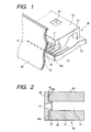
- Fig. 1 is a perspective view showing a liquid discharge head in which applicable is the producing method constituting a first embodiment of the present invention.
- Fig. 2 is a cross-sectional view along the direction of the liquid flow path of the liquid discharge head shown in Fig. 1.
- the liquid discharge head produced by the producing method of the present invention is composed, as shown in Fig. 1, a main body 46 of the head formed by adjoining a ceiling plate 60 onto a base plate 50, and an orifice plate 40 adhered to the front end face of the main body 46.
- the base plate 50 (hereinafter also called heater board) is provided with plural energy generating elements 51 (hereinafter also called heaters) for generating thermal energy to be used for discharging liquid such as ink, and Al wirings for supplying the energy generating elements 51 with electrical signals.
- the base plate 50 is obtained by forming, on an Si substrate, plural energy generating elements 51 and the Al wirings by a film forming technology.
- the ceiling plate 60 On a surface of the ceiling plate 60, there are formed grooves for constituting plural liquid paths 61 in which the energy generating elements 51 are to be respectively provided, and a groove for constituting a liquid chamber 62 for temporarily storing the ink to be supplied to the respective liquid paths 61.
- the ceiling plate 60 is further provided with a supply aperture 64 for supplying the liquid chamber 62 with ink.
- the head main body 46 provided with the plural liquid paths 61 and the plural energy generating elements 51 is obtained by adjoining the base plate 50 and the ceiling plate 60 in such a manner that the energy generating elements are respectively positioned in the plural liquid paths 61.
- the liquid paths 61 are opened on a front end face of the head main body 46, namely, as shown in Fig. 2, a face including an adjoining face 44a of the base plate 50 with the orifice plate 40 and an adjoining face 44b of the ceiling plate 60 with the orifice plate 40.
- the orifice plate 40 is provided with plural discharge openings (hereinafter also called orifices) 41 to communicate respectively with the liquid paths 61. Also around the orifices 41 in the adjoining face of the orifice plate 40 with the head main body 46, there are provided plural projections 45 which are formed independently for the respective orifices 41. In a state where the projections 45 respectively enter the liquid paths 61 and are fitted therewith, the orifice plate 40 is adhered to the adjoining faces 44a, 44b by adhesive resin 42.
- plural discharge openings hereinafter also called orifices
- the thermal energy generated from the energy generating element 51 acts on the ink in the liquid path 61, thereby generating a bubble on the energy generating element 51 and discharging ink from the orifice 41, utilizing such bubble generation.
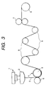
- Fig. 3 is a schematic view showing a part of the manufacturing line to be employed in the producing method for the liquid discharge head, in the first embodiment of the present invention.
- the manufacturing line shown in Fig. 3 is used for producing the orifice plate shown in Figs. 1 and 2.
- fused resin is extruded in a film, and a roller provided with relief molds of a predetermined shape is pressed onto the surface of thus extruded resinous film, thereby forming the pattern of desired shape on the surface of the resinous film.
- a die 2 of an extruder 1 extrudes the fused resin in a film shape to obtain a resinous film 3, which is then pinched between and pressed by a cooling roller 5 and a nip roller 6.
- the cooling roller 5 is surfacially provided with a relief mold 4 of a shape corresponding to the orifice 41 and the projection 45 shown in Figs. 1 and 2, and such relief mold 4 forms desired shapes in continuous manner on the surface of the resinous film 3.
- polysulfone resin (Udel P3900 supplied by Amoco Co.) as the resinous material to be extruded from the extrusion molder 1.
- the resinous material to be extruded from the extrusion molder 1, or to constitute the resinous film 3, is preferably composed of a thermoplastic polymer. More specifically, the resinous film 3 is preferably composed of any of polyethersulfone, polyphenylene sulfide and polyetherketone.
- the polysulfone resin is extruded from the die 2 with a thickness of 500 ⁇ m under the following working conditions (A), to obtain the resinous film 3.
- the resinous film 3 is cooled by pressing between the cooling roller 5 of a temperature of 15°C surfacially provided with the relief molds 4 and the nip roller 6:
- Figs. 4A, 4B, 5A and 5B are respectively a plan view and a cross-sectional view of the resinous film 3 produced by the manufacturing line shown in Fig. 3.
- Fig. 4A is a plan view of the resinous film 3
- Fig. 4B is a cross-sectional view along a line 4B-4B in Fig. 4A.
- Fig. 5A is a magnified plan view of a portion B of the resinous film shown in Fig. 4A
- Fig. 5B is a cross-sectional view along a line 5B-5B in Fig. 5A.
- an orifice 41 and a projection 45 are simultaneously formed in continuous manner and in plural units along the longitudinal direction X of the extruded resinous film 3 as shown in Figs. 4A, 4B, 5A and 5B.
- the orifices 41 and the projections 45 of a line are formed in plural units and in continuous manner along the longitudinal direction of the film, but there may also be formed plural lines parallel to the longitudinal direction.
- the pitch of the projections 45 corresponds to a resolution of 600 dpi, and the projections 45 have an external shape of a rectangular pillar.
- the projection 45 has an external dimension of 30 ⁇ 30 ⁇ m with a height of 10 ⁇ m.
- the orifice 41 has a truncated conical shape, with a diameter of 25 ⁇ m on the end face of the orifice 41 at the side of the projection 45 and a diameter of 20 ⁇ m on the end face at the opposite side.
- the relief mold 4 is so prepared that the orifice 41 and the projection 45 of the above-described shapes and dimensions are simultaneously formed in continuous manner on the resinous film 3.
- a water-repellent layer is formed on a surface (front surface) of the resinous film 3 opposite to the projections 45.
- the water-repellent treatment was conducted with CTX-CZ5A supplied by Asahi Glass Co. After the front surface is made hydrophilic by a corona treatment, the water-repellent agent is coated with a microgravure coater supplied by Yasui Seiki Co., while the resinous film 3 is unwound in the longitudinal direction.
- the step of pressing the resinous film 3 with the relief mold 4 and the step of forming the water-repellent layer on the resinous film 3 are conducted separately, but these two operations may be executed in a single step.
- the step of pressing the resinous film 3 with the relief mold 4 may be conducted while the water-repellent agent is supplied to the surface of the resinous film at the side of the nip roller, thereby forming the water-repellent layer on such surface.
- a coating roller for coating the water-repellent agent, thereby coating the resinous film 3 with the water-repellent agent.
- the orifice plate 40 After the preparation of the orifice plate 40, it is adjoined, with an adhesive material, to the head main body 46 prepared in a separate step.
- an adhesive material there is employed epoxy adhesive that can be shifted to a B-stage (hardened intermediate state) while retaining tucking property (viscous property) by ultraviolet (UV) irradiation, and, after hardening with shrinkage, can achieve adhesion of components by pressing under heating or by additional UV irradiation.
- UV ultraviolet
- the above-described epoxy adhesive is transferred, by a transfer method, onto the adjoining faces 44a, 44b of the head main body 46. Then the transferred adhesive is irradiated with ultraviolet light of 1 mW/cm 2 for 60 seconds to shift the adhesive to the B-stage state, thereby completing the hardening with shrinkage of the adhesive while retaining the tuck property.
- the projections 45 of the orifice plate 40 are respectively inserted into the corresponding liquid paths 61 whereby the projections 45 are fitted with the end portions of the liquid paths 61.
- the fitting between the projections 45 and the liquid paths 61 is executed with a gap.
- the liquid discharge head shown in Figs. 1 and 2 can be prepared through the above-described steps.
- the orifice plate can be prepared in any size, without limitation in the width of the film. Therefore, as it is unnecessary to adjoin plural orifice plates, there is not observed the defective printing resulting from the crosstalk between the neighboring nozzles induced by the peeling or defective adhesion at the adjoining portion, or the defective printing resulting from the aberration in the landing positions of the liquid droplets induced by the positional aberration between the mutually adjoined two orifice plates. Also there can be obtained an orifice plate with improved thickness distribution of the water-repellent layer.
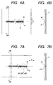
- Figs. 6A and 6B are respectively a plan view and a cross-sectional view showing another example of the resinous film prepared by the manufacturing line shown in Fig. 3.
- the row of the orifices 41 and the projections 45 is formed perpendicularly to the longitudinal direction (X) of the film as shown in Fig. 6A, in contrast to the first embodiment.
- the orifice and the projection are arranged in plural units perpendicularly to the longitudinal direction of the film, the pitch of the orifices or projections can be made free of error even in case a thin film is elongated or becomes slack in the transportation of the film or in the still state thereof.
- Figs. 7A, 7B and Figs. 8A to 8F are views showing the producing method for the liquid discharge head, in a third embodiment of the present invention.
- the method of the present embodiment is to prepare a liquid discharge head similar in configuration and shape to that of the first embodiment, and is principally different from the method of the first embodiment in that the orifice is prepared by laser working. In the following there will be principally explained the differences from the first embodiment.
- a resinous film for preparing the orifice plate is molded by the manufacturing line of the first embodiment shown in Fig. 3.
- a cooling roller 5 provided with a relief mold of another predetermined shape, instead of the relief mold 4 employed in the first embodiment.
- Fig. 7A is a plan view of the resinous film molded into a predetermined shape, by pressing with the above-described relief mold provided on the cooling roller 5, and
- Fig. 7B is a cross-sectional view along a line 7B-7B in Fig. 7A.
- Fig. 8A is a magnified plan view of a portion 8A of the resinous film shown in Fig. 7A
- Fig. 8B is a cross-sectional view along a line 8B-8B in Fig. 8A.
- a resinous film 3 is formed by extruding polysulfone resin from the die 2 with a thickness of 50 ⁇ m, with the extruding conditions (A) same as those in the first embodiment.
- the resinous film 3 is then cooled, simultaneous with pressing with the cooling roller 5 of 15°C surfacially provided with the above-mentioned relief mold and the nip roller 6.
- the relief mold provided on the cooling roller 5 independent plural projections 45 and plural recesses 47a respectively positioned at the centers of the projections 45 are formed in continuous manner along the longitudinal direction of the resinous film 3 as shown in Figs. 7A, 7B, 8A and 8B.
- the projections 45 and the recesses 47a are continuously formed in a single row along the longitudinal direction of the film, but there may be formed plural rows parallel to the longitudinal direction (X) of the film.
- Each recess 47a is to form the orifice 41.
- the pitch and the external dimension of the projections 45 are same as those in the first embodiment, and the recesses 47a have a depth of 40 ⁇ m.
- the relief mold provided on the cooling roller 5 is so prepared that such projection 45 and the recess 47a are simultaneously formed on the resinous film 3.
- the water-repellent layer is formed, by a method similar to that in the first embodiment, on a surface (front surface) of the resinous film 3 opposite to the projections 45.
- the water-repellent agent there was employed CTX-CZ5A supplied by Asahi Glass Co.
- FIGs. 8C and 8E are magnified plan views of portions 8C, 8E of the resinous film shown in Fig. 7A, while Fig. 8D is a cross-sectional view along a line 8D-8D in Fig. 8C, and Fig. 8F is a cross-sectional view along a line 8F-8F in Fig. 8E.
- each recess 47a is irradiated with a laser beam 13 to form a hole penetrating through the resinous film 3, at the bottom face of each recess 47a as shown in Figs. 8E and 8F.
- an orifice 41 with an aperture diameter of 20 ⁇ m at a side opposite to the projection 45.
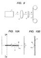
- Fig. 9 is a schematic view of a laser working apparatus for forming the orifice 41 in the resinous film 3.
- an excimer laser oscillator 9 a condenser lens 11 for condensing the laser beam 13 emitted from the excimer laser oscillator 9, and a mask 12 irradiating a predetermined portion of the resinous film 3 with the laser beam 13.
- the laser beam 13 from the oscillator 9 is guided through the condenser lens 11 and the mask 12 and irradiates the resinous film 13.
- the resinous film 3 is stored in a rolled state, and a part of the resinous film 3 is unwound and extended flat, and the laser beam 13 irradiates such flat portion of the resinous film 3.
- the manufacturing line shown in Fig. 3 and the laser working apparatus shown in Fig. 9 are formed separately, but the laser working apparatus shown in Fig. 9 may be provided in front of the winding roller 8 in the manufacturing line shown in Fig. 3.
- the irradiating portion of the laser beam 13 need not be aligned with the bottom face of the recess 47a but the entire bottom face of the recess 47a can be irradiated with the laser beam 13.
- the process for forming the orifice 41 thereby reducing the manufacturing cost of the liquid discharge head and that of the manufacturing apparatus.
- the resinous film 3 wound in a roll after the formation of the orifices 41 and the projections 45 is cut into a size of 4 inches required for each liquid discharge head, thereby obtaining the orifice plate shown in Figs. 1 and 2.
- the projections 45 of the orifice plate 40 are made to enter the liquid paths 61 of the head main body 46 and the orifice plate 40 is adjoined to the head main body 46 with the epoxy adhesive whereby obtained is the liquid discharge head explained with reference to Figs. 1 and 2.
- plural orifices obtained by forming plural recesses in the respective centers of the plural projections by extrusion molding of the film and irradiating the bottom faces of such recesses with the laser beam, are arranged along the longitudinal direction of the film, so that the orifice plate can be prepared in any size, without limitation in the width of the film. Therefore, as it is unnecessary to adjoin plural orifice plates, there is not observed the defective printing resulting from the crosstalk between the neighboring nozzles induced by the peeling or defective adhesion at the adjoining portion, or the defective printing resulting from the aberration in the landing positions of the liquid droplets induced by the positional aberration between the mutually adjoined two orifice plates. Also there can be obtained an orifice plate with improved thickness distribution of the water-repellent layer.
- Figs. 10A and 10B are views showing a method constituting a fourth embodiment of the present invention.
- the orifice is formed, as in the second embodiment, by irradiating, with the laser beam, the bottom face of the recess 47a positioned at the center of the projection 45 on the resinous film 3, but the present embodiment is different from the second embodiment in that the projections 45 and the recesses 47a are arranged in a direction perpendicular to the longitudinal direction of the film, as shown in Fig. 10A.
- the orifices obtained by forming the plural projection and the plural recesses at the respective centers of the projections by extrusion molding of the film and irradiating the bottom faces of the recesses with the laser beam, are arranged in plural units perpendicularly to the longitudinal direction of the film, so that the pitch of the orifices or projections can be made free of error even in case a thin film is elongated or becomes slack in the transportation of the film or in the still state thereof.
- polyparaphenylene terephthalamide was employed as the material of the film for preparing the orifice plate.
- Polyparaphenylene terephthalamide is featured by a low thermal expansion rate (close to the linear expansion coefficient of Si) and a high elastic modulus (ca. 1500 kg/mm 2 ).
- the orifice plate composed of polyparaphenylene terephthalamide has a linear expansion coefficient close to that of the head main body, so that the distortion, peeling or positional aberration resulting from the difference in the linear expansion does not occur when the temperature is elevated or lowered.
- the high elastic modulus provides a high rigidity, so that the front surface can be maintained flat even if the orifice plate is made thinner. A thinner orifice plate facilitates formation of the orifice with the laser.
- polyparaphenylene terephthalamide shows satisfactory ablation property with the excimer laser, and a low linear expansion coefficient. Therefore the dilatation of the orifice plate by the heat at the laser working can be made small, so that the precision of the orifice hole can be improved.
- Figs. 11A and 11B are schematic views of a manufacturing line to be employed in the present embodiment.
- PPTA is dissolved in concentrated sulfuric acid to obtain dope 901, which is degassed, filtered, and supplied and extended from a die 900 with a slit onto a tantalum belt 902 under air blowing from an air nozzle 903. It is then solidified by guiding into diluted sulfuric acid in a diluted sulfuric acid overflow tank 904. The solidified sheet is peeled off from the belt, then rinsed in a rinsing tank 905 and wound. While it is in the moist state, it is set in the unwinding position of a heating/cooling roller 910 of the apparatus shown in Fig. 11B. The roller is surfacially provided with a relief mold 907 of a predetermined shape.
- the film of polyparaphenylene terephthalamide resin is pressed by the relief mold of the heating/cooling roller 910 to obtain a resinous film of a predetermined shape, same as that shown in Figs. 7A, 7B, 8A and 8B.
- the heating/cooling roller 910 is so structured as to execute press molding in a flat portion of a caterpillar, and the pressing mold in the flat portion is so temperature controlled that the molding temperature is 350° to 380°C and the releasing temperature is 140° to 150°C.
- the feeding speed is 1 mm/sec while the pressing pressure is adjusted within a range of 12 to 13 kg/mm 2 , and the conditions are so set that the total film thickness becomes 50 ⁇ m when the molding is completed.
- the independent plural projections 45 and nplural recesses 47a are formed by the above-described relief mold in continuous manner along the longitudinal direction of the resinous film 3, as shown in Figs. 7A, 78, 8A and 8B.
- the projections 45 and the recesses 47a are continuously formed in a single row along the longitudinal direction of the film, but there may be formed plural rows parallel to the longitudinal direction of the film.
- Each recess 47a is to form the orifice 41.
- the pitch and the external dimension of the projections 45 are same as those in the first embodiment, and the recesses 47a have a depth of 40 ⁇ m.
- a relief mold 907 is provided on the heating/cooling roller 910 in such a manner that such projections 45 and the recesses 47a are simultaneously formed on the resinous film 3.
- the water-repellent layer is formed, by a method similar to that in the first embodiment, on a surface (front surface) of the resinous film 3 opposite to the projections 45.
- the water-repellent agent there was employed CTX-CZ5A supplied by Asahi Glass Co.
- the orifice plate is prepared by a process similar to that in the second embodiment.
- each recess 47a is irradiated with the laser beam 13 to form a hole penetrating through the resinous film 3, at the bottom face of each recess 47a as shown in Figs. 8E and 8F.
- the orifice 41 with an aperture diameter of 20 ⁇ m at the side opposite to the projection 45.
- the irradiating position of the laser beam 13 need not be aligned with the bottom face of the recess 47a but the entire bottom face of the recess 47a can be irradiated with the laser beam 13.
- the process for forming the orifice 41 thereby reducing the manufacturing cost of the liquid discharge head and that of the manufacturing apparatus.
- the resinous film 3 wound in a roll after the formation of the orifices 41 and the projections 45 is cut into a size of 4 inches required for each liquid discharge head, thereby obtaining the orifice plate shown in Figs. 1 and 2.
- the projections 45 of the orifice plate 40 are made to enter the liquid paths 61 of the head main body 46 and the orifice plate 40 is adjoined to the head main body 46 with the epoxy adhesive whereby obtained is the liquid discharge head explained with reference to Figs. 1 and 2.
- plural orifices obtained by forming plural recesses in the respective centers of the plural projections by extrusion molding of the film and irradiating the bottom faces of such recesses with the laser beam, are arranged along the longitudinal direction of the film, so that the orifice plate can be prepared in any size, without limitation in the width of the film. Therefore, as it is unnecessary to adjoin plural orifice plates, there is not observed the defective printing resulting from the crosstalk between the neighboring nozzles induced by the peeling or defective adhesion at the adjoining portion, or the defective printing resulting from the aberration in the landing positions of the liquid droplets induced by the positional aberration between the mutually adjoined two orifice plates. Also there can be obtained an orifice plate with improved thickness distribution of the water-repellent layer.
- the arrangement of such projections 45 and recesses 47a may be perpendicular to the longitudinal direction of the film.
- the orifices obtained by forming the plural projection and the plural recesses at the respective centers of the projections on the film and irradiating the bottom faces of the recesses with the laser beam, are arranged in plural units perpendicularly to the longitudinal direction of the film, so that the pitch of the orifices or projections can be made free of error even in case a thin film is elongated or becomes slack in the transportation of the film or in the still state thereof.
- the web-shaped resinous film 3 is continuously fed and is made to proceed along the relief mold on the roller periphery (relief mold of the cooling roller 3 shown in Fig. 3 or relief mold 907 of the heating/cooling roller 910 shown in Fig. 11B), whereby the plural projections 45 and the plural orifices 41 or recesses 47a are formed by transfer molding on the resinous film 3, which is then wound on a roller.
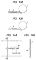
- the film overlaps in the wound state whereby the projections, the orifices and the adjoining faces around the projection for adhesion with the head main body may be damaged.
- the projection 45 is formed into a height that is equal to or lower than the surface of the resinous film 3 contacting the winding roller. Stated differently, the height of the projection 45 is made same as or lower than the depth of the recess in which the projection 45 is provided.
- FIG. 12A is a schematic perspective view of an example in which the projections 45 are arranged along the longitudinal direction of the film
- Fig. 12B is a cross-sectional view along a line 12B-12B in Fig. 12A, showing a case where the height of the projection 45 is lower than the principal surface of the film (lower than the depth of the recess 3a)
- Fig. 12C is a cross-sectional view along a line 12C-12C in Fig. 12A, showing a case where the height of the projection 45 is same as the principal surface of the film (same as the depth of the recess 3a).
- Fig. 12A is a schematic perspective view of an example in which the projections 45 are arranged along the longitudinal direction of the film
- Fig. 12B is a cross-sectional view along a line 12B-12B in Fig. 12A, showing a case where the height of the projection 45 is lower than the principal surface of the film (lower than the depth of the recess 3a)
- FIG. 13A is a schematic view showing the state of rolling the film of the present embodiment
- Fig. 13B is a schematic view showing the state of rolling a film in which the projections 45 protrude from the principal surface of the film. If the projections 45 protrude from the principal surface of the film as shown in Fig. 13B, the projections 45 may be pressed and damaged by the superposing of the film in the rolled state. However, according to the present embodiment, such drawback can be avoided since the projections 45 do not protrude from the overlapping surface of the film so that satisfactory orifice plate can be prepared.
- such contacting transport roller may be formed as a pair of rollers contacting a sheet portion outside the area bearing the projections.
- such contacting transport roller may have a contact length with the sheet, larger than the length of the recess for protecting the projection on the orifice plate, in the longitudinal direction of the film.
- such crowned roller In case of using a crowned roller (having a central portion curved outwardly) in order to avoid inclination of the web-shaped orifice plate in the course of transportation, such crowned roller is preferably so positioned as to be in contact with the surface of the sheet opposite to the surface bearing the above-mentioned projections.
- an inversely crowned roller In case of using an inversely crowned roller (having a central portion curved inwardly), it may be so positioned as to come into contact with the sheet surface bearing the projections, but preferably so as not to contact the projections in consideration of the curvature of such roller.
- Figs. 14A, 14B and Figs. 15A to 15F are views showing the method for producing the liquid discharge head of an eighth embodiment of the present invention.
- the method of the present embodiment is to prepare a liquid discharge head similar in configuration and shape to that of the first embodiment, and is principally different from the method of the first embodiment in that the orifice is prepared by laser working. Also it is different from the method of the third embodiment in that the orifice is formed by pressing with the relief mold, without forming the recess on the resinous film. In the following there will be principally explained the differences from the first and third embodiments.
- a resinous film for preparing the orifice plate is formed by the manufacturing line of the first embodiment shown in Fig. 3.
- a cooling roller 5 provided with a relief mold of another predetermined shape, instead of the relief mold 4 employed in the first embodiment.
- Fig. 14A is a plan view of the resinous film molded into a predetermined shape, by pressing polysulfone resin extruded from the die 3 of the extruder 1 with the above-described relief mold provided on the cooling roller 5, and
- Fig. 14B is a cross-sectional view along a line 14B-14B in Fig. 14A.
- Fig. 15A is a magnified plan view of a portion 15A of the resinous film shown in Fig. 14A
- Fig. 15B is a cross-sectional view along a line 15B-15B in Fig. 15A.
- a resinous film 3 is formed by extruding polysulfone resin from the die 2 with a thickness of 50 ⁇ m, with the extruding conditions (A) same as those in the first embodiment.
- the resinous film 3 is then cooled, simultaneous with pressing by the cooling roller 5 of 15°C surfacially provided with the above-mentioned relief mold and the nip roller 6.
- independent plural projections 48a for forming the projections 45 are formed in continuous manner along the extruding direction of the resinous film 3 as shown in Figs. 14A, 14B, 15A and 15B.
- the pitch and the external dimension of the projections 48a are same as those of the projections 45 to be finally formed on the resinous film 3.
- the relief mold provided on the cooling roller 5 is so prepared that such projection 48a are formed on the resinous film 3.
- the water-repellent layer is formed, by a method similar to that in the first embodiment, on a surface (front surface) of the resinous film 3 opposite to the projections 48a.
- the water-repellent agent there was employed CTX-CZ5A supplied by Asahi Glass Co.
- FIGs. 15C and 15E are magnified plan views of portions 15C, 15E of the resinous film shown in Fig. 14A, while Fig. 15D is a cross-sectional view along a line 15D-15D in Fig. 15C, and Fig. 15F is a cross-sectional view along a line 15F-15F in Fig. 15E.
- each projection 48a is irradiated with a laser beam 13 to form a hole penetrating through the resinous film 3, namely the orifice 41, at the center of each projection 48a as shown in Figs. 15E and 15F.
- a hole penetrating through the resinous film 3 namely the orifice 41, at the center of each projection 48a as shown in Figs. 15E and 15F.
- an orifice 41 with an aperture diameter of 20 ⁇ m at a side opposite to the projection 45.
- the orifice 41 is formed in the resinous film 3 by a method similar to that in the third embodiment, with the laser working apparatus of the second embodiment shown in Fig. 9.
- the resinous film 3 wound in a roll after the formation of the orifices 41 and the projections 45 is cut into a size of 4 inches required for each liquid discharge head, thereby obtaining the orifice plate shown in Figs. 1 and 2.
- the projections 45 of the orifice plate 40 are made to enter the liquid paths 61 of the head main body 46 and the orifice plate 40 is adjoined to the head main body 46 with the epoxy adhesive whereby obtained is the liquid discharge head explained with reference to Figs. 1 and 2.
- each orifice plate 40 is not prepared in divided manner but in an integral structure, so that even the orifice plate 40 with a large number of orifices 41 can be obtained without any joint therein and with satisfactory dimensional precision of the orifices 41 and the projections 45.
- the recording with thus prepared liquid discharge head was free from defects such as deviation of the flying liquid droplets or non-uniformity in the recorded image, resulting from the defects in the joint in the orifice plate, encountered when the orifice plate is prepared in divided manner and provided satisfactory recording quality.
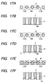
- Figs. 16A, 16B and Figs. 17A to 17F are views showing the method for producing the liquid discharge head of a nineth embodiment of the present invention.
- the method of the present embodiment is to prepare a liquid discharge head similar in configuration and shape to that of the first embodiment, and is principally different from the method of the first embodiment in that the projection around the orifice is prepared by laser working. In the following there will be principally explained the differences from the first embodiment.
- a resinous film for preparing the orifice plate is formed by the manufacturing line of the first embodiment shown in Fig. 3.
- a cooling roller 5 provided with a relief mold of another predetermined shape, instead of the relief mold 4 employed in the first embodiment.
- Fig. 16A is a plan view of the resinous film molded into a predetermined shape, by pressing polysulfone resin extruded from the die 2 of the extruder 1 with the above-described relief mold provided on the cooling roller 5, and
- Fig. 16B is a cross-sectional view along a line 16B-16B in Fig. 16A.
- Fig. 17A is a magnified plan view of a portion 17A of the resinous film shown in Fig. 16A, and Fig. 17B is a cross-sectional view along a line 17B-17B in Fig. 17A.
- a resinous film 3 is formed by extruding polysulfone resin from the die 2 with a thickness of 50 ⁇ m, with the extruding conditions (A) same as those in the first embodiment.
- the resinous film 3 is then cooled, simultaneous with pressing by the cooling roller 5 of 15°C surfacially provided with the above-mentioned relief mold and the nip roller 6.
- a projection 48b continuous in the extruding direction of the film for forming the projections 45 and plural orifices 41 arranged in the projection 48b are formed on the resinous film 3 as shown in Figs. 16A, 16B, 17A and 17B.
- the projection 48b has a width of 30 ⁇ m and a height of 10 ⁇ m.
- the relief mold provided on the cooling roller 5 is so prepared that such projection 48b and orifices 41 are formed on the resinous film 3.
- the water-repellent layer is formed, by a method similar to that in the first embodiment, on a surface (front surface) of the resinous film 3 opposite to the projections 48a.
- the water-repellent agent there was employed CTX-CZ5A supplied by Asahi Glass Co.
- FIGs. 17C and 17E are magnified plan views of portions 17C, 17E of the resinous film shown in Fig. 16A, while Fig. 17D is a cross-sectional view along a line 17D-17D in Fig. 17C, and Fig. 17F is a cross-sectional view along a line 17F-17F in Fig. 17E.
- the unnecessary portions of the projection 48b are eliminated by irradiating the portions excluding the portions corresponding to the orifices 41 and the projections 45 on the end face of the projection 48b with the laser beam 13, thereby forming independent plural projections 45 respectively corresponding to the orifices 41.
- the projections 45 are formed with the laser working apparatus of the third embodiment shown in Fig. 9, but the mask 12 in the third embodiment is replaced by another mask with a predetermined pattern for forming the projections 45.
- the resinous film 3 wound in a roll after the formation of the orifices 41 and the projections 45 is cut into a size of 4 inches required for each liquid discharge head, thereby obtaining the orifice plate shown in Figs. 1 and 2.
- the projections 45 of the orifice plate 40 are made to enter the liquid paths 61 of the head main body 46 and the orifice plate 40 is adjoined to the head main body 46 with the epoxy adhesive whereby obtained is the liquid discharge head explained with reference to Figs. 1 and 2.
- each orifice plate 40 is not prepared in divided manner but in an integral structure, so that even the orifice plate 40 with a large number of orifices 41 can be obtained without any joint therein and with satisfactory dimensional precision of the orifices 41 and the projections 45.
- the recording with thus prepared liquid discharge head was free from defects such as deviation of the flying liquid droplets or non-uniformity in the recorded image, resulting from the defects in the joint in the orifice plate, encountered when the orifice plate is prepared in divided manner and provided satisfactory recording quality.
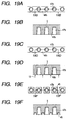
- Figs. 18A, 18B, Fig. 19A to 19F and Figs. 20A to 20D are views showing the method for producing the liquid discharge head of a tenth embodiment of the present invention.
- the method of the present embodiment is to prepare a liquid discharge head similar in configuration and shape to that of the first embodiment.
- a resinous film for preparing the orifice plate is formed by the manufacturing line of the first embodiment shown in Fig. 3.
- a cooling roller 5 provided with a relief mold of another predetermined shape, instead of the relief mold 4 employed in the first embodiment.
- a cooling roller 5 provided with a relief mold of another predetermined shape instead of the relief mold 4 employed in the first embodiment.
- Fig. 18A is a plan view of the resinous film molded into a predetermined shape, by pressing polysulfone resin extruded from the die 2 of the extruder 1 with the above-described relief mold provided on the cooling roller 5, and
- Fig. 18B is a cross-sectional view along a line 18B-18B in Fig. 18A.
- Fig. 19A is a magnified plan view of a portion 19A of the resinous film shown in Fig. 18A
- Fig. 19B is a cross-sectional view along a line 19B-19B in Fig. 19A.
- a resinous film 3 is formed by extruding polysulfone resin from the die 2 with a thickness of 50 ⁇ m, with the extruding conditions (A) same as those in the first embodiment.
- the resinous film 3 is then cooled, simultaneous with pressing by the cooling roller 5 of 15°C surfacially provided with the above-mentioned relief mold and the nip roller 6.
- the relief mold provided on the cooling roller 5 a projection 48b continuous in the extruding direction of the film for forming the projections 45 and plural recesses 47b arranged in the projection 48b are formed on the resinous film 3 as shown in Figs. 18A, 18B, 19A and 19B.
- Each recess 47a is form the orifice 41, and the plural recesses 47b are mutually independent.
- the projection 48b has a width of 30 ⁇ m and a height of 10 ⁇ m.
- the relief mold provided on the cooling roller 5 is so prepared that such projection 48b and recesses 47b are formed on the resinous film 3.
- the water-repellent layer is formed, by a method similar to that in the first embodiment, on a surface (front surface) of the resinous film 3 opposite to the projection 48b.
- the water-repellent agent there was employed CTX-CZ5A supplied by Asahi Glass Co.
- FIGs. 19C, 19E, 20A and 20C are magnified plan views of a portion 20A of the resinous film shown in Fig. 18A, while Fig. 19D is a cross-sectional view along a line 19D-19D in Fig. 19C, Fig. 19F is a cross-sectional view along a line 19F-19F in Fig. 19E, Fig. 20B is a cross-sectional view along a line 20B-20B in Fig. 20A, and Fig. 20D is a cross-sectional view along a line 20D-20D in Fig. 20C.
- the unnecessary portions of the projection 48b are eliminated by irradiating the portions excluding the portions corresponding to the recesses 47b and the projections 45 on the end face of the projection 48b with the laser beam 13, thereby forming independent plural projections 45 respectively corresponding to the recesses 47b.
- each recess 47b is irradiated with the laser beam 13 to form a hole penetrating through the resinous film 3 as shown in Figs. 20C and 20D, whereby an orifice 41 with an aperture diameter of 20 ⁇ m at a side opposite to the projection 45 is formed on the resinous film 3.
- the orifices 41 and the projections 45 are formed in the resinous film 3 with the laser working apparatus of the third embodiment shown in Fig. 9.
- the mask 12 in the third embodiment is replaced by another mask with a predetermined pattern for forming the projections 45 as in the nineth embodiment, and, in forming the orifices 41, a mask 12 similar to that in the third embodiment is employed for opening the bottom face of the recess 47b.
- the irradiating position of the laser beam 13 need not be aligned with the bottom face of the recess 47b but the entire bottom face of the recess 47a can be irradiated with the laser beam 13.
- the process for forming the orifice 41 thereby reducing the manufacturing cost of the liquid discharge head and that of the manufacturing apparatus.
- the resinous film 3 wound in a roll after the formation of the orifices 41 and the projections 45 is cut into a size of 4 inches required for each liquid discharge head, thereby obtaining the orifice plate shown in Figs. 1 and 2.
- the projections 45 of the orifice plate 40 are made to enter the liquid paths 61 of the head main body 46 and the orifice plate 40 is adjoined to the head main body 46 with the epoxy adhesive whereby obtained is the liquid discharge head explained with reference to Figs. 1 and 2.
- each orifice plate 40 is not prepared in divided manner but in an integral structure, so that even the orifice plate 40 with a large number of orifices 41 can be obtained without any joint therein and with satisfactory dimensional precision of the orifices 41 and the projections 45.
- the recording with thus prepared liquid discharge head was free from defects such as deviation of the flying liquid droplets or non-uniformity in the recorded image, resulting from the defects in the joint in the orifice plate, encountered when the orifice plate is prepared in divided manner and provided satisfactory recording quality.
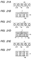
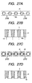
- Figs. 21A to 21F and Figs. 22A to 22D are views showing the method for producing the liquid discharge head of an eleventh embodiment of the present invention.
- the method of the present embodiment is to prepare a liquid discharge head similar in configuration and shape to that of the first embodiment.
- the step for forming the orifices by laser working and the step for forming the projections by laser working are exchanged in order, in comparison with the method of the tenth embodiment.
- a resinous film 3 with the projection 48b and the recesses 47b as in the tenth embodiment is formed by the manufacturing line of the first embodiment shown in Fig. 3.
- the water-repellent layer is formed, by a method similar to that in the first embodiment, on a surface (front surface) of the resinous film 3 opposite to the projection 48b.
- the water-repellent agent there was employed CTX-CZ5A supplied by Asahi Glass Co.
- FIGS. 21A, 21C, 21E, 22A and 22C are magnified plan views of portions 22A, 22C of the resinous film shown in Fig. 18A, while Fig. 21B is a cross-sectional view along a line 21B-21B in Fig. 21A, Fig. 21D is a cross-sectional view along a line 21D-21D in Fig. 21C, Fig. 21F is a cross-sectional view along a line 21F-21F in Fig. 21E, Fig. 22B is a cross-sectional view along a line 22B-22B in Fig. 22A and Fig. 22D is a cross-sectional view along a line 22D-22D in Fig. 22C.
- the resinous film 3 is provided with the projection 48b and the recesses 47b explained in the tenth embodiment, by pressing with the relief mold provided on the cooling roller 5.
- each recess 47b is irradiated with the laser beam 13 to form a hole penetrating through the resinous film 3 as shown in Figs. 21E and 21F, whereby an orifice 41 with an aperture diameter of 20 ⁇ m at a side opposite to the projection 45 is formed on the resinous film 3.
- the unnecessary portions of the projection 48b are eliminated by irradiating the portions excluding the portions corresponding to the orifices 41 and the projections 45 on the end face of the projection 48b with the laser beam 13, thereby forming independent plural projections 45 respectively corresponding to the orifices 41 as shown in Figs. 22C and 22D.
- the projections 45 and the orifices 41 are formed with the laser working apparatus of the third embodiment shown in Fig. 9.
- the irradiating position of the laser beam 13 need not be aligned with the bottom face of the recess 47b but the entire bottoms face of the recess 47a can be irradiated with the laser beam 13.
- the process for forming the orifice 41 thereby reducing the manufacturing cost of the liquid discharge head and that of the manufacturing apparatus.
- the resinous film 3 wound in a roll after the formation of the orifices 41 and the projections 45 is cut into a size of 4 inches required for each liquid discharge head, thereby obtaining the orifice plate shown in Figs. 1 and 2.
- the projections 45 of the orifice plate 40 are made to enter the liquid paths 61 of the head main body 46 and the orifice plate 40 is adjoined to the head main body 46 with the epoxy adhesive whereby obtained is the liquid discharge head explained with reference to Figs. 1 and 2.
- each orifice plate 40 is not prepared in divided manner but in an integral structure, so that even the orifice plate 40 with a large number of orifices 41 can be obtained without any joint therein and with satisfactory dimensional precision of the orifices 41 and the projections 45.
- the recording with thus prepared liquid discharge head was free from defects such as deviation of the flying liquid droplets or non-uniformity in the recorded image, resulting from the defects in the joint in the orifice plate, encountered when the orifice plate is prepared in divided manner and provided satisfactory recording quality.
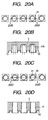
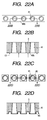
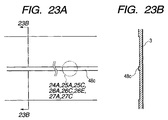
- Figs. 23A, 23B, Figs. 24A to 24F and Fig. 25A to 25D are views showing the method for producing the liquid discharge head of a twelfth embodiment of the present invention.
- the method of the present embodiment is to prepare a liquid discharge head similar in configuration and shape to that of the first embodiment.
- a resinous film for preparing the orifice plate is formed by the manufacturing line of the first embodiment shown in Fig. 3.
- a cooling roller 5 provided with a relief mold of another predetermined shape, instead of the relief mold 4 employed in the first embodiment.
- Fig. 23A is a plan view of the resinous film molded into a predetermined shape, by pressing polysulfone resin extruded from the die 2 of the extruder 1 with the above-described relief mold provided on the cooling roller 5, and
- Fig. 23B is a cross-sectional view along a line 23B-23B in Fig. 23A.
- Fig. 24A is a magnified plan view of a portion 24A of the resinous film shown in Fig. 23A, and Fig. 24B is a cross-sectional view along a line 24B-24B in Fig. 24A.
- a resinous film 3 is formed by extruding polysulfone resin from the die 2 with a thickness of 50 ⁇ m, with the extruding conditions (A) same as those in the first embodiment.
- the resinous film 3 is then cooled, simultaneous with pressing by the cooling roller 5 of 15°C surfacially provided with the above-mentioned relief mold and the nip roller 6.
- a projection 48c continuous in the extruding direction of the film for forming the plural projections 45 as shown in Figs. 1 and 2 is formed on the resinous film 3 as shown in Figs. 23A, 23B, 24A and 24B.
- the projection 48b is to form the projections 45 has a width of 30 ⁇ m and a height of 10 ⁇ m.
- the relief mold provided on the cooling roller 5 is so prepared that such projection 48c is formed on the resinous film 3.
- the water-repellent layer is formed, by a method similar to that in the first embodiment, on a surface (front surface) of the resinous film 3 opposite to the projections 48a.
- the water-repellent agent there was employed CTX-CZ5A supplied by Asahi Glass Co.
- FIGs. 24C, 24E, 25A and 25C are magnified plan views of portions 25A, 25C of the resinous film shown in Fig. 23A, while Fig. 24D is a cross-sectional view along a line 24D-24D in Fig. 24C, Fig. 24F is a cross-sectional view along a line 24F-24F in Fig. 24E, Fig. 25B is a cross-sectional view along a line 25B-25B in Fig. 25A and Fig. 25D is a cross-sectional view along a line 25D-25D in Fig. 25C.
- each projection 48d is similar in external shape to the projection 45, and has a dimension of 30 ⁇ 30 ⁇ m and a height of 10 ⁇ m.
- each projection 48d is irradiated with the laser beam 13 to form a hole penetrating through the resinous film 3 in the center of each projection 48d as shown in Figs. 25C and 25D, whereby an orifice 41 with an aperture diameter of 25 ⁇ m at the side of the projection 45 and an aperture diameter of 20 ⁇ m at a side opposite to the projection 45 is formed on the resinous film 3.
- the projections 48d, the projections 45 and the orifices 41 are formed with the laser working apparatus of the third embodiment shown in Fig. 9.
- the mask 12 in the second embodiment is replaced by another mask with a predetermined pattern for forming the projections 45 as in the nineth embodiment, and, in forming the orifices 41, a mask 12 similar to that in the second embodiment is employed for opening the central part of the projection 48d.
- the resinous film 3 wound in a roll after the formation of the orifices 41 and the projections 45 is cut into a size of 4 inches required for each liquid discharge head, thereby obtaining the orifice plate shown in Figs. 1 and 2.
- the projections 45 of the orifice plate 40 are made to enter the liquid paths 61 of the head main body 46 and the orifice plate 40 is adjoined to the head main body 46 with the epoxy adhesive whereby obtained is the liquid discharge head explained with reference to Figs. 1 and 2.
- each orifice plate 40 is not prepared in divided manner but in an integral structure, so that even the orifice plate 40 with a large number of orifices 41 can be obtained without any joint therein and with satisfactory dimensional precision of the orifices 41 and the projections 45.
- the recording with thus prepared liquid discharge head was free from defects such as deviation of the flying liquid droplets or non-uniformity in the recorded image, resulting from the defects in the joint in the orifice plate, encountered when the orifice plate is prepared in divided manner and provided satisfactory recording quality.
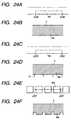
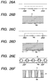
- Figs. 26A to 26F and Figs. 27A to 27D are views showing the method for producing the liquid discharge head of a thirteenth embodiment of the present invention.
- the method of the present embodiment is to prepare a liquid discharge head similar in configuration and shape to that of the first embodiment.
- the producing method of the present embodiment is different from that of the twelfth embodiment in that the orifice is formed prior to the formation of the external shape of the projection to be fitted in the liquid path.
- a resinous film 3 bearing the projection 48c of the twelfth embodiment shown in Figs. 24A to 24F is formed by the manufacturing line of the first embodiment shown in Fig. 3.
- the water-repellent layer is formed, by a method similar to that in the first embodiment, on a surface (front surface) of the resinous film 3 opposite to the projections 48c.
- the water-repellent agent there was employed CTX-CZ5A supplied by Asahi Glass Co.
- FIGS. 26A, 26C, 26E, 27A and 27C are magnified plan views of portions 26A, 26C, 26E, 27A and 27C of the resinous film shown in Fig. 23A, while Fig. 26B is a cross-sectional view along a line 26B-26B in Fig. 26A, Fig. 26D is a cross-sectional view along a line 26D-26D in Fig. 26C, Fig.
- 26F is a cross-sectional view along a line 26F-26F in Fig. 26E
- Fig. 27B is a cross-sectional view along a line 27B-27B in Fig. 27A
- Fig. 27D is a cross-sectional view along a line 27D-27D in Fig. 27C.
- the resinous film 3 is provided with the projection 48c explained in the twelfth embodiment, by the pressing with the relief mold provided on the cooling roller 5.
- the portion, corresponding to the orifice 41 shown in Figs. 1 and 2, of the end face of the projection 48c is irradiated with the laser beam 13 to form a hole penetrating through the resinous film 3 in the projection 48c as shown in Figs. 26E and 26F, whereby an orifice 41 with an aperture diameter of 25 ⁇ m at the side of the projection 45 and an aperture diameter of 20 ⁇ m at a side opposite to the projection 45 is formed on the resinous film 3.
- the unnecessary portions of the projection 48c are eliminated by irradiating the portions excluding the portions corresponding to the orifices 41 and the projections 45 on the end face of the projection 48c with the laser beam 13, thereby forming independent plural projections 45 respectively corresponding to the orifices 41 as shown in Figs. 27C and 27D.
- the projections 45 and the orifices 41 are formed with the laser working apparatus of the third embodiment shown in Fig. 9.
- the resinous film 3 sound in a roll after the formation of the orifices 41 and the projections 45 is cut into a size of 4 inches required for each liquid discharge head, thereby obtaining the orifice plate shown in Figs. 1 and 2.
- the projections 45 of the orifice plate 40 are made to enter the liquid paths 61 of the head main body 46 and the orifice plate 40 is adjoined to the head main body 46 with the epoxy adhesive whereby obtained is the liquid discharge head explained with reference to Figs. 1 and 2.
- each orifice plate 40 is not prepared in divided manner but in an integral structure, so that even the orifice plate 40 with a large number of orifices 41 can be obtained without any joint therein and with satisfactory dimensional precision of the orifices 41 and the projections 45.
- the recording with thus prepared liquid discharge head was free from defects such as deviation of the flying liquid droplets or non-uniformity in the recorded image, resulting from the defects in the joint in the orifice plate, encountered when the orifice plate is prepared in divided manner and provided satisfactory recording quality.
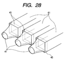
- Fig. 28 is an exploded perspective view of the liquid discharge head in which the present invention is applied. In the present embodiment, portions similar to those in the foregoing first embodiment will not be explained further.
- the aperture of the orifice 41 at the side of the projection 45 is rectangular, similar to the cross sectional shape of the liquid path, and, is circular or oval at the side discharging liquid droplet.
- the orifice has a curved shape smoothly narrowing from the side of the head main body in the liquid droplet discharging direction, and such shape can improve the discharge efficiency.
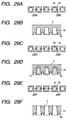
- Figs. 29A to 29F are views showing the method for producing the projection and the orifice of the present embodiment on the resinous film by the manufacturing line shown in Fig. 3 and the laser working apparatus shown in Fig. 9.
- independent plural projections 45 and plural recesses 43 are formed on the resinous film 3 in continuous manner in the extruding direction thereof, by the relief mold 4 provided on the cooling roller 5.
- Each recess 43 is used for forming the orifice 41.
- the bottom face of each recess 43 is irradiated with the laser beam 13 to form a hole penetrating through the resinous film 3 in the bottom face of each recess 43, as shown in Figs. 29E and 29F.
- the thickness of the bottom of the recess 43 should be as small as possible, preferably not exceeding 20 ⁇ m, more preferably not exceeding 10 ⁇ m and most preferably not exceeding 5 ⁇ m. When the thickness does not exceed 5 ⁇ m, the entire bottom face of the recess can be irradiated without executing alignment.
- the laser irradiation for forming the penetrating hole may be made in a portion corresponding to the orifice, from the back surface of the resinous film opposite to the surface bearing the projection 45.
- the thickness of the bottom-face of the recess is preferably 5 ⁇ m or less, more preferably 3 ⁇ m or less.
- Cation-polymerizable epoxy adhesive that can be shifted to a B-stage while retaining tucking property by UV irradiation, and, after hardening with shrinkage, can achieve adhesion of components by pressing under heating, is transferred by a transfer method onto the adjoining faces 44a, 44b of the head main body, having the apertures of the liquid paths 61. Then the transferred adhesive is irradiated with ultraviolet light of 1 mW/cm 2 for 60 seconds to shift the adhesive to the B-stage state, thereby completing the hardening with shrinkage.
- the projections 45 of the orifice plate 40 are respectively inserted into the corresponding liquid paths 61 of the head main body 46 having the liquid paths 61, base plate 50 and ceiling plate 60.
- the present embodiment employs, for adhering the orifice plate and the head main body, epoxy adhesive that can be shifted to the B-stage to complete hardening with shrinkage by UV irradiation while maintaining the tucking property, and that can be hardened by additional UV irradiation or heating.
- This adhesive can also be adhered by pressing under heating only.
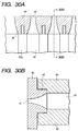
- Figs. 30A and 30B are respectively a plan view and a cross-sectional view along a line 30B-30B in Fig. 30A, showing the configuration of orifices of the orifice plate in an embodiment of the present invention.
- projection 45 of the orifice plate 40 fitted in the liquid paths 61, has a structure coming in close contact with the liquid path wall 61, base plate 50 and ceiling plate 60 in a plane perpendicular to the ink flow.
- the projection 45 may be in contact in at least two faces of the liquid path wall 60a, base plate 50 and ceiling plate 60.
- the contact face of the projection 45 of the orifice plate 40 is so structured as not to protrude toward the ink liquid path. Such structure enables smooth ink flow and prevents formation of bubble trapping.
- the orifice plate 40 is provided with a recess and a projection 45 in the adjoining face with the head main body 46, and the projection 45 has a shape matching the cross-sectional shape of the liquid path 61 and is provided with the orifice 41, and the projection 45 or a part thereof is inserted into and is fitted with the liquid path 61 of the head main body 46.
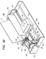
- Fig. 32 is a perspective view showing an ink jet recording apparatus, constituting an example of the liquid discharge recording apparatus, employing the liquid discharge head prepared with the above-described orifice plate.
- the head cartridge 601 is mounted on a carriage 607, engaging with a spiral groove 606 of a lead screw 606, rotating through transmission gears 603, 604 in the forward or reverse direction by a driving motor 602.
- the power of the driving motor 602 reciprocates the head cartridge 601 together with the carriage 607 in directions a and b along a guide member 608.
- the ink jet recording apparatus 600 is provided with recording medium transport means (not shown) for transporting a recording medium, such as a print sheet P, for receiving the liquid such as ink discharged from the head cartridge 601.
- a pressure plate 610 presses the print sheet P, transported on a platen 609 by the recording medium transport means, toward the platen 609 over the moving range of the carriage 607.
- photocouplers 611, 612 which constitute home position detecting means for detecting the presence of a lever 607a of the carriage 607 in the area of the photocouplers 611, 612 and switching the rotating direction of the driving motor 602.
- a support member 613 for supporting a cap member 614 which covers the front face, having the orifices, of the head cartridge 601.
- ink suction means 615 for sucking the ink idly discharged from the head cartridge 601 and accumulated in the interior of the cap member 614.
- the ink suction means 615 executes suction recovery of the head cartridge 601 through the aperture of the cap member 614.
- the ink jet recording apparatus 600 is also provided with a main body support member 619, which supports a movable member 618 in movable manner in the front-back direction, namely in a direction perpendicular to the moving direction of the carriage 607.
- a cleaning blade 617 is mounted on the movable member 618.
- the cleaning blade 617 is not limited to the illustrated form but may assume other known forms.
- An ink jet recording control unit for supplying the heat generating members provided in the head cartridge 601 with driving signals and controlling the functions of the above-described mechanisms is provided in the main body of the ink jet recording apparatus and is not shown in Fig. 32.
- the ink jet recording control unit is provided with a drive signal supply means for supplying the drive signals for causing the liquid discharge head to discharge liquid.
- the ink jet recording apparatus 600 of the above-described configuration executes recording on the print sheet P, transported on the platen 609 by the aforementioned recording medium transport means, by the reciprocating motion of the head cartridge P over the entire width of the print sheet P.
- a method for producing a liquid discharge head provided with a head main body including plural energy generating elements for generating energy for discharging liquid as a flying liquid droplet, and plural liquid paths in which the energy generating elements are respectively provided and an orifice plate provided with plural discharge ports respectively communicating with the liquid paths and plural independent projections formed around the discharge ports and respectively corresponding to the discharge ports so as to enter into the liquid paths and to engage therewith, and adjoined to the head main body, the method comprising the steps of forming plural projections and the discharge ports while a continuous resinous film is transported, separating the film in continuous manner in a predetermined size including the portion where the discharge ports are formed, thereby preparing the orifice plate and a step of adjoining the orifice plate to the head main body.
Abstract
Description
- The present invention relates to a method for producing liquid discharge head for discharging liquid as a flying liquid droplet to deposit it on a recording medium thereby forming a record, a liquid discharge head produced by such method, a head cartridge and a liquid discharge recording apparatus including such liquid discharge head.
- The present invention is applicable to an apparatus such as a printer for recording on a recording medium such as paper, yarn, fiber, fabrics, leather, metal, plastics, glass, timber, ceramics etc., a copying apparatus, a facsimile apparatus having communicating function, or a word processor having a printer unit, or an industrial recording apparatus combined in complex manner with various processing apparatus.
- In the present invention, "recording" means not only providing the recording medium with a meaningful image such as a character or graphics but also providing with a meaningless image such as a pattern. Related Background Art
- The ink jet recording apparatus, effecting recording by discharging recording liquid (ink) from the orifice of the liquid discharge head, is already known to be excellent in low noise and high speed recording.
- Such ink jet recording apparatus has been proposed in various systems, some of which are already commercialized and some are still under development for commercialization.
- With the recent progress in the recording technology, there is being required recording of a higher speed and a higher definition, and the size of the discharge opening (orifice diameter) is becoming smaller with an arrangement of the orifices of a higher density. For this reason, there is being commonly employed an orifice forming method of employing a resinous film such as of polysulfone, polyethersulfone, polyphenylene sulfide or polyetherketone as the orifice plate and forming the orifice by fine working by excimer laser ablation on such resinous film.
- However, it is extremely difficult to adjoin the orifice plate having a small orifice, without a gap, to the corresponding liquid path to be communicated with the orifice.
- Consequently, there is adopted a method, as shown in Figs. 15A to 15F, of forming a
projection 245 in the vicinity of anorifice 241 on anorifice plate 240 at the side thereof at amain body 246 of the head and fittingsuch projection 245 or a part thereof into a flow path orliquid path 261. This method can prevent the intrusion of the adhesive resin into theorifice 241 or theliquid path 261. The formation of theprojection 245 on theorifice plate 240 is executed by working with an excimer laser as in the formation of the discharge opening 241. - As explained in the foregoing, with the recent process in the recording technology, there is being required recording with a higher speed and a higher precision, and the number of nozzles is increasing in order to increasing the printing speed.
- Therefore, there has been encountered a drawback that the orifice or the projection is not formed in the predetermined position.
- In consideration of the foregoing, an object of the present invention is to provide a method for producing the liquid discharge head, capable of easily forming the orifice or the projection at the predetermined position with a high production yield, even in an orifice plate with a large number of nozzles.
- Another object of the present invention is to provide a method for producing the liquid discharge head by adjoining an orifice plate having an orifice to a head main body having a liquid path by forming a projection around the orifice of the orifice plate and inserting such projection into the liquid path of the head main body, the method being free from defects such as an error in the pitch of the orifices or a defective shape of the orifice or a failure in the entry of the projection into the liquid path.
- The present inventors have found that, by forming plural orifices and plural projections in continuous manner in the course of continuous transportation of a resinous film, the positioning for each orifice plate can be dispensed with, and the orifices and the projections can be formed in the predetermined positions since the continuous film is subjected to a tension during transportation.
- The present inventors have also found that, in continuous formation of the plural orifices and the plural projections on the resinous film, the performance of the recording head is affected by the relationship between the direction of arrangement of the plural orifices and the plural projections on the resinous film and the longitudinal direction of the film.
- Also in case of winding the film into a roll after the formation of the orifices and the projections, such projections, orifices or an adjoining face, to be adjoined to the head main body, around the projection may be crushed or damaged by overlapping of the film in the wound state, and such drawbacks have to be prevented for producing the satisfactory head.
- According to the present invention, such drawbacks can be prevented by a method for producing a liquid discharge head provided with:
- a head main body including plural energy generating elements for generating energy for discharging liquid as a flying liquid droplet, and plural liquid paths in which the energy generating elements are respectively provided; and
- an orifice plate provided with plural discharge ports respectively communicating with the liquid paths and plural independent projections formed around the discharge ports and respectively corresponding to the discharge ports so as to enter into the liquid paths and to engage therewith, and adjoined to the head main body, the method comprising:
- a step of forming plural projections and the discharge ports while a continuous resinous film is transported;
- a step of separating the film in continuous manner in a predetermined size including the portion where the discharge ports are formed, thereby preparing the orifice plate; and
- a step of adjoining the orifice plate to the head main body.
-
-
- Fig. 1 is a perspective view showing a liquid discharge head in which applicable is the producing method constituting a first embodiment of the present invention for producing the liquid discharge head;
- Fig. 2 is a cross-sectional view along the direction of the liquid path of the liquid discharge head shown in Fig. 1;
- Fig. 3 is a schematic view showing a part of the manufacturing line to be used in the producing method for the liquid discharge head constituting the first embodiment of the present invention;
- Figs. 4A and 4B are respectively a plan view and a cross-sectional view of a resinous film prepared by the manufacturing line shown in Fig. 3;
- Figs. 5A and 5B are respectively a plan view and a cross-sectional view of a resinous film prepared by the manufacturing line shown in Fig. 3;
- Figs. 6A and 6B are views showing the producing method for the liquid discharge head, constituting a second embodiment of the present invention;
- Figs. 7A and 7B are views showing the producing method for the liquid discharge head, constituting a third embodiment of the present invention;
- Figs. 8A, 8B, 8C, 8D, 8E and 8F are views showing the producing method for the liquid discharge head, in the third embodiment of the present invention;
- Fig. 9 is a schematic view of a laser working apparatus for forming the orifice in the resinous film;
- Figs. 10A and 10B are views showing the producing method for the liquid discharge head, constituting a fourth embodiment of the present invention;
- Figs. 11A and 11B are schematic views showing an apparatus applied to the producing method for the liquid discharge head, in a fifth embodiment of the present invention;
- Figs. 12A, 12B and 12C are views showing the configuration of a sheet-shaped orifice plate to be employed in the producing method for the liquid discharge head of the present invention;
- Figs. 13A and 13B are views showing the effect of a seventh embodiment of the present invention;
- Figs. 14A and 14B are views showing the producing method for the liquid discharge head, in an eighth embodiment of the present invention;
- Figs. 15A, 15B, 15C, 15D, 15E and 15F are views showing the producing method for the liquid discharge head, in the eighth embodiment of the present invention;
- Figs. 16A and 16B and Figs. 17A, 17B, 17C, 17D, 17E and 17F are views showing the producing method for the liquid discharge head, in a nineth embodiment of the present invention;
- Figs. 18A and 18B, Figs. 19A, 19B, 19C, 19D, 19E and 19F and Figs. 20A, 20B, 20C and 20D are views showing the producing method for the liquid discharge head, in a tenth embodiment of the present invention;
- Figs. 21A, 21B, 21C, 21D, 21E and 21F and Figs. 22A, 22B, 22C and 22D are views showing the producing method for the liquid discharge head, in an eleventh embodiment of the present invention;
- Figs. 23A, 23B and Figs. 24A, 24B, 24C, 24D, 24E and 24F are views showing the producing method for the liquid discharge head, in a twelfth embodiment of the present invention;
- Figs. 25A, 25B, 25C and 25D and Figs. 26A, 26B, 26C, 26D, 26E and 26F are views showing the producing method for the liquid discharge head, in a thirteenth embodiment of the present invention;
- Figs. 27A, 27B, 27C, and 27D are views showing the producing method for the liquid discharge head, in a fourteenth embodiment of the present invention;
- Fig. 28 is a perspective view of a portion of the orifice and the liquid path in the liquid discharge head in the fourteenth embodiment of the present invention;
- Figs. 29A, 29B, 29C, 29D, 29E and 29F are views showing the producing method for the projection and the orifice on the resinous film prepared by the manufacturing line shown in Fig. 3 and by the laser working apparatus shown in Fig. 9;
- Figs. 30A and 30B are respectively a plan view and
a cross-sectional view, along a
line 30B-30B in the plan view, showing the configuration of the orifice or the orifice plate in the fourth embodiment of the present invention; - Fig. 31 is a view showing a state in which the adjoining face of the projection of the orifice plate protrudes toward the ink flow path;
- Fig. 32 is a perspective view showing an example of the liquid discharge recording apparatus loaded with the liquid discharge head employing the orifice plate prepared by the method of the present invention; and
- Fig. 33 is a perspective view showing the liquid discharge head provided in the conventional ink jet recording apparatus.
-
- Now the present invention will be clarified in detail by preferred embodiments thereof, with reference to the attached drawings.
- Fig. 1 is a perspective view showing a liquid discharge head in which applicable is the producing method constituting a first embodiment of the present invention. Fig. 2 is a cross-sectional view along the direction of the liquid flow path of the liquid discharge head shown in Fig. 1.
- The liquid discharge head produced by the producing method of the present invention is composed, as shown in Fig. 1, a
main body 46 of the head formed by adjoining aceiling plate 60 onto abase plate 50, and anorifice plate 40 adhered to the front end face of themain body 46. The base plate 50 (hereinafter also called heater board) is provided with plural energy generating elements 51 (hereinafter also called heaters) for generating thermal energy to be used for discharging liquid such as ink, and Al wirings for supplying theenergy generating elements 51 with electrical signals. Thebase plate 50 is obtained by forming, on an Si substrate, pluralenergy generating elements 51 and the Al wirings by a film forming technology. - On a surface of the
ceiling plate 60, there are formed grooves for constituting pluralliquid paths 61 in which theenergy generating elements 51 are to be respectively provided, and a groove for constituting aliquid chamber 62 for temporarily storing the ink to be supplied to the respectiveliquid paths 61. Theceiling plate 60 is further provided with asupply aperture 64 for supplying theliquid chamber 62 with ink. The headmain body 46 provided with theplural liquid paths 61 and the pluralenergy generating elements 51 is obtained by adjoining thebase plate 50 and theceiling plate 60 in such a manner that the energy generating elements are respectively positioned in theplural liquid paths 61. Theliquid paths 61 are opened on a front end face of the headmain body 46, namely, as shown in Fig. 2, a face including anadjoining face 44a of thebase plate 50 with theorifice plate 40 and an adjoining face 44b of theceiling plate 60 with theorifice plate 40. - On the other hand, the
orifice plate 40 is provided with plural discharge openings (hereinafter also called orifices) 41 to communicate respectively with theliquid paths 61. Also around theorifices 41 in the adjoining face of theorifice plate 40 with the headmain body 46, there are providedplural projections 45 which are formed independently for therespective orifices 41. In a state where theprojections 45 respectively enter theliquid paths 61 and are fitted therewith, theorifice plate 40 is adhered to the adjoiningfaces 44a, 44b byadhesive resin 42. - In this liquid discharge head, the thermal energy generated from the
energy generating element 51 acts on the ink in theliquid path 61, thereby generating a bubble on theenergy generating element 51 and discharging ink from theorifice 41, utilizing such bubble generation. - Fig. 3 is a schematic view showing a part of the manufacturing line to be employed in the producing method for the liquid discharge head, in the first embodiment of the present invention. The manufacturing line shown in Fig. 3 is used for producing the orifice plate shown in Figs. 1 and 2. In this manufacturing line, fused resin is extruded in a film, and a roller provided with relief molds of a predetermined shape is pressed onto the surface of thus extruded resinous film, thereby forming the pattern of desired shape on the surface of the resinous film.
- As shown in Fig. 3, a
die 2 of an extruder 1 extrudes the fused resin in a film shape to obtain aresinous film 3, which is then pinched between and pressed by a coolingroller 5 and anip roller 6. The coolingroller 5 is surfacially provided with a relief mold 4 of a shape corresponding to theorifice 41 and theprojection 45 shown in Figs. 1 and 2, and such relief mold 4 forms desired shapes in continuous manner on the surface of theresinous film 3. - The
resinous film 3, subjected to surfacial formation of the desired shape by the relief mold 4 and cooled by the coolingroller 5, passes certain rollers and two drawing rollers 7 and wound into a roll by a windingroller 8, in such a manner that theprojections 45 are directed toward the outside of the windingroller 8. - In the producing method for the liquid discharge head of the present embodiment, there was employed polysulfone resin (Udel P3900 supplied by Amoco Co.) as the resinous material to be extruded from the extrusion molder 1. The resinous material to be extruded from the extrusion molder 1, or to constitute the
resinous film 3, is preferably composed of a thermoplastic polymer. More specifically, theresinous film 3 is preferably composed of any of polyethersulfone, polyphenylene sulfide and polyetherketone. - In the following there will be explained the method for preparing the
orifice plate 40. - At first, the polysulfone resin is extruded from the
die 2 with a thickness of 500 µm under the following working conditions (A), to obtain theresinous film 3. Theresinous film 3 is cooled by pressing between the coolingroller 5 of a temperature of 15°C surfacially provided with the relief molds 4 and the nip roller 6: -
- die aperture 0.5 mm;
- extruder set temperature 315°C at the rear part, 360°C at the intermediate part and 370°C in the head and die;
- cooling roller temperature 15°C;
-
extrusion thickness 50 µm; - nip pressure (air gauge pressure) 2 kgf/cm2.
-
- Figs. 4A, 4B, 5A and 5B are respectively a plan view and a cross-sectional view of the
resinous film 3 produced by the manufacturing line shown in Fig. 3. Fig. 4A is a plan view of theresinous film 3, and Fig. 4B is a cross-sectional view along aline 4B-4B in Fig. 4A. Also Fig. 5A is a magnified plan view of a portion B of the resinous film shown in Fig. 4A, and Fig. 5B is a cross-sectional view along aline 5B-5B in Fig. 5A. By pressing the surface of theresinous film 3 with the relief mold 4 of the coolingroller 5, anorifice 41 and aprojection 45 are simultaneously formed in continuous manner and in plural units along the longitudinal direction X of the extrudedresinous film 3 as shown in Figs. 4A, 4B, 5A and 5B. In the present embodiment, theorifices 41 and theprojections 45 of a line are formed in plural units and in continuous manner along the longitudinal direction of the film, but there may also be formed plural lines parallel to the longitudinal direction. - The pitch of the
projections 45 corresponds to a resolution of 600 dpi, and theprojections 45 have an external shape of a rectangular pillar. Theprojection 45 has an external dimension of 30 × 30 µm with a height of 10 µm. Theorifice 41 has a truncated conical shape, with a diameter of 25 µm on the end face of theorifice 41 at the side of theprojection 45 and a diameter of 20 µm on the end face at the opposite side. The relief mold 4 is so prepared that theorifice 41 and theprojection 45 of the above-described shapes and dimensions are simultaneously formed in continuous manner on theresinous film 3. - After the formation of the
orifices 41 and theprojections 45 by the relief mold 4 on theresinous film 3, a water-repellent layer is formed on a surface (front surface) of theresinous film 3 opposite to theprojections 45. The water-repellent treatment was conducted with CTX-CZ5A supplied by Asahi Glass Co. After the front surface is made hydrophilic by a corona treatment, the water-repellent agent is coated with a microgravure coater supplied by Yasui Seiki Co., while theresinous film 3 is unwound in the longitudinal direction. There were conducted in succession a step of coating the water-repellent agent so as to obtain a water-repellent layer of a final thickness of 0.1 µm, and a step of prebaking the coated water-repellent agent at 80°C. Theresinous film 3 wound in a roll after such coating and prebaking steps is heated at 150°C for 5 hours in an oven to complete the water-repellent layer on the front face of theresinous film 3. - In the producing method of the present embodiment for the liquid discharge head, the step of pressing the
resinous film 3 with the relief mold 4 and the step of forming the water-repellent layer on theresinous film 3 are conducted separately, but these two operations may be executed in a single step. For example, the step of pressing theresinous film 3 with the relief mold 4 may be conducted while the water-repellent agent is supplied to the surface of the resinous film at the side of the nip roller, thereby forming the water-repellent layer on such surface. Otherwise, in a position before the winding of theresinous film 3 by the windingroller 8, there can be provided a coating roller for coating the water-repellent agent, thereby coating theresinous film 3 with the water-repellent agent. - The
resinous film 3, subjected to the formation of theorifices 41 and theprojections 45 and wound in a roll, is cut into a size required for each liquid discharge head, whereby theorifice plate 40 shown in Figs. 1 and 2 can be prepared. - In the following there will be explained the producing method for the liquid discharge head after the preparation of the
orifice plate 40. - After the preparation of the
orifice plate 40, it is adjoined, with an adhesive material, to the headmain body 46 prepared in a separate step. There is employed epoxy adhesive that can be shifted to a B-stage (hardened intermediate state) while retaining tucking property (viscous property) by ultraviolet (UV) irradiation, and, after hardening with shrinkage, can achieve adhesion of components by pressing under heating or by additional UV irradiation. Also there is known such adhesive that can achieve adhesion by pressing under heating only, without passing through the B-stage state. - At first the above-described epoxy adhesive is transferred, by a transfer method, onto the adjoining
faces 44a, 44b of the headmain body 46. Then the transferred adhesive is irradiated with ultraviolet light of 1 mW/cm2 for 60 seconds to shift the adhesive to the B-stage state, thereby completing the hardening with shrinkage of the adhesive while retaining the tuck property. - Then the
projections 45 of theorifice plate 40 are respectively inserted into the correspondingliquid paths 61 whereby theprojections 45 are fitted with the end portions of theliquid paths 61. The fitting between theprojections 45 and theliquid paths 61 is executed with a gap. - Then a load of 1 kg/cm2 is applied to the
orifice plate 40 on the surface thereof opposite to theprojections 45, thereby maintaining theorifice plate 40 and the headmain body 46 in close contact, and, while such state is maintained, the headmain body 46 is pressed to theorifice plate 40 under heating at 60° C thereby completing the hardening of the adhesive. - The liquid discharge head shown in Figs. 1 and 2 can be prepared through the above-described steps. In the producing method of the present embodiment for the liquid discharge head, since plural orifice and plural projections are arranged along the longitudinal direction of the film, the orifice plate can be prepared in any size, without limitation in the width of the film. Therefore, as it is unnecessary to adjoin plural orifice plates, there is not observed the defective printing resulting from the crosstalk between the neighboring nozzles induced by the peeling or defective adhesion at the adjoining portion, or the defective printing resulting from the aberration in the landing positions of the liquid droplets induced by the positional aberration between the mutually adjoined two orifice plates. Also there can be obtained an orifice plate with improved thickness distribution of the water-repellent layer.
- Figs. 6A and 6B are respectively a plan view and a cross-sectional view showing another example of the resinous film prepared by the manufacturing line shown in Fig. 3.
- In the present embodiment, in forming the
orifice 41 and theprojection 45 by extrusion molding of theresinous film 3, the row of theorifices 41 and theprojections 45 is formed perpendicularly to the longitudinal direction (X) of the film as shown in Fig. 6A, in contrast to the first embodiment. - According to the method of the present embodiment, since the orifice and the projection are arranged in plural units perpendicularly to the longitudinal direction of the film, the pitch of the orifices or projections can be made free of error even in case a thin film is elongated or becomes slack in the transportation of the film or in the still state thereof.
- Figs. 7A, 7B and Figs. 8A to 8F are views showing the producing method for the liquid discharge head, in a third embodiment of the present invention. The method of the present embodiment is to prepare a liquid discharge head similar in configuration and shape to that of the first embodiment, and is principally different from the method of the first embodiment in that the orifice is prepared by laser working. In the following there will be principally explained the differences from the first embodiment.
- Also in the producing method of the present embodiment, a resinous film for preparing the orifice plate is molded by the manufacturing line of the first embodiment shown in Fig. 3. There is however employed a
cooling roller 5 provided with a relief mold of another predetermined shape, instead of the relief mold 4 employed in the first embodiment. Fig. 7A is a plan view of the resinous film molded into a predetermined shape, by pressing with the above-described relief mold provided on thecooling roller 5, and Fig. 7B is a cross-sectional view along aline 7B-7B in Fig. 7A. Fig. 8A is a magnified plan view of aportion 8A of the resinous film shown in Fig. 7A, and Fig. 8B is a cross-sectional view along aline 8B-8B in Fig. 8A. - At first a
resinous film 3 is formed by extruding polysulfone resin from thedie 2 with a thickness of 50 µm, with the extruding conditions (A) same as those in the first embodiment. Theresinous film 3 is then cooled, simultaneous with pressing with the coolingroller 5 of 15°C surfacially provided with the above-mentioned relief mold and thenip roller 6. Thus, by the relief mold provided on thecooling roller 5, independentplural projections 45 andplural recesses 47a respectively positioned at the centers of theprojections 45 are formed in continuous manner along the longitudinal direction of theresinous film 3 as shown in Figs. 7A, 7B, 8A and 8B. In the present embodiment, theprojections 45 and therecesses 47a are continuously formed in a single row along the longitudinal direction of the film, but there may be formed plural rows parallel to the longitudinal direction (X) of the film. Eachrecess 47a is to form theorifice 41. The pitch and the external dimension of theprojections 45 are same as those in the first embodiment, and therecesses 47a have a depth of 40 µm. The relief mold provided on thecooling roller 5 is so prepared thatsuch projection 45 and therecess 47a are simultaneously formed on theresinous film 3. - Then the water-repellent layer is formed, by a method similar to that in the first embodiment, on a surface (front surface) of the
resinous film 3 opposite to theprojections 45. As the water-repellent agent, there was employed CTX-CZ5A supplied by Asahi Glass Co. - In the following there will be explained, with reference to Figs. 8A to 8F, the process for preparing the orifice plate after the formation of the water-repellent layer on the
resinous film 3. Figs. 8C and 8E are magnified plan views ofportions line 8D-8D in Fig. 8C, and Fig. 8F is a cross-sectional view along aline 8F-8F in Fig. 8E. - As shown in Fig. 8D, the bottom face of each
recess 47a is irradiated with alaser beam 13 to form a hole penetrating through theresinous film 3, at the bottom face of eachrecess 47a as shown in Figs. 8E and 8F. Thus there is formed, in theresinous film 3, anorifice 41 with an aperture diameter of 20 µm at a side opposite to theprojection 45. - Fig. 9 is a schematic view of a laser working apparatus for forming the
orifice 41 in theresinous film 3. In the laser working apparatus shown in Fig. 9, there are provided an excimer laser oscillator 9, acondenser lens 11 for condensing thelaser beam 13 emitted from the excimer laser oscillator 9, and amask 12 irradiating a predetermined portion of theresinous film 3 with thelaser beam 13. Thelaser beam 13 from the oscillator 9 is guided through thecondenser lens 11 and themask 12 and irradiates theresinous film 13. Theresinous film 3 is stored in a rolled state, and a part of theresinous film 3 is unwound and extended flat, and thelaser beam 13 irradiates such flat portion of theresinous film 3. - In the present embodiment, the manufacturing line shown in Fig. 3 and the laser working apparatus shown in Fig. 9 are formed separately, but the laser working apparatus shown in Fig. 9 may be provided in front of the winding
roller 8 in the manufacturing line shown in Fig. 3. - In case the depth of the
recess 47a is made large with respect to the thickness of theresinous film 3 thereby reducing the film thickness for opening theorifice 41 by thelaser beam 13 to a required dimensional tolerance, the irradiating portion of thelaser beam 13 need not be aligned with the bottom face of therecess 47a but the entire bottom face of therecess 47a can be irradiated with thelaser beam 13. Thus there can be simplified the process for forming theorifice 41, thereby reducing the manufacturing cost of the liquid discharge head and that of the manufacturing apparatus. - Then, the
resinous film 3 wound in a roll after the formation of theorifices 41 and theprojections 45 is cut into a size of 4 inches required for each liquid discharge head, thereby obtaining the orifice plate shown in Figs. 1 and 2. - Then, as explained in the first embodiment, the
projections 45 of theorifice plate 40 are made to enter theliquid paths 61 of the headmain body 46 and theorifice plate 40 is adjoined to the headmain body 46 with the epoxy adhesive whereby obtained is the liquid discharge head explained with reference to Figs. 1 and 2. - According to the method of the present embodiment, plural orifices, obtained by forming plural recesses in the respective centers of the plural projections by extrusion molding of the film and irradiating the bottom faces of such recesses with the laser beam, are arranged along the longitudinal direction of the film, so that the orifice plate can be prepared in any size, without limitation in the width of the film. Therefore, as it is unnecessary to adjoin plural orifice plates, there is not observed the defective printing resulting from the crosstalk between the neighboring nozzles induced by the peeling or defective adhesion at the adjoining portion, or the defective printing resulting from the aberration in the landing positions of the liquid droplets induced by the positional aberration between the mutually adjoined two orifice plates. Also there can be obtained an orifice plate with improved thickness distribution of the water-repellent layer.
- Figs. 10A and 10B are views showing a method constituting a fourth embodiment of the present invention.
- In the present embodiment, the orifice is formed, as in the second embodiment, by irradiating, with the laser beam, the bottom face of the
recess 47a positioned at the center of theprojection 45 on theresinous film 3, but the present embodiment is different from the second embodiment in that theprojections 45 and therecesses 47a are arranged in a direction perpendicular to the longitudinal direction of the film, as shown in Fig. 10A. - According to the method of the present embodiment, the orifices, obtained by forming the plural projection and the plural recesses at the respective centers of the projections by extrusion molding of the film and irradiating the bottom faces of the recesses with the laser beam, are arranged in plural units perpendicularly to the longitudinal direction of the film, so that the pitch of the orifices or projections can be made free of error even in case a thin film is elongated or becomes slack in the transportation of the film or in the still state thereof.
- In the present embodiment, polyparaphenylene terephthalamide was employed as the material of the film for preparing the orifice plate.
- Polyparaphenylene terephthalamide (PPTA) is featured by a low thermal expansion rate (close to the linear expansion coefficient of Si) and a high elastic modulus (ca. 1500 kg/mm2). As the energy generating elements of the head main body are provided on an Si substrate, the orifice plate composed of polyparaphenylene terephthalamide has a linear expansion coefficient close to that of the head main body, so that the distortion, peeling or positional aberration resulting from the difference in the linear expansion does not occur when the temperature is elevated or lowered. Also the high elastic modulus provides a high rigidity, so that the front surface can be maintained flat even if the orifice plate is made thinner. A thinner orifice plate facilitates formation of the orifice with the laser. Also polyparaphenylene terephthalamide shows satisfactory ablation property with the excimer laser, and a low linear expansion coefficient. Therefore the dilatation of the orifice plate by the heat at the laser working can be made small, so that the precision of the orifice hole can be improved.
- In the following there will be explained the preparation of an orifice plate composed of PPTA, with reference to Figs. 7A, 7B, 8A, 8B, 9 and Figs. 11A and 11B. Figs. 11A and 11B are schematic views of a manufacturing line to be employed in the present embodiment.
- In the apparatus shown in Fig. 11A, PPTA is dissolved in concentrated sulfuric acid to obtain
dope 901, which is degassed, filtered, and supplied and extended from adie 900 with a slit onto atantalum belt 902 under air blowing from anair nozzle 903. It is then solidified by guiding into diluted sulfuric acid in a diluted sulfuricacid overflow tank 904. The solidified sheet is peeled off from the belt, then rinsed in arinsing tank 905 and wound. While it is in the moist state, it is set in the unwinding position of a heating/cooling roller 910 of the apparatus shown in Fig. 11B. The roller is surfacially provided with arelief mold 907 of a predetermined shape. The film of polyparaphenylene terephthalamide resin is pressed by the relief mold of the heating/cooling roller 910 to obtain a resinous film of a predetermined shape, same as that shown in Figs. 7A, 7B, 8A and 8B. - The heating/
cooling roller 910 is so structured as to execute press molding in a flat portion of a caterpillar, and the pressing mold in the flat portion is so temperature controlled that the molding temperature is 350° to 380°C and the releasing temperature is 140° to 150°C. The feeding speed is 1 mm/sec while the pressing pressure is adjusted within a range of 12 to 13 kg/mm2, and the conditions are so set that the total film thickness becomes 50 µm when the molding is completed. - Thus the independent
plural projections 45 andnplural recesses 47a, respectively positioned at the centers of theprojections 45, are formed by the above-described relief mold in continuous manner along the longitudinal direction of theresinous film 3, as shown in Figs. 7A, 78, 8A and 8B. In the present embodiment, theprojections 45 and therecesses 47a are continuously formed in a single row along the longitudinal direction of the film, but there may be formed plural rows parallel to the longitudinal direction of the film. Eachrecess 47a is to form theorifice 41. The pitch and the external dimension of theprojections 45 are same as those in the first embodiment, and therecesses 47a have a depth of 40 µm. Arelief mold 907 is provided on the heating/cooling roller 910 in such a manner thatsuch projections 45 and therecesses 47a are simultaneously formed on theresinous film 3. - Then the water-repellent layer is formed, by a method similar to that in the first embodiment, on a surface (front surface) of the
resinous film 3 opposite to theprojections 45. As the water-repellent agent, there was employed CTX-CZ5A supplied by Asahi Glass Co. - After the preparation of the water-repellent layer on the
resinous film 3, the orifice plate is prepared by a process similar to that in the second embodiment. - More specifically, as shown in Fig. 8D, the bottom face of each
recess 47a is irradiated with thelaser beam 13 to form a hole penetrating through theresinous film 3, at the bottom face of eachrecess 47a as shown in Figs. 8E and 8F. Thus there is formed, in theresinous film 3, theorifice 41 with an aperture diameter of 20 µm at the side opposite to theprojection 45. - In case the depth of the
recess 47a is made large with respect to the thickness of theresinous film 3 thereby reducing the film thickness for opening theorifice 41 by thelaser beam 13 to a required dimensional tolerance, the irradiating position of thelaser beam 13 need not be aligned with the bottom face of therecess 47a but the entire bottom face of therecess 47a can be irradiated with thelaser beam 13. Thus there can be simplified the process for forming theorifice 41, thereby reducing the manufacturing cost of the liquid discharge head and that of the manufacturing apparatus. - Then, the
resinous film 3 wound in a roll after the formation of theorifices 41 and theprojections 45 is cut into a size of 4 inches required for each liquid discharge head, thereby obtaining the orifice plate shown in Figs. 1 and 2. - Then, as explained in the first embodiment, the
projections 45 of theorifice plate 40 are made to enter theliquid paths 61 of the headmain body 46 and theorifice plate 40 is adjoined to the headmain body 46 with the epoxy adhesive whereby obtained is the liquid discharge head explained with reference to Figs. 1 and 2. - According to the method of the present embodiment, plural orifices, obtained by forming plural recesses in the respective centers of the plural projections by extrusion molding of the film and irradiating the bottom faces of such recesses with the laser beam, are arranged along the longitudinal direction of the film, so that the orifice plate can be prepared in any size, without limitation in the width of the film. Therefore, as it is unnecessary to adjoin plural orifice plates, there is not observed the defective printing resulting from the crosstalk between the neighboring nozzles induced by the peeling or defective adhesion at the adjoining portion, or the defective printing resulting from the aberration in the landing positions of the liquid droplets induced by the positional aberration between the mutually adjoined two orifice plates. Also there can be obtained an orifice plate with improved thickness distribution of the water-repellent layer.
- In forming the
plural projections 45 and therecesses 47a respectively positioned at the centers of theprojections 45 in the foregoing fifth embodiment on theresinous film 3 composed of polyparaphenylene terephthalamide, the arrangement ofsuch projections 45 andrecesses 47a may be perpendicular to the longitudinal direction of the film. - According to the method of the present embodiment, the orifices, obtained by forming the plural projection and the plural recesses at the respective centers of the projections on the film and irradiating the bottom faces of the recesses with the laser beam, are arranged in plural units perpendicularly to the longitudinal direction of the film, so that the pitch of the orifices or projections can be made free of error even in case a thin film is elongated or becomes slack in the transportation of the film or in the still state thereof.
- In the foregoing embodiments, the web-shaped
resinous film 3 is continuously fed and is made to proceed along the relief mold on the roller periphery (relief mold of the coolingroller 3 shown in Fig. 3 orrelief mold 907 of the heating/cooling roller 910 shown in Fig. 11B), whereby theplural projections 45 and theplural orifices 41 orrecesses 47a are formed by transfer molding on theresinous film 3, which is then wound on a roller. - In such case, the film overlaps in the wound state whereby the projections, the orifices and the adjoining faces around the projection for adhesion with the head main body may be damaged.
- In consideration of such situation, it is preferable to form a recess on a surface of the
resinous film 3 and to form theprojection 45 on the bottom face of such recess, as shown in Figs. 4B, 6B, 7B and 10B. In such case, theprojection 45 is formed into a height that is equal to or lower than the surface of theresinous film 3 contacting the winding roller. Stated differently, the height of theprojection 45 is made same as or lower than the depth of the recess in which theprojection 45 is provided. - An example of such configuration is shown in Figs. 12A to 12C. Fig. 12A is a schematic perspective view of an example in which the
projections 45 are arranged along the longitudinal direction of the film, while Fig. 12B is a cross-sectional view along aline 12B-12B in Fig. 12A, showing a case where the height of theprojection 45 is lower than the principal surface of the film (lower than the depth of therecess 3a), and Fig. 12C is a cross-sectional view along aline 12C-12C in Fig. 12A, showing a case where the height of theprojection 45 is same as the principal surface of the film (same as the depth of therecess 3a). Also Fig. 13A is a schematic view showing the state of rolling the film of the present embodiment, and Fig. 13B is a schematic view showing the state of rolling a film in which theprojections 45 protrude from the principal surface of the film. If theprojections 45 protrude from the principal surface of the film as shown in Fig. 13B, theprojections 45 may be pressed and damaged by the superposing of the film in the rolled state. However, according to the present embodiment, such drawback can be avoided since theprojections 45 do not protrude from the overlapping surface of the film so that satisfactory orifice plate can be prepared. - Also in the above-described method, even in an orifice plate lacking the
projection 45 around theorifice 41, the orifice and the forming face therefor can be protected since no contact is caused in the rolling operation around the orifice hole which is essential for the discharge characteristics. - In the sheet transporting system as shown in Fig. 3, it is preferable to pay consideration to the configuration of the transporting rollers coming into contact with the projection-bearing surface of the sheet (for example the transporting rollers a, b in Fig. 3), in such a manner that the projections of the orifice plate are not abraded by or do not engage with the periphery of such transporting roller. For this purpose, such contacting transport roller may be formed as a pair of rollers contacting a sheet portion outside the area bearing the projections.
- Otherwise, such contacting transport roller may have a contact length with the sheet, larger than the length of the recess for protecting the projection on the orifice plate, in the longitudinal direction of the film.
- In case of using a crowned roller (having a central portion curved outwardly) in order to avoid inclination of the web-shaped orifice plate in the course of transportation, such crowned roller is preferably so positioned as to be in contact with the surface of the sheet opposite to the surface bearing the above-mentioned projections. On the other hand, in case of using an inversely crowned roller (having a central portion curved inwardly), it may be so positioned as to come into contact with the sheet surface bearing the projections, but preferably so as not to contact the projections in consideration of the curvature of such roller.
- Figs. 14A, 14B and Figs. 15A to 15F are views showing the method for producing the liquid discharge head of an eighth embodiment of the present invention. The method of the present embodiment is to prepare a liquid discharge head similar in configuration and shape to that of the first embodiment, and is principally different from the method of the first embodiment in that the orifice is prepared by laser working. Also it is different from the method of the third embodiment in that the orifice is formed by pressing with the relief mold, without forming the recess on the resinous film. In the following there will be principally explained the differences from the first and third embodiments.
- Also in the producing method of the present embodiment, a resinous film for preparing the orifice plate is formed by the manufacturing line of the first embodiment shown in Fig. 3. There is however employed a
cooling roller 5 provided with a relief mold of another predetermined shape, instead of the relief mold 4 employed in the first embodiment. Fig. 14A is a plan view of the resinous film molded into a predetermined shape, by pressing polysulfone resin extruded from thedie 3 of the extruder 1 with the above-described relief mold provided on thecooling roller 5, and Fig. 14B is a cross-sectional view along aline 14B-14B in Fig. 14A. Fig. 15A is a magnified plan view of aportion 15A of the resinous film shown in Fig. 14A, and Fig. 15B is a cross-sectional view along aline 15B-15B in Fig. 15A. - At first a
resinous film 3 is formed by extruding polysulfone resin from thedie 2 with a thickness of 50 µm, with the extruding conditions (A) same as those in the first embodiment. Theresinous film 3 is then cooled, simultaneous with pressing by the coolingroller 5 of 15°C surfacially provided with the above-mentioned relief mold and thenip roller 6. Thus, by the relief mold provided on thecooling roller 5, independentplural projections 48a for forming theprojections 45 are formed in continuous manner along the extruding direction of theresinous film 3 as shown in Figs. 14A, 14B, 15A and 15B. The pitch and the external dimension of theprojections 48a are same as those of theprojections 45 to be finally formed on theresinous film 3. The relief mold provided on thecooling roller 5 is so prepared thatsuch projection 48a are formed on theresinous film 3. - Then the water-repellent layer is formed, by a method similar to that in the first embodiment, on a surface (front surface) of the
resinous film 3 opposite to theprojections 48a. As the water-repellent agent, there was employed CTX-CZ5A supplied by Asahi Glass Co. - In the following there will be explained, with reference to Figs. 15A to 15F, the process for preparing the orifice plate after the formation of the water-repellent layer on the
resinous film 3. Figs. 15C and 15E are magnified plan views ofportions line 15D-15D in Fig. 15C, and Fig. 15F is a cross-sectional view along aline 15F-15F in Fig. 15E. - As shown in Fig. 15D, the central portion of the end face each
projection 48a is irradiated with alaser beam 13 to form a hole penetrating through theresinous film 3, namely theorifice 41, at the center of eachprojection 48a as shown in Figs. 15E and 15F. Thus there is formed, in theresinous film 3, anorifice 41 with an aperture diameter of 20 µm at a side opposite to theprojection 45. Theorifice 41 is formed in theresinous film 3 by a method similar to that in the third embodiment, with the laser working apparatus of the second embodiment shown in Fig. 9. - Then, the
resinous film 3 wound in a roll after the formation of theorifices 41 and theprojections 45 is cut into a size of 4 inches required for each liquid discharge head, thereby obtaining the orifice plate shown in Figs. 1 and 2. - Then, as explained in the first embodiment, the
projections 45 of theorifice plate 40 are made to enter theliquid paths 61 of the headmain body 46 and theorifice plate 40 is adjoined to the headmain body 46 with the epoxy adhesive whereby obtained is the liquid discharge head explained with reference to Figs. 1 and 2. - According to the method of the present embodiment, as in the first embodiment, each
orifice plate 40 is not prepared in divided manner but in an integral structure, so that even theorifice plate 40 with a large number oforifices 41 can be obtained without any joint therein and with satisfactory dimensional precision of theorifices 41 and theprojections 45. Thus there can be avoided the defect that theprojections 45 of theorifice plate 40 cannot be fitted with theliquid paths 61 of the headmain body 46. Also the recording with thus prepared liquid discharge head was free from defects such as deviation of the flying liquid droplets or non-uniformity in the recorded image, resulting from the defects in the joint in the orifice plate, encountered when the orifice plate is prepared in divided manner and provided satisfactory recording quality. - Figs. 16A, 16B and Figs. 17A to 17F are views showing the method for producing the liquid discharge head of a nineth embodiment of the present invention. The method of the present embodiment is to prepare a liquid discharge head similar in configuration and shape to that of the first embodiment, and is principally different from the method of the first embodiment in that the projection around the orifice is prepared by laser working. In the following there will be principally explained the differences from the first embodiment.
- Also in the producing method of the present embodiment, a resinous film for preparing the orifice plate is formed by the manufacturing line of the first embodiment shown in Fig. 3. There is however employed a
cooling roller 5 provided with a relief mold of another predetermined shape, instead of the relief mold 4 employed in the first embodiment. Fig. 16A is a plan view of the resinous film molded into a predetermined shape, by pressing polysulfone resin extruded from thedie 2 of the extruder 1 with the above-described relief mold provided on thecooling roller 5, and Fig. 16B is a cross-sectional view along aline 16B-16B in Fig. 16A. Fig. 17A is a magnified plan view of aportion 17A of the resinous film shown in Fig. 16A, and Fig. 17B is a cross-sectional view along aline 17B-17B in Fig. 17A. - At first a
resinous film 3 is formed by extruding polysulfone resin from thedie 2 with a thickness of 50 µm, with the extruding conditions (A) same as those in the first embodiment. Theresinous film 3 is then cooled, simultaneous with pressing by the coolingroller 5 of 15°C surfacially provided with the above-mentioned relief mold and thenip roller 6. Thus, by the relief mold provided on thecooling roller 5, aprojection 48b continuous in the extruding direction of the film for forming theprojections 45 andplural orifices 41 arranged in theprojection 48b are formed on theresinous film 3 as shown in Figs. 16A, 16B, 17A and 17B. Theprojection 48b has a width of 30 µm and a height of 10 µm. The relief mold provided on thecooling roller 5 is so prepared thatsuch projection 48b andorifices 41 are formed on theresinous film 3. - Then the water-repellent layer is formed, by a method similar to that in the first embodiment, on a surface (front surface) of the
resinous film 3 opposite to theprojections 48a. As the water-repellent agent, there was employed CTX-CZ5A supplied by Asahi Glass Co. - In the following there will be explained, with reference to Figs. 17A to 17F, the process for preparing the orifice plate after the formation of the water-repellent layer on the
resinous film 3. Figs. 17C and 17E are magnified plan views ofportions line 17D-17D in Fig. 17C, and Fig. 17F is a cross-sectional view along aline 17F-17F in Fig. 17E. - As shown in Fig. 17D, the unnecessary portions of the
projection 48b are eliminated by irradiating the portions excluding the portions corresponding to theorifices 41 and theprojections 45 on the end face of theprojection 48b with thelaser beam 13, thereby forming independentplural projections 45 respectively corresponding to theorifices 41. Theprojections 45 are formed with the laser working apparatus of the third embodiment shown in Fig. 9, but themask 12 in the third embodiment is replaced by another mask with a predetermined pattern for forming theprojections 45. - Then, the
resinous film 3 wound in a roll after the formation of theorifices 41 and theprojections 45 is cut into a size of 4 inches required for each liquid discharge head, thereby obtaining the orifice plate shown in Figs. 1 and 2. - Then, as explained in the first embodiment, the
projections 45 of theorifice plate 40 are made to enter theliquid paths 61 of the headmain body 46 and theorifice plate 40 is adjoined to the headmain body 46 with the epoxy adhesive whereby obtained is the liquid discharge head explained with reference to Figs. 1 and 2. - According to the method of the present embodiment, as in the first embodiment, each
orifice plate 40 is not prepared in divided manner but in an integral structure, so that even theorifice plate 40 with a large number oforifices 41 can be obtained without any joint therein and with satisfactory dimensional precision of theorifices 41 and theprojections 45. Thus there can be avoided the defect that theprojections 45 of theorifice plate 40 cannot be fitted with theliquid paths 61 of the headmain body 46. Also the recording with thus prepared liquid discharge head was free from defects such as deviation of the flying liquid droplets or non-uniformity in the recorded image, resulting from the defects in the joint in the orifice plate, encountered when the orifice plate is prepared in divided manner and provided satisfactory recording quality. - Figs. 18A, 18B, Fig. 19A to 19F and Figs. 20A to 20D are views showing the method for producing the liquid discharge head of a tenth embodiment of the present invention. The method of the present embodiment is to prepare a liquid discharge head similar in configuration and shape to that of the first embodiment.
- Also in the producing method of the present embodiment, a resinous film for preparing the orifice plate is formed by the manufacturing line of the first embodiment shown in Fig. 3. There is however employed a
cooling roller 5 provided with a relief mold of another predetermined shape, instead of the relief mold 4 employed in the first embodiment. There is however employed acooling roller 5 provided with a relief mold of another predetermined shape, instead of the relief mold 4 employed in the first embodiment. Fig. 18A is a plan view of the resinous film molded into a predetermined shape, by pressing polysulfone resin extruded from thedie 2 of the extruder 1 with the above-described relief mold provided on thecooling roller 5, and Fig. 18B is a cross-sectional view along aline 18B-18B in Fig. 18A. Fig. 19A is a magnified plan view of aportion 19A of the resinous film shown in Fig. 18A, and Fig. 19B is a cross-sectional view along aline 19B-19B in Fig. 19A. - At first a
resinous film 3 is formed by extruding polysulfone resin from thedie 2 with a thickness of 50 µm, with the extruding conditions (A) same as those in the first embodiment. Theresinous film 3 is then cooled, simultaneous with pressing by the coolingroller 5 of 15°C surfacially provided with the above-mentioned relief mold and thenip roller 6. Thus, by the relief mold provided on thecooling roller 5, aprojection 48b continuous in the extruding direction of the film for forming theprojections 45 andplural recesses 47b arranged in theprojection 48b are formed on theresinous film 3 as shown in Figs. 18A, 18B, 19A and 19B. Eachrecess 47a is form theorifice 41, and theplural recesses 47b are mutually independent. Theprojection 48b has a width of 30 µm and a height of 10 µm. The relief mold provided on thecooling roller 5 is so prepared thatsuch projection 48b and recesses 47b are formed on theresinous film 3. - Then the water-repellent layer is formed, by a method similar to that in the first embodiment, on a surface (front surface) of the
resinous film 3 opposite to theprojection 48b. As the water-repellent agent, there was employed CTX-CZ5A supplied by Asahi Glass Co. - In the following there will be explained, with reference to Figs. 19A to 19F and Figs. 20A to 20D, the process for preparing the orifice plate after the formation of the water-repellent layer on the
resinous film 3. Figs. 19C, 19E, 20A and 20C are magnified plan views of aportion 20A of the resinous film shown in Fig. 18A, while Fig. 19D is a cross-sectional view along aline 19D-19D in Fig. 19C, Fig. 19F is a cross-sectional view along aline 19F-19F in Fig. 19E, Fig. 20B is a cross-sectional view along aline 20B-20B in Fig. 20A, and Fig. 20D is a cross-sectional view along aline 20D-20D in Fig. 20C. - As shown in Fig. 19D, the unnecessary portions of the
projection 48b are eliminated by irradiating the portions excluding the portions corresponding to therecesses 47b and theprojections 45 on the end face of theprojection 48b with thelaser beam 13, thereby forming independentplural projections 45 respectively corresponding to therecesses 47b. - Then, as shown in Fig. 20B, the bottom face of each
recess 47b is irradiated with thelaser beam 13 to form a hole penetrating through theresinous film 3 as shown in Figs. 20C and 20D, whereby anorifice 41 with an aperture diameter of 20 µm at a side opposite to theprojection 45 is formed on theresinous film 3. - Also in the present embodiment, the
orifices 41 and theprojections 45 are formed in theresinous film 3 with the laser working apparatus of the third embodiment shown in Fig. 9. In forming theprojections 45 by the laser working, themask 12 in the third embodiment is replaced by another mask with a predetermined pattern for forming theprojections 45 as in the nineth embodiment, and, in forming theorifices 41, amask 12 similar to that in the third embodiment is employed for opening the bottom face of therecess 47b. - In case the depth of the
recess 47b is made large as in the third embodiment with respect to the thickness of theresinous film 3 thereby reducing the film thickness for opening theorifice 41 by thelaser beam 13 to a required dimensional tolerance, the irradiating position of thelaser beam 13 need not be aligned with the bottom face of therecess 47b but the entire bottom face of therecess 47a can be irradiated with thelaser beam 13. Thus there can be simplified the process for forming theorifice 41, thereby reducing the manufacturing cost of the liquid discharge head and that of the manufacturing apparatus. - Then, the
resinous film 3 wound in a roll after the formation of theorifices 41 and theprojections 45 is cut into a size of 4 inches required for each liquid discharge head, thereby obtaining the orifice plate shown in Figs. 1 and 2. - Then, as explained in the first embodiment, the
projections 45 of theorifice plate 40 are made to enter theliquid paths 61 of the headmain body 46 and theorifice plate 40 is adjoined to the headmain body 46 with the epoxy adhesive whereby obtained is the liquid discharge head explained with reference to Figs. 1 and 2. - According to the method of the present embodiment, as in the first embodiment, each
orifice plate 40 is not prepared in divided manner but in an integral structure, so that even theorifice plate 40 with a large number oforifices 41 can be obtained without any joint therein and with satisfactory dimensional precision of theorifices 41 and theprojections 45. Thus there can be avoided the defect that theprojections 45 of theorifice plate 40 cannot be fitted with theliquid paths 61 of the headmain body 46. Also the recording with thus prepared liquid discharge head was free from defects such as deviation of the flying liquid droplets or non-uniformity in the recorded image, resulting from the defects in the joint in the orifice plate, encountered when the orifice plate is prepared in divided manner and provided satisfactory recording quality. - Figs. 21A to 21F and Figs. 22A to 22D are views showing the method for producing the liquid discharge head of an eleventh embodiment of the present invention. The method of the present embodiment is to prepare a liquid discharge head similar in configuration and shape to that of the first embodiment. In the method of the present embodiment, the step for forming the orifices by laser working and the step for forming the projections by laser working are exchanged in order, in comparison with the method of the tenth embodiment.
- Also in the producing method of the present embodiment, a
resinous film 3 with theprojection 48b and therecesses 47b as in the tenth embodiment is formed by the manufacturing line of the first embodiment shown in Fig. 3. - Then the water-repellent layer is formed, by a method similar to that in the first embodiment, on a surface (front surface) of the
resinous film 3 opposite to theprojection 48b. As the water-repellent agent, there was employed CTX-CZ5A supplied by Asahi Glass Co. - In the following there will be explained, with reference to Figs. 21A to 21F and Figs. 22A to 22C, the process for preparing the orifice plate after the formation of the water-repellent layer on the
resinous film 3. Figs. 21A, 21C, 21E, 22A and 22C are magnified plan views ofportions line 21B-21B in Fig. 21A, Fig. 21D is a cross-sectional view along aline 21D-21D in Fig. 21C, Fig. 21F is a cross-sectional view along aline 21F-21F in Fig. 21E, Fig. 22B is a cross-sectional view along aline 22B-22B in Fig. 22A and Fig. 22D is a cross-sectional view along aline 22D-22D in Fig. 22C. - As shown in Figs. 21A and 21B, the
resinous film 3 is provided with theprojection 48b and therecesses 47b explained in the tenth embodiment, by pressing with the relief mold provided on thecooling roller 5. - Then, as shown in Fig. 21D, the bottom face of each
recess 47b is irradiated with thelaser beam 13 to form a hole penetrating through theresinous film 3 as shown in Figs. 21E and 21F, whereby anorifice 41 with an aperture diameter of 20 µm at a side opposite to theprojection 45 is formed on theresinous film 3. - Then, as shown in Fig. 22B, the unnecessary portions of the
projection 48b are eliminated by irradiating the portions excluding the portions corresponding to theorifices 41 and theprojections 45 on the end face of theprojection 48b with thelaser beam 13, thereby forming independentplural projections 45 respectively corresponding to theorifices 41 as shown in Figs. 22C and 22D. Also in the present embodiment, theprojections 45 and theorifices 41 are formed with the laser working apparatus of the third embodiment shown in Fig. 9. - Also in the producing method of the present embodiment, in case the depth of the
recess 47b is made large as in the third embodiment with respect to the thickness of theresinous film 3 thereby reducing the film thickness for opening theorifice 41 by thelaser beam 13 to a required dimensional tolerance, the irradiating position of thelaser beam 13 need not be aligned with the bottom face of therecess 47b but the entire bottoms face of therecess 47a can be irradiated with thelaser beam 13. Thus there can be simplified the process for forming theorifice 41, thereby reducing the manufacturing cost of the liquid discharge head and that of the manufacturing apparatus. - Then, the
resinous film 3 wound in a roll after the formation of theorifices 41 and theprojections 45 is cut into a size of 4 inches required for each liquid discharge head, thereby obtaining the orifice plate shown in Figs. 1 and 2. - Then, as explained in the first embodiment, the
projections 45 of theorifice plate 40 are made to enter theliquid paths 61 of the headmain body 46 and theorifice plate 40 is adjoined to the headmain body 46 with the epoxy adhesive whereby obtained is the liquid discharge head explained with reference to Figs. 1 and 2. - According to the method of the present embodiment, as in the first embodiment, each
orifice plate 40 is not prepared in divided manner but in an integral structure, so that even theorifice plate 40 with a large number oforifices 41 can be obtained without any joint therein and with satisfactory dimensional precision of theorifices 41 and theprojections 45. Thus there can be avoided the defect that theprojections 45 of theorifice plate 40 cannot be fitted with theliquid paths 61 of the headmain body 46. Also the recording with thus prepared liquid discharge head was free from defects such as deviation of the flying liquid droplets or non-uniformity in the recorded image, resulting from the defects in the joint in the orifice plate, encountered when the orifice plate is prepared in divided manner and provided satisfactory recording quality. - Figs. 23A, 23B, Figs. 24A to 24F and Fig. 25A to 25D are views showing the method for producing the liquid discharge head of a twelfth embodiment of the present invention. The method of the present embodiment is to prepare a liquid discharge head similar in configuration and shape to that of the first embodiment.
- Also in the producing method of the present embodiment, a resinous film for preparing the orifice plate is formed by the manufacturing line of the first embodiment shown in Fig. 3. There is however employed a
cooling roller 5 provided with a relief mold of another predetermined shape, instead of the relief mold 4 employed in the first embodiment. Fig. 23A is a plan view of the resinous film molded into a predetermined shape, by pressing polysulfone resin extruded from thedie 2 of the extruder 1 with the above-described relief mold provided on thecooling roller 5, and Fig. 23B is a cross-sectional view along aline 23B-23B in Fig. 23A. Fig. 24A is a magnified plan view of aportion 24A of the resinous film shown in Fig. 23A, and Fig. 24B is a cross-sectional view along aline 24B-24B in Fig. 24A. - At first a
resinous film 3 is formed by extruding polysulfone resin from thedie 2 with a thickness of 50 µm, with the extruding conditions (A) same as those in the first embodiment. Theresinous film 3 is then cooled, simultaneous with pressing by the coolingroller 5 of 15°C surfacially provided with the above-mentioned relief mold and thenip roller 6. Thus, by the relief mold provided on thecooling roller 5, aprojection 48c continuous in the extruding direction of the film for forming theplural projections 45 as shown in Figs. 1 and 2 is formed on theresinous film 3 as shown in Figs. 23A, 23B, 24A and 24B. Theprojection 48b is to form theprojections 45 has a width of 30 µm and a height of 10 µm. The relief mold provided on thecooling roller 5 is so prepared thatsuch projection 48c is formed on theresinous film 3. - Then the water-repellent layer is formed, by a method similar to that in the first embodiment, on a surface (front surface) of the
resinous film 3 opposite to theprojections 48a. As the water-repellent agent, there was employed CTX-CZ5A supplied by Asahi Glass Co. - In the following there will be explained, with reference to Figs. 24A to 24F and Figs. 25A to 25D, the process for preparing the orifice plate after the formation of the water-repellent layer on the
resinous film 3. Figs. 24C, 24E, 25A and 25C are magnified plan views ofportions line 24D-24D in Fig. 24C, Fig. 24F is a cross-sectional view along aline 24F-24F in Fig. 24E, Fig. 25B is a cross-sectional view along aline 25B-25B in Fig. 25A and Fig. 25D is a cross-sectional view along aline 25D-25D in Fig. 25C. - As shown in Fig. 24D, the unnecessary portions of the
projection 48c are eliminated by irradiating the portions excluding the portions corresponding to theorifices 41 and theprojections 45 on the end face of theprojection 48c with thelaser beam 13, thereby forming independentplural projections 48d as shown in Figs. 24E and 24F. Eachprojection 48d is similar in external shape to theprojection 45, and has a dimension of 30 × 30 µm and a height of 10 µm. - Then, as shown in Fig. 25B, the central part of the end face of each
projection 48d is irradiated with thelaser beam 13 to form a hole penetrating through theresinous film 3 in the center of eachprojection 48d as shown in Figs. 25C and 25D, whereby anorifice 41 with an aperture diameter of 25 µm at the side of theprojection 45 and an aperture diameter of 20 µm at a side opposite to theprojection 45 is formed on theresinous film 3. - Also in the present embodiment, the
projections 48d, theprojections 45 and theorifices 41 are formed with the laser working apparatus of the third embodiment shown in Fig. 9. In forming theprojections 48d by the laser working, themask 12 in the second embodiment is replaced by another mask with a predetermined pattern for forming theprojections 45 as in the nineth embodiment, and, in forming theorifices 41, amask 12 similar to that in the second embodiment is employed for opening the central part of theprojection 48d. - Then, the
resinous film 3 wound in a roll after the formation of theorifices 41 and theprojections 45 is cut into a size of 4 inches required for each liquid discharge head, thereby obtaining the orifice plate shown in Figs. 1 and 2. - Then, as explained in the first embodiment, the
projections 45 of theorifice plate 40 are made to enter theliquid paths 61 of the headmain body 46 and theorifice plate 40 is adjoined to the headmain body 46 with the epoxy adhesive whereby obtained is the liquid discharge head explained with reference to Figs. 1 and 2. - According to the method of the present embodiment, as in the first embodiment, each
orifice plate 40 is not prepared in divided manner but in an integral structure, so that even theorifice plate 40 with a large number oforifices 41 can be obtained without any joint therein and with satisfactory dimensional precision of theorifices 41 and theprojections 45. Thus there can be avoided the defect that theprojections 45 of theorifice plate 40 cannot be fitted with theliquid paths 61 of the headmain body 46. Also the recording with thus prepared liquid discharge head was free from defects such as deviation of the flying liquid droplets or non-uniformity in the recorded image, resulting from the defects in the joint in the orifice plate, encountered when the orifice plate is prepared in divided manner and provided satisfactory recording quality. - Figs. 26A to 26F and Figs. 27A to 27D are views showing the method for producing the liquid discharge head of a thirteenth embodiment of the present invention. The method of the present embodiment is to prepare a liquid discharge head similar in configuration and shape to that of the first embodiment. The producing method of the present embodiment is different from that of the twelfth embodiment in that the orifice is formed prior to the formation of the external shape of the projection to be fitted in the liquid path.
- Also in the producing method of the present embodiment, a
resinous film 3 bearing theprojection 48c of the twelfth embodiment shown in Figs. 24A to 24F is formed by the manufacturing line of the first embodiment shown in Fig. 3. - Then the water-repellent layer is formed, by a method similar to that in the first embodiment, on a surface (front surface) of the
resinous film 3 opposite to theprojections 48c. As the water-repellent agent, there was employed CTX-CZ5A supplied by Asahi Glass Co. - In the following there will be explained, with reference to Figs. 26A to 26F and Figs. 27A to 27D, the process for preparing the orifice plate after the formation of the water-repellent layer on the
resinous film 3. Figs. 26A, 26C, 26E, 27A and 27C are magnified plan views ofportions line 26B-26B in Fig. 26A, Fig. 26D is a cross-sectional view along aline 26D-26D in Fig. 26C, Fig. 26F is a cross-sectional view along aline 26F-26F in Fig. 26E, Fig. 27B is a cross-sectional view along aline 27B-27B in Fig. 27A and Fig. 27D is a cross-sectional view along aline 27D-27D in Fig. 27C. - As shown in Figs. 26A and 26B, the
resinous film 3 is provided with theprojection 48c explained in the twelfth embodiment, by the pressing with the relief mold provided on thecooling roller 5. - Then, as shown in Fig. 26D, the portion, corresponding to the
orifice 41 shown in Figs. 1 and 2, of the end face of theprojection 48c is irradiated with thelaser beam 13 to form a hole penetrating through theresinous film 3 in theprojection 48c as shown in Figs. 26E and 26F, whereby anorifice 41 with an aperture diameter of 25 µm at the side of theprojection 45 and an aperture diameter of 20 µm at a side opposite to theprojection 45 is formed on theresinous film 3. - Then, as shown in Fig. 27B, the unnecessary portions of the
projection 48c are eliminated by irradiating the portions excluding the portions corresponding to theorifices 41 and theprojections 45 on the end face of theprojection 48c with thelaser beam 13, thereby forming independentplural projections 45 respectively corresponding to theorifices 41 as shown in Figs. 27C and 27D. Also in the present embodiment, as in the twelfth embodiment, theprojections 45 and theorifices 41 are formed with the laser working apparatus of the third embodiment shown in Fig. 9. - Then, the
resinous film 3 sound in a roll after the formation of theorifices 41 and theprojections 45 is cut into a size of 4 inches required for each liquid discharge head, thereby obtaining the orifice plate shown in Figs. 1 and 2. - Then, as explained in the first embodiment, the
projections 45 of theorifice plate 40 are made to enter theliquid paths 61 of the headmain body 46 and theorifice plate 40 is adjoined to the headmain body 46 with the epoxy adhesive whereby obtained is the liquid discharge head explained with reference to Figs. 1 and 2. - According to the method of the present embodiment, as in the first embodiment, each
orifice plate 40 is not prepared in divided manner but in an integral structure, so that even theorifice plate 40 with a large number oforifices 41 can be obtained without any joint therein and with satisfactory dimensional precision of theorifices 41 and theprojections 45. Thus there can be avoided the defect that theprojections 45 of theorifice plate 40 cannot be fitted with theliquid paths 61 of the headmain body 46. Also the recording with thus prepared liquid discharge head was free from defects such as deviation of the flying liquid droplets or non-uniformity in the recorded image, resulting from the defects in the joint in the orifice plate, encountered when the orifice plate is prepared in divided manner and provided satisfactory recording quality. - In the following a fourteenth embodiment of the present invention will be explained with reference to the attached drawings.
- Fig. 28 is an exploded perspective view of the liquid discharge head in which the present invention is applied. In the present embodiment, portions similar to those in the foregoing first embodiment will not be explained further.
- In the present embodiment, the aperture of the
orifice 41 at the side of theprojection 45 is rectangular, similar to the cross sectional shape of the liquid path, and, is circular or oval at the side discharging liquid droplet. Also the orifice has a curved shape smoothly narrowing from the side of the head main body in the liquid droplet discharging direction, and such shape can improve the discharge efficiency. - Figs. 29A to 29F are views showing the method for producing the projection and the orifice of the present embodiment on the resinous film by the manufacturing line shown in Fig. 3 and the laser working apparatus shown in Fig. 9.
- At first, as shown in Fig. 29A and 29B, independent
plural projections 45 andplural recesses 43, respectively positioned in the centers of theprojections 45 and having a cross section varying continuously from a rectangular shape to a circular shape, are formed on theresinous film 3 in continuous manner in the extruding direction thereof, by the relief mold 4 provided on thecooling roller 5. Eachrecess 43 is used for forming theorifice 41. Then, as shown in Figs. 29C and 29D, the bottom face of eachrecess 43 is irradiated with thelaser beam 13 to form a hole penetrating through theresinous film 3 in the bottom face of eachrecess 43, as shown in Figs. 29E and 29F. In this manner theorifice 41 is formed in theresinous film 3. The thickness of the bottom of therecess 43 should be as small as possible, preferably not exceeding 20 µm, more preferably not exceeding 10 µm and most preferably not exceeding 5 µm. When the thickness does not exceed 5 µm, the entire bottom face of the recess can be irradiated without executing alignment. - Thus obtained resinous film in the reeled form is cut into a size required for each liquid discharge head, whereby the
orifice plate 40 for each head can be prepared. - The laser irradiation for forming the penetrating hole may be made in a portion corresponding to the orifice, from the back surface of the resinous film opposite to the surface bearing the
projection 45. In such case, the thickness of the bottom-face of the recess is preferably 5 µm or less, more preferably 3 µm or less. - In the following there will be explained the mode of preparation of the liquid discharge head after the formation of the orifice plate, with reference to Fig. 1.
- Cation-polymerizable epoxy adhesive, that can be shifted to a B-stage while retaining tucking property by UV irradiation, and, after hardening with shrinkage, can achieve adhesion of components by pressing under heating, is transferred by a transfer method onto the adjoining
faces 44a, 44b of the head main body, having the apertures of theliquid paths 61. Then the transferred adhesive is irradiated with ultraviolet light of 1 mW/cm2 for 60 seconds to shift the adhesive to the B-stage state, thereby completing the hardening with shrinkage. - Then the
projections 45 of theorifice plate 40 are respectively inserted into the correspondingliquid paths 61 of the headmain body 46 having theliquid paths 61,base plate 50 andceiling plate 60. - Then a load of 1 kg/cm2 is applied to the
orifice plate 40 on the surface thereof, thereby maintaining theorifice plate 40 and the headmain body 46 in close contact, and, while such state is maintained, the heating is conducted at 60°C thereby completing the hardening of the adhesive. - The present embodiment employs, for adhering the orifice plate and the head main body, epoxy adhesive that can be shifted to the B-stage to complete hardening with shrinkage by UV irradiation while maintaining the tucking property, and that can be hardened by additional UV irradiation or heating. This adhesive can also be adhered by pressing under heating only.
- Figs. 30A and 30B are respectively a plan view and a cross-sectional view along a
line 30B-30B in Fig. 30A, showing the configuration of orifices of the orifice plate in an embodiment of the present invention. - In this embodiment,
projection 45 of theorifice plate 40, fitted in theliquid paths 61, has a structure coming in close contact with theliquid path wall 61,base plate 50 andceiling plate 60 in a plane perpendicular to the ink flow. Theprojection 45 may be in contact in at least two faces of theliquid path wall 60a,base plate 50 andceiling plate 60. As shown in Fig. 31, the contact face of theprojection 45 of theorifice plate 40 is so structured as not to protrude toward the ink liquid path. Such structure enables smooth ink flow and prevents formation of bubble trapping. - In this embodiment, the
orifice plate 40 is provided with a recess and aprojection 45 in the adjoining face with the headmain body 46, and theprojection 45 has a shape matching the cross-sectional shape of theliquid path 61 and is provided with theorifice 41, and theprojection 45 or a part thereof is inserted into and is fitted with theliquid path 61 of the headmain body 46. - Fig. 32 is a perspective view showing an ink jet recording apparatus, constituting an example of the liquid discharge recording apparatus, employing the liquid discharge head prepared with the above-described orifice plate. A
head cartridge 601, mounted on the inkjet recording apparatus 600 shown in Fig. 32, includes a liquid discharge head prepared with the above-described orifice plate and a liquid container containing liquid to be supplied to the liquid discharge head. As shown in Fig. 32, thehead cartridge 601 is mounted on acarriage 607, engaging with aspiral groove 606 of alead screw 606, rotating through transmission gears 603, 604 in the forward or reverse direction by a drivingmotor 602. The power of the drivingmotor 602 reciprocates thehead cartridge 601 together with thecarriage 607 in directions a and b along aguide member 608. The inkjet recording apparatus 600 is provided with recording medium transport means (not shown) for transporting a recording medium, such as a print sheet P, for receiving the liquid such as ink discharged from thehead cartridge 601. Apressure plate 610 presses the print sheet P, transported on aplaten 609 by the recording medium transport means, toward theplaten 609 over the moving range of thecarriage 607. - In the vicinity of an end of the
lead screw 605, there are providedphotocouplers lever 607a of thecarriage 607 in the area of thephotocouplers motor 602. In the vicinity of an end of theplaten 609, there is provided asupport member 613 for supporting acap member 614 which covers the front face, having the orifices, of thehead cartridge 601. There is also provided ink suction means 615 for sucking the ink idly discharged from thehead cartridge 601 and accumulated in the interior of thecap member 614. The ink suction means 615 executes suction recovery of thehead cartridge 601 through the aperture of thecap member 614. - The ink
jet recording apparatus 600 is also provided with a mainbody support member 619, which supports amovable member 618 in movable manner in the front-back direction, namely in a direction perpendicular to the moving direction of thecarriage 607. Acleaning blade 617 is mounted on themovable member 618. Thecleaning blade 617 is not limited to the illustrated form but may assume other known forms. There is also provided alever 620 for starting the suction at the suction recovery operation by the ink suction means 615, and thelever 620 is moved by acam 621 engaging with thecarriage 607 and is controlled by the driving force of themotor 602 through known transmission means such as a clutch. An ink jet recording control unit, for supplying the heat generating members provided in thehead cartridge 601 with driving signals and controlling the functions of the above-described mechanisms is provided in the main body of the ink jet recording apparatus and is not shown in Fig. 32. The ink jet recording control unit is provided with a drive signal supply means for supplying the drive signals for causing the liquid discharge head to discharge liquid. - The ink
jet recording apparatus 600 of the above-described configuration executes recording on the print sheet P, transported on theplaten 609 by the aforementioned recording medium transport means, by the reciprocating motion of the head cartridge P over the entire width of the print sheet P. - A method for producing a liquid discharge head provided with a head main body including plural energy generating elements for generating energy for discharging liquid as a flying liquid droplet, and plural liquid paths in which the energy generating elements are respectively provided and an orifice plate provided with plural discharge ports respectively communicating with the liquid paths and plural independent projections formed around the discharge ports and respectively corresponding to the discharge ports so as to enter into the liquid paths and to engage therewith, and adjoined to the head main body, the method comprising the steps of forming plural projections and the discharge ports while a continuous resinous film is transported, separating the film in continuous manner in a predetermined size including the portion where the discharge ports are formed, thereby preparing the orifice plate and a step of adjoining the orifice plate to the head main body.
Claims (22)
- A method for producing a liquid discharge head provided with:a head main body including plural energy generating elements for generating energy for discharging liquid as a flying liquid droplet, and plural liquid paths in which said energy generating elements are respectively provided; andan orifice plate provided with plural discharge ports respectively communicating with said liquid paths and plural independent projections formed around said discharge ports and respectively corresponding to said discharge ports so as to enter into said liquid paths and to engage therewith, and adjoined to said head main body, the method comprising:a step of forming plural projections and said discharge ports while a continuous resinous film is transported;a step of separating said film in continuous manner in a predetermined size including the portion where said discharge ports are formed, thereby preparing said orifice plate; anda step of adjoining said orifice plate to said head main body.
- A producing method for the liquid discharge head according to claim 1, wherein said plural projections and discharge ports are formed along the longitudinal direction of said continuous film.
- A producing method for the liquid discharge head according to claim 1, wherein said plural projections and discharge ports are formed along a direction perpendicular to the longitudinal direction of said continuous film.
- A producing method for the liquid discharge head according to claim 1, wherein a water-repellent layer is formed on a surface of said film opposite to the surface on which said plural projections are formed.
- A producing method for the liquid discharge head according to claim 4, wherein said water-repellent layer is coated in the longitudinal direction of said film.
- A producing method for the liquid discharge head according to claim 1, wherein said plural projections are formed by extruding fused resin in the shape of a film.
- A producing method for the liquid discharge head according to claim 6, wherein said plural discharge ports are formed at the formation of said projections, by extruding fused resin in the shape of a film.
- A producing method for the liquid discharge head according to claim 6, wherein said plural discharge ports are formed by laser working.
- A producing method for the liquid discharge head according to claim 1, wherein said plural projections are formed by forming a shape in which the projections are rendered continuous in extruding fused resin in the shape of a film and then separating such shape into respective projections by laser working.
- A producing method for the liquid discharge head according to claim 1, wherein said discharge port is formed by irradiating the bottom face of a recess, formed by extruding fused resin in the form of a film, with laser.
- A producing method for the liquid discharge head according to claim 6, further comprising a step of pressing the surface of said fused resin with a roller having a relief mold of a predetermined shape, thereby cooling the fused resin extruded in the shape of a film in said extrusion molding step.
- A producing method for the liquid discharge head according to claim 7, further comprising a step of pressing the surface of said fused resin with a roller having a relief mold of a predetermined shape, thereby cooling the fused resin extruded in the shape of a film in said extrusion molding step.
- A producing method for the liquid discharge head according to claim 9, further comprising a step of pressing the surface of said fused resin with a roller having a relief mold of a predetermined shape, thereby cooling the fused resin extruded in the shape of a film in said extrusion molding step.
- A producing method for the liquid discharge head according to claim 10, further comprising a step of pressing the surface of said fused resin with a roller having a relief mold of a predetermined shape, thereby cooling the fused resin extruded in the shape of a film in said extrusion molding step.
- A producing method for the liquid discharge head according to claim 1, wherein thermoplastic polymer is employed as the material of said resinous film.
- A producing method for the liquid discharge head according to claim 1, wherein any one of polysulfone, polyethersulfone, polyphenylene sulfide and polyetherketone is employed as the material of said resinous film.
- A producing method for the liquid discharge head according to claim 1, wherein polyparaphenylene terephthalamide is employed as the material of said resinous film.
- A producing method for the liquid discharge head according to claim 10, further comprising:a step of preparing a plate-shaped member for the orifice plate in which said recess is formed with continuously curved faces from a polygon shape at the aperture side to a circular or oval shape at the bottom side of said recess; anda step of forming the discharge port by opening the recess of said plate-shaped member for the orifice plate by laser working.
- A liquid discharge head for discharging liquid utilizing bubble generation induced by action of thermal energy on the liquid, produced by the producing method according to any of claims 1 to 18.
- A head cartridge comprising a liquid discharge head according to claim 17 and a liquid container for containing liquid to be supplied to said liquid discharge head.
- A liquid discharge recording apparatus comprising a liquid discharge head according to claim 12, and recording medium transporting means for transporting a recording medium for receiving the liquid discharged from said liquid discharge head.
- A liquid discharge recording apparatus according to claim 21, wherein recording is executed by discharging liquid from said liquid discharge head and depositing said liquid on a recording medium.
Applications Claiming Priority (6)
| Application Number | Priority Date | Filing Date | Title |
|---|---|---|---|
| JP3326999 | 1999-02-10 | ||
| JP3326999A JP2000229408A (en) | 1999-02-10 | 1999-02-10 | Liquid ejection head, manufacture thereof, head cartridge and liquid ejection recorder |
| JP11148897A JP2000334963A (en) | 1999-05-27 | 1999-05-27 | Manufacture of orifice plate for liquid discharge head, lengthy film for manufacturing orifice plate, liquid discharge head and orifice plate |
| JP14889999 | 1999-05-27 | ||
| JP14889799 | 1999-05-27 | ||
| JP11148899A JP2000334964A (en) | 1999-05-27 | 1999-05-27 | Manufacture of orifice plate, plate-like member for orifice plate and liquid discharge head formed by using the plate-like member |
Publications (2)
| Publication Number | Publication Date |
|---|---|
| EP1027991A2 true EP1027991A2 (en) | 2000-08-16 |
| EP1027991A3 EP1027991A3 (en) | 2001-01-03 |
Family
ID=27288017
Family Applications (1)
| Application Number | Title | Priority Date | Filing Date |
|---|---|---|---|
| EP00102699A Withdrawn EP1027991A3 (en) | 1999-02-10 | 2000-02-09 | Method for producing liquid discharge head, liquid discharge head produced thereby, head cartridge and liquid discharge apparatus |
Country Status (2)
| Country | Link |
|---|---|
| US (1) | US6745467B1 (en) |
| EP (1) | EP1027991A3 (en) |
Cited By (5)
| Publication number | Priority date | Publication date | Assignee | Title |
|---|---|---|---|---|
| EP2961613A4 (en) * | 2013-02-28 | 2017-05-31 | Hewlett-Packard Development Company, L.P. | Fluid structure with compression molded fluid channel |
| US9731509B2 (en) | 2013-02-28 | 2017-08-15 | Hewlett-Packard Development Company, L.P. | Fluid structure with compression molded fluid channel |
| US10821729B2 (en) | 2013-02-28 | 2020-11-03 | Hewlett-Packard Development Company, L.P. | Transfer molded fluid flow structure |
| US10836169B2 (en) | 2013-02-28 | 2020-11-17 | Hewlett-Packard Development Company, L.P. | Molded printhead |
| US11292257B2 (en) | 2013-03-20 | 2022-04-05 | Hewlett-Packard Development Company, L.P. | Molded die slivers with exposed front and back surfaces |
Families Citing this family (11)
| Publication number | Priority date | Publication date | Assignee | Title |
|---|---|---|---|---|
| DE60131708T2 (en) * | 2000-08-09 | 2008-10-30 | Sony Corp. | Printhead and method for its manufacture |
| GB0113639D0 (en) * | 2001-06-05 | 2001-07-25 | Xaar Technology Ltd | Nozzle plate for droplet deposition apparatus |
| JP2003025577A (en) * | 2001-07-11 | 2003-01-29 | Canon Inc | Liquid jet head |
| RU2465915C2 (en) * | 2005-12-21 | 2012-11-10 | Меда Фарма Гмбх Унд Ко. Кг | Combination and pharmaceutical preparation for treatment of inflammatory diseases |
| US20070187356A1 (en) * | 2006-02-13 | 2007-08-16 | Fujifilm Corporation | Method of manufacturing a resin molded article and the method of manufacturing an ink jet head |
| US20080259134A1 (en) * | 2007-04-20 | 2008-10-23 | Hewlett-Packard Development Company Lp | Print head laminate |
| JP4417990B2 (en) * | 2007-09-27 | 2010-02-17 | 株式会社コムラテック | Resin letterpress |
| JP5323349B2 (en) * | 2007-12-21 | 2013-10-23 | 住友化学株式会社 | Method for producing extruded resin sheet |
| JP5279355B2 (en) * | 2008-06-11 | 2013-09-04 | キヤノン株式会社 | Method for manufacturing liquid ejection device |
| JP6089561B2 (en) * | 2012-10-10 | 2017-03-08 | 株式会社リコー | Droplet discharge head, droplet discharge apparatus including the same, and ink jet recording apparatus |
| JP6878157B2 (en) * | 2017-06-09 | 2021-05-26 | 富士フイルム株式会社 | Manufacturing method of droplet ejection head, manufacturing method of image forming apparatus, droplet ejection head and image forming apparatus |
Citations (5)
| Publication number | Priority date | Publication date | Assignee | Title |
|---|---|---|---|---|
| US5059973A (en) * | 1989-02-03 | 1991-10-22 | Canon Kabushiki Kaisha | Ink jet head formed by bonding a discharge port plate to a main body |
| US5160577A (en) * | 1991-07-30 | 1992-11-03 | Deshpande Narayan V | Method of fabricating an aperture plate for a roof-shooter type printhead |
| JPH04353456A (en) * | 1991-05-30 | 1992-12-08 | Brother Ind Ltd | Liquid-drop jet apparatus |
| US5604521A (en) * | 1994-06-30 | 1997-02-18 | Compaq Computer Corporation | Self-aligning orifice plate for ink jet printheads |
| US5653901A (en) * | 1993-08-18 | 1997-08-05 | Brother Kogyo Kabushiki Kaisha | Method of fabricating a nozzle plate |
Family Cites Families (9)
| Publication number | Priority date | Publication date | Assignee | Title |
|---|---|---|---|---|
| US3935358A (en) * | 1973-03-29 | 1976-01-27 | E. I. Du Pont De Nemours & Co. | Process for preparing a hollow, rib-reinforced laminated structure |
| US4878826A (en) * | 1987-12-07 | 1989-11-07 | Wendt Michael L | Apparatus for thermoforming plastic materials |
| JP3060526B2 (en) * | 1990-11-09 | 2000-07-10 | セイコーエプソン株式会社 | Inkjet recording head |
| US5314324A (en) * | 1990-11-30 | 1994-05-24 | Wendt Michael L | Apparatus for forming a partible port in a production piece |
| JPH06190307A (en) * | 1992-12-25 | 1994-07-12 | Ricoh Co Ltd | Nozzle plate of ink jet head |
| US5713881A (en) * | 1993-10-22 | 1998-02-03 | Rezai; Ebrahim | Non-continuous absorbent composites comprising a porous macrostructure of absorbent gelling particles and a substrate |
| DE69732389T2 (en) | 1996-04-12 | 2005-12-22 | Canon K.K. | Inkjet printhead manufacturing process |
| EP1020291A3 (en) * | 1999-01-18 | 2001-04-11 | Canon Kabushiki Kaisha | Liquid discharge head and producing method therefor |
| US6447984B1 (en) * | 1999-02-10 | 2002-09-10 | Canon Kabushiki Kaisha | Liquid discharge head, method of manufacture therefor and liquid discharge recording apparatus |
-
2000
- 2000-02-08 US US09/500,028 patent/US6745467B1/en not_active Expired - Fee Related
- 2000-02-09 EP EP00102699A patent/EP1027991A3/en not_active Withdrawn
Patent Citations (5)
| Publication number | Priority date | Publication date | Assignee | Title |
|---|---|---|---|---|
| US5059973A (en) * | 1989-02-03 | 1991-10-22 | Canon Kabushiki Kaisha | Ink jet head formed by bonding a discharge port plate to a main body |
| JPH04353456A (en) * | 1991-05-30 | 1992-12-08 | Brother Ind Ltd | Liquid-drop jet apparatus |
| US5160577A (en) * | 1991-07-30 | 1992-11-03 | Deshpande Narayan V | Method of fabricating an aperture plate for a roof-shooter type printhead |
| US5653901A (en) * | 1993-08-18 | 1997-08-05 | Brother Kogyo Kabushiki Kaisha | Method of fabricating a nozzle plate |
| US5604521A (en) * | 1994-06-30 | 1997-02-18 | Compaq Computer Corporation | Self-aligning orifice plate for ink jet printheads |
Non-Patent Citations (1)
| Title |
|---|
| PATENT ABSTRACTS OF JAPAN vol. 017, no. 217 (M-1403), 28 April 1993 (1993-04-28) & JP 04 353456 A (BROTHER IND LTD), 8 December 1992 (1992-12-08) * |
Cited By (12)
| Publication number | Priority date | Publication date | Assignee | Title |
|---|---|---|---|---|
| EP2961613A4 (en) * | 2013-02-28 | 2017-05-31 | Hewlett-Packard Development Company, L.P. | Fluid structure with compression molded fluid channel |
| EP2961611A4 (en) * | 2013-02-28 | 2017-06-14 | Hewlett-Packard Development Company, L.P. | Transfer molded fluid flow structure |
| US9731509B2 (en) | 2013-02-28 | 2017-08-15 | Hewlett-Packard Development Company, L.P. | Fluid structure with compression molded fluid channel |
| US10603916B2 (en) | 2013-02-28 | 2020-03-31 | Hewlett-Packard Development Company, L.P. | Method of making a fluid structure having compression molded fluid channel |
| US10821729B2 (en) | 2013-02-28 | 2020-11-03 | Hewlett-Packard Development Company, L.P. | Transfer molded fluid flow structure |
| US10836169B2 (en) | 2013-02-28 | 2020-11-17 | Hewlett-Packard Development Company, L.P. | Molded printhead |
| US10994539B2 (en) | 2013-02-28 | 2021-05-04 | Hewlett-Packard Development Company, L.P. | Fluid flow structure forming method |
| US10994541B2 (en) | 2013-02-28 | 2021-05-04 | Hewlett-Packard Development Company, L.P. | Molded fluid flow structure with saw cut channel |
| US11130339B2 (en) | 2013-02-28 | 2021-09-28 | Hewlett-Packard Development Company, L.P. | Molded fluid flow structure |
| US11426900B2 (en) | 2013-02-28 | 2022-08-30 | Hewlett-Packard Development Company, L.P. | Molding a fluid flow structure |
| US11541659B2 (en) | 2013-02-28 | 2023-01-03 | Hewlett-Packard Development Company, L.P. | Molded printhead |
| US11292257B2 (en) | 2013-03-20 | 2022-04-05 | Hewlett-Packard Development Company, L.P. | Molded die slivers with exposed front and back surfaces |
Also Published As
| Publication number | Publication date |
|---|---|
| US6745467B1 (en) | 2004-06-08 |
| EP1027991A3 (en) | 2001-01-03 |
Similar Documents
| Publication | Publication Date | Title |
|---|---|---|
| EP1027991A2 (en) | Method for producing liquid discharge head, liquid discharge head produced thereby, head cartridge and liquid discharge apparatus | |
| EP0629504B1 (en) | Orifice plate for ink jet printer | |
| US11292257B2 (en) | Molded die slivers with exposed front and back surfaces | |
| US6527377B1 (en) | Liquid discharge head and producing method therefor | |
| CN103660575B (en) | Manufacture liquid injection apparatus, the method for nozzle plate and liquid droplet ejection apparatus | |
| US6431682B1 (en) | Liquid discharge head, method of manufacturing the liquid discharge head, and liquid discharge recording apparatus using the liquid discharge head | |
| US6447984B1 (en) | Liquid discharge head, method of manufacture therefor and liquid discharge recording apparatus | |
| EP1055518B1 (en) | Liquid discharge head and method of manufacturing the same | |
| US6209203B1 (en) | Method for making nozzle array for printhead | |
| US11161343B2 (en) | Liquid ejection head and manufacturing method thereof | |
| JP2000334954A (en) | Liquid discharge head and its manufacture | |
| JP2000334963A (en) | Manufacture of orifice plate for liquid discharge head, lengthy film for manufacturing orifice plate, liquid discharge head and orifice plate | |
| JP5158122B2 (en) | Method for manufacturing liquid discharge head | |
| KR100428650B1 (en) | Method for manufacturing head of ink jet printer | |
| JP2000218827A (en) | Method for removing fluid from printing head | |
| US7219981B2 (en) | Ink-jet head and producing method thereof | |
| JP2001071512A (en) | Manufacture of liquid ejection head, liquid ejection head and manufacture of ejection nozzle plate | |
| US20240109319A1 (en) | Overmolded panel of printhead having wide slots | |
| CA2176856A1 (en) | Composite nozzle plate | |
| US7810905B2 (en) | Printing element substrate supporting member, manufacture method of printing element substrate supporting member, and ink jet printing head | |
| JP2000229408A (en) | Liquid ejection head, manufacture thereof, head cartridge and liquid ejection recorder | |
| US6568798B1 (en) | Ink-jet print head having ink chambers defined by an entire thickness of a chamber sheet, and method of manufacturing the same | |
| JP2000334953A (en) | Liquid ejection head, manufacture thereof, head cartridge and liquid ejection recorder | |
| US20060263535A1 (en) | Method of manufacturing nozzle plate | |
| JP5403135B2 (en) | Liquid ejection device |
Legal Events
| Date | Code | Title | Description |
|---|---|---|---|
| PUAI | Public reference made under article 153(3) epc to a published international application that has entered the european phase |
Free format text: ORIGINAL CODE: 0009012 |
|
| AK | Designated contracting states |
Kind code of ref document: A2 Designated state(s): AT BE CH CY DE DK ES FI FR GB GR IE IT LI LU MC NL PT SE |
|
| AX | Request for extension of the european patent |
Free format text: AL;LT;LV;MK;RO;SI |
|
| PUAL | Search report despatched |
Free format text: ORIGINAL CODE: 0009013 |
|
| AK | Designated contracting states |
Kind code of ref document: A3 Designated state(s): AT BE CH CY DE DK ES FI FR GB GR IE IT LI LU MC NL PT SE |
|
| AX | Request for extension of the european patent |
Free format text: AL;LT;LV;MK;RO;SI |
|
| 17P | Request for examination filed |
Effective date: 20010517 |
|
| AKX | Designation fees paid |
Free format text: AT BE CH CY DE DK ES FI FR GB GR IE IT LI LU MC NL PT SE |
|
| 17Q | First examination report despatched |
Effective date: 20071102 |
|
| STAA | Information on the status of an ep patent application or granted ep patent |
Free format text: STATUS: THE APPLICATION HAS BEEN WITHDRAWN |
|
| 18W | Application withdrawn |
Effective date: 20071220 |