EP1025982A2 - Method and apparatus for stereolithographically forming three dimensional objects with reduced distortion - Google Patents
Method and apparatus for stereolithographically forming three dimensional objects with reduced distortion Download PDFInfo
- Publication number
- EP1025982A2 EP1025982A2 EP00300970A EP00300970A EP1025982A2 EP 1025982 A2 EP1025982 A2 EP 1025982A2 EP 00300970 A EP00300970 A EP 00300970A EP 00300970 A EP00300970 A EP 00300970A EP 1025982 A2 EP1025982 A2 EP 1025982A2
- Authority
- EP
- European Patent Office
- Prior art keywords
- exposure
- time
- layer
- lamina
- delay
- Prior art date
- Legal status (The legal status is an assumption and is not a legal conclusion. Google has not performed a legal analysis and makes no representation as to the accuracy of the status listed.)
- Granted
Links
Images


Classifications
-
- G—PHYSICS
- G05—CONTROLLING; REGULATING
- G05B—CONTROL OR REGULATING SYSTEMS IN GENERAL; FUNCTIONAL ELEMENTS OF SUCH SYSTEMS; MONITORING OR TESTING ARRANGEMENTS FOR SUCH SYSTEMS OR ELEMENTS
- G05B19/00—Programme-control systems
- G05B19/02—Programme-control systems electric
- G05B19/18—Numerical control [NC], i.e. automatically operating machines, in particular machine tools, e.g. in a manufacturing environment, so as to execute positioning, movement or co-ordinated operations by means of programme data in numerical form
- G05B19/4097—Numerical control [NC], i.e. automatically operating machines, in particular machine tools, e.g. in a manufacturing environment, so as to execute positioning, movement or co-ordinated operations by means of programme data in numerical form characterised by using design data to control NC machines, e.g. CAD/CAM
- G05B19/4099—Surface or curve machining, making 3D objects, e.g. desktop manufacturing
-
- B—PERFORMING OPERATIONS; TRANSPORTING
- B29—WORKING OF PLASTICS; WORKING OF SUBSTANCES IN A PLASTIC STATE IN GENERAL
- B29C—SHAPING OR JOINING OF PLASTICS; SHAPING OF MATERIAL IN A PLASTIC STATE, NOT OTHERWISE PROVIDED FOR; AFTER-TREATMENT OF THE SHAPED PRODUCTS, e.g. REPAIRING
- B29C64/00—Additive manufacturing, i.e. manufacturing of three-dimensional [3D] objects by additive deposition, additive agglomeration or additive layering, e.g. by 3D printing, stereolithography or selective laser sintering
- B29C64/10—Processes of additive manufacturing
- B29C64/106—Processes of additive manufacturing using only liquids or viscous materials, e.g. depositing a continuous bead of viscous material
- B29C64/124—Processes of additive manufacturing using only liquids or viscous materials, e.g. depositing a continuous bead of viscous material using layers of liquid which are selectively solidified
- B29C64/129—Processes of additive manufacturing using only liquids or viscous materials, e.g. depositing a continuous bead of viscous material using layers of liquid which are selectively solidified characterised by the energy source therefor, e.g. by global irradiation combined with a mask
- B29C64/135—Processes of additive manufacturing using only liquids or viscous materials, e.g. depositing a continuous bead of viscous material using layers of liquid which are selectively solidified characterised by the energy source therefor, e.g. by global irradiation combined with a mask the energy source being concentrated, e.g. scanning lasers or focused light sources
-
- B—PERFORMING OPERATIONS; TRANSPORTING
- B33—ADDITIVE MANUFACTURING TECHNOLOGY
- B33Y—ADDITIVE MANUFACTURING, i.e. MANUFACTURING OF THREE-DIMENSIONAL [3-D] OBJECTS BY ADDITIVE DEPOSITION, ADDITIVE AGGLOMERATION OR ADDITIVE LAYERING, e.g. BY 3-D PRINTING, STEREOLITHOGRAPHY OR SELECTIVE LASER SINTERING
- B33Y10/00—Processes of additive manufacturing
-
- B—PERFORMING OPERATIONS; TRANSPORTING
- B33—ADDITIVE MANUFACTURING TECHNOLOGY
- B33Y—ADDITIVE MANUFACTURING, i.e. MANUFACTURING OF THREE-DIMENSIONAL [3-D] OBJECTS BY ADDITIVE DEPOSITION, ADDITIVE AGGLOMERATION OR ADDITIVE LAYERING, e.g. BY 3-D PRINTING, STEREOLITHOGRAPHY OR SELECTIVE LASER SINTERING
- B33Y30/00—Apparatus for additive manufacturing; Details thereof or accessories therefor
Definitions
- This invention relates to improved formation of three-dimensional objects from a fluid-like medium on a substantially layer-by-layer basis.
- the invention more particularly relates to the improved formation of three-dimensional objects by stereolithography utilizing techniques to overcome difficulties in quickly forming objects with minimized distortion.
- Rapid Prototyping and Manufacturing is the name given to a field of technologies that can be used to form three-dimensional objects rapidly and automatically from three-dimensional computer data representing the objects. Rapid prototyping and manufacturing can be considered to include three classes of technologies: (1) stereolithography, (2) selective deposition modeling, and (3) laminated object manufacturing.
- the stereolithography class of technologies creates three-dimensional objects by successively forming layers of a fluid-like medium adjacent to previously formed layers of medium and selectively solidifying these layers to form and adhere laminae (i.e. solidified layers). These laminae are solidified according to cross-sectional data representing successive slices of the three-dimensional object.
- adhesion between successive laminae occurs by chemical bond formation between the two laminae (e.g. inter-lamina cross-linking) during polymerization.
- it is possible that adhesion could occur by application of a separate adhesive or by other mechanical bonding.
- adhesion may occur via an adhesive or cohesive phenomenon.
- stereolithography uses a liquid medium that is selectively solidified by exposing it to stimulation.
- the liquid medium is typically a photopolymerizable material (i.e. resin) and the stimulation is typically visible or ultraviolet electromagnetic radiation.
- the radiation is typically produced by a laser.
- stereolithography is disclosed in various patents, applications, and publications, of which a number are briefly described in the Related Patents, Applications and Publications section hereinafter.
- SLS selective laser sintering
- Selective laser sintering is based on the selective solidification of layers of a powdered medium by exposing the layers to infrared electromagnetic radiation to sinter or fuse the particles.
- Three-dimensional printing is based on the selective solidification of layers of a powdered medium which are solidified by the selective deposition of a binder thereon. Three-dimensional printing is described in US Patent 5,204,055 issued April 20, 1993, to Sachs, et al.
- the present invention is primarily directed to stereolithography using liquid-based building materials (i.e. medium). It is believed, in addition, that the techniques of the present invention may have application in the other stereolithography technologies for the purposes of reducing distortion and/or speeding object formation.
- Selective deposition modeling involves the build-up of three-dimensional objects by selectively depositing solidifiable material on a lamina-by-lamina basis according to cross-sectional data representing slices of the three-dimensional object.
- FDM fused deposition modeling
- Fused deposition modeling is described in US Patent 5,121,329 issued June 9, 1992, to Crump.
- BPM ballistic particle manufacturing
- BPM ballistic particle manufacturing
- WO 96/12607 published May 2, 1996, by Brown, et al.
- WO 96/12608 published May 2, 1996, by Brown et al.
- WO 96/12609 published May 2, 1996, by Menhennett et al.
- WO 96/12610 published May 2, 1996, by Menhennett et al.
- a third technique called multijet modeling (MJM) involves the selective deposition of droplets of material from multiple ink jet orifices to speed the building process. Multijet modeling is described in PCT Publication Nos. WO 97/11835 published April 3, 1997, by Earl et al.; and, WO 97/11837 published April 3, 1997, by Leyden et al. (both assigned to 3D Systems, Inc., as is the instant application).
- Laminated object manufacturing (LOM) techniques involve the formation of three-dimensional objects by the stacking, adhering, and selective cuffing, in a selected order, of sheets of material, according to the cross-sectional data representing the three-dimensional object to be formed.
- Laminated object manufacturing is described in US Patent 4,752,352 issued June 21, 1988, to Feygin; and US Patent 5,015,312 issued May 14, 1991, to Kinzie; and in PCT Publication WO 95/18009 published July 6, 1995, by Morita et al.
- the techniques of the instant invention are directed primarily to liquid-based stereolithography object formation.
- the techniques may be applied in the selective deposition modeling technologies to reduce object distortion and/or to decrease object formation time.
- Some of the selective deposition modeling technologies may use a technique sometimes referred to as "Minimum Layer Seconds". This technique requires that a minimum amount of time lapse from the beginning of building one layer to the beginning of building the next layer, so that there is sufficient time for heat built up in the layer to dissipate. If a layer takes less than the Minimum Layer Seconds to build, the balance of the Minimum Layer Seconds is counted down before beginning the next layer. If a delay occurs, it occurs after the layer is completely built. This technique does not teach or suggest the partial creation of a lamina, then a delay, then the completion of the lamina.
- the first curl reduction technique disclosed is the "dashed line” technique, in which a stereolithography line that is part of a vertical or horizontal formation is drawn with breaks in the line instead of a solid line.
- the second curl reduction technique is the "bent-line” technique, in which a stereolithography line that is part of a vertical or horizontal formation is drawn with bends in the line instead of a straight line. In this way, the pulling force normally transmitted along the vector is reduced, and the curl effect is reduced.
- the third curl reduction technique is the "secondary structure" technique, in which a stereolithography line which is part of a vertical or horizontal formation is drawn so that it does not adhere directly to the line below or beside it, but is attached, after it is formed, with a secondary structure. As such, the pulling force down the vector is eliminated, the bending moment on adjacent lines is reduced, and the curl effect is reduced.
- the fourth curl reduction technique is the "multipass” technique, in which a stereolithography line which is part of a vertical or horizontal formation is drawn so that it does not adhere directly to the line below or beside it until the material is substantially reacted. In this way, the pulling force down the vector is reduced, the structure is more rigid so it can resist deformation, and the curl effect is reduced.
- This reference fails to teach a step of ensuring enough time has passed after exposure of a first set of vectors for the shrinkage rate to decline to an acceptable level, prior to exposure of a second set of vectors, let alone teaching the use of a device to count down a desired delay time.
- Japanese Laid Open Patent Application 63-145015A published June 17, 1988, by Itami et al. discloses stereolithography techniques to address inadequate hardness resulting from the small degree of radical polymerization during hardening, and which result in the product being deformed under its own weight.
- the techniques disclosed irradiate the same position on the liquid photopolymerizable resin material several times at specified time intervals using identical raster exposures.
- a layer of liquid is added to a container (i.e. vat).
- the liquid is irradiated with light which is raster scanned in the "main scanning direction" while moving in the "subscanning direction” in order to partially harden the liquid.
- the same positions of the resin are raster scanned again at a specified time interval, by raster scanning in the same "main scanning direction" as for the first pass, while moving in the same "subscanning direction” as for the first pass.
- the time interval between the first and second irradiation is the same.
- the main scanning direction is the direction in which the raster lines cured by the laser beam are situated
- the subscanning direction is the direction in which these raster lines propagate as they are cured next to each other, and is perpendicular to the main scanning direction.
- the laser beam movement in the main scanning direction is accomplished with the beam reflecting off of a revolving polygon mirror, and the laser beam movement in the subscanning direction is accomplished by either moving the liquid container in the subscanning direction or by reflecting the beam off of a rotating flat mirror.
- This reference fails to teach curing lines in one direction for a first pass and curing lines in a different direction for a second pass.
- this reference fails to teach a step of ensuring enough time has passed after exposure of a first set of vectors for the shrinkage rate to decline to an acceptable level, prior to exposure of a second set of vectors in a different direction than the direction of the first set of vectors, let alone teaching the use of a device to count down a desired delay time.
- European Patent 0 250 121 B1 issued November 2, 1994, to Pomerantz et al. discloses a Stereolithography technique for controlling spatial distortion due to shrinkage of the solidifiable material upon solidification. This technique teaches that radiation of the liquid layer is carried out such that as shrinkage occurs, additional solidifiable liquid tends to move into the region vacated by the shrinkage and is solidified. This patent also discloses a Stereolithography technique for reducing the effects of shrinkage. This technique teaches that radiation of the liquid layer may be applied through masks in a two or more step checkerboard pattern to restrict shrinkage at any given time to localized areas, whereby the distortions due to shrinkage following the first step are at least partially compensated during solidification from a subsequent step.
- This reference fails to teach lack of adhesion on a first pass where adhesion occurs on a subsequent pass. In addition, this reference fails to teach a step of ensuring enough time has passed after exposure of a first set of vectors for the shrinkage rate to decline to an acceptable level, prior to exposure of a second set of overlapping vectors, let alone teaching the use of a device to count down a desired delay time.
- U.S. Patent Application 08/766,956, filed December 16, 1996, to Gigl et al. discloses various Stereolithography techniques for increasing structural integrity while reducing the need for post-curing; for obtaining uniform exposure in regions of intersecting vectors of different types; for determining cure depth; and for reducing distortion due to shrinkage, curl, and post cure.
- Tiling is a method of forming a lamina of an object produced by stereolithography, wherein the lamina is divided into a series of area elements or tiles. Each area element is isolated from adjacent area elements by spacings. The spacings around each area element remain untransformed, at least until all neighboring area elements or tiles are transformed or solidified. The spacings between the individual tiles are left untransformed to act as stress relief zones. The width of the spacing is typically small compared to the width of the individual tiles.
- U.S. Patent Application 08/766,956 discloses that it has long been suspected and recently experimentally verified that shrinkage of curing material can still be occurring several seconds after exposure of an area is suspended.
- the application states that, as the building material is cured, using preferred materials (XB 5081), there is a delay of approximately 2-3 seconds prior to shrinkage of the material.
- the application suggests that the grouting between the tiles is cured after the tiles have been allowed to shrink (e.g., generally at least a 3-second delay between completing neighboring tiles and beginning to grout).
- the tiles can be partially cured (e.g., a one line trace) followed by partial curing of other tiles, and then returning one or more times to fully cure the previously partially cured tiles.
- U.S. Patent Application 08/766,956 forms a lamina on which the gaps will be closed by floating at least one end of the solidified material which spans the gap until after at least a substantial portion of the shrinkage has occurred. After allowing for shrinkage to occur, the floating end(s) can be tacked down with rivets, or multipass, or the like.
- predip delay As a technique for eliminating or at least minimizing the impact that predip delay has on part building time, it is possible to use a smart exposure pattern that exposes critical areas first, followed by exposure of less critical areas. In effect, the count down of the predip delay time can begin as soon as all critical regions have been exposed.
- Log Jam refers to a scanning technique where some internal hatch (or fill) vectors are retracted from the layer borders to avoid adhesion, wherein after exposure of the hatch or fill an offset border or the like is scanned to attach the hatch and original border.
- This reference fails to teach the utility of ensuring enough time has passed after exposure of a first set of vectors for the shrinkage rate to decline to an acceptable level, prior to exposure of a second set of perpendicularly overlapping vectors, let alone teaching the use of a clock to count down a delay time between exposures of perpendicularly overlapping vectors on one layer.
- Table 1 provides a table of patents and applications co-owned by the assignee of the instant application. A brief description of subject matter found in each patent, application and publication is included in the table to aid the reader in finding specific types of teachings. It is not intended that the incorporation of subject matter be limited to those topics specifically indicated, but instead the incorporation is to include all subject matter found in these publications, applications and patents.
- the teachings in these incorporated references can be combined with the teachings of the instant application in many ways. For example, the references directed to various data manipulation techniques may be combined with the teachings herein to derive even more useful, modified object data that can be used to more accurately and/or efficiently form objects. As another example, the various apparatus configurations disclosed in these references may be used in conjunction with the novel features of the instant invention.
- Rapid Prototyping and Manufacturing Fundamentals of Stereolithography , by Paul F. Jacobs; published by the Society of Manufacturing Engineers, Dearborn Ml; 1992; and (2) Stereolithography and other RP&M Technologies: from Rapid Prototyping to Rapid Tooling ; by Paul F. Jacobs; published by the Society of Manufacturing Engineers , Dearborn Ml; 1996.
- a first aspect of the invention is to provide a method of forming at least a portion of a three-dimensional object, including: a) forming a layer of fluid-like material over a previously formed lamina of the object, b) exposing the layer to stimulation to form a subsequent lamina of the object adhered to the previously formed lamina, c) repeating (a) and (b) to form the object from a plurality of adhered laminae, and d) defining a time period.
- Exposing the layer includes exposing at least one element of one layer with at least two exposures.
- a first exposure is followed by a second exposure after lapse substantially equal to or greater than the defined time period. The first exposure is performed by a beam scanning in a first direction over the element and the second exposure is performed by the beam scanning in a second direction over the element. The first and second directions are different.
- a second aspect of the invention is to provide a method of forming at least a portion of a three-dimensional object including: a) forming a layer of fluid-like material over a previously formed lamina of the object, b) exposing the layer to stimulation to form a subsequent lamina of the object adhered to the previously formed lamina, c) repeating (a) and (b) to form the object from a plurality of adhered laminae, and d) defining a time period (DTP).
- At least one lamina to be formed includes at least first and second isolated regions. Exposing the layer includes exposing the layer with at least first and second exposures.
- a first exposure of the first region is completed at a time CT 11 and the first exposure of the second region is completed at a time CT 21 and a second exposure of the first region begins at a time BT 12 and the second exposure of the second region begins at a time BT 22 fulfilling the equations, DTP ⁇ BT 12 - CT 11 , and DTP ⁇ BT 22 - CT 21 , where CT 11 , CT 21 , BT 12 , and BT 22 follow after one another respectively.
- a third aspect of the invention is to provide a method for forming at least a portion of a three-dimensional object including: a) forming a layer of fluid-like material over a previously formed lamina of the object, b) exposing the layer to stimulation to form a subsequent lamina of the object adhered to the previously formed lamina, c) repeating (a) and (b) to form the object from a plurality of adhered laminae, and d) defining a time period.
- Exposing the layer includes exposing at least one element of one layer with at least two exposures. A first exposure is completed at a time T 1 and a second exposure begins at a time T 2 and the difference between T 1 and T 2 is substantially equal to or greater than the defined time period.
- a fourth aspect of the invention is to provide a method for forming at least a portion of a three-dimensional object including: a) forming a layer of fluid-like material over a previously formed lamina of the object, b) exposing the layer to stimulation to form a subsequent lamina of the object adhered to the previously formed lamina, c) repeating (a) and (b) to form the object from a plurality of adhered laminae, and d) defining a time period.
- At least one lamina to be formed includes at least two regions and exposing the layer includes exposing the layer with at least two exposures.
- a first exposure exposes a first region and at least a second region, and the at least second exposure exposes a first region and at least a second region.
- the time between the completion of the first exposure of at least one of the exposed regions and the beginning of the second exposure of the exposed region is substantially equal to or greater than the defined time period.
- a fifth aspect of the invention is to provide a method for forming at least a portion of a three-dimensional object, including: a) forming a layer of fluid-like material over a previously formed lamina of the object, b) exposing the layer to stimulation to form a subsequent lamina of the object adhered to the previously formed lamina, c) repeating (a) and (b) to form the object from a plurality of adhered laminae, and d) defining a time period.
- Exposing the layer includes exposing at least one point of one layer with at least two exposures. A first exposure is followed by a second exposure after lapse of the defined time period. The first exposure is performed by a beam scanning in a first direction over the element.
- the second exposure is performed by a beam scanning in a second direction over the element.
- the first and second directions are different, and at least one point receives a first exposure at a time T1, and a second exposure at a time T 2 according to the equation T 2 - T 1 ⁇ DTP, wherein T 1 and T 2 follow one another consecutively.
- a sixth aspect of the invention is to provide an apparatus for forming at least a portion of a three-dimensional object, including a) a coating system for forming a layer of fluid-like material over a previously formed lamina of the object, b) an exposure system for forming a subsequent lamina of the object adhered to the previously formed lamina, c) a computer programmed to operate (a) and (b) to form the object from a plurality of adhered laminae, and d) a computer programmed to utilize a defined time period.
- the exposure system is operated to form at least one element of one layer with at least two exposures.
- a first exposure is completed at a time T 1 and a second exposure begins at a time T 2 and the difference between T 1 and T 2 is substantially equal to or greater than the defined time period.
- a seventh aspect of the invention is to provide an apparatus for forming at least a portion of a three-dimensional object, including a) means for forming a layer of fluid-like material over a previously formed lamina of the object, b) means for forming a subsequent lamina of the object adhered to the previously formed lamina, c) means for operating (a) and (b) to form the object from a plurality of adhered laminae, and d) means for defining a time period.
- the means for forming a subsequent lamina is operated to form at least one element of one layer with at least two exposures. A first exposure is completed at a time T 1 and a second exposure begins at a time T 2 and the difference between T 1 and T 2 is substantially equal to or greater than the defined time period.
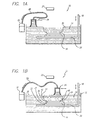
- FIGs 1a and 1b depict schematic representations of a preferred stereolithography apparatus 10 (SLA) for use with the instant invention.
- SLA stereolithography apparatus 10
- the basic components of a stereolithography apparatus are described in US Patent 4,575,330 issued March 11, 1986, to Hull; US Patent 5,184,307 issued February 2, 1993, to Hull, et al; and US Patent 5,182,715 issued January 26, 1993, to Vorgitch, et al. as referenced above.
- the preferred stereolithography apparatus as shown in Figures 1a and 1b includes a container 12 for holding building material 14 (e.g.
- a preferred scanning system is described in several of the patents, applications and publications referenced above including US Patent 5,058,988 issued October 22, 1991, to Spence; US Patent 5,059,021 issued October 22, 1991, to Spence, et al.; US Patent 5,123,734 issued June 23, 1992, to Almquist, et at.; US Patent 5,133,987 issued July 28, 1992, to Spence, et at.; and US Patent 5,840,239 issued November 24, 1998, to Partanen, et al. herein incorporated by reference.
- This preferred system includes the use of a laser, beam expander (may be separate or included in the laser), and a pair of computer controlled XY rotatable scanning mirrors of either the motor driven or galvanometer type.
- a stereolithography apparatus may include a liquid level control system, a build chamber, an environmental control system including a temperature control system, safety interlocks, a viewing device, and the like.
- the instant invention is applicable to object formation using a system that lacks one or more of the elements mentioned herein, and is applicable to a system that includes all elements mentioned herein, or adds additional elements.
- Stereolithography apparatuses on which the instant invention can be utilized are available from 3D Systems, Inc. of Valencia, California. These include stereolithography apparatuses using a HeCd laser operating at 325 nm, and stereolithography apparatus using a solid state laser operating at 354.7 nm.
- Preferred building materials are photopolymerizable materials manufactured by CIBA Specialty Chemicals of Los Angeles, California, and are available from 3D Systems, Inc. These materials manufactured by CIBA Specialty Chemicals include SL 5170, SL 5190, SL 5195, SL 5220, SL 5510, and SL 5520.
- the typical operation of a stereolithography apparatus involves alternating formation of coatings of material (i.e. layers of material) and the selective solidification of those coatings to form an object from a plurality of adhered laminae.
- the process typically begins with the elevator platform 20 immersed approximately one layer thickness below the upper surface 30 of the photopolymerizable material 14.
- the coating of photopolymerizable material is selectively exposed to a beam of stimulation (e.g. UV radiation) which cures the material to a desired depth to form an initial lamina of the object adhered to the elevator platform.
- This initial lamina corresponds to an initial cross-section of the object to be formed or corresponds to supports, which may be used to adhere the object to the platform.
- the elevator platform and adhered initial lamina are lowered a net amount of one layer thickness into the material
- the material may not readily form a coating over the last solidified lamina.
- a recoating device may be swept at, or somewhat above, the surface of the resin (i.e work surface of the material) to aid in the formation of a fresh coating.
- the coating formation process may involve the sweeping of the recoating device one or more times at a desired velocity. After formation of this second coating (i.e. layer of material), a portion of this second layer is solidified by exposure of the medium to stimulation according to data representing the second cross-section of the object.
- layer formation over one portion of a previous lamina may occur simultaneously with exposure of an already formed portion of the coating. This process of coating formation and solidification is repeated over and over again until the object 16 is formed from a plurality of adhered layers (32, 34, 36, 38, 40, 42, and 44) as shown in Figure 1b.
- the stereolithography apparatus may form one or more objects at one time. These objects may be multiple copies, all of the same shape and size, may be two or more different shapes and/or sizes, or may be a combination of copies of similar shapes and sizes or different shapes and/or sizes. Even for a single object, a cross-section may include multiple isolated regions based on object geometry.
- the area of the liquid container generally dictates the number and size of objects formed at one time, although it is possible to "stack" parts in the Z-dimension.
- the solidification process typically consists of the solidification of various regions, which are typically classified as "vector types".
- vector types The use of boundary, hatch, and fill vectors is well known in the art, and taught in a number of the previously cited publications and patents such as previously referenced US Patent 5,321,622 issued June 14, 1994, to Snead, et al.
- the words “vector” and “line” are often used interchangeably, most commonly when referring to a portion of material that has been solidified. In other cases, “vector” refers mainly to the data supplied, while “line” may refer mainly to the solidified portion.
- Boundaries are border regions surrounding an area of a cross section.
- the area may be that of a whole cross-section or a portion of a cross-section.
- Boundaries may be defined, inter alia, to surround up-facing cross-sectional regions, down-facing cross-sectional regions, and continuing cross-sectional regions (regions that face neither up nor down).
- Boundary vectors may be exposed one or more times, or may be offset and exposed one or more times, or may not be exposed at all.
- “Skin Fill”, or “Fill”, or “Skin” is typically an exterior portion of the cross section that faces either upward or downward and is thus an area that is typically completely exposed so as to form a solid surface region.
- "Hatch” is found within continuing regions or boundaries and may or may not be found in down and up facing exterior regions. Hatch may consist of a series of lines, point exposures (i.e. bullets), tiling patterns, or other patterns of exposure. Hatch patterns may result in complete solidification of the boundary regions within which it is used, or may result in partial solidification of those regions. Hatch and skin patterns may consist of overlaid exposures, crossing exposures, or repeated exposures. Hatch and/or fill may be retracted from one or more boundaries. Especially, hatch and/or fill may be retracted from a first boundary that is exposed.
- each lamina of the object can contain one, two or three different regions: (1) down-facing regions; (2) up-facing regions, and/or (3) continuing regions (i.e. regions that are neither down-facing nor up-facing).
- regions (1) down-facing regions; (2) up-facing regions, and/or (3) continuing regions (i.e. regions that are neither down-facing nor up-facing).
- the following eight vector types might be utilized though others may be defined and used:
- the down-facing boundaries, down-facing hatch and down-facing fill define the down-facing regions of the object.
- the up-facing boundaries, up-facing hatch, and up-facing fill define the up-facing regions of the object.
- the continuing boundaries and continuing hatch define the continuing regions of the object.
- Some schemes might involve the use of fewer designations such as: (1) defining only outward facing regions and continuing regions where down-facing and up-facing regions are combined to form the outward facing regions; (2) combining all fill types into a single designation: or (3) combining up-facing and continuing hatch into a single designation or even all three hatch types into a single designation.
- Other schemes might involve the use of more designations such as dividing one or both of the up-facing and down-facing regions into flat regions and near-flat regions, as described in US Patent 5,184,307 issued February 2, 1993, to Hull, et al.
- region identifications might involve the identification of which portions of boundary regions associated with each lamina are outward facing and/or interior to the lamina. Interior boundaries are bounded on both sides by object portions of the lamina whereas outward boundaries are bounded on one side by an object portion of the lamina and on the other side by a non-object portion of the lamina.
- Outward facing boundary regions are associated with the initial cross-section boundaries (i.e. the cross-sectional boundary regions existing prior to dividing them into down-facing, up-facing, and continuing boundary regions) and are described in US Patent 5,321,622 issued June 14, 1994, to Snead, et al. and US Patent 5,597,520 issued January 28, 1997, to Smalley, et al.
- One possible solidification technique begins with exposure of the boundaries. Next, the area inside the boundaries is exposed with hatch vectors and/or fill vectors. This may be accomplished with one or more passes of the laser beam across the area inside the boundaries, but preferably with two passes. In the event that two passes are used, it is preferable that the two passes occur in different, and typically perpendicular, directions. In this case, the first pass of the laser beam scans the object cross-section in a first direction, and the second pass scans the object cross-section in a second direction, generally perpendicular to the first direction. Depending on the position of the cross-section in relationship to the cross-sections above and below it, additional scanning of portions or all of the cross section may be accomplished with fill vectors or the like.
- Another possible solidification technique begins with the scanning of one or more passes of hatch vectors, then any fill vectors necessary, followed with the boundary vectors. Yet another solidification technique may begin with a first pass of hatch vectors in one direction, then the scanning of the boundary vectors, then the second pass of hatch vectors in a second direction, and ending with the fill vectors.
- Solidification techniques may involve the use of raster exposures in one or more directions, or even combinations of vector and raster exposures. Hatch and/or fill may be exposed in patterns that spiral inward or outward or track boundary paths.
- a large variety of solidification techniques may be derived from the above examples, given, for example, that the one or more passes of hatch vectors in one or more directions, one or more passes of boundary vectors, and one or more passes of fill vectors in one or more directions may be performed in various sequences.
- the sequence or sequences chosen may involve exposure of multiple passes of the same vector type in sequence, or may involve separating the multiple passes of the same vector type with exposure of a different vector type or types.
- a relatively narrow beam (e.g. small diameter) may be used for one or more border vectors.
- a relatively narrow beam may be thinner than about 0.500 mm (0.020 inch), and preferably thinner than about 0.380 mm (0.015 inch).
- a relatively wide beam may be used for some border vectors, while a narrower beam is used for other border vectors.
- a relatively wide beam may be wider than about 0.380 mm (0.015 inch), and preferably wider than about 0.500 mm (0.020 inch).
- the relatively wide beam is preferably wider than the relatively narrow beam. Hatch and fill vectors may be drawn with a relatively narrow or relatively wide beam, or with a combination of relatively narrow and relatively wide beams. The determination of whether to use a relatively narrow beam, a relatively wide beam, or a combination, may be generally based on the feature size and/or feature geometry.
- Additional possibilities include solidification by a mask and flood exposure technique, use of deformable mirrors, and other transmissive or reflective light valve techniques.
- the solidification techniques may involve a pause, or delay, after exposure of at least a portion of a cross section.
- a delay may follow the exposure of all or some boundary, hatch, or fill vectors, in one or more directions. This delay may be used as a shrinkage period, where shrinkage results from, inter alia, one or both of chemical bond formation and cooling of the area last solidified by the laser.
- This delay may be determined in any number of ways using various methods and apparatus.
- the delay period may be specified by the user for each build or part of a build, or it may remain fixed until it is changed by the user.
- the delay may be determined by one or a combination of variables, such as 1) material type, as some materials require more delay between scans than other materials, 2) maximum possible area of a cross-section, which may be determined by the area of the stereolithography apparatus platform, 3) area of a last formed cross section or maximum or average area of a group of cross sections, 4) laser power, 5) scan rate, 6) laser profile, 7) beam size, 8) area exposure rate, and/or 9) the measured or calculated temperature of the resin.
- the delay associated with one or more of these variables may be determined experimentally, or possibly automatically. Alternatively, the delay may be a default amount of time independent of these or other variables.
- the lapse of a desired delay time may not be based on evaluation of lapse time from a clock but instead may be based on another parameter which corresponds to a lapse of time (e.g. length of scanning, variation in temperature, and the like).
- the delay may be based on certain conditions being met (e.g. shrinkage observed, optical property observed, lamina(e) temperate, etc.). For example, it may be possible to observe shrinkage, and look for movement to stop or slow to a desired rate.
- a camera or cameras or other optical or electrooptical component(s) may be used to evaluate an optical parameter.
- thermal camera determines where drawing has occurred in the liquid container
- a (regular) camera or sensor that is selectively focused at an area or areas, to look for a change in an optical property (e.g. index of refraction) or for a specified optical property parameter to be met.
- optical property e.g. index of refraction
- an additional object or objects to the platform. which are drawn as the desired time elapses.
- an additional object or objects may be added to the platform, which will be scanned between hatch vector passes of the main object(s), to cause a delay between the hatch vector passes of the main object(s) It is conceivable that different sized additional objects could be used as a means to "control" the desired delay between passes
- the present invention presents techniques for forming highly accurate objects quickly by overcoming distortion problems that can exist when solidifying a photopolymerizable material.
- This invention pertains to both planar lamina formation and fragmented formation stereolithography techniques.
- the techniques of the present invention may have application in the other rapid prototyping technologies for the purposes of reducing distortion and/or speeding object formation.
- the present invention provides techniques for reducing distortion, while at the same time minimizing build time. These techniques include the partial exposure of a layer, then a delay, then completing the exposure of the layer. By inserting a delay between exposures of a layer rather than after the layer is fully exposed, any shrinkage caused by cooling or by chemical bond formation may slow or stop prior to any additional exposure compounding these distortion engines. In addition, it is preferable that the initially exposed material does not adhere to the previously solidified lamina until a subsequent exposure causes adhesion to occur. This lack of adhesion from the first exposure, combined with the delay prior to subsequent exposure, provides heretounforeseen advantages in distortion control.
- the first preferred embodiment of the instant invention involves the formation of a single object on a platform.
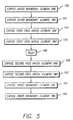
- a first hatch vector pass of the laser beam scans the object cross-section along the X-axis. Upon completion of this pass, a delay period of 15 seconds begins. When the delay period ends, layer scanning begins with hatch vectors along the Y-axis. This embodiment is depicted in the flow chart of Figure 2.
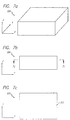
- Figure 3 depicts a side view of an object 98 to be produced stereolithographically.
- this figure depicts the vertical axis (Z) and one of the horizontal axes (X).
- the object 98 includes seven laminae, labeled 100-106 wherein each lamina includes a boundary region labeled B and a hatch region labeled H or a fill region labeled F.
- Object 98 will be used throughout the description of preferred embodiments of the instant invention to illustrate various features associated with those embodiments.
- Object 98 will also be used to illustrate some typical aspects associated with standard stereolithographic practice that will be helpful in understanding the instant invention and its embodiments.
- a 0.100 mm (0.004 inch) thick layer of liquid is prepared in anticipation of the drawing of lamina 103. Examples of techniques usable in this process are described in detail in previously cited and incorporated by reference US Patent 5,174,931 issued December 29, 1992, to Almquist, et al. and U.S. Patent Application 08/790,005, filed January 28, 1997, by Almquist, et al.
- boundary elements 110 are drawn (reference element 50, Figure 2). These boundary elements, as described earlier, outline the borders of the lamina and are typically formed using a vector exposure. The cure depth for these lines is enough to attach these lines to the lamina previously solidified, and is about 0.230 mm (0.009 inch).
- the outer boundary is preferably line width compensated inwardly by approximately one half the width of a cured line of material, which is about 0.125 mm (0.005 inch).
- the first pass of hatch vectors 112 is drawn parallel to the X-axis (reference element 52, Figure 2).
- These vectors are drawn interior to the boundaries, and preferably retracted from the position of the line width compensated boundaries at both their beginning and ending points by an amount greater than one half the line width, for example, about 0.250 mm (0.010 inch). This retraction would preferably prevent the hatch vectors from touching the boundaries. Retraction of hatch vectors from the boundary vectors is described in US Patent 5,321,622 issued June 14, 1994, to Snead, et al. The cure depth for these vectors is preferably slightly less than the layer thickness, for example about 0.075 mm (0.003 inch).
- a delay period (reference element 54, Figure 2) of, for example, 15 seconds begins. As described earlier, this delay allows at least one of the cured material to shrink, and/or any heat that may have built up from the curing process to dissipate. If a second set of vectors were drawn immediately on top of the first set of vectors, the second set of vectors will exhibit affects from their own shrinkage and heat dissipation, as well as residual affects from the lines below them which are still shrinking and cooling. The delay thus leads to a decrease in residual stresses caused by shrinkage and heat dissipation, and a decrease in the associated part distortions.
- a second pass of hatch vectors 112, also interior to the boundary vectors, is drawn parallel to the Y-axis (reference element 56, Figure 2).
- the vectors are preferably retracted at both begin and end points by the same amount as the first pass of hatch vectors.
- the cure depth for these vectors is preferably slightly greater than the layer thickness, for example about 0.125 mm (0.005 inch). As these vectors overlap the vectors along X, the total depth of cure achieved by the points that overlap will be greater than the layer thickness by an amount sufficient to ensure adequate adhesion to the lamina below, for example about 0.075 mm (0.003 inch).
- An additional boundary is then drawn, interior to the first boundary, which bridges any gap between the hatch vectors and the first boundary (reference element 58, Figure 2).
- This inner boundary is offset from the line width compensated position of the first boundary by about one half the width of a boundary vector, so that the boundaries partially overlap each other, for example by about 0.125 mm (0.005 inch).
- the cure depth for this second boundary may be slightly less than the layer thickness, for example about 0.075 mm (0.003 inch). Alternatively, the cure depth for the second boundary may be an amount sufficient to adhere to the lamina below (this will increase build time).
- Preferred parameters used for the formation and exposure of layer 103 appear in Table 1, below. Parameters used for formation and exposure of layer 103. Parameter Approximate Value Used Layer Thickness 0.100 mm (0.004 inch) Outer Boundary Cure Depth 0.230 mm (0.009 inch) Outer Boundary Line Width Compensation 0.125 mm (0.005 inch) First Pass Hatch Cure Depth 0.075 mm (0.003 inch) Delay 15 seconds Second Pass Hatch Cure Depth 0.125 mm (0.005 inch) Hatch Retraction from Compensated Outer Boundary 0.250 mm (0.010 inch) Inner Boundary Cure Depth 0.075 mm (0.003 inch) Inner Boundary Offset from Compensated Outer Boundary 0.125 mm (0.005 inch)
- lamina 103 For lamina 103, scanning is complete, and the layer formation in preparation for lamina 104 may begin. Subsequent laminae are then formed, using the technique described for lamina 103, or may be formed according to some other technique. Examples of other formation techniques are described hereinafter.
- the technique described in the first embodiment ⁇ and the techniques described in the following embodiments and alternatives ⁇ may be applied to up-facing and/or down-facing regions, which may be formed with a plurality of overlaying hatch and/or skin fill exposures.
- the delay may be applied between the first and second of the plurality, and/or between any other members of the plurality
- the layer thickness may be greater or less than 0.100 mm (0.004 inch).
- the layer thicknesses as measured between similar levels (e.g. upper levels) of two consecutive layers can be set to any workable value.
- the thickness between layers may be set to any appropriate amount to yield the desired resolution. Changes in the layer thickness may require changes to other parameters, such as the cure depth values used for various vector types. Any parameter adjustments necessary will be evident to one of skilled in the art upon review of the instant disclosure and may be readily determined experimentally.
- a delay period of any value can be used (e.g. more or less than the 15 seconds used in the above embodiment).
- the desired length of the delay may be set based on a variety of factors described earlier in the introduction section, or may be automatically determined during building with a feedback mechanism, such as those discussed earlier.
- the hatch vectors may be retracted only where their end points meet the boundaries, or only where their start points meet the boundaries. Additionally, the set of hatch vectors may or may not be retracted on its sides, so that the edges do not touch the boundary vectors. The amount of retraction may vary intra-vector, inter-vector, by pass of vectors, by layer, or by range of layers.
- a layer may have just one boundary.
- the curing of a layer may begin with the exposure of the first set of hatch followed by a delay, then the exposure of the second set of hatch, and then finally exposure of the boundary.
- the curing of the layer would begin with exposure of a set of hatch followed by a delay and then exposure of the boundary. In this example, the first set of hatch would once again not adhere to the layer below.
- only one pass of hatch may be used. Another example of this would be to cure a layer starting with an outer boundary which would attach to the layer below, then be followed with a pass of hatch retracted from the boundary. This hatch would not attach to the layer below or to the boundary just drawn. A delay would follow the hatch, then an inner boundary would be drawn attaching the outer boundary and the hatch. This inner boundary may or may not adhere to the layer below.
- Another example of the use of only one pass of hatch would cure a layer beginning with an inner boundary which would not adhere to the layer below. This would be followed by a pass of hatch which may or may not adhere to the boundary just drawn and would not adhere to the layer below. Then a delay would occur followed by an outer boundary which would adhere to the layer below.
- Alternatives might allow otherwise non-adhering boundaries to adhere at one or more locations that are preferably not located on opposite extents of the cross-section being formed.
- the multiple boundaries may directly overlap one another, or may be offset by a fraction of the width of the boundary, or by exactly one boundary width, or more than one boundary width.
- the inner boundary may be drawn first This boundary may have a cure depth slightly less than the layer thickness, but not necessarily. Then the hatch vectors may be drawn, and they may touch the inner boundary at their begin and end points, or only at their begin points, or only at their end points, or may not touch the boundary at all. Then an outer boundary or boundaries may be drawn.
- the boundary vectors may be offset from one another so that they do not touch, are barely touching, or overlap entirely or by some amount.
- first and second passes of hatch vectors for each object/element may be consecutive, or may be separated from one another by one or more additional exposures of one or more vector types.
- An object/element's fill vectors, if any are necessary or desired, may follow the last pass of hatch vectors, or may occur before some, but after other, of the hatch vectors are scanned.
- the order of various passes of hatch and fill vectors, delay period(s), and boundary vectors can vary.
- the first set of hatch vectors include at least one or more points where the cure depth is equal to or greater than the layer thickness ⁇ sufficient to touch and/or adhere to the previous lamina.
- the cure depth of the first set of hatch vectors is less than the layer thickness, it is preferred to have the combined total depth of cure from the first and second set of hatch vectors sufficient to cause adhesion to the lower lamina, although in certain circumstances such adhesion may not be necessary, in which case the net cure depth may be less than the layer thickness.
- the first set of hatch vectors may be scanned in any direction, not necessarily parallel to the X-axis.
- these vectors may be cured to a depth equal to, less than, or greater than the desired layer thickness. It is typical that if cure depth is greater than layer thickness, adhesion occurs and unrestrained shrink cannot occur. However, it is conceivable for certain materials and exposure combinations that a cure depth greater than the layer thickness may be used on the first exposure, and some unconstrained shrink can occur, resulting in reduced distortion of the object.
- the second set of vectors may also be scanned in any direction, not necessarily perpendicular to the first direction, and may have a cure depth equal to, less than, or greater than the desired layer thickness.
- the combined total depth of cure from the first and second set of hatch vectors will be equal to, greater than, or less than the desired layer thickness.
- total depth of cure must be equal to or greater than layer thickness, it is conceivable that for a given material and radiation combination, adhesion may be achieved even when total depth of cure is less than the layer thickness.
- a single direction of hatch may be used, but will be divided into two exposure passes. The first pass will expose every other hatch vector, and the next exposure will expose those vectors intermediate to those first exposed.
- the second preferred embodiment of the instant invention is a continuation of the first embodiment as applied to the formation, on one platform, of more than one object, or an object or objects with multiple cross-sectional elements.
- the techniques described above in the first embodiment are simply followed for each object and/or cross-sectional element, in turn.
- the cure depth values, line width compensation values, and offset values used for lamina 103 in the first embodiment apply equally to the objects and cross-sectional elements of this embodiment. For clarity, this discussion will assume that two objects and/or cross-sectional elements are being built, and that they are both at a position composed of only continuing regions.
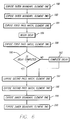
- the second embodiment is depicted in the flow chart of Figure 4.
- the outer boundary is completed for the first object and/or cross-sectional element (reference element 200, Figure 4). Then the first and second hatch vector passes, 122 and 126 of Figure 4, respectively, for the first object/element are drawn, separated by the delay period 124 for the first object/element. Next, the inner boundary 128 for the first object/element is completed.
- the scanning of the boundary 130 of the second object and/or cross-sectional element commences. Then, the two hatch vector passes, 132 and 136 respectively, for the second cross sectional object/element are drawn, with the delay 134 for the second object/element between them. Finally, the inner boundary 138 of the second object and/or cross-sectional element is formed.
- This process is preferably repeated for each object and/or cross-sectional element on the platform, though in some circumstances it may be preferred to use this technique in forming only a portion of the object laminae.
- this technique may be applied to up-facing and/or down-facing regions, which may be formed with a plurality of overlaying hatch and/or skin fill exposures.
- a delay may be applied between the first and second of the plurality, and/or between any other members of the plurality.
- the third preferred embodiment of the instant invention is also a continuation of the first embodiment as applied to the formation, on one platform, of more than one object, or an object or objects with multiple cross-sectional elements. Therefore, this embodiment is, in effect, an alternative to the second embodiment.
- the cure depth values, line width compensation values, and offset values used for lamina 103 in the first embodiment apply equally to the objects and cross-sectional elements of this embodiment. For clarity, this discussion will assume that two objects and/or cross-sectional elements are being built, and that they are both at a position composed of only continuing regions.
- a first implementation of the third embodiment is depicted in the flow chart of Figure 5.
- the outer boundary 150 of the first object and/or cross-sectional element is drawn.
- the outer boundary 152 of the second object/element is completed.
- the first pass of hatch vectors 154 for the first object/element is scanned.
- the first pass of hatch vectors 156 for the second object/element is scanned.
- a delay period 158 begins.
- the delay period ends, the second pass of hatch vectors 160 for the first object/element is scanned.
- the second pass of hatch vectors 162 for the second object/element is scanned.
- the inner boundary 164 of the first object/element is then scanned, followed by the scanning of the inner boundary 166 of the second object/element.
- the delay period begins once the scanning of the first set of hatch vectors 184 for the first object/element is completed. Based on this concept, first the outer boundary 180 of the first object and/or cross-sectional element is drawn. Then the outer boundary 182 of the second object/element is completed. Next, the first pass of hatch vectors 184 for the first object/element is scanned. Upon its completion, the delay period commences 186, and at the same time, scanning commences of the first pass of hatch vectors 188 for the second object/element. Once the delay period is concluded, the first object/element receives a second hatch vector pass 194.
- this process can result in an insufficient amount of delay for cross-sectional elements other than the first cross-sectional element. For instance, if the delay was 15 seconds, a first cross-sectional element took 3 seconds to scan, and a second cross-sectional element took 7 seconds to scan, the effective delay for the second cross-sectional element would only be 11 seconds. This is seen in Table 2 as the elapsed time from completion of drawing the first set of hatch vectors of the second element to the beginning of drawing the second set of hatch vectors of the second element.
- Yet another implementation of the third embodiment involves ensuring the delay for each cross-sectional element separately.
- the time from completion of the first pass of each element until the start of the second pass for each element, respectively would be as long as the desired delay. For example, if the delay was 15 seconds, a first element took 3 seconds to scan, and a second element took 7 seconds to scan, there would be a four second pause between the completion of the second scan of the first element, prior to the beginning of the second scan of the second element, as shown in Table 4
- Time implications of one implementation of the third embodiment Action Estimate d Time Elapsed Time when Action Begun Elapsed Time when Action Complete Draw boundaries of first element 1 sec 0 sec 1 sec Draw boundaries of second element 2 sec 1 sec 3 sec Draw first set of hatch vectors of first element 3 sec 3 sec 6 sec Begin delay for first element 15 sec 6 sec And Draw first set of hatch vectors of second element 7 sec 6 sec 13 sec Begin delay for second element 15 sec 13 sec Complete delay for first element 21 sec Draw second set of hatch vectors of first element 3 sec 21
- the delay is 15 seconds
- the first cross-sectional element takes 12 seconds to scan
- the second cross-sectional element takes 7 seconds to scan
- the third cross-sectional element takes 3 seconds to scan.
- the time elapsed from the completion of the first scan of the first element to the completion of the first scan of the third elements is 10 seconds ⁇ just 5 seconds less than the delay time. Therefore, the second scan of the first element may commence 5 seconds after the completion of the first scan of the third element.
- the time elapsed from the completion of the first scan of the second element to the completion of the second scan of the first element is 20 seconds Therefore, the second scan of the second element may commence immediately upon completion of the second scan of the first element.
- the time elapsed from the completion of the first scan of the third element to the completion of the second scan of the second element is 24 seconds. Therefore, the second scan of the third element may commence immediately upon completion of the second scan of the second element. This situation is depicted in Table 5.
- the effective delay for the second element is 20 seconds
- the effective delay for the third element is 24 seconds
- Another alternative that ensures an adequate delay for each object/element, and uses a single timing element might involve starting the delay after scanning one of the objects/elements wherein the delay time is set equal to the desired delay minus the scan time for the smallest object/element being scanned in forming the lamina.
- the calculated delay may be allowed to elapse before beginning the second pass of exposure over any of the objects/components.
- the delay time is set equal to the desired delay minus an amount no greater than the sum of time that it takes to scan all but the largest of the objects/elements being scanned in forming the lamina.
- the calculated delay may be allowed to elapse prior to beginning the second pass of exposure over any of the objects/components.
- Further embodiments may use more than one timing element to ensure that the rescanning of a given object/element occurs only after the desired delay for the given object/element.
- the delay period for any object/element may be different from that used for other objects/elements. For example, small objects/elements (e.g. objects having cross-sectional dimensions under approximately 1 ⁇ 2 inches) may be given smaller delay times than larger objects (e.g. objects having cross-sectional dimensions greater than 2 ⁇ 4 inches).
- the cross-sectional dimensions may be judged along a direction of scanning individual vectors of the first pass.
- up-facing and/or down-facing regions may be formed with a plurality of overlaying hatch and/or skin fill exposures.
- a delay may be applied between the first and second of the plurality, and/or between any other members of the plurality.
- the fourth preferred embodiment of the instant invention involves decreasing the formation time of an object built with a delay by creating two regions of the object having approximately similar scan times.
- a first hatch vector pass of the laser beam scans the first region.
- the delay begins and a first hatch vector pass of the laser beam scans the second region.
- the second hatch vector pass of the first region commences, followed by the second hatch vector pass of the second region.
- Regions 232 and 234 of object 230 may be treated as regions 224 and 226 of object 220, for the same benefits as shown above.
- the delay for each region might be independently ensured.
- the time from completion of the first pass of each region until the start of the second pass for each region, respectively could be at least as long as the desired delay.
- the first hatch pass for all regions would be followed by any remaining delay for the first region.
- any remaining delay for the second region would be followed by the second hatch pass of the second region.
- the fifth preferred embodiment of the instant invention involves further minimization of build time.
- the drawing speed and direction of the vectors on the first pass and second pass of each region and/or cross-sectional element are taken into consideration when calculating the delay period.
- each point is considered independently, and the order of scanning, and any scanning delays, are calculated to minimize build time while ensuring that at least a majority of twice-or-more-scanned points receive the proper delay between exposures.
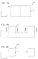
- the first pass of hatch vectors begins at B 1 and ends at E 1 .
- the second pass of hatch vectors begins at B 2 .
- the point at which they intersect is point 246.
- the portion of vector 244 between the beginning of the vector and intersection point 246 is BL 2 .
- the portion of vector 242 between the intersection point 246 and the end of the vector is EL 1 .
- build time may be saved by reducing the delay time by the amount of time it takes to draw EL 1 and BL 2, since Time(B2) ⁇ Time(E 1 ) ⁇ delay ⁇ Time(EL 1 ) ⁇ Time(BL 2 )
- the amount of time saved varies depending on the scan order and the length of the object and the vectors. For instance, the time saved for the lamina in Figure 9c would be less than the time saved for the lamina in Figure 9b, since the length of EL 1 is shorter in Figure 9c. Similarly, the time saved for the lamina in Figure 9d would be less than the time saved for the lamina in Figure 9b or the lamina in Figure 9c.
- the first pass of hatch vectors begins at B 1 and ends at E 1 and the second pass of hatch vectors begins at B 2 .
- the most recently scanned vector it overlaps is vector 252.
- the point at which they intersect is point 256.
- the portion of vector 254 between the beginning of the vector and intersection point 256 is BL 2 .
- the portion of vector 252 between the intersection point 256 and the end of the vector is EL 1 .
- the time to scan EL 1 and BL 2 may be subtracted from the standard delay in order to minimize the time to complete this lamina.
- this check would take place for each vector. For instance, before scanning vector 272, it may be necessary to pause if the time to scan vector 266 between 275 and E 1 , plus the time to scan vectors 268, 269, 270, and 271, when subtracted from the standard delay, is greater than the delay used before scanning vector 268. Thus, this implementation may result in pausing one or more times during the second scan, so that the point on each vector of the second pass with the shortest calculated minimum time between scans can obtain the desired delay.
- this calculation could be completed for each of these points, not just each vector. This may result in pausing one or more times during the second scan, in order for all the points to obtain the desired delay.
- the beam size for exposing at least some of the hatch vectors is preferably about 0.760 mm (0.030 inch) in diameter (for example, between 0.380 mm (0.015 inch) and 3.050 mm (0.120 inch), and more preferably between 0.500 mm (0.020 inch) and 1.524 mm (0.060 inch),
- the laser beam power is preferably about 800 mW (for example, 400 mW or greater)
- the spacing between successive hatch lines is preferably about 0.380 mm (0.015 inch) (for example, between 40 percent and 100 percent of the beam diameter)
- the scanning speed is preferably about 7620 mm/sec (300 ips) (for example, 2540 mm/sec (100 ips) or greater).
- the delay would be implemented according to the following procedure.
- a dual-sized beam would be used.
- the smaller beam would have a diameter of approximately 0.250 mm (0.010 inch), and the larger beam would have a diameter of approximately 0.760 mm (0.030 inch).
- the object would also be formed using a building technique where only portions of some layers are solidified in association with those layers, wherein the remaining portions of the layers would be formed in association with subsequent layers. Such techniques are described in U.S. Patent Application 08/920,428, filed August 29, 1997, by Kruger, et al., US Patent 5,597,520 issued January 28, 1997, to Smalley, et al., and US Patent 5,209,878 issued May 11, 1993, to Smalley, et al. In particular, the object would be formed using two secondary layers located between each primary layer, as described in the above noted U.S. Patent Application 08/920,428, and the separation between each layer would be 0.076 mm (0.003 inch).
- This boundary may also have a cure depth of approximately 0.380 mm (0.015 inch) and be line width compensated by about 0.127 mm (0.005 inch).
- the outer boundary regions of the secondary layers may alternatively be given a cure depth of less than approximately 0.300 mm (0.015 inch).
- the cure depth used may be dependent on the depth of liquid prior to exposure of the boundary regions. For instance, depending on whether or not the outer boundary region where the secondary layer overlays the boundary of the previously formed secondary layer, the depth of liquid prior to exposure may be equal to 0.076 mm (0.003 inch) or 0.152 mm (0.006 inch). Thus, as the depth of liquid prior to exposure varies it may be preferable to adjust the cure depth for these outer boundary regions.
- an inwardly offset boundary 334 would be formed, using the large beam. This boundary may be offset inward from the line width compensated outer boundary position by about 0.380 mm (0.015 inch). The beam would provide an exposure such that the boundary would not adhere to the layer below, but would be given a cure depth of approximately 0.200 mm (0.008 inch).
- a first pass of hatch 336 would be formed within the bounds of the solidified boundary region.
- This hatch would be supplied an exposure yielding a cure depth of approximately 0.200 mm (0.008 inch).
- This hatch may also be retracted slightly from the solidified boundary so that no adhesion to the boundary occurs, or alternatively, it may adhere to the boundary. This adhesion to the boundary could occur at all locations along the boundary or only a portion of the interface region.
- a delay period 338 of, for example, 15 seconds would occur. This delay time may be occupied by drawing other object regions or simply may be a wait period.
- a second exposure of hatch 340 is applied.
- This hatch is preferably oriented in a direction perpendicular to the direction of the first pass of hatch.
- the quantity of exposure applied on the second pass is that amount which would yield a cure depth of 0.250 mm (0.010 inch).
- the spacing between each hatch line is such that an overlapping exposure occurs, yielding a continuously solidified region. Any retraction associated with the second pass of hatch would preferably be similar to that used on the first pass, for example, 0.076 mm (0.003 inch).
- the fifth step would be to use the small spot to expose an outer boundary 342 for the cross-sectional region.
- the exposure would result in a cure depth of approximately 0.380 mm (0.015 inch).
- This outer boundary would be line width compensated by approximately 0.125 mm (0.005 inch).
- the depth of liquid prior to exposure may be equal to 0.076 mm (0.003 inch) or 0.229 mm (0.009 inch). For a shallower depth of liquid prior to exposure, it may be preferable to decrease the cure depth for the outer boundary region.
- the exposure of the primary layer is completed, or there may be additional exposure of hatch, and/or skin fill, and/or supports with the small spot following the small spot exposure of the outer boundary.
- the parameters used for the formation and exposure of layers 200, 202, and 204 appear in Table 8, below. Parameters used for formation and exposure of layers 200, 202, and 204. Parameter Approximate Value Used Layer Thickness, Primary and Secondary Layers 0.076 mm (0.003 inch) Boundary Cure Depth, Secondary Layers 0.380 mm (0.015 inch) Boundary Line Width Compensation, Secondary Layers 0.127 mm (0.005 inch) Inner Boundary Cure Depth, Primary Layer 0.200 mm (0.008 inch) Inner Boundary Offset from Line Width Compensated Outer Boundary, Primary Layer 0.380 mm (0.015 inch) First Hatch Pass Cure Depth, Primary Layer 0.200 mm (0.008 inch) First Hatch Pass Retraction from Inner Boundary, Primary Layer 0.076 mm (0.003 inch) Delay, Primary Layer 15 seconds Second Hatch Pass Cure Depth, Primary Layer 0.250 mm (0.010 inch) Second Hatch Pass Retraction from Inner Boundary, Primary Layer 0.076 mm
- the teachings above it is possible to use the teachings above with a single beam-width laser.
- Some adjustments may be necessary in order to use the above teachings with a single width beam, for instance, the inner boundary offset may preferably be decreased somewhat if the single beam width used were similar to the smaller beam width used in the embodiment.
- the single beam width laser used was similar to the wider of the two beams from the present embodiment, it may be preferable to increase the outer boundary line width compensation value.
- Other necessary adjustments will be obvious to one of skill in the art.
- a second alternative to the above embodiment would cure more than one layer in series according to the teachings above for the primary layer (i.e. secondary layers will not exist). Once again, it may be necessary to adjust certain parameters from the above teaching to effectively utilize this alternative. For example, if the layer thickness for each of these layers were 0.076 mm (0.003 inch), it would be preferable to adjust the cure depth for the first hatch pass to approximately 0.050 mm (0.002 inch). Other necessary adjustments will be evident to those of skill in the art.
- useful delay times may be empirically determined for a given building material and exposure style.
- the geometry of the object, and especially of the last formed lamina may also play a role in selecting appropriate delay times.
- preferred delay times may range from 1 second to 60 second or more. More preferred delay times may be approximately 5 seconds to 30 seconds and most preferred delay times may be about 10 to 20 seconds.
- the most useful delay times may be those that allow a desired amount of shrinkage to occur prior to application of the second exposure.
- these useful delay times may be such as to delay further exposure that may connect an exposed region of a lamina to solidified material that is adhered to the previous lamina.
- the desired amount of shrinkage may be defined as that which maintains curl distortion below a desired limit.
- the extent of curl may be measured using a diagnostic object that includes a cantilevered section extending 14 mm in length, having a width of 3 mm, and having a height of 6 mm.
- the extent of curl may be defined as the ratio of the cantilever's height at its unsupported end to its height at its supported end, for a given cantelever length.
- preferred levels of curl are less than 1%, more preferred levels are less than 0.1%, and most preferred levels are less than 0.01%.
- Techniques for measuring curl distortion are provided in previously referenced US Patent 5,104,592 issued April 14, 1992, to Hull, et al. Delay times may be derived based on the formation of sample parts and analyzing the resulting curl using different delay times.
- the extent of the delay may be based on forming lines of solidified material of desired length (e.g. similar to the dimensions of the objects that will be formed), of desired cure depth (e.g. similar to the cure depth to be used during the first pass over the hatch or fill region that will be used in forming objects), and with desired scanning speeds (e.g. similar to the speeds that will be used during object formation).
- One end of the line may be fixed in position and the other end of the line may be observed as a function of time. As time passes, the free end of the line will move towards the fixed end as shrinkage progresses. From formation of a series of such floating lines, an extent of shrinkage may be ascertained and/or the time it takes for shrinkage to occur may be ascertained.
- the selected delay will be equal to or greater than the time required for 70% of the shrinkage to occur, more preferably the time required for 85% of the shrinkage to occur, and most preferably for 95% of the shrinkage to occur.
- Delay times may be measured by the passing of time on a clock, by the passing of time as derived from some other physical process (e.g. scanning a length of the beam at a desired speed, time to perform other processes such as beam profiling, and the like), and/or by observing physical changes to the object being formed.
- some other physical process e.g. scanning a length of the beam at a desired speed, time to perform other processes such as beam profiling, and the like
- the above embodiments provide simplified techniques that can be used to form objects with less distortion than previously possible, and to form objects with less distortion than that reliably allowed when using high scan rates for solidifying the material.
- the above embodiments also maintain object accuracy while minimizing formation times, maintain temperature uniformity of objects during object formation, and can be used to form objects with faster scan rates than previously possible, while maintaining accuracy.
Abstract
Description
- This invention relates to improved formation of three-dimensional objects from a fluid-like medium on a substantially layer-by-layer basis. The invention more particularly relates to the improved formation of three-dimensional objects by stereolithography utilizing techniques to overcome difficulties in quickly forming objects with minimized distortion.
- Rapid Prototyping and Manufacturing (RP&M) is the name given to a field of technologies that can be used to form three-dimensional objects rapidly and automatically from three-dimensional computer data representing the objects. Rapid prototyping and manufacturing can be considered to include three classes of technologies: (1) stereolithography, (2) selective deposition modeling, and (3) laminated object manufacturing.
- The stereolithography class of technologies creates three-dimensional objects by successively forming layers of a fluid-like medium adjacent to previously formed layers of medium and selectively solidifying these layers to form and adhere laminae (i.e. solidified layers). These laminae are solidified according to cross-sectional data representing successive slices of the three-dimensional object. Typically, adhesion between successive laminae occurs by chemical bond formation between the two laminae (e.g. inter-lamina cross-linking) during polymerization. In alternative embodiments, it is possible that adhesion could occur by application of a separate adhesive or by other mechanical bonding. In summary, adhesion may occur via an adhesive or cohesive phenomenon.
- One specific stereolithography technology is known simply as stereolithography, and it uses a liquid medium that is selectively solidified by exposing it to stimulation. The liquid medium is typically a photopolymerizable material (i.e. resin) and the stimulation is typically visible or ultraviolet electromagnetic radiation. The radiation is typically produced by a laser. Liquid-based stereolithography is disclosed in various patents, applications, and publications, of which a number are briefly described in the Related Patents, Applications and Publications section hereinafter. Another stereolithography technology is known as selective laser sintering (SLS). Selective laser sintering is based on the selective solidification of layers of a powdered medium by exposing the layers to infrared electromagnetic radiation to sinter or fuse the particles. Selective laser sintering is described in US Patent 4,863,538 issued September 5, 1989, to Deckard. A third technology is known as three-dimensional printing (3DP). Three-dimensional printing is based on the selective solidification of layers of a powdered medium which are solidified by the selective deposition of a binder thereon. Three-dimensional printing is described in US Patent 5,204,055 issued April 20, 1993, to Sachs, et al.
- The present invention is primarily directed to stereolithography using liquid-based building materials (i.e. medium). It is believed, in addition, that the techniques of the present invention may have application in the other stereolithography technologies for the purposes of reducing distortion and/or speeding object formation.
- Selective deposition modeling (SDM) involves the build-up of three-dimensional objects by selectively depositing solidifiable material on a lamina-by-lamina basis according to cross-sectional data representing slices of the three-dimensional object. One such technique is called fused deposition modeling (FDM) and involves the extrusion of streams of heated, flowable material which solidify as they are dispensed onto the previously formed laminae of the object. Fused deposition modeling is described in US Patent 5,121,329 issued June 9, 1992, to Crump. Another technique is called ballistic particle manufacturing (BPM) which uses a 5-axis, ink-jet dispenser to direct particles of a material onto previously solidified layers of the object. Ballistic particle manufacturing is described in PCT Publication Nos. WO 96/12607 published May 2, 1996, by Brown, et al.; WO 96/12608 published May 2, 1996, by Brown et al.; WO 96/12609 published May 2, 1996, by Menhennett et al.; and WO 96/12610 published May 2, 1996, by Menhennett et al. A third technique called multijet modeling (MJM) involves the selective deposition of droplets of material from multiple ink jet orifices to speed the building process. Multijet modeling is described in PCT Publication Nos. WO 97/11835 published April 3, 1997, by Earl et al.; and, WO 97/11837 published April 3, 1997, by Leyden et al. (both assigned to 3D Systems, Inc., as is the instant application).
- Laminated object manufacturing (LOM) techniques involve the formation of three-dimensional objects by the stacking, adhering, and selective cuffing, in a selected order, of sheets of material, according to the cross-sectional data representing the three-dimensional object to be formed. Laminated object manufacturing is described in US Patent 4,752,352 issued June 21, 1988, to Feygin; and US Patent 5,015,312 issued May 14, 1991, to Kinzie; and in PCT Publication WO 95/18009 published July 6, 1995, by Morita et al.
- As noted above, the techniques of the instant invention are directed primarily to liquid-based stereolithography object formation. However, it is believed that the techniques may be applied in the selective deposition modeling technologies to reduce object distortion and/or to decrease object formation time. Some of the selective deposition modeling technologies may use a technique sometimes referred to as "Minimum Layer Seconds". This technique requires that a minimum amount of time lapse from the beginning of building one layer to the beginning of building the next layer, so that there is sufficient time for heat built up in the layer to dissipate. If a layer takes less than the Minimum Layer Seconds to build, the balance of the Minimum Layer Seconds is counted down before beginning the next layer. If a delay occurs, it occurs after the layer is completely built. This technique does not teach or suggest the partial creation of a lamina, then a delay, then the completion of the lamina.
- Various techniques for decreasing distortion, and techniques that utilize multiple exposures of an ultraviolet-curable fluid during creation of three-dimensional objects formed using stereolithography, have been described previously, such as, for example: (1) US Patent 5,104,592 issued April 14, 1992, to Hull et al., (2) Japanese Laid Open Patent Application 63-145015A published June 17, 1988, by Itami et al., (3) US Patent 4,945,032 issued July 31, 1990, to Murphy et al., (4) Appendix A of US Patent 4,575,330 issued March 11, 1986, to Hull, (5) European Patent 0 250 121 B1 issued November 2, 1994, to Pomerantz et al., and (6) U.S. Patent Application 08/766,956, filed December 16, 1996, to Gigl et al. assigned to 3D System, Inc.
- US Patent 5,104,592 issued April 14, 1992, to Hull et al., discloses various stereolithography techniques for reducing curl distortion. The first curl reduction technique disclosed is the "dashed line" technique, in which a stereolithography line that is part of a vertical or horizontal formation is drawn with breaks in the line instead of a solid line. Thus, the pulling force normally transmitted along the vector is reduced, and the curl effect is reduced. The second curl reduction technique is the "bent-line" technique, in which a stereolithography line that is part of a vertical or horizontal formation is drawn with bends in the line instead of a straight line. In this way, the pulling force normally transmitted along the vector is reduced, and the curl effect is reduced. The third curl reduction technique is the "secondary structure" technique, in which a stereolithography line which is part of a vertical or horizontal formation is drawn so that it does not adhere directly to the line below or beside it, but is attached, after it is formed, with a secondary structure. As such, the pulling force down the vector is eliminated, the bending moment on adjacent lines is reduced, and the curl effect is reduced.
- One type of secondary structure is known as "rivets" and comprises supporting lines of lower exposure and an area of higher exposure (a "rivet") for connecting support lines from adjacent layers together. The fourth curl reduction technique is the "multipass" technique, in which a stereolithography line which is part of a vertical or horizontal formation is drawn so that it does not adhere directly to the line below or beside it until the material is substantially reacted. In this way, the pulling force down the vector is reduced, the structure is more rigid so it can resist deformation, and the curl effect is reduced. This reference fails to teach a step of ensuring enough time has passed after exposure of a first set of vectors for the shrinkage rate to decline to an acceptable level, prior to exposure of a second set of vectors, let alone teaching the use of a device to count down a desired delay time.
- Japanese Laid Open Patent Application 63-145015A published June 17, 1988, by Itami et al. discloses stereolithography techniques to address inadequate hardness resulting from the small degree of radical polymerization during hardening, and which result in the product being deformed under its own weight. The techniques disclosed irradiate the same position on the liquid photopolymerizable resin material several times at specified time intervals using identical raster exposures. First, a layer of liquid is added to a container (i.e. vat). Then the liquid is irradiated with light which is raster scanned in the "main scanning direction" while moving in the "subscanning direction" in order to partially harden the liquid. The same positions of the resin are raster scanned again at a specified time interval, by raster scanning in the same "main scanning direction" as for the first pass, while moving in the same "subscanning direction" as for the first pass. For each position of the resin, the time interval between the first and second irradiation is the same. The main scanning direction is the direction in which the raster lines cured by the laser beam are situated, and the subscanning direction is the direction in which these raster lines propagate as they are cured next to each other, and is perpendicular to the main scanning direction. The laser beam movement in the main scanning direction is accomplished with the beam reflecting off of a revolving polygon mirror, and the laser beam movement in the subscanning direction is accomplished by either moving the liquid container in the subscanning direction or by reflecting the beam off of a rotating flat mirror. This reference fails to teach curing lines in one direction for a first pass and curing lines in a different direction for a second pass. In addition, this reference fails to teach a step of ensuring enough time has passed after exposure of a first set of vectors for the shrinkage rate to decline to an acceptable level, prior to exposure of a second set of vectors in a different direction than the direction of the first set of vectors, let alone teaching the use of a device to count down a desired delay time.
- US Patent 4,945,032 issued July 31, 1990, to Murphy et al. discloses stereolithography techniques that provide increased strength and solvent resistance of the formed object so distortion is minimized. In preferred practice, these techniques are carried out as a series of repeated, rapid scans of the ultraviolet-curable liquid surface by a computer directed laser light source in the production of each surface layer. This reference fails to teach a step of ensuring enough time has passed after exposure of a first set of vectors for the shrinkage rate to decline to an acceptable level, prior to exposure of a second set of vectors, let alone teaching the use of a device to count down a desired delay time.
- US Patent 4,575,330 issued March 11, 1986, to Hull discloses general stereolithography techniques for generating a three-dimensional object. In the appendix of this patent, multiple irradiation passes are used for forming laminae. There is no mention anywhere in this reference the purpose of the multiple passes nor does there appear to be an intentional delay between irradiation passes. This reference fails to teach the utility of ensuring enough time has passed after exposure of a first set of vectors for the shrinkage rate to decline to an acceptable level, prior to exposure of a second set of vectors, let alone teaching the use of a clock to count down a delay time.
- European Patent 0 250 121 B1 issued November 2, 1994, to Pomerantz et al. discloses a Stereolithography technique for controlling spatial distortion due to shrinkage of the solidifiable material upon solidification. This technique teaches that radiation of the liquid layer is carried out such that as shrinkage occurs, additional solidifiable liquid tends to move into the region vacated by the shrinkage and is solidified. This patent also discloses a Stereolithography technique for reducing the effects of shrinkage. This technique teaches that radiation of the liquid layer may be applied through masks in a two or more step checkerboard pattern to restrict shrinkage at any given time to localized areas, whereby the distortions due to shrinkage following the first step are at least partially compensated during solidification from a subsequent step. This reference fails to teach lack of adhesion on a first pass where adhesion occurs on a subsequent pass. In addition, this reference fails to teach a step of ensuring enough time has passed after exposure of a first set of vectors for the shrinkage rate to decline to an acceptable level, prior to exposure of a second set of overlapping vectors, let alone teaching the use of a device to count down a desired delay time.
- U.S. Patent Application 08/766,956, filed December 16, 1996, to Gigl et al. discloses various Stereolithography techniques for increasing structural integrity while reducing the need for post-curing; for obtaining uniform exposure in regions of intersecting vectors of different types; for determining cure depth; and for reducing distortion due to shrinkage, curl, and post cure.
- In U.S. Patent Application 08/766,956, a stereolithography technique named "tiling" is described. Tiling is a method of forming a lamina of an object produced by stereolithography, wherein the lamina is divided into a series of area elements or tiles. Each area element is isolated from adjacent area elements by spacings. The spacings around each area element remain untransformed, at least until all neighboring area elements or tiles are transformed or solidified. The spacings between the individual tiles are left untransformed to act as stress relief zones. The width of the spacing is typically small compared to the width of the individual tiles.
- U.S. Patent Application 08/766,956 discloses that it has long been suspected and recently experimentally verified that shrinkage of curing material can still be occurring several seconds after exposure of an area is suspended. The application states that, as the building material is cured, using preferred materials (XB 5081), there is a delay of approximately 2-3 seconds prior to shrinkage of the material. Thus, the application suggests that the grouting between the tiles is cured after the tiles have been allowed to shrink (e.g., generally at least a 3-second delay between completing neighboring tiles and beginning to grout). In addition, it teaches that the tiles can be partially cured (e.g., a one line trace) followed by partial curing of other tiles, and then returning one or more times to fully cure the previously partially cured tiles.
- Another embodiment of U.S. Patent Application 08/766,956 forms a lamina on which the gaps will be closed by floating at least one end of the solidified material which spans the gap until after at least a substantial portion of the shrinkage has occurred. After allowing for shrinkage to occur, the floating end(s) can be tacked down with rivets, or multipass, or the like.
- It is also taught in U.S. Patent Application 08/766,956 that long vectors can cause tremendous amounts of curl if they are cured and adhered to a previous layer while they are still shrinking. In the case of a floating vector, it may occur where the ends of the vector attach to a boundary. A distortion reduction technique called "ACES" is described. Using ACES, the first set of skin vectors exposed is given an exposure that results in a net cure depth of slightly under one layer thickness. When the second set of vectors expose the material, the increase in cure depth results in adhesion. When using epoxy resins like SL 5170 and SL 5180, it has been found helpful to allow a time period of between 5 and 90 seconds after exposure of each cross-section before beginning the recoating process so as to allow the modulus of the exposed resin to increase to a certain minimum level before subjecting the newly exposed layer to the forces involved in recoating. This time period is called "predip delay". As a technique for eliminating or at least minimizing the impact that predip delay has on part building time, it is possible to use a smart exposure pattern that exposes critical areas first, followed by exposure of less critical areas. In effect, the count down of the predip delay time can begin as soon as all critical regions have been exposed.
- Another distortion reduction technique disclosed is called "log jam". "Log Jam" refers to a scanning technique where some internal hatch (or fill) vectors are retracted from the layer borders to avoid adhesion, wherein after exposure of the hatch or fill an offset border or the like is scanned to attach the hatch and original border.
- This reference fails to teach the utility of ensuring enough time has passed after exposure of a first set of vectors for the shrinkage rate to decline to an acceptable level, prior to exposure of a second set of perpendicularly overlapping vectors, let alone teaching the use of a clock to count down a delay time between exposures of perpendicularly overlapping vectors on one layer.
- All publications, applications and patents referred to in this section are hereby incorporated by reference as if set forth in full.
- A need exists in the art for simplified techniques that can be used to rapidly form objects with less distortion than previously possible, and more particularly, with less distortion than was reliably allowed when using high scan rates for solidifying the material.
- The patents, applications and publications in the following Table 1 are hereby incorporated by reference as if set forth in full. Table 1 provides a table of patents and applications co-owned by the assignee of the instant application. A brief description of subject matter found in each patent, application and publication is included in the table to aid the reader in finding specific types of teachings. It is not intended that the incorporation of subject matter be limited to those topics specifically indicated, but instead the incorporation is to include all subject matter found in these publications, applications and patents. The teachings in these incorporated references can be combined with the teachings of the instant application in many ways. For example, the references directed to various data manipulation techniques may be combined with the teachings herein to derive even more useful, modified object data that can be used to more accurately and/or efficiently form objects. As another example, the various apparatus configurations disclosed in these references may be used in conjunction with the novel features of the instant invention.


- The following two books are also incorporated by reference herein as if set forth in full: (1) Rapid Prototyping and Manufacturing: Fundamentals of Stereolithography, by Paul F. Jacobs; published by the Society of Manufacturing Engineers, Dearborn Ml; 1992; and (2) Stereolithography and other RP&M Technologies: from Rapid Prototyping to Rapid Tooling; by Paul F. Jacobs; published by the Society of Manufacturing Engineers, Dearborn Ml; 1996.
- A first aspect of the invention is to provide a method of forming at least a portion of a three-dimensional object, including: a) forming a layer of fluid-like material over a previously formed lamina of the object, b) exposing the layer to stimulation to form a subsequent lamina of the object adhered to the previously formed lamina, c) repeating (a) and (b) to form the object from a plurality of adhered laminae, and d) defining a time period. Exposing the layer includes exposing at least one element of one layer with at least two exposures. A first exposure is followed by a second exposure after lapse substantially equal to or greater than the defined time period. The first exposure is performed by a beam scanning in a first direction over the element and the second exposure is performed by the beam scanning in a second direction over the element. The first and second directions are different.
- A second aspect of the invention is to provide a method of forming at least a portion of a three-dimensional object including: a) forming a layer of fluid-like material over a previously formed lamina of the object, b) exposing the layer to stimulation to form a subsequent lamina of the object adhered to the previously formed lamina, c) repeating (a) and (b) to form the object from a plurality of adhered laminae, and d) defining a time period (DTP). At least one lamina to be formed includes at least first and second isolated regions. Exposing the layer includes exposing the layer with at least first and second exposures. A first exposure of the first region is completed at a time CT11 and the first exposure of the second region is completed at a time CT21 and a second exposure of the first region begins at a time BT12 and the second exposure of the second region begins at a time BT22 fulfilling the equations, DTP ∼≤ BT12- CT11, and DTP ∼≤ BT22- CT21, where CT11, CT21, BT12, and BT22 follow after one another respectively.
- A third aspect of the invention is to provide a method for forming at least a portion of a three-dimensional object including: a) forming a layer of fluid-like material over a previously formed lamina of the object, b) exposing the layer to stimulation to form a subsequent lamina of the object adhered to the previously formed lamina, c) repeating (a) and (b) to form the object from a plurality of adhered laminae, and d) defining a time period. Exposing the layer includes exposing at least one element of one layer with at least two exposures. A first exposure is completed at a time T1 and a second exposure begins at a time T2 and the difference between T1 and T2 is substantially equal to or greater than the defined time period.
- A fourth aspect of the invention is to provide a method for forming at least a portion of a three-dimensional object including: a) forming a layer of fluid-like material over a previously formed lamina of the object, b) exposing the layer to stimulation to form a subsequent lamina of the object adhered to the previously formed lamina, c) repeating (a) and (b) to form the object from a plurality of adhered laminae, and d) defining a time period. At least one lamina to be formed includes at least two regions and exposing the layer includes exposing the layer with at least two exposures. A first exposure exposes a first region and at least a second region, and the at least second exposure exposes a first region and at least a second region. The time between the completion of the first exposure of at least one of the exposed regions and the beginning of the second exposure of the exposed region is substantially equal to or greater than the defined time period.
- A fifth aspect of the invention is to provide a method for forming at least a portion of a three-dimensional object, including: a) forming a layer of fluid-like material over a previously formed lamina of the object, b) exposing the layer to stimulation to form a subsequent lamina of the object adhered to the previously formed lamina, c) repeating (a) and (b) to form the object from a plurality of adhered laminae, and d) defining a time period. Exposing the layer includes exposing at least one point of one layer with at least two exposures. A first exposure is followed by a second exposure after lapse of the defined time period. The first exposure is performed by a beam scanning in a first direction over the element. The second exposure is performed by a beam scanning in a second direction over the element. The first and second directions are different, and at least one point receives a first exposure at a time T1, and a second exposure at a time T2 according to the equation T2 - T1 ∼≥ DTP, wherein T1 and T2 follow one another consecutively.
- A sixth aspect of the invention is to provide an apparatus for forming at least a portion of a three-dimensional object, including a) a coating system for forming a layer of fluid-like material over a previously formed lamina of the object, b) an exposure system for forming a subsequent lamina of the object adhered to the previously formed lamina, c) a computer programmed to operate (a) and (b) to form the object from a plurality of adhered laminae, and d) a computer programmed to utilize a defined time period. The exposure system is operated to form at least one element of one layer with at least two exposures. A first exposure is completed at a time T1 and a second exposure begins at a time T2 and the difference between T1 and T2 is substantially equal to or greater than the defined time period.
- A seventh aspect of the invention is to provide an apparatus for forming at least a portion of a three-dimensional object, including a) means for forming a layer of fluid-like material over a previously formed lamina of the object, b) means for forming a subsequent lamina of the object adhered to the previously formed lamina, c) means for operating (a) and (b) to form the object from a plurality of adhered laminae, and d) means for defining a time period. The means for forming a subsequent lamina is operated to form at least one element of one layer with at least two exposures. A first exposure is completed at a time T1 and a second exposure begins at a time T2 and the difference between T1 and T2 is substantially equal to or greater than the defined time period.
- Other aspects of the invention supply apparatus for implementing the method aspects of the invention noted above.
Additional aspects of the invention will be clear from the embodiments of the invention described below, in conjunction with the Figures associated therewith. Further aspects of the invention involve those referenced above as well as other aspects, to be practiced alone and in various combinations with one another. -
- Figures 1a and 1b depict side views of a preferred stereolithography apparatus for practicing the instant invention.
- Figure 2 is a flow chart depicting the first embodiment.
- Figure 3 is side view of an object to be produced stereolithographically according to the teachings of the first embodiment.
- Figure 4 is a flow chart depicting the second embodiment.
- Figure 5 is a flow chart depicting one implementation of the third embodiment.
- Figure 6 is a flow chart depicting one implementation of the third embodiment.
- Figure 7a is an oblique view of a generally rectangular object to be produced stereolithographically.
- Figure 7b is a side view of a generally rectangular object to be produced stereolithographically.
- Figure 7c is a section view taken along the line 7c-7c of Figure 7b.
- Figure 7d is a top view of a generally rectangular object to be produced stereolithographically.
- Figure 8a is a side view of a generally U-shaped object to be produced stereolithographically.
- Figure 8b is a section view taken along the
lines 8b-8b of Figure 8a. - Figure 9a is an oblique view of a generally cube-shaped object to be produced stereolithographically.
- Figure 9b, 9c, and 9d are section views taken along the
line 9b-9b of Figure 9a. - Figure 10a is an oblique view of a generally L-shaped object to be produced stereolithographically.
- Figure 10b and 10c are section views taken along the line 10b-10b of Figure 10a.
- Figure 11 is a side view of an object to be produced stereolithographically according to the teachings of the sixth embodiment.
- Figure 12 is a a flow chart depicting the sixth embodiment.
-
- Figures 1a and 1b depict schematic representations of a preferred stereolithography apparatus 10 (SLA) for use with the instant invention. The basic components of a stereolithography apparatus are described in US Patent 4,575,330 issued March 11, 1986, to Hull; US Patent 5,184,307 issued February 2, 1993, to Hull, et al; and US Patent 5,182,715 issued January 26, 1993, to Vorgitch, et al. as referenced above. The preferred stereolithography apparatus as shown in Figures 1a and 1b includes a
container 12 for holding building material 14 (e.g. photopolymerizable material) from which anobject 16 will be formed, anelevator 18 and elevator driving system (not shown), anelevator platform 20, anexposure system 22, a recoatingbar 24 and recoating bar driving system (not shown), and at least one computer for manipulating object data (as needed) and for controlling the exposure system, elevator, and recoating devices. - A preferred scanning system is described in several of the patents, applications and publications referenced above including US Patent 5,058,988 issued October 22, 1991, to Spence; US Patent 5,059,021 issued October 22, 1991, to Spence, et al.; US Patent 5,123,734 issued June 23, 1992, to Almquist, et at.; US Patent 5,133,987 issued July 28, 1992, to Spence, et at.; and US Patent 5,840,239 issued November 24, 1998, to Partanen, et al. herein incorporated by reference. This preferred system includes the use of a laser, beam expander (may be separate or included in the laser), and a pair of computer controlled XY rotatable scanning mirrors of either the motor driven or galvanometer type.
- Preferred control and data manipulation systems and software are described in a number of the patents referenced above, including US Patent 5,184,307 issued February 2, 1993, to Hull, et al.; US Patent 5,321,622 issued June 14, 1994, to Snead, et al.; and US Patent 5,597,520 issued January 28, 1997, to Smalley, et al. herein incorporated by reference. A preferred recoating device is described in US Patent No. 5,902,537, issued May 11, 1999, Almquist, et al. as referenced above and includes
recoater bar 24,regulated vacuum pump 26, andvacuum line 28 connecting thebar 24 and thepump 26. - Other components of a stereolithography apparatus (not shown) may include a liquid level control system, a build chamber, an environmental control system including a temperature control system, safety interlocks, a viewing device, and the like.
- It should be understood that the instant invention is applicable to object formation using a system that lacks one or more of the elements mentioned herein, and is applicable to a system that includes all elements mentioned herein, or adds additional elements.
- Stereolithography apparatuses on which the instant invention can be utilized are available from 3D Systems, Inc. of Valencia, California. These include stereolithography apparatuses using a HeCd laser operating at 325 nm, and stereolithography apparatus using a solid state laser operating at 354.7 nm. Preferred building materials are photopolymerizable materials manufactured by CIBA Specialty Chemicals of Los Angeles, California, and are available from 3D Systems, Inc. These materials manufactured by CIBA Specialty Chemicals include SL 5170, SL 5190, SL 5195, SL 5220, SL 5510, and SL 5520.
- The typical operation of a stereolithography apparatus involves alternating formation of coatings of material (i.e. layers of material) and the selective solidification of those coatings to form an object from a plurality of adhered laminae. The process typically begins with the
elevator platform 20 immersed approximately one layer thickness below theupper surface 30 of thephotopolymerizable material 14. The coating of photopolymerizable material is selectively exposed to a beam of stimulation (e.g. UV radiation) which cures the material to a desired depth to form an initial lamina of the object adhered to the elevator platform. This initial lamina corresponds to an initial cross-section of the object to be formed or corresponds to supports, which may be used to adhere the object to the platform. After formation of this initial lamina the elevator platform and adhered initial lamina are lowered a net amount of one layer thickness into the material - As the material is typically viscous, and the thickness of each layer is very thin (e.g. 0.025 mm to 0.250 mm (0.001 to 0.010 inch)), the material may not readily form a coating over the last solidified lamina. In the case where a coating is not readily formed a recoating device may be swept at, or somewhat above, the surface of the resin (i.e work surface of the material) to aid in the formation of a fresh coating. The coating formation process may involve the sweeping of the recoating device one or more times at a desired velocity. After formation of this second coating (i.e. layer of material), a portion of this second layer is solidified by exposure of the medium to stimulation according to data representing the second cross-section of the object. In alternative processes, layer formation over one portion of a previous lamina may occur simultaneously with exposure of an already formed portion of the coating. This process of coating formation and solidification is repeated over and over again until the
object 16 is formed from a plurality of adhered layers (32, 34, 36, 38, 40, 42, and 44) as shown in Figure 1b. - The stereolithography apparatus may form one or more objects at one time. These objects may be multiple copies, all of the same shape and size, may be two or more different shapes and/or sizes, or may be a combination of copies of similar shapes and sizes or different shapes and/or sizes. Even for a single object, a cross-section may include multiple isolated regions based on object geometry. The area of the liquid container generally dictates the number and size of objects formed at one time, although it is possible to "stack" parts in the Z-dimension.
- The solidification process typically consists of the solidification of various regions, which are typically classified as "vector types". The use of boundary, hatch, and fill vectors is well known in the art, and taught in a number of the previously cited publications and patents such as previously referenced US Patent 5,321,622 issued June 14, 1994, to Snead, et al. The words "vector" and "line" are often used interchangeably, most commonly when referring to a portion of material that has been solidified. In other cases, "vector" refers mainly to the data supplied, while "line" may refer mainly to the solidified portion.
- Briefly, "boundaries" are border regions surrounding an area of a cross section. The area may be that of a whole cross-section or a portion of a cross-section. Boundaries may be defined, inter alia, to surround up-facing cross-sectional regions, down-facing cross-sectional regions, and continuing cross-sectional regions (regions that face neither up nor down). Boundary vectors may be exposed one or more times, or may be offset and exposed one or more times, or may not be exposed at all.
- "Skin Fill", or "Fill", or "Skin", is typically an exterior portion of the cross section that faces either upward or downward and is thus an area that is typically completely exposed so as to form a solid surface region. "Hatch" is found within continuing regions or boundaries and may or may not be found in down and up facing exterior regions. Hatch may consist of a series of lines, point exposures (i.e. bullets), tiling patterns, or other patterns of exposure. Hatch patterns may result in complete solidification of the boundary regions within which it is used, or may result in partial solidification of those regions. Hatch and skin patterns may consist of overlaid exposures, crossing exposures, or repeated exposures. Hatch and/or fill may be retracted from one or more boundaries. Especially, hatch and/or fill may be retracted from a first boundary that is exposed.
- In one classification scheme (as described in US Patent 5,321,622 issued June 14, 1994, to Snead, et al.) each lamina of the object can contain one, two or three different regions: (1) down-facing regions; (2) up-facing regions, and/or (3) continuing regions (i.e. regions that are neither down-facing nor up-facing). In this scheme, the following eight vector types might be utilized though others may be defined and used:
- Down-facing boundaries
- Boundaries that surround down-facing regions of the object.
- Up-facing boundaries
- Boundaries that surround up-facing regions of the object.
- Continuing boundaries
- Boundaries that surround regions of the object that are neither up-facing nor down-facing
- Down-facing Hatch
- Lines of exposure that are positioned within the down-facing boundaries. These lines may be closely or widely spaced from one another and may extend in one or more directions.
- Up-facing Hatch
- Lines of exposure that are positioned within the up-facing boundaries. These lines may be closely or widely spaced from one another and may extend in one or more directions.
- Continuing Hatch
- Lines of exposure that are positioned within continuing boundaries. These lines may be closely or widely spaced from one another and may extend in one or more directions.
- Down-facing Skin/Fill
- Lines of exposure that are positioned within the down-facing boundaries and closely spaced so as to form a continuous region of solidified material.
- Up-facing Skin/Fill
- Lines of exposure that are positioned within the up-facing boundaries and closely spaced so as to form a continuous region of solidified material.
- Taken together, the down-facing boundaries, down-facing hatch and down-facing fill define the down-facing regions of the object. The up-facing boundaries, up-facing hatch, and up-facing fill define the up-facing regions of the object. The continuing boundaries and continuing hatch define the continuing regions of the object.
- Other schemes for region identification and vector type creation are described in various patents and applications referenced above, including US Patent 5,184,307 issued February 2, 1993, to Hull, et al.; US Patent 5,209,878 issued May 11, 1993, to Smalley, et at.; US Patent 5,238,639 issued August 24, 1993, to Vinson, et at.; US Patent 5,597,520 issued January 28, 1997, to Smalley, et al.; and PCT Publication PCT Publication WO 97/11837 published April 3, 1997, by Leyden, et al. and PCT Publication WO 98/51478 published November 19, 1998, by Nguyen. Some schemes might involve the use of fewer designations such as: (1) defining only outward facing regions and continuing regions where down-facing and up-facing regions are combined to form the outward facing regions; (2) combining all fill types into a single designation: or (3) combining up-facing and continuing hatch into a single designation or even all three hatch types into a single designation. Other schemes might involve the use of more designations such as dividing one or both of the up-facing and down-facing regions into flat regions and near-flat regions, as described in US Patent 5,184,307 issued February 2, 1993, to Hull, et al.
- Other region identifications might involve the identification of which portions of boundary regions associated with each lamina are outward facing and/or interior to the lamina. Interior boundaries are bounded on both sides by object portions of the lamina whereas outward boundaries are bounded on one side by an object portion of the lamina and on the other side by a non-object portion of the lamina. Outward facing boundary regions are associated with the initial cross-section boundaries (i.e. the cross-sectional boundary regions existing prior to dividing them into down-facing, up-facing, and continuing boundary regions) and are described in US Patent 5,321,622 issued June 14, 1994, to Snead, et al. and US Patent 5,597,520 issued January 28, 1997, to Smalley, et al.
- Various solidification techniques may be used to expose the medium to stimulation. One possible solidification technique begins with exposure of the boundaries. Next, the area inside the boundaries is exposed with hatch vectors and/or fill vectors. This may be accomplished with one or more passes of the laser beam across the area inside the boundaries, but preferably with two passes. In the event that two passes are used, it is preferable that the two passes occur in different, and typically perpendicular, directions. In this case, the first pass of the laser beam scans the object cross-section in a first direction, and the second pass scans the object cross-section in a second direction, generally perpendicular to the first direction. Depending on the position of the cross-section in relationship to the cross-sections above and below it, additional scanning of portions or all of the cross section may be accomplished with fill vectors or the like.
- Another possible solidification technique begins with the scanning of one or more passes of hatch vectors, then any fill vectors necessary, followed with the boundary vectors. Yet another solidification technique may begin with a first pass of hatch vectors in one direction, then the scanning of the boundary vectors, then the second pass of hatch vectors in a second direction, and ending with the fill vectors.
- It is also possible that more than one pass of boundary or fill vectors is desirable, that multiple passes of fill vectors may be in one or more directions, and/or that multiple passes of boundary vectors may be offset from one another. Other solidification techniques may use fill vectors, and no hatch vectors, or may use hatch vectors, and no fill vectors. These techniques may or may not include the use of one or more boundary vectors.
- Other solidification techniques may involve the use of raster exposures in one or more directions, or even combinations of vector and raster exposures. Hatch and/or fill may be exposed in patterns that spiral inward or outward or track boundary paths.
- A large variety of solidification techniques may be derived from the above examples, given, for example, that the one or more passes of hatch vectors in one or more directions, one or more passes of boundary vectors, and one or more passes of fill vectors in one or more directions may be performed in various sequences. The sequence or sequences chosen may involve exposure of multiple passes of the same vector type in sequence, or may involve separating the multiple passes of the same vector type with exposure of a different vector type or types.
- In some embodiments, different sized beams may be used for exposing a layer. A relatively narrow beam (e.g. small diameter) may be used for one or more border vectors. A relatively narrow beam may be thinner than about 0.500 mm (0.020 inch), and preferably thinner than about 0.380 mm (0.015 inch). Alternatively, a relatively wide beam may be used for some border vectors, while a narrower beam is used for other border vectors. A relatively wide beam may be wider than about 0.380 mm (0.015 inch), and preferably wider than about 0.500 mm (0.020 inch). The relatively wide beam is preferably wider than the relatively narrow beam. Hatch and fill vectors may be drawn with a relatively narrow or relatively wide beam, or with a combination of relatively narrow and relatively wide beams. The determination of whether to use a relatively narrow beam, a relatively wide beam, or a combination, may be generally based on the feature size and/or feature geometry.
- Additional possibilities include solidification by a mask and flood exposure technique, use of deformable mirrors, and other transmissive or reflective light valve techniques.
- In addition, the solidification techniques may involve a pause, or delay, after exposure of at least a portion of a cross section. A delay may follow the exposure of all or some boundary, hatch, or fill vectors, in one or more directions. This delay may be used as a shrinkage period, where shrinkage results from, inter alia, one or both of chemical bond formation and cooling of the area last solidified by the laser.
- This delay may be determined in any number of ways using various methods and apparatus. The delay period may be specified by the user for each build or part of a build, or it may remain fixed until it is changed by the user. Alternatively, the delay may be determined by one or a combination of variables, such as 1) material type, as some materials require more delay between scans than other materials, 2) maximum possible area of a cross-section, which may be determined by the area of the stereolithography apparatus platform, 3) area of a last formed cross section or maximum or average area of a group of cross sections, 4) laser power, 5) scan rate, 6) laser profile, 7) beam size, 8) area exposure rate, and/or 9) the measured or calculated temperature of the resin. The delay associated with one or more of these variables may be determined experimentally, or possibly automatically. Alternatively, the delay may be a default amount of time independent of these or other variables.
- The lapse of a desired delay time may not be based on evaluation of lapse time from a clock but instead may be based on another parameter which corresponds to a lapse of time (e.g. length of scanning, variation in temperature, and the like). As a further alternative, the delay may be based on certain conditions being met (e.g. shrinkage observed, optical property observed, lamina(e) temperate, etc.). For example, it may be possible to observe shrinkage, and look for movement to stop or slow to a desired rate. Alternatively, a camera or cameras or other optical or electrooptical component(s) may be used to evaluate an optical parameter. For instance, it may be possible to use a thermal camera to determine where drawing has occurred in the liquid container, followed by use of a (regular) camera or sensor that is selectively focused at an area or areas, to look for a change in an optical property (e.g. index of refraction) or for a specified optical property parameter to be met.
- During this delay, it is possible that some overhead item or items, such as for instance laser beam profiling, may be performed so that total time per layer is reduced. Instead of or in addition to overhead items, boundaries may be drawn during the delay to decrease overall time per layer.
- In addition, it is possible to add an additional object or objects to the platform. which are drawn as the desired time elapses. Put another way, an additional object or objects may be added to the platform, which will be scanned between hatch vector passes of the main object(s), to cause a delay between the hatch vector passes of the main object(s) It is conceivable that different sized additional objects could be used as a means to "control" the desired delay between passes
- The present invention presents techniques for forming highly accurate objects quickly by overcoming distortion problems that can exist when solidifying a photopolymerizable material. This invention pertains to both planar lamina formation and fragmented formation stereolithography techniques. As mentioned above, it is believed that the techniques of the present invention may have application in the other rapid prototyping technologies for the purposes of reducing distortion and/or speeding object formation.
- The present invention provides techniques for reducing distortion, while at the same time minimizing build time. These techniques include the partial exposure of a layer, then a delay, then completing the exposure of the layer. By inserting a delay between exposures of a layer rather than after the layer is fully exposed, any shrinkage caused by cooling or by chemical bond formation may slow or stop prior to any additional exposure compounding these distortion engines. In addition, it is preferable that the initially exposed material does not adhere to the previously solidified lamina until a subsequent exposure causes adhesion to occur. This lack of adhesion from the first exposure, combined with the delay prior to subsequent exposure, provides heretounforeseen advantages in distortion control.
- We next turn our attention to specific preferred embodiments of the instant invention that will be described in view of the preliminary information and background provided above. The headers associated with the following embodiments are intended to aid reading this disclosure but are not intended to isolate or limit the applicability of the teachings herein to those individual embodiments in connection with which explicit disclosure is made.
- The first preferred embodiment of the instant invention involves the formation of a single object on a platform. A first hatch vector pass of the laser beam scans the object cross-section along the X-axis. Upon completion of this pass, a delay period of 15 seconds begins. When the delay period ends, layer scanning begins with hatch vectors along the Y-axis. This embodiment is depicted in the flow chart of Figure 2.
- Referring now to Figure 3, this process is described in more detail. Figure 3 depicts a side view of an object 98 to be produced stereolithographically. In terms of forming horizontal layers, this figure depicts the vertical axis (Z) and one of the horizontal axes (X). As illustrated, the object 98 includes seven laminae, labeled 100-106 wherein each lamina includes a boundary region labeled B and a hatch region labeled H or a fill region labeled F. Object 98 will be used throughout the description of preferred embodiments of the instant invention to illustrate various features associated with those embodiments. Object 98 will also be used to illustrate some typical aspects associated with standard stereolithographic practice that will be helpful in understanding the instant invention and its embodiments.
- We will focus on the process of building
lamina 103 with the techniques of the present invention. This description of the first embodiment―and the descriptions of the additional embodiments and alternatives to follow―applies to the formation of continuing regions of object cross-sections. These regions are bounded from below by the previous lamina and above by the next lamina. The descriptions of the embodiments do not apply to the formation of down-facing or up-facing regions. - First, a 0.100 mm (0.004 inch) thick layer of liquid is prepared in anticipation of the drawing of
lamina 103. Examples of techniques usable in this process are described in detail in previously cited and incorporated by reference US Patent 5,174,931 issued December 29, 1992, to Almquist, et al. and U.S. Patent Application 08/790,005, filed January 28, 1997, by Almquist, et al. Once the liquid layer is prepared,boundary elements 110 are drawn (reference element 50, Figure 2). These boundary elements, as described earlier, outline the borders of the lamina and are typically formed using a vector exposure. The cure depth for these lines is enough to attach these lines to the lamina previously solidified, and is about 0.230 mm (0.009 inch). Unless otherwise stated in the teachings herein, when a quantity of exposure is referred to in terms of cure depth, the quantity is that which would be obtained had no other exposure occurred. As taught in incorporated by reference US Patent 5,184,307 issued February 2, 1993, to Hull, et al., the outer boundary is preferably line width compensated inwardly by approximately one half the width of a cured line of material, which is about 0.125 mm (0.005 inch). - Next, the first pass of
hatch vectors 112 is drawn parallel to the X-axis (reference element 52, Figure 2). These vectors are drawn interior to the boundaries, and preferably retracted from the position of the line width compensated boundaries at both their beginning and ending points by an amount greater than one half the line width, for example, about 0.250 mm (0.010 inch). This retraction would preferably prevent the hatch vectors from touching the boundaries. Retraction of hatch vectors from the boundary vectors is described in US Patent 5,321,622 issued June 14, 1994, to Snead, et al. The cure depth for these vectors is preferably slightly less than the layer thickness, for example about 0.075 mm (0.003 inch). - Upon completion of scanning of the hatch vectors along the X-axis, a delay period (
reference element 54, Figure 2) of, for example, 15 seconds begins. As described earlier, this delay allows at least one of the cured material to shrink, and/or any heat that may have built up from the curing process to dissipate. If a second set of vectors were drawn immediately on top of the first set of vectors, the second set of vectors will exhibit affects from their own shrinkage and heat dissipation, as well as residual affects from the lines below them which are still shrinking and cooling. The delay thus leads to a decrease in residual stresses caused by shrinkage and heat dissipation, and a decrease in the associated part distortions. - Upon lapse of the delay, a second pass of
hatch vectors 112, also interior to the boundary vectors, is drawn parallel to the Y-axis (reference element 56, Figure 2). The vectors are preferably retracted at both begin and end points by the same amount as the first pass of hatch vectors. The cure depth for these vectors is preferably slightly greater than the layer thickness, for example about 0.125 mm (0.005 inch). As these vectors overlap the vectors along X, the total depth of cure achieved by the points that overlap will be greater than the layer thickness by an amount sufficient to ensure adequate adhesion to the lamina below, for example about 0.075 mm (0.003 inch). - An additional boundary is then drawn, interior to the first boundary, which bridges any gap between the hatch vectors and the first boundary (
reference element 58, Figure 2). This inner boundary is offset from the line width compensated position of the first boundary by about one half the width of a boundary vector, so that the boundaries partially overlap each other, for example by about 0.125 mm (0.005 inch). The cure depth for this second boundary may be slightly less than the layer thickness, for example about 0.075 mm (0.003 inch). Alternatively, the cure depth for the second boundary may be an amount sufficient to adhere to the lamina below (this will increase build time). - Preferred parameters used for the formation and exposure of
layer 103 appear in Table 1, below.Parameters used for formation and exposure of layer 103.Parameter Approximate Value Used Layer Thickness 0.100 mm (0.004 inch) Outer Boundary Cure Depth 0.230 mm (0.009 inch) Outer Boundary Line Width Compensation 0.125 mm (0.005 inch) First Pass Hatch Cure Depth 0.075 mm (0.003 inch) Delay 15 seconds Second Pass Hatch Cure Depth 0.125 mm (0.005 inch) Hatch Retraction from Compensated Outer Boundary 0.250 mm (0.010 inch) Inner Boundary Cure Depth 0.075 mm (0.003 inch) Inner Boundary Offset from Compensated Outer Boundary 0.125 mm (0.005 inch) - For
lamina 103, scanning is complete, and the layer formation in preparation forlamina 104 may begin. Subsequent laminae are then formed, using the technique described forlamina 103, or may be formed according to some other technique. Examples of other formation techniques are described hereinafter. - The technique described in the first embodiment―and the techniques described in the following embodiments and alternatives ―may be applied to up-facing and/or down-facing regions, which may be formed with a plurality of overlaying hatch and/or skin fill exposures. The delay may be applied between the first and second of the plurality, and/or between any other members of the plurality
- It should be understood that the first embodiment, as well as other embodiments to be discussed hereinafter, is not limited to the specific parameters utilized in the examples given, but instead can be applied using various parameters. Thus, the alternatives discussed in this section may apply to the first embodiment and to any other embodiments or implementations to follow.
- For example, the layer thickness may be greater or less than 0.100 mm (0.004 inch). In other words, the layer thicknesses as measured between similar levels (e.g. upper levels) of two consecutive layers can be set to any workable value. The thickness between layers may be set to any appropriate amount to yield the desired resolution. Changes in the layer thickness may require changes to other parameters, such as the cure depth values used for various vector types. Any parameter adjustments necessary will be evident to one of skilled in the art upon review of the instant disclosure and may be readily determined experimentally.
- In another alternative to the embodiment, a delay period of any value can be used (e.g. more or less than the 15 seconds used in the above embodiment). The desired length of the delay may be set based on a variety of factors described earlier in the introduction section, or may be automatically determined during building with a feedback mechanism, such as those discussed earlier.
- In a further alternative to the embodiment, the hatch vectors may be retracted only where their end points meet the boundaries, or only where their start points meet the boundaries. Additionally, the set of hatch vectors may or may not be retracted on its sides, so that the edges do not touch the boundary vectors. The amount of retraction may vary intra-vector, inter-vector, by pass of vectors, by layer, or by range of layers.
- In yet another alternative to the embodiment, rather than multiple boundaries, a layer may have just one boundary. For instance, the curing of a layer may begin with the exposure of the first set of hatch followed by a delay, then the exposure of the second set of hatch, and then finally exposure of the boundary. In this example, it is preferred that the first set of hatch do not adhere to the layer below. In another alternative with only one boundary, the curing of the layer would begin with exposure of a set of hatch followed by a delay and then exposure of the boundary. In this example, the first set of hatch would once again not adhere to the layer below.
- As can be seen from this last example, in another alternative only one pass of hatch may be used. Another example of this would be to cure a layer starting with an outer boundary which would attach to the layer below, then be followed with a pass of hatch retracted from the boundary. This hatch would not attach to the layer below or to the boundary just drawn. A delay would follow the hatch, then an inner boundary would be drawn attaching the outer boundary and the hatch. This inner boundary may or may not adhere to the layer below. Another example of the use of only one pass of hatch would cure a layer beginning with an inner boundary which would not adhere to the layer below. This would be followed by a pass of hatch which may or may not adhere to the boundary just drawn and would not adhere to the layer below. Then a delay would occur followed by an outer boundary which would adhere to the layer below. Alternatives might allow otherwise non-adhering boundaries to adhere at one or more locations that are preferably not located on opposite extents of the cross-section being formed.
- In cases where more than one boundary is used, the multiple boundaries may directly overlap one another, or may be offset by a fraction of the width of the boundary, or by exactly one boundary width, or more than one boundary width. Where multiple boundaries are used, the inner boundary may be drawn first This boundary may have a cure depth slightly less than the layer thickness, but not necessarily. Then the hatch vectors may be drawn, and they may touch the inner boundary at their begin and end points, or only at their begin points, or only at their end points, or may not touch the boundary at all. Then an outer boundary or boundaries may be drawn. The boundary vectors may be offset from one another so that they do not touch, are barely touching, or overlap entirely or by some amount.
- It is also possible that, after the inner and outer boundaries are drawn, a boundary or boundaries intermediate to the innermost and outermost boundaries are drawn. In addition, all or some of the hatch vectors may be drawn prior to all, some, one, or none of the boundaries. This includes the possibility that all, one, or some of the boundaries may be drawn during the delay period. In fact, the first and second passes of hatch vectors for each object/element may be consecutive, or may be separated from one another by one or more additional exposures of one or more vector types. An object/element's fill vectors, if any are necessary or desired, may follow the last pass of hatch vectors, or may occur before some, but after other, of the hatch vectors are scanned. Thus, the order of various passes of hatch and fill vectors, delay period(s), and boundary vectors can vary.
- Other alternatives are conceivable, such as for example, the use of no boundary vectors. In such a case, it may be desirable that the first set of hatch vectors include at least one or more points where the cure depth is equal to or greater than the layer thickness―sufficient to touch and/or adhere to the previous lamina. However, if the cure depth of the first set of hatch vectors is less than the layer thickness, it is preferred to have the combined total depth of cure from the first and second set of hatch vectors sufficient to cause adhesion to the lower lamina, although in certain circumstances such adhesion may not be necessary, in which case the net cure depth may be less than the layer thickness.
- It should be appreciated that the first set of hatch vectors may be scanned in any direction, not necessarily parallel to the X-axis. In addition, these vectors may be cured to a depth equal to, less than, or greater than the desired layer thickness. It is typical that if cure depth is greater than layer thickness, adhesion occurs and unrestrained shrink cannot occur. However, it is conceivable for certain materials and exposure combinations that a cure depth greater than the layer thickness may be used on the first exposure, and some unconstrained shrink can occur, resulting in reduced distortion of the object.
- Of course, the second set of vectors may also be scanned in any direction, not necessarily perpendicular to the first direction, and may have a cure depth equal to, less than, or greater than the desired layer thickness. Thus, it is possible that the combined total depth of cure from the first and second set of hatch vectors will be equal to, greater than, or less than the desired layer thickness. In cases where the combined total depth of cure from the sets of hatch vectors is less than a layer thickness, it may be useful to attach the area to a previous lamina using a rivet, or a number of rivets (rivets are described in the incorporated by reference US Patent 5,104,592 issued April 14, 1992, to Hull, et al., with a few widely spaced hatch vectors, or the like. Although it is the typical experience that for adhesion to occur, total depth of cure must be equal to or greater than layer thickness, it is conceivable that for a given material and radiation combination, adhesion may be achieved even when total depth of cure is less than the layer thickness.
- Of course, it is possible that more than two passes of hatch vectors are used, or that only one pass is used. For instance, a single exposure of hatch may be utilized in an up-facing or down-facing area, where a single exposure of skin fill will also be utilized, with a delay between the hatch and fill.
- In another alternative, a single direction of hatch may be used, but will be divided into two exposure passes. The first pass will expose every other hatch vector, and the next exposure will expose those vectors intermediate to those first exposed.
- The second preferred embodiment of the instant invention is a continuation of the first embodiment as applied to the formation, on one platform, of more than one object, or an object or objects with multiple cross-sectional elements. In such a situation, the techniques described above in the first embodiment are simply followed for each object and/or cross-sectional element, in turn. The cure depth values, line width compensation values, and offset values used for
lamina 103 in the first embodiment apply equally to the objects and cross-sectional elements of this embodiment. For clarity, this discussion will assume that two objects and/or cross-sectional elements are being built, and that they are both at a position composed of only continuing regions. The second embodiment is depicted in the flow chart of Figure 4. - To begin, the outer boundary is completed for the first object and/or cross-sectional element (
reference element 200, Figure 4). Then the first and second hatch vector passes, 122 and 126 of Figure 4, respectively, for the first object/element are drawn, separated by thedelay period 124 for the first object/element. Next, theinner boundary 128 for the first object/element is completed. - Once the scanning of the first object and/or cross-sectional element is complete, the scanning of the
boundary 130 of the second object and/or cross-sectional element commences. Then, the two hatch vector passes, 132 and 136 respectively, for the second cross sectional object/element are drawn, with thedelay 134 for the second object/element between them. Finally, theinner boundary 138 of the second object and/or cross-sectional element is formed. - This process is preferably repeated for each object and/or cross-sectional element on the platform, though in some circumstances it may be preferred to use this technique in forming only a portion of the object laminae.
- As described earlier, this technique may be applied to up-facing and/or down-facing regions, which may be formed with a plurality of overlaying hatch and/or skin fill exposures. A delay may be applied between the first and second of the plurality, and/or between any other members of the plurality.
- The third preferred embodiment of the instant invention is also a continuation of the first embodiment as applied to the formation, on one platform, of more than one object, or an object or objects with multiple cross-sectional elements. Therefore, this embodiment is, in effect, an alternative to the second embodiment. The cure depth values, line width compensation values, and offset values used for
lamina 103 in the first embodiment apply equally to the objects and cross-sectional elements of this embodiment. For clarity, this discussion will assume that two objects and/or cross-sectional elements are being built, and that they are both at a position composed of only continuing regions. - A first implementation of the third embodiment is depicted in the flow chart of Figure 5. First, the
outer boundary 150 of the first object and/or cross-sectional element is drawn. Then theouter boundary 152 of the second object/element is completed. Next, the first pass ofhatch vectors 154 for the first object/element is scanned. Then the first pass ofhatch vectors 156 for the second object/element is scanned. Upon completion of this pass, adelay period 158 begins. When the delay period ends, the second pass ofhatch vectors 160 for the first object/element is scanned. Then the second pass ofhatch vectors 162 for the second object/element is scanned. Theinner boundary 164 of the first object/element is then scanned, followed by the scanning of theinner boundary 166 of the second object/element. - In a more preferred implementation of the third embodiment, depicted in the flow chart of Figure 6, the delay period begins once the scanning of the first set of
hatch vectors 184 for the first object/element is completed. Based on this concept, first theouter boundary 180 of the first object and/or cross-sectional element is drawn. Then theouter boundary 182 of the second object/element is completed. Next, the first pass ofhatch vectors 184 for the first object/element is scanned. Upon its completion, the delay period commences 186, and at the same time, scanning commences of the first pass ofhatch vectors 188 for the second object/element. Once the delay period is concluded, the first object/element receives a secondhatch vector pass 194. The second pass ofhatch 196 for the second object/element is then applied. Then theinner boundary 198 for the first object is formed. Finally, theinner boundary 200 for the second object/element is formed.Elements - As shown in Table 2 below, this process can result in an insufficient amount of delay for cross-sectional elements other than the first cross-sectional element. For instance, if the delay was 15 seconds, a first cross-sectional element took 3 seconds to scan, and a second cross-sectional element took 7 seconds to scan, the effective delay for the second cross-sectional element would only be 11 seconds. This is seen in Table 2 as the elapsed time from completion of drawing the first set of hatch vectors of the second element to the beginning of drawing the second set of hatch vectors of the second element.
Time implications of one implementation of the third embodiment Action Estimate d Time Elapsed Time when Action Begun Elapsed Time when Action Complete Draw boundaries of first element 1 sec 0 sec 1 sec Draw boundaries of second element 2 sec 1 sec 3 sec Draw first set of hatch vectors of first element 3 sec 3 sec 6 sec Begin delay 15 sec 6 sec And Draw first set of hatch vectors of second element 7 sec 6 sec 13 sec Complete delay 21 sec Draw second set of hatch vectors of first element 3 sec 21 sec 24 sec Draw second set of hatch vectors of second element 7 sec 24 sec 31 sec - Consider now another implication of this implementation that could result in an excessive delay for some cross-sectional elements, and could extend the built time for the lamina. For instance, if the delay was again 15 seconds, a first cross-sectional element took 7 seconds to scan, and a second cross-sectional element took 3 seconds to scan, the effective delay for the second cross-sectional element would be 19 seconds. This is seen in Table 3 below as the elapsed time between completion of drawing the first set of hatch vectors of the second element and beginning to draw the second set of hatch vectors of the second element. Using the technique of Table 3, the lamina will take 35 seconds to draw, compared to 31 seconds for the technique depicted in Table 2.
Time implications of one implementation of the third embodiment Action Estimate d Time Elapsed Time when Action Begun Elapsed Time when Action Complete Draw boundaries of first element 1 sec 0 sec 1 sec Draw boundaries of second element 2 sec 1 sec 3 sec Draw first set of hatch vectors of first element 7 sec 3 sec 10 sec Begin delay 15 sec 10 sec And Draw first set of hatch vectors of second element 3 sec 10 sec 13 sec Complete delay 25 sec Draw second set of hatch vectors of first element 7 sec 25 sec 32 sec Draw second set of hatch vectors of second element 3 sec 32 sec 35 sec - Depending on user inclinations and purposes of the end products, it may be preferable to save build time and have less than the complete delay for all objects, or it may be preferable to extend the build time to ensure that all objects receive the total delay time. A further alternative which would save build time, but might also result in a less than complete delay for all objects, would begin the delay as the exposure of the first set of hatch of the first element began.
- Yet another implementation of the third embodiment involves ensuring the delay for each cross-sectional element separately. In other words, the time from completion of the first pass of each element until the start of the second pass for each element, respectively, would be as long as the desired delay. For example, if the delay was 15 seconds, a first element took 3 seconds to scan, and a second element took 7 seconds to scan, there would be a four second pause between the completion of the second scan of the first element, prior to the beginning of the second scan of the second element, as shown in Table 4
Time implications of one implementation of the third embodiment Action Estimate d Time Elapsed Time when Action Begun Elapsed Time when Action Complete Draw boundaries of first element 1 sec 0 sec 1 sec Draw boundaries of second element 2 sec 1 sec 3 sec Draw first set of hatch vectors of first element 3 sec 3 sec 6 sec Begin delay for first element 15 sec 6 sec And Draw first set of hatch vectors of second element 7 sec 6 sec 13 sec Begin delay for second element 15 sec 13 sec Complete delay for first element 21 sec Draw second set of hatch vectors of first element 3 sec 21 sec 24 sec Complete delay for second element 28 sec Draw second set of hatch vectors of second element 7 sec 28 sec 35 sec - To achieve at least a minimum delay for each element while maintaining only one delay countdown, it is preferable to scan the cross-sectional elements in order of longest scan time to shortest scan time. The advantages of this approach are now considered given the situation if a third object was added. Again, the delay is 15 seconds, the first cross-sectional element takes 12 seconds to scan, the second cross-sectional element takes 7 seconds to scan, and the third cross-sectional element takes 3 seconds to scan. The time elapsed from the completion of the first scan of the first element to the completion of the first scan of the third elements is 10 seconds―just 5 seconds less than the delay time. Therefore, the second scan of the first element may commence 5 seconds after the completion of the first scan of the third element. The time elapsed from the completion of the first scan of the second element to the completion of the second scan of the first element is 20 seconds Therefore, the second scan of the second element may commence immediately upon completion of the second scan of the first element. The time elapsed from the completion of the first scan of the third element to the completion of the second scan of the second element is 24 seconds. Therefore, the second scan of the third element may commence immediately upon completion of the second scan of the second element. This situation is depicted in Table 5.
Time implications of one implementation of the third embodiment Action Estimate d Time Elapsed Time when Action Begun Elapsed Time when Action Complete Draw boundaries of first element 1 sec 0 sec 1 sec Draw boundaries of second element 2 sec 1 sec 3 sec Draw boundaries of third element 3 sec 3 sec 6 sec Draw first set of hatch vectors of first element 12 sec 6 sec 18 sec Begin delay 15 sec 18 sec And Draw first set of hatch vectors of second element 7 sec 18 sec 25 sec Draw first set of hatch vectors of third element 3 sec 25 sec 28 sec Complete delay 33 sec Draw second set of hatch vectors of first element 12 sec 33 sec 45 sec Draw second set of hatch vectors of second element 7 sec 45 sec 52 sec Draw third set of hatch vectors of third element 3 sec 52 sec 55 sec - In this implementation, the effective delay for the second element is 20 seconds, and the effective delay for the third element is 24 seconds.
- Another alternative that ensures an adequate delay for each object/element, and uses a single timing element, might involve starting the delay after scanning one of the objects/elements wherein the delay time is set equal to the desired delay minus the scan time for the smallest object/element being scanned in forming the lamina. The calculated delay may be allowed to elapse before beginning the second pass of exposure over any of the objects/components.
- As a further alternative that ensures an adequate delay for each object/element, and uses a single timing element, might involve starting the delay after scanning one of the objects/elements wherein the delay time is set equal to the desired delay minus an amount no greater than the sum of time that it takes to scan all but the largest of the objects/elements being scanned in forming the lamina. The calculated delay may be allowed to elapse prior to beginning the second pass of exposure over any of the objects/components.
- Other schemes involving the use of a single timing element to ensure an adequate lapse of time before rescanning any component, while simultaneously ensuring that the time when no exposure is occurring is less than the delay desired between exposures of the same object/element, will be apparent to those of skill in the art.
- Further embodiments may use more than one timing element to ensure that the rescanning of a given object/element occurs only after the desired delay for the given object/element. The delay period for any object/element may be different from that used for other objects/elements. For example, small objects/elements (e.g. objects having cross-sectional dimensions under approximately 1 ― 2 inches) may be given smaller delay times than larger objects (e.g. objects having cross-sectional dimensions greater than 2 ― 4 inches). The cross-sectional dimensions may be judged along a direction of scanning individual vectors of the first pass.
- Again, these techniques may be applied to up-facing and/or down-facing regions, which may be formed with a plurality of overlaying hatch and/or skin fill exposures. A delay may be applied between the first and second of the plurality, and/or between any other members of the plurality.
- The fourth preferred embodiment of the instant invention involves decreasing the formation time of an object built with a delay by creating two regions of the object having approximately similar scan times. A first hatch vector pass of the laser beam scans the first region. Upon completion of this pass, the delay begins and a first hatch vector pass of the laser beam scans the second region. Upon lapse of the delay, the second hatch vector pass of the first region commences, followed by the second hatch vector pass of the second region.
- Consider, as in Figures 7a-c, an
object 220 building alone. It for example,scanning layer 222 takes 34 seconds per hatch pass, and if a 15-second delay were used, the total time for both hatch vector passes and the delay between them would be 83 seconds. It however, the object were considered to have two approximately equalcontiguous regions region 224 would be scanned with a first hatch pass, then the delay would begin at the same time that scanning of the first hatch pass ofregion 226 began. The amount of time from the completion of the first hatch scan ofregion 224 until the completion of the first hatch scan ofregion 226 would be 17 seconds―greater than the 15-second desired delay. The amount of time from the completion of the first hatch scan ofregion 226 until the completion of the second hatch scan ofregion 224 would also be 17 seconds. The effective delay for each region would be greater then the desired delay, and the total time to scan first and second hatch passes for both regions, with the effective delays, would be 68 seconds. This is summarized in Table 6.Time implications of one implementation of the fourth embodiment Action Estimated Time Elapsed Time when Action Begun Elapsed Time when Action Complete Draw first set of hatch vectors of region 12217 sec 0 sec 17 sec Begin delay 15 sec 17 sec And Draw first set of hatch vectors of region 12417 sec 17 sec 34 sec Complete delay 32 sec Draw second set of hatch vectors of region 12217 sec 34 sec 51 sec Draw second set of hatch vectors of region 12417 sec 51 sec 68 sec - Recognizing an object to contain more than one region is also useful for objects such as
object 230 in Figures 8a and 8b.Regions object 230 may be treated asregions object 220, for the same benefits as shown above. - It should be understood that, for any object or objects, the delay for each region might be independently ensured. In other words, the time from completion of the first pass of each region until the start of the second pass for each region, respectively, could be at least as long as the desired delay. The first hatch pass for all regions would be followed by any remaining delay for the first region. Upon completion of this pass, any remaining delay for the second region would be followed by the second hatch pass of the second region. To minimize build time, it may be preferable to create regions that can be scanned in about the length of time similar to the length of the delay for each region.
- Of course, it is not necessary to split an object into only two regions, and the regions do not need to be of equal size or shape. In instances where a platform has a variety of objects, it may be prudent to create multiple regions for less than all the objects on the platform, or for none of the objects. As splitting of contiguous object cross sections into two or more regions could introduce undesired markings on up-facing surfaces or other surfaces, it may be desirable to limit using of splitting to cross sectional regions which are one or more (e.g. two to five) layers below up-facing surfaces.
- The fifth preferred embodiment of the instant invention involves further minimization of build time. In this embodiment, the drawing speed and direction of the vectors on the first pass and second pass of each region and/or cross-sectional element are taken into consideration when calculating the delay period. In essence, each point is considered independently, and the order of scanning, and any scanning delays, are calculated to minimize build time while ensuring that at least a majority of twice-or-more-scanned points receive the proper delay between exposures.
- Consider the simple square shaped
object 240 in Figure 9a and one of the object's laminae, as depicted in Figure 9b. The first pass of hatch vectors begins at B1 and ends at E1. The second pass of hatch vectors begins at B2. As the first vector of thesecond pass 244 is drawn, the most recently scanned vector it overlaps isvector 242. The point at which they intersect ispoint 246. The portion ofvector 244 between the beginning of the vector andintersection point 246 is BL2. The portion ofvector 242 between theintersection point 246 and the end of the vector is EL1. - The standard delay for this lamina would be
- Rather than delaying for 15 seconds between the points E1 and B2, build time may be saved by reducing the delay time by the amount of time it takes to draw EL1 and BL2,since
- Depending on the scan order and the length of the object and the vectors, the amount of time saved varies. For instance, the time saved for the lamina in Figure 9c would be less than the time saved for the lamina in Figure 9b, since the length of EL1 is shorter in Figure 9c. Similarly, the time saved for the lamina in Figure 9d would be less than the time saved for the lamina in Figure 9b or the lamina in Figure 9c.
- Now consider a slightly more
complicated object 250 in Figures 10a and 10b. As in the previous examples, the first pass of hatch vectors begins at B1 and ends at E1 and the second pass of hatch vectors begins at B2. As the first vector of thesecond pass 254 is drawn, the most recently scanned vector it overlaps isvector 252. The point at which they intersect ispoint 256. The portion ofvector 254 between the beginning of the vector andintersection point 256 is BL2. The portion ofvector 252 between theintersection point 256 and the end of the vector is EL1. - Once again, the time to scan EL1 and BL2 may be subtracted from the standard delay in order to minimize the time to complete this lamina.
- If, however, the scan order was as shown in Figure 10c, where the first pass begins at B1 and ends at E1, and the second pass begins at B2 and ends at E2, computing the optimized delay may be more complicated. To determine the delay necessary before scanning
vector 268, the time to scanvectors vector 261 between 274 and the end of the vector, and the portion ofvector 268 between B2 and 274 should be subtracted from the standard delay. - In another implementation of this embodiment, this check would take place for each vector. For instance, before scanning
vector 272, it may be necessary to pause if the time to scanvector 266 between 275 and E1, plus the time to scanvectors vector 268. Thus, this implementation may result in pausing one or more times during the second scan, so that the point on each vector of the second pass with the shortest calculated minimum time between scans can obtain the desired delay. - In yet another implementation of this embodiment, to ensure the desired delay for each twice-scanned point while ensuring the fastest possible scan time for the lamina, this calculation could be completed for each of these points, not just each vector. This may result in pausing one or more times during the second scan, in order for all the points to obtain the desired delay.
- In a further alternative, instead of worrying about the delay for all cross sectional elements, it may be ensured that the delay is met for the first vector scanned during the second pass, not other vectors being scanned.
- In a preferred stereolithography system, the beam size for exposing at least some of the hatch vectors is preferably about 0.760 mm (0.030 inch) in diameter (for example, between 0.380 mm (0.015 inch) and 3.050 mm (0.120 inch), and more preferably between 0.500 mm (0.020 inch) and 1.524 mm (0.060 inch), the laser beam power is preferably about 800 mW (for example, 400 mW or greater), the spacing between successive hatch lines is preferably about 0.380 mm (0.015 inch) (for example, between 40 percent and 100 percent of the beam diameter), and the scanning speed is preferably about 7620 mm/sec (300 ips) (for example, 2540 mm/sec (100 ips) or greater).
- In one preferred embodiment, the delay would be implemented according to the following procedure. A dual-sized beam would be used. The smaller beam would have a diameter of approximately 0.250 mm (0.010 inch), and the larger beam would have a diameter of approximately 0.760 mm (0.030 inch). The object would also be formed using a building technique where only portions of some layers are solidified in association with those layers, wherein the remaining portions of the layers would be formed in association with subsequent layers. Such techniques are described in U.S. Patent Application 08/920,428, filed August 29, 1997, by Kruger, et al., US Patent 5,597,520 issued January 28, 1997, to Smalley, et al., and US Patent 5,209,878 issued May 11, 1993, to Smalley, et al. In particular, the object would be formed using two secondary layers located between each primary layer, as described in the above noted U.S. Patent Application 08/920,428, and the separation between each layer would be 0.076 mm (0.003 inch).
- An implementation of the sixth embodiment is depicted in the flow chart of Figure 12. On a first secondary layer, only an
outer boundary region 330 would be formed, using the smaller beam. The exposure would result in a cure depth of approximately 0.380 mm (0.015 inch). This boundary may be line width compensated by about 0.127 mm (0.005 inch). - On a second secondary layer, again, only an
outer boundary region 332 would be formed, using the smaller beam. This boundary may also have a cure depth of approximately 0.380 mm (0.015 inch) and be line width compensated by about 0.127 mm (0.005 inch). - The outer boundary regions of the secondary layers may alternatively be given a cure depth of less than approximately 0.300 mm (0.015 inch). The cure depth used may be dependent on the depth of liquid prior to exposure of the boundary regions. For instance, depending on whether or not the outer boundary region where the secondary layer overlays the boundary of the previously formed secondary layer, the depth of liquid prior to exposure may be equal to 0.076 mm (0.003 inch) or 0.152 mm (0.006 inch). Thus, as the depth of liquid prior to exposure varies it may be preferable to adjust the cure depth for these outer boundary regions.
- The subsequent primary layer would be formed using the following steps. First, an inwardly offset
boundary 334 would be formed, using the large beam. This boundary may be offset inward from the line width compensated outer boundary position by about 0.380 mm (0.015 inch). The beam would provide an exposure such that the boundary would not adhere to the layer below, but would be given a cure depth of approximately 0.200 mm (0.008 inch). - Second, a first pass of
hatch 336 would be formed within the bounds of the solidified boundary region. This hatch would be supplied an exposure yielding a cure depth of approximately 0.200 mm (0.008 inch). This hatch may also be retracted slightly from the solidified boundary so that no adhesion to the boundary occurs, or alternatively, it may adhere to the boundary. This adhesion to the boundary could occur at all locations along the boundary or only a portion of the interface region. - Third, a
delay period 338 of, for example, 15 seconds would occur. This delay time may be occupied by drawing other object regions or simply may be a wait period. - Fourth, a second exposure of
hatch 340 is applied. This hatch is preferably oriented in a direction perpendicular to the direction of the first pass of hatch. The quantity of exposure applied on the second pass is that amount which would yield a cure depth of 0.250 mm (0.010 inch). As with the first exposure of hatch, it is preferred that the spacing between each hatch line is such that an overlapping exposure occurs, yielding a continuously solidified region. Any retraction associated with the second pass of hatch would preferably be similar to that used on the first pass, for example, 0.076 mm (0.003 inch). - The fifth step would be to use the small spot to expose an
outer boundary 342 for the cross-sectional region. The exposure would result in a cure depth of approximately 0.380 mm (0.015 inch). This outer boundary would be line width compensated by approximately 0.125 mm (0.005 inch). - Depending on whether or not this boundary overlays the boundary on the previously formed secondary layer, the depth of liquid prior to exposure may be equal to 0.076 mm (0.003 inch) or 0.229 mm (0.009 inch). For a shallower depth of liquid prior to exposure, it may be preferable to decrease the cure depth for the outer boundary region.
- With the fifth step of this process completed, the exposure of the primary layer is completed, or there may be additional exposure of hatch, and/or skin fill, and/or supports with the small spot following the small spot exposure of the outer boundary. In addition, there may be exposure of skin fill with the large spot after the second pass of hatch with the large spot, but before the exposure of the outer boundary with the small beam.
- Once exposure of the primary lamina is accomplished, object formation continues with the repeated formation and exposure of two secondary layers followed by a primary layer until the object is completed. Further appreciation of object formation using secondary layers and primary layers can be gathered from a review of the U.S. Patent Application 08/920,428, filed August 29, 1997, by Kruger, et al. referenced above.
- The preceding technique is summarized in the table below, and is depicted in Figure 11.
Order of formation and exposure of layers 200, 202, and 204.Action Figure 11 Reference Number Figure 12 Reference Number Form first secondary layer 300 Draw boundary region of first secondary layer 310 330 Form second secondary layer 302 Draw boundary region of second secondary layer 312 332 Form primary layer 304 Draw inner boundary of primary layer using larger beam 314 334 Draw first pass of hatch of primary layer using larger beam 316' 336 Delay occurs between the two passes of hatch of the primary layer 338 Draw second pass of hatch of primary layer using larger beam 316'' 340 Draw outer boundary of primary layer using smaller beam 318 342 - The parameters used for the formation and exposure of
layers 200, 202, and 204 appear in Table 8, below.Parameters used for formation and exposure of layers 200, 202, and 204.Parameter Approximate Value Used Layer Thickness, Primary and Secondary Layers 0.076 mm (0.003 inch) Boundary Cure Depth, Secondary Layers 0.380 mm (0.015 inch) Boundary Line Width Compensation, Secondary Layers 0.127 mm (0.005 inch) Inner Boundary Cure Depth, Primary Layer 0.200 mm (0.008 inch) Inner Boundary Offset from Line Width Compensated Outer Boundary, Primary Layer 0.380 mm (0.015 inch) First Hatch Pass Cure Depth, Primary Layer 0.200 mm (0.008 inch) First Hatch Pass Retraction from Inner Boundary, Primary Layer 0.076 mm (0.003 inch) Delay, Primary Layer 15 seconds Second Hatch Pass Cure Depth, Primary Layer 0.250 mm (0.010 inch) Second Hatch Pass Retraction from Inner Boundary, Primary Layer 0.076 mm (0.003 inch). Outer Boundary Cure Depth, Primary Layer 0.380 mm (0.015 inch) Outer Boundary Line Width Compensation, Primary Layer 0.125 mm (0.005 inch) - In one alternative to this embodiment, it is possible to use the teachings above with a single beam-width laser. Some adjustments may be necessary in order to use the above teachings with a single width beam, for instance, the inner boundary offset may preferably be decreased somewhat if the single beam width used were similar to the smaller beam width used in the embodiment. On the other hand, if the single beam width laser used was similar to the wider of the two beams from the present embodiment, it may be preferable to increase the outer boundary line width compensation value. Other necessary adjustments will be obvious to one of skill in the art.
- A second alternative to the above embodiment would cure more than one layer in series according to the teachings above for the primary layer (i.e. secondary layers will not exist). Once again, it may be necessary to adjust certain parameters from the above teaching to effectively utilize this alternative. For example, if the layer thickness for each of these layers were 0.076 mm (0.003 inch), it would be preferable to adjust the cure depth for the first hatch pass to approximately 0.050 mm (0.002 inch). Other necessary adjustments will be evident to those of skill in the art.
- While several embodiments have been described and illustrated and many alternatives proposed, upon review of the teachings herein, it will be apparent to those skilled in the art that various modifications are possible without departing from the spirit and scope of the invention. As such, the embodiments herein are not intended to limit the scope of the invention, but instead to be exemplary in nature.
- For example, in some alternative embodiments, useful delay times may be empirically determined for a given building material and exposure style. The geometry of the object, and especially of the last formed lamina, may also play a role in selecting appropriate delay times. For cross-sections that may be as large as 20 inches by 20 inches, preferred delay times may range from 1 second to 60 second or more. More preferred delay times may be approximately 5 seconds to 30 seconds and most preferred delay times may be about 10 to 20 seconds.
- The most useful delay times may be those that allow a desired amount of shrinkage to occur prior to application of the second exposure. Alternatively, these useful delay times may be such as to delay further exposure that may connect an exposed region of a lamina to solidified material that is adhered to the previous lamina.
- In some preferred embodiments, the desired amount of shrinkage may be defined as that which maintains curl distortion below a desired limit. The extent of curl may be measured using a diagnostic object that includes a cantilevered section extending 14 mm in length, having a width of 3 mm, and having a height of 6 mm. The extent of curl may be defined as the ratio of the cantilever's height at its unsupported end to its height at its supported end, for a given cantelever length. In some preferred embodiments preferred levels of curl are less than 1%, more preferred levels are less than 0.1%, and most preferred levels are less than 0.01%. Techniques for measuring curl distortion are provided in previously referenced US Patent 5,104,592 issued April 14, 1992, to Hull, et al. Delay times may be derived based on the formation of sample parts and analyzing the resulting curl using different delay times.
- For large objects, the extent of the delay may be based on forming lines of solidified material of desired length (e.g. similar to the dimensions of the objects that will be formed), of desired cure depth (e.g. similar to the cure depth to be used during the first pass over the hatch or fill region that will be used in forming objects), and with desired scanning speeds (e.g. similar to the speeds that will be used during object formation). One end of the line may be fixed in position and the other end of the line may be observed as a function of time. As time passes, the free end of the line will move towards the fixed end as shrinkage progresses. From formation of a series of such floating lines, an extent of shrinkage may be ascertained and/or the time it takes for shrinkage to occur may be ascertained. In some preferred embodiments, the selected delay will be equal to or greater than the time required for 70% of the shrinkage to occur, more preferably the time required for 85% of the shrinkage to occur, and most preferably for 95% of the shrinkage to occur.
- Delay times may be measured by the passing of time on a clock, by the passing of time as derived from some other physical process (e.g. scanning a length of the beam at a desired speed, time to perform other processes such as beam profiling, and the like), and/or by observing physical changes to the object being formed.
- Though the above embodiments have been primarily described in terms of their implementation in systems that operate based on the selective solidification of photopolymerizable materials (the preferred system), it is believed that the data processing and object building techniques are applicable to other segments of the Rapid Prototyping and Manufacturing industry alone or in combination. These other segments include technologies involving the selective solidification of polymerizable material by use of IR, visible and other forms of radiation or by the selective deposition of a medium onto the material (e.g. a photoinitiator being dispensed onto a polymerizable material in a continuous or intermittent light environment or selective deposition of the second part of a two-part epoxy onto the first part). Also, technologies involved in the building of objects from selectively solidified powdered materials (e.g. by sintering or selective deposition of a reactive material or binding agent) are included in these segments. Furthermore, technologies utilizing the layer by layer build up of sheet material or the selective dispensing of a material that solidifies when dispensed into an appropriate environment (e.g. the technologies disclosed in US Patent 5,192,559 issued March 9, 1993, to Hull, et al. and US Patent 5,141,680 issued August 25, 1992, to Almquist, et al., which are incorporated herein by this reference) are included in these segments.
- The above embodiments provide simplified techniques that can be used to form objects with less distortion than previously possible, and to form objects with less distortion than that reliably allowed when using high scan rates for solidifying the material. The above embodiments also maintain object accuracy while minimizing formation times, maintain temperature uniformity of objects during object formation, and can be used to form objects with faster scan rates than previously possible, while maintaining accuracy. These advantages may be achieved alone and in combination.
- Reference is made above to U.S. applications having the following serial numbers the disclosure of which is published as indicated:
- 08/920,428
- : U.S. Patent 5,902,538 (Kruger et al)
- 08/790,005
- : U.S. Patent 5,902,537 (Almquist et al)
- 08/766,956
- : filed 16th December 1996: U.S. patent 5,965,079 (Manners).
Claims (18)
- A method for forming at least a portion of a three-dimensional object, comprising:a) forming a layer of fluid-like material over a previously formed lamina of the object;b) exposing the layer to stimulation to form a subsequent lamina of the object adhered to the previously formed lamina;c) repeating (a) and (b) to form the object from a plurality of adhered laminae; andd) defining a time period,
wherein (b) comprises exposing at least one element of one layer with at least two exposures, wherein a first exposure is followed by a second exposure after lapse substantially equal to or greater than the defined time period, and wherein the first exposure is performed by a beam scanning in a first direction over the element and the second exposure is performed by the beam scanning in a second direction over the element, wherein the first and second directions are different. - The method of claim 1 wherein the first exposure and the second exposure are separated from one another by at least a third exposure of at least one element of the layer.
- The method of claim 1 wherein the first exposure and the second exposure are consecutive.
- The method of claim 1 wherein (b) includes the use of vector scanning.
- The method of claim 1 wherein a minimum of the defined time period is defined by a minimum time from the time of exposure to the time a resin reaches a desired temperature.
- The method of claim 1 wherein a minimum of the defined time period is defined by the system software.
- The method of claim 1 wherein the first exposure solidifies the material to a depth less than that necessary to cause adhesion to the previously formed lamina.
- The method of claim 1 wherein the stimulation is UV radiation.
- The method of claim 1 wherein the time period defined is DTP and wherein at least one lamina to be formed comprises at least first and second isolated regions and comprises exposing the layer with at least first and second exposures wherein a first exposure of the first region is completed at a time CT11 and the first exposure of the second region is completed at a time CT21 and wherein a second exposure of the first region begins at a time BT12 and the second exposure of the second region begins at a time BT22 fulfilling the equations,
- The method of claim 9 wherein the first exposure is performed by a beam scanning in a first direction, the second exposure is performed by a beam scanning in a second direction, and the first and second directions are different.
- The method of claim 9 wherein the second exposure causes adhesion to the previously formed lamina
- The method of claim 1 wherein in defining the time period comprises exposing at least one element of one layer with at least two exposures, wherein a first exposure is completed at a time T1 and wherein a second exposure begins at a time T2 and the difference between T1 and T2 is substantially equal to or greater than the defined time period.
- The method of claim 1 wherein in defining the time period at least one lamina to be formed comprises at least two regions and comprises exposing the layer with at least two exposures, wherein a first exposure exposes a first region and at least a second region, and the at least second exposure exposes a first region and at least second region, and wherein the time between the completion of the first exposure of at least one of the exposed regions and the beginning of the second exposure of the exposed region is substantially equal to or greater than the defined time period.
- The method of claim 13 wherein the two regions are spatially separated.
- The method of claim 13 wherein the two regions are contiguous.
- The method of claim 1 wherein in defining the time period comprises exposing at least one point of one layer with at least two exposures, wherein a first exposure is followed by a second exposure after lapse of the defined time period, and wherein the first exposure is performed by a beam scanning in a first direction over the element, and wherein the second exposure is performed by a beam scanning in a second direction over the element, and wherein the first and second directions are different, and
at least one point receives a first exposure at a time T1, and a second exposure at a time T2 according to the following equation - An apparatus for forming at least a portion of a three-dimensional object, comprising:a) a coating system for forming a layer of fluid-like material over a previously formed lamina of the object;b) an exposure system for forming a subsequent lamina of the object adhered to the previously formed lamina;c) a computer programmed to operate (a) and (b) to form the object from a plurality of adhered laminae; andd) a computer programmed to utilize a defined time period,
wherein (b) is operated to form at least one element of one layer with at least two exposures, wherein a first exposure is completed at a time T1 and wherein a second exposure begins at a time T2 and the difference between T1 and T2 is substantially equal to or greater than the defined time period. - An apparatus for toning at least a portion of a three-dimensional object. comprising:a) means for forming a layer of fluid-like material over a previously formed lamina of the object;b) means for forming a subsequent lamina of the object adhered to the previously formed lamina;c) means for operating (a) and (b) to form the object from a plurality of adhered laminae; andd) means for defining a time period,
wherein (b) is operated to form at least one element of one layer with at least two exposures, wherein a first exposure is completed at a time T1 and wherein a second exposure begin at a time T2 and the difference between T1 and T2 is substantially equal to or greater than the defined time period
Applications Claiming Priority (2)
| Application Number | Priority Date | Filing Date | Title |
|---|---|---|---|
| US246504 | 1981-03-23 | ||
| US09/246,504 US6399010B1 (en) | 1999-02-08 | 1999-02-08 | Method and apparatus for stereolithographically forming three dimensional objects with reduced distortion |
Publications (3)
| Publication Number | Publication Date |
|---|---|
| EP1025982A2 true EP1025982A2 (en) | 2000-08-09 |
| EP1025982A3 EP1025982A3 (en) | 2002-01-23 |
| EP1025982B1 EP1025982B1 (en) | 2005-07-27 |
Family
ID=22930955
Family Applications (1)
| Application Number | Title | Priority Date | Filing Date |
|---|---|---|---|
| EP00300970A Expired - Lifetime EP1025982B1 (en) | 1999-02-08 | 2000-02-08 | Method and apparatus for stereolithographically forming three dimensional objects with reduced distortion |
Country Status (4)
| Country | Link |
|---|---|
| US (1) | US6399010B1 (en) |
| EP (1) | EP1025982B1 (en) |
| JP (1) | JP4015339B2 (en) |
| DE (1) | DE60021440T2 (en) |
Cited By (6)
| Publication number | Priority date | Publication date | Assignee | Title |
|---|---|---|---|---|
| EP1179411A2 (en) * | 2000-08-11 | 2002-02-13 | 3D Systems, Inc. | Stereolithography |
| EP1270186A1 (en) * | 2001-06-29 | 2003-01-02 | 3D Systems, Inc. | Method and apparatus for forming three-dimensional objects |
| WO2009128902A1 (en) | 2008-04-14 | 2009-10-22 | Rolls-Royce Corporation | Method for producing ceramic stereolithography parts |
| CZ306289B6 (en) * | 2015-09-17 | 2016-11-16 | České Vysoké Učení Technické V Praze, Fakulta Elektrotechnická | Image setter, especially for SLA 3D printers |
| WO2020096727A1 (en) | 2018-11-09 | 2020-05-14 | Thermwood Corporation | Systems and methods for printing components using additive manufacturing |
| CN114801184A (en) * | 2021-01-29 | 2022-07-29 | 中国航发商用航空发动机有限责任公司 | Photocuring forming method |
Families Citing this family (51)
| Publication number | Priority date | Publication date | Assignee | Title |
|---|---|---|---|---|
| US6932145B2 (en) | 1998-11-20 | 2005-08-23 | Rolls-Royce Corporation | Method and apparatus for production of a cast component |
| US7418993B2 (en) * | 1998-11-20 | 2008-09-02 | Rolls-Royce Corporation | Method and apparatus for production of a cast component |
| EP1024459A3 (en) * | 1999-01-19 | 2002-11-13 | 3D Systems, Inc. | Method and apparatus for forming three-dimensional objects using stereolithography |
| DE19918613A1 (en) * | 1999-04-23 | 2000-11-30 | Eos Electro Optical Syst | Method for calibrating a device for producing a three-dimensional object, calibration device and method and device for producing a three-dimensional object |
| JP2002316363A (en) * | 2001-02-16 | 2002-10-29 | Fuji Photo Film Co Ltd | Optical shaping device and exposure unit |
| CA2448736C (en) | 2001-06-05 | 2010-08-10 | Mikro Systems, Inc. | Methods for manufacturing three-dimensional devices and devices created thereby |
| US7785098B1 (en) | 2001-06-05 | 2010-08-31 | Mikro Systems, Inc. | Systems for large area micro mechanical systems |
| US7141812B2 (en) | 2002-06-05 | 2006-11-28 | Mikro Systems, Inc. | Devices, methods, and systems involving castings |
| JP2005507805A (en) * | 2001-10-30 | 2005-03-24 | コンセプト レーザー ゲーエムベーハー | Manufacturing method of three-dimensional sintered molded product |
| US8086336B2 (en) * | 2002-09-30 | 2011-12-27 | Medical Modeling Inc. | Method for design and production of a custom-fit prosthesis |
| US7306758B2 (en) * | 2003-03-13 | 2007-12-11 | Hewlett-Packard Development Company, L.P. | Methods and systems for controlling printhead temperature in solid freeform fabrication |
| DE102004022961B4 (en) * | 2004-05-10 | 2008-11-20 | Envisiontec Gmbh | Method for producing a three-dimensional object with resolution improvement by means of pixel shift |
| CA2584104C (en) * | 2004-10-19 | 2012-12-11 | Rolls-Royce Corporation | Method and apparatus associated with anisotropic shrink in sintered ceramic items |
| US7758799B2 (en) * | 2005-04-01 | 2010-07-20 | 3D Systems, Inc. | Edge smoothness with low resolution projected images for use in solid imaging |
| US9415544B2 (en) * | 2006-08-29 | 2016-08-16 | 3D Systems, Inc. | Wall smoothness, feature accuracy and resolution in projected images via exposure levels in solid imaging |
| US20080116584A1 (en) * | 2006-11-21 | 2008-05-22 | Arkalgud Sitaram | Self-aligned through vias for chip stacking |
| JP5234315B2 (en) * | 2007-12-03 | 2013-07-10 | ソニー株式会社 | Stereolithography apparatus and stereolithography method |
| JP5293993B2 (en) * | 2008-01-09 | 2013-09-18 | ソニー株式会社 | Stereolithography apparatus and stereolithography method |
| US9315663B2 (en) | 2008-09-26 | 2016-04-19 | Mikro Systems, Inc. | Systems, devices, and/or methods for manufacturing castings |
| US8777602B2 (en) | 2008-12-22 | 2014-07-15 | Nederlandse Organisatie Voor Tobgepast-Natuurwetenschappelijk Onderzoek TNO | Method and apparatus for layerwise production of a 3D object |
| CN102325644B (en) | 2008-12-22 | 2014-12-10 | 荷兰应用科学研究会(Tno) | Method and apparatus for layerwise production of a 3D object |
| US8678805B2 (en) | 2008-12-22 | 2014-03-25 | Dsm Ip Assets Bv | System and method for layerwise production of a tangible object |
| GB201016169D0 (en) | 2010-09-27 | 2010-11-10 | Materialise Nv | Method for reducing differential shrinkage in stereolithography |
| WO2012070053A1 (en) * | 2010-11-28 | 2012-05-31 | Objet Ltd. | System and method for additive manufacturing of an object |
| EP2699406B1 (en) * | 2011-04-17 | 2020-02-19 | Stratasys Ltd. | System and method for additive manufacturing of an object |
| EP2565018B1 (en) * | 2011-08-31 | 2020-12-30 | Fit Ag | Data model for describing a component manufactured using a layer construction method |
| US8813824B2 (en) | 2011-12-06 | 2014-08-26 | Mikro Systems, Inc. | Systems, devices, and/or methods for producing holes |
| ITVI20120183A1 (en) * | 2012-07-27 | 2014-01-28 | Dws Srl | CARTRIDGE FOR STEREOLITHOGRAPHIC MACHINE, STEREOLITHOGRAPHIC MACHINE INCLUDING SUCH CARTRIDGE AND METHOD OF PRODUCTION OF SUCH CARTRIDGE |
| JP5740370B2 (en) * | 2012-09-04 | 2015-06-24 | 株式会社東芝 | Region specifying apparatus, method, and program |
| US10001641B2 (en) * | 2013-03-14 | 2018-06-19 | Stratasys Ltd. | Enhanced resolution DLP projector apparatus and method of using same |
| US11260208B2 (en) | 2018-06-08 | 2022-03-01 | Acclarent, Inc. | Dilation catheter with removable bulb tip |
| BR112016029753A2 (en) | 2014-06-20 | 2017-08-22 | Carbon Inc | three-dimensional printing with reciprocal feeding of polymerizable liquids |
| US11141919B2 (en) | 2015-12-09 | 2021-10-12 | Holo, Inc. | Multi-material stereolithographic three dimensional printing |
| US11407177B2 (en) | 2016-05-12 | 2022-08-09 | Hewlett-Packard Development Company, L.P. | Tracking cooling time for 3D printing trolley |
| US11155034B2 (en) | 2016-06-27 | 2021-10-26 | General Electric Company | System and method for distortion mitigation and compensation in additive manufacturing processes through B-spline hyperpatch field |
| EP3436248B1 (en) | 2016-07-04 | 2022-10-05 | Hewlett-Packard Development Company, L.P. | Preparing a base for additive manufacturing |
| CN108327253B (en) * | 2017-01-19 | 2021-08-06 | 上海普利生机电科技有限公司 | Photocurable three-dimensional printing method and apparatus |
| US10695865B2 (en) | 2017-03-03 | 2020-06-30 | General Electric Company | Systems and methods for fabricating a component with at least one laser device |
| GB2564956B (en) | 2017-05-15 | 2020-04-29 | Holo Inc | Viscous film three-dimensional printing systems and methods |
| CN108927993B (en) * | 2017-05-26 | 2020-12-15 | 三纬国际立体列印科技股份有限公司 | Photocuring 3D printing method of multi-light source module |
| US10245785B2 (en) | 2017-06-16 | 2019-04-02 | Holo, Inc. | Methods for stereolithography three-dimensional printing |
| US10518356B2 (en) | 2018-02-05 | 2019-12-31 | General Electric Company | Methods and apparatus for generating additive manufacturing scan paths using thermal and strain modeling |
| JP6912092B2 (en) * | 2018-03-30 | 2021-07-28 | 株式会社アスペクト | Powder bed melt-bonded model and its manufacturing method |
| WO2020139858A1 (en) | 2018-12-26 | 2020-07-02 | Holo, Inc. | Sensors for three-dimensional printing systems and methods |
| US11458685B2 (en) * | 2019-04-12 | 2022-10-04 | 3D Systems, Inc. | Large array stereolithography with efficient optical path |
| US11221610B1 (en) | 2019-09-30 | 2022-01-11 | General Electric Company | Optimized support design for sintering parts with complex features |
| US20220339860A1 (en) * | 2021-04-21 | 2022-10-27 | University Of Dayton Research Institute | Pulse cure of ultraviolet light curable materials |
| US11951679B2 (en) | 2021-06-16 | 2024-04-09 | General Electric Company | Additive manufacturing system |
| US11731367B2 (en) | 2021-06-23 | 2023-08-22 | General Electric Company | Drive system for additive manufacturing |
| US11826950B2 (en) | 2021-07-09 | 2023-11-28 | General Electric Company | Resin management system for additive manufacturing |
| US11813799B2 (en) | 2021-09-01 | 2023-11-14 | General Electric Company | Control systems and methods for additive manufacturing |
Citations (4)
| Publication number | Priority date | Publication date | Assignee | Title |
|---|---|---|---|---|
| JPH02113925A (en) * | 1988-10-24 | 1990-04-26 | Sony Corp | Formation of stereoscopic image |
| EP0429196A2 (en) * | 1989-10-30 | 1991-05-29 | 3D Systems, Inc. | Improved stereolithographic construction techniques |
| US5104592A (en) * | 1988-04-18 | 1992-04-14 | 3D Systems, Inc. | Method of and apparatus for production of three-dimensional objects by stereolithography with reduced curl |
| US5429908A (en) * | 1993-04-12 | 1995-07-04 | E. I. Du Pont De Nemours And Company | Exposure method for reducing distortion in models produced through solid imaging by forming a non-continuous image of a pattern which is then imaged to form a continuous hardened image of the pattern |
Family Cites Families (37)
| Publication number | Priority date | Publication date | Assignee | Title |
|---|---|---|---|---|
| US4575330A (en) | 1984-08-08 | 1986-03-11 | Uvp, Inc. | Apparatus for production of three-dimensional objects by stereolithography |
| DE3750709T2 (en) | 1986-06-03 | 1995-03-16 | Cubital Ltd | Device for developing three-dimensional models. |
| US4752352A (en) | 1986-06-06 | 1988-06-21 | Michael Feygin | Apparatus and method for forming an integral object from laminations |
| US4863538A (en) | 1986-10-17 | 1989-09-05 | Board Of Regents, The University Of Texas System | Method and apparatus for producing parts by selective sintering |
| JPH0675925B2 (en) | 1986-12-10 | 1994-09-28 | 富士通株式会社 | 3D shape forming device |
| US5015312A (en) | 1987-09-29 | 1991-05-14 | Kinzie Norman F | Method and apparatus for constructing a three-dimensional surface of predetermined shape and color |
| US4945032A (en) | 1988-03-31 | 1990-07-31 | Desoto, Inc. | Stereolithography using repeated exposures to increase strength and reduce distortion |
| ATE202517T1 (en) * | 1988-04-18 | 2001-07-15 | 3D Systems Inc | REDUCING STEREOLITHOGRAPHIC BENDING |
| US4999143A (en) | 1988-04-18 | 1991-03-12 | 3D Systems, Inc. | Methods and apparatus for production of three-dimensional objects by stereolithography |
| EP0354637B1 (en) | 1988-04-18 | 1997-06-25 | 3D Systems, Inc. | CAD/CAM stereolithographic data conversion |
| US5184307A (en) | 1988-04-18 | 1993-02-02 | 3D Systems, Inc. | Method and apparatus for production of high resolution three-dimensional objects by stereolithography |
| US5965079A (en) | 1995-04-25 | 1999-10-12 | 3D Systems, Inc. | Method and apparatus for making a three-dimensional object by stereolithography |
| US5059359A (en) | 1988-04-18 | 1991-10-22 | 3 D Systems, Inc. | Methods and apparatus for production of three-dimensional objects by stereolithography |
| US5076974A (en) | 1988-04-18 | 1991-12-31 | 3 D Systems, Inc. | Methods of curing partially polymerized parts |
| US5256340A (en) | 1988-04-18 | 1993-10-26 | 3D Systems, Inc. | Method of making a three-dimensional object by stereolithography |
| US5182056A (en) | 1988-04-18 | 1993-01-26 | 3D Systems, Inc. | Stereolithography method and apparatus employing various penetration depths |
| US5174931A (en) | 1988-09-26 | 1992-12-29 | 3D Systems, Inc. | Method of and apparatus for making a three-dimensional product by stereolithography |
| US5234636A (en) | 1989-09-29 | 1993-08-10 | 3D Systems, Inc. | Methods of coating stereolithographic parts |
| US5182715A (en) | 1989-10-27 | 1993-01-26 | 3D Systems, Inc. | Rapid and accurate production of stereolighographic parts |
| US5133987A (en) | 1989-10-27 | 1992-07-28 | 3D Systems, Inc. | Stereolithographic apparatus and method |
| US5121329A (en) | 1989-10-30 | 1992-06-09 | Stratasys, Inc. | Apparatus and method for creating three-dimensional objects |
| US5204055A (en) | 1989-12-08 | 1993-04-20 | Massachusetts Institute Of Technology | Three-dimensional printing techniques |
| US5209878A (en) | 1990-10-30 | 1993-05-11 | 3D Systems, Inc. | Surface resolution in three-dimensional objects by inclusion of thin fill layers |
| US5597520A (en) | 1990-10-30 | 1997-01-28 | Smalley; Dennis R. | Simultaneous multiple layer curing in stereolithography |
| US5238639A (en) | 1990-10-31 | 1993-08-24 | 3D Systems, Inc. | Method and apparatus for stereolithographic curl balancing |
| WO1995018009A1 (en) | 1993-12-29 | 1995-07-06 | Kira Corporation | Sheet laminate forming method and sheet laminate forming apparatus |
| CA2186613A1 (en) | 1994-04-25 | 1995-11-02 | John J. Gigl | Enhanced building techniques in stereolithography |
| US5717599A (en) | 1994-10-19 | 1998-02-10 | Bpm Technology, Inc. | Apparatus and method for dispensing build material to make a three-dimensional article |
| US5633021A (en) | 1994-10-19 | 1997-05-27 | Bpm Technology, Inc. | Apparatus for making a three-dimensional article |
| US5555176A (en) | 1994-10-19 | 1996-09-10 | Bpm Technology, Inc. | Apparatus and method for making three-dimensional articles using bursts of droplets |
| US5572431A (en) | 1994-10-19 | 1996-11-05 | Bpm Technology, Inc. | Apparatus and method for thermal normalization in three-dimensional article manufacturing |
| EP0807014B1 (en) | 1995-02-01 | 2002-05-02 | 3D Systems, Inc. | Rapid recoating of three-dimensional objects formed on a cross-sectional basis |
| BR9610663A (en) | 1995-09-27 | 1999-07-13 | 3D Systems Inc | Method and apparatus for data manipulation and system control in a selective deposit modeling system |
| US5840239A (en) | 1997-01-31 | 1998-11-24 | 3D Systems, Inc. | Apparatus and method for forming three-dimensional objects in stereolithography utilizing a laser exposure system having a diode pumped frequency quadrupled solid state laser |
| US6084980A (en) | 1997-05-13 | 2000-07-04 | 3D Systems, Inc. | Method of and apparatus for deriving data intermediate to cross-sectional data descriptive of a three-dimensional object |
| US5945058A (en) | 1997-05-13 | 1999-08-31 | 3D Systems, Inc. | Method and apparatus for identifying surface features associated with selected lamina of a three-dimensional object being stereolithographically formed |
| US5902538A (en) | 1997-08-29 | 1999-05-11 | 3D Systems, Inc. | Simplified stereolithographic object formation methods of overcoming minimum recoating depth limitations |
-
1999
- 1999-02-08 US US09/246,504 patent/US6399010B1/en not_active Expired - Lifetime
-
2000
- 2000-02-08 JP JP2000031242A patent/JP4015339B2/en not_active Expired - Lifetime
- 2000-02-08 EP EP00300970A patent/EP1025982B1/en not_active Expired - Lifetime
- 2000-02-08 DE DE60021440T patent/DE60021440T2/en not_active Expired - Lifetime
Patent Citations (4)
| Publication number | Priority date | Publication date | Assignee | Title |
|---|---|---|---|---|
| US5104592A (en) * | 1988-04-18 | 1992-04-14 | 3D Systems, Inc. | Method of and apparatus for production of three-dimensional objects by stereolithography with reduced curl |
| JPH02113925A (en) * | 1988-10-24 | 1990-04-26 | Sony Corp | Formation of stereoscopic image |
| EP0429196A2 (en) * | 1989-10-30 | 1991-05-29 | 3D Systems, Inc. | Improved stereolithographic construction techniques |
| US5429908A (en) * | 1993-04-12 | 1995-07-04 | E. I. Du Pont De Nemours And Company | Exposure method for reducing distortion in models produced through solid imaging by forming a non-continuous image of a pattern which is then imaged to form a continuous hardened image of the pattern |
Non-Patent Citations (1)
| Title |
|---|
| PATENT ABSTRACTS OF JAPAN vol. 014, no. 331 (M-0999), 17 July 1990 (1990-07-17) & JP 02 113925 A (SONY CORP), 26 April 1990 (1990-04-26) * |
Cited By (12)
| Publication number | Priority date | Publication date | Assignee | Title |
|---|---|---|---|---|
| EP1179411A2 (en) * | 2000-08-11 | 2002-02-13 | 3D Systems, Inc. | Stereolithography |
| EP1179411A3 (en) * | 2000-08-11 | 2003-07-16 | 3D Systems, Inc. | Stereolithography |
| EP1270186A1 (en) * | 2001-06-29 | 2003-01-02 | 3D Systems, Inc. | Method and apparatus for forming three-dimensional objects |
| US6699424B2 (en) | 2001-06-29 | 2004-03-02 | 3D Systems, Inc. | Method for forming three-dimensional objects |
| WO2009128902A1 (en) | 2008-04-14 | 2009-10-22 | Rolls-Royce Corporation | Method for producing ceramic stereolithography parts |
| EP2279499A1 (en) * | 2008-04-14 | 2011-02-02 | Rolls-Royce Corporation | Method for producing ceramic stereolithography parts |
| EP2279499A4 (en) * | 2008-04-14 | 2012-05-02 | Rolls Royce Corp | Method for producing ceramic stereolithography parts |
| CZ306289B6 (en) * | 2015-09-17 | 2016-11-16 | České Vysoké Učení Technické V Praze, Fakulta Elektrotechnická | Image setter, especially for SLA 3D printers |
| WO2020096727A1 (en) | 2018-11-09 | 2020-05-14 | Thermwood Corporation | Systems and methods for printing components using additive manufacturing |
| US11724453B2 (en) | 2018-11-09 | 2023-08-15 | Thermwood Corporation | Systems and methods for printing components using additive manufacturing |
| CN114801184A (en) * | 2021-01-29 | 2022-07-29 | 中国航发商用航空发动机有限责任公司 | Photocuring forming method |
| CN114801184B (en) * | 2021-01-29 | 2024-02-02 | 中国航发商用航空发动机有限责任公司 | Photo-curing forming method |
Also Published As
| Publication number | Publication date |
|---|---|
| US6399010B1 (en) | 2002-06-04 |
| JP4015339B2 (en) | 2007-11-28 |
| DE60021440D1 (en) | 2005-09-01 |
| EP1025982A3 (en) | 2002-01-23 |
| EP1025982B1 (en) | 2005-07-27 |
| DE60021440T2 (en) | 2006-05-24 |
| JP2000280359A (en) | 2000-10-10 |
Similar Documents
| Publication | Publication Date | Title |
|---|---|---|
| EP1025982B1 (en) | Method and apparatus for stereolithographically forming three dimensional objects with reduced distortion | |
| US5238639A (en) | Method and apparatus for stereolithographic curl balancing | |
| US6129884A (en) | Stereolithographic method and apparatus with enhanced control of prescribed stimulation production and application | |
| KR0178873B1 (en) | Stereolithographic curl reduction | |
| US5902538A (en) | Simplified stereolithographic object formation methods of overcoming minimum recoating depth limitations | |
| US6325961B1 (en) | Stereolithographic method and apparatus with enhanced control of prescribed stimulation and application | |
| KR100257033B1 (en) | Method of and apparatus for production of three-dimensional objects by stereolithography with reduced curl | |
| US6406658B1 (en) | Stereolithographic method and apparatus for production of three dimensional objects using multiple beams of different diameters | |
| US6574523B1 (en) | Selective control of mechanical properties in stereolithographic build style configuration | |
| US6103176A (en) | Stereolithographic method and apparatus for production of three dimensional objects using recoating parameters for groups of layers | |
| US5965079A (en) | Method and apparatus for making a three-dimensional object by stereolithography | |
| US5609813A (en) | Method of making a three-dimensional object by stereolithography | |
| US6126884A (en) | Stereolithographic method and apparatus with enhanced control of prescribed stimulation production and application | |
| US6241934B1 (en) | Stereolithographic method and apparatus with enhanced control of prescribed stimulation production and application | |
| EP2279499B1 (en) | Method for producing ceramic stereolithography parts | |
| US6159411A (en) | Rapid prototyping method and apparatus with simplified build preparation for production of three dimensional objects | |
| WO1992020505A1 (en) | Method of and apparatus for making a three-dimensional object by stereolithography | |
| US20200238601A1 (en) | 3d-printed shaped parts made from more than one silicone material | |
| US6132667A (en) | Stereolithographic method and apparatus with enhanced control of prescribed stimulation production and application | |
| CN114072274A (en) | Method and machine for producing optical elements by additive manufacturing | |
| US6622062B1 (en) | Method and apparatus for forming three-dimensional objects using line width compensation with small features retention | |
| Gibson et al. | Vat photopolymerization | |
| DE10143218A1 (en) | System for printing three dimensional models comprises a bath containing a polymerizable resin, a printing head and control unit | |
| KR0183038B1 (en) | Improved stereolithographic construction techniques | |
| KR20210131334A (en) | Methods and systems for manufacturing optical volume elements from curable materials using additive manufacturing techniques |
Legal Events
| Date | Code | Title | Description |
|---|---|---|---|
| PUAI | Public reference made under article 153(3) epc to a published international application that has entered the european phase |
Free format text: ORIGINAL CODE: 0009012 |
|
| AK | Designated contracting states |
Kind code of ref document: A2 Designated state(s): BE DE FR GB NL Kind code of ref document: A2 Designated state(s): AT BE CH CY DE DK ES FI FR GB GR IE IT LI LU MC NL PT SE |
|
| AX | Request for extension of the european patent |
Free format text: AL;LT;LV;MK;RO;SI |
|
| PUAL | Search report despatched |
Free format text: ORIGINAL CODE: 0009013 |
|
| AK | Designated contracting states |
Kind code of ref document: A3 Designated state(s): AT BE CH CY DE DK ES FI FR GB GR IE IT LI LU MC NL PT SE |
|
| AX | Request for extension of the european patent |
Free format text: AL;LT;LV;MK;RO;SI |
|
| RIC1 | Information provided on ipc code assigned before grant |
Free format text: 7B 29C 67/00 A, 7G 05B 19/4099 B, 7B 29C 35/02 B |
|
| 17P | Request for examination filed |
Effective date: 20020722 |
|
| AKX | Designation fees paid |
Free format text: BE DE FR GB NL |
|
| 17Q | First examination report despatched |
Effective date: 20040329 |
|
| GRAP | Despatch of communication of intention to grant a patent |
Free format text: ORIGINAL CODE: EPIDOSNIGR1 |
|
| GRAS | Grant fee paid |
Free format text: ORIGINAL CODE: EPIDOSNIGR3 |
|
| GRAA | (expected) grant |
Free format text: ORIGINAL CODE: 0009210 |
|
| AK | Designated contracting states |
Kind code of ref document: B1 Designated state(s): BE DE FR GB NL |
|
| PG25 | Lapsed in a contracting state [announced via postgrant information from national office to epo] |
Ref country code: BE Free format text: LAPSE BECAUSE OF FAILURE TO SUBMIT A TRANSLATION OF THE DESCRIPTION OR TO PAY THE FEE WITHIN THE PRESCRIBED TIME-LIMIT Effective date: 20050727 |
|
| REG | Reference to a national code |
Ref country code: GB Ref legal event code: FG4D |
|
| REF | Corresponds to: |
Ref document number: 60021440 Country of ref document: DE Date of ref document: 20050901 Kind code of ref document: P |
|
| PGFP | Annual fee paid to national office [announced via postgrant information from national office to epo] |
Ref country code: NL Payment date: 20060205 Year of fee payment: 7 |
|
| ET | Fr: translation filed | ||
| PLBE | No opposition filed within time limit |
Free format text: ORIGINAL CODE: 0009261 |
|
| STAA | Information on the status of an ep patent application or granted ep patent |
Free format text: STATUS: NO OPPOSITION FILED WITHIN TIME LIMIT |
|
| 26N | No opposition filed |
Effective date: 20060428 |
|
| NLV4 | Nl: lapsed or anulled due to non-payment of the annual fee |
Effective date: 20070901 |
|
| PG25 | Lapsed in a contracting state [announced via postgrant information from national office to epo] |
Ref country code: NL Free format text: LAPSE BECAUSE OF NON-PAYMENT OF DUE FEES Effective date: 20070901 |
|
| REG | Reference to a national code |
Ref country code: FR Ref legal event code: PLFP Year of fee payment: 17 |
|
| REG | Reference to a national code |
Ref country code: DE Ref legal event code: R079 Ref document number: 60021440 Country of ref document: DE Free format text: PREVIOUS MAIN CLASS: B29C0067000000 Ipc: B29C0064106000 |
|
| REG | Reference to a national code |
Ref country code: FR Ref legal event code: PLFP Year of fee payment: 18 |
|
| REG | Reference to a national code |
Ref country code: FR Ref legal event code: PLFP Year of fee payment: 19 |
|
| PGFP | Annual fee paid to national office [announced via postgrant information from national office to epo] |
Ref country code: DE Payment date: 20190227 Year of fee payment: 20 Ref country code: GB Payment date: 20190227 Year of fee payment: 20 |
|
| PGFP | Annual fee paid to national office [announced via postgrant information from national office to epo] |
Ref country code: FR Payment date: 20190225 Year of fee payment: 20 |
|
| REG | Reference to a national code |
Ref country code: DE Ref legal event code: R071 Ref document number: 60021440 Country of ref document: DE |
|
| REG | Reference to a national code |
Ref country code: GB Ref legal event code: PE20 Expiry date: 20200207 |
|
| PG25 | Lapsed in a contracting state [announced via postgrant information from national office to epo] |
Ref country code: GB Free format text: LAPSE BECAUSE OF EXPIRATION OF PROTECTION Effective date: 20200207 |