EP1025709B1 - Method and apparatus for reducing memory requirements for storing reference frames in a video decoder - Google Patents
Method and apparatus for reducing memory requirements for storing reference frames in a video decoder Download PDFInfo
- Publication number
- EP1025709B1 EP1025709B1 EP98949587A EP98949587A EP1025709B1 EP 1025709 B1 EP1025709 B1 EP 1025709B1 EP 98949587 A EP98949587 A EP 98949587A EP 98949587 A EP98949587 A EP 98949587A EP 1025709 B1 EP1025709 B1 EP 1025709B1
- Authority
- EP
- European Patent Office
- Prior art keywords
- reference frame
- frames
- compressed
- frame data
- decoding
- Prior art date
- Legal status (The legal status is an assumption and is not a legal conclusion. Google has not performed a legal analysis and makes no representation as to the accuracy of the status listed.)
- Expired - Lifetime
Links
Images


Classifications
-
- H—ELECTRICITY
- H04—ELECTRIC COMMUNICATION TECHNIQUE
- H04N—PICTORIAL COMMUNICATION, e.g. TELEVISION
- H04N21/00—Selective content distribution, e.g. interactive television or video on demand [VOD]
- H04N21/40—Client devices specifically adapted for the reception of or interaction with content, e.g. set-top-box [STB]; Operations thereof
- H04N21/43—Processing of content or additional data, e.g. demultiplexing additional data from a digital video stream; Elementary client operations, e.g. monitoring of home network or synchronising decoder's clock; Client middleware
- H04N21/438—Interfacing the downstream path of the transmission network originating from a server, e.g. retrieving MPEG packets from an IP network
- H04N21/4383—Accessing a communication channel
-
- G—PHYSICS
- G06—COMPUTING; CALCULATING OR COUNTING
- G06T—IMAGE DATA PROCESSING OR GENERATION, IN GENERAL
- G06T7/00—Image analysis
- G06T7/20—Analysis of motion
- G06T7/223—Analysis of motion using block-matching
-
- H—ELECTRICITY
- H04—ELECTRIC COMMUNICATION TECHNIQUE
- H04N—PICTORIAL COMMUNICATION, e.g. TELEVISION
- H04N19/00—Methods or arrangements for coding, decoding, compressing or decompressing digital video signals
- H04N19/10—Methods or arrangements for coding, decoding, compressing or decompressing digital video signals using adaptive coding
- H04N19/102—Methods or arrangements for coding, decoding, compressing or decompressing digital video signals using adaptive coding characterised by the element, parameter or selection affected or controlled by the adaptive coding
- H04N19/103—Selection of coding mode or of prediction mode
-
- H—ELECTRICITY
- H04—ELECTRIC COMMUNICATION TECHNIQUE
- H04N—PICTORIAL COMMUNICATION, e.g. TELEVISION
- H04N19/00—Methods or arrangements for coding, decoding, compressing or decompressing digital video signals
- H04N19/10—Methods or arrangements for coding, decoding, compressing or decompressing digital video signals using adaptive coding
- H04N19/102—Methods or arrangements for coding, decoding, compressing or decompressing digital video signals using adaptive coding characterised by the element, parameter or selection affected or controlled by the adaptive coding
- H04N19/127—Prioritisation of hardware or computational resources
-
- H—ELECTRICITY
- H04—ELECTRIC COMMUNICATION TECHNIQUE
- H04N—PICTORIAL COMMUNICATION, e.g. TELEVISION
- H04N19/00—Methods or arrangements for coding, decoding, compressing or decompressing digital video signals
- H04N19/10—Methods or arrangements for coding, decoding, compressing or decompressing digital video signals using adaptive coding
- H04N19/134—Methods or arrangements for coding, decoding, compressing or decompressing digital video signals using adaptive coding characterised by the element, parameter or criterion affecting or controlling the adaptive coding
- H04N19/146—Data rate or code amount at the encoder output
-
- H—ELECTRICITY
- H04—ELECTRIC COMMUNICATION TECHNIQUE
- H04N—PICTORIAL COMMUNICATION, e.g. TELEVISION
- H04N19/00—Methods or arrangements for coding, decoding, compressing or decompressing digital video signals
- H04N19/10—Methods or arrangements for coding, decoding, compressing or decompressing digital video signals using adaptive coding
- H04N19/134—Methods or arrangements for coding, decoding, compressing or decompressing digital video signals using adaptive coding characterised by the element, parameter or criterion affecting or controlling the adaptive coding
- H04N19/157—Assigned coding mode, i.e. the coding mode being predefined or preselected to be further used for selection of another element or parameter
- H04N19/159—Prediction type, e.g. intra-frame, inter-frame or bidirectional frame prediction
-
- H—ELECTRICITY
- H04—ELECTRIC COMMUNICATION TECHNIQUE
- H04N—PICTORIAL COMMUNICATION, e.g. TELEVISION
- H04N19/00—Methods or arrangements for coding, decoding, compressing or decompressing digital video signals
- H04N19/10—Methods or arrangements for coding, decoding, compressing or decompressing digital video signals using adaptive coding
- H04N19/169—Methods or arrangements for coding, decoding, compressing or decompressing digital video signals using adaptive coding characterised by the coding unit, i.e. the structural portion or semantic portion of the video signal being the object or the subject of the adaptive coding
- H04N19/17—Methods or arrangements for coding, decoding, compressing or decompressing digital video signals using adaptive coding characterised by the coding unit, i.e. the structural portion or semantic portion of the video signal being the object or the subject of the adaptive coding the unit being an image region, e.g. an object
- H04N19/176—Methods or arrangements for coding, decoding, compressing or decompressing digital video signals using adaptive coding characterised by the coding unit, i.e. the structural portion or semantic portion of the video signal being the object or the subject of the adaptive coding the unit being an image region, e.g. an object the region being a block, e.g. a macroblock
-
- H—ELECTRICITY
- H04—ELECTRIC COMMUNICATION TECHNIQUE
- H04N—PICTORIAL COMMUNICATION, e.g. TELEVISION
- H04N19/00—Methods or arrangements for coding, decoding, compressing or decompressing digital video signals
- H04N19/10—Methods or arrangements for coding, decoding, compressing or decompressing digital video signals using adaptive coding
- H04N19/169—Methods or arrangements for coding, decoding, compressing or decompressing digital video signals using adaptive coding characterised by the coding unit, i.e. the structural portion or semantic portion of the video signal being the object or the subject of the adaptive coding
- H04N19/177—Methods or arrangements for coding, decoding, compressing or decompressing digital video signals using adaptive coding characterised by the coding unit, i.e. the structural portion or semantic portion of the video signal being the object or the subject of the adaptive coding the unit being a group of pictures [GOP]
-
- H—ELECTRICITY
- H04—ELECTRIC COMMUNICATION TECHNIQUE
- H04N—PICTORIAL COMMUNICATION, e.g. TELEVISION
- H04N19/00—Methods or arrangements for coding, decoding, compressing or decompressing digital video signals
- H04N19/10—Methods or arrangements for coding, decoding, compressing or decompressing digital video signals using adaptive coding
- H04N19/169—Methods or arrangements for coding, decoding, compressing or decompressing digital video signals using adaptive coding characterised by the coding unit, i.e. the structural portion or semantic portion of the video signal being the object or the subject of the adaptive coding
- H04N19/186—Methods or arrangements for coding, decoding, compressing or decompressing digital video signals using adaptive coding characterised by the coding unit, i.e. the structural portion or semantic portion of the video signal being the object or the subject of the adaptive coding the unit being a colour or a chrominance component
-
- H—ELECTRICITY
- H04—ELECTRIC COMMUNICATION TECHNIQUE
- H04N—PICTORIAL COMMUNICATION, e.g. TELEVISION
- H04N19/00—Methods or arrangements for coding, decoding, compressing or decompressing digital video signals
- H04N19/42—Methods or arrangements for coding, decoding, compressing or decompressing digital video signals characterised by implementation details or hardware specially adapted for video compression or decompression, e.g. dedicated software implementation
- H04N19/423—Methods or arrangements for coding, decoding, compressing or decompressing digital video signals characterised by implementation details or hardware specially adapted for video compression or decompression, e.g. dedicated software implementation characterised by memory arrangements
- H04N19/426—Methods or arrangements for coding, decoding, compressing or decompressing digital video signals characterised by implementation details or hardware specially adapted for video compression or decompression, e.g. dedicated software implementation characterised by memory arrangements using memory downsizing methods
- H04N19/428—Recompression, e.g. by spatial or temporal decimation
-
- H—ELECTRICITY
- H04—ELECTRIC COMMUNICATION TECHNIQUE
- H04N—PICTORIAL COMMUNICATION, e.g. TELEVISION
- H04N19/00—Methods or arrangements for coding, decoding, compressing or decompressing digital video signals
- H04N19/50—Methods or arrangements for coding, decoding, compressing or decompressing digital video signals using predictive coding
- H04N19/503—Methods or arrangements for coding, decoding, compressing or decompressing digital video signals using predictive coding involving temporal prediction
- H04N19/51—Motion estimation or motion compensation
- H04N19/523—Motion estimation or motion compensation with sub-pixel accuracy
-
- H—ELECTRICITY
- H04—ELECTRIC COMMUNICATION TECHNIQUE
- H04N—PICTORIAL COMMUNICATION, e.g. TELEVISION
- H04N19/00—Methods or arrangements for coding, decoding, compressing or decompressing digital video signals
- H04N19/50—Methods or arrangements for coding, decoding, compressing or decompressing digital video signals using predictive coding
- H04N19/59—Methods or arrangements for coding, decoding, compressing or decompressing digital video signals using predictive coding involving spatial sub-sampling or interpolation, e.g. alteration of picture size or resolution
-
- H—ELECTRICITY
- H04—ELECTRIC COMMUNICATION TECHNIQUE
- H04N—PICTORIAL COMMUNICATION, e.g. TELEVISION
- H04N19/00—Methods or arrangements for coding, decoding, compressing or decompressing digital video signals
- H04N19/60—Methods or arrangements for coding, decoding, compressing or decompressing digital video signals using transform coding
- H04N19/61—Methods or arrangements for coding, decoding, compressing or decompressing digital video signals using transform coding in combination with predictive coding
-
- H—ELECTRICITY
- H04—ELECTRIC COMMUNICATION TECHNIQUE
- H04N—PICTORIAL COMMUNICATION, e.g. TELEVISION
- H04N19/00—Methods or arrangements for coding, decoding, compressing or decompressing digital video signals
- H04N19/85—Methods or arrangements for coding, decoding, compressing or decompressing digital video signals using pre-processing or post-processing specially adapted for video compression
-
- G—PHYSICS
- G06—COMPUTING; CALCULATING OR COUNTING
- G06T—IMAGE DATA PROCESSING OR GENERATION, IN GENERAL
- G06T2207/00—Indexing scheme for image analysis or image enhancement
- G06T2207/10—Image acquisition modality
- G06T2207/10016—Video; Image sequence
-
- G—PHYSICS
- G06—COMPUTING; CALCULATING OR COUNTING
- G06T—IMAGE DATA PROCESSING OR GENERATION, IN GENERAL
- G06T2207/00—Indexing scheme for image analysis or image enhancement
- G06T2207/20—Special algorithmic details
- G06T2207/20048—Transform domain processing
- G06T2207/20052—Discrete cosine transform [DCT]
-
- H—ELECTRICITY
- H04—ELECTRIC COMMUNICATION TECHNIQUE
- H04N—PICTORIAL COMMUNICATION, e.g. TELEVISION
- H04N19/00—Methods or arrangements for coding, decoding, compressing or decompressing digital video signals
- H04N19/10—Methods or arrangements for coding, decoding, compressing or decompressing digital video signals using adaptive coding
- H04N19/134—Methods or arrangements for coding, decoding, compressing or decompressing digital video signals using adaptive coding characterised by the element, parameter or criterion affecting or controlling the adaptive coding
- H04N19/146—Data rate or code amount at the encoder output
- H04N19/152—Data rate or code amount at the encoder output by measuring the fullness of the transmission buffer
Definitions
- the invention relates to a predictive video decoder and, more particularly, to a method and apparatus for efficiently storing reference frames in a predictive video decoder.
- MPEG Motion Picture Experts Group
- I and P frames To store such reference frames (in MPEG terminology these frames are known as I and P frames) substantial amounts of memory are required to support the decoder functions.
- MPEG decoders merely store an entire frame of decompressed pixelated video information as the reference images. These frames are subsequently used to decompress and predict other frames, e.g., so-called B frames, within the video sequence. Reducing the amount of memory required for storing such reference images would substantially reduce the overall cost of an MPEG decoder.
- GB 2 310 101 discloses a video decoding system for decoding compressed video.
- a conventional decoder is used to produce a decoded frame which is recompressed in a reference frame compressor and stored as a compressed reference frame and stored in a memory.
- a reference frame decompressor decompresses the reference frame for use in the decoder for decoding other compressed frames.
- each reference frame is scaled to a smaller version thereof and stored in the memory.
- an enhancement version of the reference frame is also stored in the memory. In this way the size of the memory is reduced and both the scaled version and the enhancement version of the reference frame are available for the decoding. Scaling is done by discarding pixels at least horizontally.
- the present invention stores one or more reference frames in a compressed format, then recalls and decompresses portions of the frames as needed to decode predicted frames within a received bitstream.
- One of the frames (reference A) is used for producing a future reference frame, e.g., an I frame is used to predict a P frame and a P frame is used for producing another P frame.
- the other reference frame (Reference B) is not used for producing a future reference frame but is only used for producing one or more predicted frames, e.g.. B frames.
- a lossless or high quality - compression technique should be used when compressing Reference A frames, while Reference B frames are compressed using a de-facto lossy compression technique.
- Such a de-facto lossy compression technique is used for compressing the Reference B frames because those frames are not used to predict reference frames and, as such, any errors generated in the decoded images are not accumulated. Note that in an MPEG-type system, where a previously decoded reference frame is used to predict the next reference frame as well as predicted frames, the invention decodes and stores the Reference A frame until it is used to decode another reference frame.
- the new reference frame is decoded, the new reference frame is deemed a Reference A frame and the previous reference A frame is renamed a Reference B frame. Additionally, upon renaming, the Reference B frame is further compressed using the de-facto lossy compression since it is no longer used to predict a reference frame.
- the invention decodes and replaces the Reference B frame every time a new reference frame is decoded.
- a conventional block-based video decoder contains a variable length decoder, an inverse quantizer, an inverse DCT unit, a summer, a video display memory, reference frame memory, and a motion compensation processor.
- the invention adds at least one compressor/decompressor as an input/output device coupled to the reference frame memory. If two reference frames are stored using different compression techniques, then one or two compressor/decompressors are used.
- the conventional decoder components operate as usual except that, as a reference frame is decoded, the frame is compressed within the compressor prior to storage in the reference frame memory.
- FIG. 1 depicts an illustration of an exemplary video decoder 100 arranged to process video data that is arranged in an MPEG-like format.
- This decoder 100 is similar to a wide variety of known motion compensated predictive video decoders (block-based video decoders) and thus a detailed description regarding the conventional components of the decoder will not be provided herein.
- a block-based encoded video signal (an MPEG compliant signal) is provided along a path 124 to the variable length decoder 102.
- the variable length decoder (VLD)102 performs variable length decoding as its main function, but also provides ancillary processing such as zigzag inverse processing, removes header information and other control data from the video stream, and extracts motion vector information that is coupled to a motion compensation processor 112.
- the VLD 102 also produces a plurality of blocks of quantized DCT data which is applied to inverse quantizer 104.
- the inverse quantized information is then applied to an inverse DCT unit 106.
- the IDCT unit 106 is responsive to the blocks of coefficients produced by the inverse quantizer and generates matrices (e.g., 8X8 arrays) of pixel information.
- the arrays are coupled, in predetermined order, to an adder 108.
- a second input to the adder 108 is supplied with motion compensated image information as described below.
- Output data from the adder 108 corresponds to decompressed, motion compensated pixel values. These values are input to a video display memory (VRAM) 110 where the pixels are accumulated until an entire frame of image information is assembled. Subsequently, the video signals that are accumulated within the video display RAM are ultimately applied to a display device, e.g., television screen or computer display.
- VRAM video display memory
- Output signals from the VLD 102 are also applied to a motion compensation processor 112 produces motion compensated blocks of video that are applied to the second input of the adder 108.
- the reference frames also known as anchor frames
- reference frames are interspersed with frames that are predicted from the reference frames, e.g., I and P frames are interspersed amongst B frames.
- I and P frames must be stored as reference frames to facilitate decoding of the B frames.
- I frames and P frames are used to facilitate the decoding of P frames.
- the present invention utilizes a compressor/decompressor 114 as an input/output device for the reference frame memory 120.
- reference frames must be compressed to be stored and portions of the compressed reference frame must be decompressed when used by the motion compensation processor 112 for prediction of other frames.
- an MPEG compliant decoder requires storing two reference frames at a time.
- the present invention uses a compressor/decompressor to compress and decompress a pair of reference frames.
- the decoder 100 contains a frame compressor/decompressor 114 as well as two frame buffers (frame memory 116) for temporarily storing the reference frames 118 and 120.
- the compressor/decompressor 114 is coupled to the output of adder 108.
- the compressor/decompressor 114 is coupled to reference memory 116 as well as to the motion compensation processor 112
- the invention uses a single compressor/decompressor 114 to process a Reference A frame and store all frame information very accurately, e.g., using a highly accurate, lossless compression technique.
- a new reference frame is decoded and Reference A frame is renamed as a Reference B frame
- the memory space used to store detailed information 122 about the image in the reference frame e.g., high frequency pixel data
- An address generator 128 provides the addresses for recalling the appropriate portions of the compressed frames for decompression. As such, this generator, in effect, renames the reference frames by recalling the appropriate information when needed.
- FIG. 1 depicts a single reference memory, a pair of memories may be used as separate frame buffers. Additionally, although a single compressor/decompressor is shown and described, a pair of compressor/decompressors may be used to separately handle compression and decompression of each reference image. Such individual compressor/decompressors would enable the decoder to utilize different compression techniques for compressing each type of reference frame.
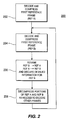
- FIG. 2 depicts a flow diagram 200 of the process of the present invention for decoding and compressing reference images to facilitate efficient memory utilization for the decoder 100 of FIG. 1.
- FIG. 2 depicts a flow diagram 200 of the process of the present invention for decoding and compressing reference images to facilitate efficient memory utilization for the decoder 100 of FIG. 1.
- an overview of the contents of an MPEG-like bitstream is presented.
- data representing the first anchor frame within a Group of Pictures (GOP) is intraframe encoded
- data representing the remaining frames is interframe encoded.
- GOP Group of Pictures
- the data representing intraframe encoded frames is generated by segmenting the pixel representing an image frame into respective 8x8 blocks and performing a discrete cosine transform (DCT) on the pixel data in each block.
- DCT discrete cosine transform
- data representing interframe encoded frames is generated by predicting image frames from preceding frames, following frames, or both; determining the differences between the predicted and actual frames; and performing the DCT on 8x8 blocks of residual data.
- the interframe DCT coefficients represent frame difference data.
- Motion vectors, for interframe encoded frames are code words which identify groups of 8x8 blocks of pixels in frames from which predictive frames are generated, which blocks must closely match the block currently being processed in the frame currently being encoded.
- the first frame in a GOP that can be decoded is an intraframe encoded frame (I frame) which is not motion compensated and as such the motion compensation processor applies zeros to the second input of the adder 108 of FIG. 1. Consequently, in step 202, the I frame data is decoded and applied to the input of the compressor/decompressor 114. As such, the I frame is compressed and stored in reference memory 120 as Reference A (i.e., the newest reference frame).
- Reference A i.e., the newest reference frame.
- an interframe encoded frame (P frame) that follows the I frame is decoded and compressed to form a second reference (for now Reference B).
- the first reference frame is renamed Reference B and the newest reference frame is Reference A.
- the newest reference frame that is decoded is always Reference A.
- the detailed information 122 that is stored when the new reference frame is decoded can be deleted or used for storing other information when the reference frame is renamed. That detailed information is not needed to decode other predicted frames, i.e., such detailed information is not necessary for decoding B frames of an MPEG compliant bitstream.
- the old reference frame can be recompressed and stored as Reference B.
- the remaining data within the video stream that lies between the intraframe encoded frames is decoded.
- all of the interframe encoded frames (B frames) are decoded using the two reference frames.
- the appropriate portion of a reference frame for the interframe encoded frame then being decoded is non-destructively recalled from frame memory and decompressed for use in motion compensation.
- the routine 200 When the next reference frame arrives, the routine 200 returns to step 204 to decode and compress that reference frame. It becomes the new reference frame such that the previously decoded frame becomes Reference B and the newly decoded reference frame becomes Reference A. Thereafter, these two frames are used to decode predicted frames and so on until the entire GOP is decoded.
- the routine 200 begins at step 202.
- the technique must be amenable to random access within the memory of regions of the reference frames.
- random access of 16x16 pixel blocks or 17x17 pixel blocks, if half-pel interpolation is used
- the reference image can be divided into regions, e.g., 16x16 blocks, and independently compressed region by region.
- the compression technique for each region can be either fixed length or variable length.
- a variable length coding technique is more efficient in terms of compression, the use of a fixed length coding technique is more amenable to a pointer system to facilitate random access of the regions.
- the regional compression could be made dependent upon neighboring regions; however, the additional compression efficiency is then traded against increased coding complexity.
- FIG. 3 depicts a memory structure 300 for a variable length encoded reference frame comprising a memory data space 320 and a pointer data space 310.
- the regions of the reference image have been variable length encoded and stored in the memory space 320 as segments of data, e.g., block 0 data, block 1 data, and so on to block N-1 data. Since these segments vary in length depending upon the content of the portion of the reference frame that they represent, the segments do not begin or end at any fixed memory location. As such, to facilitate retrieval of the regions for decompression and motion compensation, a number of pointers are needed that identify the storage locations of each segment.
- the memory address generator will first address the pointer memory space 310 to retrieve a pointer that identifies the address of the region corresponding to the desired region.
- the pointer memory space maps the regions to region locations within the memory space 320.
- Variable length coding techniques include wavelet-based, DCT-based, morphological coders, a standard single frame image compression technique such as JPEG, and the like. If a certain memory size limit is required, then a bit utilization control unit (bitrate controller) may be used to ensure that the number of bits used by the compression technique is within a bit budget defined by the memory.
- FIG. 4 depicts a memory structure 400 for a fixed length encoded reference frame comprising a memory data space 420.
- the regions of the reference image have been fixed length encoded and stored in the memory space 320 as segments of data, e.g., block 0 data, bloock 1 data, and so on to block N-1 data. Since these segments fixed in length, the segments begin and end at fixed memory locations relative to the first memory location (ADDR 1). As such, to facilitate retrieval of the regions for decompression and motion compensation, the memory address generator can merely address the known location of a particular segment of data without using a pointer memory.
- the particular address is computed by multiplying a region number (X) by the number of bytes in a segment (K) added to ADDR 1.
- the desired address is K*X+ADDR 1.
- the memory address generator computes the address and directly addresses the segment of the desired region.
- the memory structure of FIG. 4 may be used to store variable length coded reference frames by truncating the higher order bits of the encoded frame such that the encoded segments fit within the fixed length memory locations.
- the truncated information may be stored separately as the "detailed information" discussed above that is used to decode a new reference frame and deleted upon converting a reference frame from Reference A to Reference B.
- Block X-1 is coded with full precision, e.g., 8 bits, while the other images are coded as differences.
- image X-2 minus X-1 is coded
- X-3 minus X-1 is coded
- X-4 minus X-1 is coded using a logarithmic quantizer with 4 bits.
Description
- The invention relates to a predictive video decoder and, more particularly, to a method and apparatus for efficiently storing reference frames in a predictive video decoder.
- With the advent of digital video decoders being widely used in both consumer electronics and personal computers, these decoders must be fabricated in an inexpensive manner. Within predictive video decoders, such as MPEG (Moving Pictures Experts Group) compliant decoders, certain frames within the video sequence must be stored as reference frames since they are used to decode other frames within the video sequence. To store such reference frames (in MPEG terminology these frames are known as I and P frames) substantial amounts of memory are required to support the decoder functions. Presently MPEG decoders merely store an entire frame of decompressed pixelated video information as the reference images. These frames are subsequently used to decompress and predict other frames, e.g., so-called B frames, within the video sequence. Reducing the amount of memory required for storing such reference images would substantially reduce the overall cost of an MPEG decoder.
-
GB 2 310 101 - A need exists in the art for a method and apparatus to efficiently accomplish reference frame storage.
- Aspects of the invention are specified in the claims to which attention is invited.
- Specifically, the present invention stores one or more reference frames in a compressed format, then recalls and decompresses portions of the frames as needed to decode predicted frames within a received bitstream. At any point in time, under the MPEG standard, there are two reference frames that must be stored for use by the MPEG decoder. One of the frames (reference A) is used for producing a future reference frame, e.g., an I frame is used to predict a P frame and a P frame is used for producing another P frame. The other reference frame (Reference B) is not used for producing a future reference frame but is only used for producing one or more predicted frames, e.g.. B frames. To ensure an insignificant amount of distortion is produced within the decoded imagery, a lossless or high quality - compression technique should be used when compressing Reference A frames, while Reference B frames are compressed using a de-facto lossy compression technique. Such a de-facto lossy compression technique is used for compressing the Reference B frames because those frames are not used to predict reference frames and, as such, any errors generated in the decoded images are not accumulated. Note that in an MPEG-type system, where a previously decoded reference frame is used to predict the next reference frame as well as predicted frames, the invention decodes and stores the Reference A frame until it is used to decode another reference frame. Once the new reference frame is decoded, the new reference frame is deemed a Reference A frame and the previous reference A frame is renamed a Reference B frame. Additionally, upon renaming, the Reference B frame is further compressed using the de-facto lossy compression since it is no longer used to predict a reference frame. The invention decodes and replaces the Reference B frame every time a new reference frame is decoded.
- To implement the invention, additional circuitry is added to a conventional block-based video decoder. A conventional block-based video decoder contains a variable length decoder, an inverse quantizer, an inverse DCT unit, a summer, a video display memory, reference frame memory, and a motion compensation processor. The invention adds at least one compressor/decompressor as an input/output device coupled to the reference frame memory. If two reference frames are stored using different compression techniques, then one or two compressor/decompressors are used. Generally, the conventional decoder components operate as usual except that, as a reference frame is decoded, the frame is compressed within the compressor prior to storage in the reference frame memory. Thereafter, whenever a specific portion of the reference frame is needed for decoding another image, the portion is nondestructively recalled from memory, decompressed and coupled to the motion compensation processor for use in decoding images. By using this invention, a substantial amount of memory is saved for use by other processes or can be removed from the decoder all together.
- The teachings of the present invention can be readily understood by considering the following detailed description in conjunction with the accompanying drawings, in which:
- FIG. 1 depicts a block-based video decoder incorporating the present invention;
- FIG. 2 depicts a flow diagram representing the operation of the present invention;
- FIG. 3 depicts a memory structure used by the invention when a variable 20 length coding technique is used to compress a reference image;
- FIG. 4 depicts a memory structure used by the invention when a fixed length coding technique is used to compress a reference image.
- To facilitate understanding, identical reference numerals have been used, where possible, to designate identical elements that are common to the figures.
- FIG. 1 depicts an illustration of an
exemplary video decoder 100 arranged to process video data that is arranged in an MPEG-like format. Thisdecoder 100 is similar to a wide variety of known motion compensated predictive video decoders (block-based video decoders) and thus a detailed description regarding the conventional components of the decoder will not be provided herein. - A block-based encoded video signal (an MPEG compliant signal) is provided along a
path 124 to thevariable length decoder 102. The variable length decoder (VLD)102 performs variable length decoding as its main function, but also provides ancillary processing such as zigzag inverse processing, removes header information and other control data from the video stream, and extracts motion vector information that is coupled to amotion compensation processor 112. The VLD 102 also produces a plurality of blocks of quantized DCT data which is applied toinverse quantizer 104. The inverse quantized information is then applied to aninverse DCT unit 106. The IDCTunit 106 is responsive to the blocks of coefficients produced by the inverse quantizer and generates matrices (e.g., 8X8 arrays) of pixel information. The arrays are coupled, in predetermined order, to anadder 108. A second input to theadder 108 is supplied with motion compensated image information as described below. Output data from theadder 108 corresponds to decompressed, motion compensated pixel values. These values are input to a video display memory (VRAM) 110 where the pixels are accumulated until an entire frame of image information is assembled. Subsequently, the video signals that are accumulated within the video display RAM are ultimately applied to a display device, e.g., television screen or computer display. - Output signals from the
VLD 102 are also applied to amotion compensation processor 112 produces motion compensated blocks of video that are applied to the second input of theadder 108. To facilitate motion compensation, the reference frames (also known as anchor frames) within the video sequence must be stored to be used to motion compensate the various frames that are predicted within the video stream. Within an MPEG compliant stream, reference frames are interspersed with frames that are predicted from the reference frames, e.g., I and P frames are interspersed amongst B frames. As such, I and P frames must be stored as reference frames to facilitate decoding of the B frames. In addition, I frames and P frames are used to facilitate the decoding of P frames. - The present invention utilizes a compressor/
decompressor 114 as an input/output device for thereference frame memory 120. As such, reference frames must be compressed to be stored and portions of the compressed reference frame must be decompressed when used by themotion compensation processor 112 for prediction of other frames. Generally, an MPEG compliant decoder requires storing two reference frames at a time. Thus, the present invention uses a compressor/decompressor to compress and decompress a pair of reference frames. - Specifically, the
decoder 100 contains a frame compressor/decompressor 114 as well as two frame buffers (frame memory 116) for temporarily storing thereference frames decompressor 114 is coupled to the output ofadder 108. The compressor/decompressor 114 is coupled toreference memory 116 as well as to themotion compensation processor 112 - The invention uses a single compressor/
decompressor 114 to process a Reference A frame and store all frame information very accurately, e.g., using a highly accurate, lossless compression technique. However, when a new reference frame is decoded and Reference A frame is renamed as a Reference B frame, the memory space used to storedetailed information 122 about the image in the reference frame, e.g., high frequency pixel data, can be ignored such that those memory location for detailed information can be used to store other information. This produces de facto lossy compression for the Reference B frame. Consequently, less overall memory is used to store two frames of reference imagery and the loss of the detailed information does not substantially impact the decoding of predicted frames such as B-frames in an MPEG compliant bitstream. Anaddress generator 128 provides the addresses for recalling the appropriate portions of the compressed frames for decompression. As such, this generator, in effect, renames the reference frames by recalling the appropriate information when needed. Although FIG. 1 depicts a single reference memory, a pair of memories may be used as separate frame buffers. Additionally, although a single compressor/decompressor is shown and described, a pair of compressor/decompressors may be used to separately handle compression and decompression of each reference image. Such individual compressor/decompressors would enable the decoder to utilize different compression techniques for compressing each type of reference frame. As such, to rename the reference frames and use a lossy compression technique for Reference B, Reference A would be recalled, decompressed and then recompressed using a lossy compression technique. The recompressed Reference A (old reference) would be stored as Reference B. FIG. 2 depicts a flow diagram 200 of the process of the present invention for decoding and compressing reference images to facilitate efficient memory utilization for thedecoder 100 of FIG. 1. To best understand the operation of the present invention, an overview of the contents of an MPEG-like bitstream is presented. In general, in an MPEG-like bitstream, data representing the first anchor frame within a Group of Pictures (GOP) is intraframe encoded, and data representing the remaining frames is interframe encoded. The data representing intraframe encoded frames is generated by segmenting the pixel representing an image frame into respective 8x8 blocks and performing a discrete cosine transform (DCT) on the pixel data in each block. No motion vectors are generated for the first intraframe encoded frame, i.e., the intraframe information is not motion compensated in an I frame. - Alternatively, data representing interframe encoded frames is generated by predicting image frames from preceding frames, following frames, or both; determining the differences between the predicted and actual frames; and performing the DCT on 8x8 blocks of residual data. The interframe DCT coefficients represent frame difference data. Motion vectors, for interframe encoded frames are code words which identify groups of 8x8 blocks of pixels in frames from which predictive frames are generated, which blocks must closely match the block currently being processed in the frame currently being encoded.
- Generally the first frame in a GOP that can be decoded is an intraframe encoded frame (I frame) which is not motion compensated and as such the motion compensation processor applies zeros to the second input of the
adder 108 of FIG. 1. Consequently, instep 202, the I frame data is decoded and applied to the input of the compressor/decompressor 114. As such, the I frame is compressed and stored inreference memory 120 as Reference A (i.e., the newest reference frame). Atstep 204, the next reference frame, an interframe encoded frame (P frame)that follows the I frame is decoded and compressed to form a second reference (for now Reference B). Since the second reference frame (P frame) is now the newest reference frame, atstep 206, the first reference frame is renamed Reference B and the newest reference frame is Reference A. As such, using this routine, the newest reference frame that is decoded is always Reference A. Additionally, if additional memory is to be saved, thedetailed information 122 that is stored when the new reference frame is decoded can be deleted or used for storing other information when the reference frame is renamed. That detailed information is not needed to decode other predicted frames, i.e., such detailed information is not necessary for decoding B frames of an MPEG compliant bitstream. Alternatively, if two compression techniques are used, at the renamingstep 206, the old reference frame can be recompressed and stored as Reference B. - Using these two reference frames, at
step 208, the remaining data within the video stream that lies between the intraframe encoded frames is decoded. As such all of the interframe encoded frames (B frames) are decoded using the two reference frames. To facilitate decoding, the appropriate portion of a reference frame for the interframe encoded frame then being decoded is non-destructively recalled from frame memory and decompressed for use in motion compensation. - When the next reference frame arrives, the routine 200 returns to step 204 to decode and compress that reference frame. It becomes the new reference frame such that the previously decoded frame becomes Reference B and the newly decoded reference frame becomes Reference A. Thereafter, these two frames are used to decode predicted frames and so on until the entire GOP is decoded. When each new I frame is identified, the routine 200 begins at
step 202. - Various forms of compression and decompression can be used in conjunction with the present invention. However, it should be noted that the technique must be amenable to random access within the memory of regions of the reference frames. In an MPEG compliant system, random access of 16x16 pixel blocks (or 17x17 pixel blocks, if half-pel interpolation is used) must be available. To facilitate such access and decompression of regions of the reference image, the reference image can be divided into regions, e.g., 16x16 blocks, and independently compressed region by region. The compression technique for each region can be either fixed length or variable length. A variable length coding technique is more efficient in terms of compression, the use of a fixed length coding technique is more amenable to a pointer system to facilitate random access of the regions. To further enhance compression, the regional compression could be made dependent upon neighboring regions; however, the additional compression efficiency is then traded against increased coding complexity.
- FIG. 3 depicts a
memory structure 300 for a variable length encoded reference frame comprising amemory data space 320 and apointer data space 310. To use a variable length coding technique, the regions of the reference image have been variable length encoded and stored in thememory space 320 as segments of data, e.g., block 0 data, block 1 data, and so on to block N-1 data. Since these segments vary in length depending upon the content of the portion of the reference frame that they represent, the segments do not begin or end at any fixed memory location. As such, to facilitate retrieval of the regions for decompression and motion compensation, a number of pointers are needed that identify the storage locations of each segment. As such, when a particular region is required, the memory address generator will first address thepointer memory space 310 to retrieve a pointer that identifies the address of the region corresponding to the desired region. As such, the pointer memory space maps the regions to region locations within thememory space 320. Variable length coding techniques include wavelet-based, DCT-based, morphological coders, a standard single frame image compression technique such as JPEG, and the like. If a certain memory size limit is required, then a bit utilization control unit (bitrate controller) may be used to ensure that the number of bits used by the compression technique is within a bit budget defined by the memory. - FIG. 4 depicts a
memory structure 400 for a fixed length encoded reference frame comprising amemory data space 420. To use a fixed length coding technique, the regions of the reference image have been fixed length encoded and stored in thememory space 320 as segments of data, e.g., block 0 data,bloock 1 data, and so on to block N-1 data. Since these segments fixed in length, the segments begin and end at fixed memory locations relative to the first memory location (ADDR 1). As such, to facilitate retrieval of the regions for decompression and motion compensation, the memory address generator can merely address the known location of a particular segment of data without using a pointer memory. The particular address is computed by multiplying a region number (X) by the number of bytes in a segment (K) added toADDR 1. Mathematically, the desired address is K*X+ADDR 1. As such, when a particular region is required, the memory address generator computes the address and directly addresses the segment of the desired region. - The memory structure of FIG. 4 may be used to store variable length coded reference frames by truncating the higher order bits of the encoded frame such that the encoded segments fit within the fixed length memory locations. The truncated information may be stored separately as the "detailed information" discussed above that is used to decode a new reference frame and deleted upon converting a reference frame from Reference A to Reference B.
- As a simple example of a fixed length compression technique that can be used to compress the reference frames, a group of decoded samples are arranged in 2x2 blocks identified as blocks X-1, X-2, X-3 and X-4. Block X-1 is coded with full precision, e.g., 8 bits, while the other images are coded as differences. As such, image X-2 minus X-1 is coded, X-3 minus X-1 is coded, and X-4 minus X-1 is coded using a logarithmic quantizer with 4 bits. Using this simple compression scheme, the memory savings is as much as 37% over that of storing full precision blocks. This technique introduces little distortion and provides a pre-defined addressing technique due to the constant length code words.
- Although various embodiments which incorporate the teachings of the present invention have been shown and described in detail herein, those skilled in the art can readily devise many other varied embodiments that still incorporate these teachings.
Claims (8)
- A method of decoding block-based video, the method utilizing reference frames contained in a bitstream of encoded video information and comprising the steps of:(a) decoding a reference frame from said bitstream and compressing said reference frame with a lossless compression technique to produce compressed reference frame data and storing said compressed reference frame data.(b) decoding a next reference frame from said bitstream and compressing said reference frame with said lossless compression technique to produce second compressed reference frame data storing said compressed reference frame data and deleting part of the previous reference frame data;(c) selectively decompressing (208) portions of said first and/or second compressed reference frame data to decode other frames in said bitstream;(d) upon decoding a next reference frame from said bitstream, replacing the oldest stored compressed reference frame data with compressed reference frame data corresponding to said new reference frame and, upon replacing said oldest stored compressed reference frame data, deleting part of the oldest remaining stored compressed reference frame data; and(e) repeating steps (c) and (d).
- The method of claim 1 wherein the compressing steps further comprise the steps of:dividing a reference image into regions;compressing each region separately; andstoring said compressed regions.
- The method of claim 1, wherein said lossless compression technique comprises producing variable-length compressed reference frame data.
- The method of claim 3, wherein said deleting step comprises truncating said variable-length compressed reference frame data to a fixed length.
- The method of claim 4, wherein said truncating step comprises deleting data corresponding to detailed image data.
- The method of claim 1, wherein said lossless compression technique comprises wavelet compression.
- A video decoder for decoding a bitstream containing video information comprising:a reference frame decoder (102-108, 112);a compression-decompression means (114) coupled to said reference frame decoder, for compressing and decompressing reference frames with a lossless compression technique to produce compressed reference frame data; andmemory means (116) coupled to said compressor/compressor, for storing compressed reference frame data corresponding to two most recent reference frames until portions of said reference frames are needed for decoding other frames; wherein the decoder is arranged to upon decoding a next reference frame from said bitstream, replace (206) an oldest compressed reference frame data of said compressed reference frame data corresponding to two most recent reference frames with compressed reference frame data corresponding to said new reference frame, and, upon replacing said oldest compressed reference frame data, delete part of the oldest renciting compressed reference frame data.
- The video decoder of claim 7 comprising:a first compressor/decompressor (114) coupled to said reference frame decoder, for compressing and decompressing reference frames;a first memory coupled to said first compressor/decompressor, for storing said compressed reference frames until portions of said reference frames are needed for decoding other frames;a second compressor/decompressor; coupled to said reference frame decoder for compressing and decompressing reference frames; anda second memory, coupled to said second compressor/decompressor, for storing said compressed reference frames until said reference frames are needed for decoding other frames.
Applications Claiming Priority (5)
| Application Number | Priority Date | Filing Date | Title |
|---|---|---|---|
| US6011297P | 1997-09-26 | 1997-09-26 | |
| US60112P | 1997-09-26 | ||
| US09/001,201 US5933195A (en) | 1997-09-26 | 1997-12-30 | Method and apparatus memory requirements for storing reference frames in a video decoder |
| US1201 | 1997-12-30 | ||
| PCT/US1998/020314 WO1999016253A1 (en) | 1997-09-26 | 1998-09-28 | Method and apparatus for reducing memory requirements for storing reference frames in a video decoder |
Publications (3)
| Publication Number | Publication Date |
|---|---|
| EP1025709A1 EP1025709A1 (en) | 2000-08-09 |
| EP1025709A4 EP1025709A4 (en) | 2001-05-02 |
| EP1025709B1 true EP1025709B1 (en) | 2007-11-14 |
Family
ID=26668707
Family Applications (1)
| Application Number | Title | Priority Date | Filing Date |
|---|---|---|---|
| EP98949587A Expired - Lifetime EP1025709B1 (en) | 1997-09-26 | 1998-09-28 | Method and apparatus for reducing memory requirements for storing reference frames in a video decoder |
Country Status (8)
| Country | Link |
|---|---|
| US (1) | US5933195A (en) |
| EP (1) | EP1025709B1 (en) |
| JP (1) | JP2001517906A (en) |
| KR (1) | KR100635687B1 (en) |
| CN (1) | CN1147162C (en) |
| AU (1) | AU9588198A (en) |
| DE (1) | DE69838729T2 (en) |
| WO (1) | WO1999016253A1 (en) |
Families Citing this family (29)
| Publication number | Priority date | Publication date | Assignee | Title |
|---|---|---|---|---|
| US6594315B1 (en) * | 1996-12-18 | 2003-07-15 | Thomson Licensing S.A. | Formatting of recompressed data in an MPEG decoder |
| JPH10276349A (en) * | 1997-03-27 | 1998-10-13 | Asahi Optical Co Ltd | Image signal correction device |
| US6081802A (en) * | 1997-08-12 | 2000-06-27 | Microsoft Corporation | System and method for accessing compactly stored map element information from memory |
| US6295094B1 (en) * | 1997-09-11 | 2001-09-25 | U.S. Philips Corporation | Instant replay of digital video optimized using non MPEG frame tags |
| US6499060B1 (en) | 1999-03-12 | 2002-12-24 | Microsoft Corporation | Media coding for loss recovery with remotely predicted data units |
| JP3322233B2 (en) * | 1999-03-19 | 2002-09-09 | 日本電気株式会社 | Moving image decompression method and recording medium recording program for executing the method |
| US6615335B1 (en) * | 1999-07-02 | 2003-09-02 | Koninklijke Philips Electronics N.V. | Compressed storage of information |
| KR100335057B1 (en) * | 2000-03-08 | 2002-05-02 | 구자홍 | Apparatus for receiving moving picture |
| EP1269761A1 (en) * | 2000-03-31 | 2003-01-02 | Koninklijke Philips Electronics N.V. | Encoding of two correlated sequences of data |
| US6864896B2 (en) * | 2001-05-15 | 2005-03-08 | Rambus Inc. | Scalable unified memory architecture |
| US6937652B2 (en) * | 2002-04-19 | 2005-08-30 | Seiko Epson Corporation | Frame compression using radix approximation |
| CN1666532A (en) * | 2002-07-02 | 2005-09-07 | 松下电器产业株式会社 | Image encoding method and image decoding method |
| KR101132351B1 (en) * | 2004-05-03 | 2012-04-05 | 톰슨 리서치 펀딩 코포레이션 | Method and apparatus enabling fast channel change for dsl system |
| WO2006027846A1 (en) * | 2004-09-10 | 2006-03-16 | Matsushita Electric Industrial Co., Ltd. | Zapping stream generating apparatus and method |
| US8634413B2 (en) | 2004-12-30 | 2014-01-21 | Microsoft Corporation | Use of frame caching to improve packet loss recovery |
| US7965771B2 (en) | 2006-02-27 | 2011-06-21 | Cisco Technology, Inc. | Method and apparatus for immediate display of multicast IPTV over a bandwidth constrained network |
| US8218654B2 (en) * | 2006-03-08 | 2012-07-10 | Cisco Technology, Inc. | Method for reducing channel change startup delays for multicast digital video streams |
| US8031701B2 (en) * | 2006-09-11 | 2011-10-04 | Cisco Technology, Inc. | Retransmission-based stream repair and stream join |
| US7937531B2 (en) * | 2007-02-01 | 2011-05-03 | Cisco Technology, Inc. | Regularly occurring write back scheme for cache soft error reduction |
| US8769591B2 (en) | 2007-02-12 | 2014-07-01 | Cisco Technology, Inc. | Fast channel change on a bandwidth constrained network |
| US7940644B2 (en) * | 2007-03-14 | 2011-05-10 | Cisco Technology, Inc. | Unified transmission scheme for media stream redundancy |
| US20080253369A1 (en) * | 2007-04-16 | 2008-10-16 | Cisco Technology, Inc. | Monitoring and correcting upstream packet loss |
| US8787153B2 (en) | 2008-02-10 | 2014-07-22 | Cisco Technology, Inc. | Forward error correction based data recovery with path diversity |
| US20100098166A1 (en) * | 2008-10-17 | 2010-04-22 | Texas Instruments Incorporated | Video coding with compressed reference frames |
| US9168946B2 (en) * | 2010-03-19 | 2015-10-27 | Javad Gnss, Inc. | Method for generating offset paths for ground vehicles |
| WO2012095490A1 (en) * | 2011-01-12 | 2012-07-19 | Siemens Aktiengesellschaft | Compression and decompression of reference images in a video encoder |
| US20130243100A1 (en) | 2012-03-15 | 2013-09-19 | Mediatek Inc. | System and Method for Adaptive Frame Re-compression in Video Processing System |
| US20140169467A1 (en) * | 2012-12-14 | 2014-06-19 | Ce Wang | Video coding including shared motion estimation between multple independent coding streams |
| US11244476B2 (en) * | 2020-04-06 | 2022-02-08 | Samsung Display Co., Ltd. | Systems and methods for low-complexity near lossless fixed-rate hybrid data compression codecs |
Family Cites Families (5)
| Publication number | Priority date | Publication date | Assignee | Title |
|---|---|---|---|---|
| US5262854A (en) * | 1992-02-21 | 1993-11-16 | Rca Thomson Licensing Corporation | Lower resolution HDTV receivers |
| US5614952A (en) * | 1994-10-11 | 1997-03-25 | Hitachi America, Ltd. | Digital video decoder for decoding digital high definition and/or digital standard definition television signals |
| US5644361A (en) * | 1994-11-30 | 1997-07-01 | National Semiconductor Corporation | Subsampled frame storage technique for reduced memory size |
| US6968003B1 (en) * | 1996-01-29 | 2005-11-22 | International Business Machines Corporation | Speed-memory tradeoff for MPEG decoders |
| US5777677A (en) * | 1996-02-09 | 1998-07-07 | International Business Machines Corporation | Approximate MPEG decoder with compressed reference frames |
-
1997
- 1997-12-30 US US09/001,201 patent/US5933195A/en not_active Expired - Lifetime
-
1998
- 1998-09-28 KR KR1020007003230A patent/KR100635687B1/en not_active IP Right Cessation
- 1998-09-28 CN CNB988095289A patent/CN1147162C/en not_active Expired - Lifetime
- 1998-09-28 AU AU95881/98A patent/AU9588198A/en not_active Abandoned
- 1998-09-28 JP JP2000513414A patent/JP2001517906A/en active Pending
- 1998-09-28 EP EP98949587A patent/EP1025709B1/en not_active Expired - Lifetime
- 1998-09-28 WO PCT/US1998/020314 patent/WO1999016253A1/en active IP Right Grant
- 1998-09-28 DE DE69838729T patent/DE69838729T2/en not_active Expired - Lifetime
Also Published As
| Publication number | Publication date |
|---|---|
| US5933195A (en) | 1999-08-03 |
| CN1299562A (en) | 2001-06-13 |
| AU9588198A (en) | 1999-04-12 |
| EP1025709A4 (en) | 2001-05-02 |
| DE69838729D1 (en) | 2007-12-27 |
| KR100635687B1 (en) | 2006-10-17 |
| WO1999016253A1 (en) | 1999-04-01 |
| EP1025709A1 (en) | 2000-08-09 |
| CN1147162C (en) | 2004-04-21 |
| KR20010030721A (en) | 2001-04-16 |
| DE69838729T2 (en) | 2008-10-30 |
| JP2001517906A (en) | 2001-10-09 |
Similar Documents
| Publication | Publication Date | Title |
|---|---|---|
| EP1025709B1 (en) | Method and apparatus for reducing memory requirements for storing reference frames in a video decoder | |
| KR100253931B1 (en) | Approximate mpeg decoder with compressed reference frames | |
| US6704358B1 (en) | Method and apparatus for resizing image information | |
| US6222886B1 (en) | Compression based reduced memory video decoder | |
| EP1446953B1 (en) | Multiple channel video transcoding | |
| EP3386199B1 (en) | Lossless compression method and system appled to video hard decoding | |
| EP0580454A2 (en) | Coding and decoding of digital data | |
| CA2151023A1 (en) | Method of coding/decoding of a data stream | |
| JPH118849A (en) | Picture encoding method and device therefor | |
| US6298087B1 (en) | System and method for decoding a variable length code digital signal | |
| KR101066051B1 (en) | Apparatus and method for multiple description encoding | |
| US6163576A (en) | Video encoder having reduced memory bandwidth requirements | |
| JPH08116539A (en) | Dynamic image coder and dynamic image coding method | |
| JP2004356850A (en) | Expanding apparatus for compressed moving picture and image display apparatus employing the same | |
| JP2004356851A (en) | Compression apparatus for moving picture and imaging apparatus employing the same | |
| JPH1098731A (en) | Device and method for decoding digital image | |
| WO2002073973A2 (en) | Method and apparatus for temporal wavelet compression | |
| US6016365A (en) | Decoder having adaptive function of eliminating block effect | |
| US20110249959A1 (en) | Video storing method and device based on variable bit allocation and related video encoding and decoding apparatuses | |
| KR20010018656A (en) | Apparatus for receiving moving picture | |
| KR100598093B1 (en) | Apparatus and method with low memory bandwidth for video data compression | |
| KR20020026189A (en) | Efficient video data access using fixed ratio compression | |
| US6574275B1 (en) | Decoding apparatus and decoding method | |
| US7675972B1 (en) | System and method for multiple channel video transcoding | |
| JPH0487460A (en) | Picture processor |
Legal Events
| Date | Code | Title | Description |
|---|---|---|---|
| PUAI | Public reference made under article 153(3) epc to a published international application that has entered the european phase |
Free format text: ORIGINAL CODE: 0009012 |
|
| 17P | Request for examination filed |
Effective date: 20000327 |
|
| AK | Designated contracting states |
Kind code of ref document: A1 Designated state(s): DE FR GB IE IT NL |
|
| RIN1 | Information on inventor provided before grant (corrected) |
Inventor name: FLORENCIO, DINEI |
|
| A4 | Supplementary search report drawn up and despatched |
Effective date: 20010322 |
|
| AK | Designated contracting states |
Kind code of ref document: A4 Designated state(s): DE FR GB IE IT NL |
|
| 17Q | First examination report despatched |
Effective date: 20040312 |
|
| REG | Reference to a national code |
Ref country code: NL Ref legal event code: ZD Free format text: PAT. BUL. 05/2005, HEADING PD, SECTION 4, PAGE 793, PATENT NUMBER 1025709, INT. CL. C07D277/64; THE TITLE SHOULD READ: 3- (1- /C3- (1, 3- BENZOTHIAZOOL-6-YL) PROPYLCARBAMOYL! CYCLOALKYL) PROPAANZUURDERIVATEN ALS NEP-REMMERS. |
|
| RAP1 | Party data changed (applicant data changed or rights of an application transferred) |
Owner name: MEDIATEK INC. |
|
| GRAP | Despatch of communication of intention to grant a patent |
Free format text: ORIGINAL CODE: EPIDOSNIGR1 |
|
| RIN1 | Information on inventor provided before grant (corrected) |
Inventor name: FLORENCIO, DINEI |
|
| GRAS | Grant fee paid |
Free format text: ORIGINAL CODE: EPIDOSNIGR3 |
|
| GRAA | (expected) grant |
Free format text: ORIGINAL CODE: 0009210 |
|
| AK | Designated contracting states |
Kind code of ref document: B1 Designated state(s): DE FR GB IE IT NL |
|
| REG | Reference to a national code |
Ref country code: GB Ref legal event code: FG4D |
|
| REG | Reference to a national code |
Ref country code: IE Ref legal event code: FG4D |
|
| REF | Corresponds to: |
Ref document number: 69838729 Country of ref document: DE Date of ref document: 20071227 Kind code of ref document: P |
|
| PG25 | Lapsed in a contracting state [announced via postgrant information from national office to epo] |
Ref country code: NL Free format text: LAPSE BECAUSE OF FAILURE TO SUBMIT A TRANSLATION OF THE DESCRIPTION OR TO PAY THE FEE WITHIN THE PRESCRIBED TIME-LIMIT Effective date: 20071114 |
|
| NLV1 | Nl: lapsed or annulled due to failure to fulfill the requirements of art. 29p and 29m of the patents act | ||
| ET | Fr: translation filed | ||
| PLBE | No opposition filed within time limit |
Free format text: ORIGINAL CODE: 0009261 |
|
| STAA | Information on the status of an ep patent application or granted ep patent |
Free format text: STATUS: NO OPPOSITION FILED WITHIN TIME LIMIT |
|
| 26N | No opposition filed |
Effective date: 20080815 |
|
| PG25 | Lapsed in a contracting state [announced via postgrant information from national office to epo] |
Ref country code: IE Free format text: LAPSE BECAUSE OF NON-PAYMENT OF DUE FEES Effective date: 20080929 |
|
| PG25 | Lapsed in a contracting state [announced via postgrant information from national office to epo] |
Ref country code: IT Free format text: LAPSE BECAUSE OF NON-PAYMENT OF DUE FEES Effective date: 20080930 |
|
| REG | Reference to a national code |
Ref country code: FR Ref legal event code: PLFP Year of fee payment: 19 |
|
| REG | Reference to a national code |
Ref country code: FR Ref legal event code: PLFP Year of fee payment: 20 |
|
| PGFP | Annual fee paid to national office [announced via postgrant information from national office to epo] |
Ref country code: GB Payment date: 20170927 Year of fee payment: 20 Ref country code: FR Payment date: 20170925 Year of fee payment: 20 |
|
| PGFP | Annual fee paid to national office [announced via postgrant information from national office to epo] |
Ref country code: DE Payment date: 20170927 Year of fee payment: 20 |
|
| REG | Reference to a national code |
Ref country code: DE Ref legal event code: R071 Ref document number: 69838729 Country of ref document: DE |
|
| REG | Reference to a national code |
Ref country code: GB Ref legal event code: PE20 Expiry date: 20180927 |
|
| PG25 | Lapsed in a contracting state [announced via postgrant information from national office to epo] |
Ref country code: GB Free format text: LAPSE BECAUSE OF EXPIRATION OF PROTECTION Effective date: 20180927 |