EP1024608A2 - Method for diversity reception of a cdma signal and corresponding transmitter - Google Patents
Method for diversity reception of a cdma signal and corresponding transmitter Download PDFInfo
- Publication number
- EP1024608A2 EP1024608A2 EP00400058A EP00400058A EP1024608A2 EP 1024608 A2 EP1024608 A2 EP 1024608A2 EP 00400058 A EP00400058 A EP 00400058A EP 00400058 A EP00400058 A EP 00400058A EP 1024608 A2 EP1024608 A2 EP 1024608A2
- Authority
- EP
- European Patent Office
- Prior art keywords
- coefficients
- unit
- channel
- transfer function
- represent
- Prior art date
- Legal status (The legal status is an assumption and is not a legal conclusion. Google has not performed a legal analysis and makes no representation as to the accuracy of the status listed.)
- Withdrawn
Links
Images


Classifications
-
- H—ELECTRICITY
- H04—ELECTRIC COMMUNICATION TECHNIQUE
- H04B—TRANSMISSION
- H04B7/00—Radio transmission systems, i.e. using radiation field
- H04B7/02—Diversity systems; Multi-antenna system, i.e. transmission or reception using multiple antennas
- H04B7/04—Diversity systems; Multi-antenna system, i.e. transmission or reception using multiple antennas using two or more spaced independent antennas
- H04B7/08—Diversity systems; Multi-antenna system, i.e. transmission or reception using multiple antennas using two or more spaced independent antennas at the receiving station
- H04B7/0837—Diversity systems; Multi-antenna system, i.e. transmission or reception using multiple antennas using two or more spaced independent antennas at the receiving station using pre-detection combining
- H04B7/0842—Weighted combining
- H04B7/0845—Weighted combining per branch equalization, e.g. by an FIR-filter or RAKE receiver per antenna branch
Definitions
- the present invention refers to a code division multiple access (CDMA) system with diversity reception. More specifically, the invention proposes a method for diversity reception of a CDMA signal as well as a transmission unit for sending a CDMA signal from said first unit to a second unit in a code division multiple access telecommunications system.
- CDMA code division multiple access
- a CDMA diversity receiver typically comprises an acquisition circuit 10 , a despreader circuit 11 and a combiner circuit 12 .
- the acquisition circuit 10 typically comprises a correlator circuit that correlates the received signal with different PN sequences. These different PN sequences correspond to a single PN signal with different phases, respectively.
- the despreader circuit 11 multiplies the signal received with each of N PN codes with respective phases, said N PN codes being those which produce correlation peaks.
- the N outputs of the despreader circuit 11 are applied to the combiner circuit 12 , which adds the N signals produced by the despreader circuit 11 .
- the N signals received in diversity reception are combined.
- the present invention proposes the division of this number of operations by N, providing a method and a device for diversity reception of a CDMA signal.
- the invention is particularly applicable in a limited mobility environment in which the diversity paths of a single signal change at slow speed.
- Another object of the present invention is to provide a solution within the framework of a radiocommunications system which works in frequency duplex mode, whereby two respective different frequencies are used for transmitting data from a terminal to a base station and for transmitting data from the base station to the terminal.
- a method for diversity reception by a second unit of a CDMA signal transmitted by a first unit in a code division multiple access system is characterised by the predistortion applied in the first unit to said signal prior to its transmission, the predistortion applied to the signal having an effect appreciably opposite to the effect produced by a first channel over which the first unit sends data to said second unit.
- the first unit sends data to the second unit over the first channel and the second unit sends data to said first unit over a second channel, the method comprising the steps of:
- the coefficients that represent the second channel are the inverse transfer function coefficients of the second channel and the coefficients that represent the first and second channels together are the direct transfer function coefficients of the first and second channels together, said predistortion being performed with the inverse coefficients of the convolution of the inverse transfer function coefficients of the second channel and of the direct transfer function coefficients of the first and second channels together.
- the coefficients that represent the second channel are the direct transfer function coefficients of the second channel and the coefficients that represent the first and second channels together are the inverse transfer function coefficients of the first and second channels together, said predistortion being performed with the inverse coefficients of the convolution of the direct transfer function coefficients of the second channel and of the inverse transfer function coefficients of the first and second channels together.
- the first unit sends data to said second unit over the first channel and said second unit sends data to said first unit over a second channel, the method comprising the steps of:
- the coefficients that represent the second channel are the inverse transfer function coefficients of the second channel and the coefficients that represent the first channel are the inverse coefficients of the convolution of said backward sequence received by the first unit and of a predetermined inverse sequence.
- the present invention also provides a unit of a telecommunications system for transmitting a signal to a remote unit over a first channel.
- the unit comprises a circuit for multiplying the signal to be sent by a CDMA code that is in the form of a CDMA code sequence, and is characterised in that it comprises a predistorter circuit, for predistorting said signal to be sent by applying to said signal an effect appreciably opposite to the effect produced by the transmission channel.
- the unit can comprise:
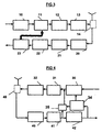
- FIG. 2 shows two units U1 and U2 of a CDMA telecommunications system exchanging data over two channels H1 and H2 , respectively.
- the invention is described in the present application within the frame of a radiocommunications system for the subscriber local loop although said invention can be applied in all types of application employing diversity reception.
- the two radio channels H1 and H2 are defined by two frequencies equal to each other in a Time Division Duplex (TDD) application, or different from each other in a Frequency Division Duplex (FDD) application.
- TDD Time Division Duplex
- FDD Frequency Division Duplex
- the invention is applicable in these two implementations but the following description refers to a preferred embodiment within the framework of a Frequency Division Duplex (FDD) application.
- the first unit U1 comprises, in the transmission direction, a baseband CDMA modulator 10 , a predistorter circuit 11 , an uplink converter 12 , a transmission amplifier 13 and a duplexer 14 .
- Various embodiments of a CDMA modulator 10 are known from the state of the art and this circuit 10 is not described in detail in the present application.
- the first unit U1 comprises said duplexer 14 , a reception amplifier 20 , a downlink converter 21 , a baseband CDMA demodulator 22 and a generator of predistortion coefficients 23 .
- Various embodiments of a CDMA demodulator 22 are known from the state of the art and this circuit 22 is not described in detail.
- figure 1.2 shows a schematic representation of a baseband CDMA modulator 10 and its associated uplink converter 12 as well as a downlink converter 21 and its associated baseband demodulator 22 .
- FIG. 5 shows a predistorter circuit 11 of length N according to an embodiment of the present invention.
- This predistorter circuit has the configuration of a conventional linear equaliser, but any other type of predistorter circuit can be employed according to the invention.
- the predistorter circuit 11 comprises taps, spaced at time intervals of T/2, where T is the minimum separation between two successive symbols of the CDMA code, for example PN.
- the signal x(n) produced by the modulator 10 is applied to an input of the predistorter circuit which delays said signal through T/2 delay lines connected in cascade.
- the output of the first delay line is x(n-1), the output of the second delay line is x(n-2), the output of the third delay line is x(n-3), and so on repeatedly such that the output of the final delay line is x( n-N+1 ).
- the N predistortion coefficients c0, c1, c2, ..., cN-1 are complex numbers.
- Multiplier circuits multiply the signal x(n) and the different delayed signals x(n-1), x(n-2), x(n-3), ..., x( n-N+1 ) by the predistortion coefficients c0, c1, c2, ..., cN-1 , respectively.
- An adder circuit totals the resulting multiplied signals in order to produce the predistorted signal which is applied to an input of the uplink converter 12 .
- the predistortion coefficients c0, c1, c2, ..., cN-1 change periodically according to the algorithms of figures 7 and 8 to adapt to the characteristics of the channel H1 .
- the generator of predistortion coefficients 23 shown in figure 6 comprises a translator 230 , a frequency response generator 231 , an inverse translator 232 , a distributing circuit of predistortion coefficients 234 and, alternatively, a selector of coefficients 233 .
- the output of the distributing circuit of predistortion coefficients 234 applies the appropriate predistortion coefficients c0, c1, c2, ..., cN-1 to the predistorter circuit 11 .
- the generator of predistortion coefficients 23 may employ a processor, a microprocessor or another signal processing device.
- a training signal, or sequence, received from the output of demodulator 22 ( Figure 3) and sampled by a sampler circuit (not shown) is applied to an input of the generator of predistortion coefficients 23 .
- the sampled signal is received by the translator 230 that converts the time domain signal received into an equivalent signal in the frequency domain.
- a DFT Discrete Fourier Transform
- the resulting signal is applied to an input of the frequency response generator, or channel inverter 231 , which applies the following existing linear relationships for generating the inverse transfer function coefficients: a received training signal divided by a training signal as it is really, is the direct transfer function of the channel; and the inverse of this transfer function corresponds to the division of the training signal as it really is by the received training signal.
- inverse transfer function coefficients refers to coefficients that, in the time domain, when subjected to convolution with the direct transfer function coefficients (i.e. the coefficients that define the channel) give as a result the Dirac pulse, and, in the frequency domain, when multiplied by the direct transfer function coefficients, give as a result the Fourier transform of this pulse.
- these inverse transfer function coefficients are the coefficients of the inverse channel.
- the training signal received by unit U1 is normally different from the training signal initially transmitted, and corresponds to a distorted version of said transmitted signal.
- the training signal as it really is, is stored locally in the frequency response generator 231 .
- the inverse translator 232 generates a time domain pulse response sequence ⁇ y(0), y(1), y(2), ..., y(M-1) ⁇ of the inverse channel.
- This time domain pulse response represents the inverse transfer function characteristics of a channel in the time domain, and defines a finite pulse response characteristic of said channel.
- the overall pulse frequency response is equivalent to a band-pass filter with a pass-band equal to the pass-band of the channel.
- the pulse response sequence ⁇ y(0), y(1), y(2), ..., y(M-1) ⁇ defines predistortion coefficients employed by the distributing circuit of predistortion coefficients 234 to supply the coefficients of the predistorter circuit of figure 5, as is described below with reference to figures 7 and 8.
- M is equal to N.
- the predistorter circuit 11 can use fewer coefficients (N coefficients) than the M coefficients ⁇ y(0), y(1), y(2), etc, y(M-1) ⁇ produced by the inverse translator 232 . Consequently, the selector 233 selects, for example, the coefficients associated with a power peak in the received signal. These selected coefficients are applied to the distributing circuit of predistortion coefficients 234 for defining the predistortion coefficients for the signal to be transmitted by unit U1 .
- An embodiment of a generator of predistortion coefficients 23 is described in the document US-A-5636244 starting in line 14 of column 5, incorporated in the present patent application by reference.
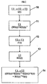
- Figure 7 shows a first alternative of the present invention.
- the first unit U1 sends a first predetermined sequence, or training sequence, s(t) , to the second unit U2 that forwards it exactly as received to the first unit U1 , in the form of a backward sequence.
- the second unit U2 comprises, in the transmission direction, a baseband CDMA modulator 30 , an uplink converter 31 , a transmission amplifier 32 and a duplexer 45 .
- this second unit U2 comprises the duplexer 45 , a reception amplifier 40 , a downlink converter 41 and a baseband CDMA demodulator 42 .
- the baseband CDMA demodulator 42 comprises, in cascade, a correlating device and a despreader circuit 11 , and does not include a combiner circuit 12 and an acquisition circuit 10 as complex as that of figure 1.
- the second unit U2 comprises a synchronisation circuit 34 , the input of which is connected to an output of the demodulator 42 as well as to a switch element 35 controlled by the synchronisation circuit 34 .
- the switch element 35 is connected between an output of the downlink converter 41 and an input of the uplink converter 32 .
- the synchronisation circuit 34 For the second unit U2 to forward the received sequence s(t) exactly as received to the first unit U1 , the synchronisation circuit 34 detects the position in time of said sequence s(t) , and controls the switch element 35 in such a manner that while said sequence is present, the output of the downlink converter 41 is connected to an input of the uplink converter 31 . At the same time, the synchronisation circuit 34 blocks the output of modulator 30 . Thus, the sequence s(t) sent by the first unit U1 is forwarded exactly as received by the second unit U2 to the first unit U1 .
- the first unit U1 receives the backward signal H1*H2*s(t) , H1 being the transfer function of the associated channel H1 and H2 being the transfer function of the associated channel H2 .
- H1 and H2 are used to designate channels, transfer functions or coefficients associated with these functions.
- the first unit U1 calculates coefficients that represent the first and second channels together from the backward signal received.
- the first unit U1 also calculates coefficients that represent the second channel H2 from a second predetermined sequence, or training sequence, s (t) (which can be equal to sequence s(t) ), sent (STAGE 52 ) from the second unit U2 to the first unit U1 .
- s (t) which can be equal to sequence s(t)
- the first unit U1 predistorts the signal sent to the second unit U2 with the inverse transfer function coefficients H1 -1 of the first channel.
- the coefficients that represent the second channel are the inverse transfer function coefficients H2 -1 of the second channel, and the coefficients that represent the first and second channels together are the direct transfer function coefficients H1*H2 of the first and second channels together.
- the predistortion of signal S(t) sent by U1 is implemented with the inverse coefficients H1 -1 of the convolution of the inverse transfer function coefficients of the second channel H2 -1 and of the direct transfer function coefficients of the first and second channels H1*H2 together.
- the generator of predistortion coefficients 23 produces inverse transfer function coefficients in terms of the received signal and of a predetermined sequence (for training) stored locally.
- the distributing circuit of coefficients 234 comprises a circuit for obtaining inverse coefficients of a type known in the state of the art.
- the coefficients that represent the second channel H2 are the direct transfer function coefficients of the second channel
- the coefficients that represent the first and second channels together are the inverse transfer function coefficients (H1*H2) -1 of the first and second channels together.
- the predistortion is achieved with the coefficients H1 -1 from the convolution of the direct transfer function coefficients of the second channel and of the inverse transfer function coefficients of the first and second channels together.
- the generator of predistortion coefficients 23 produces the inverse transfer function coefficients in terms of the received signal and of a predetermined sequence stored locally.
- the distributing circuit of coefficients 234 comprises a circuit for obtaining inverse coefficients of a type known in the state of the art.
- the set of circuits 23 calculates the coefficients that represent the second channel H2 or H2 -1 from the predetermined sequence s (t) sent from the remote unit U2 .
- the first unit U1 transmits the first predetermined sequence s(t) to the remote unit U2 , which forwards it exactly as received to the unit U1 as has been indicated with reference to figure 4.
- the set of circuits 23 calculates the coefficients H1*H2 or (H1*H2) -1 that represent the first and second channels together from the backward sequence received.
- the predistorter circuit 11 predistorts the signal sent S(t) with the inverse transfer function coefficients H1 -1 of the first channel, which are calculated in terms of the coefficients that represent the second channel and of the coefficients that represent the first and second channels together.
- the set of circuits calculates the inverse transfer function coefficients H2 -1 of the second channel and calculates the direct transfer function coefficients H1*H2 of the first and second channels together.
- the predistorter circuit 11 predistorts the signal to be sent with the inverse coefficients H1 -1 of the convolution of the inverse transfer function coefficients of the second channel H2 -1 and of the direct transfer function coefficients of the first and second channels H1*H2 together.
- These inverse coefficients H1 -1 of the convolution of the inverse transfer function coefficients of the second channel H2 -1 and of the direct transfer function coefficients of the first and second channels H1*H2 together are calculated in the distributing circuit of coefficients 234 .
- the set of circuits 23 calculates the direct transfer function coefficients H2 of the second channel and calculates the inverse transfer function coefficients (H1*H2) -1 of the first and second channels together.
- the predistorter circuit 11 predistorts the signal to be sent with the coefficients H1 -1 from the convolution of the direct transfer function coefficients of the second channel and of the direct transfer function coefficients of the first and second channels togeher.
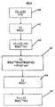
- the figure 8 shows a second alternative of the present invention.
- the first unit U1 calculates the coefficients H2 -1 that represent the second channel (STAGE 61 ) from a second sequence, typically a training sequence, s'(t) , sent from the second unit U2 (STAGE 60 ).
- the first unit U1 sends to the second unit U2 (STAGE 62 ) a first sequence H2 -1 *s(t) , which is the result of the convolution of a predetermined sequence s(t) and said coefficients H2 -1 that represent the second channel, said first sequence being forwarded as received by the second unit U2 to the first unit U1 in the form of a backward sequence.
- the first unit U1 receives the signal
- the first unit U1 calculates the coefficients H1 -1 that represent the first channel from the backward sequence, and predistorts the signal sent to the second unit U2 in terms of said coefficients that represent the first channel.
- the coefficients that represent the second channel are the inverse transfer function coefficients H2 -1 of the second channel and the coefficients H1 -1 that represent the first channel are the inverse coefficients of the convolution of said backward sequence received by the first unit U1 and of an inverted predetermined sequence s -1 (t) .
- the set of circuits 23 calculates the inverse transfer function coefficients H2 -1 of the second channel from the second sequence s (t) sent from the second unit U2 to the first unit U1 .
- this first unit U1 transmits to the second unit U2 a first sequence H2 -1 *s(t) , which is the result of the convolution of a predetermined sequence s(t) and the inverse transfer function coefficients H2 -1 of the second channel, said first convoluted sequence being forwarded exactly as received by the second unit U2 to the first unit U1 in the form of a backward sequence .
- the set of circuits 23 calculates the inverse transfer function coefficients of the first channel H1 -1 from this backward sequence.
- the predistortion coefficients are periodically updated with any of the algorithms of figures 7 and 8, which are applied repeatedly.
- predetermined sequence or “training sequence” are employed in the present description, these terms cover any signal that permits the inverse transfer function coefficients H1 -1 of the first channel to be determined, by using, for example, a blind equalization procedure to determine the coefficients that represent the channels H1 , H1*H2 , etc.
Abstract
Description
- calculating, in the first unit, coefficients that represent the second channel from a second predetermined sequence sent from the second unit to the first unit;
- sending by the first unit of a first predetermined sequence to the second unit, which forwards it in the form received to the first unit, in the form of a backward sequence;
- calculating, in said first unit, coefficients that represent the first and second channels together, from the received backward sequence; and
- predistorting the signal sent by the first unit by inverse transfer function coefficients of the first channel which are calculated in terms of said coefficients that represent the second channel and said coefficients that represent the first and second channels together.
- calculating, in the first unit, coefficients that represent the second channel from a second predetermined sequence sent from the second unit to the first unit;
- sending by the first unit to the second unit of a first sequence, which is the result of the convolution of a predetermined sequence and of said coefficients that represent the second channel, said first sequence being forwarded exactly as it is received by the second unit to the first unit in the form of a backward sequence;
- calculating, in said first unit, inverse transfer function coefficients of the first channel from said backward sequence; and
- predistorting the signal sent by the first unit in terms of said inverse transfer function coefficients of the first channel.
- means for calculating the coefficients that represent the second channel from a second predetermined sequence sent from the remote unit to the unit;
- means for sending a first predetermined sequence to the remote unit, which forwards it in the form received to said unit, in the form of a backward sequence;
- means for calculating the coefficients that represent the first and
second channels together, from the backward sequence received;
and is characterised in that: - said means for predistorting, predistort the transmitted signal by the inverse transfer function coefficients of the first channel, which are calculated in terms of said coefficients that represent the second channel and said coefficients that represent the first and second channels together.
- figure 1, already described, is a block diagram of a diversity receiver according to the state of the art;
- figure 2 shows a block diagram of two units according to the present invention;
- figure 3 shows a block diagram of a first unit of figure 2;
- figure 4 shows a block diagram of a second unit of figure 2;
- figure 5 is a block diagram of a predistorter circuit, included in the first unit of figure 2;
- figure 6 is a block diagram of a predistortion coefficient generator included in the first unit of figure 2;
- figure 7 shows a predistortion algorithm of a signal transmitted by the first unit according to a first implementation of the invention; and
- figure 8 shows a predistortion algorithm of a signal transmitted by the first unit according to a second implementation of the invention.
Claims (11)
- METHOD FOR DIVERSITY RECEPTION by a second unit (U2) of a CDMA signal sent by a first unit (U1) in a code division multiple access system, characterised by the predistortion (11) in said first unit (U1) of said signal prior to its transmission, said predistortion applying to the signal an effect appreciably opposite to the effect produced by a first channel (H1) over which said first unit (U1) sends data to said second unit (U2).
- METHOD according to claim 1, characterised in that said first unit (U1) sends data to said second unit (U2) over the first channel (H1) and said second unit (U2) sends data to said first unit (U1) over a second channel (H2), said method comprising the steps of:calculating, in the first unit, coefficients that represent the second channel (H2) from a second predetermined sequence (s(t)) sent from the second unit (U2) to the first unit (U1);
 sending by the first unit (U1) of a first predetermined sequence (s(t)) to the second unit (U2), which forwards it exactly as received to the first unit (U1), in the form of a backward sequence;calculating, in said first unit (U1), coefficients that represent the first and second channels together (H1*H2; (H1*H2) -1), from the received backward sequenceand
 predistorting the signal sent by the first unit by inverse transfer function coefficients (H1 -1) of the first channel, which are calculated in terms of said coefficients that represent the second channel (H2, H2 -1) and said coefficients that represent the first and second channels together (H1*H2, (H1*H2) -1).
 - METHOD according to claim 2, characterised in that said coefficients that represent the second channel are the inverse transfer function coefficients (H2 -1) of the second channel and said coefficients that represent the first and second channels together are the direct transfer function coefficients (H1*H2) of the first and second channels together, said predistortion being performed with the inverse coefficients (H1 -1) of the convolution of the inverse transfer function coefficients of the second channel (H2 -1) and of the direct transfer function coefficients of the first and second channels together (H1*H2).
- METHOD according to claim 2, characterised in that said coefficients that represent the second channel (H2) are the direct transfer function coefficients (H2) of the second channel and said coefficients that represent the first and second channels together are the inverse transfer function coefficients ((H1*H2)-1) of the first and second channels together, said predistortion being performed with the inverse coefficients (H1 -1) of the convolution of the direct transfer function coefficients of the second channel and of the inverse transfer function coefficients of the first and second channels together.
- METHOD according to claim 1, characterised in that said first unit (U1) sends data to said second unit (U2) over the first channel (H1) and said second unit (U2) sends data to said first unit (U1) over a second channel (H2), said method comprising the steps of:calculating, in the first unit, coefficients that represent the second channel (H2, H2 -1) from a second predetermined sequence (s
 calculating, in said first unit (U1), the inverse transfer function coefficients of the first channel (H1 -1) from said backward sequence; andpredistorting the signal sent by the first unit (U1) in terms of said inverse transfer function coefficients of the first channel.
 - METHOD according to claim 5, characterised in that said coefficients that represent the second channel are the inverse transfer function coefficients (H2 -1) of the second channel (U2) and said coefficients (H1 -1) that represent the first channel (U1) are the inverse coefficients of the convolution of said backward sequencereceived by the first unit (U1) and of a predetermined inverse sequence (s -1 (t)).

- UNIT (U1) of a telecommunications system for sending a signal to a remote unit (U2) over a first channel (H1), comprising means (10) for multiplying the signal to be sent by a CDMA code that is in the form of a CDMA code sequence, characterised in that it comprises a predistorter circuit (11) for predistorting said signal to be sent by applying to said signal an effect appreciably opposite to the effect produced by the transmission channel.
- UNIT according to claim 7, characterised in that it comprises:means (53) for calculating the coefficients that represent the second channel (H2) from a second predetermined sequence (s
and in that said means for predistorting (11), predistort the signal sent (S(t)) by the inverse transfer function coefficients of the first channel, which are calculated in terms of said coefficients that represent the second channel (H2, H2 -1) and said coefficients that represent the first and second channels together ({H1*H2} -1, {H1*H2}). - REMOTE UNIT for forwarding to unit (U1) according to claim 8, exactly as received, said first predetermined sequence (s(t)), in the form of a backward sequence, characterised in that it comprises:means for connecting, in a manner synchronised with an incoming predetermined sequence (s(t)), an output of a downlink converter with an input of an uplink converter.
- UNIT according to claim 8, characterised in that the means (53) for calculating the coefficients that represent the second channel (H2) calculate the inverse transfer function coefficients (H2 -1) of the second channel; the means (51) for calculating the coefficients that represent the first and second channels together (H1*H2) calculate the direct transfer function coefficients (H1*H2) of the first and second channels together; and the means for predistorting (11), predistort the signal to be sent with the inverse coefficients (H1 -1) of the convolution of the inverse transfer function coefficients of the second channel (H2 -1) and of the direct transfer function coefficients of the first and second channels together (H1*H2).
- UNIT according to claim 8, characterised in that the means (53) for calculating the coefficients that represent the second channel (H2) calculate the direct transfer function coefficients (H2) of the second channel; the means (51) for calculating the coefficients that represent the first and second channels together (H1*H2) calculate the inverse transfer function coefficients ((H1*H2) -1) of the first and second channels together; and the means for predistorting (11), predistorts the signal to be sent with the inverse coefficients (H1 -1) of the convolution of the direct transfer function coefficients of the second channel and of the inverse transfer function coefficients of the first and second channels together.
Applications Claiming Priority (2)
| Application Number | Priority Date | Filing Date | Title |
|---|---|---|---|
| ES9900152 | 1999-01-26 | ||
| ES9900152 | 1999-01-26 |
Publications (2)
| Publication Number | Publication Date |
|---|---|
| EP1024608A2 true EP1024608A2 (en) | 2000-08-02 |
| EP1024608A3 EP1024608A3 (en) | 2003-11-05 |
Family
ID=8307068
Family Applications (1)
| Application Number | Title | Priority Date | Filing Date |
|---|---|---|---|
| EP00400058A Withdrawn EP1024608A3 (en) | 1999-01-26 | 2000-01-12 | Method for diversity reception of a cdma signal and corresponding transmitter |
Country Status (1)
| Country | Link |
|---|---|
| EP (1) | EP1024608A3 (en) |
Cited By (1)
| Publication number | Priority date | Publication date | Assignee | Title |
|---|---|---|---|---|
| WO2005083961A1 (en) * | 2004-02-27 | 2005-09-09 | Vixs Systems Inc. | Method and apparatus for non-intrusive transceiver property adjustment |
Citations (5)
| Publication number | Priority date | Publication date | Assignee | Title |
|---|---|---|---|---|
| US5282222A (en) * | 1992-03-31 | 1994-01-25 | Michel Fattouche | Method and apparatus for multiple access between transceivers in wireless communications using OFDM spread spectrum |
| WO1997008861A1 (en) * | 1995-08-25 | 1997-03-06 | Terayon Corporation | Apparatus and method for digital data transmission |
| US5636244A (en) * | 1995-07-26 | 1997-06-03 | Motorola, Inc. | Method and apparatus for initializing equalizer coefficents using peridioc training sequences |
| EP0866567A2 (en) * | 1997-03-11 | 1998-09-23 | Alcatel | Transmission/reception unit with bidirectional equalization |
| EP0936781A1 (en) * | 1998-02-16 | 1999-08-18 | Alcatel | Method for pre-distorting signals transmitted over non-reciprocal channels |
-
2000
- 2000-01-12 EP EP00400058A patent/EP1024608A3/en not_active Withdrawn
Patent Citations (5)
| Publication number | Priority date | Publication date | Assignee | Title |
|---|---|---|---|---|
| US5282222A (en) * | 1992-03-31 | 1994-01-25 | Michel Fattouche | Method and apparatus for multiple access between transceivers in wireless communications using OFDM spread spectrum |
| US5636244A (en) * | 1995-07-26 | 1997-06-03 | Motorola, Inc. | Method and apparatus for initializing equalizer coefficents using peridioc training sequences |
| WO1997008861A1 (en) * | 1995-08-25 | 1997-03-06 | Terayon Corporation | Apparatus and method for digital data transmission |
| EP0866567A2 (en) * | 1997-03-11 | 1998-09-23 | Alcatel | Transmission/reception unit with bidirectional equalization |
| EP0936781A1 (en) * | 1998-02-16 | 1999-08-18 | Alcatel | Method for pre-distorting signals transmitted over non-reciprocal channels |
Cited By (1)
| Publication number | Priority date | Publication date | Assignee | Title |
|---|---|---|---|---|
| WO2005083961A1 (en) * | 2004-02-27 | 2005-09-09 | Vixs Systems Inc. | Method and apparatus for non-intrusive transceiver property adjustment |
Also Published As
| Publication number | Publication date |
|---|---|
| EP1024608A3 (en) | 2003-11-05 |
Similar Documents
| Publication | Publication Date | Title |
|---|---|---|
| US6285859B1 (en) | Method for predistortion of a signal transmitted between two units of a telecommunications network and a unit for carrying out the method | |
| US9178727B2 (en) | FBMC receiver with carrier frequency offset compensation | |
| US5872814A (en) | Method for linearization of RF transmission electronics using baseband pre-distortion in T/R compensation pilot signals | |
| KR100312836B1 (en) | Adaptive array transceiver | |
| KR101061743B1 (en) | Communication Receiver with Adaptive Equalizer Using Channel Estimation | |
| KR100827099B1 (en) | Apparatus and method for estimating carrier to interference noise ratio in an orthogonal frequency division multiple system | |
| US8644265B2 (en) | Wideband analog channel information feedback | |
| US6301316B1 (en) | Frequency sharing mobile communication system equipped with diversity receiver incorporated with shared wave canceller | |
| JP2005323384A (en) | Linear filter equalizer | |
| KR20020075569A (en) | Data communication apparatus and method based on the Orthogonal Frequency Division Multiple Access | |
| JP4847313B2 (en) | Equalization of received multiple signals for soft handoff in wireless communication systems | |
| KR19980080067A (en) | Transceiver unit with bidirectional equalization | |
| US11374613B2 (en) | Active interference cancellation apparatus, signal isolation control apparatus and method of actively cancelling interference | |
| US20010026578A1 (en) | Code division multiple access transmitter and receiver | |
| EP1942581A1 (en) | Signal receiving apparatus including equalizer, terminal apparatus, signal receiving method, and signal receiving program | |
| JPH0795655A (en) | Mobile communication system | |
| EP1024608A2 (en) | Method for diversity reception of a cdma signal and corresponding transmitter | |
| JP3146196B2 (en) | OFDM demodulator | |
| KR100937467B1 (en) | Reduced complexity sliding window based equalizer | |
| KR20060066255A (en) | Apparatus and method for correlation using symmetry of multiplying coefficients | |
| JP2003069530A (en) | Multicarrier cdma receiver | |
| JP2655116B2 (en) | CDMA transceiver | |
| KR100976726B1 (en) | On-channel repeater and its method | |
| KR101058734B1 (en) | Apparatus and method for canceling echo signal in signal transmission / reception device of communication system | |
| JP4195346B2 (en) | Interference wave canceling device |
Legal Events
| Date | Code | Title | Description |
|---|---|---|---|
| PUAI | Public reference made under article 153(3) epc to a published international application that has entered the european phase |
Free format text: ORIGINAL CODE: 0009012 |
|
| AK | Designated contracting states |
Kind code of ref document: A2 Designated state(s): AT BE CH CY DE DK ES FI FR GB GR IE IT LI LU MC NL PT SE |
|
| AX | Request for extension of the european patent |
Free format text: AL;LT;LV;MK;RO;SI |
|
| PUAL | Search report despatched |
Free format text: ORIGINAL CODE: 0009013 |
|
| AK | Designated contracting states |
Kind code of ref document: A3 Designated state(s): AT BE CH CY DE DK ES FI FR GB GR IE IT LI LU MC NL PT SE |
|
| AX | Request for extension of the european patent |
Extension state: AL LT LV MK RO SI |
|
| RIC1 | Information provided on ipc code assigned before grant |
Ipc: 7H 04L 5/14 B Ipc: 7H 04L 25/02 B Ipc: 7H 04L 25/03 A |
|
| STAA | Information on the status of an ep patent application or granted ep patent |
Free format text: STATUS: THE APPLICATION IS DEEMED TO BE WITHDRAWN |
|
| 18D | Application deemed to be withdrawn |
Effective date: 20030801 |