-
The present invention relates to an optical switch
and an optical switch system which are used in optical
communication and photonic switching, particularly to an
optical switch and an optical switch system in which the
necessary amount of hardware can be reduced.
-
In photonic switching such as an optical cross-connecting
system in which a light signal is used as light
without being converted to an electric signal in a node to
edit a light propagation path, a node scale can be reduced,
which contributes to communication cost reduction. An
optical switch technique is important for constituting such
node. As a conventional optical switch, there have been
proposed a switch prepared using lithium niobate, an
optical crossbar switch using a semiconductor optical
amplifier as a gate switch, and the like. Various
proposals have also been submitted for optical switch
systems such as an optical switch network using these
optical switches.
-
For example, a conventional optical switch system
aiming at application to an interconnected network of
parallel computers is proposed in the Proceedings for 1996
General Convention of the Institute of Electronics,
Information and Communication Engineers of Japan (IEICE),
No. SB-9-5. In this optical switch system, an optical
crossbar switch employing a semiconductor optical amplifier
as a gate switch is used. Moreover, an optical switch
network in which a transmission capacity per port is
increased by using a wavelength-division multiplexing
technology is also proposed in the Proceedings of 1996
Communication Society meeting of IEICE, No.B-1072.
-
However, the optical crossbar switch used in the
above-described conventional optical switch system requires
semiconductor optical amplifiers by the square of the
number of input/output ports. Therefore, when switch scale
increases, cost rapidly increases. There is further
problem that it becomes very difficult to mount the switch.
For example, a 4 × 4 optical crossbar switch with four
input ports and four output ports requires 16 semiconductor
optical amplifiers, but a 16 × 16 optical crossbar switch
requires 256 amplifiers, and a 64 × 64 optical crossbar
switch requires 4096 semiconductor optical amplifiers.
-
Moreover, in the optical switch system using the
wavelength-division multiplexing technology, in order to
reduce the number of gates, a wavelength-division
multiplexing light source is necessary. This raises a
problem that it becomes difficult to inexpensively
constitute the optical switch system.
-
An object of the present invention is to provide
an optical switch system which can reduce the number of
necessary optical switches and which is small in size and
low in cost.
-
According to the present invention, there is
provided an optical switch comprising: at least one optical
fiber pair arranged so that light emitted from a first
optical fiber is coupled to a second optical fiber via a
void; and an optical breaker for interrupting the optical
coupling between the first and second optical fibers.
-
According to the present invention, there is
provided an optical switch system comprising: at least one
optical branching unit for branching at least one input
light signal to a predetermined number of branched output
lights; at least one optical combining unit for combining
one of the branched output lights of at least one optical
branching unit; and at least one optical switch inserted
between the optical branching unit and at least one optical
combining unit to which each of the branched output lights
of the optical branching unit is supplied.
-
The above and other objects, features and
advantages of the present invention will become more
apparent from the following detailed description when taken
in conjunction with the accompanying drawings wherein:
- Fig. 1 is a perspective view of an array type
space optical switch according to a first embodiment of the
present invention;
- Fig. 2 is a sectional view showing that an
interrupting plate is not inserted in a space propagation
part in the array type space optical switch of Fig. 1;
- Fig. 3 is a sectional view showing that the
interrupting plate is inserted in the space propagation
part in the array type space optical switch shown in Fig.
1;
- Fig. 4 is a sectional view of the array type space
optical switch according to a second embodiment of the
present invention;
- Fig. 5 is a plan view of the interrupting plate
included in the constitution of Fig. 4;
- Fig. 6 is a diagram showing the constitution of
the array type space optical switch according to a third
embodiment of the present invention;
- Fig. 7 is a diagram showing the constitution of
the array type space optical switch according to a fourth
embodiment of the present invention;
- Fig. 8 is a diagram showing the constitution of
the array type space optical switch according to a fifth
embodiment of the present invention;
- Fig. 9 is a diagram showing the constitution of a
movable part 41;
- Fig. 10 is a diagram showing the constitution of
the array type space optical switch according to a sixth
embodiment of the present invention;
- Fig. 11 is a diagram showing the constitution of a
matrix type optical circuit to which an optical switch
system is applied according to a seventh embodiment of the
present invention;
- Fig. 12 is a diagram showing the constitution of
an optical cross-connecting system according to the seventh
embodiment of the present invention;
- Fig. 13 is a diagram showing the constitution of
the optical cross-connecting system according to an eighth
embodiment of the present invention;
- Fig. 14 is a diagram showing the constitution of
the optical cross-connecting system according to a ninth
embodiment of the present invention;
- Fig. 15 is a diagram showing the constitution of
the optical cross-connecting system according to a tenth
embodiment of the present invention; and
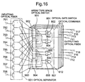
- Fig. 16 is a diagram showing the constitution of
the optical cross-connecting system according to an
eleventh embodiment of the present invention.
-
-
Embodiments of the present invention will next be
described with reference to the drawings.
(First Embodiment)
-
Fig. 1 is a perspective view schematically showing
an array type space optical switch as an optical switch
according to a first embodiment of the present invention.
As shown in Fig. 1, in an array type space optical switch
10 of the present embodiment, one end of each of optical
fibers 101a to 104a, 101b to 104b is fixed to support
members 105a, 105b. The optical fibers 101a and 101b form
one pair, and have end surfaces opposite to each other, and
the optical fibers 102a and 102b form one pair, and have
end surfaces opposite to each other. Moreover, the optical
fibers 103a and 103b form one pair, and have end surfaces
opposite to each other, and the optical fibers 104a and
104b form one pair, and have end surfaces opposite to each
other. A space propagation part 200 is formed between the
end surfaces of the optical fibers 101a to 104a and 101b to
104b.
-
The array type space optical switch 10 of the
present embodiment is provided with an interrupting plate
300 to be inserted to or extracted from the space
propagation part 200. Here, an optical element for
collimating the light passing through the space propagation
part 200 may be disposed in the space propagation part 200.
Thereby, the lights emitted from the end surfaces of the
optical fibers 101a to 104a on the side of the support
member 105a are collimated in the space propagation part
200, and coupled to the optical fibers corresponding to the
optical fibers 101a to 104a.
-
A method of manufacturing the array type space
optical switch 10 of the present embodiment is as follows.
First, a part of each of four optical fibers is removed to
form the optical fibers 101a to 104a, 101b to 104b, and the
space propagation part 200. Subsequently, the array type
space optical switch 10 is provided with the interrupting
plate 300 which can move in a direction perpendicular to a
propagation direction of the lights emitted from the end
surfaces of the optical fibers 101a to 104a on the side of
the support member 105a.
-
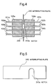
Fig.2 is a sectional view showing that the
interrupting plate 300 is not inserted in the space
propagation part 200 in the array type space optical switch
10 shown in Fig. 1. In the state shown in Fig. 2, a signal
light inputted to the array type space optical switch 10 is
propagated in the space propagation part 200, and outputted
from the array type space optical switch 10. By disposing
collimators such as collimating lenses on the output ends
of the optical fibers 101a to 104a, lights can be
propagated keeping collimated in the space propagation part
200. Moreover, when multi-mode fibers are used as the
optical fibers 101b to 104b, the output lights of the
optical fibers 101a to 104a can be coupled to the optical
fibers 101b to 104b with a low loss without using any
collimator.
-
In the state shown in Fig. 2, a signal light of
1550 nm band is inputted to the array type space optical
switch 10 from the end surface of each of the optical
fibers 101a to 104a on the opposite side of the support
member 105a. In this case, the signal light emitted from
the end surface of the optical fiber 101a on the side of
the support member 105a is propagated toward the optical
fiber 101b. The signal light emitted from the end surface
of the optical fiber 102a on the side of the support member
105a is propagated toward the optical fiber 102b. The
signal light emitted from the end surface of the optical
fiber 103a on the side of the support member 105a is
propagated toward the optical fiber 103b. The signal light
emitted from the end surface of the optical fiber 104a on
the side of the support member 105a is propagated toward
the optical fiber 104b. Therefore, while the interrupting
plate 300 is not interrupted in the space propagation part
200, optical transmission paths in the array type space
optical switch 10 are all turned on.
-
Fig. 3 is a sectional view showing that the
interrupting plate 300 is inserted in the space propagation
part 200 in the array type space optical switch 10 shown
in Fig. 1. As shown in Fig. 3, when the interrupting plate
300 is inserted in the space propagation part 200, the
signal lights inputted to the array type space optical
switch 10 from the end surfaces of the optical fibers 101a
to 104a on the opposite side of the support member 105a are
interrupted by the interrupting plate 300, and are not
outputted from the array type space optical switch 10. In
this case, the state in which all the optical transmission
paths are turned on is switched to a state in which all the
optical transmission paths in the array type space optical
switch 10 are turned off.
-
As described above, by inserting the interrupting
plate 300 to the space propagation part 200, or extracting
the interrupting plate 300 from the space propagation part
200, the switching on or off of a plurality of pairs of
optical fibers can be performed altogether, in which each
pair is formed by two optical fibers having their end
surfaces opposite to each other.
(Second Embodiment)
-
Fig. 4 is a sectional view showing the array type
space optical switch as the optical switch according to a
second embodiment of the present invention. Moreover, Fig.
5 is a plan view of an interrupting plate 310 in Fig. 4.
The array type space optical switch of the second
embodiment is different from that of the first embodiment
in the shape of the interrupting plate 310 inserted in the
space propagation part 200. In Fig. 4, the same
constituting components as those of the first embodiment
are denoted by the same reference numerals, and respects
different from those of the first embodiment will mainly be
described hereinafter.
-
As shown in Fig. 4, the array type space optical
switch of the second embodiment is provided with the
interrupting plate 310 to be inserted to the space
propagation part 200 or extracted from the space
propagation part 200, instead of the interrupting plate 300
used in the first embodiment. In this interrupting plate
310, a notch part 310a is formed as shown in Figs. 4 and 5.
The notch part 310a is disposed in positions corresponding
to the optical fibers 102a, 102b when the interrupting
plate 310 is inserted to the space propagation part 200.
When the interrupting plate 310 is inserted to the space
propagation part 200, the signal light is propagated
between the optical fibers 102a and 102b via the space
propagation part 200.
-
In the second embodiment, a signal light of 1300
nm band is inputted to the array type space optical switch
from each end surface of the optical fibers 101a to 104a on
the opposite side of the support member 105a. In an on
state in which the interrupting plate 310 is not inserted
to the space propagation part 200, and the interrupting
plate 310 is disposed outside the space propagation part
200, in the same manner as in the first embodiment, the
signal light inputted to the array type space optical
switch from each end surface of the optical fibers 101a to
104a is passed through the space propagation part 200 and
outputted from the array type space optical switch.
-
From the above-described on state of the array
type space optical switch, when only the signal light
inputted to the optical fiber 102a among the signal lights
inputted to the optical fibers 101a to 104a is outputted
from the array type space optical switch, the interrupting
plate 310 is inserted to the space propagation part 200 and
the interrupting plate 310 is disposed in the space
propagation part 200. Thereby, the signal lights inputted
to the optical fibers 101a, 103a, 104a are interrupted by
the interrupting plate 310, and only the signal light
inputted to the optical fiber 102a is outputted through the
space propagation part 200 and the optical fiber 102b.
-
As described above, in the array type space
optical switch of the second embodiment, the interrupting
plate 310 is configured so that photonic switching is
performed once in all the pairs of optical fibers excluding
the pair of the optical fibers 102a, 102b in a plurality of
optical fibers.
(Third Embodiment)
-
Fig. 6 is a diagram schematically showing the
constitution of the array type space optical switch as the
optical switch according to a third embodiment of the
present invention. As shown in Fig. 6, the array type
space optical switch of the third embodiment is provided
with interrupting plates 301 to 304 to be inserted to the
space propagation part or extracted from the space
propagation part. By inserting the interrupting plate 301
to the space propagation part 200, the signal light is
interrupted between optical fibers 12a and 12e, between
optical fibers 13a and 13e, and between optical fibers 14a
and 14e. On the other hand, the signal light is propagated
between the optical fibers 11a and 11e via the space
propagation part 200.
-
A notch part 302a is formed in the interrupting
plate 302. When the interrupting plate 302 is inserted to
the space propagation part 200, the notch part 302a is
disposed in a position corresponding to a light propagation
path between the optical fibers 12a and 12e. By inserting
the interrupting plate 302 to the space propagation part
200, the signal light is interrupted between the optical
fibers 11a and 11e, between the optical fibers 13a and 13e,
and between the optical fibers 14a and 14e. On the other
hand, the signal light is propagated between the optical
fibers 12a and 12e via the space propagation part 200.
-
The interrupting plate 303 is inserted to the
space propagation part 200. A notch part 303a is formed in
the interrupting plate 303. When the interrupting plate
303 is inserted to the space propagation part 200, the
notch part 303a is disposed in a position corresponding to
a light propagation path between the optical fibers 13a and
13e. By inserting the interrupting plate 303 to the space
propagation part 200, the signal light is interrupted
between the optical fibers 11a and 11e, between the optical
fibers 12a and 12e, and between the optical fibers 14a and
14e, and the signal light is propagated between the optical
fibers 13b and 13c via a space propagation part 200c.
-
The interrupting plate 304 is inserted to the
space propagation part 200. By inserting the interrupting
plate 304 to the space propagation part 200, the signal
light is interrupted between the optical fibers 11a and 11e,
between the optical fibers 12a and 12e, and between the
optical fibers 13a and 13e, and the signal light is
propagated between the optical fibers 14a and 14e via the
space propagation part 200.
-
A method of manufacturing the array type space
optical switch 10 of the third embodiment is as follows.
First, four optical fibers are prepared, and parts of the
four optical fibers corresponding to the space propagation
part 200 are removed to form the space propagation part 200.
Subsequently, the array type space optical switch is
provided with the interrupting plates 301 to 304 which can
move in the direction perpendicular to the optical fibers.
-
In the third embodiment, the signal light of 1550
nm band is inputted to the array type space optical switch
from each end surface of the optical fibers 11a to 14a on
the opposite side of the optical fibers 11e to 14e. Here,
when only the light inputted to the optical fiber 13a is
outputted from the optical switch among the lights inputted
to the optical fibers 11a to 14a, from the state in which
the interrupting plate is not inserted to the space
propagation part 200, the interrupting plate 303 is
inserted. Thereby, the on state of the array type space
optical switch to all the sets of the optical fibers is
switched to the state in which only the signal light from
the optical fiber 13a is outputted from the optical switch,
because the outputs of the signal lights from the optical
fibers 11a, 12a, 14a are interrupted by the interrupting
plate 303. Similarly, by inserting either one of the
interrupting plates 301, 302, 304 to the space propagation
part 200, the light can be taken out of an arbitrary light
output port in the optical switch.
-
As described above, in the array type space
optical switch of the third embodiment, with respect to a
plurality of sets of optical fibers, each set being
constituted of a plurality of optical fibers for
constituting one light transmission path, the photonic
switching of all the sets of optical fibers excluding a
specific set of optical fibers in a plurality of sets of
optical fibers is performed. The array type space optical
switch is provided with the interrupting plates 301 to 304
each of which corresponds to each set of the plurality of
sets of optical fibers. Each of the interrupting plates
301 to 304 performs the photonic switching in all the sets
of optical fibers excluding the set of optical fibers
corresponding to each of the interrupting plates 301 to 304
among the plurality of sets of optical fibers.
(Fourth Embodiment)
-
Fig. 7 is a schematic view showing the
constitution of the array type space optical switch as the
optical switch according to a fourth embodiment of the
present invention. The array type space optical switch of
the fourth embodiment is different from that of the first
embodiment in the shape of the interrupting plate inserted
in the space propagation part. In Fig. 7, the same
constituting components as those of the first embodiment
are denoted by the same reference numerals, and respects
different from those of the first embodiment will mainly be
described hereinafter.
-
As shown in Fig. 7, the array type space optical
switch of the fourth embodiment is provided with an
interrupting plate 305 for interrupting the light between
the optical fibers 101a and 101b, an interrupting plate 306
for interrupting the light between the optical fibers 102a
and 102b, and interrupting plate 307 for interrupting the
light between the optical fibers 103a and 103b, and an
interrupting plate 308 for interrupting the light between
the optical fibers 104a and 104b, instead of the
interrupting plate 300 used in the first embodiment.
-
When the light is interrupted between the optical
fibers 101a and 101b, the interrupting plate 305 is
inserted in a part between the optical fibers 101a and 101b
in the space propagation part 200. When the light is
interrupted between the optical fibers 102a and 102b, the
interrupting plate 306 is inserted in a part between the
optical fibers 102a and 102b in the space propagation part
200. When the light is interrupted between the optical
fibers 103a and 103b, the interrupting plate 307 is
inserted in a part between the optical fibers 103a and 103b
in the space propagation part 200. When the light is
interrupted between the optical fibers 104a and 104b, the
interrupting plate 308 is inserted in a part between the
optical fibers 104a and 104b in the space propagation part
200.
-
In the fourth embodiment, the signal light of 1550
nm band is inputted to the array type space optical switch
from each end surface of the optical fibers 101a to 104a on
the opposite side of the optical fibers 101e to 104e. Here,
when the lights inputted to the optical fibers 102a, 103a
are outputted from the optical switch among the lights
inputted to the optical fibers 101a to 104a, the
interrupting plates 305, 308 are inserted in the space
propagation part 200. Thereby, the output light from the
optical fiber 101a is interrupted by the interrupting plate
305, and the output light from the optical fiber 104a is
interrupted by the interrupting plate 308. Thereby, the
state is switched to the state in which only the signal
lights from the optical fibers 102a, 103a are outputted
from the optical switch. Similarly, by inserting either
one of the interrupting plates to the space propagation
part, the light can be taken out of an arbitrary light
output port in the optical switch. In this case, the
interrupting plates 305, 308 are inserted to the space
propagation part 200, but by using appropriate driving
force transmitting means for moving the interrupting plates
305, 308, a plurality of interrupting plates can
simultaneously be moved by one switching driving.
Therefore, by controlling each operation of the
interrupting plates 305 to 308, the light can be taken out
of the arbitrary light output port in the array type space
optical switch of the fourth embodiment.
(Fifth Embodiment)
-
Fig. 8 is a schematic view showing the
constitution of the array type space optical switch as the
optical switch according to a fifth embodiment of the
present invention. The array type space optical switch of
the fifth embodiment is different from that of the first
embodiment in that the photonic switching is performed in
the space propagation part 200 by moving the end of the
optical fiber without using the interrupting plate. In Fig.
8, the same constituting components as those of the first
embodiment are denoted by the same reference numerals, and
respects different from those of the first embodiment will
mainly be described hereinafter.
-
As shown in Fig. 8, in the array type space
optical switch of the fifth embodiment, the end of the
optical fiber 101a on the side of the optical fiber 101b
forms a movable part 41, and the end of the optical fiber
102a on the side of the optical fiber 102b forms a movable
part 42. Moreover, the end of the optical fiber 103a on
the side of the optical fiber 103b forms a movable part 43,
and the end of the optical fiber 103a on the side of the
optical fiber 103b forms a movable part 43, and the end of
the optical fiber 104a on the side of the optical fiber
104b forms a movable part 44. The movable parts 41 to 44
are moved by moving means disposed on the array type space
optical switch of the fifth embodiment.
-
Various constitutions can be applied to the moving
means. Here, the utilization of a magnetic field will be
described as one example. The constitution is shown in Fig.
9. In the constitution, a magnetic material 110 is applied
to each end of the optical fibers 101a to 104a on the side
of the space propagation part 200. An electromagnet is
disposed so that the magnetic field acts on the magnetic
member. When the electromagnet is not energized, that is,
when there is no magnetic field, the lights outputted from
the optical fibers 101a to 104a are coupled to the optical
fibers 101b to 104b. On the other hand, when the
electromagnet is energized, each end of the optical fibers
101a to 104a is deflected, and accordingly the output
lights are not coupled to the optical fibers 101b to 104b.
Specifically, by turning on/off the power to the
electromagnet, the photonic switching can be performed.
-
In the fifth embodiment, the signal light of 1550
nm band is inputted to the array type space optical switch
from each end surface of the optical fibers 101a to 104a on
the opposite side of the optical fibers 101b to 104b. When
the light inputted to the optical fiber 101a is transmitted
to the optical fiber 101b through the space propagation
part 200, the end surface of the movable part 41 is moved
to be opposite to the end surface of the optical fiber 101b
on the side of the optical fiber 101a by the moving means.
Additionally, the optical axis of the movable part 41 is
allowed to coincide with the optical axis of the end of the
optical fiber 101b on the side of the optical fiber 101a.
When the optical coupling is released between the optical
fibers 101a and 101b to obtain the off state, the movable
part 41 is moved by the moving means so that the optical
axis of the movable part 41 deviates from the optical axis
of the end of the optical fiber 101b, and the signal light
emitted from the end surface of the movable part 41 is
emitted in a direction different from the direction toward
the optical fiber 101b. The photonic switching can be
performed between the optical fibers 101a and 101b by
moving the movable part 41 in this manner.
-
Similarly, the photonic switching can be performed
by moving the movable parts 42 to 44 by the moving means to
control the optical space coupling also between the optical
fibers 102a and 102b, between the optical fibers 103a and
103b, and between the optical fibers 104a and 104b.
-
Here, when the lights inputted to the optical
fibers 102a, 103a among the lights inputted to the optical
fibers 101a to 104a are outputted, the movable parts 41, 44
are moved by the moving means to release the optical
coupling of the optical fibers 101a and 101b, and the
optical coupling of the optical fibers 104a and 104b.
Thereby, the state in which the array type space optical
switch is on to all the pairs of the optical fibers is
switched to the state in which the signal light outputs
from the optical fibers 101a, 104a are interrupted and the
signal lights from the optical fibers 102a, 103a are
outputted.
-
In this case, the operation of the movable parts
41, 44 is controlled, but by using appropriate moving means
to move the movable parts 41 to 44, a plurality of movable
parts can simultaneously be controlled by one switch
driving by the moving means. Therefore, by controlling the
movable parts 41 to 44 by the moving means, the light can
be taken out of the arbitrary light output port in the
array type space optical switch of the fifth embodiment.
-
Moreover, the array type space optical switch may
comprise a plurality of power transmitting means of the
sets of the optical fibers for moving one end of the
optical fiber in each set of optical fibers with respect to
a plurality of sets of optical fibers. Thereby, the degree
of freedom in selecting the optical fiber to be switched
from the plurality of sets of optical fibers.
(Sixth Embodiment)
-
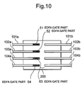
Fig. 10 is a schematic view showing the
constitution of the array type space optical switch as the
optical switch according to a sixth embodiment of the
present invention. In Fig. 10, the same constituting
components as those of the first embodiment are denoted by
the same reference numerals. The array type space optical
switch of the sixth embodiment is different from that of
the first embodiment in that optical amplifiers formed on
the ends of the optical fibers are used in performing the
photonic switching in the space propagation part 200
without using any interrupting plate. The respects
different from the first embodiment will mainly be
described hereinafter.
-
As shown in Fig. 10, in the array type space
optical switch of the sixth embodiment, erbium-doped fiber
amplifier (EDFA) gate parts 51 to 54 are formed on the
parts of the optical fibers 101a to 104a adjacent to the
space propagation part 200. The EDFA gate parts 51 to 54
comprise erbium-doped fibers formed by doping erbium (Er)
to the ends of the optical fibers. In each of these EDFA
gate parts 51 to 54, by controlling the intensity of a
pumping light injected to the EDFA gate part, the switching
of the array type space optical switch in each set of
optical fibers is performed.
-
In the sixth embodiment, the signal light of 1550
nm band is inputted to the array type space optical switch
from each end surface of the optical fibers 101a to 104a on
the opposite side of the optical fibers 101b to 104b. When
the lights inputted to the optical fibers 102a, 103a among
the lights inputted to the optical fibers 101a to 104a are
outputted, the pumping lights inputted to the EDFA gate
parts 51, 54 are interrupted. Thereby, the on state of the
array type space optical switch to all the sets of optical
fibers is switched to the state in which the outputs of the
signal lights from the optical fibers 101a, 104a are
interrupted by the EDFA gate parts 51, 54 and the signal
lights from the optical fibers 102a, 103a are outputted.
-
In this case, the EDFA gate parts 51, 54 are
controlled, but by using control means provided with
appropriate pumping light transmitting means, a plurality
of EDFA gate parts can simultaneously be controlled with
one control to output the pumping lights. Therefore, the
light can be taken out of the arbitrary light output port
in the array type space optical switch of the sixth
embodiment by using the control means to control the EDFA
gate parts 51 to 54.
-
Since the light power loss in the optical switch
can be compensated by using the erbium-doped optical fiber
amplifier to perform the photonic switching in the array
type space optical switch in this manner, there is an
advantage that the margin of an input light power increases
in a light receiver using the array type space optical
switch.
-
The array type space optical switch of the sixth
embodiment may be provided with control means for
controlling all the EDFA gate parts 51 to 54 to perform one
photonic switching in a plurality of sets of optical fibers,
or control means for controlling the EDFA gate parts 51 to
54 to perform one photonic switching in all the sets of
optical fibers excluding a specific set of optical fibers
among the plurality of sets of optical fibers. Furthermore,
there may be provided a plurality of driving means for the
plurality of sets of optical fibers, so that each of the
plurality of driving means controls the operation of the
EDFA gate part in one set of optical fibers corresponding
to the driving means to perform the photonic switching. In
this case, the degree of freedom is widened in selecting
the set of optical fibers in which the photonic switching
is to be performed from the plurality of sets of optical
fibers.
-
Moreover, instead of forming the EDFA gate parts
51 to 54 on the optical fibers 101a to 104a in the array
type space optical switch of the sixth embodiment, a
plurality of optical attenuators corresponding to the
optical fibers 101a to 104a, or one optical attenuator may
be used to perform the switching of the lights inputted to
the optical fibers 101a to 104a.
(Seventh Embodiment)
-
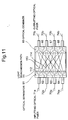
Fig. 11 is a schematic view showing the
constitution of a matrix type optical circuit to which the
optical switch system of a seventh embodiment of the
present invention is applied. The optical circuit shown in
Fig. 11 is a 4 × 4 matrix type optical circuit which
comprises four light input ports and four light output
ports. As shown in Fig. 11, inputting optical fibers 71a
to 74a are attached to the light input ports, and
outputting optical fibers 71b to 74b are attached to the
light output ports. One end of the inputting optical fiber
71a on the side of the outputting optical fiber 71b is
connected to an optical separator 61 which branches the
input light to the inputting optical fiber 71a into light
transmission paths 111 to 114. The light transmission
paths 111 to 114 are constituted of a plurality of optical
fibers and array type space optical switches as described
later based on Fig. 12. Each end of the inputting optical
fibers 72a to 74a on the side of the outputting optical
fibers is also connected to optical separators 62 to 64
which branch the input lights to the inputting optical
fibers into four light transmission paths.
-
On the other hand, one end of the outputting
optical fiber 71b on the side of the inputting optical
fiber 71a is connected to an optical combiner 65 which
combines the lights from the four light transmission paths.
The optical combiner 65 is connected to the light
transmission path 111 out of the four light transmission
paths branched by the optical separator 61, one of the four
light transmission paths branched by the optical separator
62, one of the four light transmission paths branched by
the optical separator 63, and one of the four light
transmission paths branched by the optical separator 64.
Therefore, each one of the four light transmission paths
divided by the optical separators 61 to 64 is coupled by
the optical combiner 65, and the light inputted to the four
light transmission paths coupled by the optical combiner 65
is outputted to the outputting optical fiber 71b through
the optical combiner 65.
-
Each one end of the outputting optical fibers 72b
to 74b on the side of the inputting optical fibers is also
connected to optical combiners 66 to 68 each of which
couples each one of four light transmission paths branched
by the optical separators 61 to 64. Thereby, the light
inputted to the four light transmission paths combined by
the optical combiner 66 is outputted to the outputting
optical fiber 72b through the optical combiner 66.
Moreover, the light inputted to the four light transmission
paths combined by the optical combiner 67 is outputted to
the outputting optical fiber 73b through the optical
combiner 67, and the light inputted to the four light
transmission paths combined by the optical combiner 68 is
outputted to the outputting optical fiber 74b through the
optical combiner 68.
-
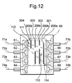
Fig. 12 is a schematic view showing the
constitution of an optical cross-connecting system as the
optical switch system of the seventh embodiment. As shown
in Fig. 12, in the optical cross-connecting system of the
seventh embodiment, used is the constitution similar to the
constitution of the array type space optical switch of the
third embodiment which has the movable interrupting plates
301 to 304. This optical cross-connecting system is
provided with four switches with the constitution similar
to that of the array type space optical switch of the third
embodiment, and the array type space optical switches are
disposed for the inputting optical fibers 71a to 74a,
respectively. In Fig. 12, only one array type space
optical switch for the inputting optical fiber 71a is shown.
-
Therefore, the light transmission paths 111 to 114
are constituted of a plurality of optical fibers and space
propagation parts 200a to 200d. The interrupting plate 301
is inserted to the space propagation part 200a to interrupt
the lights propagated in the light transmission paths 112
to 114. The interrupting plate 302 is inserted to the
space propagation part 200b to interrupt the lights
propagated in the light transmission paths 111, 113, 114.
The interrupting plate 303 is inserted to the space
propagation part 200c to interrupt the lights propagated in
the light transmission paths 111, 112, 114. The
interrupting plate 304 is inserted to the space propagation
part 200d to interrupt the lights propagated in the light
transmission paths 111 to 113.
-
In the optical cross-connecting system of the
seventh embodiment, the signal light of 1550 nm band is
inputted from each end surface of the inputting optical
fibers 71a to 74a on the opposite side of the optical
separators. For example, no interrupting plate is inserted
in the space propagation parts 200a to 200d, the light
inputted to the inputting optical fiber 71a is separated to
the light transmission paths 111 to 114 by the optical
separator 61. The light inputted to the light transmission
path 111 is outputted to the outputting optical fiber 71b
through the optical combiner 65, and the light inputted to
the light transmission path 112 is outputted to the
outputting optical fiber 72b through the optical combiner
66. Moreover, the light inputted to the light transmission
path 113 is outputted to the outputting optical fiber 73b
through the optical combiner 67, and the light inputted to
the light transmission path 114 is outputted to the
outputting optical fiber 73n through the optical combiner
68.
-
For the operation in the optical cross-connecting
system of the seventh embodiment, for example, when the
signal light inputted to the inputting optical fiber 71a
out of the four inputting optical fibers is outputted from
the outputting optical fiber 73b out of the four outputting
optical fibers, the interrupting plate 303 is inserted to
the space propagation part 200c from the state in which no
interrupting plate is inserted to the space propagation
parts 200a to 200d. In this case, the light inputted to
the inputting optical fiber 71a is separated to the light
transmission paths 111 to 114 via the optical separator 61.
Here, since the interrupting plate 303 is inserted, only
the light inputted to the light transmission path 113 among
the lights inputted to the light transmission paths 111 to
114 is outputted from the outputting optical fiber 73b via
the notch part of the interrupting plate 303 and the
optical combiner 67. The lights inputted to the light
transmission paths 111, 112, 114 are interrupted by the
interrupting plate 303, and the signal light inputted to
the inputting optical fiber 71a is not outputted from the
outputting optical fibers 71b, 72b, 74b.
-
Therefore, when the interrupting plate 303 is
inserted to the space propagation cart 200c, the on state
of the array type space optical switch to all the light
transmission paths 111 to 114 is switched to the state in
which the lights propagated to the light transmission paths
111, 112, 114 are interrupted and only the light propagated
to the light transmission path 113 is outputted from the
optical cross-connecting system through the outputting
optical fiber 73b. Similarly, when either one of the
interrupting plates 301, 302, 304 is inserted to the space
propagation part, the signal light inputted to the
inputting optical fiber 71a can be taken out of the
arbitrary light output port of the optical cross-connecting
system.
-
Similarly to the above-described light
transmission paths between the inputting optical fiber 71a
and the outputting optical fibers 71b to 74b, the light
transmission paths between each of the inputting optical
fibers 72a to 74a and the outputting optical fibers 71b to
74b are constituted by using the optical switch with the
constitution similar to that of the array type space
optical switch of the third embodiment. Thereby, since the
arbitrary light input and output ports in the optical
cross-connecting system can optically be coupled, the
matrix type optical switch can be realized so that the
light transmission path can be switched with one switch
driving.
(Eighth Embodiment)
-
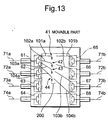
Fig. 13 is a schematic view showing the
constitution of the optical cross-connecting system as the
optical switch system of an eighth embodiment of the
present invention. As shown in Fig. 13, the same
constituting components as those of the fifth and seventh
embodiments are denoted with the same reference numerals.
The optical cross-connecting system of the eighth
embodiment is different from that of the seventh embodiment
in that instead of the array type space optical switch
using the interrupting plate in the seventh embodiment, the
array type space optical switch of the fifth embodiment
using the EDFA gate parts formed on the ends of the optical
fibers is disposed. The respects different from the fifth
and seventh embodiments will mainly be described
hereinafter.
-
As shown in Fig. 13, in the optical cross-connecting
system of the eighth embodiment, the input light
to the inputting optical fiber 71a is branched by the
optical separator 61 into the light transmission path
constituted of the optical fibers 101a and 101b, the light
transmission path constituted of the optical fibers 103a
and 103b, and the light transmission path constituted of
the optical fibers 104a and 104b. The array type space
optical switch is inserted to these light transmission
paths. In the same manner as the third embodiment, the
array type space optical switch is constituted of the space
propagation part 200 between two optical fibers in each set
of optical fibers, and the movable parts 41 to 44 disposed
on the ends of the optical fibers 101a to 104a on the side
of the space propagation part 200.
-
Each end of the optical fibers 101a to 104a on the
opposite side of the space propagation part 200 is
connected to the optical separator 61. The end of the
optical fiber 101b on the opposite side of the space
propagation part 200 is connected to the optical combiner
65, and the end of the optical fiber 102b on the opposite
side of the space propagation part 200 is connected to the
optical combiner 66. Moreover, the end of the optical
fiber 103b on the opposite side of the space propagation
part 200 is connected to the optical combiner 67, and the
end of the optical fiber 104b on the opposite side of the
space propagation part 200 is connected to the optical
combiner 68.
-
The optical cross-connecting system of the eight
embodiment is provided with four 4 × 4 array type space
optical switches constituted as described above. The array
type space optical switches correspond to the inputting
optical fibers 71a to 74a, respectively. In Fig. 13, only
the array type space optical switch corresponding to the
optical separator 61 is shown. Also in the optical cross-connecting
system of the eight embodiment, in the same
manner as the fifth embodiment, the photonic switching is
performed by moving the ends of the optical fibers to
control the optical space coupling between the optical
fibers.
-
In the optical cross-connecting system of the
eighth embodiment, the signal light of 1550 nm band is
inputted from each end surface of the inputting optical
fibers 71a to 74a on the opposite side of the optical
separator. For example, when the signal light inputted to
the inputting optical fiber 71a is outputted from the
outputting optical fiber 73b, the moving means is used to
move the movable parts 41, 42, 44, and the optical coupling
of the optical fibers 101a and 101b, optical coupling of
the optical fibers 102a and 102b, and optical coupling of
the optical fibers 104a and 104b are released. In this
case, the light inputted to the inputting optical fiber 71a
is separated to the light transmission paths 101a to 104a
via the optical separator 61, but by releasing the optical
coupling by the movable parts 41, 42, 44 as described above,
the outputs of the signal lights from the optical fibers
101a, 102a, 104a are interrupted. Additionally, the state
is switched to the state in which the signal light from the
optical fiber 103a is outputted to the optical fiber 103b
via the space propagation part 200. The light inputted to
the optical fiber 103b from the optical fiber 103a is
outputted to the outputting optical fiber 73b via the
optical combiner 67.
-
In this operation, three movable parts 41, 42, 44
are controlled. However, in the same manner as in the
fifth embodiment, by using appropriate moving means for
moving the movable parts 41 to 44, a plurality of movable
parts can simultaneously be controlled with one switch
driving. Therefore, when the movable parts 41 to 44 are
controlled by the control means, the light can be taken out
of the arbitrary light output port in the optical cross-connecting
system of the eighth embodiment. Moreover, even
in the light transmission path between the optical
separator 62 and each of the optical combiners 65 to 68,
light transmission path between the optical separator 63
and each of the optical combiners 65 to 68, and light
transmission path between the optical separator 64 and each
of the optical combiners 65 to 68, by connecting the light
input and output ports with the constitution similar to the
light transmission path between the optical separator 61
and each of the optical combiners 65 to 68, the matrix type
optical switch can be realized so that the light
transmission path can be switched with one switch driving.
(Ninth Embodiment)
-
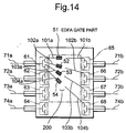
Fig. 14 is a schematic view showing the
constitution of the optical cross-connecting system as the
optical switch system of a ninth embodiment of the present
invention. In Fig. 14, the same constituting components as
those of the sixth and eighth embodiments are denoted with
the same reference numerals. For the optical cross-connecting
system of the ninth embodiment, in the optical
cross-connecting system of the eight embodiment, instead of
the array type space optical switch of the fifth embodiment,
the array type space optical switch of the sixth embodiment
is used. Therefore, the optical cross-connecting system of
the ninth embodiment is different from that of the eight
embodiment in that the photonic switching is performed
using the EDFA gate parts formed on the ends of the optical
fibers, instead of moving the end of the optical fiber in
the optical switch between the optical separator and the
optical combiner. The respects different from the sixth
and eighth embodiments will mainly be described hereinafter.
-
As shown in Fig. 14, in the optical cross-connecting
system of the ninth embodiment, similarly to the
sixth embodiment, the EDFA gate part 51 is formed in the
part of the optical fiber 101a adjacent to the space
propagation part 200, and the EDFA gate part 52 is formed
in the part of the optical fiber 102a adjacent to the space
propagation part 200. Moreover, the EDFA gate part 53 is
formed in the part of the optical fiber 103a adjacent to
the space propagation part 200, and the EDFA gate part 54
is formed in the part of the optical fiber 104a adjacent to
the space propagation part 200. Even in the optical cross-connecting
system of the ninth embodiment, the EDFA gate
parts 51 to 54 are utilized as the optical switches, and by
controlling the intensity of pumping light injected to each
of the EDFA gate parts 51 to 54, the turning on/off of the
light emitted from the EDFA gate part is controlled.
-
In the optical cross-connecting system of the
ninth embodiment, the signal light of 1550 nm band is
inputted from the end surface of each of the inputting
optical fibers 71a to 74a on the opposite side of the
optical separator. For example, when the signal light
inputted to the inputting optical fiber 71a is outputted
from the outputting optical fiber 73b, the pumping lights
to the EDFA gate parts 51, 52, 54 are interrupted from the
state in which the pumping lights are inputted to the EDFA
gate parts 51 to 54. In this case, the light inputted to
the inputting optical fiber 71a is separated to the light
transmission paths 101a to 104a via the optical separator
61, but by interrupting the pumping lights to the EDFA gate
parts 51, 52, 54, the signal lights inputted to the optical
fibers 101a, 102a, 104a are interrupted by the EDFA gate
parts 51, 52, 54. Additionally, the state is switched to
the state in which the signal light from the optical fiber
103a is outputted to the optical fiber 103b via the space
propagation part 200. The light inputted to the optical
fiber 103b from the optical fiber 103a is outputted to the
outputting optical fiber 73b via the optical combiner 67.
-
In this operation, three EDFA gate parts 51, 52,
54 are controlled. A plurality of EDFA gate parts can
simultaneously be controlled with one control to emit the
pumping lights by using the control means provided with the
appropriate pumping light transmitting means. Therefore,
when the control means is used to control the EDFA gate
parts 51 to 54, the light can be taken out of the arbitrary
light output port in the array type space optical switch of
the ninth embodiment. Moreover, even in the light
transmission path between the optical separator 62 and each
of the optical combiners 65 to 68, light transmission path
between the optical separator 63 and each of the optical
combiners 65 to 68, and light transmission path between the
optical separator 64 and each of the optical combiners 65
to 68, by connecting the light input and output ports with
the constitution similar to that of the light transmission
path between the optical separator 61 and each of the
optical combiners 65 to 68, the matrix type optical switch
can be realized so that the light transmission path can be
switched with one switch driving.
(Tenth Embodiment)
-
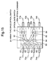
Fig. 15 is a schematic view showing the
constitution of the optical cross-connecting system as the
optical switch system of a tenth embodiment of the present
invention. In Fig. 15, the same constituting components as
those of the seventh embodiment are denoted with the same
reference numerals. The optical cross-connecting system of
the ninth embodiment is different from the seventh
embodiment in the array type space optical switch and the
optical combiner. The optical combiner of the tenth
embodiment is provided with an optical gate switch. The
respects different from the seventh embodiment will mainly
be described.
-
As shown in Fig. 15, the optical cross-connecting
system of the tenth embodiment is provided with array type
space optical switches 91 , 92, 93, 94. The array type
space optical switch 91 performs the photonic switching in
the light transmission path between each of the optical
separators 61, 62 and the outputting optical fiber 71b, and
the array type space optical switch 92 performs the
photonic switching in the light transmission path between
each of the optical separators 63, 64 and the outputting
optical fiber 71b. The array type space optical switch 93
performs the photonic switching in the light transmission
path between each of the optical separators 61, 62 and the
outputting optical fiber 73b. The array type space optical
switch 94 performs the photonic switching in the light
transmission path between each of the optical separators 63,
64 and the outputting optical fiber 73b. Each of the array
type space optical switches 91 to 94 is a 2 × 2 array type
space optical switch which has two light input ports and
two light output ports.
-
Each of the array type space optical switches 91
to 94 has a constitution similar to that of either one of
the array type space optical switch using the interrupting
plate as in the first embodiment, the array type space
optical switch for moving the optical fiber end as in the
fifth embodiment, and the array type space optical switch
using the EDFA gate part as in the sixth embodiment. Even
when either one is used, the photonic switching is
simultaneously performed in two light transmission paths
with one switching operation in these array type space
optical switches 91 to 94.
-
Moreover, the optical cross-connecting system of
the tenth embodiment is provided with an optical combiner
65a as an optical coupler for coupling four light
transmission paths extended from the light output ports of
the array type space optical switches 91, 92 into one, and
an optical combiner 66a as the optical coupler for coupling
four light transmission paths extended from the light
output ports of the array type space optical switches 93,
94 into one. The optical combiner 65a is provided with
optical gate switches 81, 82, and the optical combiner 66a
is provided with optical gate switches 83, 84.
-
One of four light output ports of the optical
separator 61 on the opposite side of the inputting optical
fiber 71a is connected to one light input port of the array
type space optical switch 91 via the optical fiber, and the
other one of the four light output ports of the optical
separator 61 is connected to one light input port of the
array type space optical switch 93 via the optical fiber.
One of four light output ports of the optical separator 62
on the opposite side of the inputting optical fiber 72a is
connected to the other light input port of the array type
space optical switch 91 via the optical fiber, and the
other one of the four light output ports of the optical
separator 62 is connected to the other light input port of
the array type space optical switch 93 via the optical
fiber.
-
One of four light output ports of the optical
separator 63 on the opposite side of the inputting optical
fiber 73a is connected to one light input port of the array
type space optical switch 92 via the optical fiber, and the
other one of the four light output ports of the optical
separator 63 is connected to one light input port of the
array type space optical switch 94 via the optical fiber.
One of four light output ports of the optical separator 64
on the opposite side of the inputting optical fiber 74a is
connected to the other light input port of the array type
space optical switch 92 via the optical fiber, and the
other one of the four light output ports of the optical
separator 64 is connected to the other light input port of
the array type space optical switch 94 via the optical
fiber.
-
The optical combiner 65a couples the light passed
from the inputting optical fiber 71a via the optical
separator 61 and the array type space optical switch 91,
the light passed from the inputting optical fiber 72a via
the optical separator 62 and the array type space optical
switch 91, the light passed from the inputting optical
fiber 73a via the optical separator 63 and the array type
space optical switch 92, and the light passed from the
inputting optical fiber 74a via the optical separator 64
and the array type space optical switch 92. The light
coupled by the optical combiner 65a is outputted to the
outputting optical fiber 71b. Moreover, the optical
combiner 66a couples the light passed from the inputting
optical fiber 71a via the optical separator 61 and the
array type space optical switch 93, the light passed from
the inputting optical fiber 72a via the optical separator
62 and the array type space optical switch 93, the light
passed from the inputting optical fiber 73a via the optical
separator 63 and the array type space optical switch 94,
and the light passed from the inputting optical fiber 74a
via the optical separator 64 and the array type space
optical switch 94. The light coupled by the optical
combiner 66a is outputted to the outputting optical fiber
73b.
-
The optical gate switch 81 disposed on the optical
combiner 65a performs the photonic switching of the light
obtained by coupling the light transmitted from the
inputting optical fiber 71a via the optical separator 61
and array type space optical switch 91 and the light
transmitted from the inputting optical fiber 73a via the
optical separator 63 and the array type space optical
switch 92. The optical gate switch 82 performs the
photonic switching of the light obtained by coupling the
light transmitted from the inputting optical fiber 72a via
the optical separator 62 and array type space optical
switch 91 and the light transmitted from the inputting
optical fiber 74a via the optical separator 64 and the
array type space optical switch 92.
-
The optical gate switch 83 disposed on the optical
combiner 66a performs the photonic switching of the light
obtained by coupling the light transmitted from the
inputting optical fiber 71a via the optical separator 61
and array type space optical switch 93 and the light
transmitted from the inputting optical fiber 73a via the
optical separator 63 and the array type space optical
switch 94. The optical gate switch 84 performs the
photonic switching of the light obtained by coupling the
light transmitted from the inputting optical fiber 72a via
the optical separator 62 and array type space optical
switch 93 and the light transmitted from the inputting
optical fiber 74a via the optical separator 64 and the
array type space optical switch 94.
-
Similarly to the light transmission paths between
each of the inputting optical fibers 71a to 74a and the
outputting optical fibers 71b, 73b, the light transmission
path between each of the inputting optical fibers 71a to
74a and the outputting optical fiber 72b, and the light
transmission path between each of the inputting optical
fibers 71a to 74a and the outputting optical fiber 74b are
constituted of the optical separators 61 to 64, array type
space optical switches, optical combiners provided with the
optical gate switches, and a plurality of optical fibers
for connecting these components.
-
In the optical cross-connecting system of the
tenth embodiment, the signal light of 1550 nm band is
inputted from each end surface of the inputting optical
fibers 71a to 74a on the opposite side of the optical
separator. For example, when the signal light inputted to
the inputting optical fiber 71a is outputted from the
outputting optical fiber 71b, the array type space optical
switch 91 is turned on, the array type space optical switch
92 is turned off, the optical gate switch 81 is turned on,
and the optical gate switch 82 is turned off. Thereby, the
inputting optical fiber 71a and the outputting optical
fiber 71b are optically coupled via the optical separator
61, array type space optical switch 91 and optical combiner
65a, and the light inputted to the inputting optical fiber
71a is outputted to the outputting optical fiber 71b
without mixing with the lights from the inputting optical
fibers 72a to 74a.
-
Similarly to the operation of the above-described
optical cross-connecting system, the complete driving of
the 4 × 4 matrix type optical switch is realized by
performing the switching operation of the array type space
optical switch and optical gate switch to the other light
input and output ports.
-
In the optical cross-connecting system of the
tenth embodiment, each optical combiner is provided with
the optical gate switch, but the optical cross-connecting
system which can perform the above-described switching
operation may be constituted by provided the optical
separator, not the optical combiner, with the optical gate
switch.
(Eleventh Embodiment)
-
Fig. 16 is a schematic view showing the
constitution of the optical cross-connecting system as the
optical switch system of an eleventh embodiment of the
present invention. The optical cross-connecting system of
the eleventh embodiment is an 8 × 8 matrix type optical
switch which has eight light input ports and eight light
output ports.
-
In the optical cross-connecting system of the
eleventh embodiment, as shown in Fig. 16, inputting optical
fibers 701 to 708 are attached to the light input ports.
Outputting optical fibers 711 to 718 are attached to the
light output ports. Each one end of the inputting optical
fibers 701 to 708 is connected to an optical separator 601
as an optical branch unit. For the inputting optical
fibers 701 to 708 the optical separator 601 branches the
light inputted to one of the inputting optical fibers 701
to 708 to eight transmission lines in correspondence with
the number of outputting optical fibers. In Fig. 16, a
part of the optical separator 601 corresponding to the
inputting optical fibers 701 to 708 is omitted.
-
Moreover, the optical cross-connecting system of
the eleventh embodiment is provided with array type space
optical switches 901, 902 for performing the photonic
switching in the light transmission path between the
optical separator 601 and the outputting optical fiber 711,
and array type space optical switches 903, 904 for
performing the photonic switching between the optical
separator 601 and the outputting optical fiber 712. Each
of the array type space optical switches 901 to 904 is a 4
× 4 array type space optical switch which has four light
input ports and four light output ports.
-
Each of the array type space optical switches 901
to 904 have constitutions which is similar to either one of
the constitutions of the array type space optical switch
using the interrupting plate as in the first embodiment,
the array type space optical switch for moving the optical
fiber end as in the fifth embodiment, and the array type
space optical switch using the EDFA gate part as in the
sixth embodiment. Even when either one is used, the
photonic switching is simultaneously performed in four
light transmission paths with one switching operation in
these array type space optical switches 901 to 904.
-
The light transmission paths are connected to the
light input ports of the array type space optical switch
901 from the inputting optical fibers 701 to 704 via the
optical separator 601, and the light transmission paths are
connected to the light input ports of the array type space
optical switch 902 from the inputting optical fibers 705 to
708 via the optical separator 601. The light transmission
paths are connected to the light input ports of the array
type space optical switch 903 from the inputting optical
fibers 701 to 704 via the optical separator 601, and the
light transmission paths are connected to the light input
ports of the array type space optical switch 904 from the
inputting optical fibers 705 to 708 via the optical
separator 601. The optical separator 601 is connected to
the array type space optical switches 901 to 904 via the
optical fibers.
-
The light output ports of the array type space
optical switches 901, 902 are connected to an optical
combiner 611 as an optical coupler via the optical fibers.
The light output ports of the array type space optical
switches 903, 904 are connected to an optical combiner 612
as the optical coupler via the optical fibers. The optical
combiner 611 combines the lights transmitted via the array
type space optical switches 901, 902 into one light, and
the light combined by the optical combiner 611 is outputted
to the outputting optical fiber 711. The optical combiner
612 combines the lights transmitted via the array type
space optical switches 903, 904 into one light, and the
light combined by the optical combiner 612 is outputted to
the outputting optical fiber 712.
-
The optical combiner 611 is provided with optical
gate switches 801 to 804, and the optical combiner 612 is
provided with optical gate switches 805 to 808. The
optical gate switch 801 performs the switching of the light
obtained by coupling the light transmitted from the
inputting optical fiber 701 via the optical separator 601
and the array type space optical switch 901 and the light
transmitted from the inputting optical fiber 705 via the
optical separator 601 and the array type space optical
switch 902. The optical gate switch 802 performs the
switching of the light obtained by coupling the light
transmitted from the inputting optical fiber 702 via the
optical separator 601 and the array type space optical
switch 901 and the light transmitted from the inputting
optical fiber 706 via the optical separator 601 and the
array type space optical switch 902. The optical gate
switch 803 performs the switching of the light obtained by
coupling the light transmitted from the inputting optical
fiber 703 via the optical separator 601 and the array type
space optical switch 901 and the light transmitted from the
inputting optical fiber 707 via the optical separator 601
and the array type space optical switch 902. The optical
gate switch 804 performs the switching of the light
obtained by coupling the light transmitted from the
inputting optical fiber 704 via the optical separator 601
and the array type space optical switch 901 and the light
transmitted from the inputting optical fiber 708 via the
optical separator 601 and the array type space optical
switch 902.
-
Moreover, the optical gate switch 805 performs the
switching of the light obtained by coupling the light
transmitted from the inputting optical fiber 701 via the
optical separator 601 and the array type space optical
switch 903 and the light transmitted from the inputting
optical fiber 705 via the optical separator 601 and the
array type space optical switch 904. The optical gate
switch 803 performs the switching of the light obtained by
coupling the light transmitted from the inputting optical
fiber 702 via the optical separator 601 and the array type
space optical switch 903 and the light transmitted from the
inputting optical fiber 706 via the optical separator 601
and the array type space optical switch 904. The optical
gate switch 807 performs the switching of the light
obtained by coupling the light transmitted from the
inputting optical fiber 703 via the optical separator 601
and the array type space optical switch 903 and the light
transmitted from the inputting optical fiber 707 via the
optical separator 601 and the array type space optical
switch 904. The optical gate switch 808 performs the
switching of the light obtained by coupling the light
transmitted from the inputting optical fiber 704 via the
optical separator 601 and the array type space optical
switch 903 and the light transmitted from the inputting
optical fiber 708 via the optical separator 601 and the
array type space optical switch 904.
-
Similarly to the light transmission paths between
each of the inputting optical fibers 701 to 708 and the
outputting optical fibers 711, 712, the light transmission
path between each of the inputting optical fibers 701 to
708 and each of the outputting optical fibers 713 to 718 is
constituted of the optical separator 61, 4 × 4 array type
space optical switch, optical combiner provided with the
optical gate switch, and a plurality of optical fibers for
connecting these components.
-
In the optical cross-connecting system of the
eleventh embodiment, the signal light of 1550 nm band is
inputted from each end surface of the inputting optical
fibers 701 to 708 on the opposite side of the optical
separator 601. For example, when the signal light inputted
to the inputting optical fiber 701 is outputted from the
outputting optical fiber 711, the array type space optical
switch 901 is turned on, the array type space optical
switch 902 is turned off, the optical gate switch 801 is
turned on, and the optical gate switches 802 to 804 are
turned off. Thereby, the inputting optical fiber 701 and
the outputting optical fiber 711 are optically coupled via
the optical separator 601, array type space optical switch
901 and optical combiner 611, and the light inputted to the
inputting optical fiber 701 is outputted to the outputting
optical fiber 711 without mixing with the lights from the
inputting optical fibers 702 to 708.
-
Similarly to the operation of the above-described
optical cross-connecting system, the complete driving of
the 4 × 4 matrix type optical switch is realized by
performing the switching operation of the array type space
optical switch and optical gate switch to the other light
input and output ports.
-
In the optical cross-connecting system of the
eleventh embodiment, the array type space optical switches
901, 902, and optical gate switches 801 to 804 are used in
the light transmission path between each of the inputting
optical fibers 701 to 708 and the outputting optical fiber
711. Six optical switches in total are used in the light
transmission path. Therefore, 6 × 8, that is, 48 optical
switches in total are used in the entire 8 × 8 optical
cross-connecting system. Different from this optical
cross-connecting system, the 8 × 8 optical crossbar switch
network as a conventional 8 × 8 optical cross-connecting
system requires 64 optical switches in total, and the
number of optical switches used in the optical cross-connecting
system of the eleventh embodiment is 3/4 of the
number of optical switches in the conventional 8 × 8
optical crossbar switch network. The effect that the
number of optical switches of the optical cross-connecting
system is reduced becomes more remarkable when the scale of
the optical cross-connecting system increases.
-
For example, when a 16 × 16 optical cross-connecting
system using 16 wavelengths is constituted with
the constitution similar to that of the light transmission
path between the inputting optical fiber and the outputting
optical fiber in the optical cross-connecting system of the
eleventh embodiment, the necessary number of optical
switches is 112 in total. On the other hand, when the 16 ×
16 optical cross-connecting system is prepared with the
constitution similar to that of the conventional optical
crossbar switch network, 256 optical switches are necessary.
Therefore, in the 16 × 16 system having the constitution
similar to that of the optical cross-connecting system of
the eleventh embodiment, the number of necessary optical
switches is reduced to 1/2 of the number of optical
switches in the conventional 16 × 16 optical crossbar
switch network. When the semiconductor optical amplifier
is used as the optical switch, the number of semiconductor
optical amplifiers is reduced to 1/2.
-
Therefore, the number of optical switches
necessary for the conventional matrix type optical switch
is the square of the number of light input ports, but by
constituting the matrix type optical switch with the
combination of the array type space optical switch and gate
switch, the number of necessary optical switches can
remarkably be reduced. Moreover, since the size of the
matrix type optical switch can be reduced by using the
constitution of the optical cross-connecting system of the
eleventh embodiment, the array type space optical switches
can be arrayed.
-
In the optical cross-connecting system of the
eleventh embodiment, each optical combiner is provided with
the optical gate switch. The optical cross-connecting
system which can perform the above-described switching
operation may be constituted by disposing the optical gate
switch on the optical separator 601, instead of the optical
combiner.
-
The above-described optical switch of the present
invention is not limited to the constitution of the array
type space optical switch in the above-described first to
sixth embodiments. Any other switch that has the
characteristics of the array type space optical switch of
each embodiment is included in the present invention, and
the basic principle of the optical switch of the present
invention can be utilized in various constitutions of array
type space optical switches.
-
The shape of the interrupting plate used in the
above-described embodiments is not limited to the shape
shown in Figs. 1, 3, 4, 5, 6 and 7. Any interrupting plate
can be used as long as it shields the arbitrary light path
for space propagation and it exerts no influence on the
light not interrupted in the space propagation part during
the shielding. Additionally, an optical shutter using a
liquid crystal may be used instead of the interrupting
plate.
-
Furthermore, when the end of the optical fiber is
moved, the moving method is not particularly limited. For
example, an electromagnetic system, an electric system, and
any other method can be utilized.
-
Additionally, any part that has the same operation
principle or function as that of the erbium-doped fiber
amplifier (EDFA) gate part can be used for the EDFA gate.
Moreover, the methods similar to the three methods of using
the interrupting plate, moving the optical fiber end, and
using the light amplifying or attenuating optical element,
and the array type space optical switch prepared by
combining these methods are also included in the present
invention.
-
Furthermore, the space propagation part is not
limited by the position of the interrupting plate, optical
fiber movable part, or EDFA gate. For example, it is also
possible to dispose a plurality of interrupting plates,
optical fiber movable parts, or EDFA gates in one space
propagation part.
-
Additionally, there are four light input ports and
four light output ports in each array type space optical
switch of the first to sixth embodiments, but the number of
ports is not limited to four, and the number can freely be
set to arbitrary numbers such as 8, 16, 32, 64. A
multiplicity of optical fibers can be switched altogether
by using the array type space optical switch.
-
Moreover, the input light wavelength is not
limited to 1550 nm band in each array type space optical
switch of the first to sixth embodiments. It can be set to
1300 nm band or the like, or it is also possible to
propagate the lights not only of one wavelength but also of
multiplexed wavelength. The light input direction is not
limited to either one direction. The light input and
output ports may be used in a mixed manner, or one port may
be used for both input and output.
-
Furthermore, the optical switch system of the
present invention is not limited to each optical cross-connecting
system of the seventh to eleventh embodiments,
the number of light input and output ports in the optical
cross-connecting system can freely be to set to the
arbitrary numbers such as 8, 16, 32, 64, and a multiplicity
of optical fibers can be switched at the same time by using
the optical cross-connecting system. Additionally, the
number of light input ports may be different from the
number of light output ports. For example, the number of
light input ports is n and the number of light output ports
is m, and the number of ports may be set to an arbitrary
integer. The array type space optical switch disposed in
the optical cross-connecting system can be replaced with
any switch of the above-described first to sixth
embodiments, and any other switch that has the same
principle or function as that of the array type space
optical switch.
-
Moreover, in order to compensate for the loss
during the branching of the light, the array type space
optical switch or the optical gate switch which has an
optical amplifying function can also be used. Furthermore,
in the optical cross-connecting system, the method of
branching the optical fiber and the number of wavelengths
to be controlled at the same time by the array type space
optical switch can freely be set to the methods and the
numbers other than those described in the above-described
embodiments.
-
Additionally, the wavelength of the input light is
not limited to the 1550 nm band in the optical cross-connecting
systems of the seventh to eleventh embodiments.
The 1300 nm or other bands can be used, or it is also
possible to propagate the lights not only of one wavelength
but also of multiplexed wavelength. The light input
direction is not limited to either one direction. The
light input and output ports may be used in a mixed manner,
or one port may be used for both input and output.
-
Moreover, for the optical separator and the
optical combiner used in each optical cross-connecting
system of the seventh to eleventh embodiments, ordinary
optical branching and coupling units can also be used, but
by using a single/multi-combiner having a function of
converting either one of the single mode and multi-mode of
the optical fiber to the other one, the loss during the
separating and combining of the light can be reduced. The
single/multi-combiner is one type of optical coupler. This
is prepared by bundling and fusing/connecting the vicinity
of the tip ends of a plurality of single mode optical
fibers to form one fused/connected multi-mode optical fiber.
-
According to the optical switch of the present
invention, the following effects are obtained.
Specifically, when the photonic switching is performed
between two optical fibers in each pair of optical fibers
among a plurality of pairs of optical fibers, the plurality
of pairs of optical fibers can be controlled to turn on or
off at the same time.
-
According to the optical switch system of the
present invention, the following effects are obtained.
Specifically, while the function completely equivalent to
that of the optical crossbar switch network as the
conventional optical cross-connecting system is provided,
the number of optical switches for use in the optical
switch system can be reduced. Therefore, the amount of
hardware of the optical switch is reduced, and the matrix
type optical switch small in size and low in cost can be
obtained.
-
While this invention has been described in
connection with certain preferred embodiments, it is to be
understood that the subject matter encompassed by way of
this invention is not to be limited to those specific
embodiments. On the contrary, it is intended for the
subject matter of the invention to include all alternative,
modification and equivalents as can be included within the
spirit and scope of the following claims.