EP1024002A2 - Ink jet print head - Google Patents
Ink jet print head Download PDFInfo
- Publication number
- EP1024002A2 EP1024002A2 EP00101495A EP00101495A EP1024002A2 EP 1024002 A2 EP1024002 A2 EP 1024002A2 EP 00101495 A EP00101495 A EP 00101495A EP 00101495 A EP00101495 A EP 00101495A EP 1024002 A2 EP1024002 A2 EP 1024002A2
- Authority
- EP
- European Patent Office
- Prior art keywords
- top plate
- ink
- print head
- heater board
- grooved top
- Prior art date
- Legal status (The legal status is an assumption and is not a legal conclusion. Google has not performed a legal analysis and makes no representation as to the accuracy of the status listed.)
- Withdrawn
Links
- 230000005484 gravity Effects 0.000 claims abstract description 32
- 238000003825 pressing Methods 0.000 claims abstract description 21
- 238000005304 joining Methods 0.000 claims abstract description 8
- 239000007788 liquid Substances 0.000 claims description 22
- 239000002184 metal Substances 0.000 claims description 6
- 229910052751 metal Inorganic materials 0.000 claims description 6
- 239000000976 ink Substances 0.000 description 88
- 238000010276 construction Methods 0.000 description 15
- 238000007639 printing Methods 0.000 description 15
- 230000000694 effects Effects 0.000 description 6
- 238000005516 engineering process Methods 0.000 description 6
- 238000010438 heat treatment Methods 0.000 description 4
- 238000005452 bending Methods 0.000 description 3
- 230000008901 benefit Effects 0.000 description 3
- 238000009835 boiling Methods 0.000 description 3
- 238000007641 inkjet printing Methods 0.000 description 3
- 239000000463 material Substances 0.000 description 3
- 230000008859 change Effects 0.000 description 2
- 239000003086 colorant Substances 0.000 description 2
- 238000000034 method Methods 0.000 description 2
- 230000004048 modification Effects 0.000 description 2
- 238000012986 modification Methods 0.000 description 2
- 238000000465 moulding Methods 0.000 description 2
- 239000011347 resin Substances 0.000 description 2
- 229920005989 resin Polymers 0.000 description 2
- 230000004044 response Effects 0.000 description 2
- 238000005549 size reduction Methods 0.000 description 2
- 239000007787 solid Substances 0.000 description 2
- 229910052782 aluminium Inorganic materials 0.000 description 1
- XAGFODPZIPBFFR-UHFFFAOYSA-N aluminium Chemical compound [Al] XAGFODPZIPBFFR-UHFFFAOYSA-N 0.000 description 1
- 230000005540 biological transmission Effects 0.000 description 1
- 238000004140 cleaning Methods 0.000 description 1
- 239000002131 composite material Substances 0.000 description 1
- 239000004020 conductor Substances 0.000 description 1
- 238000009826 distribution Methods 0.000 description 1
- 239000011521 glass Substances 0.000 description 1
- 230000017525 heat dissipation Effects 0.000 description 1
- 230000010365 information processing Effects 0.000 description 1
- 230000008569 process Effects 0.000 description 1
- 238000011084 recovery Methods 0.000 description 1
- 239000003566 sealing material Substances 0.000 description 1
- 229910052710 silicon Inorganic materials 0.000 description 1
- 239000010703 silicon Substances 0.000 description 1
- 230000000087 stabilizing effect Effects 0.000 description 1
- 238000009827 uniform distribution Methods 0.000 description 1
- 238000009834 vaporization Methods 0.000 description 1
- 230000008016 vaporization Effects 0.000 description 1
Images


Classifications
-
- B—PERFORMING OPERATIONS; TRANSPORTING
- B41—PRINTING; LINING MACHINES; TYPEWRITERS; STAMPS
- B41J—TYPEWRITERS; SELECTIVE PRINTING MECHANISMS, i.e. MECHANISMS PRINTING OTHERWISE THAN FROM A FORME; CORRECTION OF TYPOGRAPHICAL ERRORS
- B41J2/00—Typewriters or selective printing mechanisms characterised by the printing or marking process for which they are designed
- B41J2/005—Typewriters or selective printing mechanisms characterised by the printing or marking process for which they are designed characterised by bringing liquid or particles selectively into contact with a printing material
- B41J2/01—Ink jet
- B41J2/135—Nozzles
- B41J2/14—Structure thereof only for on-demand ink jet heads
- B41J2/14016—Structure of bubble jet print heads
- B41J2/14024—Assembling head parts
-
- B—PERFORMING OPERATIONS; TRANSPORTING
- B41—PRINTING; LINING MACHINES; TYPEWRITERS; STAMPS
- B41J—TYPEWRITERS; SELECTIVE PRINTING MECHANISMS, i.e. MECHANISMS PRINTING OTHERWISE THAN FROM A FORME; CORRECTION OF TYPOGRAPHICAL ERRORS
- B41J2/00—Typewriters or selective printing mechanisms characterised by the printing or marking process for which they are designed
- B41J2/005—Typewriters or selective printing mechanisms characterised by the printing or marking process for which they are designed characterised by bringing liquid or particles selectively into contact with a printing material
- B41J2/01—Ink jet
- B41J2/135—Nozzles
- B41J2/14—Structure thereof only for on-demand ink jet heads
- B41J2002/14362—Assembling elements of heads
Definitions
- the present invention relates to an ink jet print head in which ink paths for ejecting ink droplets are formed by joining together a grooved top plate and a heater board by a press member.
- An ink jet printing system is recognized as a very effective printing system because it performs non-impact printing that produces virtually no noise during printing, because it is capable of high speed printing and because it requires no special fixing of a printed image on plain paper as a recording medium.
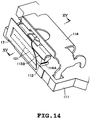
- Fig. 14 is a schematic perspective view showing an essential portion of a conventional ink jet print head disclosed in Japanese Patent Application Laid-Open No. 3-101957.
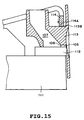
- Fig. 15 is a cross section taken along the line Y-Y of Fig. 14.
- reference number 112 represents a heater board having a plurality of electrothermal transducers (not shown) as a heat source.
- a grooved top plate 113 has integrally formed therein a plurality of ink orifices 101, grooved ink paths 105 communicating with the ink orifices 101, wall portions 106 forming ink paths walls, and a recessed portion as a common liquid chamber 107 for supplying ink to the ink paths 105.
- Denoted 111 is a base plate to support components.
- Designated 114 is a spring member that joins together the heater board 112 and the grooved top plate 113 by a pressing force to form the ink paths 105.
- the spring member 114 has a bent end portion 114A formed at its free end and presses it against a flat upper surface 113B of the top plate 113 to engage the top plate 113 with the heater board 112, with a pressing force of the spring member acting through a line contact. It has been a conventional practice to form the spring member 114 with the rigid bent end portion 114A and press the bent end portion 114A against the upper surface 113B of the top plate 113 to join the two members -- the top plate 113 and the heater board 112 -- with the pressing force.
- the ink jet printers of recent years have undergone price and size reductions and there is a corresponding increase in demand for a simplified structure of the ink jet print head.
- the size of the print head is basically determined by the size of the base plate 111 and thus it is effective in reducing the size of the head to eliminate, or reduce the size of, the base plate 111.
- the structure with the base plate 111 eliminated or reduced in size however, loses a heat dissipating function, one of the functions of the base plate 111, and thus requires some measures to suppress a temperature rise in the print head.
- Fig. 16 is an exploded perspective view of a conventional ink jet print head disclosed in the Japanese Patent Application Laid-Open No. 10-71715.
- the print head of Fig. 16 has an orifice plate 202 formed with a plurality of ink orifices 201, a grooved top plate 200 having ink paths 203 and a common liquid chamber 204 integrally formed therein, a heater board 210 connected with a printed circuit board 205, and a spring press member 220.
- this print head has the underside of the heater board 210 pressed by the spring press member 220 to bind the grooved top plate 200 and the heater board 210 together.
- the spring press member 220 is supported like a cantilever on a top plate mount (not shown) integrally formed with the grooved top plate 200.
- the spring press member 220 presses the back of the heater board 210 at a position close to where electrothermal transducers 211 are installed, at a contact angle ⁇ with a pressing force acting through a line contact, to ensure an intimate contact between the top plate 200 and the heater board 210. Further, in this print head, the spring press member 220 is made of a good thermal conductive material to release heat generated by the electrothermal transducers 211. The spring press member 220 is assigned a heat dissipating function of the base plate 111 of the prior art shown in Fig. 14.
- the heater board 210 of the conventional technology is pressed by a pressing force acting through a line contact despite the fact that the spring press member 220 has variations in its position and attitude caused by warping and bending of the top plate 200, the pressing force acting through a line contact is directly affected by the variations in position and attitude of the spring press member 220 and is likely to fluctuate or be unevenly distributed.
- the conventional technology therefore has a problem of not being able to bind the top plate 200 and the heater board 210 together with a uniform contact pressure with respect to the arrangement direction of ink paths 8.
- the present invention has been accomplished to solve the problem described above. It is therefore a primary object of the invention to provide an ink jet print head having a base plate eliminated or reduced in size in which the grooved top plate and the heater board are engaged together with a uniform pressure over their entire contact surface to securely hold them in close contact with each other.
- the ink jet print head comprises: a grooved top plate having a plurality of groove-like ink paths, a common liquid chamber for supplying ink to the plurality of ink paths and a plurality of orifices for ejecting ink; a heater board having a plurality of heat generating elements for generating an ink ejection pressure arranged at positions on a front surface thereof corresponding to the plurality of ink paths; and a press member for pressing and joining together the grooved top plate and the heater board; wherein the press member presses against a back of the heater board at the vicinity of a joint gravity center of the heater board and the grooved top plate.
- the press member presses against the back of the heater board at the vicinity of the joint gravity center of the heater board and the grooved top plate to bring the heater board and the grooved top plate into intimate contact with each other, it is possible to engage the heater board and the grooved top plate with a uniform pressure over their entire contact surface. This in turn enables the heater board and the grooved top plate to be intimately joined together for a long period of time. It is therefore possible to produce a stable ink ejection pressure in each ink path, thereby realizing a high quality printing.
- the plurality of projections formed on the press member are pressed against the back of the heater board at a plurality of points that are almost equal in position to the joint gravity center with respect to the longitudinal direction of the ink paths. This enables the heater board and the grooved top plate to be joined together with a uniform pressure over their entire contact surface even when the grooved top plate has warping or bending.
- the ink jet print head comprises: a grooved top plate having a plurality of groove-like ink paths, a common liquid chamber for supplying ink to the plurality of ink paths and a plurality of orifices for ejecting ink; a heater board having a plurality of heat generating elements for generating an ink ejection pressure arranged at positions on a front surface thereof corresponding to the plurality of ink paths; a press member for pressing and joining together the grooved top plate and the heater board; and a heat dissipating member arranged on a back of the heater board; wherein the press member presses against a back of the heat dissipating member at a position on the heat dissipating member corresponding to the vicinity of a joint gravity center of the heater board and the grooved top plate.
- the heat dissipating member with a large heat conductivity is placed on the back of the heater board, the heat dissipating performance of the heater board can be improved. Further, because the heat dissipating member is arranged on the back of the heater board, the press member presses the heater board through the heat dissipating member. The pressing position on the heat dissipating member is the joint gravity center of the grooved top plate and the heater board, as in the first aspect of the invention. Therefore, this second aspect of the invention also produces the similar effects to those of the first aspect of the invention, such as the ability to join the heater board and the grooved top plate together with a uniform pressure over their entire contact surface.
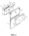
- Fig. 1 is an exploded perspective view showing an essential portion of the first embodiment of the ink jet print head according to the invention.
- Fig. 2 is a cross section of components of the print head assembled together.
- the print head of this embodiment has a grooved top plate 2, a heater board 3 and a press member 1, with the press member 1 pressing against the back of the heater board 3 to fixedly hold the heater board 3 and the grooved top plate 2 together.
- the grooved top plate 2 is formed of a molding resin material, glass or metal as one piece and has an orifice plate 6 formed with a row of ink orifices 7, a plurality of ink paths 8 in the form of grooves, a common liquid chamber 9 for supplying ink to the ink paths 8.
- the common liquid chamber 9 is connected to an ink tank unit not shown.
- a reference projection 11 is formed on the grooved top plate 2 at a position behind an upper surface wall of the common liquid chamber 9. The reference projection 11 is located at a central portion with respect to the arrangement direction of the ink paths 8.
- a plurality of electrothermal transducers 5 are arranged at positions corresponding to the ink paths 8.
- the rear end of the heater board 3 is connected to a printed circuit board 4 to supply a power supply voltage and electric signals such as drive signals to the electrothermal transducers 5.
- the press member 1 is a metal leaf spring with good thermal conductivity and is supported like a cantilever on a top plate mount 20 formed integral with the grooved top plate 2, as shown in Fig. 2.
- the press member 1 has, in this case, two projections A at predetermined positions in an area opposing the heater board 3.
- the two projections A though shown in Fig. 3 as half-globes, may be of any shape as long as they can make a point contact. For example, they may take a pointed shape.
- a front part of the grooved top plate 2 i.e., a portion where the ink paths 8 are formed, can be brought into secure engagement with the heater board 3 with a uniform contact pressure with respect to the arrangement direction of the ink paths 8 even when there is warping or dimensional variation of components such as top plate 2.
- a gap between the grooved top plate 2 and the heater board 3 is sealed with an appropriate sealing material when they are joined.
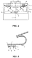
- Fig. 4 is a plan view of the essential portion of the grooved top plate 2 as seen from an arrow H of Fig. 2.
- the projections A formed in the press member 1 are located where they can press the vicinity of a gravity center of the grooved top plate 2 and the heater board 3 joined together. Pressing the gravity center of the joined members causes the heater board 3 and the grooved top plate 2 to engage each other with a uniform pressure over their entire contact surface. That is, both the top surface of the ink paths 8 of the grooved top plate 2 and the frame portion of the top plate forming the common liquid chamber 9 are reliably pressed.
- a triangle is formed by connecting the outermost ends of a line segment L2, which connects a plurality of longitudinal centers, with respect to the front and rear direction (longitudinal direction), of the ink paths 8, and the center of the reference projection 11. Then a center of gravity G0 of this triangle is determined and defined as a gravity center G0 of the joined members or a joint gravity center G0.
- Fig. 4 shows only two points to be the joint gravity centers, four or six points or even greater numbers of points may be used as long as they are located the same distances on the left and right side from the center line L1. It is of course possible to arrange the projections A to press the joint gravity center G0.
- the thermal energy to eject ink is generated by electrothermal transducers 5 on the heater board 3 and a part of the generated heat is transmitted to the ink which is then expelled out of the print head through the ink orifices 7. The remaining heat is transmitted to the press member 1 situated on the back of the heater board 3, from which the heat is dissipated.
- the heater board 3 is pressed from the back at the vicinity of the joint gravity centers of the heater board 3 and the grooved top plate 2 to bring the heater board 3 and the grooved top plate 2 into intimate contact with each other.
- This allows the heater board 3 and the grooved top plate 2 to be reliably held against each other with a uniform pressure over their entire contact surface, which in turn ensures the intimate contact between the heater board 3 and the grooved top plate 2 for a long period of time. It is therefore possible to obtain stable ejection pressure in the individual ink paths 8, realizing high quality printing.
- the heater board 3 is pressed by a force acting through a point contact of the projections A as shown in Fig. 5, rather than through a line contact, the severity with which the pressing condition of the heater board 3 is directly affected by any warping or distortion of the members making up the grooved top plate 2 and by the resulting shift of the press member 1 from its normal position and angle can be alleviated. It is therefore possible to reduce fluctuating and uneven distributions of the pressure with which the heater board 3 is pressed, compared with those in the conventional print head. This enables the top plate 2 and the heater board 3 to be engaged together with a more uniform distribution of contact pressure.
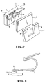
- Figs. 6 and 7 are exploded perspective views showing the construction of the second embodiment of the ink jet print head according to the invention.
- constitutional elements identical with the corresponding elements in the first embodiment are assigned like reference numbers and their explanations are omitted.
- a feature of the second embodiment is that a slit 1a is formed in the press member 1 at its central portion between the projections A to divide the front end side of the press member 1 into a plurality of front end blocks like a comb. Because the heater board 3 is pressed independently by the individual projections A provided in each of the front end blocks divided by the slit 1a, the press member 1 can follow the surface contour of the back of the heater board 3 more easily than in the first embodiment as it is pressed against the heater board 3, even when the heater board 3 is warped. Hence, the intimate contact between the grooved top plate 2 and the heater board 3 can be improved. In this case, as the number of the divided front end blocks increases, the contact between the top plate 2 and the heater board 3 becomes more intimate.
- An ink jet print head with a plurality of liquid chambers 9 as shown in Fig. 7 can also produce the similar effect.
- Fig. 8 shows a construction in which a heat dissipating member 10 of, for example, aluminum with good thermal conductivity is provided between the press member 1 and the heater board 3 to further improve the heat dissipating capability of the press member 1.
- the pressing positions of the projections A are located at the joint gravity centers of the grooved top plate 2 and the heater board 3.
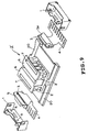
- Fig. 9 is an exploded perspective view of the third embodiment of the ink jet print head.
- Fig. 10 is an enlarged schematic cross section showing an essential portion of the print head of Fig. 9.
- a small base plate 3a as a heat dissipating member is provided on the back of the heater board 3 so that the press member 1 presses the heater board 3 through the small base plate 3a.
- the press member 1 has a plurality of projections A as in the previous embodiments, which are pressed against the small base plate 3a at positions corresponding to the joint gravity centers of the grooved top plate 2 and the heater board 3.
- a grooved top plate module 2' has a pair of grooved top plates 2 formed integrally on the top plate mount 20 to form two print heads, each having a row of ink orifices. There are also a pair of the heater board 3 and the press member 1. A pair of grooved top plates 2 are disposed such that a groove-forming portion of each said grooved top plate 2 is oriented outwardly.
- the press members 1 are each fixedly supported on the top plate mount 20 of the grooved top plate module 2' as in the previous embodiments.
- the provision of the small base plate 3a as a heat dissipating member with high thermal conductivity on the back of the heater board 3 improves the heat dissipating performance over the previous embodiments. Because the small base plate 3a is arranged on the back of the heater board 3, the press member 1 presses the heater board 3 through the small base plate 3a, with the pressing positions set at the joint gravity centers of the grooved top plate 2 and the heater board 3 as in the previous embodiments. Therefore, the similar effects to those of the previous embodiments can be produced, which include an advantage that the heater board 3 and the grooved top plate 2 can be held against each other with a uniform pressure over their entire contact surface.
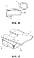
- Fig. 11 shows the fourth embodiment of the invention.
- the fourth embodiment is characterized in that the front end portion of the press member 1 is rounded as indicated at R and that the rounded end portion of the press member 1 is pressed, through the small base plate 3a, against the heater board 3 in the vicinity of the joint gravity centers of the grooved top plate 2 and the heater board 3.
- This embodiment is achieved by taking into consideration the heat dissipation from the head and the fact that the press member 1 is formed of a plate material, such as a metal plate, and offers an advantage that the shape of the press member 1 is simplified by rounding the pressing portion of the press member 1.
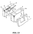
- Figs. 12 and 13 show the fifth embodiment of the invention.
- the fifth embodiment is characterized in that the front end portion of the press member 1 is divided into two or more parts by a slit 1a as in the second embodiment.
- the grooved top plate 2 has a plurality of divided liquid chambers 9.
- This embodiment is intended to deal with a situation in which the small base plate 3a, when it is thin, may be deformed by the warped heater board 3. That is, the front end portion of the press member 1 is divided by the slit 1a into a plurality of front end blocks corresponding to the projections A, and the individual projections A provided one on each front end block independently press the heater board 3. Hence, the individual projections A can be pressed against the small base plate 3a following the warped surface contour of the small base plate 3a, improving the contact state of the grooved top plate 2 and the heater board 3.
- this invention produces an excellent effect particularly in the print head and printing apparatus of a type which has a means to generate thermal energy for ejecting ink (e.g., electrothermal transducer and laser beam) and causes a status change in ink by the thermal energy. This is because this type of print head and printing apparatus can realize higher recording density and higher resolution.
- thermal energy for ejecting ink e.g., electrothermal transducer and laser beam
- this type of printing system preferably use a fundamental principle disclosed in U.S. Patent Nos. 4,723,129 and 4,740,796. While this type of printing system is applicable to both the so-called on-demand type and the continuous type, it is particularly effectively applied to the on-demand type because the electrothermal transducer arranged in correspondence with a sheet or path containing liquid (ink) is applied at least one drive signal, which corresponds to print information and causes a rapid temperature rise in excess of a nucleate boiling, to generate thermal energy in the electrothermal transducer and cause a film boiling on the heat acting surface of the print head, thereby forming a bubble in ink that has a one-to-one correspondence to the drive signal.
- the electrothermal transducer arranged in correspondence with a sheet or path containing liquid (ink) is applied at least one drive signal, which corresponds to print information and causes a rapid temperature rise in excess of a nucleate boiling, to generate thermal energy in the electrothermal transducer and cause a film boiling on the heat acting
- the growth and collapse of the bubble expels ink out of the orifice to form at least one drop of ink.
- the drive signal should preferably be in the form of pulse because the growth and collapse of the bubbles can be achieved instantaneously and appropriately, assuring the ejection of liquid (ink) with good response.
- Suitable pulse drive signals are those described in the U.S. Patent Nos. 4,463,359 and 4,345,262. Better printing can be realized by using the conditions described in U.S. Patent No. 4,313,124 related to the rate of increase of temperature on the heat acting surface.
- this invention includes a construction in which the heat acting portion is located in a bent area, as disclosed in U.S. Patent Nos. 4,558,333 and 4,459,600.
- the present invention is also suited to the print heads that employ a construction in which a common slit is used as the orifice portion for a plurality of electrothermal transducers, as disclosed in Japanese Patent Application Laid-Open No. 59-123670, and a construction in which an opening for absorbing the pressure wave of thermal energy is used as the orifice portion, as disclosed in Japanese Patent Application Laid-Open No. 59-138461. That is, this invention ensures reliable and effective printing whatever form the print head may take.
- this invention can suitably be applied to a print head of full line type which has a length corresponding to the maximum recordable width of a recording medium.
- a print head may have a construction in which a plurality of print heads are combined to meet the required print length or a construction of a one-piece print head.
- serial type print heads for which this invention is effective, include a print head fixed to the printer body, a replaceable chip type print head that is mounted to the printer body for electrical connection to and ink supply from the printer body, and a cartridge type print head that is integrally provided with an ink tank.
- an ink ejection performance recovery means and other auxiliary means for the print head may be provided in the printing apparatus of this invention. These are preferable as they contribute to further stabilizing the effects of this invention.
- auxiliary means may include a capping means, a cleaning means, a pressurization or suction means, an electrothermal transducer or heating element different from the electrothermal transducer or a preliminary heating means combining the electrothermal transducer and the heating element, and a preliminary ink ejection means for ejecting ink for other than printing, all for the print head.
- this invention is particularly effective for the printing apparatus that uses at least one of the following print modes, whether the print head is a single one-piece print head or a combination of two or more print heads: a single color print mode with a mainstream color such as black, a composite color print mode using different colors and a full color print mode based on color mixing.
- ink as liquid
- ink jet system the ink is generally temperature-controlled in the range of 30-70°C to control the ink viscosity in a stable ejection range
- ink that liquefies when a print signal is applied it is also possible to use an ink that liquefies when a print signal is applied.
- an ink that solidifies on standing and liquefies on heating may be used.
- this invention is also applicable where an ink used has a property of being liquefied only when it is given thermal energy.
- Example applications include one in which the ink is liquefied by the application of thermal energy in response to the print signal before being ejected and one in which the ink is made to start solidifying before it arrives at the recording medium.
- the ink used in these applications may be arranged as described in Japanese Patent Application Laid-Open No. 54-56847 or 60-71260, in which the ink in a liquid or solid state held in recesses or through holes in a porous sheet is opposed to the electrothermal transducers.
- the print system of this invention that is most suited for the above-described inks is the one that executes the film boiling method.
- the ink jet printing apparatus of this invention may be implemented in the form of a copying machine combined with a reader and a facsimile having a transmission/reception function, as well as in the form of an image output terminal for information processing equipment such as computer.
- the pressing portion of the press member (1) for joining the top plate (2) and the heater board (3) together is formed into projections A, which are pressed against the back of the heater board (3) at the vicinity of the joint gravity center of the top plate (2) and the heater board (3) to firmly join the top plate (2) and the heater board (3) with a uniform pressure over their entire contact surface.
Abstract
Description
- The present invention relates to an ink jet print head in which ink paths for ejecting ink droplets are formed by joining together a grooved top plate and a heater board by a press member.
- An ink jet printing system is recognized as a very effective printing system because it performs non-impact printing that produces virtually no noise during printing, because it is capable of high speed printing and because it requires no special fixing of a printed image on plain paper as a recording medium.
- Fig. 14 is a schematic perspective view showing an essential portion of a conventional ink jet print head disclosed in Japanese Patent Application Laid-Open No. 3-101957. Fig. 15 is a cross section taken along the line Y-Y of Fig. 14.
- In Figs. 14 and 15,
reference number 112 represents a heater board having a plurality of electrothermal transducers (not shown) as a heat source. A groovedtop plate 113 has integrally formed therein a plurality ofink orifices 101, groovedink paths 105 communicating with theink orifices 101,wall portions 106 forming ink paths walls, and a recessed portion as a commonliquid chamber 107 for supplying ink to theink paths 105. Denoted 111 is a base plate to support components. Designated 114 is a spring member that joins together theheater board 112 and the groovedtop plate 113 by a pressing force to form theink paths 105. - The
spring member 114 has abent end portion 114A formed at its free end and presses it against a flatupper surface 113B of thetop plate 113 to engage thetop plate 113 with theheater board 112, with a pressing force of the spring member acting through a line contact. It has been a conventional practice to form thespring member 114 with the rigidbent end portion 114A and press thebent end portion 114A against theupper surface 113B of thetop plate 113 to join the two members -- thetop plate 113 and theheater board 112 -- with the pressing force. - The ink jet printers of recent years have undergone price and size reductions and there is a corresponding increase in demand for a simplified structure of the ink jet print head. In a print head structure in which the
top plate 113 is joined to theheater board 112 fixedly mounted on thebase plate 111, the size of the print head is basically determined by the size of thebase plate 111 and thus it is effective in reducing the size of the head to eliminate, or reduce the size of, thebase plate 111. The structure with thebase plate 111 eliminated or reduced in size, however, loses a heat dissipating function, one of the functions of thebase plate 111, and thus requires some measures to suppress a temperature rise in the print head. - The official gazette of Japanese Patent Application Laid-Open No. 10-71715 discloses a technology in which the base plate is either eliminated or reduced in size to achieve a size reduction of the print head and also suppress a temperature rise in the print head.
- Fig. 16 is an exploded perspective view of a conventional ink jet print head disclosed in the Japanese Patent Application Laid-Open No. 10-71715.
- The print head of Fig. 16 has an
orifice plate 202 formed with a plurality ofink orifices 201, a groovedtop plate 200 havingink paths 203 and a commonliquid chamber 204 integrally formed therein, aheater board 210 connected with a printedcircuit board 205, and aspring press member 220. Instead of pressing the upper surface of thetop plate 200 as in the preceding conventional art, this print head has the underside of theheater board 210 pressed by thespring press member 220 to bind thegrooved top plate 200 and theheater board 210 together. Thespring press member 220 is supported like a cantilever on a top plate mount (not shown) integrally formed with the groovedtop plate 200. - In this print head, as shown in Fig. 17, the
spring press member 220 presses the back of theheater board 210 at a position close to whereelectrothermal transducers 211 are installed, at a contact angle with a pressing force acting through a line contact, to ensure an intimate contact between thetop plate 200 and theheater board 210. Further, in this print head, thespring press member 220 is made of a good thermal conductive material to release heat generated by theelectrothermal transducers 211. Thespring press member 220 is assigned a heat dissipating function of thebase plate 111 of the prior art shown in Fig. 14. - (1) In the conventional technology, however,
because the
spring press member 220 presses, at a contact angle , a vicinity of the front edge of theheater board 210 close to where theelectrothermal transducers 211 are installed as shown in Fig. 17, moments of force B and C as shown in Fig. 17 are generated. Hence, with this conventional technology the rear end of theheater board 210 tends to float from the groovedtop plate 200. This makes the contact between them unstable. - (2) The grooved
top plate 200 is made of a molding resin material and can easily produce warping and bending. As described earlier, thespring press member 220 is supported on the top plate mount formed integral with the groovedtop plate 200, so that when thetop plate 200 is warped or bent, thespring press member 220 is shifted from its normal support position and support angle. As a result, the position and angle of the pressing portion of thespring press member 220 are deviated. -
- Because the
heater board 210 of the conventional technology is pressed by a pressing force acting through a line contact despite the fact that thespring press member 220 has variations in its position and attitude caused by warping and bending of thetop plate 200, the pressing force acting through a line contact is directly affected by the variations in position and attitude of thespring press member 220 and is likely to fluctuate or be unevenly distributed. The conventional technology therefore has a problem of not being able to bind thetop plate 200 and theheater board 210 together with a uniform contact pressure with respect to the arrangement direction ofink paths 8. - The present invention has been accomplished to solve the problem described above. It is therefore a primary object of the invention to provide an ink jet print head having a base plate eliminated or reduced in size in which the grooved top plate and the heater board are engaged together with a uniform pressure over their entire contact surface to securely hold them in close contact with each other.
- It is another object of the invention to provide an ink jet print head capable of dissipating heat with an improved efficiency.
- According to a first aspect of the present invention, the ink jet print head comprises: a grooved top plate having a plurality of groove-like ink paths, a common liquid chamber for supplying ink to the plurality of ink paths and a plurality of orifices for ejecting ink; a heater board having a plurality of heat generating elements for generating an ink ejection pressure arranged at positions on a front surface thereof corresponding to the plurality of ink paths; and a press member for pressing and joining together the grooved top plate and the heater board; wherein the press member presses against a back of the heater board at the vicinity of a joint gravity center of the heater board and the grooved top plate.
- With this invention, because the press member presses against the back of the heater board at the vicinity of the joint gravity center of the heater board and the grooved top plate to bring the heater board and the grooved top plate into intimate contact with each other, it is possible to engage the heater board and the grooved top plate with a uniform pressure over their entire contact surface. This in turn enables the heater board and the grooved top plate to be intimately joined together for a long period of time. It is therefore possible to produce a stable ink ejection pressure in each ink path, thereby realizing a high quality printing.
- In this invention, the plurality of projections formed on the press member are pressed against the back of the heater board at a plurality of points that are almost equal in position to the joint gravity center with respect to the longitudinal direction of the ink paths. This enables the heater board and the grooved top plate to be joined together with a uniform pressure over their entire contact surface even when the grooved top plate has warping or bending.
- According to a second aspect of the present invention, the ink jet print head comprises: a grooved top plate having a plurality of groove-like ink paths, a common liquid chamber for supplying ink to the plurality of ink paths and a plurality of orifices for ejecting ink; a heater board having a plurality of heat generating elements for generating an ink ejection pressure arranged at positions on a front surface thereof corresponding to the plurality of ink paths; a press member for pressing and joining together the grooved top plate and the heater board; and a heat dissipating member arranged on a back of the heater board; wherein the press member presses against a back of the heat dissipating member at a position on the heat dissipating member corresponding to the vicinity of a joint gravity center of the heater board and the grooved top plate.
- Because the heat dissipating member with a large heat conductivity is placed on the back of the heater board, the heat dissipating performance of the heater board can be improved. Further, because the heat dissipating member is arranged on the back of the heater board, the press member presses the heater board through the heat dissipating member. The pressing position on the heat dissipating member is the joint gravity center of the grooved top plate and the heater board, as in the first aspect of the invention. Therefore, this second aspect of the invention also produces the similar effects to those of the first aspect of the invention, such as the ability to join the heater board and the grooved top plate together with a uniform pressure over their entire contact surface.
- The above and other objects, effects, features and advantages of the present invention will become more apparent from the following description of embodiments thereof taken in conjunction with the accompanying drawings.
- Fig. 1 is an exploded perspective view showing an essential portion of a first embodiment of the ink jet print head according to the invention;
- Fig. 2 is a schematic cross section of an essential portion of the ink jet print head of Fig. 1 cut in a direction crossing an orifice plate;
- Fig. 3 is a cross section of a projection of the press member;
- Fig. 4 is a plan view showing a center of gravity of joined members;
- Fig. 5 is an enlarged cross section showing how the press member engages the heater board in the first embodiment of the invention;
- Fig. 6 is an exploded perspective view showing a second embodiment of the invention;
- Fig. 7 is an exploded perspective view showing a variation of the second embodiment of the invention;
- Fig. 8 is a schematic cross section showing the construction of the variation with a heat dissipating member added;
- Fig. 9 is an exploded perspective view showing the construction of a third embodiment of the invention;
- Fig. 10 is an enlarged schematic cross section showing an essential portion of the third embodiment of the print head;
- Fig. 11 is a schematic cross section showing the construction of a fourth embodiment of the invention;
- Fig. 12 is a schematic perspective view showing the construction of a fifth embodiment of the invention;
- Fig. 13 is an exploded perspective view showing a variation of the fifth embodiment of the invention;
- Fig. 14 is a schematic perspective view showing a conventional ink jet print head;
- Fig. 15 is a cross section taken along the line Y-Y of Fig. 14;
- Fig. 16 is an exploded perspective view schematically showing another conventional ink jet print head; and
- Fig. 17 is a schematic view showing a drawback of the conventional technology.
-
- Now, embodiments of the present invention will be described by referring to the accompanying drawings.
- The first embodiment of the invention will be explained by referring to Figs. 1 to 4.
- Fig. 1 is an exploded perspective view showing an essential portion of the first embodiment of the ink jet print head according to the invention. Fig. 2 is a cross section of components of the print head assembled together.
- As shown in Figs. 1 and 2, the print head of this embodiment has a grooved
top plate 2, aheater board 3 and apress member 1, with thepress member 1 pressing against the back of theheater board 3 to fixedly hold theheater board 3 and the groovedtop plate 2 together. - The grooved
top plate 2 is formed of a molding resin material, glass or metal as one piece and has anorifice plate 6 formed with a row ofink orifices 7, a plurality ofink paths 8 in the form of grooves, acommon liquid chamber 9 for supplying ink to theink paths 8. Thecommon liquid chamber 9 is connected to an ink tank unit not shown. Areference projection 11 is formed on the groovedtop plate 2 at a position behind an upper surface wall of thecommon liquid chamber 9. Thereference projection 11 is located at a central portion with respect to the arrangement direction of theink paths 8. - On the surface of the
heater board 3 formed of silicon or the like (which faces the top plate 2) a plurality of electrothermal transducers 5 (see Fig. 2) are arranged at positions corresponding to theink paths 8. The rear end of theheater board 3 is connected to a printedcircuit board 4 to supply a power supply voltage and electric signals such as drive signals to theelectrothermal transducers 5. - The
press member 1 is a metal leaf spring with good thermal conductivity and is supported like a cantilever on atop plate mount 20 formed integral with the groovedtop plate 2, as shown in Fig. 2. Thepress member 1 has, in this case, two projections A at predetermined positions in an area opposing theheater board 3. The two projections A, though shown in Fig. 3 as half-globes, may be of any shape as long as they can make a point contact. For example, they may take a pointed shape. - When the
heater board 3 is joined to the groovedtop plate 2, because a rear part of that surface of the groovedtop plate 2 facing theheater board 3 contacts theheater board 3 through one point of thereference projection 11 arranged at the lateral center of that surface to receive a stress produced when the two members are pressed together, a front part of the groovedtop plate 2, i.e., a portion where theink paths 8 are formed, can be brought into secure engagement with theheater board 3 with a uniform contact pressure with respect to the arrangement direction of theink paths 8 even when there is warping or dimensional variation of components such astop plate 2. A gap between the groovedtop plate 2 and theheater board 3 is sealed with an appropriate sealing material when they are joined. - Next, by referring to Fig. 4, the positions of the projections A on the
press member 1 will be explained. Fig. 4 is a plan view of the essential portion of the groovedtop plate 2 as seen from an arrow H of Fig. 2. - The projections A formed in the
press member 1 are located where they can press the vicinity of a gravity center of the groovedtop plate 2 and theheater board 3 joined together. Pressing the gravity center of the joined members causes theheater board 3 and the groovedtop plate 2 to engage each other with a uniform pressure over their entire contact surface. That is, both the top surface of theink paths 8 of the groovedtop plate 2 and the frame portion of the top plate forming thecommon liquid chamber 9 are reliably pressed. - Now, the gravity center of the joined members will be explained below.
- As shown in Fig. 4, a triangle is formed by connecting the outermost ends of a line segment L2, which connects a plurality of longitudinal centers, with respect to the front and rear direction (longitudinal direction), of the
ink paths 8, and the center of thereference projection 11. Then a center of gravity G0 of this triangle is determined and defined as a gravity center G0 of the joined members or a joint gravity center G0. - It is, however, difficult to pinpoint and press the joint gravity center G0 as a two-dimensional coordinate by the
press member 1 during the joining process. In this embodiment, therefore, two points G1, G2, which are on a line segment L4 passing through the gravity center G0 parallelly to the line segment L2 and which are predetermined distances (L5 = L6), on the left and right side, from a center line L1 of the groovedtop plate 2 that passes through the center of thereference projection 11, are taken as joint gravity centers. - Although Fig. 4 shows only two points to be the joint gravity centers, four or six points or even greater numbers of points may be used as long as they are located the same distances on the left and right side from the center line L1. It is of course possible to arrange the projections A to press the joint gravity center G0.
- Next, the thermal conductivity in the print head will be explained.
- The thermal energy to eject ink is generated by
electrothermal transducers 5 on theheater board 3 and a part of the generated heat is transmitted to the ink which is then expelled out of the print head through theink orifices 7. The remaining heat is transmitted to thepress member 1 situated on the back of theheater board 3, from which the heat is dissipated. - In this embodiment, as shown in Fig. 5, the
heater board 3 is pressed from the back at the vicinity of the joint gravity centers of theheater board 3 and the groovedtop plate 2 to bring theheater board 3 and the groovedtop plate 2 into intimate contact with each other. This allows theheater board 3 and the groovedtop plate 2 to be reliably held against each other with a uniform pressure over their entire contact surface, which in turn ensures the intimate contact between theheater board 3 and the groovedtop plate 2 for a long period of time. It is therefore possible to obtain stable ejection pressure in theindividual ink paths 8, realizing high quality printing. - Further, in this embodiment, because the
heater board 3 is pressed by a force acting through a point contact of the projections A as shown in Fig. 5, rather than through a line contact, the severity with which the pressing condition of theheater board 3 is directly affected by any warping or distortion of the members making up the groovedtop plate 2 and by the resulting shift of thepress member 1 from its normal position and angle can be alleviated. It is therefore possible to reduce fluctuating and uneven distributions of the pressure with which theheater board 3 is pressed, compared with those in the conventional print head. This enables thetop plate 2 and theheater board 3 to be engaged together with a more uniform distribution of contact pressure. - Figs. 6 and 7 are exploded perspective views showing the construction of the second embodiment of the ink jet print head according to the invention. In this embodiment constitutional elements identical with the corresponding elements in the first embodiment are assigned like reference numbers and their explanations are omitted.
- A feature of the second embodiment is that a
slit 1a is formed in thepress member 1 at its central portion between the projections A to divide the front end side of thepress member 1 into a plurality of front end blocks like a comb. Because theheater board 3 is pressed independently by the individual projections A provided in each of the front end blocks divided by theslit 1a, thepress member 1 can follow the surface contour of the back of theheater board 3 more easily than in the first embodiment as it is pressed against theheater board 3, even when theheater board 3 is warped. Hence, the intimate contact between the groovedtop plate 2 and theheater board 3 can be improved. In this case, as the number of the divided front end blocks increases, the contact between thetop plate 2 and theheater board 3 becomes more intimate. - An ink jet print head with a plurality of
liquid chambers 9 as shown in Fig. 7 can also produce the similar effect. - Fig. 8 shows a construction in which a
heat dissipating member 10 of, for example, aluminum with good thermal conductivity is provided between thepress member 1 and theheater board 3 to further improve the heat dissipating capability of thepress member 1. The pressing positions of the projections A are located at the joint gravity centers of the groovedtop plate 2 and theheater board 3. - The third embodiment of the invention will be described by referring to Figs. 9 and 10. Fig. 9 is an exploded perspective view of the third embodiment of the ink jet print head. Fig. 10 is an enlarged schematic cross section showing an essential portion of the print head of Fig. 9.
- In the third embodiment, a
small base plate 3a as a heat dissipating member is provided on the back of theheater board 3 so that thepress member 1 presses theheater board 3 through thesmall base plate 3a. Thepress member 1 has a plurality of projections A as in the previous embodiments, which are pressed against thesmall base plate 3a at positions corresponding to the joint gravity centers of the groovedtop plate 2 and theheater board 3. - As shown in Fig. 9, a grooved top plate module 2' has a pair of grooved
top plates 2 formed integrally on thetop plate mount 20 to form two print heads, each having a row of ink orifices. There are also a pair of theheater board 3 and thepress member 1. A pair of groovedtop plates 2 are disposed such that a groove-forming portion of each said groovedtop plate 2 is oriented outwardly. - The
press members 1 are each fixedly supported on thetop plate mount 20 of the grooved top plate module 2' as in the previous embodiments. - In this embodiment, the provision of the
small base plate 3a as a heat dissipating member with high thermal conductivity on the back of theheater board 3 improves the heat dissipating performance over the previous embodiments. Because thesmall base plate 3a is arranged on the back of theheater board 3, thepress member 1 presses theheater board 3 through thesmall base plate 3a, with the pressing positions set at the joint gravity centers of the groovedtop plate 2 and theheater board 3 as in the previous embodiments. Therefore, the similar effects to those of the previous embodiments can be produced, which include an advantage that theheater board 3 and the groovedtop plate 2 can be held against each other with a uniform pressure over their entire contact surface. - Fig. 11 shows the fourth embodiment of the invention.
- In a construction in which the
heater board 3 with thesmall base plate 3a used in the third embodiment and the groovedtop plate 2 are joined together by thepress member 1, the fourth embodiment is characterized in that the front end portion of thepress member 1 is rounded as indicated at R and that the rounded end portion of thepress member 1 is pressed, through thesmall base plate 3a, against theheater board 3 in the vicinity of the joint gravity centers of the groovedtop plate 2 and theheater board 3. - This embodiment is achieved by taking into consideration the heat dissipation from the head and the fact that the
press member 1 is formed of a plate material, such as a metal plate, and offers an advantage that the shape of thepress member 1 is simplified by rounding the pressing portion of thepress member 1. - Figs. 12 and 13 show the fifth embodiment of the invention.
- In a construction in which the
heater board 3 with thesmall base plate 3a used in the third and fourth embodiments and the groovedtop plate 2 are joined together by the press member, the fifth embodiment is characterized in that the front end portion of thepress member 1 is divided into two or more parts by aslit 1a as in the second embodiment. In the case of Fig. 13, the groovedtop plate 2 has a plurality of dividedliquid chambers 9. - This embodiment is intended to deal with a situation in which the
small base plate 3a, when it is thin, may be deformed by thewarped heater board 3. That is, the front end portion of thepress member 1 is divided by theslit 1a into a plurality of front end blocks corresponding to the projections A, and the individual projections A provided one on each front end block independently press theheater board 3. Hence, the individual projections A can be pressed against thesmall base plate 3a following the warped surface contour of thesmall base plate 3a, improving the contact state of the groovedtop plate 2 and theheater board 3. - In the ink jet printing system, this invention produces an excellent effect particularly in the print head and printing apparatus of a type which has a means to generate thermal energy for ejecting ink (e.g., electrothermal transducer and laser beam) and causes a status change in ink by the thermal energy. This is because this type of print head and printing apparatus can realize higher recording density and higher resolution.
- As for the representative construction and working principle, this type of printing system preferably use a fundamental principle disclosed in U.S. Patent Nos. 4,723,129 and 4,740,796. While this type of printing system is applicable to both the so-called on-demand type and the continuous type, it is particularly effectively applied to the on-demand type because the electrothermal transducer arranged in correspondence with a sheet or path containing liquid (ink) is applied at least one drive signal, which corresponds to print information and causes a rapid temperature rise in excess of a nucleate boiling, to generate thermal energy in the electrothermal transducer and cause a film boiling on the heat acting surface of the print head, thereby forming a bubble in ink that has a one-to-one correspondence to the drive signal. The growth and collapse of the bubble expels ink out of the orifice to form at least one drop of ink. The drive signal should preferably be in the form of pulse because the growth and collapse of the bubbles can be achieved instantaneously and appropriately, assuring the ejection of liquid (ink) with good response. Suitable pulse drive signals are those described in the U.S. Patent Nos. 4,463,359 and 4,345,262. Better printing can be realized by using the conditions described in U.S. Patent No. 4,313,124 related to the rate of increase of temperature on the heat acting surface.
- In addition to the print head construction in which orifices, liquid paths (linear liquid paths or right-angle liquid paths) and electrothermal transducers are combined as disclosed in the specifications mentioned above, this invention includes a construction in which the heat acting portion is located in a bent area, as disclosed in U.S. Patent Nos. 4,558,333 and 4,459,600. The present invention is also suited to the print heads that employ a construction in which a common slit is used as the orifice portion for a plurality of electrothermal transducers, as disclosed in Japanese Patent Application Laid-Open No. 59-123670, and a construction in which an opening for absorbing the pressure wave of thermal energy is used as the orifice portion, as disclosed in Japanese Patent Application Laid-Open No. 59-138461. That is, this invention ensures reliable and effective printing whatever form the print head may take.
- Further, this invention can suitably be applied to a print head of full line type which has a length corresponding to the maximum recordable width of a recording medium. Such a print head may have a construction in which a plurality of print heads are combined to meet the required print length or a construction of a one-piece print head.
- These serial type print heads, for which this invention is effective, include a print head fixed to the printer body, a replaceable chip type print head that is mounted to the printer body for electrical connection to and ink supply from the printer body, and a cartridge type print head that is integrally provided with an ink tank.
- Further, an ink ejection performance recovery means and other auxiliary means for the print head may be provided in the printing apparatus of this invention. These are preferable as they contribute to further stabilizing the effects of this invention. Such auxiliary means may include a capping means, a cleaning means, a pressurization or suction means, an electrothermal transducer or heating element different from the electrothermal transducer or a preliminary heating means combining the electrothermal transducer and the heating element, and a preliminary ink ejection means for ejecting ink for other than printing, all for the print head.
- As to the kind and the number of print heads mounted, it is possible to use only one print head for a single color ink or a plurality of print heads for different colors and densities. That is, this invention is particularly effective for the printing apparatus that uses at least one of the following print modes, whether the print head is a single one-piece print head or a combination of two or more print heads: a single color print mode with a mainstream color such as black, a composite color print mode using different colors and a full color print mode based on color mixing.
- In addition, although the above embodiments have described ink as liquid, it is possible to use an ink that solidifies at room temperature or lower and softens or liquefies at room temperature. Because in the ink jet system the ink is generally temperature-controlled in the range of 30-70°C to control the ink viscosity in a stable ejection range, it is also possible to use an ink that liquefies when a print signal is applied. Further, to positively prevent a temperature rise due to thermal energy by consuming the thermal energy as an energy required to cause a status change in ink from solid to liquid state, or to prevent the vaporization of ink, an ink that solidifies on standing and liquefies on heating may be used. In either case, this invention is also applicable where an ink used has a property of being liquefied only when it is given thermal energy. Example applications include one in which the ink is liquefied by the application of thermal energy in response to the print signal before being ejected and one in which the ink is made to start solidifying before it arrives at the recording medium. The ink used in these applications may be arranged as described in Japanese Patent Application Laid-Open No. 54-56847 or 60-71260, in which the ink in a liquid or solid state held in recesses or through holes in a porous sheet is opposed to the electrothermal transducers. The print system of this invention that is most suited for the above-described inks is the one that executes the film boiling method.
- The ink jet printing apparatus of this invention may be implemented in the form of a copying machine combined with a reader and a facsimile having a transmission/reception function, as well as in the form of an image output terminal for information processing equipment such as computer.
- The present invention has been described in detail with respect to preferred embodiments, and it will now be apparent from the foregoing to those skilled in the art that changes and modifications may be made without departing from the invention in its broader aspect, and it is the invention, therefore, in the apparent claims to cover all such changes and modifications as fall within the true spirit of the invention.
- The pressing portion of the press member (1) for joining the top plate (2) and the heater board (3) together is formed into projections A, which are pressed against the back of the heater board (3) at the vicinity of the joint gravity center of the top plate (2) and the heater board (3) to firmly join the top plate (2) and the heater board (3) with a uniform pressure over their entire contact surface.
Claims (18)
- An ink jet print head characterized by comprising:a grooved top plate module formed with a grooved top plate having a plurality of groove-like ink paths, a common liquid chamber for supplying ink to the plurality of ink paths and a plurality of orifices for ejecting ink;a heater board having a plurality of heat generating elements for generating an ink ejection pressure arranged on a front surface of the heater board corresponding to the plurality of ink paths; anda press member for pressing and joining together the grooved top plate and the heater board;
wherein the press member presses against a back of the heater board at the vicinity of a joint gravity center of the heater board and the grooved top plate. - An ink jet print head according to claim 1, characterized in that said grooved top plate module a pair of grooved top plates disposed such that a groove-forming portion of each said grooved top plate is oriented outwardly, and a pair of the heater boards and the press members are provided.
- An ink jet print head according to claim 1, characterized in that the grooved top plate has a reference projection on a surface thereof facing the heater board at a position which is on a side of the common liquid chamber opposite the plurality of the ink paths and which is at the center of the surface with respect to the direction of arrangement of the plurality of the orifices.
- An ink jet print head according to claim 3, characterized in that the joint gravity center is a center of gravity of a triangle, the triangle being formed by connecting end points of a line segment connecting longitudinal centers of the plurality of ink paths and an arrangement position of the reference projection.
- An ink jet print head according to claim 1, characterized in that the press member presses against a plurality of points that are equal in position to the joint gravity center with respect to the longitudinal direction of the ink paths.
- An ink jet print head according to claim 5, characterized in that the press member has a plurality of projections that are pressed against a back of the heater board.
- An ink jet print head according to claim 6, characterized in that the plurality of projections are arranged in a direction almost parallel to the arrangement direction of the plurality of orifices.
- An ink jet print head according to claim 1, characterized in that the press member is made of a metal.
- An ink jet print head according to claim 1, characterized in that the press member is formed of a cantilever metal leaf spring, supported on the grooved top plate module.
- An ink jet print head according to claim 6, characterized in that the plurality of projections are spherical.
- An ink jet print head characterized by comprising:a grooved top plate module formed with grooved top plate having a plurality of groove-like ink paths, a common liquid chamber for supplying ink to the plurality of ink paths and a plurality of orifices for ejecting ink;a heater board having a plurality of heat generating elements for generating an ink ejection pressure arranged on a front surface of the heater board corresponding to the plurality of ink paths;a press member for pressing and joining together the grooved top plate and the heater board; anda heat dissipating member arranged on a back of the heater board;
wherein the press member presses against a back of the heat dissipating member at a position on the heat dissipating member corresponding to the vicinity of a joint gravity center of the heater board and the grooved top plate. - An ink jet print head according to claim 11, characterized in that said grooved top plate module a pair of grooved top plates disposed such that a groove-forming portion of each said grooved top plate is oriented outwardly, and a pair of the heater boards and the press members are provided.
- An ink jet print head according to claim 11, characterized in that the grooved top plate has a reference projection on a surface thereof facing the heater board at a position which is on a side of the common liquid chamber opposite the plurality of the ink paths and which is at the center of the surface with respect to the direction of arrangement of the plurality of the orifices.
- An ink jet print head according to claim 13, characterized in that the joint gravity center is a center of gravity of a triangle, the triangle being formed by connecting end points of a line segment connecting longitudinal centers of the plurality of ink paths and an arrangement position of the reference projection.
- An ink jet print head according to claim 11, characterized in that the press member presses against a plurality of points that are equal in position to the joint gravity center with respect to the longitudinal direction of the ink paths.
- An ink jet print head according to claim 15 characterized in that the press member has a plurality of projections that are pressed against a back of the heat dissipating member.
- An ink jet print head according to claim 16, characterized in that the plurality of projections are arranged in a direction almost parallel to the arrangement direction of the plurality of orifices.
- An ink jet print head according to claim 11, characterized in that the press member is formed of a cantilever metal leaf spring, supported on the grooved top plate module.
Applications Claiming Priority (2)
| Application Number | Priority Date | Filing Date | Title |
|---|---|---|---|
| JP1898499 | 1999-01-27 | ||
| JP11018984A JP2000211140A (en) | 1999-01-27 | 1999-01-27 | Ink jet recording head |
Publications (2)
| Publication Number | Publication Date |
|---|---|
| EP1024002A2 true EP1024002A2 (en) | 2000-08-02 |
| EP1024002A3 EP1024002A3 (en) | 2000-12-06 |
Family
ID=11986869
Family Applications (1)
| Application Number | Title | Priority Date | Filing Date |
|---|---|---|---|
| EP00101495A Withdrawn EP1024002A3 (en) | 1999-01-27 | 2000-01-26 | Ink jet print head |
Country Status (3)
| Country | Link |
|---|---|
| US (1) | US6394574B1 (en) |
| EP (1) | EP1024002A3 (en) |
| JP (1) | JP2000211140A (en) |
Families Citing this family (1)
| Publication number | Priority date | Publication date | Assignee | Title |
|---|---|---|---|---|
| JP2018091247A (en) * | 2016-12-05 | 2018-06-14 | 日本電産コパル電子株式会社 | Blower |
Citations (7)
| Publication number | Priority date | Publication date | Assignee | Title |
|---|---|---|---|---|
| US4313124A (en) | 1979-05-18 | 1982-01-26 | Canon Kabushiki Kaisha | Liquid jet recording process and liquid jet recording head |
| US4345262A (en) | 1979-02-19 | 1982-08-17 | Canon Kabushiki Kaisha | Ink jet recording method |
| US4463359A (en) | 1979-04-02 | 1984-07-31 | Canon Kabushiki Kaisha | Droplet generating method and apparatus thereof |
| US4558333A (en) | 1981-07-09 | 1985-12-10 | Canon Kabushiki Kaisha | Liquid jet recording head |
| US4723129A (en) | 1977-10-03 | 1988-02-02 | Canon Kabushiki Kaisha | Bubble jet recording method and apparatus in which a heating element generates bubbles in a liquid flow path to project droplets |
| JPH03101957A (en) | 1989-09-18 | 1991-04-26 | Canon Inc | Ink jet head, ink jet cartridge with the head, and ink jet recorder with the cartridge loaded thereon |
| JPH1071715A (en) | 1996-08-30 | 1998-03-17 | Canon Inc | Ink jet recording head |
Family Cites Families (11)
| Publication number | Priority date | Publication date | Assignee | Title |
|---|---|---|---|---|
| JPS5936879B2 (en) | 1977-10-14 | 1984-09-06 | キヤノン株式会社 | Thermal transfer recording medium |
| US4330787A (en) | 1978-10-31 | 1982-05-18 | Canon Kabushiki Kaisha | Liquid jet recording device |
| JPS59123670A (en) | 1982-12-28 | 1984-07-17 | Canon Inc | Ink jet head |
| JPS59138461A (en) | 1983-01-28 | 1984-08-08 | Canon Inc | Liquid jet recording apparatus |
| JPS6071260A (en) | 1983-09-28 | 1985-04-23 | Erumu:Kk | Recorder |
| DE69033722T2 (en) | 1989-09-18 | 2001-08-30 | Canon Kk | Inkjet device |
| CA2025561C (en) | 1989-09-18 | 1995-07-11 | Seiichiro Karita | Recording head with cover |
| US5341161A (en) * | 1991-06-14 | 1994-08-23 | Canon Kabushiki Kaisha | Ink recorder including a sealing member for an ink storage section |
| US5784079A (en) * | 1994-06-30 | 1998-07-21 | Canon Kabushiki Kaisha | Ink jet head and ink jet apparatus on which the ink jet head is mounted |
| US6084611A (en) * | 1995-10-16 | 2000-07-04 | Canon Kabushiki Kaisha | Recording head, having pressure-bonding member for binding recording element substrate and driving element substrate, head cartridge and recording apparatus having same |
| JPH09109394A (en) * | 1995-10-18 | 1997-04-28 | Canon Inc | Recording head |
-
1999
- 1999-01-27 JP JP11018984A patent/JP2000211140A/en active Pending
-
2000
- 2000-01-26 EP EP00101495A patent/EP1024002A3/en not_active Withdrawn
- 2000-01-27 US US09/491,866 patent/US6394574B1/en not_active Expired - Fee Related
Patent Citations (8)
| Publication number | Priority date | Publication date | Assignee | Title |
|---|---|---|---|---|
| US4723129A (en) | 1977-10-03 | 1988-02-02 | Canon Kabushiki Kaisha | Bubble jet recording method and apparatus in which a heating element generates bubbles in a liquid flow path to project droplets |
| US4740796A (en) | 1977-10-03 | 1988-04-26 | Canon Kabushiki Kaisha | Bubble jet recording method and apparatus in which a heating element generates bubbles in multiple liquid flow paths to project droplets |
| US4345262A (en) | 1979-02-19 | 1982-08-17 | Canon Kabushiki Kaisha | Ink jet recording method |
| US4463359A (en) | 1979-04-02 | 1984-07-31 | Canon Kabushiki Kaisha | Droplet generating method and apparatus thereof |
| US4313124A (en) | 1979-05-18 | 1982-01-26 | Canon Kabushiki Kaisha | Liquid jet recording process and liquid jet recording head |
| US4558333A (en) | 1981-07-09 | 1985-12-10 | Canon Kabushiki Kaisha | Liquid jet recording head |
| JPH03101957A (en) | 1989-09-18 | 1991-04-26 | Canon Inc | Ink jet head, ink jet cartridge with the head, and ink jet recorder with the cartridge loaded thereon |
| JPH1071715A (en) | 1996-08-30 | 1998-03-17 | Canon Inc | Ink jet recording head |
Also Published As
| Publication number | Publication date |
|---|---|
| JP2000211140A (en) | 2000-08-02 |
| EP1024002A3 (en) | 2000-12-06 |
| US6394574B1 (en) | 2002-05-28 |
Similar Documents
| Publication | Publication Date | Title |
|---|---|---|
| US5148192A (en) | Liquid jet recording head with nonlinear liquid passages and liquid jet recording apparatus having same | |
| US6135589A (en) | Ink jet recording head with ejection outlet forming member and urging member for assembling the head, and apparatus with such a head | |
| US8201925B2 (en) | Ink jet print head having board with varying heat resistance | |
| US6331039B1 (en) | Ink jet recording apparatus and method with modulatable driving pulse width | |
| JP2008036960A (en) | Inkjet recording head | |
| CA2557517A1 (en) | Droplet deposition apparatus | |
| EP0538021B1 (en) | Contact structure between flexible cable and signal receiving unit and recording apparatus using said contact structure | |
| US6394574B1 (en) | Ink jet print head having press member | |
| EP1043158B1 (en) | Ink jet recording head and ink jet recording apparatus | |
| EP0636478B1 (en) | Ink jet head, ink jet cartridge, and ink jet recording apparatus | |
| JP3826084B2 (en) | Liquid discharge head and image forming apparatus using the same | |
| JP3190454B2 (en) | Ink jet recording head and ink jet recording apparatus | |
| JP3313884B2 (en) | Inkjet recording method | |
| EP0694397A2 (en) | Ink jet head and ink jet apparatus on which the ink jet head is mounted | |
| JP3115755B2 (en) | Ink jet recording head, method of manufacturing the same, and ink jet recording apparatus | |
| JP4046970B2 (en) | Liquid discharge head, head cartridge, and image forming apparatus | |
| JP4454911B2 (en) | Liquid discharge head and image forming apparatus using the same | |
| JP3907685B2 (en) | Image forming apparatus | |
| JP2814330B2 (en) | Contact structure between flexible cable and signal receiving portion and recording apparatus using the contact structure | |
| JPH1071715A (en) | Ink jet recording head | |
| JP3683941B2 (en) | Ink jet head, ink jet cartridge having the head, and ink jet apparatus equipped with the head | |
| JPH07256882A (en) | Ink jet recording head, manufacture thereof and recorded with the recording head | |
| JP2959106B2 (en) | Inkjet head | |
| JPH0251735B2 (en) | ||
| JPH04305463A (en) | Electronic apparatus using ink jet recorder |
Legal Events
| Date | Code | Title | Description |
|---|---|---|---|
| PUAI | Public reference made under article 153(3) epc to a published international application that has entered the european phase |
Free format text: ORIGINAL CODE: 0009012 |
|
| AK | Designated contracting states |
Kind code of ref document: A2 Designated state(s): DE ES FR GB IT NL |
|
| AX | Request for extension of the european patent |
Free format text: AL;LT;LV;MK;RO;SI |
|
| PUAL | Search report despatched |
Free format text: ORIGINAL CODE: 0009013 |
|
| AK | Designated contracting states |
Kind code of ref document: A3 Designated state(s): DE ES FR GB IT NL |
|
| AX | Request for extension of the european patent |
Free format text: AL;LT;LV;MK;RO;SI |
|
| 17P | Request for examination filed |
Effective date: 20010411 |
|
| AKX | Designation fees paid |
Free format text: DE ES FR GB IT NL |
|
| 17Q | First examination report despatched |
Effective date: 20060619 |
|
| STAA | Information on the status of an ep patent application or granted ep patent |
Free format text: STATUS: THE APPLICATION HAS BEEN WITHDRAWN |
|
| 18W | Application withdrawn |
Effective date: 20061023 |