EP1022565A2 - Verfahren und Vorrichtung zum Entnehmen analytischer Verbrauchsmittel aus einem Vorratsbehältnis - Google Patents
Verfahren und Vorrichtung zum Entnehmen analytischer Verbrauchsmittel aus einem Vorratsbehältnis Download PDFInfo
- Publication number
- EP1022565A2 EP1022565A2 EP00100255A EP00100255A EP1022565A2 EP 1022565 A2 EP1022565 A2 EP 1022565A2 EP 00100255 A EP00100255 A EP 00100255A EP 00100255 A EP00100255 A EP 00100255A EP 1022565 A2 EP1022565 A2 EP 1022565A2
- Authority
- EP
- European Patent Office
- Prior art keywords
- plunger
- consumable
- feed
- transport
- control
- Prior art date
- Legal status (The legal status is an assumption and is not a legal conclusion. Google has not performed a legal analysis and makes no representation as to the accuracy of the status listed.)
- Granted
Links
- 238000000034 method Methods 0.000 title claims abstract description 10
- 238000012360 testing method Methods 0.000 claims abstract description 44
- 230000033001 locomotion Effects 0.000 claims abstract description 27
- 238000004458 analytical method Methods 0.000 claims abstract description 12
- 238000003780 insertion Methods 0.000 claims description 14
- 230000037431 insertion Effects 0.000 claims description 14
- 238000000605 extraction Methods 0.000 abstract 2
- 230000000149 penetrating effect Effects 0.000 abstract 1
- 238000005265 energy consumption Methods 0.000 description 9
- 230000001419 dependent effect Effects 0.000 description 7
- 239000000463 material Substances 0.000 description 6
- 230000008901 benefit Effects 0.000 description 5
- 239000011888 foil Substances 0.000 description 5
- 238000005259 measurement Methods 0.000 description 5
- 238000013461 design Methods 0.000 description 4
- 238000010586 diagram Methods 0.000 description 4
- 230000035515 penetration Effects 0.000 description 4
- 230000008569 process Effects 0.000 description 4
- 238000012549 training Methods 0.000 description 4
- 238000006073 displacement reaction Methods 0.000 description 3
- 238000007789 sealing Methods 0.000 description 3
- 229910000639 Spring steel Inorganic materials 0.000 description 2
- 230000033228 biological regulation Effects 0.000 description 2
- 230000005540 biological transmission Effects 0.000 description 2
- 230000008094 contradictory effect Effects 0.000 description 2
- 230000008878 coupling Effects 0.000 description 2
- 238000010168 coupling process Methods 0.000 description 2
- 238000005859 coupling reaction Methods 0.000 description 2
- 230000007423 decrease Effects 0.000 description 2
- 230000000694 effects Effects 0.000 description 2
- WQZGKKKJIJFFOK-GASJEMHNSA-N Glucose Natural products OC[C@H]1OC(O)[C@H](O)[C@@H](O)[C@@H]1O WQZGKKKJIJFFOK-GASJEMHNSA-N 0.000 description 1
- 206010036790 Productive cough Diseases 0.000 description 1
- 244000052616 bacterial pathogen Species 0.000 description 1
- 238000005452 bending Methods 0.000 description 1
- 238000012742 biochemical analysis Methods 0.000 description 1
- 230000015572 biosynthetic process Effects 0.000 description 1
- 239000008280 blood Substances 0.000 description 1
- 210000004369 blood Anatomy 0.000 description 1
- 239000003153 chemical reaction reagent Substances 0.000 description 1
- 230000000052 comparative effect Effects 0.000 description 1
- 230000006835 compression Effects 0.000 description 1
- 238000007906 compression Methods 0.000 description 1
- 238000010276 construction Methods 0.000 description 1
- 230000003247 decreasing effect Effects 0.000 description 1
- 230000006735 deficit Effects 0.000 description 1
- 239000002274 desiccant Substances 0.000 description 1
- 238000002405 diagnostic procedure Methods 0.000 description 1
- 239000000428 dust Substances 0.000 description 1
- 238000005516 engineering process Methods 0.000 description 1
- 230000007613 environmental effect Effects 0.000 description 1
- 238000011156 evaluation Methods 0.000 description 1
- 239000008103 glucose Substances 0.000 description 1
- 230000003993 interaction Effects 0.000 description 1
- 239000007788 liquid Substances 0.000 description 1
- 238000004519 manufacturing process Methods 0.000 description 1
- 230000009347 mechanical transmission Effects 0.000 description 1
- 230000004048 modification Effects 0.000 description 1
- 238000012986 modification Methods 0.000 description 1
- 230000003287 optical effect Effects 0.000 description 1
- 230000009467 reduction Effects 0.000 description 1
- 230000004044 response Effects 0.000 description 1
- 238000005070 sampling Methods 0.000 description 1
- 239000007787 solid Substances 0.000 description 1
- 239000000126 substance Substances 0.000 description 1
- 238000005353 urine analysis Methods 0.000 description 1
- 238000004804 winding Methods 0.000 description 1
Images


Classifications
-
- B—PERFORMING OPERATIONS; TRANSPORTING
- B01—PHYSICAL OR CHEMICAL PROCESSES OR APPARATUS IN GENERAL
- B01L—CHEMICAL OR PHYSICAL LABORATORY APPARATUS FOR GENERAL USE
- B01L99/00—Subject matter not provided for in other groups of this subclass
-
- G—PHYSICS
- G01—MEASURING; TESTING
- G01N—INVESTIGATING OR ANALYSING MATERIALS BY DETERMINING THEIR CHEMICAL OR PHYSICAL PROPERTIES
- G01N33/00—Investigating or analysing materials by specific methods not covered by groups G01N1/00 - G01N31/00
- G01N33/48—Biological material, e.g. blood, urine; Haemocytometers
- G01N33/483—Physical analysis of biological material
- G01N33/487—Physical analysis of biological material of liquid biological material
- G01N33/4875—Details of handling test elements, e.g. dispensing or storage, not specific to a particular test method
- G01N33/48757—Test elements dispensed from a stack
-
- G—PHYSICS
- G01—MEASURING; TESTING
- G01N—INVESTIGATING OR ANALYSING MATERIALS BY DETERMINING THEIR CHEMICAL OR PHYSICAL PROPERTIES
- G01N35/00—Automatic analysis not limited to methods or materials provided for in any single one of groups G01N1/00 - G01N33/00; Handling materials therefor
- G01N35/00029—Automatic analysis not limited to methods or materials provided for in any single one of groups G01N1/00 - G01N33/00; Handling materials therefor provided with flat sample substrates, e.g. slides
- G01N2035/00039—Transport arrangements specific to flat sample substrates, e.g. pusher blade
-
- G—PHYSICS
- G01—MEASURING; TESTING
- G01N—INVESTIGATING OR ANALYSING MATERIALS BY DETERMINING THEIR CHEMICAL OR PHYSICAL PROPERTIES
- G01N35/00—Automatic analysis not limited to methods or materials provided for in any single one of groups G01N1/00 - G01N33/00; Handling materials therefor
- G01N35/00029—Automatic analysis not limited to methods or materials provided for in any single one of groups G01N1/00 - G01N33/00; Handling materials therefor provided with flat sample substrates, e.g. slides
- G01N2035/00089—Magazines
-
- Y—GENERAL TAGGING OF NEW TECHNOLOGICAL DEVELOPMENTS; GENERAL TAGGING OF CROSS-SECTIONAL TECHNOLOGIES SPANNING OVER SEVERAL SECTIONS OF THE IPC; TECHNICAL SUBJECTS COVERED BY FORMER USPC CROSS-REFERENCE ART COLLECTIONS [XRACs] AND DIGESTS
- Y10—TECHNICAL SUBJECTS COVERED BY FORMER USPC
- Y10T—TECHNICAL SUBJECTS COVERED BY FORMER US CLASSIFICATION
- Y10T436/00—Chemistry: analytical and immunological testing
- Y10T436/11—Automated chemical analysis
- Y10T436/112499—Automated chemical analysis with sample on test slide
-
- Y—GENERAL TAGGING OF NEW TECHNOLOGICAL DEVELOPMENTS; GENERAL TAGGING OF CROSS-SECTIONAL TECHNOLOGIES SPANNING OVER SEVERAL SECTIONS OF THE IPC; TECHNICAL SUBJECTS COVERED BY FORMER USPC CROSS-REFERENCE ART COLLECTIONS [XRACs] AND DIGESTS
- Y10—TECHNICAL SUBJECTS COVERED BY FORMER USPC
- Y10T—TECHNICAL SUBJECTS COVERED BY FORMER US CLASSIFICATION
- Y10T436/00—Chemistry: analytical and immunological testing
- Y10T436/11—Automated chemical analysis
- Y10T436/113332—Automated chemical analysis with conveyance of sample along a test line in a container or rack
- Y10T436/114165—Automated chemical analysis with conveyance of sample along a test line in a container or rack with step of insertion or removal from test line
-
- Y—GENERAL TAGGING OF NEW TECHNOLOGICAL DEVELOPMENTS; GENERAL TAGGING OF CROSS-SECTIONAL TECHNOLOGIES SPANNING OVER SEVERAL SECTIONS OF THE IPC; TECHNICAL SUBJECTS COVERED BY FORMER USPC CROSS-REFERENCE ART COLLECTIONS [XRACs] AND DIGESTS
- Y10—TECHNICAL SUBJECTS COVERED BY FORMER USPC
- Y10T—TECHNICAL SUBJECTS COVERED BY FORMER US CLASSIFICATION
- Y10T436/00—Chemistry: analytical and immunological testing
- Y10T436/25—Chemistry: analytical and immunological testing including sample preparation
- Y10T436/2575—Volumetric liquid transfer
Definitions
- the invention relates to a device and a corresponding Method for removing an analytical consumable, especially a test element a storage container that has one or more chambers.
- the chambers each contain one or more Consumables and each have a removal opening for removing a consumable and one of the removal opening opposite insertion opening for insertion a pestle for the transport of the to be removed Consumable on.
- the removal opening and the insertion opening for storing the consumable with a film, also known as a sealing film is closed.
- a plunger is moved by means of a drive unit and the consumable through the plunger from the chamber transported out in the storage container.
- carrier-bound rapid tests established. Such carrier-based rapid tests are based on a specially developed dry chemistry and are despite the often complex response with participation sensitive reagents even by laypeople and easy to carry out.
- test elements for the determination of the blood glucose content in diabetics. Diagnostic test elements that strips are also used as test strips designated. Known embodiments are e.g. Single or multi-field test strips for urine analysis and various indicator papers. In addition to test elements in Strip shape also other forms of carrier-bound tests exist, one speaks more generally of analytical Test elements.
- Analytical test elements in the context of the invention can be evaluated visually or by equipment.
- Apparative evaluable test elements are, for example, optical, in particular test elements which can be evaluated photometrically or electrochemical sensors and the like.
- Such analytical test elements are like other analytical ones Consumables, packed in a storage container, in order against harmful environmental influences such as Light, Protect moisture or mechanical influences or stored under sterile conditions. To the analytical consumables count alongside the test elements for example also lancets or sampling elements.
- Analytical consumables are kept in a storage container made of a rigid material to keep them in front the effect of light rays, the entry of air humidity, Dirt, germs and dust as well as mechanical To protect impairment. If the storage container contains several consumables, these are mostly housed in individual chambers, the chambers each contain one or more consumables can. There can also be several in one storage container Types of analytical consumables, e.g. Test elements and lancets, each in their own chambers his.
- One of the chambers is used to remove a consumable opened, the removal opening and the insertion opening sealing foils are opened. On this way it is possible to use consumables can be removed from chambers without closing the other chambers open so that the contained in the unopened chambers Consumables can be stored safely.
- the storage containers and chambers can be in different Be designed and contain in many cases a desiccant supply to protect against moisture to increase.
- the storage containers can with a data carrier, for example a label in readable Writing, a barcode label or a magnetic stripe be provided on which batch-specific data and possibly further information on the analytical consumable are stored and available.
- the analytical consumables can be manually or preferably by a mechanical device from the Storage container can be removed, being in the storage container Consumables remaining in unopened chambers through the individual sealing by means of the Foil are still protected.
- the removal of the consumables is done by pushing it out of the chamber with the help of a pestle.
- the storage containers also known as magazines are mostly for use in measuring instruments, in particular designed in compact measuring devices.
- a storage container in with the help of a plunger a consumable from the Storage container can be removed, corresponding Means, in particular for the exact positioning of the storage container relative to functional components of an analysis device and in particular to the pestle be provided for the consumption of consumables.
- the removal of a consumable is in many embodiments automated, for example to avoid incorrect operation exclude or to ease of use to increase. In these cases, the removal a plunger causing a consumable a drive unit that has an electric drive motor and possibly includes a gear. Examples conventional manual, motorized and automated Devices for removing analytical consumables from storage containers are in the above Documents.
- Characteristic of the storage containers on which it relates the invention relates is that it faces two opposite Each opening is closed with a film that penetrate when the consumable is removed Need to become.
- the plunger gets through the film through the insertion opening into the chamber of the storage container and presses the consumable to be removed there further.
- the in the feed direction front end of the consumable the Tear the film over the opening to the outside and pushed the consumable out of the chamber or brought into a position of use.
- This transportation process brings with it that in parts of the Relatively high forces are required (e.g. when piercing the two foils or when placing a test element in a predetermined position Measuring bracket), whereas on the rest of the transport route only a relatively low feed force is required.
- the selection for material and thickness of the foils, which for Closing the openings of the chambers of the storage container serve is limited by two requirements. On the one hand, they have to be sufficiently firm to to provide adequate protection and not mechanical Weakness in the handling of the storage container to represent. On the other hand, the film must not be firm so that it can be pushed through the pestle or through the Consumables by the of the feed force of the tappet can be severed.
- the drive is thus according to the state of the art the maximum load occurring and between the both extremes of minimal energy consumption and maximum Transport time on the one hand or maximum energy consumption and minimal transport time on the other hand optimized.
- the drive over long distances of the feed path of the consumable in that it is designed for the maximum occurring load is oversized and ever in this area the design requirements for speed and energy consumption do not optimally meet both can.
- the invention is based on this prior art the task is based on a device mentioned to remove an analytical consumable, in particular a test element, from a storage container as well as a corresponding procedure to improve the speed requirements the removal of the consumable and the Minimize the associated energy consumption be improved at the same time, especially at very compact design of a corresponding device.
- Comparative tests have shown, for example, that a conventional drive that optimizes for energy saving is a transport time for the removal of a test strip 20 sec from a drum-shaped magazine and more than with a battery powered meter 500 test strips can be measured. If the drive on the other hand, to a rapid removal rate is optimized, whereby the transport time is approx. 4 sec, can only measure 50 test strips per battery pack become. With a device designed according to the invention however, the transport time is between 4 and 5 sec, whereby also more than 500 test strips per battery set can be measured.
- the feed force is dependent on the feed path is controllable, which the tappet has covered.
- the feed path is preferred relative to one Part with a fixed position with respect to the device certainly. For example, this can be the starting position of the ram, the end position of the ram or the position be one of the slides. Alternatively, there is also the possibility an absolute position measurement of the ram perform.
- a position of use in this sense is any particular defined position that is a consumable for his intended use, for example the location of a sample or a position in which an analytical measurement is carried out.
- the consumables must be in positions of use be positioned exactly, for which purpose guides or stop elements are provided which increase the feed force required to transport the consumables have as a consequence.
- the feed force in areas where there is an increased load for example in the above positions, can be increased, whereas the feed force in other areas of the plunger feed path lower can be interpreted.
- the Energy consumption minimized, since only in such areas, in which the ram has to overcome an increased load, an increased feed force is made available.
- the device designed such that the feed rate of the ram is reduced in areas with increased feed force and in areas with reduced feed force is increased. Taking this rule into account the one required for the removal of the consumable Total time of transport taking into account the optimize the associated energy consumption particularly well.
- a desired feed force-feed path characteristic can in principle be implemented purely electronically, wherein the feed movement of the ram by means controlled by electronic control of the drive unit becomes.
- the performance or the speed of the drive motor or an adjustable Gearboxes can be controlled.
- Other options one electronic regulation consist in the use of Stepper motors, electronically commutated motors, one Current control of the drive motor or pulse width modulation of the drive motor or similar processes.
- Electronic regulations can have the advantage that the feed speed regardless of the operating voltage usually have the disadvantage on that a higher design effort is required and the drive motor is not in most cases an optimal working point can be maintained.
- the drive unit be a drive motor comprises, with a substantially constant Drive power and / or substantially constant
- the speed can be operated in order to make the best possible use of energy in that the power source, for example a battery or an accumulator, evenly loaded and the drive motor at one Operating point is operated with a good efficiency.
- a mechanical path control or curve control can also have the further advantages that they are constructive is simple and inexpensive, low friction losses has or the transport position of the Ram along the feed path and the feed force or the feed rate depending on the Position of the plunger through an active connection between Curve control and tappet can be realized without that this is mostly the case with an electronic solution a separate displacement or position sensor is required is.
- Through an active connection between path or Curve control and tappet can create a coupling between Position of the ram and feed force or feed speed be achieved.
- a mechanical path or curve control can be different Be trained.
- the path or Curve control a helically wound, by means of the drive unit about its longitudinal axis in rotary motion displaceable and controlling the feed of the ram Control that includes in conjunction with a Driver part stands, which the plunger when turning the Control moved in the feed direction. To this The rotation generated by the drive unit becomes of the control element in a linear movement of the plunger implemented.
- a structurally simple solution can be according to one additional advantageous feature then realized be when the longitudinal axis of the control in Direction of the feed movement of the plunger extends.
- the Tappet can be arranged parallel to the control element be or according to a preferred characteristic Penetrate control axially, creating a special compact design is achieved.
- the path or Curve control can be provided that this is constant along the helical turn. In this case is to achieve a location-dependent feed force the drive torque of the drive unit control and to achieve a location-dependent feed rate to vary the speed of the control element.
- An embodiment is preferred in which the slope the control element along its helical turn according to a desired feed force-position dependency the plunger is variable.
- the speed of the drive motor Drive unit or the speed of the controls at Feed of the plunger must be essentially constant.
- An inventive helically wound control element can be implemented in a variety of ways.
- a first advantageous training can consist in that the control is a cylindrical control roller with a groove running on the lateral surface and that Driver part a sliding block engaging in the groove includes.
- the groove defines a feed curve with the desired characteristic.
- Such constructions are in the form of a spindle drive for shelf conveyors from the Document EP-A 0357935 known. However, they are for the purpose according to the invention, in particular for compact analysis devices, relatively large.
- the driver part as in the turns of the Carrier pin engaging the transport spiral is.
- the driver pin is in Active connection with the plunger, so that the plunger depending on Direction of rotation of the transport spiral is moved forward or backward being, the feed force and the feed speed be determined by the transport spiral.
- An analysis device for analyzing a medical sample using a medical consumable, especially for performing an analysis by means of a test element, is characterized that there is an inventive device for Withdraw an analytical consumable from a Has storage container.
- the device according to the invention is particularly advantageous can be used in such analyzers that are network-independent can be operated, for example by means of Batteries or accumulators.
- the Invention to solve the problem with the scarce energy supply the batteries or the power storage element a maximum number of analytical consumables to transport, offer special advantages. Further may have requirements regarding the limitation of the Current, optimized travel times of the tappet or one small space requirements are taken into account and fulfilled, the manufacturing cost is low.
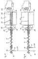
- FIG. 1 shows a preferred embodiment of a Device according to the invention for removing an analytical Consumables from a not shown in Fig. 1 Storage container that the invention Idea of a position-dependent feed force using a mechanical cam control realized and advantageous for use in very small, battery operated Analyzers is suitable.
- the device comprises an electric drive motor 1 whose driving force transmitted to a drive wheel 3 via a transmission 2 becomes.
- the drive wheel 3 is the driver pin 4th a cylindrical, helically wound transport spiral 5 non-rotatably connected.
- the transport spiral 5 is rotatable at its other end in a pivot bearing 6 stored and can rotate by their drive Longitudinal axis are offset.
- the transport spiral 5 serves as a control element mechanical path or curve control and points Sections of different slopes.
- she consists for example made of spring steel, since they are made of this material can be produced advantageously.
- a certain elastic Compliancy can in some applications may be appropriate, but is not mandatory. In most applications it will be useful the transport helix 5 from a relatively hard, little elastic spring steel as rigid as possible, i.e. with a high spring constants (spring rate).
- the transport spiral 5 is axially by a plunger 7 permeated.
- the plunger 7 is in the starting position shown in which he is completely in the transport spiral 5 is withdrawn.
- the plunger 7 from the transport helix 5 in the pushed out the arrow 8 marked direction.
- the plunger 7 a driver part 9, which is rotatable and fixed with the plunger 7 connected receptacle 10 and a driver pin arranged on the receiving socket 10 11 includes.
- the outer dimensions of the receptacle 10 are so small that they are in the axial direction through the transport spiral 5 can be moved.
- the driver pin 11 is preferred essentially transverse to the longitudinal direction of the Transport helix 5, i.e. transverse to the feed direction of the Tappet 7 arranged.
- the driver pin 11 is in one Carrier guide 12, which is parallel to the Ram 7 extends.
- Driving pin 11 When the transport helix 5 is rotating by the drive their windings exert a force on the Driving pin 11 out.
- This force consists of one Component that the driving pin 11 around the plunger 7th rotates, and a component that the driving pin 11 in Direction of the plunger 7 moves together.
- the rotary motion the driver pin 11 is through the driver guide 12 prevented or in special embodiments performed so that the remaining force component the Ram 7 promotes through the transport spiral 5.
- the axial dimensions the receptacle 10 are so large that they are always safe between the turns and does not jam can.
- the length of the measured in the axial direction Receiving socket 10 should therefore at least expediently as large as half the maximum distance between two turns the transport helix 5. In this case it is sufficient it when the plunger 7 in the forward direction in a socket 13 is guided; then the guide at the back end through the transport spiral 5 and the axially displaceable therein Receiving socket 10 causes.
- the Tappet 7 at another point for example is stored at its rear end. This can be done, for example the plunger 7 have an axial cavity, in which engages a guide mandrel from its rear end.
- another guide element may also be provided.
- the transport spiral 5 inside or serve outside supporting, longitudinally slotted sleeve.
- the If necessary, the sleeve can also function as a carrier guide 12 meet.
- the driver guide 12 can refer to the rotational position of the plunger 7 its longitudinal axis easily and precisely defined or to be controlled. This is special, for example important when the front end of the plunger 7 is in shape a blade 14 is formed, which may be advantageous can to the film of a storage container without or to penetrate only with little formation of snippets. It can then be important that the plunger 7 in one certain orientation to that from the storage container analytical consumables to be removed is to to ensure safe transport. For example should be in the case of strip-shaped test elements Blade 14 approximately perpendicular to the plane of the test strips stand to ensure safe funding.
- the defined orientation of the plunger 7 or the blade 14 on the analytical consumable to be removed is effected by the driver guide 12. It is even possible, this relative positioning as a function of To vary the transport route. If the driver guide 12 is straight, the plunger 7 rotates during of its feed not. If, on the other hand, the driver guide 12 is wound in the axial direction, rotates the plunger 7 into the respective through the driver guide 12th given location.
- the direction of movement of the plunger 7 also reverses around.
- a short phase occur in which the transport spiral 5 rotates without that the plunger 7 is moved. This phase ends as soon as another turn of the transport spiral 5 on the driver pin 11 is present and causes its displacement.
- the the resulting short dead time is not in practice annoying and can possibly by appropriate training the coupling between driver pin 11 and transport spiral 5 can be reduced or prevented.
- the Driving pin 11 at the front or rear end of the Operate the transport coil 5 arranged limit switch to to end the transport process at the end of the transport route.
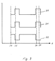
- the transport spiral 5 has different lengths Inclines on. This makes it possible for the Ram 7 exerted feed force and the feed speed of the plunger 7 depending on its axial displacement position to vary, even if the Transport helix 5 with a substantially constant Speed rotates. In the sections with a slight slope, in which the turns of the transport spiral 5 are close together, the feed force high and the feed rate slow. In the Sections in which the transport spiral 5 has a high Inclines and their turns a large distance the feed force is low and the feed speed high.
- the drive motor 1 during the feed movement of the plunger 7 loaded much more evenly than if the transport helix 5 has an even slope would have.
- the battery the device is loaded more evenly, which means more Energy can be extracted as harmful current peaks are avoided become.
- the drive motor 1 can an optimal working point can be designed so that energy efficiency improves. Total results This measure also means that the movement of the Ram 7 required for the removal of a consumable Total time is reduced.
- the varying slope of the transport spiral 5 has an effect the result is like a travel-dependent gearbox that acting on the plunger 7 during its feed movement Load changes that depend on the device the feed path are predetermined, are compensated in such a way that the drive motor 1 is substantially uniform is charged.
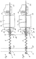
- Fig. 2 shows a cross section through an inventive Contraption.
- the transport spiral is shown 5, the receptacle 10 and the driving pin 11 in a straight-line driver guide 12.
- the Driver guide 12 is in the example shown in Formed a groove in a block.
- Other embodiments with which the position of the driving pin 11th are determined by a person skilled in the art in a simple manner to realize.
- Fig. 2 is also the recording and positioning device 19 shown for receiving a storage container, the seventeen chambers with analytical consumables having.
- the receiving device comprises 19 seventeen through holes 15 in one Perforated disk 41 positioned in front of the plunger 7 and through which the plunger 7 can be guided.
- a guide pin 16 which is in a central Bore of the storage container engages.
- the receiving device 19 To rotate the receiving device 19 is a not shown Drive provided, positioning by means of a positioning disk 17 and electrical Sliding contacts 18 takes place.
- the storage container can be opened have an evaluation code on the outside, which is automatic can be read.
- the guide pin 16 engages in a corresponding measuring device into the central hole of the storage container and keep it in the correct position for removal of consumables.
- Can at the edge of the central hole there is, for example, a drive sprocket on the storage container are in a correspondingly shaped Counterpart when using the storage container in a Analyzer can intervene and with its help Storage container is rotated in the device.
- Storage container is rotated in the device.
- the piercing openings 15 are circular, since the Shank of the plunger 7 preferably a circular one Has cross section. However, this does not necessarily apply also for the removal opening or insertion opening in the storage container, which is closed by a film are. To keep their area as small as possible these openings are often not circular but point a different form. For example, with test strips an elliptical or other elongated shape is advantageous, the longitudinal extension in the direction of Test strip level.
- FIG. 5 corresponds to the embodiment according to FIG. 1, in which the Transport helix 5 runs past the driving pin 11, so that when the direction of rotation of the transport spiral is reversed 5 the transport helix 5 is only rotated a little must be before the plunger 7 is moved back.
- the transport spiral 5 passed through an opening in the driver pin 11, which causes the dead path when reversing the rotary motion is reduced.
- a modified embodiment can for example also be provided that on the Transport helix 5 arranged a sliding liner is articulated to the driving pin 11 is.
- FIG. 5 to 8 illustrate different phases when operating the device according to the invention Fig. 1.
- the transport spiral 5 is shown with Ram 7, the receiving device 19 with guide funnel 20 and a drum-shaped storage container 21 from which from a chamber 42 shown only in FIG. 5 Test element 22 removed and into a measuring device 23 is proceeded.
- the Tappet 7 in a correct position relative to the storage container 21 are brought.
- the plunger 7 is in a basic position 24 in which he retracted into the transport coil 5 is.
- a storage container 21 is in the receiving device 19 used and by means of a positioning device becomes the chamber 42, which is a test element to be removed 22 contains, driven in front of the plunger 7.
- the insertion opening 28 and the opposite removal opening 29 the chamber 42 in which the test element 22 is located, are sealed with a foil.
- the transport spiral 5 is then in by means of the drive Rotational movement offset, whereby the plunger 7 forward moved and at the film penetration shown in Fig. 6 25 first pierces the film over the insertion opening 28. Immediately afterwards the film is at the removal opening 29 pierce through the test element 22.
- the plunger 7 is further in the storage container 21 pushed in, the test element 22 first conveyed out of the storage container 21 and then in a defined position in the measuring device 23 is positioned.
- the rotational movement of the transport spiral 5 be interrupted to carry out the measurement.
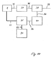
- FIG. 10 illustrates how the pushing force of a plunger depending on its Position can be realized purely electronically can.
- the control 36 takes place by means of a tachometer 37, a controller 38 with target size specification 39 and a pulse width modulated or linear controlled Output 40.
- this scheme is not as efficient like a load-dependent, mechanical transmission, because the Drive motor 1 is not always in an optimal operating point can be held.
Abstract
Description
- Fig. 1
- einen Längsschnitt durch eine erfindungsgemäße Vorrichtung,
- Fig. 2
- einen Querschnitt durch die Vorrichtung der Fig. 1,
- Fig. 3
- einen Einzelheit zu Fig. 1,
- Fig. 4
- eine Abwandlung zu Fig. 3,
- Fig. 5
- die Vorrichtung der Fig. 1 in einer Grundstellung,
- Fig. 6
- die Vorrichtung der Fig. 1 beim Durchstoßen einer Folie,
- Fig. 7
- die Vorrichtung der Fig. 1 beim Verfahren eines Testelements in eine Meßposition,
- Fig. 8
- die Vorrichtung der Fig. 1 beim Auswerfen des Testelements,
- Fig. 9
- eine Wegdiagramm zu den Figuren 5 bis 8 und
- Fig. 10
- ein Blockschaltbild einer erfindungsgemäßen Vorrichtung mit elektronischer Regelung.
- 1
- Antriebsmotor
- 2
- Getriebe
- 3
- Antriebsrad
- 4
- Mitnehmerzapfen
- 5
- Transportwendel
- 6
- Drehlager
- 7
- Stößel
- 8
- Pfeil
- 9
- Mitnehmerteil
- 10
- Aufnahmebuchse
- 11
- Mitnehmerstift
- 12
- Mitnehmerführung
- 13
- Buchse
- 14
- Klinge
- 15
- Durchstoßöffnung
- 16
- Führungsstift
- 17
- Positionierscheibe
- 18
- Schleifkontakt
- 19
- Aufnahmevorrichtung
- 20
- Führungstrichter
- 21
- Vorratsbehälter
- 22
- Testelement
- 23
- Meßvorrichtung
- 24
- Grundstellung
- 25
- Foliendurchstoß
- 26
- Gebrauchslage
- 27
- Auswurf
- 28
- Einschuböffnung
- 29
- Entnahmeöffnung
- 30
- Vorschubkraft
- 31
- Vorschubmoment
- 32
- Vorschubgeschwindigkeit
- 33
- Energiefluß
- 34
- Batterie
- 35
- Verstärker
- 36
- Steuerung
- 37
- Drehzahlmesser
- 38
- Regler
- 39
- Sollgröße
- 40
- Ausgang
- 41
- Lochscheibe
- 42
- Kammer
- s
- Position
Claims (18)
- Vorrichtung zum Entnehmen eines analytischen Verbrauchsmittels, insbesondere eines Testelements (22), aus einem Vorratsbehältnis (21), das ein oder mehrere Kammern (42) aufweist, die Verbrauchsmittel enthalten, wobei die Kammern (42) jeweils eine Entnahmeöffnung (29) zum Entnehmen eines Verbrauchsmittels und eine der Entnahmeöffnung (29) gegenüberliegende Einschuböffnung (28) zum Einführen eines Stößels (7) für den Transport des Verbrauchsmittels aufweisen und die Entnahmeöffung (29) und die Einschuböffnung (28) zur Lagerung des Verbrauchsmittels mit einer Folie verschlossen sind, umfassend einen Stößel (7), der zur Entnahme eines Verbrauchsmittels mittels einer Antriebseinheit verfahrbar ist,
dadurch gekennzeichnet, daß
die Größe der Vorschubkraft (30), die von dem Stößel (7) bei seiner der Entnahme eines Verbrauchsmittels dienenden Vorschubbewegung ausgeübt wird, in Abhängigkeit von der Position (s) des Stößels (7) steuerbar ist. - Vorrichtung nach Anspruch 1, dadurch gekennzeichnet, daß die Vorschubkraft (30) in Abhängigkeit von dem Vorschubweg steuerbar ist, den der Stößel (7) zurückgelegt hat, und der Vorschubweg relativ zu einem Teil mit einer bezüglich der Vorrichtung festen Position bestimmbar ist.
- Vorrichtung nach Anspruch 1 oder 2, dadurch gekennzeichnet, daß die Vorschubkraft (30) bei mindestens einem der folgenden Betriebszustände erhöht ist: Beim Durchstoßen (25) der Folie über der Einschuböffnung (28) durch den Stößel (7), beim Durchstoßen (25) der Folie über der Entnahmeöffnung (29) durch das Verbrauchsmittel, beim Positionieren des entnommenen Verbrauchsmittels in eine vorgegebene Gebrauchslage (26) oder beim Ausstoßen (27) eines verbrauchten Verbrauchsmittels aus einer vorgegebenen Gebrauchslage (26).
- Vorrichtung nach einem der vorhergehenden Ansprüche, dadurch gekennzeichnet, daß die Vorschubgeschwindigkeit (32) des Stößels (7) in Bereichen mit erhöhter Vorschubkraft (30) reduziert und in Bereichen mit reduzierter Vorschubkraft (30) erhöht ist.
- Vorrichtung nach einem der vorhergehenden Ansprüche, dadurch gekennzeichnet, daß die Vorschubbewegung des Stößels (7) mittels einer elektronischen Regelung der Antriebseinheit steuerbar ist.
- Vorrichtung nach einem der vorhergehenden Ansprüche, dadurch gekennzeichnet, daß die Antriebseinheit einen Antriebsmotor (1) umfaßt, der mit einer im wesentlichen konstanten Antriebsleistung und/oder einer im wesentlichen konstanten Drehzahl betreibbar ist.
- Vorrichtung nach einem der vorhergehenden Ansprüche, dadurch gekennzeichnet, daß die Vorschubbewegung des Stößels (7) mittels einer mechanischen Wegsteuerung oder einer mechanischen Kurvensteuerung steuerbar ist.
- Vorrichtung nach Anspruch 7, dadurch gekennzeichnet, daß die Weg- bzw. Kurvensteuerung ein schraubenförmig gewundenes, mittels der Antriebseinheit um seine Längsachse in Drehbewegung versetzbares und den Vorschub steuerndes Steuerelement umfaßt, das in Verbindung mit einem Mitnehmerteil steht, das den Stößel (7) beim Drehen des Steuerelements in Vorschubrichtung bewegt.
- Vorrichtung nach Anspruch 8, dadurch gekennzeichnet, daß sich die Längsachse des Steuerelements in Richtung der Vorschubbewegung des Stößels (7) erstreckt.
- Vorrichtung nach Anspruch 9, dadurch gekennzeichnet, daß der Stößel (7) das Steuerelement axial durchdringt.
- Vorrichtung nach einem der Ansprüche 8 bis 10, da-durch gekennzeichnet, daß die Steigung des Steuerelements längs seiner schraubenförmigen Windung konstant ist.
- Vorrichtung nach einem der Ansprüche 8 bis 10, da-durch gekennzeichnet, die Steigung des Steuerelements längs seiner schraubenförmigen Windung entsprechend einer gewünschten Vorschubkraft -Positions -Abhängigkeit des Stößels (7) variabel ausgebildet ist.
- Vorrichtung nach Anspruch 12, dadurch gekennzeichnet, daß die Drehzahl des Antriebsmotors (1) der Antriebseinheit und/oder die Drehzahl des Steuerelements beim Vorschub des Stößels (7) im wesentlichen konstant ist.
- Vorrichtung nach einem der Ansprüche 8 bis 13, dadurch gekennzeichnet, daß das Steuerelement eine zylinderförmige Steuerwalze mit einer auf der Mantelfläche verlaufenden Nut und das Mitnehmerteil einen in die Nut eingreifenden Nutenstein umfaßt.
- Vorrichtung nach einem der Ansprüche 8 bis 14, dadurch gekennzeichnet, daß das Steuerelement eine zylindrische, schraubenförmig gewundene Transportwendel (5) umfaßt und das Mitnehmerteil als in die Windungen der Transportwendel (5) eingreifender Mitnehmerstift (11) ausgebildet ist.
- Analysegerät zur Analyse einer medizinischen Probe mittels eines medizinischen Verbrauchsmittels, insbesondere zur Durchführung einer Analyse mittels eines Testelements (22), dadurch gekennzeichnet, daß es eine Entnahmevorrichtung nach einem der Ansprüche 1 bis 15 aufweist.
- Analysegerät nach Anspruch 16, dadurch gekennzeichnet, daß es netzunabhängig betreibbar ist.
- Verfahren zum Entnehmen eines analytischen Verbrauchsmittels, insbesondere eines Testelements (22), aus einem Vorratsbehältnis (21), das ein oder mehrere Kammern (42) aufweist, die Verbrauchsmittel enthalten, wobei die Kammern (42) jeweils eine Entnahmeöffnung (29) zum Entnehmen eines Verbrauchsmittels und eine der Entnahmeöffnung (29) gegenüberliegende Einschuböffnung (28) zum Einführen eines Stößels (7) für den Transport des Verbrauchsmittels aufweisen und die Entnahmeöffung (29) und die Einschuböffnung (28) zur Lagerung des Verbrauchsmittels mit einer Folie verschlossen sind, bei dem ein Stößel (7) zur Entnahme eines Verbrauchsmittels mittels einer Antriebseinheit verfahren wird,
dadurch gekennzeichnet, daß
die Größe der Vorschubkraft (30), die von dem Stößel (7) bei seiner der Entnahme eines Verbrauchsmittels dienenden Vorschubbewegung ausgeübt wird, in Abhängigkeit von der Position (s) des Stößels (7) gesteuert wird.
Applications Claiming Priority (2)
| Application Number | Priority Date | Filing Date | Title |
|---|---|---|---|
| DE19902601 | 1999-01-23 | ||
| DE19902601A DE19902601A1 (de) | 1999-01-23 | 1999-01-23 | Verfahren und Vorrichtung zum Entnehmen analytischer Verbrauchsmittel aus einem Vorratsbehältnis |
Publications (3)
| Publication Number | Publication Date |
|---|---|
| EP1022565A2 true EP1022565A2 (de) | 2000-07-26 |
| EP1022565A3 EP1022565A3 (de) | 2003-06-18 |
| EP1022565B1 EP1022565B1 (de) | 2007-05-30 |
Family
ID=7895164
Family Applications (1)
| Application Number | Title | Priority Date | Filing Date |
|---|---|---|---|
| EP00100255A Expired - Lifetime EP1022565B1 (de) | 1999-01-23 | 2000-01-18 | Verfahren und Vorrichtung zum Entnehmen analytischer Verbrauchsmittel aus einem Vorratsbehältnis |
Country Status (6)
| Country | Link |
|---|---|
| US (3) | US6475436B1 (de) |
| EP (1) | EP1022565B1 (de) |
| JP (1) | JP4331847B2 (de) |
| AT (1) | ATE363659T1 (de) |
| DE (2) | DE19902601A1 (de) |
| ES (1) | ES2285974T3 (de) |
Cited By (15)
| Publication number | Priority date | Publication date | Assignee | Title |
|---|---|---|---|---|
| US6497845B1 (en) * | 1998-04-24 | 2002-12-24 | Roche Diagnostics Gmbh | Storage container for analytical devices |
| DE10361261A1 (de) * | 2003-12-24 | 2005-07-28 | Roche Diagnostics Gmbh | Analysehandgerät |
| WO2005085840A1 (de) * | 2004-03-04 | 2005-09-15 | Roche Diagnostics Gmbh | Analysehandgerät mit förderweg für analytische verbrauchsmittel |
| US7501097B2 (en) | 2003-08-21 | 2009-03-10 | Roche Diagnostics Operations, Inc. | Positioning device for a test element |
| US7670562B2 (en) | 2003-11-15 | 2010-03-02 | Roche Diagnostics Operations, Inc. | Dispensing container and storage container for analytical disposables |
| US7736904B2 (en) | 2000-09-01 | 2010-06-15 | Roche Diagnostics Operations, Inc. | Method for verifying fitness of an analysis element |
| US7803318B2 (en) | 2003-12-23 | 2010-09-28 | Roche Diagnostics Operations, Inc. | Hand-held analytical device |
| EP2287605A1 (de) | 2009-08-20 | 2011-02-23 | Roche Diagnostics GmbH | Vereinfachte Magazinierung integrierter Systeme |
| WO2011045348A1 (de) | 2009-10-15 | 2011-04-21 | F. Hoffmann-La Roche Ag | Schutz vor hydrophobierenden agenzien |
| US8388905B2 (en) | 2006-03-13 | 2013-03-05 | Nipro Diagnostics, Inc. | Method and apparatus for coding diagnostic meters |
| US8388906B2 (en) | 2006-03-13 | 2013-03-05 | Nipro Diagnostics, Inc. | Apparatus for dispensing test strips |
| US8691161B2 (en) | 2004-12-13 | 2014-04-08 | Bayer Healthcare Llc | Self-contained test sensor |
| EP2770064A1 (de) | 2013-02-22 | 2014-08-27 | F. Hoffmann-La Roche AG | Hocheffiziente Herstellung von Blutglucose-Teststreifen |
| US8940246B2 (en) | 2006-03-13 | 2015-01-27 | Nipro Diagnostics, Inc. | Method and apparatus for coding diagnostic meters |
| US11559810B2 (en) | 2006-03-13 | 2023-01-24 | Trividia Health, Inc. | Method and apparatus for coding diagnostic meters |
Families Citing this family (89)
| Publication number | Priority date | Publication date | Assignee | Title |
|---|---|---|---|---|
| US6036924A (en) | 1997-12-04 | 2000-03-14 | Hewlett-Packard Company | Cassette of lancet cartridges for sampling blood |
| US6391005B1 (en) | 1998-03-30 | 2002-05-21 | Agilent Technologies, Inc. | Apparatus and method for penetration with shaft having a sensor for sensing penetration depth |
| DE19902601A1 (de) * | 1999-01-23 | 2000-07-27 | Roche Diagnostics Gmbh | Verfahren und Vorrichtung zum Entnehmen analytischer Verbrauchsmittel aus einem Vorratsbehältnis |
| US8641644B2 (en) | 2000-11-21 | 2014-02-04 | Sanofi-Aventis Deutschland Gmbh | Blood testing apparatus having a rotatable cartridge with multiple lancing elements and testing means |
| ATE485766T1 (de) | 2001-06-12 | 2010-11-15 | Pelikan Technologies Inc | Elektrisches betätigungselement für eine lanzette |
| DE60234598D1 (de) | 2001-06-12 | 2010-01-14 | Pelikan Technologies Inc | Selbstoptimierende lanzettenvorrichtung mit adaptationsmittel für zeitliche schwankungen von hauteigenschaften |
| US9795747B2 (en) | 2010-06-02 | 2017-10-24 | Sanofi-Aventis Deutschland Gmbh | Methods and apparatus for lancet actuation |
| US9226699B2 (en) | 2002-04-19 | 2016-01-05 | Sanofi-Aventis Deutschland Gmbh | Body fluid sampling module with a continuous compression tissue interface surface |
| EP1404234B1 (de) | 2001-06-12 | 2011-02-09 | Pelikan Technologies Inc. | Gerät zur erhöhung der erfolgsrate im hinblick auf die durch einen fingerstich erhaltene blutausbeute |
| US7981056B2 (en) | 2002-04-19 | 2011-07-19 | Pelikan Technologies, Inc. | Methods and apparatus for lancet actuation |
| US7749174B2 (en) | 2001-06-12 | 2010-07-06 | Pelikan Technologies, Inc. | Method and apparatus for lancet launching device intergrated onto a blood-sampling cartridge |
| US7682318B2 (en) | 2001-06-12 | 2010-03-23 | Pelikan Technologies, Inc. | Blood sampling apparatus and method |
| US7025774B2 (en) | 2001-06-12 | 2006-04-11 | Pelikan Technologies, Inc. | Tissue penetration device |
| US9427532B2 (en) | 2001-06-12 | 2016-08-30 | Sanofi-Aventis Deutschland Gmbh | Tissue penetration device |
| US8337419B2 (en) | 2002-04-19 | 2012-12-25 | Sanofi-Aventis Deutschland Gmbh | Tissue penetration device |
| US8784335B2 (en) | 2002-04-19 | 2014-07-22 | Sanofi-Aventis Deutschland Gmbh | Body fluid sampling device with a capacitive sensor |
| US7291117B2 (en) | 2002-04-19 | 2007-11-06 | Pelikan Technologies, Inc. | Method and apparatus for penetrating tissue |
| US8360992B2 (en) | 2002-04-19 | 2013-01-29 | Sanofi-Aventis Deutschland Gmbh | Method and apparatus for penetrating tissue |
| US9248267B2 (en) | 2002-04-19 | 2016-02-02 | Sanofi-Aventis Deustchland Gmbh | Tissue penetration device |
| US8267870B2 (en) | 2002-04-19 | 2012-09-18 | Sanofi-Aventis Deutschland Gmbh | Method and apparatus for body fluid sampling with hybrid actuation |
| CN100430720C (zh) * | 2002-04-19 | 2008-11-05 | 松下电器产业株式会社 | 生物传感器盒及生物传感器分给装置 |
| US7909778B2 (en) | 2002-04-19 | 2011-03-22 | Pelikan Technologies, Inc. | Method and apparatus for penetrating tissue |
| US9795334B2 (en) | 2002-04-19 | 2017-10-24 | Sanofi-Aventis Deutschland Gmbh | Method and apparatus for penetrating tissue |
| US7648468B2 (en) | 2002-04-19 | 2010-01-19 | Pelikon Technologies, Inc. | Method and apparatus for penetrating tissue |
| US9314194B2 (en) | 2002-04-19 | 2016-04-19 | Sanofi-Aventis Deutschland Gmbh | Tissue penetration device |
| US7331931B2 (en) | 2002-04-19 | 2008-02-19 | Pelikan Technologies, Inc. | Method and apparatus for penetrating tissue |
| US7175642B2 (en) | 2002-04-19 | 2007-02-13 | Pelikan Technologies, Inc. | Methods and apparatus for lancet actuation |
| US7297122B2 (en) | 2002-04-19 | 2007-11-20 | Pelikan Technologies, Inc. | Method and apparatus for penetrating tissue |
| US7674232B2 (en) | 2002-04-19 | 2010-03-09 | Pelikan Technologies, Inc. | Method and apparatus for penetrating tissue |
| US7229458B2 (en) | 2002-04-19 | 2007-06-12 | Pelikan Technologies, Inc. | Method and apparatus for penetrating tissue |
| US7226461B2 (en) | 2002-04-19 | 2007-06-05 | Pelikan Technologies, Inc. | Method and apparatus for a multi-use body fluid sampling device with sterility barrier release |
| US7491178B2 (en) | 2002-04-19 | 2009-02-17 | Pelikan Technologies, Inc. | Method and apparatus for penetrating tissue |
| US8579831B2 (en) | 2002-04-19 | 2013-11-12 | Sanofi-Aventis Deutschland Gmbh | Method and apparatus for penetrating tissue |
| US7892183B2 (en) | 2002-04-19 | 2011-02-22 | Pelikan Technologies, Inc. | Method and apparatus for body fluid sampling and analyte sensing |
| US7547287B2 (en) | 2002-04-19 | 2009-06-16 | Pelikan Technologies, Inc. | Method and apparatus for penetrating tissue |
| US8702624B2 (en) | 2006-09-29 | 2014-04-22 | Sanofi-Aventis Deutschland Gmbh | Analyte measurement device with a single shot actuator |
| US7232451B2 (en) | 2002-04-19 | 2007-06-19 | Pelikan Technologies, Inc. | Method and apparatus for penetrating tissue |
| US7717863B2 (en) | 2002-04-19 | 2010-05-18 | Pelikan Technologies, Inc. | Method and apparatus for penetrating tissue |
| US7901362B2 (en) | 2002-04-19 | 2011-03-08 | Pelikan Technologies, Inc. | Method and apparatus for penetrating tissue |
| US7976476B2 (en) | 2002-04-19 | 2011-07-12 | Pelikan Technologies, Inc. | Device and method for variable speed lancet |
| US7892185B2 (en) | 2002-04-19 | 2011-02-22 | Pelikan Technologies, Inc. | Method and apparatus for body fluid sampling and analyte sensing |
| US7371247B2 (en) | 2002-04-19 | 2008-05-13 | Pelikan Technologies, Inc | Method and apparatus for penetrating tissue |
| US8221334B2 (en) | 2002-04-19 | 2012-07-17 | Sanofi-Aventis Deutschland Gmbh | Method and apparatus for penetrating tissue |
| JP2006511820A (ja) * | 2002-12-23 | 2006-04-06 | エフ ホフマン−ラ ロッシュ アクチェン ゲゼルシャフト | 分析システム内の試験エレメントを搬送するための移送装置 |
| US8574895B2 (en) | 2002-12-30 | 2013-11-05 | Sanofi-Aventis Deutschland Gmbh | Method and apparatus using optical techniques to measure analyte levels |
| EP1628567B1 (de) | 2003-05-30 | 2010-08-04 | Pelikan Technologies Inc. | Verfahren und vorrichtung zur injektion von flüssigkeit |
| DK1633235T3 (da) | 2003-06-06 | 2014-08-18 | Sanofi Aventis Deutschland | Apparat til udtagelse af legemsvæskeprøver og detektering af analyt |
| WO2006001797A1 (en) | 2004-06-14 | 2006-01-05 | Pelikan Technologies, Inc. | Low pain penetrating |
| US8282576B2 (en) | 2003-09-29 | 2012-10-09 | Sanofi-Aventis Deutschland Gmbh | Method and apparatus for an improved sample capture device |
| EP1680014A4 (de) | 2003-10-14 | 2009-01-21 | Pelikan Technologies Inc | Verfahren und gerät für eine variable anwenderschnittstelle |
| DE10348283A1 (de) * | 2003-10-17 | 2005-05-12 | Roche Diagnostics Gmbh | Handgerät zur Untersuchung einer Körperflüssigkeit |
| US7347342B2 (en) * | 2003-10-30 | 2008-03-25 | Elmar Grandy | Container for holding sterile goods and sterile goods dispenser |
| EP1706026B1 (de) | 2003-12-31 | 2017-03-01 | Sanofi-Aventis Deutschland GmbH | Verfahren und vorrichtung zur verbesserung der fluidströmung und der probennahme |
| US7822454B1 (en) | 2005-01-03 | 2010-10-26 | Pelikan Technologies, Inc. | Fluid sampling device with improved analyte detecting member configuration |
| US8828203B2 (en) | 2004-05-20 | 2014-09-09 | Sanofi-Aventis Deutschland Gmbh | Printable hydrogels for biosensors |
| US9775553B2 (en) | 2004-06-03 | 2017-10-03 | Sanofi-Aventis Deutschland Gmbh | Method and apparatus for a fluid sampling device |
| EP1765194A4 (de) | 2004-06-03 | 2010-09-29 | Pelikan Technologies Inc | Verfahren und gerät für eine flüssigkeitsentnahmenvorrichtung |
| DE102004033317A1 (de) * | 2004-07-09 | 2006-02-09 | Roche Diagnostics Gmbh | Analytisches Testelement |
| DE102004036474A1 (de) | 2004-07-28 | 2006-03-23 | Roche Diagnostics Gmbh | Analysesystem zur Analyse einer Probe auf einem Testelement |
| JP2006170974A (ja) | 2004-12-15 | 2006-06-29 | F Hoffmann-La Roche Ag | 分析試験エレメント上での液体試料の分析用分析システム |
| DE102004060322A1 (de) | 2004-12-15 | 2006-06-22 | Roche Diagnostics Gmbh | Analysesystem mit einem elektrischen Anschlusssystem für ein Testelement |
| US8652831B2 (en) | 2004-12-30 | 2014-02-18 | Sanofi-Aventis Deutschland Gmbh | Method and apparatus for analyte measurement test time |
| WO2006107914A2 (en) * | 2005-04-04 | 2006-10-12 | Facet Technologies, Llc | Narrow-profile lancing device |
| EP1712910A1 (de) * | 2005-04-12 | 2006-10-18 | F.Hoffmann-La Roche Ag | Analysegerät zur Analyse einer Probenflüssigkeit mittels eines Testelements |
| EP1780541B1 (de) | 2005-10-25 | 2008-10-15 | F.Hoffmann-La Roche Ag | Analysegerät zur Analyse einer Probe auf einem Testelement |
| US7887757B2 (en) * | 2006-05-09 | 2011-02-15 | Becton, Dickinson And Company | Method and apparatus for dispensing diagnostic test strips |
| US7597853B2 (en) | 2006-05-09 | 2009-10-06 | Becton, Dickinson And Company | Method and apparatus for dispensing diagnostic test strips |
| US20090312622A1 (en) | 2006-09-28 | 2009-12-17 | Werner Regittnig | Device And Method For Determining A Value Of A Physiological Parameter Of A Body Fluid |
| EP1970711A1 (de) * | 2007-03-16 | 2008-09-17 | Radiometer Medical ApS | Reagenzschale |
| WO2009032760A2 (en) * | 2007-08-30 | 2009-03-12 | Pepex Biomedical Llc | Electrochmical sensor and method for manufacturing |
| US9044178B2 (en) * | 2007-08-30 | 2015-06-02 | Pepex Biomedical, Llc | Electrochemical sensor and method for manufacturing |
| WO2009126900A1 (en) | 2008-04-11 | 2009-10-15 | Pelikan Technologies, Inc. | Method and apparatus for analyte detecting device |
| US8394637B2 (en) | 2008-06-02 | 2013-03-12 | Roche Diagnostics Operations, Inc. | Handheld analyzer for testing a sample |
| WO2010056878A2 (en) | 2008-11-14 | 2010-05-20 | Pepex Biomedical, Llc | Electrochemical sensor module |
| US8506740B2 (en) | 2008-11-14 | 2013-08-13 | Pepex Biomedical, Llc | Manufacturing electrochemical sensor module |
| US8951377B2 (en) | 2008-11-14 | 2015-02-10 | Pepex Biomedical, Inc. | Manufacturing electrochemical sensor module |
| US8147755B2 (en) * | 2008-11-26 | 2012-04-03 | Roche Diagnostics Operations, Inc. | Drum type container for analytical elements |
| US9375169B2 (en) | 2009-01-30 | 2016-06-28 | Sanofi-Aventis Deutschland Gmbh | Cam drive for managing disposable penetrating member actions with a single motor and motor and control system |
| JP2011053110A (ja) * | 2009-09-02 | 2011-03-17 | Hitachi High-Technologies Corp | 化学分析装置 |
| US8965476B2 (en) | 2010-04-16 | 2015-02-24 | Sanofi-Aventis Deutschland Gmbh | Tissue penetration device |
| EP2463030A1 (de) * | 2010-12-08 | 2012-06-13 | F. Hoffmann-La Roche AG | Lageranordnung zur Bereitstellung von Reagenzienträgern zur Verarbeitung in einem Analysesystem |
| KR20140036178A (ko) * | 2011-05-13 | 2014-03-25 | 베크만 컬터, 인코포레이티드 | 실험실 제품 이송 요소 및 경로 배열 구조체 |
| WO2012162151A2 (en) | 2011-05-20 | 2012-11-29 | Pepex Biomedical, Inc. | Manufacturing electrochemical sensor modules |
| SG2014014559A (en) | 2011-10-17 | 2014-08-28 | Hoffmann La Roche | Troponin and bnp based diagnosis of risk patients and cause of stroke |
| WO2014089058A1 (en) | 2012-12-03 | 2014-06-12 | Pepex Biomedical, Inc. | Sensor module and method of using a sensor module |
| US11045124B2 (en) | 2014-06-04 | 2021-06-29 | Pepex Biomedical, Inc. | Electrochemical sensors and methods for making electrochemical sensors using advanced printing technology |
| CN107820446B (zh) | 2015-05-01 | 2020-05-01 | 雅培制药有限公司 | 用于去除容器的液体内含物的设备 |
| US9798886B2 (en) | 2015-07-08 | 2017-10-24 | International Business Machines Corporation | Bio-medical sensing platform |
| JP6954907B2 (ja) * | 2015-12-07 | 2021-10-27 | 6 リバー システムズ, エルエルシー | モータ駆動カートを用いた倉庫自動化システムおよび方法 |
Citations (3)
| Publication number | Priority date | Publication date | Assignee | Title |
|---|---|---|---|---|
| EP0357935A1 (de) * | 1988-09-06 | 1990-03-14 | BAUER, Dieter, Dipl.-Ing. | Spindeltrieb für einen Teleskoptisch |
| US5332549A (en) * | 1992-07-01 | 1994-07-26 | Pb Diagnostic Systems, Inc. | Assay module transport apparatus for use in an automated analytical instrument |
| US5510266A (en) * | 1995-05-05 | 1996-04-23 | Bayer Corporation | Method and apparatus of handling multiple sensors in a glucose monitoring instrument system |
Family Cites Families (37)
| Publication number | Priority date | Publication date | Assignee | Title |
|---|---|---|---|---|
| FR2135984A5 (de) * | 1971-03-01 | 1972-12-22 | Envirotech Corp | |
| JPS5770426A (en) * | 1980-10-21 | 1982-04-30 | Seishin Seiyaku Kk | Automatic sampler |
| DE3314961A1 (de) * | 1983-04-25 | 1984-10-25 | Boehringer Mannheim Gmbh, 6800 Mannheim | Analysegeraet zur photometrischen bestimmung eines parameters einer fluessigkeit |
| SE8305704D0 (sv) | 1983-10-18 | 1983-10-18 | Leo Ab | Cuvette |
| US4569828A (en) * | 1984-11-27 | 1986-02-11 | Gakei Electric Works Co., Ltd. | Crystal pulling apparatus for making single crystals of compound semiconductors containing a volatile component |
| JPS62273456A (ja) * | 1986-05-21 | 1987-11-27 | Tosoh Corp | 分析装置用に用いるテストカツプのシ−ル箔破開用シ−ルブレ−カ |
| JPS6332324A (ja) * | 1986-07-26 | 1988-02-12 | Hitachi Ltd | 液体分注方法 |
| US4872591A (en) * | 1987-11-19 | 1989-10-10 | Konopka Richard O | Medication dispenser |
| US4951512A (en) * | 1988-06-23 | 1990-08-28 | Baxter International Inc. | System for providing access to sealed containers |
| JPH0277652A (ja) * | 1988-09-14 | 1990-03-16 | Hitachi Ltd | 分注装置 |
| DE3855010T2 (de) * | 1988-12-29 | 1996-06-13 | Bayer Ag | Integrierter probennehmer für geschlossene und offene probencontainer |
| EP0433436B1 (de) * | 1989-07-07 | 1998-06-10 | Dade Behring Inc. | Vorrichtung zur entfernung von rückständen aus verschlossenen probegefässen |
| JP2886894B2 (ja) * | 1989-07-24 | 1999-04-26 | 株式会社日立製作所 | 自動分析装置 |
| CA2040693A1 (en) * | 1990-04-18 | 1991-10-19 | James H. Lipscomb | Method and apparatus for pipetting liquid from a sealed container |
| BR9206198A (pt) * | 1991-06-26 | 1994-11-29 | Ppg Industries Inc | Aparelho sensor hidratado de circuito integrado |
| DE4212315A1 (de) | 1992-04-13 | 1993-10-14 | Boehringer Mannheim Gmbh | Blutlanzettenvorrichtung zur Entnahme von Blut für Diagnosezwecke |
| DE4310808C2 (de) * | 1993-04-02 | 1995-06-22 | Boehringer Mannheim Gmbh | System zur Dosierung von Flüssigkeiten |
| US5271896A (en) * | 1993-04-16 | 1993-12-21 | Eastman Kodak Company | Plunger and driver mechanism for an analyzer |
| DK0622119T3 (da) * | 1993-04-23 | 2000-04-10 | Roche Diagnostics Gmbh | System til forråd af testelementer |
| DE4320463A1 (de) | 1993-06-21 | 1994-12-22 | Boehringer Mannheim Gmbh | Blutlanzettenvorrichtung zur Entnahme von Blut für Diagnosezwecke |
| DE4326931A1 (de) * | 1993-08-11 | 1995-02-16 | Hoechst Ag | Vorrichtung zum Entnehmen von festen Arzneiformen aus Blisterverpackungen |
| US5777210A (en) * | 1996-04-25 | 1998-07-07 | Voelker Sensors, Inc. | Oil quality sensor measuring bead volume |
| US5762770A (en) | 1994-02-21 | 1998-06-09 | Boehringer Mannheim Corporation | Electrochemical biosensor test strip |
| US5517867A (en) * | 1994-07-15 | 1996-05-21 | E. I. Du Pont De Nemours And Company | Liquid extraction apparatus |
| US5630986A (en) | 1995-01-13 | 1997-05-20 | Bayer Corporation | Dispensing instrument for fluid monitoring sensors |
| CA2170560C (en) | 1995-04-17 | 2005-10-25 | Joseph L. Moulton | Means of handling multiple sensors in a glucose monitoring instrument system |
| US6156565A (en) * | 1996-02-21 | 2000-12-05 | Biomerieux, Inc. | Incubation station for test sample cards |
| DK0901634T3 (da) * | 1996-05-30 | 2002-06-10 | Radiometer Medical As | System til bestemmelse af mindst en parameter i mindst en prøve af en fysiologisk væske samt en kassette |
| DE19629656A1 (de) | 1996-07-23 | 1998-01-29 | Boehringer Mannheim Gmbh | Diagnostischer Testträger mit mehrschichtigem Testfeld und Verfahren zur Bestimmung von Analyt mit dessen Hilfe |
| DE19629657A1 (de) | 1996-07-23 | 1998-01-29 | Boehringer Mannheim Gmbh | Volumenunabhängiger diagnostischer Testträger und Verfahren zur Bestimmung von Analyt mit dessen Hilfe |
| DE19753847A1 (de) | 1997-12-04 | 1999-06-10 | Roche Diagnostics Gmbh | Analytisches Testelement mit Kapillarkanal |
| JPH11183484A (ja) * | 1997-12-17 | 1999-07-09 | Olympus Optical Co Ltd | 自動分析装置 |
| SG102538A1 (en) * | 1998-04-24 | 2004-03-26 | Roche Diagnostics Gmbh | Storage container for analytical devices |
| DE19854316A1 (de) | 1998-04-24 | 1999-10-28 | Roche Diagnostics Gmbh | Vorratsbehältnis für analytische Hilfsmittel |
| JP3771380B2 (ja) * | 1998-08-31 | 2006-04-26 | シスメックス株式会社 | 液体吸引装置 |
| US6145762A (en) * | 1998-10-19 | 2000-11-14 | Cummins Engine Company, Inc. | Variable rate spring for a fuel injector |
| DE19902601A1 (de) * | 1999-01-23 | 2000-07-27 | Roche Diagnostics Gmbh | Verfahren und Vorrichtung zum Entnehmen analytischer Verbrauchsmittel aus einem Vorratsbehältnis |
-
1999
- 1999-01-23 DE DE19902601A patent/DE19902601A1/de not_active Withdrawn
-
2000
- 2000-01-18 ES ES00100255T patent/ES2285974T3/es not_active Expired - Lifetime
- 2000-01-18 DE DE50014353T patent/DE50014353D1/de not_active Expired - Lifetime
- 2000-01-18 EP EP00100255A patent/EP1022565B1/de not_active Expired - Lifetime
- 2000-01-18 AT AT00100255T patent/ATE363659T1/de active
- 2000-01-21 JP JP2000012901A patent/JP4331847B2/ja not_active Expired - Lifetime
- 2000-01-21 US US09/489,502 patent/US6475436B1/en not_active Expired - Lifetime
-
2002
- 2002-10-01 US US10/263,267 patent/US7569187B2/en not_active Expired - Fee Related
- 2002-10-01 US US10/262,907 patent/US7211437B2/en not_active Expired - Lifetime
Patent Citations (3)
| Publication number | Priority date | Publication date | Assignee | Title |
|---|---|---|---|---|
| EP0357935A1 (de) * | 1988-09-06 | 1990-03-14 | BAUER, Dieter, Dipl.-Ing. | Spindeltrieb für einen Teleskoptisch |
| US5332549A (en) * | 1992-07-01 | 1994-07-26 | Pb Diagnostic Systems, Inc. | Assay module transport apparatus for use in an automated analytical instrument |
| US5510266A (en) * | 1995-05-05 | 1996-04-23 | Bayer Corporation | Method and apparatus of handling multiple sensors in a glucose monitoring instrument system |
Non-Patent Citations (1)
| Title |
|---|
| N.M.SCHMIDT ET AL.: "understanding automation systems" 1984 , TEXAS INSTRUMENTS , USA XP002238432 * Seite 60, Absatz 2 * * |
Cited By (33)
| Publication number | Priority date | Publication date | Assignee | Title |
|---|---|---|---|---|
| US7547417B2 (en) | 1998-04-24 | 2009-06-16 | Roche Diagnostics Gmbh | Storage container for analytical devices |
| US6497845B1 (en) * | 1998-04-24 | 2002-12-24 | Roche Diagnostics Gmbh | Storage container for analytical devices |
| US7736904B2 (en) | 2000-09-01 | 2010-06-15 | Roche Diagnostics Operations, Inc. | Method for verifying fitness of an analysis element |
| US7501097B2 (en) | 2003-08-21 | 2009-03-10 | Roche Diagnostics Operations, Inc. | Positioning device for a test element |
| US7670562B2 (en) | 2003-11-15 | 2010-03-02 | Roche Diagnostics Operations, Inc. | Dispensing container and storage container for analytical disposables |
| US7803318B2 (en) | 2003-12-23 | 2010-09-28 | Roche Diagnostics Operations, Inc. | Hand-held analytical device |
| DE10361261A1 (de) * | 2003-12-24 | 2005-07-28 | Roche Diagnostics Gmbh | Analysehandgerät |
| US7964147B2 (en) | 2003-12-24 | 2011-06-21 | Roche Diagnostics Operations, Inc. | Hand-held analysis device |
| DE10361261B4 (de) * | 2003-12-24 | 2006-02-09 | Roche Diagnostics Gmbh | Analysehandgerät |
| DE102004010529A1 (de) * | 2004-03-04 | 2005-09-22 | Roche Diagnostics Gmbh | Analysehandgerät |
| EP1936374A1 (de) | 2004-03-04 | 2008-06-25 | Roche Diagnostics GmbH | Analysehandgerät mit Förderweg für analytische Verbrauchsmittel |
| JP2007526464A (ja) * | 2004-03-04 | 2007-09-13 | エフ ホフマン−ラ ロッシュ アクチェン ゲゼルシャフト | 試験エレメント用の搬送路を装備した分析携行端末 |
| DE102004010529B4 (de) * | 2004-03-04 | 2007-09-06 | Roche Diagnostics Gmbh | Analysehandgerät |
| US7922974B2 (en) | 2004-03-04 | 2011-04-12 | Roche Diagnostics Operations, Inc. | Handheld apparatus for analysis with a conveyance path for test elements |
| WO2005085840A1 (de) * | 2004-03-04 | 2005-09-15 | Roche Diagnostics Gmbh | Analysehandgerät mit förderweg für analytische verbrauchsmittel |
| US8691161B2 (en) | 2004-12-13 | 2014-04-08 | Bayer Healthcare Llc | Self-contained test sensor |
| US9383351B2 (en) | 2004-12-13 | 2016-07-05 | Ascensia Diabetes Care Holdings Ag | Self-contained test sensor |
| US8815607B2 (en) | 2004-12-13 | 2014-08-26 | Bayer Healthcare Llc | Self-contained test sensor |
| US11559810B2 (en) | 2006-03-13 | 2023-01-24 | Trividia Health, Inc. | Method and apparatus for coding diagnostic meters |
| US8388905B2 (en) | 2006-03-13 | 2013-03-05 | Nipro Diagnostics, Inc. | Method and apparatus for coding diagnostic meters |
| US8388906B2 (en) | 2006-03-13 | 2013-03-05 | Nipro Diagnostics, Inc. | Apparatus for dispensing test strips |
| US10814325B2 (en) | 2006-03-13 | 2020-10-27 | Trividia Health, Inc. | Method and apparatus for coding diagnostic meters |
| US9623412B2 (en) | 2006-03-13 | 2017-04-18 | Trividia Health, Inc. | Method and apparatus for coding diagnostic meters |
| US8940246B2 (en) | 2006-03-13 | 2015-01-27 | Nipro Diagnostics, Inc. | Method and apparatus for coding diagnostic meters |
| WO2011020914A1 (de) | 2009-08-20 | 2011-02-24 | F. Hoffmann-La Roche Ag | Vereinfachte magazinierung integrierter systeme |
| EP2287605A1 (de) | 2009-08-20 | 2011-02-23 | Roche Diagnostics GmbH | Vereinfachte Magazinierung integrierter Systeme |
| EP2843406A2 (de) | 2009-08-20 | 2015-03-04 | F. Hoffmann-La Roche AG | Diagnostisches Produkt umfassend Teststreifen mit einem Enzym und einem stabilisierenden Coenzym |
| US9528977B2 (en) | 2009-08-20 | 2016-12-27 | Roche Diabetes Care, Inc. | Simplified storage of at least one test element including a dry reagent layer having an enzyme and a stabilized coenzyme |
| WO2011045348A1 (de) | 2009-10-15 | 2011-04-21 | F. Hoffmann-La Roche Ag | Schutz vor hydrophobierenden agenzien |
| US9329164B2 (en) | 2009-10-15 | 2016-05-03 | Roche Diabetes Care, Inc. | Protection from hydrophobizing agents |
| EP2322924A1 (de) | 2009-10-15 | 2011-05-18 | F. Hoffmann-La Roche AG | Schutz vor hydrophobierenden Agenzien |
| WO2014128271A1 (de) | 2013-02-22 | 2014-08-28 | F. Hoffmann-La Roche Ag | Hocheffiziente herstellung von blutglucose-teststreifen |
| EP2770064A1 (de) | 2013-02-22 | 2014-08-27 | F. Hoffmann-La Roche AG | Hocheffiziente Herstellung von Blutglucose-Teststreifen |
Also Published As
| Publication number | Publication date |
|---|---|
| US7569187B2 (en) | 2009-08-04 |
| US20030027343A1 (en) | 2003-02-06 |
| JP4331847B2 (ja) | 2009-09-16 |
| EP1022565B1 (de) | 2007-05-30 |
| US6475436B1 (en) | 2002-11-05 |
| US7211437B2 (en) | 2007-05-01 |
| DE19902601A1 (de) | 2000-07-27 |
| ATE363659T1 (de) | 2007-06-15 |
| EP1022565A3 (de) | 2003-06-18 |
| JP2000214173A (ja) | 2000-08-04 |
| ES2285974T3 (es) | 2007-12-01 |
| US20030039584A1 (en) | 2003-02-27 |
| DE50014353D1 (de) | 2007-07-12 |
Similar Documents
| Publication | Publication Date | Title |
|---|---|---|
| EP1022565B1 (de) | Verfahren und Vorrichtung zum Entnehmen analytischer Verbrauchsmittel aus einem Vorratsbehältnis | |
| EP1825257B1 (de) | Diagnosesystem zum ermitteln von stoffkonzentrationen in flüssigen proben | |
| EP2236082B1 (de) | Gerät zur Gewinnung und Analyse einer Blutprobe | |
| EP1745284B1 (de) | Analysehandgerät mit förderweg für analytische verbrauchsmittel | |
| DE60113846T2 (de) | Vorrichtung zur messung der konzentration eines analyts in einer flüssigkeit | |
| EP2130493B1 (de) | Analysesystem zur Bestimmung eines Analyten in einer Körperflüssigkeit, Magazin für ein Analysegerät und Verfahren zur Herstellung eines Magazins für ein Analysegerät. | |
| DE60213055T2 (de) | Testvorrichtung mit Mitteln zum Aufbewahren und Dispensieren von diagnostischen Streifen | |
| EP0974061B1 (de) | Magazin zur bevorratung von testelementen | |
| EP2191773B1 (de) | Bandmagazin für ein Handgerät zur Untersuchung einer Körperflüssigkeit, sowie Handgerät | |
| EP2190352B1 (de) | Kombinationsantrieb für ein probengewinnungssystem zum gewinnen einer flüssigen probe | |
| DE10353445B4 (de) | Spenderbehältnis und Vorratsbehältnis für analytische Verbrauchsmittel | |
| DE1648865A1 (de) | Vorrichtung zur automatischen Durchfuehrung von Analysenreihen | |
| EP2079364B1 (de) | Probengewinnungssystem zum gewinnen einer flüssigen probe | |
| DE602004005157T2 (de) | Sensorabgabeeinrichtung | |
| DE10360786A1 (de) | Analysehandgerät | |
| DE2803345B1 (de) | Blutprobenentnahmegeraet | |
| DE102004033317A1 (de) | Analytisches Testelement | |
| EP1203563A2 (de) | Analytisches Hilfsmittel mit integrierter Lanzette | |
| WO2008110287A2 (de) | Analysesystem zur bestimmung eines analyten in einer körperflüssigkeit und disposibles integriertes probengewinnungs- und analyseelement | |
| EP1992283B1 (de) | Stechsystem | |
| EP2311373A1 (de) | Stechsystem zur Entnahme einer Körperflüssigkeit | |
| EP1726951A1 (de) | Magazine zur Aufnahme von Testelementen | |
| EP1792568A1 (de) | Wieder verwendbare Stechhilfe und Verfahren zum Ausführen einer Stechbewegung mittels einer wieder verwendbaren Stechhilfe | |
| DE19516981C2 (de) | Teststreifen-Zuführgerät | |
| EP2683485A1 (de) | Probenbehältnis |
Legal Events
| Date | Code | Title | Description |
|---|---|---|---|
| PUAI | Public reference made under article 153(3) epc to a published international application that has entered the european phase |
Free format text: ORIGINAL CODE: 0009012 |
|
| 17P | Request for examination filed |
Effective date: 20000118 |
|
| AK | Designated contracting states |
Kind code of ref document: A2 Designated state(s): AT BE CH CY DE DK ES FI FR GB GR IE IT LI LU MC NL PT SE |
|
| AX | Request for extension of the european patent |
Free format text: AL;LT;LV;MK;RO;SI |
|
| PUAL | Search report despatched |
Free format text: ORIGINAL CODE: 0009013 |
|
| RIC1 | Information provided on ipc code assigned before grant |
Ipc: 7G 01N 33/487 B Ipc: 7F 16H 25/12 B Ipc: 7B 23Q 5/40 B Ipc: 7G 01N 35/00 B Ipc: 7G 01N 33/48 A Ipc: 7B 01L 11/00 B |
|
| AK | Designated contracting states |
Designated state(s): AT BE CH CY DE DK ES FI FR GB GR IE IT LI LU MC NL PT SE |
|
| AX | Request for extension of the european patent |
Extension state: AL LT LV MK RO SI |
|
| AKX | Designation fees paid |
Designated state(s): AT BE CH CY DE DK ES FI FR GB GR IE IT LI LU MC NL PT SE |
|
| 17Q | First examination report despatched |
Effective date: 20050209 |
|
| GRAP | Despatch of communication of intention to grant a patent |
Free format text: ORIGINAL CODE: EPIDOSNIGR1 |
|
| GRAS | Grant fee paid |
Free format text: ORIGINAL CODE: EPIDOSNIGR3 |
|
| GRAA | (expected) grant |
Free format text: ORIGINAL CODE: 0009210 |
|
| AK | Designated contracting states |
Kind code of ref document: B1 Designated state(s): AT BE CH CY DE DK ES FI FR GB GR IE IT LI LU MC NL PT SE |
|
| PG25 | Lapsed in a contracting state [announced via postgrant information from national office to epo] |
Ref country code: FI Free format text: LAPSE BECAUSE OF FAILURE TO SUBMIT A TRANSLATION OF THE DESCRIPTION OR TO PAY THE FEE WITHIN THE PRESCRIBED TIME-LIMIT Effective date: 20070530 |
|
| REG | Reference to a national code |
Ref country code: GB Ref legal event code: FG4D Free format text: NOT ENGLISH |
|
| REG | Reference to a national code |
Ref country code: CH Ref legal event code: EP Ref country code: CH Ref legal event code: NV Representative=s name: A. BRAUN, BRAUN, HERITIER, ESCHMANN AG PATENTANWAE |
|
| GBT | Gb: translation of ep patent filed (gb section 77(6)(a)/1977) |
Effective date: 20070615 |
|
| REG | Reference to a national code |
Ref country code: IE Ref legal event code: FG4D Free format text: LANGUAGE OF EP DOCUMENT: GERMAN |
|
| REF | Corresponds to: |
Ref document number: 50014353 Country of ref document: DE Date of ref document: 20070712 Kind code of ref document: P |
|
| PG25 | Lapsed in a contracting state [announced via postgrant information from national office to epo] |
Ref country code: SE Free format text: LAPSE BECAUSE OF FAILURE TO SUBMIT A TRANSLATION OF THE DESCRIPTION OR TO PAY THE FEE WITHIN THE PRESCRIBED TIME-LIMIT Effective date: 20070830 |
|
| ET | Fr: translation filed | ||
| REG | Reference to a national code |
Ref country code: ES Ref legal event code: FG2A Ref document number: 2285974 Country of ref document: ES Kind code of ref document: T3 |
|
| NLV1 | Nl: lapsed or annulled due to failure to fulfill the requirements of art. 29p and 29m of the patents act | ||
| REG | Reference to a national code |
Ref country code: IE Ref legal event code: FD4D |
|
| PG25 | Lapsed in a contracting state [announced via postgrant information from national office to epo] |
Ref country code: PT Free format text: LAPSE BECAUSE OF FAILURE TO SUBMIT A TRANSLATION OF THE DESCRIPTION OR TO PAY THE FEE WITHIN THE PRESCRIBED TIME-LIMIT Effective date: 20071030 Ref country code: IE Free format text: LAPSE BECAUSE OF FAILURE TO SUBMIT A TRANSLATION OF THE DESCRIPTION OR TO PAY THE FEE WITHIN THE PRESCRIBED TIME-LIMIT Effective date: 20070530 Ref country code: DK Free format text: LAPSE BECAUSE OF FAILURE TO SUBMIT A TRANSLATION OF THE DESCRIPTION OR TO PAY THE FEE WITHIN THE PRESCRIBED TIME-LIMIT Effective date: 20070530 Ref country code: NL Free format text: LAPSE BECAUSE OF FAILURE TO SUBMIT A TRANSLATION OF THE DESCRIPTION OR TO PAY THE FEE WITHIN THE PRESCRIBED TIME-LIMIT Effective date: 20070530 |
|
| PLBE | No opposition filed within time limit |
Free format text: ORIGINAL CODE: 0009261 |
|
| STAA | Information on the status of an ep patent application or granted ep patent |
Free format text: STATUS: NO OPPOSITION FILED WITHIN TIME LIMIT |
|
| PG25 | Lapsed in a contracting state [announced via postgrant information from national office to epo] |
Ref country code: GR Free format text: LAPSE BECAUSE OF FAILURE TO SUBMIT A TRANSLATION OF THE DESCRIPTION OR TO PAY THE FEE WITHIN THE PRESCRIBED TIME-LIMIT Effective date: 20070831 |
|
| 26N | No opposition filed |
Effective date: 20080303 |
|
| REG | Reference to a national code |
Ref country code: CH Ref legal event code: PFA Owner name: ROCHE DIAGNOSTICS GMBH Free format text: ROCHE DIAGNOSTICS GMBH#SANDHOFER STRASSE 116#68305 MANNHEIM (DE) -TRANSFER TO- ROCHE DIAGNOSTICS GMBH#SANDHOFER STRASSE 116#68305 MANNHEIM (DE) |
|
| BERE | Be: lapsed |
Owner name: ROCHE DIAGNOSTICS G.M.B.H. Effective date: 20080131 |
|
| PG25 | Lapsed in a contracting state [announced via postgrant information from national office to epo] |
Ref country code: MC Free format text: LAPSE BECAUSE OF NON-PAYMENT OF DUE FEES Effective date: 20080131 |
|
| PG25 | Lapsed in a contracting state [announced via postgrant information from national office to epo] |
Ref country code: BE Free format text: LAPSE BECAUSE OF NON-PAYMENT OF DUE FEES Effective date: 20080131 |
|
| PG25 | Lapsed in a contracting state [announced via postgrant information from national office to epo] |
Ref country code: CY Free format text: LAPSE BECAUSE OF FAILURE TO SUBMIT A TRANSLATION OF THE DESCRIPTION OR TO PAY THE FEE WITHIN THE PRESCRIBED TIME-LIMIT Effective date: 20070530 |
|
| PG25 | Lapsed in a contracting state [announced via postgrant information from national office to epo] |
Ref country code: LU Free format text: LAPSE BECAUSE OF NON-PAYMENT OF DUE FEES Effective date: 20080118 |
|
| REG | Reference to a national code |
Ref country code: CH Ref legal event code: PCAR Free format text: NEW ADDRESS: HOLBEINSTRASSE 36-38, 4051 BASEL (CH) |
|
| REG | Reference to a national code |
Ref country code: FR Ref legal event code: PLFP Year of fee payment: 17 |
|
| REG | Reference to a national code |
Ref country code: DE Ref legal event code: R081 Ref document number: 50014353 Country of ref document: DE Owner name: ROCHE DIABETES CARE GMBH, DE Free format text: FORMER OWNER: ROCHE DIAGNOSTICS GMBH, 68305 MANNHEIM, DE |
|
| PGFP | Annual fee paid to national office [announced via postgrant information from national office to epo] |
Ref country code: ES Payment date: 20160108 Year of fee payment: 17 Ref country code: CH Payment date: 20160125 Year of fee payment: 17 |
|
| PGFP | Annual fee paid to national office [announced via postgrant information from national office to epo] |
Ref country code: AT Payment date: 20151229 Year of fee payment: 17 |
|
| REG | Reference to a national code |
Ref country code: FR Ref legal event code: PLFP Year of fee payment: 18 |
|
| REG | Reference to a national code |
Ref country code: CH Ref legal event code: PL |
|
| REG | Reference to a national code |
Ref country code: AT Ref legal event code: MM01 Ref document number: 363659 Country of ref document: AT Kind code of ref document: T Effective date: 20170118 |
|
| PG25 | Lapsed in a contracting state [announced via postgrant information from national office to epo] |
Ref country code: AT Free format text: LAPSE BECAUSE OF NON-PAYMENT OF DUE FEES Effective date: 20170118 Ref country code: LI Free format text: LAPSE BECAUSE OF NON-PAYMENT OF DUE FEES Effective date: 20170131 Ref country code: CH Free format text: LAPSE BECAUSE OF NON-PAYMENT OF DUE FEES Effective date: 20170131 |
|
| REG | Reference to a national code |
Ref country code: FR Ref legal event code: PLFP Year of fee payment: 19 |
|
| PG25 | Lapsed in a contracting state [announced via postgrant information from national office to epo] |
Ref country code: ES Free format text: LAPSE BECAUSE OF NON-PAYMENT OF DUE FEES Effective date: 20170119 |
|
| REG | Reference to a national code |
Ref country code: ES Ref legal event code: FD2A Effective date: 20181113 |
|
| PGFP | Annual fee paid to national office [announced via postgrant information from national office to epo] |
Ref country code: GB Payment date: 20181227 Year of fee payment: 20 Ref country code: FR Payment date: 20181221 Year of fee payment: 20 |
|
| PGFP | Annual fee paid to national office [announced via postgrant information from national office to epo] |
Ref country code: DE Payment date: 20181219 Year of fee payment: 20 Ref country code: IT Payment date: 20190116 Year of fee payment: 20 |
|
| REG | Reference to a national code |
Ref country code: DE Ref legal event code: R071 Ref document number: 50014353 Country of ref document: DE |
|
| REG | Reference to a national code |
Ref country code: GB Ref legal event code: PE20 Expiry date: 20200117 |
|
| PG25 | Lapsed in a contracting state [announced via postgrant information from national office to epo] |
Ref country code: GB Free format text: LAPSE BECAUSE OF EXPIRATION OF PROTECTION Effective date: 20200117 |