EP1016841A2 - Multicomponent refrigerant cooling with internal recycle - Google Patents
Multicomponent refrigerant cooling with internal recycle Download PDFInfo
- Publication number
- EP1016841A2 EP1016841A2 EP99126065A EP99126065A EP1016841A2 EP 1016841 A2 EP1016841 A2 EP 1016841A2 EP 99126065 A EP99126065 A EP 99126065A EP 99126065 A EP99126065 A EP 99126065A EP 1016841 A2 EP1016841 A2 EP 1016841A2
- Authority
- EP
- European Patent Office
- Prior art keywords
- fluid
- multicomponent refrigerant
- stream
- remaining
- refrigerant fluid
- Prior art date
- Legal status (The legal status is an assumption and is not a legal conclusion. Google has not performed a legal analysis and makes no representation as to the accuracy of the status listed.)
- Withdrawn
Links
- 239000003507 refrigerant Substances 0.000 title claims abstract description 72
- 238000001816 cooling Methods 0.000 title claims abstract description 39
- 239000012530 fluid Substances 0.000 claims abstract description 122
- 238000005057 refrigeration Methods 0.000 claims abstract description 46
- 239000007788 liquid Substances 0.000 claims abstract description 40
- 238000010792 warming Methods 0.000 claims abstract description 20
- 239000007789 gas Substances 0.000 claims description 25
- 238000009835 boiling Methods 0.000 claims description 16
- 229920001774 Perfluoroether Polymers 0.000 claims description 15
- 238000000034 method Methods 0.000 claims description 15
- 230000008016 vaporization Effects 0.000 claims description 6
- 230000005494 condensation Effects 0.000 claims 1
- 238000009833 condensation Methods 0.000 claims 1
- 239000000203 mixture Substances 0.000 abstract description 13
- 238000011144 upstream manufacturing Methods 0.000 abstract 1
- 239000012071 phase Substances 0.000 description 26
- 230000006835 compression Effects 0.000 description 10
- 238000007906 compression Methods 0.000 description 10
- TXEYQDLBPFQVAA-UHFFFAOYSA-N tetrafluoromethane Chemical compound FC(F)(F)F TXEYQDLBPFQVAA-UHFFFAOYSA-N 0.000 description 8
- 125000002023 trifluoromethyl group Chemical group FC(F)(F)* 0.000 description 8
- XPDWGBQVDMORPB-UHFFFAOYSA-N Fluoroform Chemical compound FC(F)F XPDWGBQVDMORPB-UHFFFAOYSA-N 0.000 description 6
- 230000000694 effects Effects 0.000 description 6
- WMIYKQLTONQJES-UHFFFAOYSA-N hexafluoroethane Chemical compound FC(F)(F)C(F)(F)F WMIYKQLTONQJES-UHFFFAOYSA-N 0.000 description 6
- NCUVQJKPUJYKHX-UHFFFAOYSA-N 1,1,1,2,2-pentafluoro-2-(trifluoromethoxy)ethane Chemical compound FC(F)(F)OC(F)(F)C(F)(F)F NCUVQJKPUJYKHX-UHFFFAOYSA-N 0.000 description 5
- IJGRMHOSHXDMSA-UHFFFAOYSA-N Atomic nitrogen Chemical compound N#N IJGRMHOSHXDMSA-UHFFFAOYSA-N 0.000 description 5
- CURLTUGMZLYLDI-UHFFFAOYSA-N Carbon dioxide Chemical compound O=C=O CURLTUGMZLYLDI-UHFFFAOYSA-N 0.000 description 5
- 239000007791 liquid phase Substances 0.000 description 5
- QYSGYZVSCZSLHT-UHFFFAOYSA-N octafluoropropane Chemical compound FC(F)(F)C(F)(F)C(F)(F)F QYSGYZVSCZSLHT-UHFFFAOYSA-N 0.000 description 5
- XKRFYHLGVUSROY-UHFFFAOYSA-N Argon Chemical compound [Ar] XKRFYHLGVUSROY-UHFFFAOYSA-N 0.000 description 4
- NBVXSUQYWXRMNV-UHFFFAOYSA-N fluoromethane Chemical compound FC NBVXSUQYWXRMNV-UHFFFAOYSA-N 0.000 description 4
- 231100000252 nontoxic Toxicity 0.000 description 4
- 230000003000 nontoxic effect Effects 0.000 description 4
- 239000012808 vapor phase Substances 0.000 description 4
- QVGXLLKOCUKJST-UHFFFAOYSA-N atomic oxygen Chemical compound [O] QVGXLLKOCUKJST-UHFFFAOYSA-N 0.000 description 3
- 239000001569 carbon dioxide Substances 0.000 description 3
- 229910002092 carbon dioxide Inorganic materials 0.000 description 3
- 230000000779 depleting effect Effects 0.000 description 3
- 238000010586 diagram Methods 0.000 description 3
- RWRIWBAIICGTTQ-UHFFFAOYSA-N difluoromethane Chemical compound FCF RWRIWBAIICGTTQ-UHFFFAOYSA-N 0.000 description 3
- 229910052734 helium Inorganic materials 0.000 description 3
- 229930195733 hydrocarbon Natural products 0.000 description 3
- 150000002430 hydrocarbons Chemical class 0.000 description 3
- 239000001301 oxygen Substances 0.000 description 3
- 229910052760 oxygen Inorganic materials 0.000 description 3
- MIZLGWKEZAPEFJ-UHFFFAOYSA-N 1,1,2-trifluoroethene Chemical compound FC=C(F)F MIZLGWKEZAPEFJ-UHFFFAOYSA-N 0.000 description 2
- CBENFWSGALASAD-UHFFFAOYSA-N Ozone Chemical compound [O-][O+]=O CBENFWSGALASAD-UHFFFAOYSA-N 0.000 description 2
- 229910052786 argon Inorganic materials 0.000 description 2
- 230000008901 benefit Effects 0.000 description 2
- 230000015572 biosynthetic process Effects 0.000 description 2
- UHCBBWUQDAVSMS-UHFFFAOYSA-N fluoroethane Chemical compound CCF UHCBBWUQDAVSMS-UHFFFAOYSA-N 0.000 description 2
- XUCNUKMRBVNAPB-UHFFFAOYSA-N fluoroethene Chemical compound FC=C XUCNUKMRBVNAPB-UHFFFAOYSA-N 0.000 description 2
- 239000001307 helium Substances 0.000 description 2
- SWQJXJOGLNCZEY-UHFFFAOYSA-N helium atom Chemical compound [He] SWQJXJOGLNCZEY-UHFFFAOYSA-N 0.000 description 2
- VNWKTOKETHGBQD-UHFFFAOYSA-N methane Chemical compound C VNWKTOKETHGBQD-UHFFFAOYSA-N 0.000 description 2
- 229910052754 neon Inorganic materials 0.000 description 2
- 229910052757 nitrogen Inorganic materials 0.000 description 2
- 238000000926 separation method Methods 0.000 description 2
- BFKJFAAPBSQJPD-UHFFFAOYSA-N tetrafluoroethene Chemical compound FC(F)=C(F)F BFKJFAAPBSQJPD-UHFFFAOYSA-N 0.000 description 2
- WFLOTYSKFUPZQB-OWOJBTEDSA-N (e)-1,2-difluoroethene Chemical compound F\C=C\F WFLOTYSKFUPZQB-OWOJBTEDSA-N 0.000 description 1
- LVGUZGTVOIAKKC-UHFFFAOYSA-N 1,1,1,2-tetrafluoroethane Chemical compound FCC(F)(F)F LVGUZGTVOIAKKC-UHFFFAOYSA-N 0.000 description 1
- INEMUVRCEAELBK-UHFFFAOYSA-N 1,1,1,2-tetrafluoropropane Chemical compound CC(F)C(F)(F)F INEMUVRCEAELBK-UHFFFAOYSA-N 0.000 description 1
- NSGXIBWMJZWTPY-UHFFFAOYSA-N 1,1,1,3,3,3-hexafluoropropane Chemical compound FC(F)(F)CC(F)(F)F NSGXIBWMJZWTPY-UHFFFAOYSA-N 0.000 description 1
- UJPMYEOUBPIPHQ-UHFFFAOYSA-N 1,1,1-trifluoroethane Chemical compound CC(F)(F)F UJPMYEOUBPIPHQ-UHFFFAOYSA-N 0.000 description 1
- GQUXQQYWQKRCPL-UHFFFAOYSA-N 1,1,2,2,3,3-hexafluorocyclopropane Chemical compound FC1(F)C(F)(F)C1(F)F GQUXQQYWQKRCPL-UHFFFAOYSA-N 0.000 description 1
- ZVJOQYFQSQJDDX-UHFFFAOYSA-N 1,1,2,3,3,4,4,4-octafluorobut-1-ene Chemical compound FC(F)=C(F)C(F)(F)C(F)(F)F ZVJOQYFQSQJDDX-UHFFFAOYSA-N 0.000 description 1
- PBWHQPOHADDEFU-UHFFFAOYSA-N 1,1,2,3,3,4,4,5,5,5-decafluoropent-1-ene Chemical compound FC(F)=C(F)C(F)(F)C(F)(F)C(F)(F)F PBWHQPOHADDEFU-UHFFFAOYSA-N 0.000 description 1
- NUPBXTZOBYEVIR-UHFFFAOYSA-N 1,1,2,3,3,4,4-heptafluorobut-1-ene Chemical compound FC(F)C(F)(F)C(F)=C(F)F NUPBXTZOBYEVIR-UHFFFAOYSA-N 0.000 description 1
- SXKNYNUXUHCUHX-UHFFFAOYSA-N 1,1,2,3,3,4-hexafluorobut-1-ene Chemical compound FCC(F)(F)C(F)=C(F)F SXKNYNUXUHCUHX-UHFFFAOYSA-N 0.000 description 1
- NDMMKOCNFSTXRU-UHFFFAOYSA-N 1,1,2,3,3-pentafluoroprop-1-ene Chemical compound FC(F)C(F)=C(F)F NDMMKOCNFSTXRU-UHFFFAOYSA-N 0.000 description 1
- PGJHURKAWUJHLJ-UHFFFAOYSA-N 1,1,2,3-tetrafluoroprop-1-ene Chemical compound FCC(F)=C(F)F PGJHURKAWUJHLJ-UHFFFAOYSA-N 0.000 description 1
- NPNPZTNLOVBDOC-UHFFFAOYSA-N 1,1-difluoroethane Chemical compound CC(F)F NPNPZTNLOVBDOC-UHFFFAOYSA-N 0.000 description 1
- YHLIEGBCOUQKHU-UHFFFAOYSA-N 1,1-difluoroprop-1-ene Chemical compound CC=C(F)F YHLIEGBCOUQKHU-UHFFFAOYSA-N 0.000 description 1
- SLSZYCUCKFSOCN-UHFFFAOYSA-N 1-(difluoromethoxy)-1,1,2,2-tetrafluoroethane Chemical compound FC(F)OC(F)(F)C(F)F SLSZYCUCKFSOCN-UHFFFAOYSA-N 0.000 description 1
- ZRNSSRODJSSVEJ-UHFFFAOYSA-N 2-methylpentacosane Chemical compound CCCCCCCCCCCCCCCCCCCCCCCC(C)C ZRNSSRODJSSVEJ-UHFFFAOYSA-N 0.000 description 1
- FDMFUZHCIRHGRG-UHFFFAOYSA-N 3,3,3-trifluoroprop-1-ene Chemical compound FC(F)(F)C=C FDMFUZHCIRHGRG-UHFFFAOYSA-N 0.000 description 1
- ZCYVEMRRCGMTRW-UHFFFAOYSA-N 7553-56-2 Chemical group [I] ZCYVEMRRCGMTRW-UHFFFAOYSA-N 0.000 description 1
- WKBOTKDWSSQWDR-UHFFFAOYSA-N Bromine atom Chemical compound [Br] WKBOTKDWSSQWDR-UHFFFAOYSA-N 0.000 description 1
- UGFAIRIUMAVXCW-UHFFFAOYSA-N Carbon monoxide Chemical compound [O+]#[C-] UGFAIRIUMAVXCW-UHFFFAOYSA-N 0.000 description 1
- ZAMOUSCENKQFHK-UHFFFAOYSA-N Chlorine atom Chemical compound [Cl] ZAMOUSCENKQFHK-UHFFFAOYSA-N 0.000 description 1
- 239000004341 Octafluorocyclobutane Substances 0.000 description 1
- 230000001154 acute effect Effects 0.000 description 1
- GDTBXPJZTBHREO-UHFFFAOYSA-N bromine Substances BrBr GDTBXPJZTBHREO-UHFFFAOYSA-N 0.000 description 1
- 229910052794 bromium Inorganic materials 0.000 description 1
- 229910002091 carbon monoxide Inorganic materials 0.000 description 1
- 239000000460 chlorine Substances 0.000 description 1
- 229910052801 chlorine Inorganic materials 0.000 description 1
- 230000001684 chronic effect Effects 0.000 description 1
- DPYMFVXJLLWWEU-UHFFFAOYSA-N desflurane Chemical compound FC(F)OC(F)C(F)(F)F DPYMFVXJLLWWEU-UHFFFAOYSA-N 0.000 description 1
- UMNKXPULIDJLSU-UHFFFAOYSA-N dichlorofluoromethane Chemical compound FC(Cl)Cl UMNKXPULIDJLSU-UHFFFAOYSA-N 0.000 description 1
- 229940099364 dichlorofluoromethane Drugs 0.000 description 1
- IOCGMLSHRBHNCM-UHFFFAOYSA-N difluoromethoxy(difluoro)methane Chemical compound FC(F)OC(F)F IOCGMLSHRBHNCM-UHFFFAOYSA-N 0.000 description 1
- 238000000605 extraction Methods 0.000 description 1
- UKACHOXRXFQJFN-UHFFFAOYSA-N heptafluoropropane Chemical compound FC(F)C(F)(F)C(F)(F)F UKACHOXRXFQJFN-UHFFFAOYSA-N 0.000 description 1
- HCDGVLDPFQMKDK-UHFFFAOYSA-N hexafluoropropylene Chemical compound FC(F)=C(F)C(F)(F)F HCDGVLDPFQMKDK-UHFFFAOYSA-N 0.000 description 1
- 239000001257 hydrogen Substances 0.000 description 1
- 229910052739 hydrogen Inorganic materials 0.000 description 1
- 125000004435 hydrogen atom Chemical class [H]* 0.000 description 1
- 229910052743 krypton Inorganic materials 0.000 description 1
- DNNSSWSSYDEUBZ-UHFFFAOYSA-N krypton atom Chemical compound [Kr] DNNSSWSSYDEUBZ-UHFFFAOYSA-N 0.000 description 1
- GKAOGPIIYCISHV-UHFFFAOYSA-N neon atom Chemical compound [Ne] GKAOGPIIYCISHV-UHFFFAOYSA-N 0.000 description 1
- BCCOBQSFUDVTJQ-UHFFFAOYSA-N octafluorocyclobutane Chemical compound FC1(F)C(F)(F)C(F)(F)C1(F)F BCCOBQSFUDVTJQ-UHFFFAOYSA-N 0.000 description 1
- 235000019407 octafluorocyclobutane Nutrition 0.000 description 1
- GTLACDSXYULKMZ-UHFFFAOYSA-N pentafluoroethane Chemical compound FC(F)C(F)(F)F GTLACDSXYULKMZ-UHFFFAOYSA-N 0.000 description 1
- MSSNHSVIGIHOJA-UHFFFAOYSA-N pentafluoropropane Chemical compound FC(F)CC(F)(F)F MSSNHSVIGIHOJA-UHFFFAOYSA-N 0.000 description 1
- 229960004692 perflenapent Drugs 0.000 description 1
- KAVGMUDTWQVPDF-UHFFFAOYSA-N perflubutane Chemical compound FC(F)(F)C(F)(F)C(F)(F)C(F)(F)F KAVGMUDTWQVPDF-UHFFFAOYSA-N 0.000 description 1
- 229950003332 perflubutane Drugs 0.000 description 1
- NJCBUSHGCBERSK-UHFFFAOYSA-N perfluoropentane Chemical compound FC(F)(F)C(F)(F)C(F)(F)C(F)(F)C(F)(F)F NJCBUSHGCBERSK-UHFFFAOYSA-N 0.000 description 1
- 229960004065 perflutren Drugs 0.000 description 1
- 231100000331 toxic Toxicity 0.000 description 1
- 230000002588 toxic effect Effects 0.000 description 1
- 231100000419 toxicity Toxicity 0.000 description 1
- 230000001988 toxicity Effects 0.000 description 1
- 238000009834 vaporization Methods 0.000 description 1
- 229910052724 xenon Inorganic materials 0.000 description 1
- FHNFHKCVQCLJFQ-UHFFFAOYSA-N xenon atom Chemical compound [Xe] FHNFHKCVQCLJFQ-UHFFFAOYSA-N 0.000 description 1
Images


Classifications
-
- F—MECHANICAL ENGINEERING; LIGHTING; HEATING; WEAPONS; BLASTING
- F25—REFRIGERATION OR COOLING; COMBINED HEATING AND REFRIGERATION SYSTEMS; HEAT PUMP SYSTEMS; MANUFACTURE OR STORAGE OF ICE; LIQUEFACTION SOLIDIFICATION OF GASES
- F25B—REFRIGERATION MACHINES, PLANTS OR SYSTEMS; COMBINED HEATING AND REFRIGERATION SYSTEMS; HEAT PUMP SYSTEMS
- F25B1/00—Compression machines, plants or systems with non-reversible cycle
-
- F—MECHANICAL ENGINEERING; LIGHTING; HEATING; WEAPONS; BLASTING
- F25—REFRIGERATION OR COOLING; COMBINED HEATING AND REFRIGERATION SYSTEMS; HEAT PUMP SYSTEMS; MANUFACTURE OR STORAGE OF ICE; LIQUEFACTION SOLIDIFICATION OF GASES
- F25J—LIQUEFACTION, SOLIDIFICATION OR SEPARATION OF GASES OR GASEOUS OR LIQUEFIED GASEOUS MIXTURES BY PRESSURE AND COLD TREATMENT OR BY BRINGING THEM INTO THE SUPERCRITICAL STATE
- F25J1/00—Processes or apparatus for liquefying or solidifying gases or gaseous mixtures
- F25J1/003—Processes or apparatus for liquefying or solidifying gases or gaseous mixtures characterised by the kind of cold generation within the liquefaction unit for compensating heat leaks and liquid production
- F25J1/0032—Processes or apparatus for liquefying or solidifying gases or gaseous mixtures characterised by the kind of cold generation within the liquefaction unit for compensating heat leaks and liquid production using the feed stream itself or separated fractions from it, i.e. "internal refrigeration"
- F25J1/004—Processes or apparatus for liquefying or solidifying gases or gaseous mixtures characterised by the kind of cold generation within the liquefaction unit for compensating heat leaks and liquid production using the feed stream itself or separated fractions from it, i.e. "internal refrigeration" by flash gas recovery
-
- C—CHEMISTRY; METALLURGY
- C09—DYES; PAINTS; POLISHES; NATURAL RESINS; ADHESIVES; COMPOSITIONS NOT OTHERWISE PROVIDED FOR; APPLICATIONS OF MATERIALS NOT OTHERWISE PROVIDED FOR
- C09K—MATERIALS FOR MISCELLANEOUS APPLICATIONS, NOT PROVIDED FOR ELSEWHERE
- C09K5/00—Heat-transfer, heat-exchange or heat-storage materials, e.g. refrigerants; Materials for the production of heat or cold by chemical reactions other than by combustion
- C09K5/02—Materials undergoing a change of physical state when used
- C09K5/04—Materials undergoing a change of physical state when used the change of state being from liquid to vapour or vice versa
- C09K5/041—Materials undergoing a change of physical state when used the change of state being from liquid to vapour or vice versa for compression-type refrigeration systems
- C09K5/044—Materials undergoing a change of physical state when used the change of state being from liquid to vapour or vice versa for compression-type refrigeration systems comprising halogenated compounds
- C09K5/045—Materials undergoing a change of physical state when used the change of state being from liquid to vapour or vice versa for compression-type refrigeration systems comprising halogenated compounds containing only fluorine as halogen
-
- F—MECHANICAL ENGINEERING; LIGHTING; HEATING; WEAPONS; BLASTING
- F25—REFRIGERATION OR COOLING; COMBINED HEATING AND REFRIGERATION SYSTEMS; HEAT PUMP SYSTEMS; MANUFACTURE OR STORAGE OF ICE; LIQUEFACTION SOLIDIFICATION OF GASES
- F25B—REFRIGERATION MACHINES, PLANTS OR SYSTEMS; COMBINED HEATING AND REFRIGERATION SYSTEMS; HEAT PUMP SYSTEMS
- F25B1/00—Compression machines, plants or systems with non-reversible cycle
- F25B1/10—Compression machines, plants or systems with non-reversible cycle with multi-stage compression
-
- F—MECHANICAL ENGINEERING; LIGHTING; HEATING; WEAPONS; BLASTING
- F25—REFRIGERATION OR COOLING; COMBINED HEATING AND REFRIGERATION SYSTEMS; HEAT PUMP SYSTEMS; MANUFACTURE OR STORAGE OF ICE; LIQUEFACTION SOLIDIFICATION OF GASES
- F25B—REFRIGERATION MACHINES, PLANTS OR SYSTEMS; COMBINED HEATING AND REFRIGERATION SYSTEMS; HEAT PUMP SYSTEMS
- F25B40/00—Subcoolers, desuperheaters or superheaters
-
- F—MECHANICAL ENGINEERING; LIGHTING; HEATING; WEAPONS; BLASTING
- F25—REFRIGERATION OR COOLING; COMBINED HEATING AND REFRIGERATION SYSTEMS; HEAT PUMP SYSTEMS; MANUFACTURE OR STORAGE OF ICE; LIQUEFACTION SOLIDIFICATION OF GASES
- F25B—REFRIGERATION MACHINES, PLANTS OR SYSTEMS; COMBINED HEATING AND REFRIGERATION SYSTEMS; HEAT PUMP SYSTEMS
- F25B9/00—Compression machines, plants or systems, in which the refrigerant is air or other gas of low boiling point
- F25B9/002—Compression machines, plants or systems, in which the refrigerant is air or other gas of low boiling point characterised by the refrigerant
- F25B9/006—Compression machines, plants or systems, in which the refrigerant is air or other gas of low boiling point characterised by the refrigerant the refrigerant containing more than one component
-
- F—MECHANICAL ENGINEERING; LIGHTING; HEATING; WEAPONS; BLASTING
- F25—REFRIGERATION OR COOLING; COMBINED HEATING AND REFRIGERATION SYSTEMS; HEAT PUMP SYSTEMS; MANUFACTURE OR STORAGE OF ICE; LIQUEFACTION SOLIDIFICATION OF GASES
- F25J—LIQUEFACTION, SOLIDIFICATION OR SEPARATION OF GASES OR GASEOUS OR LIQUEFIED GASEOUS MIXTURES BY PRESSURE AND COLD TREATMENT OR BY BRINGING THEM INTO THE SUPERCRITICAL STATE
- F25J1/00—Processes or apparatus for liquefying or solidifying gases or gaseous mixtures
- F25J1/0002—Processes or apparatus for liquefying or solidifying gases or gaseous mixtures characterised by the fluid to be liquefied
- F25J1/0012—Primary atmospheric gases, e.g. air
- F25J1/0015—Nitrogen
-
- F—MECHANICAL ENGINEERING; LIGHTING; HEATING; WEAPONS; BLASTING
- F25—REFRIGERATION OR COOLING; COMBINED HEATING AND REFRIGERATION SYSTEMS; HEAT PUMP SYSTEMS; MANUFACTURE OR STORAGE OF ICE; LIQUEFACTION SOLIDIFICATION OF GASES
- F25J—LIQUEFACTION, SOLIDIFICATION OR SEPARATION OF GASES OR GASEOUS OR LIQUEFIED GASEOUS MIXTURES BY PRESSURE AND COLD TREATMENT OR BY BRINGING THEM INTO THE SUPERCRITICAL STATE
- F25J1/00—Processes or apparatus for liquefying or solidifying gases or gaseous mixtures
- F25J1/0002—Processes or apparatus for liquefying or solidifying gases or gaseous mixtures characterised by the fluid to be liquefied
- F25J1/0012—Primary atmospheric gases, e.g. air
- F25J1/0017—Oxygen
-
- F—MECHANICAL ENGINEERING; LIGHTING; HEATING; WEAPONS; BLASTING
- F25—REFRIGERATION OR COOLING; COMBINED HEATING AND REFRIGERATION SYSTEMS; HEAT PUMP SYSTEMS; MANUFACTURE OR STORAGE OF ICE; LIQUEFACTION SOLIDIFICATION OF GASES
- F25J—LIQUEFACTION, SOLIDIFICATION OR SEPARATION OF GASES OR GASEOUS OR LIQUEFIED GASEOUS MIXTURES BY PRESSURE AND COLD TREATMENT OR BY BRINGING THEM INTO THE SUPERCRITICAL STATE
- F25J1/00—Processes or apparatus for liquefying or solidifying gases or gaseous mixtures
- F25J1/0002—Processes or apparatus for liquefying or solidifying gases or gaseous mixtures characterised by the fluid to be liquefied
- F25J1/0012—Primary atmospheric gases, e.g. air
- F25J1/002—Argon
-
- F—MECHANICAL ENGINEERING; LIGHTING; HEATING; WEAPONS; BLASTING
- F25—REFRIGERATION OR COOLING; COMBINED HEATING AND REFRIGERATION SYSTEMS; HEAT PUMP SYSTEMS; MANUFACTURE OR STORAGE OF ICE; LIQUEFACTION SOLIDIFICATION OF GASES
- F25J—LIQUEFACTION, SOLIDIFICATION OR SEPARATION OF GASES OR GASEOUS OR LIQUEFIED GASEOUS MIXTURES BY PRESSURE AND COLD TREATMENT OR BY BRINGING THEM INTO THE SUPERCRITICAL STATE
- F25J1/00—Processes or apparatus for liquefying or solidifying gases or gaseous mixtures
- F25J1/0002—Processes or apparatus for liquefying or solidifying gases or gaseous mixtures characterised by the fluid to be liquefied
- F25J1/0022—Hydrocarbons, e.g. natural gas
-
- F—MECHANICAL ENGINEERING; LIGHTING; HEATING; WEAPONS; BLASTING
- F25—REFRIGERATION OR COOLING; COMBINED HEATING AND REFRIGERATION SYSTEMS; HEAT PUMP SYSTEMS; MANUFACTURE OR STORAGE OF ICE; LIQUEFACTION SOLIDIFICATION OF GASES
- F25J—LIQUEFACTION, SOLIDIFICATION OR SEPARATION OF GASES OR GASEOUS OR LIQUEFIED GASEOUS MIXTURES BY PRESSURE AND COLD TREATMENT OR BY BRINGING THEM INTO THE SUPERCRITICAL STATE
- F25J1/00—Processes or apparatus for liquefying or solidifying gases or gaseous mixtures
- F25J1/0002—Processes or apparatus for liquefying or solidifying gases or gaseous mixtures characterised by the fluid to be liquefied
- F25J1/0027—Oxides of carbon, e.g. CO2
-
- F—MECHANICAL ENGINEERING; LIGHTING; HEATING; WEAPONS; BLASTING
- F25—REFRIGERATION OR COOLING; COMBINED HEATING AND REFRIGERATION SYSTEMS; HEAT PUMP SYSTEMS; MANUFACTURE OR STORAGE OF ICE; LIQUEFACTION SOLIDIFICATION OF GASES
- F25J—LIQUEFACTION, SOLIDIFICATION OR SEPARATION OF GASES OR GASEOUS OR LIQUEFIED GASEOUS MIXTURES BY PRESSURE AND COLD TREATMENT OR BY BRINGING THEM INTO THE SUPERCRITICAL STATE
- F25J1/00—Processes or apparatus for liquefying or solidifying gases or gaseous mixtures
- F25J1/003—Processes or apparatus for liquefying or solidifying gases or gaseous mixtures characterised by the kind of cold generation within the liquefaction unit for compensating heat leaks and liquid production
- F25J1/0047—Processes or apparatus for liquefying or solidifying gases or gaseous mixtures characterised by the kind of cold generation within the liquefaction unit for compensating heat leaks and liquid production using an "external" refrigerant stream in a closed vapor compression cycle
- F25J1/0052—Processes or apparatus for liquefying or solidifying gases or gaseous mixtures characterised by the kind of cold generation within the liquefaction unit for compensating heat leaks and liquid production using an "external" refrigerant stream in a closed vapor compression cycle by vaporising a liquid refrigerant stream
- F25J1/0055—Processes or apparatus for liquefying or solidifying gases or gaseous mixtures characterised by the kind of cold generation within the liquefaction unit for compensating heat leaks and liquid production using an "external" refrigerant stream in a closed vapor compression cycle by vaporising a liquid refrigerant stream originating from an incorporated cascade
-
- F—MECHANICAL ENGINEERING; LIGHTING; HEATING; WEAPONS; BLASTING
- F25—REFRIGERATION OR COOLING; COMBINED HEATING AND REFRIGERATION SYSTEMS; HEAT PUMP SYSTEMS; MANUFACTURE OR STORAGE OF ICE; LIQUEFACTION SOLIDIFICATION OF GASES
- F25J—LIQUEFACTION, SOLIDIFICATION OR SEPARATION OF GASES OR GASEOUS OR LIQUEFIED GASEOUS MIXTURES BY PRESSURE AND COLD TREATMENT OR BY BRINGING THEM INTO THE SUPERCRITICAL STATE
- F25J1/00—Processes or apparatus for liquefying or solidifying gases or gaseous mixtures
- F25J1/006—Processes or apparatus for liquefying or solidifying gases or gaseous mixtures characterised by the refrigerant fluid used
- F25J1/0097—Others, e.g. F-, Cl-, HF-, HClF-, HCl-hydrocarbons etc. or mixtures thereof
-
- F—MECHANICAL ENGINEERING; LIGHTING; HEATING; WEAPONS; BLASTING
- F25—REFRIGERATION OR COOLING; COMBINED HEATING AND REFRIGERATION SYSTEMS; HEAT PUMP SYSTEMS; MANUFACTURE OR STORAGE OF ICE; LIQUEFACTION SOLIDIFICATION OF GASES
- F25J—LIQUEFACTION, SOLIDIFICATION OR SEPARATION OF GASES OR GASEOUS OR LIQUEFIED GASEOUS MIXTURES BY PRESSURE AND COLD TREATMENT OR BY BRINGING THEM INTO THE SUPERCRITICAL STATE
- F25J1/00—Processes or apparatus for liquefying or solidifying gases or gaseous mixtures
- F25J1/02—Processes or apparatus for liquefying or solidifying gases or gaseous mixtures requiring the use of refrigeration, e.g. of helium or hydrogen ; Details and kind of the refrigeration system used; Integration with other units or processes; Controlling aspects of the process
- F25J1/0211—Processes or apparatus for liquefying or solidifying gases or gaseous mixtures requiring the use of refrigeration, e.g. of helium or hydrogen ; Details and kind of the refrigeration system used; Integration with other units or processes; Controlling aspects of the process using a multi-component refrigerant [MCR] fluid in a closed vapor compression cycle
- F25J1/0212—Processes or apparatus for liquefying or solidifying gases or gaseous mixtures requiring the use of refrigeration, e.g. of helium or hydrogen ; Details and kind of the refrigeration system used; Integration with other units or processes; Controlling aspects of the process using a multi-component refrigerant [MCR] fluid in a closed vapor compression cycle as a single flow MCR cycle
-
- F—MECHANICAL ENGINEERING; LIGHTING; HEATING; WEAPONS; BLASTING
- F25—REFRIGERATION OR COOLING; COMBINED HEATING AND REFRIGERATION SYSTEMS; HEAT PUMP SYSTEMS; MANUFACTURE OR STORAGE OF ICE; LIQUEFACTION SOLIDIFICATION OF GASES
- F25J—LIQUEFACTION, SOLIDIFICATION OR SEPARATION OF GASES OR GASEOUS OR LIQUEFIED GASEOUS MIXTURES BY PRESSURE AND COLD TREATMENT OR BY BRINGING THEM INTO THE SUPERCRITICAL STATE
- F25J1/00—Processes or apparatus for liquefying or solidifying gases or gaseous mixtures
- F25J1/02—Processes or apparatus for liquefying or solidifying gases or gaseous mixtures requiring the use of refrigeration, e.g. of helium or hydrogen ; Details and kind of the refrigeration system used; Integration with other units or processes; Controlling aspects of the process
- F25J1/0211—Processes or apparatus for liquefying or solidifying gases or gaseous mixtures requiring the use of refrigeration, e.g. of helium or hydrogen ; Details and kind of the refrigeration system used; Integration with other units or processes; Controlling aspects of the process using a multi-component refrigerant [MCR] fluid in a closed vapor compression cycle
- F25J1/0219—Processes or apparatus for liquefying or solidifying gases or gaseous mixtures requiring the use of refrigeration, e.g. of helium or hydrogen ; Details and kind of the refrigeration system used; Integration with other units or processes; Controlling aspects of the process using a multi-component refrigerant [MCR] fluid in a closed vapor compression cycle in combination with an internal quasi-closed refrigeration loop, e.g. using a deep flash recycle loop
-
- C—CHEMISTRY; METALLURGY
- C09—DYES; PAINTS; POLISHES; NATURAL RESINS; ADHESIVES; COMPOSITIONS NOT OTHERWISE PROVIDED FOR; APPLICATIONS OF MATERIALS NOT OTHERWISE PROVIDED FOR
- C09K—MATERIALS FOR MISCELLANEOUS APPLICATIONS, NOT PROVIDED FOR ELSEWHERE
- C09K2205/00—Aspects relating to compounds used in compression type refrigeration systems
- C09K2205/10—Components
- C09K2205/11—Ethers
- C09K2205/112—Halogenated ethers
-
- C—CHEMISTRY; METALLURGY
- C09—DYES; PAINTS; POLISHES; NATURAL RESINS; ADHESIVES; COMPOSITIONS NOT OTHERWISE PROVIDED FOR; APPLICATIONS OF MATERIALS NOT OTHERWISE PROVIDED FOR
- C09K—MATERIALS FOR MISCELLANEOUS APPLICATIONS, NOT PROVIDED FOR ELSEWHERE
- C09K2205/00—Aspects relating to compounds used in compression type refrigeration systems
- C09K2205/10—Components
- C09K2205/12—Hydrocarbons
- C09K2205/128—Perfluorinated hydrocarbons
-
- C—CHEMISTRY; METALLURGY
- C09—DYES; PAINTS; POLISHES; NATURAL RESINS; ADHESIVES; COMPOSITIONS NOT OTHERWISE PROVIDED FOR; APPLICATIONS OF MATERIALS NOT OTHERWISE PROVIDED FOR
- C09K—MATERIALS FOR MISCELLANEOUS APPLICATIONS, NOT PROVIDED FOR ELSEWHERE
- C09K2205/00—Aspects relating to compounds used in compression type refrigeration systems
- C09K2205/10—Components
- C09K2205/13—Inert gases
-
- C—CHEMISTRY; METALLURGY
- C09—DYES; PAINTS; POLISHES; NATURAL RESINS; ADHESIVES; COMPOSITIONS NOT OTHERWISE PROVIDED FOR; APPLICATIONS OF MATERIALS NOT OTHERWISE PROVIDED FOR
- C09K—MATERIALS FOR MISCELLANEOUS APPLICATIONS, NOT PROVIDED FOR ELSEWHERE
- C09K2205/00—Aspects relating to compounds used in compression type refrigeration systems
- C09K2205/10—Components
- C09K2205/132—Components containing nitrogen
-
- F—MECHANICAL ENGINEERING; LIGHTING; HEATING; WEAPONS; BLASTING
- F25—REFRIGERATION OR COOLING; COMBINED HEATING AND REFRIGERATION SYSTEMS; HEAT PUMP SYSTEMS; MANUFACTURE OR STORAGE OF ICE; LIQUEFACTION SOLIDIFICATION OF GASES
- F25B—REFRIGERATION MACHINES, PLANTS OR SYSTEMS; COMBINED HEATING AND REFRIGERATION SYSTEMS; HEAT PUMP SYSTEMS
- F25B2400/00—General features or devices for refrigeration machines, plants or systems, combined heating and refrigeration systems or heat-pump systems, i.e. not limited to a particular subgroup of F25B
- F25B2400/23—Separators
-
- F—MECHANICAL ENGINEERING; LIGHTING; HEATING; WEAPONS; BLASTING
- F25—REFRIGERATION OR COOLING; COMBINED HEATING AND REFRIGERATION SYSTEMS; HEAT PUMP SYSTEMS; MANUFACTURE OR STORAGE OF ICE; LIQUEFACTION SOLIDIFICATION OF GASES
- F25J—LIQUEFACTION, SOLIDIFICATION OR SEPARATION OF GASES OR GASEOUS OR LIQUEFIED GASEOUS MIXTURES BY PRESSURE AND COLD TREATMENT OR BY BRINGING THEM INTO THE SUPERCRITICAL STATE
- F25J2245/00—Processes or apparatus involving steps for recycling of process streams
- F25J2245/02—Recycle of a stream in general, e.g. a by-pass stream
Definitions
- This invention relates generally to the cooling of product fluid and is particularly useful for the liquefaction of industrial gas wherein the gas is brought from ambient temperature to a cryogenic temperature to effect the liquefaction.
- Cooling of fluids such as for the liquefaction of industrial gases is an important step which is used in many operations.
- the industrial gas In the case of the liquefaction of industrial gas, typically the industrial gas is liquefied by indirect heat exchange with a refrigerant.
- a refrigerant typically liquefied by indirect heat exchange with a refrigerant.
- Such a system while working well for providing refrigeration over a relatively small temperature range from ambient, is not as efficient when refrigeration over a large temperature range, such as from ambient to a cryogenic temperature, is required.
- One way this inefficiency has been addressed is to use a liquefaction scheme with multiple circuits wherein each circuit serves to reduce the temperature of the industrial gas until the requisite cryogenic condensing temperature is reached.
- multiple circuit industrial gas liquefiers may be complicated to operate.
- a conventional single circuit liquefier system is much less complicated than a multiple circuit liquefier but such a system imposes very stringent requirements on the selection of the refrigerant.
- One way of addressing this inflexibility problem is to use a multicomponent refrigerant fluid instead of the single component refrigerant conventionally used in cooling or liquefying circuits.
- a multicomponent refrigerant fluid in a conventional single circuit system , it is difficult to carry out the cooling and/or liquefaction efficiently, especially over a large temperature range, such as from ambient temperature to a cryogenic temperature as would be necessary for the liquefaction of an industrial gas.
- a method for cooling a product fluid comprising:
- subcooling means cooling a liquid to be at a temperature lower than that liquid's saturation temperature for the existing pressure.
- normal boiling point means the boiling temperature at 1 standard atmosphere pressure, i.e. 14.696 pounds per square inch absolute.
- indirect heat exchange means the bringing of fluids into heat exchange relation without any physical contact or intermixing of the fluids with each other.
- expansion means to effect a reduction in pressure
- turboexpansion and “turboexpander” means respectively method and apparatus for the flow of high pressure fluid through a turbine to reduce the pressure and the temperature of the fluid thereby generating refrigeration.
- non-toxic means not posing an acute or chronic hazard when handled in accordance with acceptable exposure limits.
- non-flammable means either having no flash point or a very high flash point of at least 600°K.
- non-ozone-depleting means having zero-ozone depleting potential, i.e. having no chlorine, bromine or iodine atoms.
- variable load refrigerant means a mixture of two or more components in proportions such that the liquid phase of those components undergoes a continuous and increasing temperature change between the bubble point and the dew point of the mixture.
- the bubble point of the mixture is the temperature, at a given pressure, wherein the mixture is all in the liquid phase but addition of heat will initiate formation of a vapor phase in equilibrium with the liquid phase.
- the dew point of the mixture is the temperature, at a given pressure, wherein the mixture is all in the vapor phase but extraction of heat will initiate formation of a liquid phase in equilibrium with the vapor phase.
- the temperature region between the bubble point and the dew point of the mixture is the region wherein both liquid and vapor phases coexist in equilibrium.
- the temperature differences between the bubble point and the dew point for the variable load refrigerant is at least 10°K, preferably at least 20°K and most preferably at least 50°K.
- fluorocarbon means one of the following: tetrafluoromethane (CF 4 ), perfluoroethane (C 2 F 6 ), perfluoropropane (C 3 F 8 ), perfluorobutane (C 4 F 10 ), perfluoropentane (C 5 F 12 ), perfluoroethene (C 2 F 4 ), perfluoropropene (C 3 F 6 ), perfluorobutene (C 4 F 8 ), perfluoropentene (C 5 F 10 ), hexafluorocyclopropane (cyclo-C 3 F 6 ) and octafluorocyclobutane (cyclo-C 4 F 8 ).
- hydrofluorocarbon means one of the following: fluoroform (CHF 3 ), pentafluoroethane (C 2 HF 5 ), tetrafluoroethane (C 2 H 2 F 4 ), heptafluoropropane (C 3 HF 7 ), hexafluoropropane (C 3 H 2 F 6 ), pentafluoropropane (C 3 H 3 F 5 ), tetrafluoropropane (C 3 H 4 F 4 ), nonafluorobutane (C 4 HF 9 ), octafluorobutane (C 4 H 2 F 8 ), undecafluoropentane (C 5 HF 11 ), methyl fluoride (CH 3 F), difluoromethane (CH 2 F 2 ), ethyl fluoride (C 2 H 5 F), difluoroethane (C 2 H 4 F 2 ), trifluoroethane (C
- fluoroether means one of the following: trifluoromethyoxy-perfluoromethane (CF 3 -O-CF 3 ), difluoromethoxy-perfluoromethane (CHF 2 -O-CF 3 ), fluoromethoxy-perfluoromethane (CH 2 F-O-CF 3 ), difluoromethoxy-difluoromethane (CHF 2 -O-CHF 2 ), difluoromethoxy-perfluoroethane (CHF 2 -O-C 2 F 5 ), difluoromethoxy-1,2,2,2-tetrafluoroethane (CHF 2 -O-C 2 HF 4 ), difluoromethoxy-1,1,2,2-tetrafluoroethane (CHF 2 -O-C 2 HF 4 ), perfluoroethoxy-fluoromethane (C 2 F 5 -O-CH 2 F), perfluoromethoxy-1,1,2-trifluor
- atmospheric gas means one of the following: nitrogen (N 2 ), argon (Ar), krypton (Kr), xenon (Xe), neon (Ne), carbon dioxide (CO 2 ), oxygen (O 2 ) and helium (He).
- low-ozone-depleting means having an ozone depleting potential less than 0.15 as defined by the Montreal Protocol convention wherein dichlorofluoromethane (CCl 2 F 2 ) has an ozone depleting potential of 1.0.
- industrial gas means nitrogen, oxygen, argon, hydrogen, helium, carbon dioxide, carbon monoxide, methane and fluid mixtures containing two or more thereof.
- cryogenic temperature means a temperature of 150°K or less.
- the term "refrigeration” means the capability to reject heat from a subambient temperature system to the surrounding atmosphere.
- the invention comprises, in general, the use of a mixed refrigerant to efficiently provide refrigeration over a very large temperature range, such as from ambient temperature to a cryogenic temperature.
- a mixed refrigerant to efficiently provide refrigeration over a very large temperature range, such as from ambient temperature to a cryogenic temperature.
- Such refrigeration can be effectively employed for the liquefaction of industrial gases, which calls for such a wide temperature range, without the need for employing complicated multiple refrigeration circuits.
- multicomponent refrigerant fluid is partially condensed and then separated into liquid and vapor, with the liquid containing a majority of and preferably most of the least volatile component of the multicomponent refrigerant fluid.
- the liquid does not continue to the end of the cooling leg of the cooling circuit, but rather is recycled to the compression, with or without subcooling, thereby transferring its refrigeration to the product fluid for cooling.
- the vapor, containing the more volatile component(s) of the multicomponent refrigerant fluid continues to be cooled, and generally condensed to the end of the cooling leg of the circuit, and then is used to transfer refrigeration to the product fluid at a colder temperature, thus improving the overall efficiency of the cooling circuit.
- multicomponent refrigerant fluid 60 comprising at least two components having different volatilities, is compressed by passage through compressor 30 to a pressure generally within the range of from 100 to 600 pounds per square inch absolute (psia).
- the compression may be through a single stage or through multiple stages.
- the compression ratio i.e. the ratio of the pressure of compressed multicomponent refrigerant fluid 61 to that of fluid 60 is within the range of from 3 to 15 and most preferably exceeds 5.
- the compressed multicomponent refrigerant fluid 61 is cooled of the heat of compression in aftercooler 5 to form stream 62.
- stream 62 may be passed to separator 10 wherein any oil in stream 62 is separated and recycled to compressor 60 as shown by line 64, valve 91 and line 92.
- Compressed multicomponent refrigerant fluid is passed, as shown by line 63, through heat exchanger 1 wherein it is partially condensed by indirect heat exchange in heat exchanger 1 with warming multicomponent refrigerant fluid as will be more fully discussed below, and resulting partially condensed multicomponent refrigerant fluid 51 is passed to phase separator 11 wherein it is separated into a liquid portion and a remaining portion.
- Liquid portion 86 containing at least a majority of and preferably most of or substantially all of the highest boiling or least volatile component of the multicomponent refrigerant fluid, is expanded through valve 87 to generate refrigeration and resulting expanded refrigeration bearing fluid 88 is passed into the return or warming leg of the cooling circuit. It is then passed in stream 89 to heat exchanger 1 wherein it is vaporized, to, inter alia, effect the cooling of product fluid, and then in stream 90 recycled back to compressor 30.
- phase separator 11 in stream 66 may be passed through flow control valve 67 to form stream 68 which is combined with vapor stream 65 from phase separator 11 to form remaining portion 69 which may be all vapor or may be a two phase stream.
- This remaining portion is passed through heat exchanger 2 wherein it is cooled and preferably partially condenses by indirect heat exchange with warming multicomponent refrigerant fluid and the resulting cooled remaining portion is expanded to generate refrigeration and then warmed by indirect heat exchange with product fluid at a colder temperature than the heat exchange of the product fluid with the internally recycled liquid portion.
- partially condensed stream 70 from heat exchanger 2 is passed into phase separator 12 and separated into a remaining vapor portion and a remaining liquid portion.
- Remaining liquid portion is passed out from phase separator 12 in line 81, expanded through valve 82 to generate refrigeration, and resulting expanded refrigeration bearing fluid 83 is passed into the return or warming leg of the cooling circuit. It is then passed in stream 84 to heat exchanger 1 wherein it is vaporized to, inter alia, cool the product fluid and then from heat exchanger 2 in stream 85 is combined with stream 88 to form stream 89 for recycle to compressor 30.
- phase separator 12 in stream 72 may be passed through flow control valve 73 to form stream 74 which is combined with remaining vapor portion 71 from phase separator 12 to form stream 75 which may be all vapor or may be a two phase stream.
- Stream 75 is passed through heat exchanger 3 wherein it is cooled and preferably completely condensed by indirect heat exchange with warming multicomponent refrigerant fluid.
- Resulting stream 76 is expanded through valve 77 to generate refrigeration and resulting refrigeration bearing stream 78 is warmed and preferably vaporized in the warming leg of the cooling circuit by passage through heat exchangers 4 and 3 as indicated by streams 79 and 80.
- Resulting stream 80 is combined with stream 83 to form stream 84 for recycle to the compressor.
- Product fluid 93 which may be industrial gas such as nitrogen or oxygen, is cooled by passage through heat exchanger 1 by indirect heat exchange with vaporizing liquid portion as was previously described.
- Resulting cooled product fluid 94 is further cooled by indirect heat exchange with remaining portion.
- the further cooling is carried out by passage through heat exchangers 2, 3 and 4 as shown using piping 94, 95, 96 and 97 to produce the further cooled product fluid in line 97.
- the product fluid 93 is in the gaseous state and the further cooled product fluid 97 is in the liquid state.
- Figure 2 illustrates another embodiment of the invention wherein the liquid portion of the refrigerant fluid is subcooled prior to being expanded.
- the embodiment illustrated in Figure 2 also illustrates the case where the compressor is not oil lubricated so that the oil separation step illustrated in Figure 1 is not required.
- multicomponent refrigerant fluid 160 comprising at least two components having different volatilities, is compressed by passage through compressor 130 to a pressure generally within the range of from 100 to 1000 psia.
- the compression may be through a single stage or through multiple stages.
- Preferably the compression ratio is within the range of from 3 to 15, and most preferably exceeds 5.
- the compressed multicomponent fluid 161 is cooled of the heat of compression in aftercooler 104 to form two phase stream 162 which is passed to separator 110 wherein it is separated into a liquid portion and a remaining portion.
- Liquid portion 164 containing at least a majority of and preferably most of or substantially all of the highest boiling or least volatile component of the multicomponent refrigerant fluid, is subcooled by passage through heat exchanger 101 by indirect heat exchange with warming multicomponent refrigerant fluid as will be more fully described below.
- Resulting subcooled multicomponent refrigerant fluid 170 is expanded through valve 171 to generate refrigeration and resulting expanded refrigeration bearing fluid 172 is passed into the return or warming leg of the cooling circuit. It is then passed in stream 181 to heat exchanger 101 wherein it is vaporized to, inter alia, effect the cooling of product fluid and then recycled in stream 160 to compressor 130.
- Remaining portion is withdrawn from phase separator 110 as vapor stream 163 and passed through heat exchanger 101 wherein it is cooled and partially condensed to form two phase stream 165.
- Stream 165 is passed into phase separator 111 for separation into liquid and vapor.
- the liquid part of the remaining portion is passed from separator 111 in stream 167 to heat exchanger 102 wherein it is subcooled by indirect heat exchange with warming multicomponent refrigerant fluid.
- Resulting subcooled stream 173 is expanded through valve 174 to generate refrigeration and resulting expanded refrigeration bearing fluid 175 is passed into the return leg of the cooling circuit. It is then passed in stream 179 through heat exchanger 102 wherein it is vaporized to, inter alia, effect the further cooling of the product fluid, and then passed in streams 180 and 181 through heat exchanger 101 for further heat exchange and recycled in stream 160 to compressor 130.
- the vapor part of the remaining portion is passed from separator 111 in stream 166 to heat exchanger 102 wherein it is cooled and preferably partially condensed to form stream 168, which is then passed through heat exchanger 103 wherein it is further cooled and preferably totally condensed.
- Resulting, preferably all liquid, stream 169 is expanded through valve 176 to generate refrigeration and resulting refrigeration bearing stream 177 is warmed and preferably at least partially vaporized in the warming leg of the cooling or refrigeration circuit by passage through heat exchanger 103.
- Resulting stream 178 is combined with stream 175 to form aforesaid stream 179 and, as previously described, passed through heat exchangers 102 and 101 for further warming and possibly vaporization before being recycled in stream 160 to compressor 130.
- Product fluid 182 which is preferably an industrial gas, is compressed by passage through compressor 145 and cooled of the heat of compression in aftercooler 146 to form stream 191 which is cooled by passage through heat exchanger 101 by indirect heat exchange with vaporizing liquid portion as was previously described.
- Resulting cooled product fluid 183 is further cooled by indirect heat exchange with remaining portion.
- the further cooling is carried out by passage through heat exchangers 102 and 103 as shown using piping 184 to produce further cooled product 185 which is passed through valve 186 to form two phase stream 187.
- Stream 187 is passed into phase separator 188 wherein it is separated into vapor and liquid fluids.
- Liquid fluid is withdrawn from separator 188 as stream 189 and passed on as further cooled product fluid to a use point and/or to storage.
- Vapor fluid is withdrawn from phase separator 188 as stream 190, warmed by passage through heat exchangers 103, 102 and 101 to assist in the cooling and further cooling of the product fluid, and then passed into stream 182 to form combined stream 191 for the cooling and further cooling through heat exchangers 101, 102 and 103.
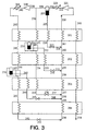
- FIG 3 illustrates another embodiment of the invention wherein a single heat exchanger and more than one compressor is used for the refrigeration circuit.
- a multi-stage compressor in place of the multiple compressors illustrated in Figure 3.
- multicomponent refrigerant fluid 220 comprising at least two components having different volatilities, is compressed by passage through compressor 221 to a first pressure.
- Compressed multicomponent fluid 222 is cooled of the heat of compression in aftercooler 223 and resulting two phase stream 224 is passed into phase separator 205.
- Liquid from phase separator 205 is passed in stream 225 through heat exchanger 201 wherein it is subcooled to form stream 226.
- Stream 226 is passed through valve 227 and resulting stream 228 is combined with stream 260 in the warming leg of the refrigeration circuit to form stream 261.
- Vapor from phase separator 205 is passed out in stream 229 and a portion 230 is cooled and partially condensed by passage through heat exchanger 201.
- Resulting two phase stream 231 is passed to phase separator 206 and liquid is passed in stream 232 from phase separator 206 through heat exchanger 202 wherein it is subcooled to form stream 233.
- Stream 233 is passed through valve 231 and resulting stream 232 is combined with stream 258 in the warming leg of the refrigeration circuit to form stream 259.
- Vapor from phase separator 206 is passed in stream 233 through heat exchanger 202 wherein it is cooled and resulting stream 234 is further cooled by passage through heat exchanger 203 to form stream 235.
- Stream 235 is passed through valve 236 and resulting stream 237 is combined with stream 256 in the warming leg of the refrigeration circuit to form stream 257.
- Remaining portion 238 of vapor stream 229 is further compressed to a second pressure, greater than the first pressure, by passage through compressor 239 and resulting stream 240 is cooled of the heat of compression by passage through aftercooler 241.
- Resulting stream 242 is cooled by passage through heat exchanger 201 and resulting stream 242 is cooled and partially condensed by passage through heat exchanger 202.
- Resulting two phase stream 244 which is passed to separator 207 wherein it is separated into a liquid portion and a remaining portion.
- Resulting subcooled refrigerant fluid in stream 246 is expanded through valve 247 to generate refrigeration and resulting expanded refrigeration bearing fluid 248 is passed into stream 255 and recycled to compressor 221 in the warming leg of the refrigeration circuit.
- stream 244 is withdrawn from phase separator 207 as vapor stream 250 and passed through heat exchanger 203 and then as stream 251 through heat exchanger 204 wherein it is cooled and preferably completely condensed.
- Resulting, preferably all liquid, stream 252 is expanded through valve 253 to generate refrigeration and resulting refrigeration bearing stream 254 is warmed and vaporized to, inter alia, effect the further cooling of the product fluid.
- Stream 254 is then combined with streams 248, 237, 232 and 228 as was previously describe and then recycled as stream 220 to compressor 221.
- Product fluid 210 which is preferably an industrial gas, is cooled and then further cooled by passage through heat exchangers 201, 202, 203 and 204 by indirect heat exchanger with the vaporizing and/or warming portions of the multicomponent refrigerant fluid as was previously described. Resulting further cooled product fluid 214 is then passed on to a use point and/or to storage. Preferably product fluid 210 is in the gaseous state and further cooled product fluid 214 is in the liquid state.
- the multicomponent refrigerant fluid useful in the practice of this invention contains at least two components.
- the choice of refrigerant components will depend on the refrigeration load versus temperature for the particular process application. Suitable components will be chosen depending upon their normal boiling points, latent heat, and flammability, toxicity, and ozone-depletion potential.
- One preferable embodiment of the multicomponent refrigerant fluid useful in the practice of this invention comprises at least one component from the group consisting of fluorocarbons, hydrofluorocarbons and fluoroethers and at least one component from the group consisting of fluorocarbons, hydrofluorocarbons, fluoroethers and atmospheric gases.
- Another preferable embodiment of the multicomponent refrigerant fluid useful in the practice of this invention comprises at least two components from the group consisting of fluorocarbons, hydrofluorocarbons and fluoroethers and at least one atmospheric gas.
- Another preferable embodiment of the multicomponent refrigerant fluid useful in the practice of this invention comprises at least two components from the group consisting of fluorocarbons, hydrofluorocarbons and fluoroethers, and at least two atmospheric gases.
- Another preferable embodiment of the multicomponent refrigerant fluid useful in the practice of this invention comprises at least one fluoroether and at least one component from the group consisting of fluorocarbons, hydrofluorocarbons, fluoroethers and atmospheric gases.
- the multicomponent refrigerant fluid consists solely of fluorocarbons. In another preferred embodiment the multicomponent refrigerant fluid consists solely of fluorocarbons and hydrofluorocarbons. In another preferred embodiment the multicomponent refrigerant fluid consists solely of fluorocarbons and atmospheric gases. In another preferred embodiment the multicomponent refrigerant fluid consists solely of fluorocarbons, hydrofluorocarbons and fluoroethers. In another preferred embodiment the multicomponent refrigerant fluid consists solely of fluorocarbons, fluoroethers and atmospheric gases.
- the multicomponent refrigerant fluid useful in the practice of this invention may contain other components such as hydrochlorofluorocarbons and/or hydrocarbons, preferably the multicomponent refrigerant fluid contains no hydrochlorofluorocarbons. In another preferred embodiment of the invention the multicomponent refrigerant fluid contains no hydrocarbons, and most preferably the multicomponent refrigerant fluid contains neither hydrochlorofluorocarbons nor hydrocarbons. Most preferably the multicomponent refrigerant fluid is non-toxic, non-flammable and non-ozone-depleting and most preferably every component of the multicomponent refrigerant fluid is either a fluorocarbon, hydrofluorocarbon, fluoroether or atmospheric gas.
- the invention is particularly advantageous for use in efficiently reaching cryogenic temperatures from ambient temperatures.
- Tables 1-5 list preferred examples of multicomponent refrigerant fluid mixtures useful in the practice of this invention. The concentration ranges given in Tables 1-5 are in mole percent.
- each of the two or more components of the refrigerant mixture has a normal boiling point which differs by at least 5 degrees Kelvin, more preferably by at least 10 degrees Kelvin, and most preferably by at least 20 degrees Kelvin, from the normal boiling point of every other component in that refrigerant mixture. This enhances the effectiveness of providing refrigeration over a wide temperature range, particularly one which encompasses cryogenic temperatures.
- the normal boiling point of the highest boiling component of the multicomponent refrigerant fluid is at least 50°K, preferably at least 100°K, most preferably at least 200°K, greater than the normal boiling point of the lowest boiling component of the multicomponent refrigerant fluid.
- the components and their concentrations which make up the multicomponent refrigerant fluid useful in the practice of this invention are such as to form a variable load multicomponent refrigerant fluid and preferably maintain such a variable load characteristic throughout the whole temperature range of the method of the invention. This markedly enhances the efficiency with which the refrigeration can be generated and utilized over such a wide temperature range.
- the defined preferred group of components has an added benefit in that they can be used to form fluid mixtures which are non-toxic, non-flammable and low or non-ozone-depleting. This provides additional advantages over conventional refrigerants which typically are toxic, flammable and/or ozone-depleting.
- One preferred variable load multicomponent refrigerant fluid useful in the practice of this invention which is non-toxic, non-flammable and non-ozone-depleting comprises two or more components from the group consisting of C 5 F 12 , CHF 2 -O-C 2 HF 4 , C 4 HF 9 , C 3 H 3 F 5 , C 2 F 5 -O-CH 2 F, C 3 H 2 F 6 , CHF 2 -O-CHF 2 , C 4 F 10 , CF 3 -O-C 2 H 2 F 3 , C 3 HF 7 , CH 2 F-O-CF 3 , C 2 H 2 F 4 , CHF 2 -O-CF 3, C 3 F 8 , C 2 HF 5 , CF 3 -O-CF 3 , C 2 F 6 , CHF 3 , CF 4 , O 2 , Ar, N 2 , Ne and He.
Abstract
Description
- This invention relates generally to the cooling of product fluid and is particularly useful for the liquefaction of industrial gas wherein the gas is brought from ambient temperature to a cryogenic temperature to effect the liquefaction.
- Cooling of fluids such as for the liquefaction of industrial gases is an important step which is used in many operations. In the case of the liquefaction of industrial gas, typically the industrial gas is liquefied by indirect heat exchange with a refrigerant. Such a system, while working well for providing refrigeration over a relatively small temperature range from ambient, is not as efficient when refrigeration over a large temperature range, such as from ambient to a cryogenic temperature, is required. One way this inefficiency has been addressed is to use a liquefaction scheme with multiple circuits wherein each circuit serves to reduce the temperature of the industrial gas until the requisite cryogenic condensing temperature is reached. However, such multiple circuit industrial gas liquefiers may be complicated to operate.
- A conventional single circuit liquefier system is much less complicated than a multiple circuit liquefier but such a system imposes very stringent requirements on the selection of the refrigerant. One way of addressing this inflexibility problem is to use a multicomponent refrigerant fluid instead of the single component refrigerant conventionally used in cooling or liquefying circuits. However, even with the use of a multicomponent refrigerant fluid in a conventional single circuit system , it is difficult to carry out the cooling and/or liquefaction efficiently, especially over a large temperature range, such as from ambient temperature to a cryogenic temperature as would be necessary for the liquefaction of an industrial gas.
- Accordingly, it is an object of this invention to provide an improved method for carrying out cooling of a fluid, such as for liquefying an industrial gas, which employs a multicomponent refrigerant fluid.
- The above and other objects, which will become apparent to those skilled in the art upon a reading of this disclosure, are attained by the present invention which is:
- A method for cooling a product fluid comprising:
- (A) compressing a multicomponent refrigerant fluid comprising at least two components having different volatilities;
- (B) partially condensing the compressed multicomponent refrigerant fluid and separating the resulting partially condensed multicomponent refrigerant fluid into a liquid portion and a remaining portion;
- (C) expanding the liquid portion to generate refrigeration and vaporizing the expanded liquid portion by indirect heat exchange with product fluid to produce cooled product fluid; and
- (D) further cooling at least some of the remaining portion, expanding the further cooled remaining portion to generate refrigeration, and warming the expanded remaining portion by indirect heat exchange with cooled product fluid to produce further cooled product fluid.
-
- As used herein the term "subcooling" means cooling a liquid to be at a temperature lower than that liquid's saturation temperature for the existing pressure.
- As used herein the term "normal boiling point" means the boiling temperature at 1 standard atmosphere pressure, i.e. 14.696 pounds per square inch absolute.
- As used herein the term "indirect heat exchange" means the bringing of fluids into heat exchange relation without any physical contact or intermixing of the fluids with each other.
- As used herein the term "expansion" means to effect a reduction in pressure.
- As used herein the terms "turboexpansion" and "turboexpander" means respectively method and apparatus for the flow of high pressure fluid through a turbine to reduce the pressure and the temperature of the fluid thereby generating refrigeration.
- As used herein the term "non-toxic" means not posing an acute or chronic hazard when handled in accordance with acceptable exposure limits.
- As used herein the term "non-flammable" means either having no flash point or a very high flash point of at least 600°K.
- As used herein the term "non-ozone-depleting" means having zero-ozone depleting potential, i.e. having no chlorine, bromine or iodine atoms.
- As used herein the term "variable load refrigerant" means a mixture of two or more components in proportions such that the liquid phase of those components undergoes a continuous and increasing temperature change between the bubble point and the dew point of the mixture. The bubble point of the mixture is the temperature, at a given pressure, wherein the mixture is all in the liquid phase but addition of heat will initiate formation of a vapor phase in equilibrium with the liquid phase. The dew point of the mixture is the temperature, at a given pressure, wherein the mixture is all in the vapor phase but extraction of heat will initiate formation of a liquid phase in equilibrium with the vapor phase. Hence, the temperature region between the bubble point and the dew point of the mixture is the region wherein both liquid and vapor phases coexist in equilibrium. In the practice of this invention the temperature differences between the bubble point and the dew point for the variable load refrigerant is at least 10°K, preferably at least 20°K and most preferably at least 50°K.
- As used herein the term "fluorocarbon" means one of the following: tetrafluoromethane (CF4), perfluoroethane (C2F6), perfluoropropane (C3F8), perfluorobutane (C4F10), perfluoropentane (C5F12), perfluoroethene (C2F4), perfluoropropene (C3F6), perfluorobutene (C4F8), perfluoropentene (C5F10), hexafluorocyclopropane (cyclo-C3F6) and octafluorocyclobutane (cyclo-C4F8).
- As used herein the term "hydrofluorocarbon" means one of the following: fluoroform (CHF3), pentafluoroethane (C2HF5), tetrafluoroethane (C2H2F4), heptafluoropropane (C3HF7), hexafluoropropane (C3H2F6), pentafluoropropane (C3H3F5), tetrafluoropropane (C3H4F4), nonafluorobutane (C4HF9), octafluorobutane (C4H2F8), undecafluoropentane (C5HF11), methyl fluoride (CH3F), difluoromethane (CH2F2), ethyl fluoride (C2H5F), difluoroethane (C2H4F2), trifluoroethane (C2H3F3), difluoroethene (C2H2F2),trifluoroethene (C2HF3), fluoroethene (C2H3F), pentafluoropropene (C3HF5), tetrafluoropropene (C3H2F4), trifluoropropene (C3H3F3), difluoropropene (C3H4F2), heptafluorobutene (C4HF7), hexafluorobutene (C4H2F6) and nonafluoropentene (C5HF9).
- As used herein the term "fluoroether" means one of the following: trifluoromethyoxy-perfluoromethane (CF3-O-CF3), difluoromethoxy-perfluoromethane (CHF2-O-CF3), fluoromethoxy-perfluoromethane (CH2F-O-CF3), difluoromethoxy-difluoromethane (CHF2-O-CHF2), difluoromethoxy-perfluoroethane (CHF2-O-C2F5), difluoromethoxy-1,2,2,2-tetrafluoroethane (CHF2-O-C2HF4), difluoromethoxy-1,1,2,2-tetrafluoroethane (CHF2-O-C2HF4), perfluoroethoxy-fluoromethane (C2F5-O-CH2F), perfluoromethoxy-1,1,2-trifluoroethane (CF3-O-C2H2F3), perfluoromethoxy-1,2,2-trifluoroethane (CF3O-C2H2F3), cyclo-1,1,2 2-tetrafluoropropylether (cyclo-C3H2F4-O-), cyclo-1,1,3,3-tetrafluoropropylether (cyclo-C3H2F4-O-), perfluoromethoxy-1,1,2 2-tetrafluoroethane (CF3-O-C2HF4),cyclo-1,1,2,3,3-pentafluoropropylether (cyclo-C3H5-O-),perfluoromethoxy-perfluoroacetone (CF3-0-CF2-O-CF3), perfluoromethoxy-perfluoroethane (CF3-O-C2F5), perfluoromethoxy-1,2,2,2-tetrafluoroethane (CF3-O-C2HF4), perfluoromethoxy-2,2,2-trifluoroethane (CF3-O-C2H2F3), cyclo-perfluoromethoxy-perfluoroacetone (cyclo-CF2-O-CF2-O-CF2-) and cyclo-perfluoropropylether (cyclo-C3F6-O).
- As used herein the term "atmospheric gas" means one of the following: nitrogen (N2), argon (Ar), krypton (Kr), xenon (Xe), neon (Ne), carbon dioxide (CO2), oxygen (O2) and helium (He).
- As used herein the term "low-ozone-depleting" means having an ozone depleting potential less than 0.15 as defined by the Montreal Protocol convention wherein dichlorofluoromethane (CCl2F2) has an ozone depleting potential of 1.0.
- As used herein the term "industrial gas" means nitrogen, oxygen, argon, hydrogen, helium, carbon dioxide, carbon monoxide, methane and fluid mixtures containing two or more thereof.
- As used herein the term "cryogenic temperature" means a temperature of 150°K or less.
- As used herein the term "refrigeration" means the capability to reject heat from a subambient temperature system to the surrounding atmosphere.
-
- Figure 1 is a schematic flow diagram of one preferred embodiment of the internal recycle cooling system of this invention.
- Figure 2 is a schematic flow diagram of another preferred embodiment of the internal recycle cooling system of the invention employing product recycle.
- Figure 3 is a schematic flow diagram of another preferred embodiment of the internal recycle cooling system of the invention employing multiple compressors.
-
- The invention comprises, in general, the use of a mixed refrigerant to efficiently provide refrigeration over a very large temperature range, such as from ambient temperature to a cryogenic temperature. Such refrigeration can be effectively employed for the liquefaction of industrial gases, which calls for such a wide temperature range, without the need for employing complicated multiple refrigeration circuits.
- In the practice of this invention, multicomponent refrigerant fluid is partially condensed and then separated into liquid and vapor, with the liquid containing a majority of and preferably most of the least volatile component of the multicomponent refrigerant fluid. The liquid does not continue to the end of the cooling leg of the cooling circuit, but rather is recycled to the compression, with or without subcooling, thereby transferring its refrigeration to the product fluid for cooling. The vapor, containing the more volatile component(s) of the multicomponent refrigerant fluid, continues to be cooled, and generally condensed to the end of the cooling leg of the circuit, and then is used to transfer refrigeration to the product fluid at a colder temperature, thus improving the overall efficiency of the cooling circuit.
- The invention will be described in greater detail with reference to the Drawings. Referring now to Figure 1,
multicomponent refrigerant fluid 60, comprising at least two components having different volatilities, is compressed by passage throughcompressor 30 to a pressure generally within the range of from 100 to 600 pounds per square inch absolute (psia). The compression may be through a single stage or through multiple stages. Preferably the compression ratio, i.e. the ratio of the pressure of compressedmulticomponent refrigerant fluid 61 to that offluid 60 is within the range of from 3 to 15 and most preferably exceeds 5. The compressedmulticomponent refrigerant fluid 61 is cooled of the heat of compression inaftercooler 5 to formstream 62. In theevent compressor 30 is an oil lubricated compressor,stream 62 may be passed toseparator 10 wherein any oil instream 62 is separated and recycled tocompressor 60 as shown byline 64,valve 91 andline 92. - Compressed multicomponent refrigerant fluid is passed, as shown by
line 63, throughheat exchanger 1 wherein it is partially condensed by indirect heat exchange inheat exchanger 1 with warming multicomponent refrigerant fluid as will be more fully discussed below, and resulting partially condensed multicomponent refrigerant fluid 51 is passed tophase separator 11 wherein it is separated into a liquid portion and a remaining portion.Liquid portion 86, containing at least a majority of and preferably most of or substantially all of the highest boiling or least volatile component of the multicomponent refrigerant fluid, is expanded throughvalve 87 to generate refrigeration and resulting expandedrefrigeration bearing fluid 88 is passed into the return or warming leg of the cooling circuit. It is then passed in stream 89 toheat exchanger 1 wherein it is vaporized, to, inter alia, effect the cooling of product fluid, and then instream 90 recycled back tocompressor 30. - Some liquid from
phase separator 11 instream 66 may be passed throughflow control valve 67 to formstream 68 which is combined withvapor stream 65 fromphase separator 11 to formremaining portion 69 which may be all vapor or may be a two phase stream. This remaining portion is passed throughheat exchanger 2 wherein it is cooled and preferably partially condenses by indirect heat exchange with warming multicomponent refrigerant fluid and the resulting cooled remaining portion is expanded to generate refrigeration and then warmed by indirect heat exchange with product fluid at a colder temperature than the heat exchange of the product fluid with the internally recycled liquid portion. In the embodiment illustrated in Figure 1 partially condensedstream 70 fromheat exchanger 2 is passed intophase separator 12 and separated into a remaining vapor portion and a remaining liquid portion. Remaining liquid portion is passed out fromphase separator 12 inline 81, expanded throughvalve 82 to generate refrigeration, and resulting expandedrefrigeration bearing fluid 83 is passed into the return or warming leg of the cooling circuit. It is then passed instream 84 toheat exchanger 1 wherein it is vaporized to, inter alia, cool the product fluid and then fromheat exchanger 2 instream 85 is combined withstream 88 to form stream 89 for recycle tocompressor 30. - Some liquid from
phase separator 12 instream 72 may be passed throughflow control valve 73 to formstream 74 which is combined withremaining vapor portion 71 fromphase separator 12 to formstream 75 which may be all vapor or may be a two phase stream.Stream 75 is passed throughheat exchanger 3 wherein it is cooled and preferably completely condensed by indirect heat exchange with warming multicomponent refrigerant fluid. Resultingstream 76 is expanded throughvalve 77 to generate refrigeration and resultingrefrigeration bearing stream 78 is warmed and preferably vaporized in the warming leg of the cooling circuit by passage throughheat exchangers streams stream 80 is combined withstream 83 to formstream 84 for recycle to the compressor. -
Product fluid 93, which may be industrial gas such as nitrogen or oxygen, is cooled by passage throughheat exchanger 1 by indirect heat exchange with vaporizing liquid portion as was previously described. Resulting cooledproduct fluid 94 is further cooled by indirect heat exchange with remaining portion. In the embodiment illustrated in Figure 1 the further cooling is carried out by passage throughheat exchangers piping line 97. Preferably theproduct fluid 93 is in the gaseous state and the further cooledproduct fluid 97 is in the liquid state. - Figure 2 illustrates another embodiment of the invention wherein the liquid portion of the refrigerant fluid is subcooled prior to being expanded. The embodiment illustrated in Figure 2 also illustrates the case where the compressor is not oil lubricated so that the oil separation step illustrated in Figure 1 is not required.
- Referring now to Figure 2, multicomponent
refrigerant fluid 160, comprising at least two components having different volatilities, is compressed by passage throughcompressor 130 to a pressure generally within the range of from 100 to 1000 psia. The compression may be through a single stage or through multiple stages. Preferably the compression ratio is within the range of from 3 to 15, and most preferably exceeds 5. The compressedmulticomponent fluid 161 is cooled of the heat of compression inaftercooler 104 to form twophase stream 162 which is passed toseparator 110 wherein it is separated into a liquid portion and a remaining portion.Liquid portion 164, containing at least a majority of and preferably most of or substantially all of the highest boiling or least volatile component of the multicomponent refrigerant fluid, is subcooled by passage throughheat exchanger 101 by indirect heat exchange with warming multicomponent refrigerant fluid as will be more fully described below. Resulting subcooled multicomponentrefrigerant fluid 170 is expanded throughvalve 171 to generate refrigeration and resulting expandedrefrigeration bearing fluid 172 is passed into the return or warming leg of the cooling circuit. It is then passed instream 181 toheat exchanger 101 wherein it is vaporized to, inter alia, effect the cooling of product fluid and then recycled instream 160 tocompressor 130. - Remaining portion is withdrawn from
phase separator 110 asvapor stream 163 and passed throughheat exchanger 101 wherein it is cooled and partially condensed to form twophase stream 165.Stream 165 is passed intophase separator 111 for separation into liquid and vapor. The liquid part of the remaining portion is passed fromseparator 111 instream 167 toheat exchanger 102 wherein it is subcooled by indirect heat exchange with warming multicomponent refrigerant fluid. Resultingsubcooled stream 173 is expanded throughvalve 174 to generate refrigeration and resulting expandedrefrigeration bearing fluid 175 is passed into the return leg of the cooling circuit. It is then passed instream 179 throughheat exchanger 102 wherein it is vaporized to, inter alia, effect the further cooling of the product fluid, and then passed instreams heat exchanger 101 for further heat exchange and recycled instream 160 tocompressor 130. - The vapor part of the remaining portion is passed from
separator 111 instream 166 toheat exchanger 102 wherein it is cooled and preferably partially condensed to formstream 168, which is then passed throughheat exchanger 103 wherein it is further cooled and preferably totally condensed. Resulting, preferably all liquid,stream 169 is expanded throughvalve 176 to generate refrigeration and resultingrefrigeration bearing stream 177 is warmed and preferably at least partially vaporized in the warming leg of the cooling or refrigeration circuit by passage throughheat exchanger 103. Resultingstream 178 is combined withstream 175 to formaforesaid stream 179 and, as previously described, passed throughheat exchangers stream 160 tocompressor 130. -
Product fluid 182, which is preferably an industrial gas, is compressed by passage throughcompressor 145 and cooled of the heat of compression inaftercooler 146 to formstream 191 which is cooled by passage throughheat exchanger 101 by indirect heat exchange with vaporizing liquid portion as was previously described. Resulting cooledproduct fluid 183 is further cooled by indirect heat exchange with remaining portion. In the embodiment illustrated in Figure 2 the further cooling is carried out by passage throughheat exchangers piping 184 to produce further cooledproduct 185 which is passed throughvalve 186 to form twophase stream 187. -
Stream 187 is passed intophase separator 188 wherein it is separated into vapor and liquid fluids. Liquid fluid is withdrawn fromseparator 188 asstream 189 and passed on as further cooled product fluid to a use point and/or to storage. Vapor fluid is withdrawn fromphase separator 188 asstream 190, warmed by passage throughheat exchangers stream 182 to form combinedstream 191 for the cooling and further cooling throughheat exchangers - Figure 3 illustrates another embodiment of the invention wherein a single heat exchanger and more than one compressor is used for the refrigeration circuit. Alternatively, one may employ a multi-stage compressor in place of the multiple compressors illustrated in Figure 3. Referring now to Figure 3, multicomponent
refrigerant fluid 220, comprising at least two components having different volatilities, is compressed by passage throughcompressor 221 to a first pressure. Compressedmulticomponent fluid 222 is cooled of the heat of compression inaftercooler 223 and resulting twophase stream 224 is passed intophase separator 205. - Liquid from
phase separator 205 is passed instream 225 throughheat exchanger 201 wherein it is subcooled to formstream 226.Stream 226 is passed throughvalve 227 and resultingstream 228 is combined withstream 260 in the warming leg of the refrigeration circuit to formstream 261. Vapor fromphase separator 205 is passed out instream 229 and aportion 230 is cooled and partially condensed by passage throughheat exchanger 201. Resulting twophase stream 231 is passed to phaseseparator 206 and liquid is passed instream 232 fromphase separator 206 throughheat exchanger 202 wherein it is subcooled to formstream 233.Stream 233 is passed throughvalve 231 and resultingstream 232 is combined withstream 258 in the warming leg of the refrigeration circuit to formstream 259. Vapor fromphase separator 206 is passed instream 233 throughheat exchanger 202 wherein it is cooled and resultingstream 234 is further cooled by passage throughheat exchanger 203 to formstream 235.Stream 235 is passed throughvalve 236 and resultingstream 237 is combined withstream 256 in the warming leg of the refrigeration circuit to formstream 257. - Remaining portion 238 of
vapor stream 229 is further compressed to a second pressure, greater than the first pressure, by passage throughcompressor 239 and resultingstream 240 is cooled of the heat of compression by passage throughaftercooler 241. Resultingstream 242 is cooled by passage throughheat exchanger 201 and resultingstream 242 is cooled and partially condensed by passage throughheat exchanger 202. Resulting twophase stream 244 which is passed toseparator 207 wherein it is separated into a liquid portion and a remaining portion.Liquid portion 245, containing at least a majority of and preferably most of or substantially all of the highest boiling or least volatile component of the multicomponent refrigerant fluid, is subcooled by traverse ofheat exchanger 203 by indirect heat exchange with warming multicomponent refrigerant fluid as will be more fully described below. Resulting subcooled refrigerant fluid instream 246 is expanded throughvalve 247 to generate refrigeration and resulting expandedrefrigeration bearing fluid 248 is passed intostream 255 and recycled tocompressor 221 in the warming leg of the refrigeration circuit. - The remaining portion of
stream 244 is withdrawn fromphase separator 207 asvapor stream 250 and passed throughheat exchanger 203 and then asstream 251 throughheat exchanger 204 wherein it is cooled and preferably completely condensed. Resulting, preferably all liquid,stream 252 is expanded throughvalve 253 to generate refrigeration and resultingrefrigeration bearing stream 254 is warmed and vaporized to, inter alia, effect the further cooling of the product fluid.Stream 254 is then combined withstreams stream 220 tocompressor 221. -
Product fluid 210, which is preferably an industrial gas, is cooled and then further cooled by passage throughheat exchangers product fluid 214 is then passed on to a use point and/or to storage. Preferablyproduct fluid 210 is in the gaseous state and further cooledproduct fluid 214 is in the liquid state. - The multicomponent refrigerant fluid useful in the practice of this invention contains at least two components. The choice of refrigerant components will depend on the refrigeration load versus temperature for the particular process application. Suitable components will be chosen depending upon their normal boiling points, latent heat, and flammability, toxicity, and ozone-depletion potential.
- One preferable embodiment of the multicomponent refrigerant fluid useful in the practice of this invention comprises at least one component from the group consisting of fluorocarbons, hydrofluorocarbons and fluoroethers and at least one component from the group consisting of fluorocarbons, hydrofluorocarbons, fluoroethers and atmospheric gases.
- Another preferable embodiment of the multicomponent refrigerant fluid useful in the practice of this invention comprises at least two components from the group consisting of fluorocarbons, hydrofluorocarbons and fluoroethers and at least one atmospheric gas.
- Another preferable embodiment of the multicomponent refrigerant fluid useful in the practice of this invention comprises at least two components from the group consisting of fluorocarbons, hydrofluorocarbons and fluoroethers, and at least two atmospheric gases.
- Another preferable embodiment of the multicomponent refrigerant fluid useful in the practice of this invention comprises at least one fluoroether and at least one component from the group consisting of fluorocarbons, hydrofluorocarbons, fluoroethers and atmospheric gases.
- In one preferred embodiment the multicomponent refrigerant fluid consists solely of fluorocarbons. In another preferred embodiment the multicomponent refrigerant fluid consists solely of fluorocarbons and hydrofluorocarbons. In another preferred embodiment the multicomponent refrigerant fluid consists solely of fluorocarbons and atmospheric gases. In another preferred embodiment the multicomponent refrigerant fluid consists solely of fluorocarbons, hydrofluorocarbons and fluoroethers. In another preferred embodiment the multicomponent refrigerant fluid consists solely of fluorocarbons, fluoroethers and atmospheric gases.
- Although the multicomponent refrigerant fluid useful in the practice of this invention may contain other components such as hydrochlorofluorocarbons and/or hydrocarbons, preferably the multicomponent refrigerant fluid contains no hydrochlorofluorocarbons. In another preferred embodiment of the invention the multicomponent refrigerant fluid contains no hydrocarbons, and most preferably the multicomponent refrigerant fluid contains neither hydrochlorofluorocarbons nor hydrocarbons. Most preferably the multicomponent refrigerant fluid is non-toxic, non-flammable and non-ozone-depleting and most preferably every component of the multicomponent refrigerant fluid is either a fluorocarbon, hydrofluorocarbon, fluoroether or atmospheric gas.
- The invention is particularly advantageous for use in efficiently reaching cryogenic temperatures from ambient temperatures. Tables 1-5 list preferred examples of multicomponent refrigerant fluid mixtures useful in the practice of this invention. The concentration ranges given in Tables 1-5 are in mole percent.
COMPONENT CONCENTRATION RANGE C5F12 5-25 C4F10 0-15 C3F8 10-40 C2F6 0-30 CF4 10-50 Ar 0-40 N2 10-80 Ne 0-10 He 0-10 COMPONENT CONCENTRATION RANGE C3H3F5 5-25 C4F10 0-15 C3F8 10-40 CHF3 0-30 CF4 10-50 Ar 0-40 N2 10-80 Ne 0-10 He 0-10 COMPONENT CONCENTRATION RANGE C3H3F5 5-25 C3H2F6 0-15 C2H2F4 5-20 C2HF5 5-20 C2F6 0-30 CF4 10-50 Ar 0-40 N2 10-80 Ne 0-10 He 0-10 COMPONENT CONCENTRATION RANGE CHF2-O-C2HF4 5-25 C4F10 0-15 CF3-O-CHF2 10-40 CF3-O-CF3 0-20 C2F6 0-30 CF4 10-50 Ar 0-40 N2 10-80 Ne 0-10 He 0-10 COMPONENT CONCENTRATION RANGE C3H3F5 5-25 C3H2F6 0-15 CF3-O-CHF3 10-40 CHF3 0-30 CF4 0-25 Ar 0-40 N2 10-80 Ne 0-10 He 0-10 - The invention is especially useful for providing refrigeration over a wide temperature range, particularly one which encompasses cryogenic temperatures. In a preferred embodiment of the invention each of the two or more components of the refrigerant mixture has a normal boiling point which differs by at least 5 degrees Kelvin, more preferably by at least 10 degrees Kelvin, and most preferably by at least 20 degrees Kelvin, from the normal boiling point of every other component in that refrigerant mixture. This enhances the effectiveness of providing refrigeration over a wide temperature range, particularly one which encompasses cryogenic temperatures. In a particularly preferred embodiment of the invention, the normal boiling point of the highest boiling component of the multicomponent refrigerant fluid is at least 50°K, preferably at least 100°K, most preferably at least 200°K, greater than the normal boiling point of the lowest boiling component of the multicomponent refrigerant fluid.
- The components and their concentrations which make up the multicomponent refrigerant fluid useful in the practice of this invention are such as to form a variable load multicomponent refrigerant fluid and preferably maintain such a variable load characteristic throughout the whole temperature range of the method of the invention. This markedly enhances the efficiency with which the refrigeration can be generated and utilized over such a wide temperature range. The defined preferred group of components has an added benefit in that they can be used to form fluid mixtures which are non-toxic, non-flammable and low or non-ozone-depleting. This provides additional advantages over conventional refrigerants which typically are toxic, flammable and/or ozone-depleting.
- One preferred variable load multicomponent refrigerant fluid useful in the practice of this invention which is non-toxic, non-flammable and non-ozone-depleting comprises two or more components from the group consisting of C5F12, CHF2-O-C2HF4, C4HF9, C3H3F5, C2F5-O-CH2F, C3H2F6, CHF2-O-CHF2, C4F10, CF3-O-C2H2F3, C3HF7, CH2F-O-CF3, C2H2F4, CHF2-O-CF3, C3F8, C2HF5, CF3-O-CF3, C2F6, CHF3, CF4, O2, Ar, N2, Ne and He. Although the invention has been described in detail with reference to certain preferred embodiments, those skilled in the art will recognize that there are other embodiments of the invention within the spirit and the scope of the claims. For example, one or more of the expansion valves used with the illustrated embodiments could be replaced by turboexpanders for generating refrigeration.
Claims (10)
- A method for cooling a product fluid comprising:(A) compressing a multicomponent refrigerant fluid comprising at least two components having different volatilities;(B) partially condensing the compressed multicomponent refrigerant fluid and separating the resulting partially condensed multicomponent refrigerant fluid into a liquid portion and a remaining portion;(C) expanding the liquid portion to generate refrigeration and vaporizing the expanded liquid portion by indirect heat exchange with product fluid to produce cooled product fluid; and(D) further cooling at least some of the remaining portion, expanding the further cooled remaining portion to generate refrigeration, and warming the expanded remaining portion by indirect heat exchange with cooled product fluid to produce further cooled product fluid.
- The method of claim 1 wherein the liquid portion is subcooled prior to being expanded.
- The method of claim 1 wherein the cooling of the remaining portion causes the remaining portion to be partially condensed, the partially condensed remaining portion is separated into a remaining vapor portion and a remaining liquid portion, and the remaining liquid portion is expanded to generate refrigeration and vaporized by indirect heat exchange with cooled product fluid to produce further cooled product fluid.
- The method of claim 3 wherein the remaining vapor portion is condensed, the resulting condensed remaining vapor portion is expanded to generate refrigeration, and the resulting condensed remaining vapor portion is vaporized by indirect heat exchange with further cooled product fluid.
- The method of claim 1 wherein further cooled product fluid is expanded and a vapor portion of the expanded further cooled product is warmed by indirect heat exchange with cooling product fluid.
- The method of claim 1 wherein the multicomponent refrigerant fluid is compressed to a first pressure, a portion of the first pressure fluid is warmed by indirect heat exchange with product fluid, and another portion of the first pressure fluid is further compressed to a second pressure greater than said first pressure prior to the partial condensation of step (B).
- The method of claim 1 wherein the multicomponent refrigerant fluid comprises at least one component from the group consisting of fluorocarbons, hydrofluorocarbons and fluoroethers and at least one component from the group consisting of fluorocarbons, hydrofluorocarbons, fluoroethers and atmospheric gases.
- The method of claim 1 wherein the multicomponent refrigerant fluid comprises at least two components from the group consisting of fluorocarbons, hydrofluorocarbons and fluoroethers and at least one atmospheric gas.
- The method of claim 1 wherein the multicomponent refrigerant fluid comprises at least one fluoroether and at least one component from the group consisting of fluorocarbons, hydrofluorocarbons, fluoroethers and atmospheric gases.
- The method of claim 1 wherein the normal boiling point of the highest boiling component of the multicomponent refrigerant fluid is at least 50°K greater than the normal boiling point of the lowest boiling component of the multicomponent refrigerant fluid.
Applications Claiming Priority (2)
| Application Number | Priority Date | Filing Date | Title |
|---|---|---|---|
| US222815 | 1981-01-12 | ||
| US09/222,815 US6065305A (en) | 1998-12-30 | 1998-12-30 | Multicomponent refrigerant cooling with internal recycle |
Publications (2)
| Publication Number | Publication Date |
|---|---|
| EP1016841A2 true EP1016841A2 (en) | 2000-07-05 |
| EP1016841A3 EP1016841A3 (en) | 2001-03-21 |
Family
ID=22833811
Family Applications (1)
| Application Number | Title | Priority Date | Filing Date |
|---|---|---|---|
| EP99126065A Withdrawn EP1016841A3 (en) | 1998-12-30 | 1999-12-28 | Multicomponent refrigerant cooling with internal recycle |
Country Status (6)
| Country | Link |
|---|---|
| US (1) | US6065305A (en) |
| EP (1) | EP1016841A3 (en) |
| KR (1) | KR20000048443A (en) |
| CN (1) | CN1263243A (en) |
| BR (1) | BR9905996A (en) |
| CA (1) | CA2293206C (en) |
Families Citing this family (44)
| Publication number | Priority date | Publication date | Assignee | Title |
|---|---|---|---|---|
| EP0998539B2 (en) * | 1997-07-15 | 2013-10-16 | E.I. Du Pont De Nemours And Company | Refrigerant compositions |
| US7258813B2 (en) * | 1999-07-12 | 2007-08-21 | E.I. Du Pont De Nemours And Company | Refrigerant composition |
| US6298688B1 (en) | 1999-10-12 | 2001-10-09 | Air Products And Chemicals, Inc. | Process for nitrogen liquefaction |
| US6308531B1 (en) | 1999-10-12 | 2001-10-30 | Air Products And Chemicals, Inc. | Hybrid cycle for the production of liquefied natural gas |
| US6266977B1 (en) | 2000-04-19 | 2001-07-31 | Air Products And Chemicals, Inc. | Nitrogen refrigerated process for the recovery of C2+ Hydrocarbons |
| EP2988076B8 (en) * | 2000-05-30 | 2019-09-25 | Edwards Vacuum, LLC | A low temperature refrigeration system |
| EP1295070B1 (en) | 2000-06-28 | 2005-12-14 | Helix Technology Corporation | Nonflammable mixed refrigerants (mr) for use with very low temperature throttle-cycle refrigeration systems |
| US6327865B1 (en) | 2000-08-25 | 2001-12-11 | Praxair Technology, Inc. | Refrigeration system with coupling fluid stabilizing circuit |
| US6357257B1 (en) | 2001-01-25 | 2002-03-19 | Praxair Technology, Inc. | Cryogenic industrial gas liquefaction with azeotropic fluid forecooling |
| US6425250B1 (en) | 2001-02-08 | 2002-07-30 | Praxair Technology, Inc. | System for providing cryogenic refrigeration using an upstream pulse tube refrigerator |
| US6415611B1 (en) | 2001-02-22 | 2002-07-09 | Praxair Technology, Inc. | Cryogenic refrigeration system using magnetic refrigerator forecooling |
| US6494054B1 (en) * | 2001-08-16 | 2002-12-17 | Praxair Technology, Inc. | Multicomponent refrigeration fluid refrigeration system with auxiliary ammonia cascade circuit |
| US6438994B1 (en) | 2001-09-27 | 2002-08-27 | Praxair Technology, Inc. | Method for providing refrigeration using a turboexpander cycle |
| US7478540B2 (en) * | 2001-10-26 | 2009-01-20 | Brooks Automation, Inc. | Methods of freezeout prevention and temperature control for very low temperature mixed refrigerant systems |
| US6427483B1 (en) | 2001-11-09 | 2002-08-06 | Praxair Technology, Inc. | Cryogenic industrial gas refrigeration system |
| US6553772B1 (en) | 2002-05-09 | 2003-04-29 | Praxair Technology, Inc. | Apparatus for controlling the operation of a cryogenic liquefier |
| US6666046B1 (en) | 2002-09-30 | 2003-12-23 | Praxair Technology, Inc. | Dual section refrigeration system |
| GB0223724D0 (en) | 2002-10-11 | 2002-11-20 | Rhodia Organique Fine Ltd | Refrigerant compositions |
| US6640557B1 (en) * | 2002-10-23 | 2003-11-04 | Praxair Technology, Inc. | Multilevel refrigeration for high temperature superconductivity |
| KR100469537B1 (en) * | 2002-11-19 | 2005-02-02 | 주식회사 오페론 | Cryogenic multi-refrigerating system |
| US6591632B1 (en) | 2002-11-19 | 2003-07-15 | Praxair Technology, Inc. | Cryogenic liquefier/chiller |
| PL208354B1 (en) * | 2002-11-29 | 2011-04-29 | Du Pont | Chiller refrigerants |
| US7163051B2 (en) * | 2003-08-28 | 2007-01-16 | Praxair Technology, Inc. | Heat exchanger distributor for multicomponent heat exchange fluid |
| EP1771525B1 (en) * | 2004-01-28 | 2014-08-13 | Brooks Automation, Inc. | Refrigeration cycle utilizing a mixed inert component refrigerant |
| US7134296B2 (en) * | 2004-10-13 | 2006-11-14 | Praxair Technology, Inc. | Method for providing cooling for gas liquefaction |
| US20220389297A1 (en) | 2005-03-04 | 2022-12-08 | The Chemours Company Fc, Llc | Compositions comprising a fluoroolefin |
| US7569170B2 (en) | 2005-03-04 | 2009-08-04 | E.I. Du Pont De Nemours And Company | Compositions comprising a fluoroolefin |
| US7708903B2 (en) | 2005-11-01 | 2010-05-04 | E.I. Du Pont De Nemours And Company | Compositions comprising fluoroolefins and uses thereof |
| US7563384B2 (en) * | 2006-07-28 | 2009-07-21 | Honeywell International Inc. | Essentially non-flammable low global warming compositions |
| BRPI0802382B1 (en) * | 2008-06-18 | 2020-09-15 | Universidade Federal De Santa Catarina - Ufsc | REFRIGERATION SYSTEM |
| US20100154469A1 (en) * | 2008-12-19 | 2010-06-24 | Chevron U.S.A., Inc. | Process and system for liquefaction of hydrocarbon-rich gas stream utilizing three refrigeration cycles |
| CN101988771B (en) * | 2009-07-30 | 2013-01-23 | 阜新金昊空压机有限公司 | Nitrogen cooling device for preventing fire-extinguishing in high-temperature environment |
| US9441877B2 (en) | 2010-03-17 | 2016-09-13 | Chart Inc. | Integrated pre-cooled mixed refrigerant system and method |
| FR2966577B1 (en) * | 2010-10-22 | 2012-10-26 | Air Liquide | METHOD AND DEVICE FOR COOLING / LIQUEFACTION AT LOW TEMPERATURE |
| FR2979419B1 (en) * | 2011-08-30 | 2018-03-30 | Arkema France | SUPERCRITICAL HEAT TRANSFER FLUIDS BASED ON TETRAFLUOROPROPENE |
| US11408673B2 (en) | 2013-03-15 | 2022-08-09 | Chart Energy & Chemicals, Inc. | Mixed refrigerant system and method |
| CA3140415A1 (en) | 2013-03-15 | 2014-09-18 | Chart Energy & Chemicals, Inc. | Mixed refrigerant system and method |
| US11428463B2 (en) | 2013-03-15 | 2022-08-30 | Chart Energy & Chemicals, Inc. | Mixed refrigerant system and method |
| EP2799797A3 (en) * | 2013-05-02 | 2015-11-11 | Ballast Nedam International Product Management B.v | Method and system for at least partially liquefying methane containing gas |
| GB2535383B (en) | 2013-07-30 | 2016-10-19 | Mexichem Amanco Holding Sa | Heat transfer compositions |
| GB201501598D0 (en) | 2015-01-30 | 2015-03-18 | Mexichem Fluor Sa De Cv | Compositions |
| AR105277A1 (en) | 2015-07-08 | 2017-09-20 | Chart Energy & Chemicals Inc | MIXED REFRIGERATION SYSTEM AND METHOD |
| GB2571569A (en) * | 2018-03-02 | 2019-09-04 | Linde Ag | Cooling system |
| CN116075674A (en) * | 2021-01-15 | 2023-05-05 | 普和希控股公司 | Refrigerating circuit and refrigerating device |
Citations (5)
| Publication number | Priority date | Publication date | Assignee | Title |
|---|---|---|---|---|
| DE2049181A1 (en) * | 1970-10-07 | 1972-04-13 | Liquid Gas Anlagen Union GmbH, 5480 Remagen | Refrigeration cycle - with expansion of low boiling fraction of mixtu through turbine |
| EP0117793A1 (en) * | 1983-02-08 | 1984-09-05 | L'air Liquide, Societe Anonyme Pour L'etude Et L'exploitation Des Procedes Georges Claude | Fluid cooling process and plant, in particular for liquefying natural gas |
| WO1997011138A1 (en) * | 1995-09-21 | 1997-03-27 | Goble George H | Drop-in substitutes for dichlorodifluoromethane refrigerant |
| US5713211A (en) * | 1995-10-20 | 1998-02-03 | Minnesota Mining And Manufacturing Company | Hydrofluoroethers as low temperature refrigerants |
| WO1998057108A1 (en) * | 1997-06-12 | 1998-12-17 | Costain Oil, Gas & Process Limited | Two-staged refrigeration cycle using a multiconstituant refrigerant |
Family Cites Families (13)
| Publication number | Priority date | Publication date | Assignee | Title |
|---|---|---|---|---|
| US3677019A (en) * | 1969-08-01 | 1972-07-18 | Union Carbide Corp | Gas liquefaction process and apparatus |
| US3690114A (en) * | 1969-11-17 | 1972-09-12 | Judson S Swearingen | Refrigeration process for use in liquefication of gases |
| US3733845A (en) * | 1972-01-19 | 1973-05-22 | D Lieberman | Cascaded multicircuit,multirefrigerant refrigeration system |
| US3932154A (en) * | 1972-06-08 | 1976-01-13 | Chicago Bridge & Iron Company | Refrigerant apparatus and process using multicomponent refrigerant |
| US3768273A (en) * | 1972-10-19 | 1973-10-30 | Gulf & Western Industries | Self-balancing low temperature refrigeration system |
| US3992167A (en) * | 1975-04-02 | 1976-11-16 | Union Carbide Corporation | Low temperature refrigeration process for helium or hydrogen mixtures using mixed refrigerant |
| DE3244143A1 (en) * | 1982-11-29 | 1984-05-30 | Linde Ag, 6200 Wiesbaden | METHOD FOR GAS DISASSEMBLY |
| DE3313171A1 (en) * | 1983-04-12 | 1984-10-18 | Linde Ag, 6200 Wiesbaden | METHOD AND DEVICE FOR PRODUCING PURE CO |
| US5157925A (en) * | 1991-09-06 | 1992-10-27 | Exxon Production Research Company | Light end enhanced refrigeration loop |
| US5441658A (en) * | 1993-11-09 | 1995-08-15 | Apd Cryogenics, Inc. | Cryogenic mixed gas refrigerant for operation within temperature ranges of 80°K- 100°K |
| US5450728A (en) * | 1993-11-30 | 1995-09-19 | Air Products And Chemicals, Inc. | Recovery of volatile organic compounds from gas streams |
| DE69523437T2 (en) * | 1994-12-09 | 2002-06-20 | Kobe Steel Ltd | Gas liquefaction plant and method |
| US5746066A (en) * | 1996-09-17 | 1998-05-05 | Manley; David B. | Pre-fractionation of cracked gas or olefins fractionation by one or two mixed refrigerant loops and cooling water |
-
1998
- 1998-12-30 US US09/222,815 patent/US6065305A/en not_active Expired - Lifetime
-
1999
- 1999-12-24 CA CA002293206A patent/CA2293206C/en not_active Expired - Fee Related
- 1999-12-28 BR BR9905996-7A patent/BR9905996A/en active Search and Examination
- 1999-12-28 KR KR1019990063283A patent/KR20000048443A/en not_active Application Discontinuation
- 1999-12-28 CN CN99127425A patent/CN1263243A/en active Pending
- 1999-12-28 EP EP99126065A patent/EP1016841A3/en not_active Withdrawn
Patent Citations (5)
| Publication number | Priority date | Publication date | Assignee | Title |
|---|---|---|---|---|
| DE2049181A1 (en) * | 1970-10-07 | 1972-04-13 | Liquid Gas Anlagen Union GmbH, 5480 Remagen | Refrigeration cycle - with expansion of low boiling fraction of mixtu through turbine |
| EP0117793A1 (en) * | 1983-02-08 | 1984-09-05 | L'air Liquide, Societe Anonyme Pour L'etude Et L'exploitation Des Procedes Georges Claude | Fluid cooling process and plant, in particular for liquefying natural gas |
| WO1997011138A1 (en) * | 1995-09-21 | 1997-03-27 | Goble George H | Drop-in substitutes for dichlorodifluoromethane refrigerant |
| US5713211A (en) * | 1995-10-20 | 1998-02-03 | Minnesota Mining And Manufacturing Company | Hydrofluoroethers as low temperature refrigerants |
| WO1998057108A1 (en) * | 1997-06-12 | 1998-12-17 | Costain Oil, Gas & Process Limited | Two-staged refrigeration cycle using a multiconstituant refrigerant |
Also Published As
| Publication number | Publication date |
|---|---|
| CN1263243A (en) | 2000-08-16 |
| BR9905996A (en) | 2001-03-27 |
| EP1016841A3 (en) | 2001-03-21 |
| CA2293206A1 (en) | 2000-06-30 |
| US6065305A (en) | 2000-05-23 |
| CA2293206C (en) | 2003-08-19 |
| KR20000048443A (en) | 2000-07-25 |
Similar Documents
| Publication | Publication Date | Title |
|---|---|---|
| US6065305A (en) | Multicomponent refrigerant cooling with internal recycle | |
| US6041621A (en) | Single circuit cryogenic liquefaction of industrial gas | |
| US6041620A (en) | Cryogenic industrial gas liquefaction with hybrid refrigeration generation | |
| EP1016844B1 (en) | Multiple circuit cryogenic liquefaction of industrial gas with multicomponent refrigerant | |
| EP1016843B1 (en) | Method for carrying out subambient temperature, especially cryogenic, separation using refrigeration from a multicomponent refrigerant fluid | |
| CA2293153C (en) | Method for providing refrigeration | |
| US6426019B1 (en) | Variable load refrigeration system particularly for cryogenic temperatures | |
| US6881354B2 (en) | Multicomponent refrigerant fluids for low and cryogenic temperatures | |
| US6112550A (en) | Cryogenic rectification system and hybrid refrigeration generation | |
| EP1136774A1 (en) | Cryogenic air separation process for producing liquid oxygen | |
| US6357257B1 (en) | Cryogenic industrial gas liquefaction with azeotropic fluid forecooling | |
| US6125656A (en) | Cryogenic rectification method for producing nitrogen gas and liquid nitrogen | |
| EP1098151A1 (en) | Cryogenic air separation process using multicomponent refrigerant | |
| MXPA99011687A (en) | Method for carrying out subambient temperature, especially cryogenic, separation using refrigeration from a multicomponent refrigerant fluid |
Legal Events
| Date | Code | Title | Description |
|---|---|---|---|
| PUAI | Public reference made under article 153(3) epc to a published international application that has entered the european phase |
Free format text: ORIGINAL CODE: 0009012 |
|
| AK | Designated contracting states |
Kind code of ref document: A2 Designated state(s): DE ES FR GB IT |
|
| AX | Request for extension of the european patent |
Free format text: AL;LT;LV;MK;RO;SI |
|
| PUAL | Search report despatched |
Free format text: ORIGINAL CODE: 0009013 |
|
| AK | Designated contracting states |
Kind code of ref document: A3 Designated state(s): AT BE CH CY DE DK ES FI FR GB GR IE IT LI LU MC NL PT SE |
|
| AX | Request for extension of the european patent |
Free format text: AL;LT;LV;MK;RO;SI |
|
| 17P | Request for examination filed |
Effective date: 20010330 |
|
| AKX | Designation fees paid |
Free format text: DE ES FR GB IT |
|
| 17Q | First examination report despatched |
Effective date: 20020327 |
|
| STAA | Information on the status of an ep patent application or granted ep patent |
Free format text: STATUS: THE APPLICATION IS DEEMED TO BE WITHDRAWN |
|
| 18D | Application deemed to be withdrawn |
Effective date: 20020807 |