EP1016529A1 - An ink jet printer with cleaning mechanism having a wiper blade and transducer and method of assembling the printer - Google Patents
An ink jet printer with cleaning mechanism having a wiper blade and transducer and method of assembling the printer Download PDFInfo
- Publication number
- EP1016529A1 EP1016529A1 EP99204268A EP99204268A EP1016529A1 EP 1016529 A1 EP1016529 A1 EP 1016529A1 EP 99204268 A EP99204268 A EP 99204268A EP 99204268 A EP99204268 A EP 99204268A EP 1016529 A1 EP1016529 A1 EP 1016529A1
- Authority
- EP
- European Patent Office
- Prior art keywords
- wiper
- print head
- cleaning mechanism
- contaminant
- cleaning
- Prior art date
- Legal status (The legal status is an assumption and is not a legal conclusion. Google has not performed a legal analysis and makes no representation as to the accuracy of the status listed.)
- Withdrawn
Links
Images


Classifications
-
- B—PERFORMING OPERATIONS; TRANSPORTING
- B41—PRINTING; LINING MACHINES; TYPEWRITERS; STAMPS
- B41J—TYPEWRITERS; SELECTIVE PRINTING MECHANISMS, i.e. MECHANISMS PRINTING OTHERWISE THAN FROM A FORME; CORRECTION OF TYPOGRAPHICAL ERRORS
- B41J2/00—Typewriters or selective printing mechanisms characterised by the printing or marking process for which they are designed
- B41J2/005—Typewriters or selective printing mechanisms characterised by the printing or marking process for which they are designed characterised by bringing liquid or particles selectively into contact with a printing material
- B41J2/01—Ink jet
- B41J2/135—Nozzles
- B41J2/165—Preventing or detecting of nozzle clogging, e.g. cleaning, capping or moistening for nozzles
- B41J2/16517—Cleaning of print head nozzles
- B41J2/16535—Cleaning of print head nozzles using wiping constructions
- B41J2/16544—Constructions for the positioning of wipers
-
- B—PERFORMING OPERATIONS; TRANSPORTING
- B41—PRINTING; LINING MACHINES; TYPEWRITERS; STAMPS
- B41J—TYPEWRITERS; SELECTIVE PRINTING MECHANISMS, i.e. MECHANISMS PRINTING OTHERWISE THAN FROM A FORME; CORRECTION OF TYPOGRAPHICAL ERRORS
- B41J2/00—Typewriters or selective printing mechanisms characterised by the printing or marking process for which they are designed
- B41J2/005—Typewriters or selective printing mechanisms characterised by the printing or marking process for which they are designed characterised by bringing liquid or particles selectively into contact with a printing material
- B41J2/01—Ink jet
- B41J2/135—Nozzles
- B41J2/165—Preventing or detecting of nozzle clogging, e.g. cleaning, capping or moistening for nozzles
- B41J2/16517—Cleaning of print head nozzles
- B41J2/16535—Cleaning of print head nozzles using wiping constructions
- B41J2/16541—Means to remove deposits from wipers or scrapers
-
- B—PERFORMING OPERATIONS; TRANSPORTING
- B41—PRINTING; LINING MACHINES; TYPEWRITERS; STAMPS
- B41J—TYPEWRITERS; SELECTIVE PRINTING MECHANISMS, i.e. MECHANISMS PRINTING OTHERWISE THAN FROM A FORME; CORRECTION OF TYPOGRAPHICAL ERRORS
- B41J2/00—Typewriters or selective printing mechanisms characterised by the printing or marking process for which they are designed
- B41J2/005—Typewriters or selective printing mechanisms characterised by the printing or marking process for which they are designed characterised by bringing liquid or particles selectively into contact with a printing material
- B41J2/01—Ink jet
- B41J2/17—Ink jet characterised by ink handling
- B41J2/18—Ink recirculation systems
- B41J2/185—Ink-collectors; Ink-catchers
-
- B—PERFORMING OPERATIONS; TRANSPORTING
- B41—PRINTING; LINING MACHINES; TYPEWRITERS; STAMPS
- B41J—TYPEWRITERS; SELECTIVE PRINTING MECHANISMS, i.e. MECHANISMS PRINTING OTHERWISE THAN FROM A FORME; CORRECTION OF TYPOGRAPHICAL ERRORS
- B41J2/00—Typewriters or selective printing mechanisms characterised by the printing or marking process for which they are designed
- B41J2/005—Typewriters or selective printing mechanisms characterised by the printing or marking process for which they are designed characterised by bringing liquid or particles selectively into contact with a printing material
- B41J2/01—Ink jet
- B41J2/135—Nozzles
- B41J2/165—Preventing or detecting of nozzle clogging, e.g. cleaning, capping or moistening for nozzles
- B41J2/16517—Cleaning of print head nozzles
- B41J2002/16567—Cleaning of print head nozzles using ultrasonic or vibrating means
Definitions
- This invention generally relates to ink jet printer apparatus and methods and more particularly relates to an ink jet printer with cleaning mechanism having a wiper blade and transducer, and method of assembling the printer.
- An ink jet printer produces images on a receiver by ejecting ink droplets onto the receiver in an imagewise fashion.
- the advantages of non-impact, low-noise, low energy use, and low cost operation in addition to the capability of the printer to print on plain paper are largely responsible for the wide acceptance of ink jet printers in the marketplace.
- continuous ink jet printers utilize electrostatic charging tunnels placed close to the point where ink droplets are being ejected in the form of a stream. Selected ones of the droplets are electrically charged by the charging tunnels. The charged droplets are deflected downstream by the presence of deflector plates that have a predetermined electric potential difference between them. A gutter may be used to intercept the charged droplets, while the uncharged droplets are free to strike the recording medium.
- a pressurization actuator is used to produce the ink jet droplet.
- either one of two types of actuators may be used.
- These two types of actuators are heat actuators and piezoelectric actuators.
- heat actuators a heater placed at a convenient location heats the ink and a quantity of the ink will phase change into a gaseous steam bubble and raise the internal ink pressure sufficiently for an ink droplet to be expelled to the recording medium.
- piezoelectric actuators a piezoelectric material is used, which piezoelectric material possess piezoelectric properties such that an electric field is produced when a mechanical stress is applied.
- Inks for high speed ink jet printers whether of the "continuous” or “piezoelectric” type, have a number of special characteristics.
- the ink should incorporate a nondrying characteristic, so that drying of ink in the ink ejection chamber is hindered or slowed to such a state that by occasional spitting of ink droplets, the cavities and corresponding orifices are kept open.
- the addition of glycol facilitates free flow of ink through the ink jet chamber.
- the ink jet print head is exposed to the environment where the ink jet printing occurs.
- the previously mentioned orifices are exposed to many kinds of air born particulates.
- Particulate debris may accumulate on surfaces formed around the orifices and may accumulate in the orifices and chambers themselves. That is, the ink may combine with such particulate debris to form an interference burr that blocks the orifice or that alters surface wetting to inhibit proper formation of the ink droplet.
- the ink may simply dry-out and form hardened deposits on the print head surface and in the ink channels.
- the particulate debris and deposits should be cleaned from the surface and orifice to restore proper droplet formation. In the prior art, this cleaning is commonly accomplished by brushing, wiping, spraying, vacuum suction or spitting of ink through the orifice.
- inks used in ink jet printers can be said to have the following problems: the inks tend to dry-out in and around the orifices resulting in clogging of the orifices; the wiping of the orifice plate causes wear on plate and wiper and the wiper itself produces particles that clog the orifice; cleaning cycles are time consuming and slow productivity of ink jet printers.
- printing rate declines in large format printing where frequent cleaning cycles interrupt the printing of an image. Printing rate also declines in the case when a special printing pattern is initiated to compensate for plugged or badly performing orifices.
- Ink jet print head cleaners are known.
- a wiping system for ink jet print heads is disclosed in U.S. Patent 5,614,930 titled "Orthogonal Rotary Wiping System For Inkjet Printheads" issued March 25,1997 in the name of William S. Osborne et al.
- This patent discloses a rotary service station that has a wiper supporting tumbler. The tumbler rotates to wipe the print head along a length of linearly aligned nozzle.
- a wiper scraping system scrapes the wipers to clean the wipers.
- Osborne et al. do not disclose use of an external solvent to assist cleaning and also does not disclose complete removal of the external solvent.
- an object of the present invention is to provide a suitable ink jet printer with cleaning mechanism having a wiper blade and transducer, and method of assembling the printer, which cleaning mechanism is capable of simultaneously cleaning the print head surface and ink channels.
- the invention resides in an ink jet printer, comprising a print head having a surface thereon and an ink channel therein; and a cleaning mechanism associated with said print head and adapted to simultaneously clean contaminant from the surface and the ink channel, said cleaning mechanism including a wiper having a plurality of wicking channels therein alignable with the surface, the wicking channels communicating with a passageway formed in said cleaning mechanism; and a sonic vibrator connected to said wiper for vibrating said wiper, so that said vibrator cleans the contaminant from the surface.
- an ink jet printer comprises a print head having a surface thereon surrounding a plurality of ink ejection orifices.
- the orifices are in communication with respective ones of a plurality of ink channels formed in the print head.
- a solvent delivering wiper has a plurality of internal passageways formed therethrough alignable with the surface which delivers a liquid solvent cleaning agent to the surface to flush contaminant from the surface. In this manner, contaminant residing on the surface is entrained in the solvent while the wiper flushes contaminant from the surface.
- a transducer is integrated in the wiper blade, which is capable of serving three functions.
- the transducer can be used to produce a mechanical vibration in the wiper, it can be used as the means to pump the cleaning solvent, or it can be used to ultrasonically energize the cleaning solvent.
- the solvent delivering wiper has a second passageway alignable with the surface which vacuums solvent and entrained contaminant from the surface.
- wicking channels or groves are provided on the beveled edge of the wiper blade.
- the previously described wiper and transducer will here-in-below be referred to as a cleaning block.
- a piping circuit is provided for filtering the particulate matter from the solvent and for recirculating clean solvent to the surface of the print head.
- a translation mechanism is connected to the wiper for translating, the wiper across the print head surface.
- the translation mechanism may comprise a lead-screw threadably engaging the wiper.
- a displacement mechanism is connected to the wiper for displacing the wiper to a position proximate the surface of the print head to enable cleaning of the ink channels and the surface of the print head.
- the cleaning block, associated translation mechanism, and plumbing will be referred to hereinbelow as a cleaning mechanism.
- a feature of the present invention is the provision of a cleaning mechanism associated with the print head, which cleaning mechanism is adapted to simultaneously clean contaminant from the print head surface and ink channels.
- An advantage of the present invention is that cleaning time is reduced because the print head surface and ink channels are cleaned simultaneously.
- a first embodiment ink jet printer for printing an image 20 (shown in phantom) on a receiver 30 (also shown in phantom), which may be a reflective-type receiver (e.g., paper) or a transmissive-type receiver (e.g., transparency).
- Receiver 30 is supported on a platen roller 40 capable of being rotated by a platen roller motor 50 engaging platen roller 40.
- platen roller motor 50 rotates platen roller 40
- receiver 30 will advance in a direction illustrated by a first arrow 55.
- Platen roller 40 is adapted to pivot outwardly about a pivot shaft 57 along an arc 59 for reasons disclosed hereinbelow. Many designs for feeding paper for printing are possible.
- Another mechanism utilizes a first set of feed rollers to dispose receiver onto a plate for printing. A second set of feed rollers remove the receiver when printing is completed.
- printer 10 also comprises a reciprocating print head 60 disposed adjacent to platen roller 40.
- Print head 60 includes a plurality of ink channels 70 formed therein (only six of which are shown), each channel 70 terminating in a channel outlet 75.
- each channel 70 which is adapted to hold an ink body 77 therein, is defined by a pair of oppositely disposed parallel side walls 79a and 79b.
- Print head 60 may further include a cover plate 80 having a plurality of orifices 90 formed therethrough colinearly aligned with respective ones of channel outlets 75, such that each orifice 90 faces receiver 30.
- a surface 95 of cover plate 80 surrounds all orifices 90 and also faces receiver 30.
- print head 60 may be a "piezoelectric ink jet" print head formed of a piezoelectric material, such as lead zirconium titanate (PZT).
- PZT lead zirconium titanate
- Such a piezoelectric material is mechanically responsive to electrical stimuli so that side walls 79a/b simultaneously inwardly deform when electrically stimulated.
- volume of channel 70 decreases to squeeze ink droplet 100 from channel 70 and through orifice 90.
- a transport mechanism is connected to print head 60 for reciprocating print head 60 between a first position 115a thereof and a second position 115b (shown in phantom).
- transport mechanism 110 reciprocates print head 60 in direction of a second arrow 117.
- Print head 60 slidably engages an elongate guide rail 120, which guides print head 60 parallel to platen roller 40 while print head 60 is reciprocated.
- Transport mechanism 110 also comprises a drive belt 130 attached to print head 60 for reciprocating print head 60 between first position 115a and second position 115b, as described presently.
- a reversible drive belt motor 140 engages belt 130, such that belt 130 reciprocates in order that print head 60 reciprocates with respect to platen 40.
- an encoder strip 150 coupled to print head 60 monitors position of print head 60 as print head 60 reciprocates between first position 115a and second position 115b.
- a controller 160 is connected to platen roller motor 50, drive belt motor 140, encoder strip 150 and print head 60 for controlling operation thereof to suitably form image 20 on receiver 30.
- a controller may be a Model CompuMotor controller available from Parker Hannifin, Incorporated located in Rohnert Park, California, U.S.A.
- particulate matter 165 may have contaminant thereon, such as particulate matter 165.
- Such particulate matter 165 also may partially or completely obstruct orifice 90.
- Particulate matter 165 may be, for example, particles of dirt, dust, metal and/or encrustations of dried ink.
- the contaminant may also be an unwanted film (e.g., grease, oxide, or the like).
- an unwanted film e.g., grease, oxide, or the like.
- ink droplet 105 may be diverted from preferred axis 105 to travel along a non-preferred axis 167 (as shown). If ink droplet 100 travels along non-preferred axis 167, ink droplet 100 will land on receiver 30 in an unintended location. In this manner, such complete or partial obstruction of orifice 90 leads to printing artifacts such as "banding", a highly undesirable result. Also, presence of particulate matter 165 on surface 95 may alter surface wetting and inhibit proper formation of droplet 100. Therefore, it is desirable to clean (i.e., remove) particulate matter 165 to avoid printing artifacts and improper formation of droplet 100.
- first embodiment cleaning block 175 includes a solvent delivering wiper 210 with a transducer 180 mounted atop the wiper.
- Wiper 210 has a first set of multiple internal areaways 220 formed therethrough.
- Solvent delivering wiper 210 is oriented with respect to surface 95 such that first areaways 220 are alignable with surface 95 for reasons disclosed presently.
- first areaways 220 are alignable with surface 95 for delivering a liquid solvent cleaning agent to surface 95 in order to flush particulate matter 165 from surface 95 (as shown).
- particulate matter 165 will be entrained in the solvent as the solvent flushes particulate matter 165 from surface 95.
- Wiper 210 may also include a blade portion 225 integrally formed therewith for lifting contaminant 165 from surface 95 as cleaning wiper blade 210 traverses surface 95 in direction of a third arrow 227.
- the transducer 180 is mounted atop the cleaning wiper blade 210 by any suitable means known in the art, such as by a suitable screw fastener (not shown).
- the transducer has a wire harness 195 extending from it, leading to a controller 190.
- the transducer is driven via the controller, which produces a mechanical vibration in the cleaning wiper blade 210. This mechanical vibration produces a shearing type effect in the blade portion 225 as it transverses the printhead surface 95, which aids in the removal of stubborn particulate matter 165.
- wicking channels 230 and a second set of multiple internal cuts 240 in combination with vacuum pump 290 co-act to remove solvent and particulate matter 165 which may have been left by blade portion 225 as blade portion 225 traverses surface 95 (as shown).
- a second embodiment cleaning block 242 includes a solvent delivering wiper 210 with a transducer 180 mounted internal to the wiper.
- the second embodiment cleaning block 242 serves the same function as first embodiment cleaning block 235 with the only exception being in the placement and functionality of transducer 180.
- the transducer 180 is mounted internal to solvent delivering wiper 210 and serves as an extra means of controlling the solvent flow through first set of multiple internal areaways 220.
- the transducer is activated via controller 190 and wiring harness 195, and is capable of controlling the solvent delivered to the surface 95.
- a third embodiment cleaning block 244 includes a solvent delivering wiper 210, a solvent manifold 200 and transducer 180 mounted behind the solvent manifold.
- the third embodiment cleaning block 244 serves the same function as first embodiment cleaning block 235 and second embodiment 242.
- solvent manifold 200 is attached to the solvent delivering wiper 210 by any suitable means known in the art, such as by a suitable screw fastener (not shown).
- Attached to the rear of manifold 200 is transducer 180 also connected by any suitable means known in the art, such as by a suitable screw fastener (not shown).
- the transducer is connected to and controlled by controller 190 via wiring harness 195. When the transducer is activated, it ultrasonically energizes the solvent in the manifold. The solvent is ejected onto surface 95 and the removal of particulate 165 is enhanced by the energized solvent.
- Fig 8A shows first embodiment cleaning block 175 in a scraping mode defined as having an angle ⁇ less than 90 degrees.
- Fig. 8B shows first embodiment cleaning block 175 in a wiping mode defined as having an angle ⁇ greater than 90 degrees.
- a piping circuit is associated with print head 60 for reasons disclosed momentarily.
- piping circuit 250 includes a first piping segment 260 coupled to first areaway 220 formed through wiper 210.
- a discharge pump 270 is connected to first piping segment 260 for discharging the solvent into first piping segment 260.
- the solvent discharges into first set of areaways 220 formed within the wiper 210 and onto surface 95 while discharge pump 270 discharges the solvent into first piping segment 260.
- the solvent discharged onto surface 95 is chosen such that the solvent also, at least in part, acts as lubricant to lubricate surface 95.
- a second piping segment 280 is coupled to a second set of cuts 240 formed within the wiper 210.
- a vacuum pump 290 is connected to second piping segment 280 for inducing negative pressure (i.e., pressure less than atmospheric pressure) in second piping segment 280.
- negative pressure is induced in second set of cuts 240 and in second piping segment 280.
- the solvent and entrained particulate matter 165 are vacuumed from surface 95 to enter second set of cuts 240.
- first piping segment 260 is coupled to the first set of multiple internal areaways 220 via a passageway internal to solvent manifold 200.
- second piping segment 280 is coupled to the second set of multiple internal cuts 240 via a passageway internal to solvent manifold 200. It should be noted that the two passageways in manifold 200 are unconnected, with one being used for the fresh solvent introduced to the wiper and the other used for the "dirty" solvent sucked from surface 95.
- first piping segment 260 interposed between first piping segment 260 and second piping segment 280 is a solvent supply reservoir 300 having a supply of the solvent therein.
- Discharge pump 270 which is connected to first piping segment 260, draws the solvent from reservoir 300 and discharges the solvent into second areaways 220 by means of first piping circuit 260.
- first piping circuit 260 extends from wiper 210 to reservoir 300.
- vacuum pump 290 which is connected to second piping segment 280, pumps the solvent and particulate matter 165 from print head surface 95 toward reservoir 300.
- circuit 250 defines a recirculation loop for recirculating contaminant-free solvent across surface 95 to efficiently clean surface 95.
- first segment 260 is connected to first segment 260 to first segment 260 to first segment 260 to first segment 260 to first segment 260.
- first valve 314 and second valve 316 are interposed between reservoir 300 and vacuum pump 290. Presence of first valve 314 and second valve 316 make it more convenient to perform maintenance on cleaning mechanism 170. That is, first valve 314 and second valve 316 allow cleaning mechanism 170 to be easily taken out-of service f or maintenance.
- discharge pump 270 is shut-off and first valve 314 is closed.
- Vacuum pump 290 is operated until solvent and particulate matter are substantially evacuated from second piping segment 280.
- second valve 316 is closed and vacuum pump 290 is shut-off.
- saturated filter 310 is replaced with a clean filter 310.
- cleaning mechanism 170 is returned to service substantially in reverse to steps used to take cleaning mechanism 170 out-of service.
- a translation mechanism is connected to cleaning block 175 for translating cleaning block 175 across surface 95 of print head 60.
- translation mechanism 320 comprises an elongate externally threaded lead-screw 330 threadably engaging cleaning block 175.
- Engaging lead-screw 330 is a motor 340 capable of rotating lead-screw 330, so that cleaning block 175, traverses surface 95 as lead-screw 330 rotates.
- cleaning block 175 traverses surface 95 in direction of a fourth arrow 345.
- cleaning block 175 is capable of being translated to any location on lead-screw 330, which preferably extends the length of guide rail 120. Being able to translate cleaning block 175 to any location on lead-screw 330 allows cleaning block 175 to clean print head 60 wherever print head 60 is located on guide rail 120.
- a displacement mechanism 350 for displacing cleaning block 175 to a position proximate surface 95 of print head 60.
- platen roller 40 is disposed adjacent to print head 60 and, unless appropriate steps are taken, will interfere with displacing cleaning block 175 to a position proximate surface 95. Therefore, it is desirable to move platen roller 40 out of interference with cleaning block 175 so that cleaning block 175 can be displaced proximate surface 95. Therefore, according to the first embodiment of printer 10, platen roller 40 is pivoted outwardly about previously mentioned pivot shaft 57 along arc 59. After platen roller 40 has been pivoted, displacement mechanism 350 is operated to displace cleaning block 175 to a position proximate surface 95 to begin removal of particulate matter 165 from ink channel 70 and surface 95.
- Second embodiment ink jet printer 360 capable of simultaneously removing particulate matter 165 from ink channel 70 and surface 95.
- Second embodiment ink jet printer 360 is substantially similar to first embodiment ink jet printer 10, except that platen roller 40 is fixed (i.e., non-pivoting).
- print head 60 pivots about a pivot pin 370 to an upright position (as shown).
- cleaning mechanism 170 is oriented in an upright position (as shown) and displacement mechanism 350 displaces cleaning block 175, so that cleaning block is moved to a location proximate surface 95.
- a third embodiment ink jet printer 400 capable of simultaneously removing particulate matter 165 from ink channel 70 and surface 95.
- Third embodiment ink jet printer 400 is substantially similar to first embodiment ink jet printer 10, except that platen roller 40 is fixed (i.e., non-pivoting).
- print head 60 pivots about pivot pin 370 to an upright position (as shown) and displacement mechanism 350 displaces printer 400 (except for platen roller 40), so that printer 400 is moved to a location proximate cleaning mechanism 170.
- cleaning mechanism 170 is oriented in a fixed upright position (as shown).
- FIG. 13 and 14 there is shown a fourth embodiment ink jet printer 410 capable of simultaneously removing particulate matter 165 from ink channel 70 and surface 95.
- Fourth embodiment ink jet printer 410 is substantially similar to first embodiment ink jet printer 10, except that platen roller 40 is fixed (i.e., non-pivoting) and cleaning assembly 170 is off-set from an end portion of platen roller 40 by a distance "X". Also, according to this third embodiment printer, displacement mechanism 350 displaces printer 410 (except for platen roller 40), so that printer 410 is moved to a location proximate cleaning mechanism 170.
- Second printer 400 is a so-called "page-width" printer capable of printing across width W of receiver 30 without reciprocating across width W. That is, printer 420 comprises print head 60 of length substantially equal to width W. Connected to print head 60 is a carriage 430 adapted to carry print head 60 in direction of first arrow 55. In this regard, carriage 430 slidably engages an elongate slide member 440 extending parallel to receiver 30 in direction of first arrow 55. A print head drive motor 450 is connected to carriage 430 for operating carriage 430, so that carriage 430 slides along slide member 440 in direction of first arrow 55.
- print head 60 As carriage 430 slides along slide member 440 in direction of first arrow 55, print head 60 also travels in direction of first arrow 55 because print head 60 is connected to carriage 430. In this manner, print head 60 is capable of printing a plurality of images 20 (as shown) in a single printing pass along length of receiver 30.
- a first feed roller 460 engages receiver 30 for feeding receiver 30 in direction of first arrow 55 after all images 20 have been printed.
- a first feed roller motor 470 engages first feed roller 460 for rotating first feed roller 460, so that receiver 30 feeds in direction of first arrow 55.
- a second feed roller 480 spaced-apart from first feed roller 460, may also engage receiver 30 for feeding receiver 30 in direction of first arrow 55.
- a second feed roller motor 490 synchronized with first feed roller motor 470, engages second feed roller 480 for rotating second feed roller 480, so that receiver 30 smoothly feeds in direction of first arrow 55.
- a support member such as a stationary flat platen 500, for supporting receiver 30 thereon as receiver feeds from first feed roller 460 to second feed roller 480.
- controller 160 is connected to print head 60, print head drive motor 450, first feed roller motor 470 and second feed roller motor 490 for controlling operation thereof in order to suitably form images 20 on receiver 30.
- displacement mechanism 350 displaces printer 410 (except for feed rollers 460/480 and platen 500), so that printer 410 is moved to a location proximate cleaning mechanism 170.
- the solvent cleaning agent mentioned hereinabove may be any suitable liquid solvent composition, such as water, isopropanol, diethylene glycol, diethylene glycol monobutyl ether, octane, acids and bases, surfactant solutions and any combination thereof.
- suitable liquid solvent compositions such as water, isopropanol, diethylene glycol, diethylene glycol monobutyl ether, octane, acids and bases, surfactant solutions and any combination thereof.
- Complex liquid compositions may also be used, such as microemulsions, micellar surfactant solutions, vesicles and solid particles dispersed in the liquid.
- an advantage of the present invention is that cleaning time is reduced. This is so because surface 95 of print head 60 is cleaned of contaminant simultaneously with cleaning ink channels 70 formed in the print head 60.
- displacement mechanism 350 may be foldable to the upright position from a substantially horizontal position. This configuration of the invention will minimize the external envelope of printer 360 when print head 60 is not being cleaned by cleaning mechanism 170, so that printer 360 can be located in a confined space with limited headroom.
- an ink jet printer with cleaning mechanism having a wiper blade and transducer, and method of assembling the printer, which cleaning mechanism is capable of simultaneously cleaning the print head surface and ink channels.
Abstract
An ink jet printer with cleaning mechanism having a wiper blade
and transducer, and method of assembling same. The printer (10, 360, 400, 410,
420) comprises a print head (60) having a surface (95) thereon surrounding a
plurality of ink ejection orifices (90). The orifices are in communication with
respective ones of a plurality of ink channels (70) formed in the print head. A
cleaning liquid delivering wiper (210) is provided as a means to a clean print head.
Further, a sonic or ultrasonic transducer (180) is provided to energize the wiper
and the cleaning liquid flowing through solvent delivering channels in wiper.
Contaminant (165) residing on the surface is entrained in the cleaning liquid while
the wiper flushes contaminant from the surface. In addition, a piping circuit (250)
is associated with the print head for filtering the particulate matter from the
solvent and for recirculating clean solvent to the surface of the print head.
Description
- This invention generally relates to ink jet printer apparatus and methods and more particularly relates to an ink jet printer with cleaning mechanism having a wiper blade and transducer, and method of assembling the printer.
- An ink jet printer produces images on a receiver by ejecting ink droplets onto the receiver in an imagewise fashion. The advantages of non-impact, low-noise, low energy use, and low cost operation in addition to the capability of the printer to print on plain paper are largely responsible for the wide acceptance of ink jet printers in the marketplace.
- In this regard, "continuous" ink jet printers utilize electrostatic charging tunnels placed close to the point where ink droplets are being ejected in the form of a stream. Selected ones of the droplets are electrically charged by the charging tunnels. The charged droplets are deflected downstream by the presence of deflector plates that have a predetermined electric potential difference between them. A gutter may be used to intercept the charged droplets, while the uncharged droplets are free to strike the recording medium.
- In the case of "on demand" ink jet printers, at every orifice a pressurization actuator is used to produce the ink jet droplet. In this regard, either one of two types of actuators may be used. These two types of actuators are heat actuators and piezoelectric actuators. With respect to heat actuators, a heater placed at a convenient location heats the ink and a quantity of the ink will phase change into a gaseous steam bubble and raise the internal ink pressure sufficiently for an ink droplet to be expelled to the recording medium. With respect to piezoelectric actuators, a piezoelectric material is used, which piezoelectric material possess piezoelectric properties such that an electric field is produced when a mechanical stress is applied. The converse also holds true; that is, an applied electric field will produce a mechanical stress in the material. Some naturally occurring materials possessing this characteristics are quartz and tourmaline. The most commonly produced piezoelectric ceramics are lead zirconate titanate, lead metaniobate, lead titanate, and barium titanate.
- Inks for high speed ink jet printers, whether of the "continuous" or "piezoelectric" type, have a number of special characteristics. For example, the ink should incorporate a nondrying characteristic, so that drying of ink in the ink ejection chamber is hindered or slowed to such a state that by occasional spitting of ink droplets, the cavities and corresponding orifices are kept open. The addition of glycol facilitates free flow of ink through the ink jet chamber.
- Of course, the ink jet print head is exposed to the environment where the ink jet printing occurs. Thus, the previously mentioned orifices are exposed to many kinds of air born particulates. Particulate debris may accumulate on surfaces formed around the orifices and may accumulate in the orifices and chambers themselves. That is, the ink may combine with such particulate debris to form an interference burr that blocks the orifice or that alters surface wetting to inhibit proper formation of the ink droplet. Also, the ink may simply dry-out and form hardened deposits on the print head surface and in the ink channels. The particulate debris and deposits should be cleaned from the surface and orifice to restore proper droplet formation. In the prior art, this cleaning is commonly accomplished by brushing, wiping, spraying, vacuum suction or spitting of ink through the orifice.
- Thus, inks used in ink jet printers can be said to have the following problems: the inks tend to dry-out in and around the orifices resulting in clogging of the orifices; the wiping of the orifice plate causes wear on plate and wiper and the wiper itself produces particles that clog the orifice; cleaning cycles are time consuming and slow productivity of ink jet printers. Moreover, printing rate declines in large format printing where frequent cleaning cycles interrupt the printing of an image. Printing rate also declines in the case when a special printing pattern is initiated to compensate for plugged or badly performing orifices.
- Ink jet print head cleaners are known. A wiping system for ink jet print heads is disclosed in U.S. Patent 5,614,930 titled "Orthogonal Rotary Wiping System For Inkjet Printheads" issued March 25,1997 in the name of William S. Osborne et al. This patent discloses a rotary service station that has a wiper supporting tumbler. The tumbler rotates to wipe the print head along a length of linearly aligned nozzle. In addition, a wiper scraping system scrapes the wipers to clean the wipers. However, Osborne et al. do not disclose use of an external solvent to assist cleaning and also does not disclose complete removal of the external solvent.
- Therefore, an object of the present invention is to provide a suitable ink jet printer with cleaning mechanism having a wiper blade and transducer, and method of assembling the printer, which cleaning mechanism is capable of simultaneously cleaning the print head surface and ink channels.
- With the above object in view, the invention resides in an ink jet printer, comprising a print head having a surface thereon and an ink channel therein; and a cleaning mechanism associated with said print head and adapted to simultaneously clean contaminant from the surface and the ink channel, said cleaning mechanism including a wiper having a plurality of wicking channels therein alignable with the surface, the wicking channels communicating with a passageway formed in said cleaning mechanism; and a sonic vibrator connected to said wiper for vibrating said wiper, so that said vibrator cleans the contaminant from the surface.
- According to an exemplary embodiment of the invention, an ink jet printer comprises a print head having a surface thereon surrounding a plurality of ink ejection orifices. The orifices are in communication with respective ones of a plurality of ink channels formed in the print head. A solvent delivering wiper has a plurality of internal passageways formed therethrough alignable with the surface which delivers a liquid solvent cleaning agent to the surface to flush contaminant from the surface. In this manner, contaminant residing on the surface is entrained in the solvent while the wiper flushes contaminant from the surface. A transducer is integrated in the wiper blade, which is capable of serving three functions. The transducer can be used to produce a mechanical vibration in the wiper, it can be used as the means to pump the cleaning solvent, or it can be used to ultrasonically energize the cleaning solvent. The solvent delivering wiper has a second passageway alignable with the surface which vacuums solvent and entrained contaminant from the surface. To aid in the removal of cleaning solvent and contaminant, wicking channels or groves are provided on the beveled edge of the wiper blade. The previously described wiper and transducer will here-in-below be referred to as a cleaning block. Moreover, a piping circuit is provided for filtering the particulate matter from the solvent and for recirculating clean solvent to the surface of the print head.
- In addition, a translation mechanism is connected to the wiper for translating, the wiper across the print head surface. In this regard, the translation mechanism may comprise a lead-screw threadably engaging the wiper. Moreover, a displacement mechanism is connected to the wiper for displacing the wiper to a position proximate the surface of the print head to enable cleaning of the ink channels and the surface of the print head. The cleaning block, associated translation mechanism, and plumbing will be referred to hereinbelow as a cleaning mechanism.
- A feature of the present invention is the provision of a cleaning mechanism associated with the print head, which cleaning mechanism is adapted to simultaneously clean contaminant from the print head surface and ink channels.
- An advantage of the present invention is that cleaning time is reduced because the print head surface and ink channels are cleaned simultaneously.
- These and other objects, features and advantages of the present invention will become apparent to those skilled in the art upon a reading of the following detailed description when taken in conjunction with the drawings wherein there are shown and described illustrative embodiments of the invention.
- While the specification concludes with claims particularly pointing-out and distinctly claiming the subject matter of the present invention, it is believed the invention will be better understood from the following detailed description when taken in conjunction with the accompanying drawings wherein:
- Figure 1 is a view in plan of a first embodiment ink jet printer, the printer having a reciprocating print head and a pivotable platen roller disposed adjacent the print head;
- Figure 2 is a view in plan of the first embodiment of the printer showing the pivotable platen roller pivoting in an arc outwardly from the print head;
- Figure 3 is a view taken along section line 3-3 of Figure 1, this view showing a cleaning mechanism poised to move to a position adjacent the print head to clean the print head;
- Figure 4 is a view in partial elevation of the print head and adjacent platen roller;
- Figure 5 is a view in elevation of the first embodiment printer, this view showing the cleaning mechanism having been moved into position to clean the print head;
- Figure 6 is a view in perspective of a first embodiment cleaning block belonging to the cleaning mechanism, the first embodiment cleaning block here shown cleaning the print head;
- Figure 7A is an isometric view of the first embodiment cleaning block;
- Figure 7B is an isometric view of the second embodiment cleaning block;
- Figure 7C is an isometric view of the third embodiment cleaning block;
- Figure 8A is a view in vertical section of the first embodiment cleaning block while the first embodiment cleaning block cleans the print head;
- Figure 8B is a view in vertical section of a second embodiment cleaning block while the second embodiment cleaning block cleans the print head;
- Figure 9 is a view in elevation of a second embodiment ink jet printer, this view showing the cleaning mechanism disposed in an upright position and poised to move to a location adjacent the print head to clean the print head, which print head is capable of being pivoted into an upright position;
- Figure 10 is a view in elevation of the second embodiment printer, this view showing the cleaning mechanism having been moved into position to clean the print head not pivoted into an upright position;
- Figure 11 is a view in elevation of a third embodiment ink jet printer, this view showing the print head pivoted into an upright position and poised to move to a location adjacent the upright cleaning mechanism to clean the print head;
- Figure 12 is a view in elevation of the third embodiment printer, this view showing the print head having been moved into position to clean the print head;
- Figure 13 is a view in elevation of a fourth embodiment ink jet printer, this view showing the print head in a horizontal position and poised to move laterally to a location adjacent the cleaning mechanism to clean the print head;
- Figure 14 is a view in elevation of the fourth embodiment printer, this view showing the print head having been moved into position to clean the print head;
- Figure 15 is a view in plan of a fifth embodiment ink jet printer, the printer having a non-reciprocating "page-width" print head;
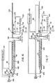
- Figure 16 is a view taken along section line 16-16 of Figure 15, this view showing the print head in a horizontal position and poised to move laterally to a location adjacent the cleaning mechanism to clean the print head; and
- Figure 17 is a view in elevation of the fifth embodiment printer, this view showing the print head having been moved into position to clean the print head.
-
- The present description will be directed in particular to elements forming part of, or cooperating more directly with, apparatus in accordance with the present invention. It is to be understood that elements not specifically shown or described may take various forms well known to those skilled in the art.
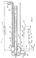
- Therefore, referring to Figs. 1 and 2, there is shown a first embodiment ink jet printer, generally referred to as 10, for printing an image 20 (shown in phantom) on a receiver 30 (also shown in phantom), which may be a reflective-type receiver (e.g., paper) or a transmissive-type receiver (e.g., transparency).
Receiver 30 is supported on aplaten roller 40 capable of being rotated by aplaten roller motor 50 engagingplaten roller 40. Thus, when platenroller motor 50 rotatesplaten roller 40,receiver 30 will advance in a direction illustrated by afirst arrow 55.Platen roller 40 is adapted to pivot outwardly about apivot shaft 57 along anarc 59 for reasons disclosed hereinbelow. Many designs for feeding paper for printing are possible. Another mechanism utilizes a first set of feed rollers to dispose receiver onto a plate for printing. A second set of feed rollers remove the receiver when printing is completed. - Referring to Figs. 1, 3 and 4,
printer 10 also comprises areciprocating print head 60 disposed adjacent to platenroller 40.Print head 60 includes a plurality ofink channels 70 formed therein (only six of which are shown), eachchannel 70 terminating in achannel outlet 75. In addition, eachchannel 70, which is adapted to hold anink body 77 therein, is defined by a pair of oppositely disposedparallel side walls 79a and 79b.Print head 60 may further include acover plate 80 having a plurality oforifices 90 formed therethrough colinearly aligned with respective ones ofchannel outlets 75, such that eachorifice 90 facesreceiver 30. Asurface 95 ofcover plate 80 surrounds allorifices 90 and also facesreceiver 30. Of course, in order to printimage 20 onreceiver 30, anink droplet 100 is released fromink channel 70 throughorifice 90 in direction ofreceiver 30 along apreferred axis 105 normal tosurface 95, so thatdroplet 100 is suitably intercepted byreceiver 30. To achieve this result,print head 60 may be a "piezoelectric ink jet" print head formed of a piezoelectric material, such as lead zirconium titanate (PZT). Such a piezoelectric material is mechanically responsive to electrical stimuli so that side walls 79a/b simultaneously inwardly deform when electrically stimulated. When side walls 79a/b simultaneously inwardly deform, volume ofchannel 70 decreases to squeezeink droplet 100 fromchannel 70 and throughorifice 90. - Referring again to Figs. 1, 3 and 4, a transport mechanism, generally referred to as 110, is connected to print
head 60 for reciprocatingprint head 60 between a first position 115a thereof and asecond position 115b (shown in phantom). In this regard,transport mechanism 110 reciprocatesprint head 60 in direction of asecond arrow 117.Print head 60 slidably engages anelongate guide rail 120, which guidesprint head 60 parallel toplaten roller 40 whileprint head 60 is reciprocated.Transport mechanism 110 also comprises adrive belt 130 attached to printhead 60 for reciprocatingprint head 60 between first position 115a andsecond position 115b, as described presently. In this regard, a reversibledrive belt motor 140 engagesbelt 130, such thatbelt 130 reciprocates in order thatprint head 60 reciprocates with respect toplaten 40. Moreover, anencoder strip 150 coupled toprint head 60 monitors position ofprint head 60 asprint head 60 reciprocates between first position 115a andsecond position 115b. In addition, acontroller 160 is connected toplaten roller motor 50,drive belt motor 140,encoder strip 150 andprint head 60 for controlling operation thereof to suitably formimage 20 onreceiver 30. Such a controller may be a Model CompuMotor controller available from Parker Hannifin, Incorporated located in Rohnert Park, California, U.S.A. - As best seen in Fig. 4, it has been observed that
surface 95 may have contaminant thereon, such asparticulate matter 165. Suchparticulate matter 165 also may partially or completely obstructorifice 90.Particulate matter 165 may be, for example, particles of dirt, dust, metal and/or encrustations of dried ink. The contaminant may also be an unwanted film (e.g., grease, oxide, or the like). Although the description herein refers to particulate matter, it is to be understood that the invention pertains to such unwanted film, as well. Presence ofparticulate matter 165 is undesirable because whenparticulate matter 165 completely obstructsorifice 90,ink droplet 100 is prevented from being ejected fromorifice 90. Also, whenparticulate matter 165 partially obstructsorifice 90, flight ofink droplet 105 may be diverted frompreferred axis 105 to travel along a non-preferred axis 167 (as shown). Ifink droplet 100 travels alongnon-preferred axis 167,ink droplet 100 will land onreceiver 30 in an unintended location. In this manner, such complete or partial obstruction oforifice 90 leads to printing artifacts such as "banding", a highly undesirable result. Also, presence ofparticulate matter 165 onsurface 95 may alter surface wetting and inhibit proper formation ofdroplet 100. Therefore, it is desirable to clean (i.e., remove)particulate matter 165 to avoid printing artifacts and improper formation ofdroplet 100. - Referring to Figs. 3, 5, 6, 7A, 8A and 8B, first
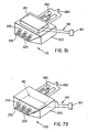
embodiment cleaning block 175 includes a solvent deliveringwiper 210 with atransducer 180 mounted atop the wiper.Wiper 210 has a first set of multipleinternal areaways 220 formed therethrough. Solvent deliveringwiper 210 is oriented with respect to surface 95 such thatfirst areaways 220 are alignable withsurface 95 for reasons disclosed presently. In this regard,first areaways 220 are alignable withsurface 95 for delivering a liquid solvent cleaning agent to surface 95 in order to flushparticulate matter 165 from surface 95 (as shown). Of course,particulate matter 165 will be entrained in the solvent as the solvent flushesparticulate matter 165 fromsurface 95.Wiper 210 may also include ablade portion 225 integrally formed therewith for liftingcontaminant 165 fromsurface 95 ascleaning wiper blade 210 traverses surface 95 in direction of athird arrow 227. Thetransducer 180 is mounted atop thecleaning wiper blade 210 by any suitable means known in the art, such as by a suitable screw fastener (not shown). The transducer has awire harness 195 extending from it, leading to acontroller 190. The transducer is driven via the controller, which produces a mechanical vibration in thecleaning wiper blade 210. This mechanical vibration produces a shearing type effect in theblade portion 225 as it transverses theprinthead surface 95, which aids in the removal of stubbornparticulate matter 165. It may be understood that wickingchannels 230 and a second set of multipleinternal cuts 240 in combination withvacuum pump 290 co-act to remove solvent andparticulate matter 165 which may have been left byblade portion 225 asblade portion 225 traverses surface 95 (as shown). - As best seen in Fig. 7, a second
embodiment cleaning block 242 includes a solvent deliveringwiper 210 with atransducer 180 mounted internal to the wiper. The secondembodiment cleaning block 242 serves the same function as first embodiment cleaning block 235 with the only exception being in the placement and functionality oftransducer 180. In the second embodiment, thetransducer 180 is mounted internal to solvent deliveringwiper 210 and serves as an extra means of controlling the solvent flow through first set of multipleinternal areaways 220. The transducer is activated viacontroller 190 andwiring harness 195, and is capable of controlling the solvent delivered to thesurface 95. - As best seen in Fig. 7C, a third
embodiment cleaning block 244 includes a solvent deliveringwiper 210, asolvent manifold 200 andtransducer 180 mounted behind the solvent manifold. The thirdembodiment cleaning block 244 serves the same function as first embodiment cleaning block 235 andsecond embodiment 242. In the third embodiment,solvent manifold 200 is attached to the solvent deliveringwiper 210 by any suitable means known in the art, such as by a suitable screw fastener (not shown). Attached to the rear ofmanifold 200 istransducer 180 also connected by any suitable means known in the art, such as by a suitable screw fastener (not shown). The transducer is connected to and controlled bycontroller 190 viawiring harness 195. When the transducer is activated, it ultrasonically energizes the solvent in the manifold. The solvent is ejected ontosurface 95 and the removal ofparticulate 165 is enhanced by the energized solvent. - Fig 8A shows first
embodiment cleaning block 175 in a scraping mode defined as having an angle less than 90 degrees. Fig. 8B shows firstembodiment cleaning block 175 in a wiping mode defined as having an angle greater than 90 degrees. - Returning to Figs. 3, 5, 6, 7A, 7B, 8A, and 8B, a piping circuit, generally referred to as 250, is associated with
print head 60 for reasons disclosed momentarily. In this regard, pipingcircuit 250 includes afirst piping segment 260 coupled tofirst areaway 220 formed throughwiper 210. Adischarge pump 270 is connected tofirst piping segment 260 for discharging the solvent intofirst piping segment 260. In this manner, the solvent discharges into first set ofareaways 220 formed within thewiper 210 and ontosurface 95 whiledischarge pump 270 discharges the solvent intofirst piping segment 260. It may be appreciated that the solvent discharged ontosurface 95 is chosen such that the solvent also, at least in part, acts as lubricant to lubricatesurface 95.Surface 95 is lubricated in this manner, so that previously mentionedblade portion 225 will not substantially mar, scar, or otherwisedamage surface 95 and any electrical circuitry which may be present onsurface 95. In addition, asecond piping segment 280 is coupled to a second set ofcuts 240 formed within thewiper 210. Avacuum pump 290 is connected tosecond piping segment 280 for inducing negative pressure (i.e., pressure less than atmospheric pressure) insecond piping segment 280. Thus, negative pressure is induced in second set ofcuts 240 and insecond piping segment 280. As negative pressure is induced onsecond piping segment 280, the solvent and entrainedparticulate matter 165 are vacuumed fromsurface 95 to enter second set ofcuts 240. - Referring now to third
embodiment cleaning block 244, shown in Fig. 7C, the piping circuit generally referred to as 250 is similar to that in the first and second embodiments previously discussed in detail. The difference in the third embodiment is thatfirst piping segment 260 is coupled to the first set of multipleinternal areaways 220 via a passageway internal tosolvent manifold 200. Likewise,second piping segment 280 is coupled to the second set of multipleinternal cuts 240 via a passageway internal tosolvent manifold 200. It should be noted that the two passageways inmanifold 200 are unconnected, with one being used for the fresh solvent introduced to the wiper and the other used for the "dirty" solvent sucked fromsurface 95. - Referring yet again to Figs. 3, 5, 6, 7A, 7B, 7C, 8A, and 8B, interposed between
first piping segment 260 andsecond piping segment 280 is asolvent supply reservoir 300 having a supply of the solvent therein.Discharge pump 270, which is connected tofirst piping segment 260, draws the solvent fromreservoir 300 and discharges the solvent intosecond areaways 220 by means offirst piping circuit 260. Hence, it may be appreciated thatfirst piping circuit 260 extends fromwiper 210 toreservoir 300. In addition,vacuum pump 290, which is connected tosecond piping segment 280, pumps the solvent andparticulate matter 165 fromprint head surface 95 towardreservoir 300. Connected tosecond piping segment 280 and interposed betweenvacuum pump 290 andreservoir 300 is afilter 310 for capturing (i.e., separating-out)particulate matter 165 from the solvent, so that the solvent supply inreservoir 300 is free ofparticulate matter 165. Of course, whenfilter 310 becomes saturated withparticulate matter 165,filter 310 is replaced by an operator ofprinter 10. Thus,circuit 250 defines a recirculation loop for recirculating contaminant-free solvent acrosssurface 95 to efficientlyclean surface 95. In addition, connected tofirst segment 260 is afirst valve 314, whichfirst valve 314 is interposed betweenwiper 210 anddischarge pump 270. Moreover, connected tosecond segment 280 is asecond valve 316, whichsecond valve 316 is interposed betweenreservoir 300 andvacuum pump 290. Presence offirst valve 314 andsecond valve 316 make it more convenient to perform maintenance oncleaning mechanism 170. That is,first valve 314 andsecond valve 316 allowcleaning mechanism 170 to be easily taken out-of service f or maintenance. For example, to replacefilter 310,discharge pump 270 is shut-off andfirst valve 314 is closed.Vacuum pump 290 is operated until solvent and particulate matter are substantially evacuated fromsecond piping segment 280. At this point,second valve 316 is closed andvacuum pump 290 is shut-off. Next, saturatedfilter 310 is replaced with aclean filter 310. Thereafter,cleaning mechanism 170 is returned to service substantially in reverse to steps used to takecleaning mechanism 170 out-of service. - Still referring to Figs. 3, 5, 6, 7A, 8A, and 8B, a translation mechanism, generally referred to as 320, is connected to cleaning block 175 for translating
cleaning block 175 acrosssurface 95 ofprint head 60. In this regard,translation mechanism 320 comprises an elongate externally threaded lead-screw 330 threadably engagingcleaning block 175. Engaging lead-screw 330 is amotor 340 capable of rotating lead-screw 330, so that cleaningblock 175, traverses surface 95 as lead-screw 330 rotates. In this regard, cleaningblock 175 traverses surface 95 in direction of a fourth arrow 345. In addition, cleaningblock 175 is capable of being translated to any location on lead-screw 330, which preferably extends the length ofguide rail 120. Being able to translate cleaning block 175 to any location on lead-screw 330 allows cleaningblock 175 to cleanprint head 60 whereverprint head 60 is located onguide rail 120. Moreover, connected tomotor 340 is adisplacement mechanism 350 for displacingcleaning block 175 to a positionproximate surface 95 ofprint head 60. - Referring now to Figs. 2, 3 and 5,
platen roller 40 is disposed adjacent to printhead 60 and, unless appropriate steps are taken, will interfere with displacingcleaning block 175 to a positionproximate surface 95. Therefore, it is desirable to moveplaten roller 40 out of interference with cleaningblock 175 so that cleaningblock 175 can be displacedproximate surface 95. Therefore, according to the first embodiment ofprinter 10,platen roller 40 is pivoted outwardly about previously mentionedpivot shaft 57 alongarc 59. After platenroller 40 has been pivoted,displacement mechanism 350 is operated to displace cleaningblock 175 to a positionproximate surface 95 to begin removal ofparticulate matter 165 fromink channel 70 andsurface 95. - Turning now to Figs. 9 and 10, there is shown a second embodiment
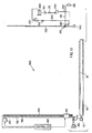
ink jet printer 360 capable of simultaneously removingparticulate matter 165 fromink channel 70 andsurface 95. Second embodimentink jet printer 360 is substantially similar to first embodimentink jet printer 10, except thatplaten roller 40 is fixed (i.e., non-pivoting). Also, according to this second embodiment printer,print head 60 pivots about apivot pin 370 to an upright position (as shown). Moreover,cleaning mechanism 170 is oriented in an upright position (as shown) anddisplacement mechanism 350 displaces cleaningblock 175, so that cleaning block is moved to a locationproximate surface 95. - Referring to Figs. 11 and 12, there is shown a third embodiment
ink jet printer 400 capable of simultaneously removingparticulate matter 165 fromink channel 70 andsurface 95. Third embodimentink jet printer 400 is substantially similar to first embodimentink jet printer 10, except thatplaten roller 40 is fixed (i.e., non-pivoting). Also, according to this third embodiment printer,print head 60 pivots aboutpivot pin 370 to an upright position (as shown) anddisplacement mechanism 350 displaces printer 400 (except for platen roller 40), so thatprinter 400 is moved to a locationproximate cleaning mechanism 170. Moreover,cleaning mechanism 170 is oriented in a fixed upright position (as shown). - Referring to Figs. 13 and 14, there is shown a fourth embodiment
ink jet printer 410 capable of simultaneously removingparticulate matter 165 fromink channel 70 andsurface 95. Fourth embodimentink jet printer 410 is substantially similar to first embodimentink jet printer 10, except thatplaten roller 40 is fixed (i.e., non-pivoting) and cleaningassembly 170 is off-set from an end portion ofplaten roller 40 by a distance "X". Also, according to this third embodiment printer,displacement mechanism 350 displaces printer 410 (except for platen roller 40), so thatprinter 410 is moved to a locationproximate cleaning mechanism 170. - Referring to Figs. 15, 16 and 17, there is shown a fifth embodiment ink jet printer, generally referred to as 420, for printing
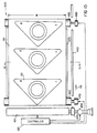
image 20 onreceiver 30.Second printer 400 is a so-called "page-width" printer capable of printing across width W ofreceiver 30 without reciprocating across width W. That is,printer 420 comprisesprint head 60 of length substantially equal to width W. Connected to printhead 60 is acarriage 430 adapted to carryprint head 60 in direction offirst arrow 55. In this regard,carriage 430 slidably engages anelongate slide member 440 extending parallel toreceiver 30 in direction offirst arrow 55. A printhead drive motor 450 is connected tocarriage 430 for operatingcarriage 430, so thatcarriage 430 slides alongslide member 440 in direction offirst arrow 55. Ascarriage 430 slides alongslide member 440 in direction offirst arrow 55,print head 60 also travels in direction offirst arrow 55 becauseprint head 60 is connected tocarriage 430. In this manner,print head 60 is capable of printing a plurality of images 20 (as shown) in a single printing pass along length ofreceiver 30. In addition, afirst feed roller 460 engagesreceiver 30 for feedingreceiver 30 in direction offirst arrow 55 after allimages 20 have been printed. In this regard, a firstfeed roller motor 470 engagesfirst feed roller 460 for rotatingfirst feed roller 460, so thatreceiver 30 feeds in direction offirst arrow 55. Further, asecond feed roller 480, spaced-apart fromfirst feed roller 460, may also engagereceiver 30 for feedingreceiver 30 in direction offirst arrow 55. In this case, a secondfeed roller motor 490, synchronized with firstfeed roller motor 470, engagessecond feed roller 480 for rotatingsecond feed roller 480, so thatreceiver 30 smoothly feeds in direction offirst arrow 55. Interposed betweenfirst feed roller 460 andsecond feed roller 480 is a support member, such as a stationaryflat platen 500, for supportingreceiver 30 thereon as receiver feeds fromfirst feed roller 460 tosecond feed roller 480. Of course, previously mentionedcontroller 160 is connected to printhead 60, printhead drive motor 450, firstfeed roller motor 470 and secondfeed roller motor 490 for controlling operation thereof in order to suitably formimages 20 onreceiver 30. - Still referring to Figs. 15, 16 and 17, according to this
fifth embodiment printer 420,displacement mechanism 350 displaces printer 410 (except forfeed rollers 460/480 and platen 500), so thatprinter 410 is moved to a locationproximate cleaning mechanism 170. - The solvent cleaning agent mentioned hereinabove may be any suitable liquid solvent composition, such as water, isopropanol, diethylene glycol, diethylene glycol monobutyl ether, octane, acids and bases, surfactant solutions and any combination thereof. Complex liquid compositions may also be used, such as microemulsions, micellar surfactant solutions, vesicles and solid particles dispersed in the liquid.
- It may be understood from the teachings hereinabove, that an advantage of the present invention is that cleaning time is reduced. This is so because
surface 95 ofprint head 60 is cleaned of contaminant simultaneously with cleaningink channels 70 formed in theprint head 60. - While the invention has been described with particular reference to its preferred embodiments, it will be understood by those skilled in the art that various changes may be made and equivalents may be substituted for elements of the preferred embodiments without departing from the invention. For example, with respect to the
second embodiment printer 360,displacement mechanism 350 may be foldable to the upright position from a substantially horizontal position. This configuration of the invention will minimize the external envelope ofprinter 360 whenprint head 60 is not being cleaned by cleaningmechanism 170, so thatprinter 360 can be located in a confined space with limited headroom. - Therefore, what is provided is an ink jet printer with cleaning mechanism having a wiper blade and transducer, and method of assembling the printer, which cleaning mechanism is capable of simultaneously cleaning the print head surface and ink channels.
Claims (9)
- An ink jet printer, comprising:(a) a print head (60) having a surface (95) thereon and an ink channel (70) therein; and(b) a cleaning mechanism (170) associated with said print head and adapted to simultaneously clean contaminant (165) from the surface and the ink channel, said cleaning mechanism including:(i) a wiper (210) having a plurality of wicking channels (230) therein alignable with the surface, the wicking channels communicating with a passageway (240) formed in said cleaning mechanism; and(ii) a sonic vibrator (180) connected to said wiper for vibrating said wiper, so that said vibrator cleans the contaminant from the surface.
- The printer of claim 1, wherein said cleaning mechanism comprises a vacuum pump (290) capable of being coupled to the passageway for vacuuming contaminant from the surface, along the wicking channels and through the passageway.
- The printer of claim 1, further comprising a displacement mechanism (350) coupled to said cleaning mechanism for transporting said cleaning mechanism to near the surface of said printhead.
- A cleaning mechanism for cleaning an ink jet print head having a surface thereon and an ink channel therein, comprising:(a) a solvent delivering wiper having a plurality of wicking channels alignable with the surface, the wicking channels in communication with a passageway formed in said wiper;(b) an sonic vibrator connected to said wiper for vibrating said wiper, so that said wiper cleans the contaminant from the surface while said wiper vibrates; and(c) a vacuum pump capable of being coupled to the passageway for vacuuming contaminant from the surface, along the wicking channels and through the passageway.
- A method of assembling an ink jet printer, comprising the steps of:(a) providing a print head having a surface thereon and an ink channel therein; and(b) providing a cleaning mechanism associated with the print head and adapted to simultaneously clean contaminant from the surface and the ink channel, the cleaning mechanism including the steps of:(i) providing a wiper having a plurality of wicking channels therein alignable with the surface, the wicking channels communicating with a passageway formed in the cleaning mechanism; and(ii) connecting a sonic vibrator to the wiper for vibrating the wiper, so that the wiper cleans the contaminant from the surface while the wiper vibrates.
- The method of claim 5, wherein the step of providing a cleaning mechanism comprises the step providing a vacuum pump capable of being coupled to the passageway for vacuuming contaminant from the surface, along the wicking channels and through the passageway.
- The method of claim 5, wherein the step of providing a cleaning mechanism comprises the steps of:(a) providing a solvent delivering wiper alignable with the surface for delivering a cleaning agent to the surface to flush contaminant from the surface, the wiper having a plurality of wicking channels therein alignable with the surface, the wicking channels communicating with a passageway formed in the wiper; and(b) providing a vacuum pump capable of being disposed in communication with the passageway for vacuuming contaminant flushed from the surface.
- The method of claim 5, further comprising the step of coupling a displacement mechanism to the cleaning mechanism for transporting the cleaning mechanism to near the surface of the print head.
- A method of assembling a cleaning mechanism for cleaning an ink jet print head having a surface thereon and an ink channel therein, comprising the steps of:(a) providing a solvent delivering wiper alignable with the surface for delivering a cleaning agent to the surface to flush contaminant from the surface, the wiper having a plurality of wicking channels therein alignable with the surface, the wicking channels communicating with a passageway formed in the cleaning mechanism;(b) connecting an ultrasonic transducer to the wiper for vibrating the wiper, so that the wiper cleans the contaminant from the surface while the wiper vibrates; and(c) providing a vacuum pump capable of being coupled to the passageway for vacuuming contaminant from the second passageway.
Applications Claiming Priority (2)
| Application Number | Priority Date | Filing Date | Title |
|---|---|---|---|
| US221937 | 1998-12-28 | ||
| US09/221,937 US6241337B1 (en) | 1998-12-28 | 1998-12-28 | Ink jet printer with cleaning mechanism having a wiper blade and transducer and method of assembling the printer |
Publications (1)
| Publication Number | Publication Date |
|---|---|
| EP1016529A1 true EP1016529A1 (en) | 2000-07-05 |
Family
ID=22830053
Family Applications (1)
| Application Number | Title | Priority Date | Filing Date |
|---|---|---|---|
| EP99204268A Withdrawn EP1016529A1 (en) | 1998-12-28 | 1999-12-13 | An ink jet printer with cleaning mechanism having a wiper blade and transducer and method of assembling the printer |
Country Status (3)
| Country | Link |
|---|---|
| US (1) | US6241337B1 (en) |
| EP (1) | EP1016529A1 (en) |
| JP (1) | JP2000190515A (en) |
Cited By (3)
| Publication number | Priority date | Publication date | Assignee | Title |
|---|---|---|---|---|
| EP1616702A1 (en) * | 2004-07-14 | 2006-01-18 | Seiko Epson Corporation | Liquid ejection apparatus with liquid wiper device |
| CN107284032A (en) * | 2017-08-02 | 2017-10-24 | 中国建筑设计院有限公司 | A kind of printing head protection device for fully automatic digital blueprint printer |
| CN114940023A (en) * | 2021-02-16 | 2022-08-26 | 株式会社理光 | Liquid discharge device and image forming apparatus |
Families Citing this family (25)
| Publication number | Priority date | Publication date | Assignee | Title |
|---|---|---|---|---|
| US7037382B2 (en) * | 1996-12-20 | 2006-05-02 | Z Corporation | Three-dimensional printer |
| US6007318A (en) | 1996-12-20 | 1999-12-28 | Z Corporation | Method and apparatus for prototyping a three-dimensional object |
| US6412904B1 (en) * | 2000-05-23 | 2002-07-02 | Silverbrook Research Pty Ltd. | Residue removal from nozzle guard for ink jet printhead |
| US6412908B2 (en) * | 2000-05-23 | 2002-07-02 | Silverbrook Research Pty Ltd | Inkjet collimator |
| US6523930B2 (en) | 2000-12-28 | 2003-02-25 | Eastman Kodak Company | Ink jet printer with cleaning mechanism using laminated polyimide structure and method cleaning an ink jet printer |
| KR100426087B1 (en) * | 2001-10-12 | 2004-04-06 | 삼성전자주식회사 | Printhead cleaning apparatus and ink jet printer having the same |
| KR100431007B1 (en) * | 2001-12-03 | 2004-05-12 | 삼성전자주식회사 | maintenance apparatus of an ink-jet printer having a vaporizer |
| JP4120278B2 (en) * | 2002-06-04 | 2008-07-16 | コニカミノルタホールディングス株式会社 | Linear actuator |
| US6869161B2 (en) * | 2002-06-28 | 2005-03-22 | Agfa-Gevaert | Method for cleaning a nozzle plate |
| US7291002B2 (en) * | 2003-05-23 | 2007-11-06 | Z Corporation | Apparatus and methods for 3D printing |
| US20050035991A1 (en) * | 2003-08-12 | 2005-02-17 | Fredrickson Daniel John | Inkjet printer cleaning system and method |
| US7118189B2 (en) * | 2004-05-28 | 2006-10-10 | Videojet Technologies Inc. | Autopurge printing system |
| US7387359B2 (en) * | 2004-09-21 | 2008-06-17 | Z Corporation | Apparatus and methods for servicing 3D printers |
| JP2006095881A (en) * | 2004-09-29 | 2006-04-13 | Fuji Photo Film Co Ltd | Liquid delivering apparatus and image forming apparatus |
| JP4096316B2 (en) * | 2004-09-29 | 2008-06-04 | 富士フイルム株式会社 | Liquid ejecting apparatus and image forming apparatus |
| US20070126157A1 (en) * | 2005-12-02 | 2007-06-07 | Z Corporation | Apparatus and methods for removing printed articles from a 3-D printer |
| JP2007261088A (en) * | 2006-03-28 | 2007-10-11 | Fujifilm Corp | Liquid discharge apparatus and maintenance method of liquid discharge head |
| KR101267066B1 (en) * | 2006-03-29 | 2013-05-23 | 엘지디스플레이 주식회사 | Apparatus and method for coating polyimide layer on the glass |
| US7828022B2 (en) | 2006-05-26 | 2010-11-09 | Z Corporation | Apparatus and methods for handling materials in a 3-D printer |
| KR20090000504A (en) * | 2007-06-28 | 2009-01-07 | 삼성전자주식회사 | Inkjet image forming apparatus and spitting method |
| EP2540505B1 (en) | 2011-06-29 | 2014-02-26 | Agfa Graphics N.V. | System and method for cleaning a nozzleplate |
| JP2016104520A (en) * | 2014-12-01 | 2016-06-09 | セイコーエプソン株式会社 | Liquid jet apparatus, ultrasonic cleaning device, and ultrasonic cleaning method |
| EP3676097B1 (en) | 2017-08-31 | 2024-04-10 | Entrust Datacard Corporation | Drop-on-demand print head cleaning mechanism and method |
| CN112218763B (en) | 2018-05-11 | 2022-10-21 | 恩图鲁斯特有限公司 | Card processing system with drop on demand printhead auto-maintenance routines |
| CN113710495B (en) * | 2019-04-03 | 2023-05-09 | 株式会社理光 | Liquid discharge device and liquid discharge apparatus |
Citations (7)
| Publication number | Priority date | Publication date | Assignee | Title |
|---|---|---|---|---|
| US4340897A (en) * | 1981-07-29 | 1982-07-20 | Pitney Bowes Inc. | Cleaning device for writing heads used in ink jet recorders and printers |
| JPH0725028A (en) * | 1993-07-13 | 1995-01-27 | Nec Corp | Ink jet printer |
| US5555461A (en) * | 1994-01-03 | 1996-09-10 | Xerox Corporation | Self cleaning wiper blade for cleaning nozzle faces of ink jet printheads |
| US5574485A (en) * | 1994-10-13 | 1996-11-12 | Xerox Corporation | Ultrasonic liquid wiper for ink jet printhead maintenance |
| US5614930A (en) | 1994-03-25 | 1997-03-25 | Hewlett-Packard Company | Orthogonal rotary wiping system for inkjet printheads |
| JPH1044446A (en) * | 1996-08-07 | 1998-02-17 | Minolta Co Ltd | Maintenance unit for ink jet head |
| US5790146A (en) * | 1995-12-04 | 1998-08-04 | Xerox Corporation | Fluid applicator for maintenance of liquid ink printers |
Family Cites Families (39)
| Publication number | Priority date | Publication date | Assignee | Title |
|---|---|---|---|---|
| US3373437A (en) | 1964-03-25 | 1968-03-12 | Richard G. Sweet | Fluid droplet recorder with a plurality of jets |
| GB1143079A (en) | 1965-10-08 | 1969-02-19 | Hertz Carl H | Improvements in or relating to recording devices for converting electrical signals |
| US3846141A (en) | 1970-12-07 | 1974-11-05 | Dick Co Ab | Jet printing ink composition |
| US3903034A (en) | 1970-12-07 | 1975-09-02 | Dick Co Ab | Offset jet printing ink |
| US3705043A (en) | 1970-12-07 | 1972-12-05 | Dick Co Ab | Infrared absorptive jet printing ink composition |
| US3776642A (en) | 1972-08-01 | 1973-12-04 | Dickey John Corp | Grain analysis computer |
| DE2258835A1 (en) | 1972-12-01 | 1974-06-12 | Agfa Gevaert Ag | Aqueous INK FOR THE INK JET PROCESS |
| US3870528A (en) | 1973-12-17 | 1975-03-11 | Ibm | Infrared and visible dual dye jet printer ink |
| US3878519A (en) | 1974-01-31 | 1975-04-15 | Ibm | Method and apparatus for synchronizing droplet formation in a liquid stream |
| CA1158706A (en) | 1979-12-07 | 1983-12-13 | Carl H. Hertz | Method and apparatus for controlling the electric charge on droplets and ink jet recorder incorporating the same |
| US5202702A (en) | 1985-04-08 | 1993-04-13 | Canon Kabushiki Kaisha | Ink jet recording apparatus and a method of cleaning a recording head used in the apparatus |
| US4591870A (en) | 1985-04-12 | 1986-05-27 | Eastman Kodak Company | Ink jet printing apparatus and method with condensate-washing for print head |
| US4600928A (en) | 1985-04-12 | 1986-07-15 | Eastman Kodak Company | Ink jet printing apparatus having ultrasonic print head cleaning system |
| US4849769A (en) | 1987-06-02 | 1989-07-18 | Burlington Industries, Inc. | System for ultrasonic cleaning of ink jet orifices |
| JP2626805B2 (en) | 1987-10-30 | 1997-07-02 | キヤノン株式会社 | Ink jet recording device |
| JP2527774B2 (en) | 1987-12-29 | 1996-08-28 | キヤノン株式会社 | Ink jet recording device |
| US5148746A (en) | 1988-08-19 | 1992-09-22 | Presstek, Inc. | Print-head and plate-cleaning assembly |
| US4970535A (en) | 1988-09-26 | 1990-11-13 | Tektronix, Inc. | Ink jet print head face cleaner |
| US5115250A (en) | 1990-01-12 | 1992-05-19 | Hewlett-Packard Company | Wiper for ink-jet printhead |
| US5305015A (en) | 1990-08-16 | 1994-04-19 | Hewlett-Packard Company | Laser ablated nozzle member for inkjet printhead |
| US5151715A (en) | 1991-07-30 | 1992-09-29 | Hewlett-Packard Company | Printhead wiper for ink-jet printers |
| US6000792A (en) * | 1992-09-02 | 1999-12-14 | Canon Kabushiki Kaisha | Ink jet apparatus provided with an improved recovery mechanism |
| JPH06134998A (en) | 1992-10-22 | 1994-05-17 | Canon Inc | Ink jet recorder |
| US5396271A (en) | 1992-11-12 | 1995-03-07 | Xerox Corporation | Wiper blade cleaning system for non-coplanar nozzle faces of ink jet printheads |
| JP3175366B2 (en) | 1992-12-01 | 2001-06-11 | 富士ゼロックス株式会社 | Inkjet recording ink |
| US5350616A (en) | 1993-06-16 | 1994-09-27 | Hewlett-Packard Company | Composite orifice plate for ink jet printer and method for the manufacture thereof |
| US5500660A (en) | 1993-06-24 | 1996-03-19 | Hewlett-Packard Company | Wiper for inkjet printhead nozzle member |
| US5426458A (en) | 1993-08-09 | 1995-06-20 | Hewlett-Packard Corporation | Poly-p-xylylene films as an orifice plate coating |
| US5489927A (en) | 1993-08-30 | 1996-02-06 | Hewlett-Packard Company | Wiper for ink jet printers |
| US5612722A (en) | 1993-10-26 | 1997-03-18 | Lexmark International, Inc. | Ink jet printhead wiper having side surfaces intersecting a top surface at acute angles to form wiping edges and a slat centered in a bottom surface |
| US5412411A (en) * | 1993-11-26 | 1995-05-02 | Xerox Corporation | Capping station for an ink-jet printer with immersion of printhead in ink |
| JP3247545B2 (en) | 1994-06-24 | 2002-01-15 | キヤノン株式会社 | Ink jet recording device |
| US5706038A (en) | 1994-10-28 | 1998-01-06 | Hewlett-Packard Company | Wet wiping system for inkjet printheads |
| US5583548A (en) | 1995-03-01 | 1996-12-10 | Hewlett-Packard Company | Bi-directional wiper for ink jet printhead and method of operation |
| US5745133A (en) | 1995-10-31 | 1998-04-28 | Hewlett-Packard Company | Dual pivoting wiper system for inkjet printheads |
| US5774140A (en) | 1995-10-31 | 1998-06-30 | Hewlett-Packard Company | Skip stroke wiping system for inkjet printheads |
| US5683187A (en) * | 1996-06-18 | 1997-11-04 | Scitex Digital Printing, Inc. | Digital color press platen assembly with pivoting platen frame |
| US5738716A (en) | 1996-08-20 | 1998-04-14 | Eastman Kodak Company | Color pigmented ink jet ink set |
| US5725647A (en) | 1996-11-27 | 1998-03-10 | Minnesota Mining And Manufacturing Company | Pigmented inks and humectants used therewith |
-
1998
- 1998-12-28 US US09/221,937 patent/US6241337B1/en not_active Expired - Lifetime
-
1999
- 1999-12-13 EP EP99204268A patent/EP1016529A1/en not_active Withdrawn
- 1999-12-28 JP JP11373427A patent/JP2000190515A/en active Pending
Patent Citations (7)
| Publication number | Priority date | Publication date | Assignee | Title |
|---|---|---|---|---|
| US4340897A (en) * | 1981-07-29 | 1982-07-20 | Pitney Bowes Inc. | Cleaning device for writing heads used in ink jet recorders and printers |
| JPH0725028A (en) * | 1993-07-13 | 1995-01-27 | Nec Corp | Ink jet printer |
| US5555461A (en) * | 1994-01-03 | 1996-09-10 | Xerox Corporation | Self cleaning wiper blade for cleaning nozzle faces of ink jet printheads |
| US5614930A (en) | 1994-03-25 | 1997-03-25 | Hewlett-Packard Company | Orthogonal rotary wiping system for inkjet printheads |
| US5574485A (en) * | 1994-10-13 | 1996-11-12 | Xerox Corporation | Ultrasonic liquid wiper for ink jet printhead maintenance |
| US5790146A (en) * | 1995-12-04 | 1998-08-04 | Xerox Corporation | Fluid applicator for maintenance of liquid ink printers |
| JPH1044446A (en) * | 1996-08-07 | 1998-02-17 | Minolta Co Ltd | Maintenance unit for ink jet head |
Non-Patent Citations (2)
| Title |
|---|
| PATENT ABSTRACTS OF JAPAN vol. 1995, no. 04 31 May 1995 (1995-05-31) * |
| PATENT ABSTRACTS OF JAPAN vol. 1998, no. 06 30 April 1998 (1998-04-30) * |
Cited By (5)
| Publication number | Priority date | Publication date | Assignee | Title |
|---|---|---|---|---|
| EP1616702A1 (en) * | 2004-07-14 | 2006-01-18 | Seiko Epson Corporation | Liquid ejection apparatus with liquid wiper device |
| US7575296B2 (en) | 2004-07-14 | 2009-08-18 | Seiko Epson Corporation | Liquid ejection apparatus with liquid wiper device |
| CN107284032A (en) * | 2017-08-02 | 2017-10-24 | 中国建筑设计院有限公司 | A kind of printing head protection device for fully automatic digital blueprint printer |
| CN114940023A (en) * | 2021-02-16 | 2022-08-26 | 株式会社理光 | Liquid discharge device and image forming apparatus |
| US11858271B2 (en) | 2021-02-16 | 2024-01-02 | Ricoh Company, Ltd. | Liquid discharge device and image forming apparatus |
Also Published As
| Publication number | Publication date |
|---|---|
| JP2000190515A (en) | 2000-07-11 |
| US6241337B1 (en) | 2001-06-05 |
Similar Documents
| Publication | Publication Date | Title |
|---|---|---|
| US6241337B1 (en) | Ink jet printer with cleaning mechanism having a wiper blade and transducer and method of assembling the printer | |
| EP1002649B1 (en) | An ink jet printer with cleaning mechanism and method of assembling same | |
| US6164751A (en) | Ink jet printer with wiper blade and vacuum canopy cleaning mechanism and method of assembling the printer | |
| EP1016528B1 (en) | An ink jet printer with blade cleaning mechanism and method of assembling the printer | |
| EP1005997B1 (en) | A self-cleaning ink jet printer with reverse flow and method of assembling the printer | |
| US6183058B1 (en) | Self-cleaning ink jet printer system with reverse fluid flow and method of assembling the printer system | |
| US6290323B1 (en) | Self-cleaning ink jet printer system with reverse fluid flow and rotating roller and method of assembling the printer system | |
| EP1060894B1 (en) | Multi-fluidic cleaning for ink jet print heads | |
| US6350007B1 (en) | Self-cleaning ink jet printer using ultrasonics and method of assembling same | |
| JP4570239B2 (en) | Self-cleaning inkjet printer | |
| US6183057B1 (en) | Self-cleaning ink jet printer having ultrasonics with reverse flow and method of assembling same | |
| US6523930B2 (en) | Ink jet printer with cleaning mechanism using laminated polyimide structure and method cleaning an ink jet printer | |
| EP1170130B1 (en) | Cleaning assembly for cleaning an ink jet print head in a self-cleaning ink jet printer system | |
| US6145952A (en) | Self-cleaning ink jet printer and method of assembling same | |
| EP1016530B1 (en) | A self-cleaning ink jet printer with oscillating septum and method of assembling the printer | |
| US6367905B1 (en) | Print head cleaning assembly with roller and method for an ink jet print head with fixed gutter | |
| EP1174270A1 (en) | Rotating disk cleaning assembly apparatus and method for an inkjet print head with fixed gutter |
Legal Events
| Date | Code | Title | Description |
|---|---|---|---|
| PUAI | Public reference made under article 153(3) epc to a published international application that has entered the european phase |
Free format text: ORIGINAL CODE: 0009012 |
|
| AK | Designated contracting states |
Kind code of ref document: A1 Designated state(s): DE FR GB |
|
| AX | Request for extension of the european patent |
Free format text: AL;LT;LV;MK;RO;SI |
|
| 17P | Request for examination filed |
Effective date: 20001207 |
|
| AKX | Designation fees paid |
Free format text: DE FR GB |
|
| STAA | Information on the status of an ep patent application or granted ep patent |
Free format text: STATUS: THE APPLICATION HAS BEEN WITHDRAWN |
|
| 18W | Application withdrawn |
Effective date: 20061102 |