EP1014149B1 - Raster output scanner - Google Patents
Raster output scanner Download PDFInfo
- Publication number
- EP1014149B1 EP1014149B1 EP99309973A EP99309973A EP1014149B1 EP 1014149 B1 EP1014149 B1 EP 1014149B1 EP 99309973 A EP99309973 A EP 99309973A EP 99309973 A EP99309973 A EP 99309973A EP 1014149 B1 EP1014149 B1 EP 1014149B1
- Authority
- EP
- European Patent Office
- Prior art keywords
- polygon mirror
- light beams
- lens group
- optical path
- cylindrical
- Prior art date
- Legal status (The legal status is an assumption and is not a legal conclusion. Google has not performed a legal analysis and makes no representation as to the accuracy of the status listed.)
- Expired - Lifetime
Links
Images
Classifications
-
- G—PHYSICS
- G02—OPTICS
- G02B—OPTICAL ELEMENTS, SYSTEMS OR APPARATUS
- G02B26/00—Optical devices or arrangements for the control of light using movable or deformable optical elements
- G02B26/08—Optical devices or arrangements for the control of light using movable or deformable optical elements for controlling the direction of light
- G02B26/10—Scanning systems
- G02B26/12—Scanning systems using multifaceted mirrors
- G02B26/125—Details of the optical system between the polygonal mirror and the image plane
-
- G—PHYSICS
- G02—OPTICS
- G02B—OPTICAL ELEMENTS, SYSTEMS OR APPARATUS
- G02B26/00—Optical devices or arrangements for the control of light using movable or deformable optical elements
- G02B26/08—Optical devices or arrangements for the control of light using movable or deformable optical elements for controlling the direction of light
- G02B26/10—Scanning systems
- G02B26/12—Scanning systems using multifaceted mirrors
- G02B26/124—Details of the optical system between the light source and the polygonal mirror
Definitions
- the present invention relates to a raster scanning system and, more particularly, to a dual infrared beam, double pass raster scanning system with overfilled rotating polygon mirror facets, only cylindrical scan optical elements and independently moveable lens pairs.
- ROS raster output scanners
- a beam is emitted from a coherent light source such as a diode laser.
- the light is directed through pre-polygon conditioning optics, modulated according to an input signal, onto the rotating polygon surfaces.
- the high speed rotation of the polygon typically in 3 to 15 krpm range, then scans the beam through a post-polygon conditioning lens and images the laser spot across the full process width of a photosensitive image plane.
- the pre-polygon conditioning optics typically are incorporated in an underfilled facet design; e.g. the light beam directed against the rotating polygon illuminates only a portion of each rotating facet.
- the light beam completely illuminates each facet and a small portion of adjacent facets.
- the requirement for facet size required to produce a given spot size at the image medium is greatly reduced allowing many more facets to be accommodated on the same diameter polygon. This, in turn, permits the scan system to form more scan lines per second with a given polygon motor, or, alternatively, to permit the use of less powerful and less expensive polygon motor drives.
- the overfilled design has several disadvantages.
- the throughput efficiency is relatively low (20%), compared to the 50% efficiency of the underfilled design, and the illumination of the imaging facet is not as uniform as the underfilled design. In order to tolerate the low efficiency, a higher powered laser diode is required.
- laser diodes it is well known in the scanning art to use laser diodes to generate a coherent laser beam which is optically shaped and used to scan in a ROS system. It is also known to use multiple laser diodes to create multiple beams, each individual beam independently modulated by video signals, and the multiple beams scanned onto the recording surface as modulated beams. For these multiple beam applications, it has been found advantageous to use arrays of closely spaced laser diodes. Closely spaced diodes allow for multiple beam processing and thus improve data throughput as compared with systems that employ continuous wave, single beam gas or laser diodes. Typically, the laser diodes in a multiple beam system are individually addressable with a separate current source that drives or modulates the diode.
- EP-A-0713323 discloses a dual beam raster output scanner comprising a source of two light beams; a scanning polygon mirror; pre-scanning optics including a collimator, an aperture and a cross-scan cylinder lens; and post-scanning optics including a dual element f-theta scan lens and a wobble correcting element.
- US-A-5469290 discloses a dual beam raster output scanner comprising a scanning polygon mirror and a pre-scanning zoom system which comprises two axially adjustable lenses.
- a raster output scanner (ROS) imaging system comprises:
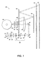
- FIG. 1 wherein there is illustrated a raster output scanning (ROS) system 10 as an embodiment of the present invention.
- the design specifications for the preferred optical system 10 require a resolution of 600 pixels per inch, (24 per mm) over a scan line of 12.2 inches (310 mm).
- a pair of laser diodes 12 and 14 emit a pair of modulated light beams 16 and 18 in the infrared wavelength range of 780 nanometers.
- the dual diodes are separated by a distance of approximately 25 ⁇ m and are oriented in the optical system so that they are offset in the cross scan direction.
- the light beams 16 and 18 pass through a flat FK5 Schott glass window 20 of the laser diodes 12 and 14.
- the dual beams 16 and 18 are next collimated by a plano-convex aspherical S-TIM35 O'Hara lens 22.
- the dual beams are then passed through an aperture or rectangular stop 24, where a portion of each beam's intensity may be attenuated.
- the aperture 24 controls the F/#, which in turn controls the spot size created by the dual beams.
- the major axis of the rectangle is in the scan plane and the minor axis of the rectangle is in the cross-scan plane.
- the collimator lens can be moved laterally in the optical path of the dual beams to allow maximum optical throughput through the aperture.
- Cylindrical lens group 26 consists of a first concave-plano S-TIM35 aspheric lens 28, a second plano-convex BK7 Schott lens 30, a third cylindrical plano-convex BK7 Schott lens 32 and a fourth cylindrical plano-convex BK7 Schott lens 34.
- the focal length and position of the cylinder lens group 26 focuses the dual beams in the cross scan plane at the overfilled facet 36 of the rotating polygon mirror 38.
- the dual beams remain collimated by the cylinder lens group 26 in the scan plane at the facet 36.
- the first aspheric lens 28 after the collimator lens 22 allows for spherical aberration correction in the tangential direction.
- the first two lenses 28 and 30 of the four lens element cylindrical lens group 26 can be moved together laterally along the optical path for optimum tangential focus correction of the dual beams.
- the third lens 32 of the four lens element cylindrical lens group 26 can be independently rotated for optimum sagittal focus correction and beam separation compensation of the dual beams.
- the fourth lens 34 of the four lens element cylindrical lens group 26 can be independently rotated for optimum sagittal focus correction and beam separation compensation of the dual beams.
- the dual beams are the reflected off the planar surface of the first folding mirror 40, and are then reflected off the planar surface of the second folding mirror 42, in the direction of the facet 36.
- the f-theta lens group consists of a first cylindrical concave-plano F2 Schott scan lens 46 and a second cylindrical plano-convex SF10 Schott scan lens 48.
- the dual beams will traverse the second f-theta scan lens 48 first from the convex side and then the first f-theta scan lens 46 from the plano side.
- the dual beams are then transmitted through a flat BK7 Schott glass window 50 to overfill the facet 36 of the rotating polygon mirror 38.
- the window 50 serves to eliminate air turbulence and contamination by foreign objects caused by the rotating polygon mirror from effecting the other optical elements of the ROS system 10.
- the dual beams 16 and 18 are reflected by the overfilled facet 36.
- the rotation of the polygon facet surface causes the dual beams to be scanned across the photoreceptor surface 52.
- the dual beams 16 and 18 then pass back through the flat window 50 and then the f-theta lens group 44 a second time, in the opposite direction, in a double pass.
- Light beams 16 and 18 are then focussed and linearized by the two element f-theta lens group 44 as the beams are transmitted, in-sequence, through the first cylindrical concave-plano F2 Schott scan lens 46 and the second cylindrical plano-convex SF10 Schott scan lens 48.
- the post-polygon f-theta lens group 44 is designed to provide a linear relationship between the rotation of the polygon mirror 38 and the deflection of the scanned beams 16 and 18 in the scan direction at the photoreceptor surface 52.
- the photoreceptor 52 moves in a process direction.
- the main function of the f-theta lens group is to control the scan linearity, in terms of uniform spot displacement per unit angle of polygon rotation.
- the dual beams 16 and 18 are reflected by a first cylindrical mirror 54, and then reflected by a second cylindrical wobble correction mirror 56, prior to passing through a flat BK7 Schott glass exit window 58.
- the exit window 58 isolates the ROS system 10 from the remainder of the xerographic engine, keeping ink, grease, dirt and other foreign objects out of the ROS optical elements.
- the dual beams 16 and 18 After passing through exit window 58, the dual beams 16 and 18 impinge upon the surface of photoreceptor 52 forming two spots.
- the two spots each produce a scan line of at least 12 inches (300 mm) (i.e., at least a page width) when scanned across the photoreceptor surface 52 by the rotating polygon mirror 38.
- the f-theta scan lens group 44 and the two cylindrical mirrors 54 and 56 focus the collimated reflected light beams 16 and 18 in the fast scan direction onto the image plane of the photoreceptor surface 52, and re-image the light focussed on the facet 36 in the cross scan direction, onto the image plane of the photoreceptor surface 52.
- the mirror 56 provides wobble correction or motion compensating optics for the dual beams.
- the two cylindrical mirrors 54 and 56 provide a telecentric condition for the dual light beams to correct for differential bow.
- the infrared laser diodes of the present invention will provide 10 erg/cm 2 energy density at the image plane of the photoreceptor. This energy density is needed for a 100 pages per minute capability at 600 dots per inch (24 dots per mm) resolution.
- the overfilled facets of the present ROS allows for a smaller polygon mirror with more facets, higher duty cycles for maximum use of diode power and lower jitter.
- the sagittal offset of the dual laser diodes coupled with a double pass ROS allows for more uniform tangential spot size at the photoreceptor.
Description
- The present invention relates to a raster scanning system and, more particularly, to a dual infrared beam, double pass raster scanning system with overfilled rotating polygon mirror facets, only cylindrical scan optical elements and independently moveable lens pairs.
- Many prior art raster output scanners (ROS) utilize a rotating polygon having flat reflective surfaces, or facets, in parallel with the axis of rotation of the polygon. In a typical system, a beam is emitted from a coherent light source such as a diode laser. The light is directed through pre-polygon conditioning optics, modulated according to an input signal, onto the rotating polygon surfaces. The high speed rotation of the polygon, typically in 3 to 15 krpm range, then scans the beam through a post-polygon conditioning lens and images the laser spot across the full process width of a photosensitive image plane.
- In these prior art ROS systems, the pre-polygon conditioning optics typically are incorporated in an underfilled facet design; e.g. the light beam directed against the rotating polygon illuminates only a portion of each rotating facet.
- In overfilled facet designs, the light beam completely illuminates each facet and a small portion of adjacent facets. In an overfilled design the requirement for facet size required to produce a given spot size at the image medium is greatly reduced allowing many more facets to be accommodated on the same diameter polygon. This, in turn, permits the scan system to form more scan lines per second with a given polygon motor, or, alternatively, to permit the use of less powerful and less expensive polygon motor drives. The overfilled design has several disadvantages. The throughput efficiency is relatively low (20%), compared to the 50% efficiency of the underfilled design, and the illumination of the imaging facet is not as uniform as the underfilled design. In order to tolerate the low efficiency, a higher powered laser diode is required.
- It is well known in the scanning art to use laser diodes to generate a coherent laser beam which is optically shaped and used to scan in a ROS system. It is also known to use multiple laser diodes to create multiple beams, each individual beam independently modulated by video signals, and the multiple beams scanned onto the recording surface as modulated beams. For these multiple beam applications, it has been found advantageous to use arrays of closely spaced laser diodes. Closely spaced diodes allow for multiple beam processing and thus improve data throughput as compared with systems that employ continuous wave, single beam gas or laser diodes. Typically, the laser diodes in a multiple beam system are individually addressable with a separate current source that drives or modulates the diode.
- EP-A-0713323 discloses a dual beam raster output scanner comprising a source of two light beams; a scanning polygon mirror; pre-scanning optics including a collimator, an aperture and a cross-scan cylinder lens; and post-scanning optics including a dual element f-theta scan lens and a wobble correcting element.
- US-A-5469290 discloses a dual beam raster output scanner comprising a scanning polygon mirror and a pre-scanning zoom system which comprises two axially adjustable lenses.
- It is an object of the present invention to provide a dual infrared beam, double pass raster scanning system with overfilled rotating polygon mirror facets and only cylindrical scan optical elements
- According to the present invention, a raster output scanner (ROS) imaging system comprises:
- a light source of a pair of laser diodes offset in the cross-scan plane for generating two coherent light beams in the infrared wavelength range, said two beams being output along an optical path,
- a photosensitive image plane;
- a rotatable multifaceted polygon mirror interposed in the optical path between said light source and said photosensitive image plane, for scanning said light beams directed onto the facets of said polygon mirror in a fast scan direction across the photosensitive image plane, said light beams directed against the rotating polygon mirror illuminating each facet in an overfilled manner;
- a post polygon mirror optical system to focus said light beams reflected from said polygon mirror in said fast scan and cross scan directions onto said photosensitive image plane, said post polygon mirror optical system including an f-theta lens group having two cylindrical lenses positioned between said polygon mirror and said photosensitive image plane to control the scan linearity of said light beams on said photosensitive image plane, a first cylindrical mirror, a second cylindrical mirror for wobble correction of said light beams along said scanning of lines on said photosensitive image plane, positioned between said f-theta lens group and said photosensitive image plane, an exit window positioned in the optical path between said second cylindrical mirror and said photosensitive image plane for preventing the contamination of said raster output scanner imaging system; and,
- a pre-polygon mirror optical system including an aspherical collimator lens positioned in the optical path between said light source and said polygon mirror, an aperture positioned in the optical path between said collimator lens and said polygon mirror, said collimating lens being moveable to maximize optical throughput of said light beams through said aperture, and a cylindrical lens group having four lenses positioned in the optical path between said aperture and said polygon mirror, said cylindrical lens group having power only in the cross scan direction, said collimator lens and said cylindrical lens group focussing said light beams in the cross scan direction at each facet of said polygon mirror while maintaining the collimation of the beam in the scan direction at each facet of said polygon mirror, wherein the first lens and the second lens of said cylindrical lens group are moveable together in said optical path for tangential focus correction of said two light beams, the third lens of said cylindrical lens group is rotatable for sagittal focus correction of said two light beams and beam separation compensation of said two light beams and the fourth lens of said cylindrical lens group is rotatable for sagittal focus correction of said two light beams and beam separation compensation of said two light beams, two folding mirrors positioned in the optical path between said cylindrical lens group and said polygon mirror, and a scanning window positioned in the optical path between said folding mirrors and said polygon mirror for preventing contamination and turbulence from said polygon mirror, wherein said light beams pass through said f-theta lens group positioned in the optical path between said two folding mirrors and said scanning window.
-
- A particular embodiment in accordance with this invention will now be described with reference to the accompanying drawings which is a schematic perspective view of the dual infrared beam, double pass raster scanning system.
- Reference is now made to Figure 1, wherein there is illustrated a raster output scanning (ROS)
system 10 as an embodiment of the present invention. The design specifications for the preferredoptical system 10 require a resolution of 600 pixels per inch, (24 per mm) over a scan line of 12.2 inches (310 mm). - A pair of
laser diodes light beams - The
light beams glass window 20 of thelaser diodes dual beams O'Hara lens 22. - Once transmitted through the aspherical
collimating lens 22, the dual beams are then passed through an aperture orrectangular stop 24, where a portion of each beam's intensity may be attenuated. Theaperture 24 controls the F/#, which in turn controls the spot size created by the dual beams. The major axis of the rectangle is in the scan plane and the minor axis of the rectangle is in the cross-scan plane. The collimator lens can be moved laterally in the optical path of the dual beams to allow maximum optical throughput through the aperture. -
Light beams cylindrical lens group 26.Cylindrical lens group 26 consists of a first concave-plano S-TIM35aspheric lens 28, a second plano-convex BK7 Schottlens 30, a third cylindrical plano-convex BK7 Schottlens 32 and a fourth cylindrical plano-convex BK7 Schott lens 34. - The focal length and position of the
cylinder lens group 26 focuses the dual beams in the cross scan plane at the overfilledfacet 36 of the rotatingpolygon mirror 38. The dual beams remain collimated by thecylinder lens group 26 in the scan plane at thefacet 36. - The first
aspheric lens 28 after thecollimator lens 22 allows for spherical aberration correction in the tangential direction. - The first two
lenses cylindrical lens group 26 can be moved together laterally along the optical path for optimum tangential focus correction of the dual beams. Thethird lens 32 of the four lens elementcylindrical lens group 26 can be independently rotated for optimum sagittal focus correction and beam separation compensation of the dual beams. The fourth lens 34 of the four lens elementcylindrical lens group 26 can be independently rotated for optimum sagittal focus correction and beam separation compensation of the dual beams. - Having been focussed in the cross scan plane by
cylinder lens group 26, the dual beams are the reflected off the planar surface of thefirst folding mirror 40, and are then reflected off the planar surface of thesecond folding mirror 42, in the direction of thefacet 36. - After the two reflections, the dual beams are transmitted through the two element f-
theta lens group 44. The f-theta lens group consists of a first cylindrical concave-plano F2 Schottscan lens 46 and a second cylindrical plano-convex SF10 Schottscan lens 48. After reflection from thesecond fold mirror 42, the dual beams will traverse the second f-theta scan lens 48 first from the convex side and then the first f-theta scan lens 46 from the plano side. - The dual beams are then transmitted through a flat BK7 Schott
glass window 50 to overfill thefacet 36 of the rotatingpolygon mirror 38. Thewindow 50 serves to eliminate air turbulence and contamination by foreign objects caused by the rotating polygon mirror from effecting the other optical elements of theROS system 10. - The
dual beams overfilled facet 36. The rotation of the polygon facet surface causes the dual beams to be scanned across thephotoreceptor surface 52. - The
dual beams flat window 50 and then the f-theta lens group 44 a second time, in the opposite direction, in a double pass. -
Light beams theta lens group 44 as the beams are transmitted, in-sequence, through the first cylindrical concave-plano F2 Schottscan lens 46 and the second cylindrical plano-convex SF10 Schottscan lens 48. - The post-polygon f-
theta lens group 44 is designed to provide a linear relationship between the rotation of thepolygon mirror 38 and the deflection of the scannedbeams photoreceptor surface 52. Thephotoreceptor 52 moves in a process direction. The main function of the f-theta lens group is to control the scan linearity, in terms of uniform spot displacement per unit angle of polygon rotation. - After the f-
theta lens group 44, thedual beams cylindrical mirror 54, and then reflected by a second cylindricalwobble correction mirror 56, prior to passing through a flat BK7 Schottglass exit window 58. Theexit window 58 isolates theROS system 10 from the remainder of the xerographic engine, keeping ink, grease, dirt and other foreign objects out of the ROS optical elements. - After passing through
exit window 58, thedual beams photoreceptor 52 forming two spots. The two spots each produce a scan line of at least 12 inches (300 mm) (i.e., at least a page width) when scanned across thephotoreceptor surface 52 by the rotatingpolygon mirror 38. - The f-theta
scan lens group 44 and the twocylindrical mirrors light beams photoreceptor surface 52, and re-image the light focussed on thefacet 36 in the cross scan direction, onto the image plane of thephotoreceptor surface 52. - The
mirror 56 provides wobble correction or motion compensating optics for the dual beams. The twocylindrical mirrors - The infrared laser diodes of the present invention will provide 10 erg/cm2 energy density at the image plane of the photoreceptor. This energy density is needed for a 100 pages per minute capability at 600 dots per inch (24 dots per mm) resolution.
- The overfilled facets of the present ROS allows for a smaller polygon mirror with more facets, higher duty cycles for maximum use of diode power and lower jitter.
- The sagittal offset of the dual laser diodes coupled with a double pass ROS allows for more uniform tangential spot size at the photoreceptor.
Claims (1)
- A raster output scanner (ROS) imaging system comprising:a light source of a pair of laser diodes (12, 14) offset in the cross-scan plane for generating two coherent light beams in the infrared wavelength range, said two beams being output along an optical path,a photosensitive image plane (52);a rotatable multifaceted polygon mirror (38) interposed in the optical path between said light source (12, 14) and said photosensitive image plane (52), for scanning said light beams directed onto the facets (36) of said polygon mirror (38) in a fast scan direction across the photosensitive image plane (52), said light beams directed against the rotating polygon mirror (38) illuminating each facet (36) in an overfilled manner;a post polygon mirror optical system to focus said light beams reflected from said polygon mirror (38) in said fast scan and cross scan directions onto said photosensitive image plane (52), said post polygon mirror optical system including an f-theta lens group (44) having two cylindrical lenses (46, 48) positioned between said polygon mirror (38) and said photosensitive image plane (52) to control the scan linearity of said light beams on said photosensitive image plane (52), a first cylindrical mirror (54), a second cylindrical mirror (56) for wobble correction of said light beams along said scanning of lines on said photosensitive image plane positioned between said f-theta lens group (44) and said photosensitive image plane (52), an exit window (58) positioned in the optical path between said second cylindrical mirror (56) and said photosensitive image plane (52) for preventing the contamination of said raster output scanner imaging system; and,a pre-polygon mirror optical system including an aspherical collimator lens (22) positioned in the optical path between said light source (12, 14) and said polygon mirror (38), an aperture (24) positioned in the optical path between said collimator lens (22) and said polygon mirror (38), said collimating lens (22) being moveable to maximize optical throughput of said light beams through said aperture (24), and a cylindrical lens group (26) having four lenses positioned in the optical path between said aperture (24) and said polygon mirror (38), said cylindrical lens group (26) having power only in the cross scan direction, said collimator lens (22) and said cylindrical lens group (26) focussing said light beams in the cross scan direction at each facet (36) of said polygon mirror (38) while maintaining the collimation of the beam in the scan direction at each facet (36) of said polygon mirror (38), wherein the first lens (28) and the second lens (30) of said cylindrical lens group (26) are moveable together in said optical path for tangential focus correction of said two light beams, the third lens (32) of said cylindrical lens group (26) is rotatable for sagittal focus correction of said two light beams and beam separation compensation of said two light beams and the fourth lens (34) of said cylindrical lens group (26) is rotatable for sagittal focus correction of said two light beams and beam separation compensation of said two light beams, two folding mirrors (40, 42) positioned in the optical path between said cylindrical lens group (26) and said polygon mirror (38), and a scanning window (50) positioned in the optical path between said folding mirrors (40, 42) and said polygon mirror for preventing contamination and turbulence from said polygon mirror (38), wherein said light beams pass through said f-theta lens group (44) positioned in the optical path between said two folding mirrors (40, 42) and said scanning window (50).
Applications Claiming Priority (2)
| Application Number | Priority Date | Filing Date | Title |
|---|---|---|---|
| US09/218,853 US6057953A (en) | 1998-12-21 | 1998-12-21 | Dual beam double pass raster output scanner |
| US218853 | 1998-12-21 |
Publications (2)
| Publication Number | Publication Date |
|---|---|
| EP1014149A1 EP1014149A1 (en) | 2000-06-28 |
| EP1014149B1 true EP1014149B1 (en) | 2002-08-07 |
Family
ID=22816760
Family Applications (1)
| Application Number | Title | Priority Date | Filing Date |
|---|---|---|---|
| EP99309973A Expired - Lifetime EP1014149B1 (en) | 1998-12-21 | 1999-12-10 | Raster output scanner |
Country Status (4)
| Country | Link |
|---|---|
| US (1) | US6057953A (en) |
| EP (1) | EP1014149B1 (en) |
| JP (1) | JP2000180761A (en) |
| DE (1) | DE69902433T2 (en) |
Families Citing this family (29)
| Publication number | Priority date | Publication date | Assignee | Title |
|---|---|---|---|---|
| US6369927B2 (en) * | 1998-02-13 | 2002-04-09 | Ricoh Company, Ltd. | Optical scanning apparatus |
| JP3397765B2 (en) * | 1999-12-10 | 2003-04-21 | キヤノン株式会社 | Multi-beam optical scanning optical system and image forming apparatus using the same |
| JP2002040349A (en) * | 2000-07-26 | 2002-02-06 | Sharp Corp | Optical scanner |
| US6967908B2 (en) * | 2000-09-07 | 2005-11-22 | Pioneer Corporation | Optical pickup device with focus error detecting optical element and method for focus error detection |
| JP3902933B2 (en) * | 2001-09-27 | 2007-04-11 | キヤノン株式会社 | Multi-beam optical scanning optical system and image forming apparatus using the same |
| JP2003172874A (en) * | 2001-12-05 | 2003-06-20 | Samsung Electro Mech Co Ltd | Light irradiation device, optical pickup device provided with the same and method of adjusting light irradiation device |
| JP3607255B2 (en) * | 2002-03-25 | 2005-01-05 | 株式会社リコー | Optical scanning apparatus and image forming apparatus |
| US7733310B2 (en) * | 2005-04-01 | 2010-06-08 | Prysm, Inc. | Display screens having optical fluorescent materials |
| US7474286B2 (en) * | 2005-04-01 | 2009-01-06 | Spudnik, Inc. | Laser displays using UV-excitable phosphors emitting visible colored light |
| US7791561B2 (en) * | 2005-04-01 | 2010-09-07 | Prysm, Inc. | Display systems having screens with optical fluorescent materials |
| US7994702B2 (en) * | 2005-04-27 | 2011-08-09 | Prysm, Inc. | Scanning beams displays based on light-emitting screens having phosphors |
| US8000005B2 (en) | 2006-03-31 | 2011-08-16 | Prysm, Inc. | Multilayered fluorescent screens for scanning beam display systems |
| US8089425B2 (en) * | 2006-03-03 | 2012-01-03 | Prysm, Inc. | Optical designs for scanning beam display systems using fluorescent screens |
| US7466331B2 (en) * | 2005-12-07 | 2008-12-16 | Palo Alto Research Center Incorporated | Bow-free telecentric optical system for multiple beam scanning systems |
| CN101000306B (en) * | 2006-01-09 | 2010-11-17 | 深圳迈瑞生物医疗电子股份有限公司 | Cell analyser |
| US8451195B2 (en) * | 2006-02-15 | 2013-05-28 | Prysm, Inc. | Servo-assisted scanning beam display systems using fluorescent screens |
| US7884816B2 (en) * | 2006-02-15 | 2011-02-08 | Prysm, Inc. | Correcting pyramidal error of polygon scanner in scanning beam display systems |
| US20080068295A1 (en) * | 2006-09-19 | 2008-03-20 | Hajjar Roger A | Compensation for Spatial Variation in Displayed Image in Scanning Beam Display Systems Using Light-Emitting Screens |
| US8013506B2 (en) * | 2006-12-12 | 2011-09-06 | Prysm, Inc. | Organic compounds for adjusting phosphor chromaticity |
| GB2460802B (en) * | 2007-03-20 | 2012-09-05 | Prysm Inc | Delivering and displaying advertisment or other application data to display systems |
| US7697183B2 (en) * | 2007-04-06 | 2010-04-13 | Prysm, Inc. | Post-objective scanning beam systems |
| US8169454B1 (en) | 2007-04-06 | 2012-05-01 | Prysm, Inc. | Patterning a surface using pre-objective and post-objective raster scanning systems |
| CN101950122B (en) | 2007-05-17 | 2012-01-04 | Prysm公司 | Multilayered screens with light-emitting stripes for scanning beam display systems |
| US7878657B2 (en) * | 2007-06-27 | 2011-02-01 | Prysm, Inc. | Servo feedback control based on invisible scanning servo beam in scanning beam display systems with light-emitting screens |
| US8556430B2 (en) | 2007-06-27 | 2013-10-15 | Prysm, Inc. | Servo feedback control based on designated scanning servo beam in scanning beam display systems with light-emitting screens |
| US8217975B2 (en) * | 2008-04-01 | 2012-07-10 | Xerox Corporation | Apparatus for forming an image and corresponding methods |
| US7869112B2 (en) * | 2008-07-25 | 2011-01-11 | Prysm, Inc. | Beam scanning based on two-dimensional polygon scanner for display and other applications |
| JP5079060B2 (en) * | 2010-08-02 | 2012-11-21 | シャープ株式会社 | Optical scanning apparatus and image forming apparatus |
| KR20170040911A (en) * | 2015-10-06 | 2017-04-14 | 삼성전자주식회사 | Multi-beam scanner and confocal optical system |
Family Cites Families (7)
| Publication number | Priority date | Publication date | Assignee | Title |
|---|---|---|---|---|
| JP2563260B2 (en) * | 1986-04-11 | 1996-12-11 | 松下電器産業株式会社 | Optical beam scanning device |
| JPH07199109A (en) * | 1993-10-14 | 1995-08-04 | Xerox Corp | Raster scanning system |
| US5512949A (en) * | 1993-12-29 | 1996-04-30 | Xerox Corporation | Multiple beam raster output scanner optical system having telecentric chief exit rays |
| US5469290A (en) * | 1994-06-06 | 1995-11-21 | Xerox Corporation | Two-element zoom lens for beam separation error correction |
| US5550668A (en) * | 1994-11-21 | 1996-08-27 | Xerox Corporation | Multispot polygon ROS with maximized line separation depth of focus |
| JP3545115B2 (en) * | 1995-09-22 | 2004-07-21 | 大日本スクリーン製造株式会社 | Method of correcting curvature of field and light beam scanning device used in the method |
| JP3104618B2 (en) * | 1996-05-10 | 2000-10-30 | 富士ゼロックス株式会社 | Optical scanning device and optical lens |
-
1998
- 1998-12-21 US US09/218,853 patent/US6057953A/en not_active Expired - Fee Related
-
1999
- 1999-12-10 DE DE69902433T patent/DE69902433T2/en not_active Expired - Fee Related
- 1999-12-10 EP EP99309973A patent/EP1014149B1/en not_active Expired - Lifetime
- 1999-12-17 JP JP11358347A patent/JP2000180761A/en not_active Withdrawn
Also Published As
| Publication number | Publication date |
|---|---|
| JP2000180761A (en) | 2000-06-30 |
| EP1014149A1 (en) | 2000-06-28 |
| DE69902433D1 (en) | 2002-09-12 |
| US6057953A (en) | 2000-05-02 |
| DE69902433T2 (en) | 2002-12-12 |
Similar Documents
| Publication | Publication Date | Title |
|---|---|---|
| EP1014149B1 (en) | Raster output scanner | |
| EP1111435B1 (en) | Multiple wobble correction optical elements to reduce height of raster output (ros) system | |
| US6459520B1 (en) | Optical scanning apparatus and image forming apparatus using it | |
| US5526166A (en) | Optical system for the correction of differential scanline bow | |
| US5550668A (en) | Multispot polygon ROS with maximized line separation depth of focus | |
| US7486426B2 (en) | Two-dimensional optical scan system using a counter-rotating disk scanner | |
| EP1014148B1 (en) | Raster output scanner with overfilled polygonal mirror and cylindrical optical elements | |
| EP0454503B1 (en) | Optical scanners | |
| US5247383A (en) | Scanner with a post facet lens system | |
| US6061080A (en) | Aperture for multiple reflection raster output scanning system to reduce bow | |
| EP0637770B1 (en) | Compact ROS imaging system | |
| EP0857991B1 (en) | Scanning optical system | |
| US5142403A (en) | ROS scanner incorporating cylindrical mirror in pre-polygon optics | |
| US5650871A (en) | Single element optics for passive facet tracking | |
| KR20050110687A (en) | Post-objective scanning device | |
| US5381259A (en) | Raster output scanner (ROS) using an overfilled polygon design with minimized optical path length | |
| JP4632751B2 (en) | Optical scanning device | |
| EP0806691A2 (en) | Achromatic, telecentric f-theta scan lens optical system | |
| JPH01200220A (en) | Light beam scanning optical system | |
| KR100193596B1 (en) | Anamorphic Lenses for Scanning Optical Devices | |
| JP2983666B2 (en) | Multiple wavelength, multiple diode laser ROS | |
| JPH08220457A (en) | Optical scanner | |
| US20040080801A1 (en) | Multi-beam light scanning apparatus | |
| JP2000147408A (en) | Optical scanner | |
| WO2005076053A9 (en) | Scanner systems |
Legal Events
| Date | Code | Title | Description |
|---|---|---|---|
| PUAI | Public reference made under article 153(3) epc to a published international application that has entered the european phase |
Free format text: ORIGINAL CODE: 0009012 |
|
| AK | Designated contracting states |
Kind code of ref document: A1 Designated state(s): DE FR GB |
|
| AX | Request for extension of the european patent |
Free format text: AL;LT;LV;MK;RO;SI |
|
| 17P | Request for examination filed |
Effective date: 20001228 |
|
| AKX | Designation fees paid |
Free format text: DE FR GB |
|
| 17Q | First examination report despatched |
Effective date: 20010227 |
|
| GRAG | Despatch of communication of intention to grant |
Free format text: ORIGINAL CODE: EPIDOS AGRA |
|
| GRAG | Despatch of communication of intention to grant |
Free format text: ORIGINAL CODE: EPIDOS AGRA |
|
| GRAH | Despatch of communication of intention to grant a patent |
Free format text: ORIGINAL CODE: EPIDOS IGRA |
|
| GRAH | Despatch of communication of intention to grant a patent |
Free format text: ORIGINAL CODE: EPIDOS IGRA |
|
| GRAA | (expected) grant |
Free format text: ORIGINAL CODE: 0009210 |
|
| AK | Designated contracting states |
Kind code of ref document: B1 Designated state(s): DE FR GB |
|
| REG | Reference to a national code |
Ref country code: GB Ref legal event code: FG4D |
|
| REF | Corresponds to: |
Ref document number: 69902433 Country of ref document: DE Date of ref document: 20020912 |
|
| ET | Fr: translation filed | ||
| PLBE | No opposition filed within time limit |
Free format text: ORIGINAL CODE: 0009261 |
|
| STAA | Information on the status of an ep patent application or granted ep patent |
Free format text: STATUS: NO OPPOSITION FILED WITHIN TIME LIMIT |
|
| 26N | No opposition filed |
Effective date: 20030508 |
|
| PGFP | Annual fee paid to national office [announced via postgrant information from national office to epo] |
Ref country code: GB Payment date: 20061206 Year of fee payment: 8 |
|
| PGFP | Annual fee paid to national office [announced via postgrant information from national office to epo] |
Ref country code: DE Payment date: 20061207 Year of fee payment: 8 |
|
| PGFP | Annual fee paid to national office [announced via postgrant information from national office to epo] |
Ref country code: FR Payment date: 20061208 Year of fee payment: 8 |
|
| GBPC | Gb: european patent ceased through non-payment of renewal fee |
Effective date: 20071210 |
|
| PG25 | Lapsed in a contracting state [announced via postgrant information from national office to epo] |
Ref country code: DE Free format text: LAPSE BECAUSE OF NON-PAYMENT OF DUE FEES Effective date: 20080701 |
|
| REG | Reference to a national code |
Ref country code: FR Ref legal event code: ST Effective date: 20081020 |
|
| PG25 | Lapsed in a contracting state [announced via postgrant information from national office to epo] |
Ref country code: GB Free format text: LAPSE BECAUSE OF NON-PAYMENT OF DUE FEES Effective date: 20071210 |
|
| PG25 | Lapsed in a contracting state [announced via postgrant information from national office to epo] |
Ref country code: FR Free format text: LAPSE BECAUSE OF NON-PAYMENT OF DUE FEES Effective date: 20071231 |