EP1013449A2 - Ink bag for ink jet type recording apparatus and package suitable for packing such ink bag - Google Patents
Ink bag for ink jet type recording apparatus and package suitable for packing such ink bag Download PDFInfo
- Publication number
- EP1013449A2 EP1013449A2 EP99125921A EP99125921A EP1013449A2 EP 1013449 A2 EP1013449 A2 EP 1013449A2 EP 99125921 A EP99125921 A EP 99125921A EP 99125921 A EP99125921 A EP 99125921A EP 1013449 A2 EP1013449 A2 EP 1013449A2
- Authority
- EP
- European Patent Office
- Prior art keywords
- ink bag
- films
- ink
- sides
- film
- Prior art date
- Legal status (The legal status is an assumption and is not a legal conclusion. Google has not performed a legal analysis and makes no representation as to the accuracy of the status listed.)
- Granted
Links
Images


Classifications
-
- B—PERFORMING OPERATIONS; TRANSPORTING
- B41—PRINTING; LINING MACHINES; TYPEWRITERS; STAMPS
- B41J—TYPEWRITERS; SELECTIVE PRINTING MECHANISMS, i.e. MECHANISMS PRINTING OTHERWISE THAN FROM A FORME; CORRECTION OF TYPOGRAPHICAL ERRORS
- B41J2/00—Typewriters or selective printing mechanisms characterised by the printing or marking process for which they are designed
- B41J2/005—Typewriters or selective printing mechanisms characterised by the printing or marking process for which they are designed characterised by bringing liquid or particles selectively into contact with a printing material
- B41J2/01—Ink jet
- B41J2/17—Ink jet characterised by ink handling
- B41J2/175—Ink supply systems ; Circuit parts therefor
- B41J2/17503—Ink cartridges
- B41J2/17513—Inner structure
Definitions
- the present invention relates to an ink container which is removably accommodated in a casing of an ink jet type recording apparatus to supply ink to a recording head and, in more particular, to a flexible ink bag for storing ink therein.
- An ink jet type recording apparatus performs a printing operation by reciprocating a recording head in the sheet width direction of a recording sheet.
- a recording apparatus which carries out a large amount of print, generally adopts an arrangement in which the ink supply source is disposed in a casing of the apparatus whereas ink is supplied through a tube to the recording head.
- the ink jet type recording apparatus is designed to pressurize ink in a pressure generation chamber to thereby generate ink droplets. If the ink contains air bubbles therein, then the pressure generated is reduced due to such air bubbles to lower the ejection performance of the ink droplets. In order to avoid this problem, the ink jet type recording apparatus requires ink which eliminates dissolved air therefrom.
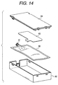
- an ink bag 60 shown in Fig. 14 is formed in the following manner: That is, a laminated film having a gas barrier property, which is composed of a polyethylene film and aluminum vapor-deposited on the polyethylene film, is folded at its center so that two half sections of the laminated film are superimposed one on the other. The three sides of the thus superimposed laminated film except for one short side thereof are connected together by thermal fusion or any other suitable processing. The remaining one short side is sealed with an ink supply hole forming member 61 made of a plastic molding be secured thereto. Further, in order to protect the ink bag 60 from damage due to an external force or the like and to form an ink cartridge, the ink bag 60 is stored in a hard case 62 formed of high-molecular material.
- reference numeral 63 designates a plate member to be fixed to one side of the ink bag 60 to deform the ink bag 60 uniformly and enable detection of the ink end
- 64 designates a cover forming a part of the hard case 62.
- the ink bag for commercial printing purpose must be supplied or distributed to a user without being stored in the hard case because the capacity of the ink bag 60 must be increased as well as the cost thereof must be reduced.
- the ink bag itself is required to have such strength as to withstand the distribution and a setting operation for setting the ink bag into a recording apparatus, but the increased strength of the ink bag hinders smooth reduction of the capacity of the bag in conjunction with the ink consumption by printing, which, in turn, incurs an obstacle to the supply of ink to the recording head.
- the ink bag which is filled with ink, has such a rounded shape that the central portion of the ink bag is larger in thickness than the peripheral portions thereof, and therefore the accommodation of the relatively rounded ink bag into an easy-to-handle rectangular case arises another problem in that space utility is low due to the presence of a dead space.
- the ink storage capacity of the ink bag is increased, then the shaking or rocking motion of the ink during the distribution causes greater shocks to the ink bag, so that the ink bag is easy to break.
- a second object of the present invention is to provide an ink bag which can maintain its rectangular shape by itself in its ink filled state to thereby provide a high ink filling efficiency.
- a third object of the present invention is to provide an ink bag which can supply ink to the recording apparatus positively.
- a fourth object of the invention is to provide an ink bag which provides a rectangular shape in its ink filled state to thereby allow it to be stored in a recording apparatus with only a small dead space produced.
- a fifth object of the invention is to provide an ink bag, which is able to receive external forces acting on the four corners of the ink bag in such a manner that the external forces are dispersed by four connecting portions formed in their associated four corners of the ink bag to thereby able to prevent the ink bag against damage as much as possible.
- a sixth object of the invention is to provide an ink bag, which, according to the ink amount, can reduce the thickness of the side surface portions of the ink bag having relatively weak rigidity due to tensile forces given from connecting portions of the four corners of the ink bag to thereby be able to discharge ink positively.
- a seventh object of the invention to provide a package for packing therein an ink bag in such a manner that the side surface portions of the ink bag are supported and held by and between the side surface inner packing members of the package, and the shoulder portions of the ink bag are supported and held by and between the end portion inner packing members of the package to eliminate a space for oscillation of the ink bag, thereby being able to prevent the ink bag from being damaged by large shocks that could be possibly applied to the ink bag during distribution.
- An ink bag is structured such that, to the respective long side portions of a rectangular-shaped, thermally fusible first film forming the surface portions of the ink bag, there are attached, by thermal fusion, the long side portions of a rectangular-shaped, thermally fusible second film forming the side surface portions of the ink bag and having lower rigidity than the first film to thereby form a cylindrical body.
- the one-side short side portions of the surface portions of the ink bag are attached together by thermal fusion to thereby form a bag body.
- An ink supply hole forming member is attached by thermal fusion to the other-side short side portions of the surface portions of the ink bag.
- strip-like connecting portions each starting from one of the two mutually adjoining sides of the ink bag and reaching the other of the two sides.
- An ink bag package includes end portion inner packing members, each having a trapezoidal-shaped section, for holding between them the end portion areas of the short-side sides of the ink bag from both surfaces thereof.
- the package further includes rectangular-shaped side surface inner packing members to be respectively contacted with the side surfaces of the long-side sides of the ink bag.
- a container is provided for storing therein theses inner packing members together with the ink bag.
- Figs. 1 (a), (b) and Figs. 2 (a), (b) show an ink bag 19 according to an embodiment of the invention.
- the ink bag 19 has first rectangular films 1 and 2 as top and bottom surfaces, second rectangular films 3 and 4 as side surfaces, and an ink supply hole forming member 5.
- the second rectangular films 3 and 4 are lower in rigidity than the first rectangular films 1 and 2.
- each of the second rectangular films 3 and 4 may be folded, for instance, along a center line C, may be formed by selecting different material than the first rectangular films 1 and 2, etc.
- the ink bag 19 is formed, preferably, by the following procedure:
- the first films 1 and 2 are aligned together in a state that the second film 3 and 4 each folded along the center line C are interposed therebetweeen.
- the long side portions 1a, 1b, 2a, and 2b of the first films 1 and 2 are respectively attached to the long side portions 3a, 4a, 3b and 4b of the second films 3 and 4, for instance, by thermal fusion, to thereby form a hollow assembly.
- One end of the hollow assembly is closed, whereas the ink supply hole forming member 5 is attached to the other end of the hollow assembly.
- the central portions of the short side portions 1c and 2c of the first films 1 and 2 are attached by thermal fusion to each other, and the remaining portions of the short side portions 1c and 2c of the first films 1 and 2 are attached by thermal fusion to the short side portions of the second films 3 and 4.
- the central portion of the short side portion 1d of the first film 1 is attached by thermal fusion to either of the central portion of the short side portion 2d of the first film 2 and the outer periphery of the ink supply hole forming member 5, the central portion of the short side portion 2d of the first film 2 is attached by thermal fusion to either of the central portion of the short side portion 1d of the first film 1, and the remaining portions of the short side portions 1d and 2d of the first films 1 and 2 are attached by thermal fusion to the short side portions of the second films 3 and 4.
- the half of the second film 3 (4) with respect to the central line C, which extends along the short side 1c, may be attached to the other half of the second film 3 (4) or may be separated therefrom.
- the ink bag 19 of this embodiment is further formed with connecting portions 6 to 9 at its four corners.
- Each of the connecting portions 6 to 9 is formed, by thermal fusion, as a strip extending obliquely from one side of the ink bag 19 to another adjacent side of the ink bag 19 and across the folding line D (i.e. the central line C) as best shown in Fig. 2.
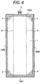
- the connecting portions 6 to 9 may be formed not to extend across the folding lines D'.
- the former case in which the folding lines D of the second films 3 and 4 are situated on the connecting portions 6 to 9 as shown in Fig. 2 is advantageous, from the viewpoint of reinforcement, over the latter case in which the folding lines D' of the second films 3 and 4 are situated inwardly of the connecting portions 6 to 9 as shown in Fig. 6, since the connecting portions 6-9 of the former case can more positively reinforce the areas E of the ink bag 19, where the first films 1 and 2 and the second film 3 or 4 are overlapped together in a complicated manner.
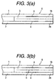
- each of the connecting portions 6 to 9 is formed such that the first films 1 and 2 are attached to the second film 3 or 4 at thermally fused areas a. That is, the thermally fused areas a is located between mutually contacting surfaces of the first film 1 (2) and the second film 3 (or 4) within the interior of the ink bag 19.
- the connecting portion 6 (to 9) of this arrangement can provide sufficient strength to the ink bag 19, but if larger strength is required, then it is preferable to further attach the half of the second film 3 (4) to the other half of the second film 3 (4) as illustrated by a thermally fused area b in Fig. 3(b). That is, in Fig. 3(b), the mutually contacting surfaces of the halves of the second film 3 (4), which are located outside the ink bag 19, are attached to each other at the thermally fused area b.
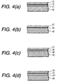
- Each of the first films 1 and 2 preferably has such a laminated structure as shown in Fig. 4(a), which includes a polyethylene layer 10 of about 100 ⁇ m thickness, a polyester layer 11 of about 25 ⁇ m thickness, a gas-impermeable and flexible metal layer, such as an aluminum layer 12, of about 15 ⁇ m thickness, and, a protective layer, such as a polyester layer 13, of about 38 ⁇ m thickness.
- a laminated structure as shown in Fig. 4(a)
- a polyethylene layer 10 of about 100 ⁇ m thickness
- a polyester layer 11 of about 25 ⁇ m thickness
- a gas-impermeable and flexible metal layer such as an aluminum layer 12, of about 15 ⁇ m thickness
- a protective layer such as a polyester layer 13, of about 38 ⁇ m thickness.
- a polyester layer 13 of about 38 ⁇ m thickness.
- the second film 3, 4 may further has another nylon layer 18 interposed between the polyethylene layer 15 and aluminum layer 16.
- the above-exemplified laminated structure for the films 1, 2, 3 and 4 are advantageously useful to readily provide the ink bag 19 having sufficient connection strength and sufficient airtightness using the thermal fusion.
- the polyethylene layer 10 of the each of the first film 1 and 2 is attached by thermal fusion to the peripheries of the polyethylene layers 15 of the second films 3 and 4 in a state that each of the second films 3 and 4 has been folded at the central line C and aligned to the first films 1 and 2. It is generally known that the polyethylene is lower in fusing or melting point than the nylon.
- the heat to be applied to the first and second films 1 and 3 for thermal fusion is selected to cause thermal fusion on of the mutually contacting polyethylene surfaces but not cause on the mutually contacting nylon surfaces. If it is required, as shown in Fig.
- the heat to be applied to the first and second films 1 and 3 for thermal fusion is selected to cause thermal fusion on both of the mutually contacting polyethylene surfaces and the mutually contacting nylon surfaces.
- an adhesive may be applied to the mutually contacting nylon surfaces, or a suitable material for the second film 3 may be selected in place of the nylon layer 17.
- the ink supply hole is sealed by a septum.
- the ink bag 19 filled completely with ink is inflated or expanded into a relatively flat and substantially parallelepiped shape as shown in Fig. 5 (I) while the connecting portions 6 - 9 at four corners and the short side portions 1c, 1d, 2c, 2d, etc. of the ink bag 19 prevent unnecessary expansion of the ink bag 19. In this state, even if the ink bag is given an excessive force due to its fall or the like, the four corners of the ink bag 19 is protected by the relatively wide connecting portions 6 to 9 which serve to disperse the applied excessive force. Therefore, the ink bag 19 is free from the damage.
- the ink remains unchanged chemically. Further, since the aluminum layers 12 and 16 isolate the ink inside the ink bag from ambient air, the degassed condition of the ink can be maintained for a long period of time. That is, the quality of the ink applied when it is shipped from a factory can be maintained for a long time.
- the ink in the ink bag is supplied through an ink supply tube to a recording head.
- the relatively weak side surface portions i.e. the films 3 and 4 are deformed in conjunction with the consumed amount of the ink to reduce the thickness of the ink bag 19.
- each of the films 3 and 4 has such a tendency as to be deformed along the central line C and the connecting portions 6 to 9 effectively serve to transmit tensile forces from the first films 1 and 2 to the second films 3 and 4 to move the center lines C of the second films 3 and 4 inwardly, the thickness reduction of the ink bag 19 in conjunction with the ink consumed amount is facilitated (Fig. 5 (II)).
- the side surface portions, i.e. the second films 3 and 4 are folded completely so that the half of the second film 3 (4) is contacted with the other half of the second film 3 (4) as well as the one of the first films 1 and 2 is contacted with the other of the first films 1 and 2.
- the ink stored in the ink bag can be discharged completely and surely (Fig. 5 (III)).
- Fig. 4 (d) is another preferable example for each of the first films 1 and 2.
- a difference of the structure shown in Fig. 4 (d) from the structure shown in Fig. 4 (a) is that the intermediate polyester layer 11 in the structure shown in Fig. 4 (a) is replaced with a nylon layer 17'.
- This structure makes it possible to more positively prevent the damage and breakage of the ink bag 19 caused due to the shaking or rocking motion of the ink, the impact applied to the ink bag 19 or the like, since the nylon superior in breaking strength to polyester is incorporated as an intermediate layer to the laminated structure.
- the polyester layer 13 (and 11) serves to assist or facilitate the folding of the ink bag 19 in conjunction with the ink consumption as described with reference to Fig. 5, since the polyester possesses a certain rigidity or tension. That is, the provision of the polyester layer 13 (and 11) makes it possible to surely discharge the ink from the interior of the ink bag 19.
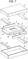
- Fig. 7 shows an example of a package which is preferably used to pack the above-mentioned ink bag 19 to improve the handling of the ink bag 19 during distribution to a user.
- the ink bag 19 shown in Fig. 7 is not formed with the connecting portions 6 to 9, but may have the connecting portions 6 to 9 similarly to the ink bag 19 shown in Fig. 1.
- the present package comprises an outer packing member, which is composed of a box-shaped container main body 20 having a depth L1 smaller than the thickness d of the ink bag 19 and a box-shaped upper cover 21, four end portion inner packing members 22, 23, 24 and 25 respectively including inclined surfaces almost identical with the inclined surfaces of their associated end portions of the ink bag 19 on the long-side side thereof and each having a trapezoidal-shaped section, and two side surface inner packing members 26 and 27 which can be respectively inserted into their associated recesses formed in the two side surfaces of the ink bag 19.
- the four end portion inner packing members 22 to 25 are structured such that, when the pair of the inner packing members 22 and 24 (or the pair of the inner packing members 23 and 25) hold the end portion (short side) 19h of the ink bag 19 therebetween to be respectively contacted with the upper and lower surfaces of the end portion 19h, a total height L2 of the pair of the end portion inner packing members 22 and 24 (or 23 and 25) is larger than the depth L1 of the container main body 20 and smaller than the maximum thickness d of the ink bag 19.
- each of the end portion inner packing members 22 to 25 is manufactured by molding high-molecular foaming material into a trapezoidal cross-sectional shape to have a perpendicular surface on one end side and an inclined surface on the opposite side, which substantially matches with a corresponding one of shoulder portions 19a to 19d of the ink bag 19.
- Each of the side surface portion inner packing members 26 and 27, in the present embodiment, is manufactured by molding high-molecular foaming material into a rectangular cross-sectional shape.
- the lateral thickness of the side surface portion inner packing member 26 (27) is set such that, when the side surface portion inner packing member 26 (27) is installed onto the second film 3 (4) of ink bag 19, the surface of the side surface portion inner packing member 26 (27) is slightly protruded laterally from the ink bag 19.
- the end portion inner packing members 22 and 23 are first placed on the two ends of the bottom portion of the container main body 20 in such a manner the inclined surfaces thereof face upwardly. Thereafter, the ink bag 19 is placed onto the thus placed end portion inner packing members 22 and 23 in a state that the side surface inner packing members 26 and 27 have been inserted to respectively abut the side surfaces (the second films) 3 and 4 of the ink bag 19. Thereafter, the end portion inner packing members 24 and 25 are placed onto the two end portions of the container main body 20 with their inclined surfaces facing downward, and an upper cover 21 is then set onto the container main body 20.
- the ink bag 19 is stored within and between the package main body 20 and upper cover 21 in such a manner that the side surface portions 3 and 4 of the ink bag 19 are restricted by the side surface inner packing members 26 and 27, the attached portions 19g of the ink bag 19 are situated laterally inward of the upper or lower surfaces of the side surface inner packing members 26 and 27, the shoulder portions 19a to 19d of the ink bag 19 are respectively supported by their associated end portion inner packing members 22 to 25, and the attached portions 19h of the ink bag 19 are held by and between their associated end portion inner packing members 22 to 25.
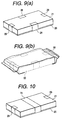
- Fig. 9 (a) the package main body 20 and upper cover 21 are fixed together by adhesive tapes 28 and 29 to complete a package, and then, as shown in Fig. 9 (b), the package is enclosed into an ink leakage preventive bag 30.
- Fig. 10 if an adhesive tape 31 is wound entirely around the longitudinal central portions of the package main body 20 and upper cover 21 to thereby fix them, then the tensile force of the adhesive tape 31 can prevent the package main body 20 and upper cover 21 from being expanded.
- the depth L1 of the package main body 20 is set smaller than the thickness d of the ink bag 19, preferably, in such a manner that L1 ⁇ (0.7 - 1.0) d, then the upper cover 21 and package main body 20 are closely contacted with the front and back surfaces of the ink bag 19 respectively, which makes it possible not only to prevent the ink bag 19 from being twisted or bent due to shocks or the like but also to prevent the ink bag 19 from oscillating when vibrations are given to the package.
- the attached portions 19h on the short-side side of the ink bag 19 can be held by and between the end portion packing members 22 to 25 more positively as well as the inclined surfaces of the end portion packing members 22 to 25 are respectively contacted with the shoulder portions 19a to 19d of the ink bag 19. Accordingly, the shape of the ink bag 19 can be maintained.
- the package main body 20 and upper cover 21 are both closely contacted with the surfaces of the ink bag 19 to thereby be able to positively prevent the ink bag 19 from being twisted and oscillated due to shocks and vibrations.
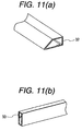
- the inner packing members 22 to 27 are each made of foaming material.
- the inner packing members 22 to 27 are structured by bending plate members 32, 33 such as cardboard plates or the like or by injection molding high-molecular material into a cylindrical shape, they can also provide similar effect.
- Figs. 12 (a) and (b) show another embodiment of a package according to the invention.
- a plate member suitable for packing of an ink bag such as a cardboard plate, a high-molecular material member or the like is cut into a predetermined shape that has a top plate 40, a bottom plate 41, and side plates 42, 43, 44, 45 and that can be formed into a box-like shape.
- the end portion inner packing members 24, 25 and 22, 23 are fixed by adhesives or the like to the longitudinal end portions of the top plate 40 and bottom plate 41 at given positions to hold the end portions of the ink bag 19.
- the ink leakage preventive bag 30 is structured as a vacuum pack.
- the ambient air pressure is allowed to act uniformly on the outer peripheries of the top plate 40, bottom plate 41, and side plates 42, 43, 44, 45 and, concurrently, resisting forces of the end portion inner packing members 22 to 25 are applied to the inner surfaces of the plates 40 to 45, thereby being able to maintain the box shape.
- a package 50 is made up of a box-shaped main body portion 51 and a cover portion 52 continuous with the one side of the main body portion 51; recesses 51a and 52a serving as windows from which the ink supply hole forming member 5 can be exposed are formed on the overlapping side of the main body portion 51 and cover portion 52; and a recess 24a is formed on one of the end portion inner packing members 22 and 24 situated on the side of the ink supply hole forming member 5.
- the end portion inner packing members 22, 24 and 23, 25 are mounted onto the longitudinal end portions of the ink bag 19, and the side surface inner packing members 27 (26) are mounted onto the side surfaces of the ink bag 19; if necessary, after secured provisionally, these packing members and ink bag are stored into the main body portion 51; and, the cover portion 52 is closed, thereby completing the package 50.
- the package 50 may be stored into the ink leakage preventive bag 30, and the ink leakage preventive bag 30 may be structured as a vacuum pack.
- the ambient air pressure is allowed to act uniformly on the outer peripheries of the main body portion 51 and cover portion 52 whereas the resisting forces of the end portion inner packing members 22 to 25 act on the inner surfaces of the main body portion 51 and cover portion 52, thereby being able to maintain the box shape of the package 50.
- the ink bag 19 is taken out from the ink leakage preventive bag 30 or the vacuum pack 30, then the ink bag 19 can be mounted to the recording apparatus in a state that the ink bag 19 is stored within the package 50.
- the ink bag 19 is constructed such that the second films 3 and 4 are disposed on the longer sides of the first films 1 and 2, and the ink supply hole forming member 5 is disposed on the shorter sides of the first films 1 and 2.
- the present invention should not be restricted thereto or thereby.
- the ink bag 19 may be constructed such that the second films 3 and 4 are disposed on the shorter sides of the first films 1 and 2, and the ink supply hole forming member 5 is disposed on the longer sides of the first films 1 and 2.
- each of the first films 1 and 2 may be formed to have a regular rectangular shape or a perfect square shape.
- each of the first films 1 and 2 may be formed to have a trapezoidal shape.
- the thermal fusion is utilized to combine the first films 1 and 2, the second films 3 and 4 and the supply hole forming member 5 together.
- the thermal fusion simplifies the manufacturing process for the ink bag 19, the present invention should not be restricted thereto or thereby, and any suitable attachment method, such as adhesive, may be applied in place of the thermal fusion.
Abstract
Description
- The present invention relates to an ink container which is removably accommodated in a casing of an ink jet type recording apparatus to supply ink to a recording head and, in more particular, to a flexible ink bag for storing ink therein.
- An ink jet type recording apparatus performs a printing operation by reciprocating a recording head in the sheet width direction of a recording sheet. To supply ink from an ink supply source to the recording head while reducing the weight of a reciprocatingly moving section, a recording apparatus, which carries out a large amount of print, generally adopts an arrangement in which the ink supply source is disposed in a casing of the apparatus whereas ink is supplied through a tube to the recording head.
- The ink jet type recording apparatus is designed to pressurize ink in a pressure generation chamber to thereby generate ink droplets. If the ink contains air bubbles therein, then the pressure generated is reduced due to such air bubbles to lower the ejection performance of the ink droplets. In order to avoid this problem, the ink jet type recording apparatus requires ink which eliminates dissolved air therefrom.
- For this reason, an
ink bag 60 shown in Fig. 14 is formed in the following manner: That is, a laminated film having a gas barrier property, which is composed of a polyethylene film and aluminum vapor-deposited on the polyethylene film, is folded at its center so that two half sections of the laminated film are superimposed one on the other. The three sides of the thus superimposed laminated film except for one short side thereof are connected together by thermal fusion or any other suitable processing. The remaining one short side is sealed with an ink supplyhole forming member 61 made of a plastic molding be secured thereto. Further, in order to protect theink bag 60 from damage due to an external force or the like and to form an ink cartridge, theink bag 60 is stored in ahard case 62 formed of high-molecular material. In Fig. 14,reference numeral 63 designates a plate member to be fixed to one side of theink bag 60 to deform theink bag 60 uniformly and enable detection of the ink end, and 64 designates a cover forming a part of thehard case 62. - However, the ink bag for commercial printing purpose must be supplied or distributed to a user without being stored in the hard case because the capacity of the
ink bag 60 must be increased as well as the cost thereof must be reduced. - Therefore, the ink bag itself is required to have such strength as to withstand the distribution and a setting operation for setting the ink bag into a recording apparatus, but the increased strength of the ink bag hinders smooth reduction of the capacity of the bag in conjunction with the ink consumption by printing, which, in turn, incurs an obstacle to the supply of ink to the recording head. The ink bag, which is filled with ink, has such a rounded shape that the central portion of the ink bag is larger in thickness than the peripheral portions thereof, and therefore the accommodation of the relatively rounded ink bag into an easy-to-handle rectangular case arises another problem in that space utility is low due to the presence of a dead space.
- Moreover, if the ink storage capacity of the ink bag is increased, then the shaking or rocking motion of the ink during the distribution causes greater shocks to the ink bag, so that the ink bag is easy to break.
- Accordingly, it is a first object of the invention to provide an ink bag which can secure such degree of strength as to be able to protect the ink bag from damage in handling when it is loaded into a recording apparatus.
- A second object of the present invention is to provide an ink bag which can maintain its rectangular shape by itself in its ink filled state to thereby provide a high ink filling efficiency.
- A third object of the present invention is to provide an ink bag which can supply ink to the recording apparatus positively.
- A fourth object of the invention is to provide an ink bag which provides a rectangular shape in its ink filled state to thereby allow it to be stored in a recording apparatus with only a small dead space produced.
- A fifth object of the invention is to provide an ink bag, which is able to receive external forces acting on the four corners of the ink bag in such a manner that the external forces are dispersed by four connecting portions formed in their associated four corners of the ink bag to thereby able to prevent the ink bag against damage as much as possible.
- A sixth object of the invention is to provide an ink bag, which, according to the ink amount, can reduce the thickness of the side surface portions of the ink bag having relatively weak rigidity due to tensile forces given from connecting portions of the four corners of the ink bag to thereby be able to discharge ink positively.
- A seventh object of the invention to provide a package for packing therein an ink bag in such a manner that the side surface portions of the ink bag are supported and held by and between the side surface inner packing members of the package, and the shoulder portions of the ink bag are supported and held by and between the end portion inner packing members of the package to eliminate a space for oscillation of the ink bag, thereby being able to prevent the ink bag from being damaged by large shocks that could be possibly applied to the ink bag during distribution.
- An ink bag according to a preferred embodiment of the invention is structured such that, to the respective long side portions of a rectangular-shaped, thermally fusible first film forming the surface portions of the ink bag, there are attached, by thermal fusion, the long side portions of a rectangular-shaped, thermally fusible second film forming the side surface portions of the ink bag and having lower rigidity than the first film to thereby form a cylindrical body. The one-side short side portions of the surface portions of the ink bag are attached together by thermal fusion to thereby form a bag body. An ink supply hole forming member is attached by thermal fusion to the other-side short side portions of the surface portions of the ink bag. In the four corners of the ink bag, there are formed strip-like connecting portions each starting from one of the two mutually adjoining sides of the ink bag and reaching the other of the two sides.
- An ink bag package according to a preferred embodiment of the invention includes end portion inner packing members, each having a trapezoidal-shaped section, for holding between them the end portion areas of the short-side sides of the ink bag from both surfaces thereof. The package further includes rectangular-shaped side surface inner packing members to be respectively contacted with the side surfaces of the long-side sides of the ink bag. A container is provided for storing therein theses inner packing members together with the ink bag.
- The present disclosure relates to the subject matter contained in Japanese patent application Nos. Hei. 10-367539 (filed on December 24, 1998) and Hei. 11-234916 (filed on August 23, 1999), which are expressly incorporated herein by reference in their entireties.
-
- Figs. 1 (a) and (b) are respectively a perspective view and a partially cutaway perspective view of an ink bag according to an embodiment of the invention;
- Figs. 2 (a) and (b) are respectively a side view of the ink bag, showing its ink filled state, and a top view thereof, showing its folded state;
- Figs. 3 (a) and (b) are sectional views taken along a line 3-3 of Fig. 1(a), showing two examples for a corner portion;
- Figs. 4 (a), (b), (c) and (d) are section views of examples for a film used to form the ink bag;
- Figs. 5 (I), (II) and (III) are sectional views taken along a line 5-5 of Fig. 1, showing deforming steps of the ink bag in conjunction with reduction of ink amount;
- Fig. 6 is a top surface view of an ink bag in its folded state according to another embodiment of the invention;
- Fig. 7 is a perspective view of a package suitable for an ink bag, which constitutes an embodiment of the invention;
- Figs. 8 (a) and (b) are a section view taken along the long-side side of the package and a section view taken along the short-side side thereof, showing a state in which the ink bag is packed by the above package;
- Figs. 9 (a) and (b) are perspective views of the above package, showing respective packing steps in which the ink bag is packed by and into the package;
- Fig. 10 is a perspective view of a package according to the invention;
- Figs. 11 (a) and (b) are respectively views of examples of the end portion inner packing member and side portion inner packing member used in the package of the invention;
- Figs. 12 (a) and (b) are perspective views of another package according to the invention, showing their packing steps respectively;
- Fig. 13 shows a perspective view of yet another package according to the invention, showing a state in which an ink bag is taken out therefrom; and,
- Fig. 14 is a perspective view showing an assembly of a related ink bag.
-
- Now, Figs. 1 (a), (b) and Figs. 2 (a), (b) show an
ink bag 19 according to an embodiment of the invention. Theink bag 19 has firstrectangular films rectangular films 3 and 4 as side surfaces, and an ink supplyhole forming member 5. The secondrectangular films 3 and 4 are lower in rigidity than the firstrectangular films rectangular films 3 and 4 may be folded, for instance, along a center line C, may be formed by selecting different material than the firstrectangular films ink bag 19 is formed, preferably, by the following procedure: Thefirst films second film 3 and 4 each folded along the center line C are interposed therebetweeen. Thelong side portions first films long side portions second films 3 and 4, for instance, by thermal fusion, to thereby form a hollow assembly. One end of the hollow assembly is closed, whereas the ink supplyhole forming member 5 is attached to the other end of the hollow assembly. In this embodiment, the central portions of theshort side portions first films short side portions first films second films 3 and 4. Further, in this embodiment, the central portion of theshort side portion 1d of thefirst film 1 is attached by thermal fusion to either of the central portion of theshort side portion 2d of thefirst film 2 and the outer periphery of the ink supplyhole forming member 5, the central portion of theshort side portion 2d of thefirst film 2 is attached by thermal fusion to either of the central portion of theshort side portion 1d of thefirst film 1, and the remaining portions of theshort side portions first films second films 3 and 4. The half of the second film 3 (4) with respect to the central line C, which extends along theshort side 1c, may be attached to the other half of the second film 3 (4) or may be separated therefrom. Theink bag 19 of this embodiment is further formed with connectingportions 6 to 9 at its four corners. Each of the connectingportions 6 to 9 is formed, by thermal fusion, as a strip extending obliquely from one side of theink bag 19 to another adjacent side of theink bag 19 and across the folding line D (i.e. the central line C) as best shown in Fig. 2. - As shown in Fig. 6, the connecting
portions 6 to 9 may be formed not to extend across the folding lines D'. However, the former case in which the folding lines D of thesecond films 3 and 4 are situated on the connectingportions 6 to 9 as shown in Fig. 2 is advantageous, from the viewpoint of reinforcement, over the latter case in which the folding lines D' of thesecond films 3 and 4 are situated inwardly of the connectingportions 6 to 9 as shown in Fig. 6, since the connecting portions 6-9 of the former case can more positively reinforce the areas E of theink bag 19, where thefirst films second film 3 or 4 are overlapped together in a complicated manner. As shown in Fig. 3(a), each of the connectingportions 6 to 9 is formed such that thefirst films second film 3 or 4 at thermally fused areas a. That is, the thermally fused areas a is located between mutually contacting surfaces of the first film 1 (2) and the second film 3 (or 4) within the interior of theink bag 19. The connecting portion 6 (to 9) of this arrangement can provide sufficient strength to theink bag 19, but if larger strength is required, then it is preferable to further attach the half of the second film 3 (4) to the other half of the second film 3 (4) as illustrated by a thermally fused area b in Fig. 3(b). That is, in Fig. 3(b), the mutually contacting surfaces of the halves of the second film 3 (4), which are located outside theink bag 19, are attached to each other at the thermally fused area b. - Each of the
first films polyethylene layer 10 of about 100 µm thickness, apolyester layer 11 of about 25 µm thickness, a gas-impermeable and flexible metal layer, such as analuminum layer 12, of about 15 µm thickness, and, a protective layer, such as apolyester layer 13, of about 38 µm thickness. Each of thesecond films 3 and 4 preferably has such a laminated structure as shown in Fig. 4 (b), which includes apolyethylene layer 15 of about 60 µm thickness, a gas-impermeable and flexible metal layer, such asaluminum layer 16, of about 9 µm thickness, and a protective layer, such as aflexible nylon layer 17, of about 15 µm to 25 µm thickness. As shown in Fig. 4 (c), thesecond film 3, 4 may further has anothernylon layer 18 interposed between thepolyethylene layer 15 andaluminum layer 16. - Since polyethylene can provide excellent adhering property as a consequence of thermal fusion, the above-exemplified laminated structure for the
films ink bag 19 having sufficient connection strength and sufficient airtightness using the thermal fusion. Thepolyethylene layer 10 of the each of thefirst film second films 3 and 4 in a state that each of thesecond films 3 and 4 has been folded at the central line C and aligned to thefirst films polyethylene layer 10 of thefirst film 1 is attached by thermal fusion to thepolyethylene layer 15 of thesecond film 3 but thenylon layer 17 on the half of thesecond film 3 should not be attached to thenylon layer 17 of the other half of thesecond film 3 as in the case for the portion X marked in Fig. 1 (a), then the heat to be applied to the first andsecond films polyethylene layer 10 of thefirst film 1 is attached to thepolyethylene layer 15 of thesecond film 3 and thenylon layer 17 on the half of thesecond film 3 is also attached to thenylon layer 17 of the other half of thesecond film 3, then the heat to be applied to the first andsecond films second film 3 may be selected in place of thenylon layer 17. - After degassed ink is filled through an ink supply hole of the ink supply
hole forming member 5 into theink bag 10 thus formed, the ink supply hole is sealed by a septum. Theink bag 19 filled completely with ink is inflated or expanded into a relatively flat and substantially parallelepiped shape as shown in Fig. 5 (I) while the connecting portions 6 - 9 at four corners and theshort side portions ink bag 19 prevent unnecessary expansion of theink bag 19. In this state, even if the ink bag is given an excessive force due to its fall or the like, the four corners of theink bag 19 is protected by the relatively wide connectingportions 6 to 9 which serve to disperse the applied excessive force. Therefore, theink bag 19 is free from the damage. - Because the stored ink is in contact with the chemically stable polyethylene layers 10 and 15, the ink remains unchanged chemically. Further, since the aluminum layers 12 and 16 isolate the ink inside the ink bag from ambient air, the degassed condition of the ink can be maintained for a long period of time. That is, the quality of the ink applied when it is shipped from a factory can be maintained for a long time.
- When an ink supply needle disposed in a recording apparatus is inserted into the ink supply hole of the
member 5, the ink in the ink bag is supplied through an ink supply tube to a recording head. As the consumption of the ink by the recording head advances, the relatively weak side surface portions, i.e. thefilms 3 and 4, are deformed in conjunction with the consumed amount of the ink to reduce the thickness of theink bag 19. In particular, since each of thefilms 3 and 4 has such a tendency as to be deformed along the central line C and the connectingportions 6 to 9 effectively serve to transmit tensile forces from thefirst films second films 3 and 4 to move the center lines C of thesecond films 3 and 4 inwardly, the thickness reduction of theink bag 19 in conjunction with the ink consumed amount is facilitated (Fig. 5 (II)). At the final stage in which the ink is consumed completely, the side surface portions, i.e. thesecond films 3 and 4, are folded completely so that the half of the second film 3 (4) is contacted with the other half of the second film 3 (4) as well as the one of thefirst films first films - Fig. 4 (d) is another preferable example for each of the
first films intermediate polyester layer 11 in the structure shown in Fig. 4 (a) is replaced with a nylon layer 17'. This structure makes it possible to more positively prevent the damage and breakage of theink bag 19 caused due to the shaking or rocking motion of the ink, the impact applied to theink bag 19 or the like, since the nylon superior in breaking strength to polyester is incorporated as an intermediate layer to the laminated structure. In addition, the polyester layer 13 (and 11) serves to assist or facilitate the folding of theink bag 19 in conjunction with the ink consumption as described with reference to Fig. 5, since the polyester possesses a certain rigidity or tension. That is, the provision of the polyester layer 13 (and 11) makes it possible to surely discharge the ink from the interior of theink bag 19. - Fig. 7 shows an example of a package which is preferably used to pack the above-mentioned
ink bag 19 to improve the handling of theink bag 19 during distribution to a user. Note that theink bag 19 shown in Fig. 7 is not formed with the connectingportions 6 to 9, but may have the connectingportions 6 to 9 similarly to theink bag 19 shown in Fig. 1. The present package comprises an outer packing member, which is composed of a box-shaped containermain body 20 having a depth L1 smaller than the thickness d of theink bag 19 and a box-shapedupper cover 21, four end portioninner packing members ink bag 19 on the long-side side thereof and each having a trapezoidal-shaped section, and two side surfaceinner packing members ink bag 19. - The four end portion
inner packing members 22 to 25 are structured such that, when the pair of theinner packing members 22 and 24 (or the pair of theinner packing members 23 and 25) hold the end portion (short side) 19h of theink bag 19 therebetween to be respectively contacted with the upper and lower surfaces of theend portion 19h, a total height L2 of the pair of the end portioninner packing members 22 and 24 (or 23 and 25) is larger than the depth L1 of the containermain body 20 and smaller than the maximum thickness d of theink bag 19. In the present embodiment, each of the end portioninner packing members 22 to 25 is manufactured by molding high-molecular foaming material into a trapezoidal cross-sectional shape to have a perpendicular surface on one end side and an inclined surface on the opposite side, which substantially matches with a corresponding one ofshoulder portions 19a to 19d of theink bag 19. Each of the side surface portioninner packing members ink bag 19, the surface of the side surface portion inner packing member 26 (27) is slightly protruded laterally from theink bag 19. - To pack the
ink bag 19 in the present embodiment, the end portioninner packing members main body 20 in such a manner the inclined surfaces thereof face upwardly. Thereafter, theink bag 19 is placed onto the thus placed end portioninner packing members inner packing members ink bag 19. Thereafter, the end portioninner packing members main body 20 with their inclined surfaces facing downward, and anupper cover 21 is then set onto the containermain body 20. - Accordingly, as shown in Figs. 8 (a) and (b), the
ink bag 19 is stored within and between the packagemain body 20 andupper cover 21 in such a manner that theside surface portions 3 and 4 of theink bag 19 are restricted by the side surfaceinner packing members portions 19g of theink bag 19 are situated laterally inward of the upper or lower surfaces of the side surfaceinner packing members shoulder portions 19a to 19d of theink bag 19 are respectively supported by their associated end portioninner packing members 22 to 25, and the attachedportions 19h of theink bag 19 are held by and between their associated end portioninner packing members 22 to 25. - In this state, as shown in Fig. 9 (a), the package
main body 20 andupper cover 21 are fixed together byadhesive tapes preventive bag 30. As shown in Fig. 10, if anadhesive tape 31 is wound entirely around the longitudinal central portions of the packagemain body 20 andupper cover 21 to thereby fix them, then the tensile force of theadhesive tape 31 can prevent the packagemain body 20 andupper cover 21 from being expanded. - By the way, if the depth L1 of the package
main body 20 is set smaller than the thickness d of theink bag 19, preferably, in such a manner that L1 ≤ (0.7 - 1.0) d, then theupper cover 21 and packagemain body 20 are closely contacted with the front and back surfaces of theink bag 19 respectively, which makes it possible not only to prevent theink bag 19 from being twisted or bent due to shocks or the like but also to prevent theink bag 19 from oscillating when vibrations are given to the package. - Further, since the total height L2 of the pair of the end portion
inner packing members 22 and 24 (23 and 25) is set larger than the depth L1 of the packagemain body 20, the attachedportions 19h on the short-side side of theink bag 19 can be held by and between the endportion packing members 22 to 25 more positively as well as the inclined surfaces of the endportion packing members 22 to 25 are respectively contacted with theshoulder portions 19a to 19d of theink bag 19. Accordingly, the shape of theink bag 19 can be maintained. - Further, because the total height L2 of the pair of the end portion
inner packing members 22 and 24 (23 and 25) is set smaller than the maximum thickness d of theink bag 19, the packagemain body 20 andupper cover 21 are both closely contacted with the surfaces of theink bag 19 to thereby be able to positively prevent theink bag 19 from being twisted and oscillated due to shocks and vibrations. - In the above-mentioned embodiment, the
inner packing members 22 to 27 are each made of foaming material. However, as shown in Figs. 11 (a) and (b), even if theinner packing members 22 to 27 are structured by bendingplate members - Now, Figs. 12 (a) and (b) show another embodiment of a package according to the invention. In the present embodiment, a plate member suitable for packing of an ink bag such as a cardboard plate, a high-molecular material member or the like is cut into a predetermined shape that has a
top plate 40, abottom plate 41, andside plates inner packing members top plate 40 andbottom plate 41 at given positions to hold the end portions of theink bag 19. - Side surface
inner packing members ink bag 19 and they are all placed onto thebottom plate 41. As shown in Fig. 12 (b), thetop plate 40 andside plate 43 having its short-side side opened are folded, and the connecting portion between thetop plate 40 andside plate 43 is fixed usingadhesive tape 46. Then, theside plates side plates top plate 40 are provisionally secured to each other by adhesive tape. Thereafter, similarly to the case shown in Fig.9 (b), theink bag 19 and package are enclosed into an ink leakagepreventive bag 30. - Especially, it is preferably that the ink leakage
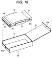
preventive bag 30 is structured as a vacuum pack. In this case, the ambient air pressure is allowed to act uniformly on the outer peripheries of thetop plate 40,bottom plate 41, andside plates inner packing members 22 to 25 are applied to the inner surfaces of theplates 40 to 45, thereby being able to maintain the box shape. - In the above-mentioned embodiment, the package is formed or molded into a developed shape. However, according to the invention, it is also possible to employ such an embodiment as shown in Fig. 13: that is, a
package 50 is made up of a box-shapedmain body portion 51 and acover portion 52 continuous with the one side of themain body portion 51;recesses hole forming member 5 can be exposed are formed on the overlapping side of themain body portion 51 andcover portion 52; and arecess 24a is formed on one of the end portioninner packing members hole forming member 5. - In this embodiment, the end portion
inner packing members ink bag 19, and the side surface inner packing members 27 (26) are mounted onto the side surfaces of theink bag 19; if necessary, after secured provisionally, these packing members and ink bag are stored into themain body portion 51; and, thecover portion 52 is closed, thereby completing thepackage 50. After then, similarly to the above-mentioned embodiment, thepackage 50 may be stored into the ink leakagepreventive bag 30, and the ink leakagepreventive bag 30 may be structured as a vacuum pack. - According to the present embodiment, similarly to the above-mentioned embodiment, the ambient air pressure is allowed to act uniformly on the outer peripheries of the
main body portion 51 andcover portion 52 whereas the resisting forces of the end portioninner packing members 22 to 25 act on the inner surfaces of themain body portion 51 andcover portion 52, thereby being able to maintain the box shape of thepackage 50. And, if theink bag 19 is taken out from the ink leakagepreventive bag 30 or thevacuum pack 30, then theink bag 19 can be mounted to the recording apparatus in a state that theink bag 19 is stored within thepackage 50. - In the aforementioned embodiments, the
ink bag 19 is constructed such that thesecond films 3 and 4 are disposed on the longer sides of thefirst films hole forming member 5 is disposed on the shorter sides of thefirst films ink bag 19 may be constructed such that thesecond films 3 and 4 are disposed on the shorter sides of thefirst films hole forming member 5 is disposed on the longer sides of thefirst films first films first films - In the aforementioned embodiments, the thermal fusion is utilized to combine the
first films second films 3 and 4 and the supplyhole forming member 5 together. Although the thermal fusion simplifies the manufacturing process for theink bag 19, the present invention should not be restricted thereto or thereby, and any suitable attachment method, such as adhesive, may be applied in place of the thermal fusion.
Claims (28)
- An ink bag for an ink jet type recording apparatus, the ink bag comprising:a pair of first films, each having first opposing sides, and second opposing sides each connecting the first opposing sides;a pair of second films, each having third opposing sides, and fourth opposing sides each connecting the third opposing side, wherein the second films are lower in rigidity than the first films, and the third sides of each second film are respectively attached to a corresponding first side of one of the first films and a corresponding first side of the other of the first films; andan ink supply hole forming member attached to a corresponding one of the second sides of each first film;
wherein the rest of the second sides of one first film is partially attached to the rest of the second sides of the other first film. - The ink bag according to claim 1, further comprising:connecting portions disposed at respective corners of the first films, each of the connecting portions being in the form of a strip and connecting the first sides of the first films to the second sides of the first films.
- The ink bag according to claim 2, wherein each of the connecting portions connects mutually contacting surfaces of the first and second films.
- The ink bag according to claim 2, wherein each of the connecting portions connects mutually contacting surfaces of the first and second films and mutually contacting surfaces of a corresponding second film.
- The ink bag according to claim 1, wherein each of the second films has a central line at which the second film is likely to be folded.
- The ink bag according to claim 2, wherein each of the second films has a central line at which the second film is likely to be folded, and the central line of each second film extends across corresponding connecting portions when the second film is folded.
- The ink bag according to claim 1, wherein each of the first films has a laminated structure including a polyethylene layer, a polyester layer, a metal layer and another polyester layer laminated one on another in this order, and each of said second film has a laminated structure including a polyethylene layer, a metal layer and a nylon layer laminated one on another in this order, wherein mutually contacting surfaces of the polyethylene layers are attached together by thermal fusion.
- The ink bag according to claim 7, wherein a nylon layer is interposed between the polyethylene layer and the metal layer.
- The ink bag according to claim 1, wherein each of the first and second films is thermally fusible.
- The ink bag according to claim 1, wherein the first sides of the first films are longer in length than the second sides of the first films.
- An ink bag package for an ink jet type recording apparatus, comprising:the ink bag of claim 1;end portion inner packing members, each having a trapezoidal-shaped section, and each disposed on a respective one of the second sides of the first films;side surface inner packing members each disposed between the first films and each contacted with a respective one of the second films; and,a container storing therein the ink bag, and the packing members.
- The ink bag package according to claim 11, wherein the container includes a box-shaped container main body and a box-shaped upper cover, and a depth L1 of the container main body is smaller than a maximum thickness d of the ink bag.
- The ink bag package according to claim 12, wherein a vertical total height L2 of the end portion inner packing members of a pair vertically holding a second side of one first film and a corresponding second side of the other first film therebetween is larger than the depth L1 of the container main body and smaller than the maximum thickness d of the ink bag.
- The ink bag package according to claim 13, further comprising:an adhesive tape fixing the container main body and the upper cover to each other.
- The ink bag package according to claim 12, further comprising:an adhesive tape circumscribing longitudinally central portions of the container main body and the upper cover, to thereby fix the container main body and the upper cover to each other.
- The ink bag package according to claim 11, further comprising:a vacuum pack enclosing the container therein.
- The ink bag package according to claim 11, wherein each of the side surface inner packing members is rectangular in section.
- A method of manufacturing the ink bag of claim 1, comprising the steps of:(a) attaching the third sides of each second film to a corresponding first side of one of the first films and a corresponding first side of the other of the first films by thermal fusion to thereby form a cylindrical body having openings at respective ends;(b) applying heat to one of the openings to close the one of the openings by thermal fusion; and(c) applying heat to the other of the openings to sealingly attach the ink supply hole forming member to the other of the openings by thermal fusion to thereby form an ink bag.
- The method according to claim 18, further comprising:attaching mutually contacting surfaces of an inner side of the ink bag at four corner portions of the ink bag, to thereby provide connecting portions connecting the first sides of the first films to the second sides of the first films.
- The method according to claim 18, further comprising:attaching mutually contacting surfaces of an inner side of the ink bag at four corner portions of the ink bag and attaching mutually contacting surfaces of an outer side of the ink bag at the four corner portions of the ink bag, to thereby provide connecting portions connecting the first sides of the first films to the second sides of the first films.
- The method according to claim 18, wherein said steps (a), (b) and (c) is carried out such that the first films are aligned together in a state that the second films each folded along a center line are interposed therebetweeen, and heat is then applied to the first to fourth sides of the first and second films.
- The ink bag according to claim 1, wherein each of said first films is rectangular.
- The ink bag according to claim 1, wherein each of said second films is rectangular.
- The ink bag according to claim 22, wherein said first sides are longer than said second sides.
- The ink bag according to claim 22, wherein said first sides are shorter than said second sides.
- The ink bag according to claim 22, wherein each of said first films is a perfect square.
- The ink bag according to claim 22, wherein each of said first films is trapezoidal.
- The ink bag according to claim 1, wherein each of the first films has a laminated structure including a polyethylene layer, a nylon layer, a metal layer and a polyester layer laminated one on another in this order.
Applications Claiming Priority (4)
| Application Number | Priority Date | Filing Date | Title |
|---|---|---|---|
| JP36753998 | 1998-12-24 | ||
| JP36753998 | 1998-12-24 | ||
| JP23491699A JP3700168B2 (en) | 1999-08-23 | 1999-08-23 | Ink bag packaging material for inkjet recording apparatus |
| JP23491699 | 1999-08-23 |
Publications (3)
| Publication Number | Publication Date |
|---|---|
| EP1013449A2 true EP1013449A2 (en) | 2000-06-28 |
| EP1013449A3 EP1013449A3 (en) | 2000-12-06 |
| EP1013449B1 EP1013449B1 (en) | 2007-02-14 |
Family
ID=26531844
Family Applications (1)
| Application Number | Title | Priority Date | Filing Date |
|---|---|---|---|
| EP99125921A Expired - Lifetime EP1013449B1 (en) | 1998-12-24 | 1999-12-23 | Ink bag for ink jet type recording apparatus and package suitable for packing such ink bag |
Country Status (5)
| Country | Link |
|---|---|
| US (1) | US6220702B1 (en) |
| EP (1) | EP1013449B1 (en) |
| AT (1) | ATE353764T1 (en) |
| DE (1) | DE69935117T2 (en) |
| HK (1) | HK1029962A1 (en) |
Cited By (10)
| Publication number | Priority date | Publication date | Assignee | Title |
|---|---|---|---|---|
| FR2822808A1 (en) * | 2001-03-30 | 2002-10-04 | Valois Sa | FLUID PRODUCT DISPENSING ASSEMBLY |
| EP1375161A2 (en) | 2002-06-28 | 2004-01-02 | Océ-Technologies B.V. | Ink tank |
| NL1023215C2 (en) | 2003-04-17 | 2004-10-19 | Stork Digital Imaging Bv | Pressure device, flexible supply holder and work holder, as well as supply system. |
| US6811057B2 (en) | 2001-03-30 | 2004-11-02 | Valois S.A.S. | Fluid dispenser assembly |
| WO2005000079A1 (en) * | 2003-06-27 | 2005-01-06 | Koninklijke Philips Electronics, N.V. | A pouch with side gussets for use in carrying fluid for personal hygiene device |
| EP1510346A2 (en) | 2003-08-08 | 2005-03-02 | Seiko Epson Corporation | Liquid container |
| US6874879B2 (en) | 2002-06-28 | 2005-04-05 | Oce-Technologies B.V. | Ink tank |
| US20120120166A1 (en) * | 2008-02-20 | 2012-05-17 | Seiko Epson Corporation | Liquid Container |
| CN104010821A (en) * | 2011-12-21 | 2014-08-27 | 精工爱普生株式会社 | Liquid container |
| EP3962753A4 (en) * | 2019-08-02 | 2022-11-30 | Hewlett-Packard Development Company, L.P. | Intermediate tank for continuous fluid delivery |
Families Citing this family (79)
| Publication number | Priority date | Publication date | Assignee | Title |
|---|---|---|---|---|
| JP4193719B2 (en) * | 2003-03-05 | 2008-12-10 | セイコーエプソン株式会社 | Liquid container, liquid ejecting apparatus, and liquid container case |
| US6270207B1 (en) * | 1998-03-30 | 2001-08-07 | Brother Kogyo Kabushiki Kaisha | Ink cartridge and remaining ink volume detection method |
| TW471394U (en) * | 1999-09-09 | 2002-01-01 | Wisertek Internat Corp | Structure for ink cartridge with negative pressure |
| US6695757B2 (en) * | 2001-01-12 | 2004-02-24 | Scholle Corporation | Method of manufacturing a standup bag |
| EP1412167A4 (en) * | 2001-02-21 | 2007-08-08 | Tilia Int Inc | Method for preparing air channel-equipped film for use in vacuum package |
| US6786583B2 (en) * | 2001-08-30 | 2004-09-07 | Seiko Epson Corporation | Ink cartridge storage structure and method |
| JP2003118140A (en) * | 2001-10-16 | 2003-04-23 | Seiko Epson Corp | Pressure reduced packaged ink cartridge and pressure reduced packaging method |
| JP2003220710A (en) * | 2002-01-29 | 2003-08-05 | Noritsu Koki Co Ltd | Replenishment liquid cartridge |
| WO2003066473A1 (en) * | 2002-02-04 | 2003-08-14 | Manchiu Li | Vacuum storage bag |
| AU2003215115A1 (en) * | 2002-02-07 | 2003-09-02 | Scholle Corporation | An internal brace for a standup flexible container |
| AU2003224903A1 (en) * | 2002-04-27 | 2003-11-17 | River Solutions, Inc. | Gusseted flexible bottle with fitment and method of fabrication |
| US6832852B2 (en) * | 2002-04-27 | 2004-12-21 | Kenneth R. Wilkes | Gusseted flexible bottle with fitment and method of fabrication |
| US6696959B2 (en) * | 2002-07-19 | 2004-02-24 | Hewlett-Packard Development Company, L.P. | Broken bag sensing feature for a metallized ink bag |
| US6830323B2 (en) * | 2002-08-13 | 2004-12-14 | Eastman Kodak Company | Restricting flash spread when welding housing halves of cartridge together |
| US7093710B2 (en) * | 2002-10-31 | 2006-08-22 | Brother Kogyo Kabushiki Kaisha | Ink-package assembly, and method of producing the same |
| JP3919734B2 (en) * | 2002-12-06 | 2007-05-30 | 株式会社リコー | Ink cartridge, casing thereof, and image forming apparatus |
| US20050036717A1 (en) * | 2003-03-05 | 2005-02-17 | Tilia International, Inc. | Sealable bag having an integrated zipper for use in vacuum packaging |
| US20050036719A1 (en) * | 2003-03-05 | 2005-02-17 | Tilia International, Inc. | Sealable bag having an indicia for use in vacuum packaging |
| US7087130B2 (en) * | 2003-03-05 | 2006-08-08 | Tilia International, Inc. | Method for manufacturing a sealable bag having an integrated zipper for use in vacuum packaging |
| US20050036718A1 (en) * | 2003-03-05 | 2005-02-17 | Tilia International, Inc. | Sealable bag having an integrated valve structure for use in vacuum packaging |
| US20050065007A1 (en) * | 2003-03-05 | 2005-03-24 | Tilia International, Inc. | Method for manufacturing a sealable bag having an integrated valve structure for use in vacuum packaging |
| US20050043158A1 (en) * | 2003-03-05 | 2005-02-24 | Tilia International, Inc. | Method for manufacturing a sealable bag having an integrated timer/sensor for use in vacuum packaging |
| US20050037164A1 (en) * | 2003-03-05 | 2005-02-17 | Tilia International, Inc. | Liquid-trapping bag for use in vacuum packaging |
| US20050035020A1 (en) * | 2003-03-05 | 2005-02-17 | Tilia International, Inc. | Sealable bag having an integrated tray for use in vacuum packaging |
| US20050029704A1 (en) * | 2003-03-05 | 2005-02-10 | Tilia International, Inc. | Method for manufacturing a sealable bag having an indicia for use in vacuum packaging |
| US20050037163A1 (en) * | 2003-03-05 | 2005-02-17 | Tilia International, Inc. | Sealable bag having an integrated timer/sensor for use in vacuum packaging |
| US7138025B2 (en) * | 2003-03-05 | 2006-11-21 | Tilia International, Inc. | Method for manufacturing a sealable bag having an integrated tray for use in vacuum packaging |
| US7517484B2 (en) * | 2003-03-24 | 2009-04-14 | Sunbeam Products, Inc. | Forming evacuation channels during single and multi-layer extrusion process |
| JP4204373B2 (en) * | 2003-04-18 | 2009-01-07 | 株式会社リコー | Liquid container bag, liquid cartridge, image forming apparatus, liquid container bag sealing method, and sealing device |
| US20050031230A1 (en) * | 2003-08-07 | 2005-02-10 | Christopher Emst | Self standing flexible container |
| US7407326B2 (en) * | 2003-12-08 | 2008-08-05 | Wilkes Kenneth R | Triangularly shaped flexible bottle with fitment, and method of fabrication |
| US7220053B2 (en) * | 2003-12-16 | 2007-05-22 | Sunbeam Products, Inc. | Flexible composite bag for vacuum sealing |
| US20050157112A1 (en) | 2004-01-21 | 2005-07-21 | Silverbrook Research Pty Ltd | Inkjet printer cradle with shaped recess for receiving a printer cartridge |
| US7258432B2 (en) * | 2004-01-21 | 2007-08-21 | Silverbrook Research Pty Ltd | Inkjet printer cartridge with controlled refill |
| US7448734B2 (en) | 2004-01-21 | 2008-11-11 | Silverbrook Research Pty Ltd | Inkjet printer cartridge with pagewidth printhead |
| JP4478927B2 (en) * | 2004-03-10 | 2010-06-09 | セイコーエプソン株式会社 | Liquid container |
| US20050220942A1 (en) * | 2004-03-15 | 2005-10-06 | Hongyu Wu | Easy to peal vacuum packaging bags |
| US20060013514A1 (en) * | 2004-07-19 | 2006-01-19 | Hongyu Wu | Vacuum packaging bags with gussets and methods for using and manufacturing vacuum packaging bags with gussets |
| US7534039B2 (en) * | 2004-07-22 | 2009-05-19 | Sunbeam Products, Inc. | Vacuum packaging films patterned with protruding cavernous structures |
| US20060038863A1 (en) * | 2004-08-18 | 2006-02-23 | Eastman Kodak Company | Refillable chemical cartridge for photoprocessing equipment |
| US20060072860A1 (en) * | 2004-09-17 | 2006-04-06 | Hongyu Wu | Multi-layer film for forming a vacuum packaging bag and method of manufacture |
| US7488059B1 (en) * | 2004-11-02 | 2009-02-10 | Nu-Kote International, Inc. | Enclosure for ink reservoir bag |
| JP4665549B2 (en) * | 2005-02-25 | 2011-04-06 | ブラザー工業株式会社 | Packaging method of enclosure container with packaging package of enclosure container and packaging tool of packaging package |
| JP2006240131A (en) * | 2005-03-04 | 2006-09-14 | Brother Ind Ltd | Ink holding pack and ink cartridge |
| US20060201050A1 (en) * | 2005-03-09 | 2006-09-14 | Troutman Conrad M | Jig fishing lure |
| JP2008037015A (en) * | 2006-08-08 | 2008-02-21 | Seiko Epson Corp | Liquid storing bag and its manufacturing method |
| JP4337894B2 (en) * | 2007-03-14 | 2009-09-30 | セイコーエプソン株式会社 | Fluid container |
| JP4078387B1 (en) * | 2007-06-29 | 2008-04-23 | ワールドネットワーク株式会社 | Ink tank and ink cartridge |
| US20090027462A1 (en) * | 2007-07-24 | 2009-01-29 | Berg Richard H | Wide format ink cartridge |
| US8365954B2 (en) * | 2007-11-07 | 2013-02-05 | Gotohti.com, Inc. | Collapsible bottle and cover |
| JP5353565B2 (en) * | 2009-03-17 | 2013-11-27 | 株式会社リコー | Liquid container and image forming apparatus |
| JP5455755B2 (en) * | 2009-06-08 | 2014-03-26 | 株式会社セイコーアイ・インフォテック | Inkjet recording device |
| DE202010013614U1 (en) * | 2010-09-20 | 2010-11-25 | Lincoln Gmbh | Lubricant collecting container |
| CN108909192A (en) | 2010-10-27 | 2018-11-30 | 惠普发展公司,有限责任合伙企业 | Pressure bag |
| CN103282209B (en) | 2011-01-07 | 2015-07-15 | 惠普发展公司,有限责任合伙企业 | Fluid container having plurality of chambers and valves |
| US8646889B2 (en) | 2012-01-13 | 2014-02-11 | Seiko Epson Corporation | Cartridge and printing device |
| US9440755B2 (en) * | 2012-01-13 | 2016-09-13 | Seiko Epson Corporation | Liquid container and liquid consumption apparatus |
| US8960871B2 (en) | 2012-01-13 | 2015-02-24 | Seiko Epson Corporation | Mounting member, liquid container with mounting member, and liquid supply system |
| US8931887B2 (en) | 2012-01-13 | 2015-01-13 | Seiko Epson Corporation | Liquid consumption apparatus, liquid supply member, and liquid supply system |
| DE112013000550T5 (en) | 2012-01-13 | 2014-10-30 | Seiko Epson Corporation | Cartridge, printing material supply system, printing device, liquid receiving container, a printing system and a terminal connection structure |
| US9180673B2 (en) | 2012-04-30 | 2015-11-10 | Hewlett-Packard Development Company, L.P. | Liquid supply |
| US9162468B2 (en) * | 2012-04-30 | 2015-10-20 | Hewlett-Packard Development Company, L.P. | Liquid supply |
| US20130342618A1 (en) * | 2012-06-22 | 2013-12-26 | Tim Frasure | Fluid container having two sealing films for micro-fluid applications |
| JP6042177B2 (en) * | 2012-11-14 | 2016-12-14 | 株式会社ミマキエンジニアリング | Ink pack |
| JP5887295B2 (en) * | 2013-03-28 | 2016-03-16 | 京セラドキュメントソリューションズ株式会社 | Ink container and ink jet image forming apparatus |
| JP2014213567A (en) * | 2013-04-26 | 2014-11-17 | 京セラドキュメントソリューションズ株式会社 | Liquid storage container and ink jet type image formation device |
| DE102013214099A1 (en) | 2013-07-18 | 2015-01-22 | Wacker Chemie Ag | Packaging of polycrystalline silicon |
| FR3016870A1 (en) * | 2014-01-27 | 2015-07-31 | Lindal France Sas | TWO-WAY DISTRIBUTION DEVICE FOR CLOSING A BOTTLE |
| CN104842647B (en) * | 2014-02-13 | 2017-05-10 | 精工爱普生株式会社 | Recording apparatus |
| JP6372369B2 (en) * | 2014-03-31 | 2018-08-15 | ブラザー工業株式会社 | Liquid container |
| US10779507B2 (en) | 2014-04-21 | 2020-09-22 | Bark Pouch LLC | Pet treat dispensing container with cap fastener |
| GB2528910A (en) * | 2014-08-04 | 2016-02-10 | Smartwater Technology Ltd | Security apparatus |
| US9821284B2 (en) * | 2014-08-05 | 2017-11-21 | Jpro Dairy International, Inc. | Shaker bag mixing assembly |
| USD762015S1 (en) * | 2015-04-17 | 2016-07-19 | Bark Pouch LLC | Animal treat dispensing container |
| JP7147133B2 (en) | 2017-06-30 | 2022-10-05 | ブラザー工業株式会社 | liquid containment unit |
| JP2020044808A (en) * | 2018-09-21 | 2020-03-26 | セイコーエプソン株式会社 | Liquid storage container, liquid storage device and liquid jetting device |
| CN109693450A (en) * | 2019-01-17 | 2019-04-30 | 杭州专色数码科技有限公司 | Ink sac and ink jet printing device with the ink sac |
| JP7247695B2 (en) * | 2019-03-26 | 2023-03-29 | セイコーエプソン株式会社 | Liquid storage container and liquid discharge system |
| WO2023028044A1 (en) * | 2021-08-25 | 2023-03-02 | Entegris, Inc. | Rigid frame bags |
Citations (1)
| Publication number | Priority date | Publication date | Assignee | Title |
|---|---|---|---|---|
| JPH11234916A (en) | 1998-02-16 | 1999-08-27 | Rohm Co Ltd | Lithium ion battery pack |
Family Cites Families (28)
| Publication number | Priority date | Publication date | Assignee | Title |
|---|---|---|---|---|
| US2160816A (en) * | 1936-10-14 | 1939-06-06 | Mason Box Company | Container |
| US3595441A (en) * | 1968-09-03 | 1971-07-27 | Robert M Grosjean | Single-use container with dispensing spout |
| US3615712A (en) * | 1969-04-01 | 1971-10-26 | Cpc International Inc | Plastic food pouch for cooking |
| US4429320A (en) * | 1979-09-21 | 1984-01-31 | Canon Kabushiki Kaisha | Ink jet recording apparatus |
| JPS5734990A (en) * | 1980-08-12 | 1982-02-25 | Canon Inc | Apparatus for detecting ink residual amount |
| JPS57201682A (en) * | 1981-06-08 | 1982-12-10 | Canon Inc | Ink cassette |
| US4669124A (en) * | 1984-05-23 | 1987-05-26 | Yoken Co., Ltd. | Beverage container with tamperproof screwthread cap |
| JPS62161692U (en) * | 1986-04-03 | 1987-10-14 | ||
| US4658434A (en) * | 1986-05-29 | 1987-04-14 | Grain Security Foundation Ltd. | Laminates and laminated articles |
| DE8800575U1 (en) * | 1988-01-19 | 1989-02-02 | Indag Gesellschaft Fuer Industriebedarf Mbh, 6900 Heidelberg, De | |
| US5221935A (en) * | 1990-02-15 | 1993-06-22 | Canon Kabushiki Kaisha | Waste ink receiving cartridge and ink recording apparatus using said cartridge |
| GB9025463D0 (en) * | 1990-11-22 | 1991-01-09 | Lingner & Fischer Gmbh | Container |
| JP2752793B2 (en) * | 1990-12-10 | 1998-05-18 | キヤノン株式会社 | Ink jet recording apparatus and ink tank cartridge for the apparatus |
| EP0516088B1 (en) | 1991-05-27 | 1996-10-16 | Seiko Epson Corporation | Ink cartridge for ink jet recording apparatus |
| US5359353A (en) * | 1991-06-19 | 1994-10-25 | Hewlett-Packard Company | Spring-bag printer ink cartridge with volume indicator |
| JPH05138895A (en) * | 1991-11-20 | 1993-06-08 | Canon Inc | Liquid accomodation container and ink jet head cartridge |
| EP0560398B1 (en) * | 1992-03-13 | 1997-12-29 | Canon Kabushiki Kaisha | An ink container |
| US5574489A (en) * | 1994-03-30 | 1996-11-12 | Hewlett-Packard Company | Ink cartridge system for ink-jet printer |
| US5691755A (en) * | 1994-04-18 | 1997-11-25 | Hewlett-Packard Company | Collapsible ink cartridge |
| US5751323A (en) * | 1994-10-04 | 1998-05-12 | Hewlett-Packard Company | Adhesiveless printhead attachment for ink-jet pen |
| US5699936A (en) * | 1995-09-08 | 1997-12-23 | Sercomp Corporation | Liquid dispensing system |
| US5988802A (en) * | 1996-08-30 | 1999-11-23 | Hewlett-Packard Company | Off-axis ink supply with pressurized ink tube for preventing air ingestion |
| JP3624927B2 (en) * | 1996-10-07 | 2005-03-02 | セイコーエプソン株式会社 | ink cartridge |
| US5971533A (en) * | 1997-01-07 | 1999-10-26 | Brother Kogyo Kabushiki Kaisha | Ink cartridge and printer |
| US6158853A (en) * | 1997-06-05 | 2000-12-12 | Hewlett-Packard Company | Ink containment system including a plural-walled bag formed of inner and outer film layers |
| US6030652A (en) * | 1997-08-05 | 2000-02-29 | Hanus; John | Food bag featuring gusset opening, method of making the food bag, and method of using the food bag |
| EP1279512B1 (en) | 1997-08-20 | 2005-10-12 | Brother Kogyo Kabushiki Kaisha | Ink container for ink jet printer |
| GB2331065B (en) * | 1997-11-10 | 2002-01-16 | Gr Advanced Materials Ltd | Dispensing container for highly viscous liquids |
-
1999
- 1999-12-23 AT AT99125921T patent/ATE353764T1/en not_active IP Right Cessation
- 1999-12-23 DE DE69935117T patent/DE69935117T2/en not_active Expired - Lifetime
- 1999-12-23 EP EP99125921A patent/EP1013449B1/en not_active Expired - Lifetime
- 1999-12-23 US US09/471,335 patent/US6220702B1/en not_active Expired - Lifetime
-
2000
- 2000-12-20 HK HK00108240A patent/HK1029962A1/en not_active IP Right Cessation
Patent Citations (1)
| Publication number | Priority date | Publication date | Assignee | Title |
|---|---|---|---|---|
| JPH11234916A (en) | 1998-02-16 | 1999-08-27 | Rohm Co Ltd | Lithium ion battery pack |
Cited By (22)
| Publication number | Priority date | Publication date | Assignee | Title |
|---|---|---|---|---|
| WO2002081325A1 (en) * | 2001-03-30 | 2002-10-17 | Valois S.A.S. | Fluid product dispensing assembly |
| US6811057B2 (en) | 2001-03-30 | 2004-11-02 | Valois S.A.S. | Fluid dispenser assembly |
| FR2822808A1 (en) * | 2001-03-30 | 2002-10-04 | Valois Sa | FLUID PRODUCT DISPENSING ASSEMBLY |
| EP1375161A3 (en) * | 2002-06-28 | 2007-03-07 | Océ-Technologies B.V. | Ink tank |
| EP1375161A2 (en) | 2002-06-28 | 2004-01-02 | Océ-Technologies B.V. | Ink tank |
| US6874879B2 (en) | 2002-06-28 | 2005-04-05 | Oce-Technologies B.V. | Ink tank |
| NL1023215C2 (en) | 2003-04-17 | 2004-10-19 | Stork Digital Imaging Bv | Pressure device, flexible supply holder and work holder, as well as supply system. |
| WO2004091921A1 (en) | 2003-04-17 | 2004-10-28 | Stork Digital Imaging B.V. | Printing device, flexible reservoir and working container and feed system |
| US7798619B2 (en) | 2003-04-17 | 2010-09-21 | Stork Digital Imaging B.V. | Printing device, flexible reservoir and working container and feed system |
| US8201688B2 (en) | 2003-06-27 | 2012-06-19 | Proctor And Gamble Corporation | Pouch with side gussets for use in carrying fluid for personal hygiene device |
| WO2005000079A1 (en) * | 2003-06-27 | 2005-01-06 | Koninklijke Philips Electronics, N.V. | A pouch with side gussets for use in carrying fluid for personal hygiene device |
| EP1510346A3 (en) * | 2003-08-08 | 2007-09-26 | Seiko Epson Corporation | Liquid container |
| US7677712B2 (en) | 2003-08-08 | 2010-03-16 | Seiko Epson Corporation | Liquid container having foldable portion |
| EP1510346A2 (en) | 2003-08-08 | 2005-03-02 | Seiko Epson Corporation | Liquid container |
| CN101024344B (en) * | 2003-08-08 | 2011-05-18 | 精工爱普生株式会社 | Liquid container |
| CN101920599B (en) * | 2003-08-08 | 2012-11-07 | 精工爱普生株式会社 | Liquid container |
| US20120120166A1 (en) * | 2008-02-20 | 2012-05-17 | Seiko Epson Corporation | Liquid Container |
| US8353583B2 (en) * | 2008-02-20 | 2013-01-15 | Seiko Epson Corporation | Liquid container |
| US8733912B2 (en) | 2008-02-20 | 2014-05-27 | Seiko Epson Corporation | Liquid container |
| CN104010821A (en) * | 2011-12-21 | 2014-08-27 | 精工爱普生株式会社 | Liquid container |
| CN104010821B (en) * | 2011-12-21 | 2016-04-20 | 精工爱普生株式会社 | Liquid container |
| EP3962753A4 (en) * | 2019-08-02 | 2022-11-30 | Hewlett-Packard Development Company, L.P. | Intermediate tank for continuous fluid delivery |
Also Published As
| Publication number | Publication date |
|---|---|
| EP1013449B1 (en) | 2007-02-14 |
| HK1029962A1 (en) | 2001-04-20 |
| ATE353764T1 (en) | 2007-03-15 |
| DE69935117D1 (en) | 2007-03-29 |
| DE69935117T2 (en) | 2007-10-25 |
| EP1013449A3 (en) | 2000-12-06 |
| US6220702B1 (en) | 2001-04-24 |
Similar Documents
| Publication | Publication Date | Title |
|---|---|---|
| EP1013449B1 (en) | Ink bag for ink jet type recording apparatus and package suitable for packing such ink bag | |
| ES2261847T3 (en) | A PACKING DEVICE FOR INK CARTRIDGES AND MANUFACTURING METHOD. | |
| US6336719B1 (en) | Ink tank cartridge, a manufacturing method thereof and a packaging structure of the ink tank cartridge | |
| CA2270169C (en) | Ink cartridge with waste ink absorbing function | |
| JP3338149B2 (en) | Laminated film for ink reservoir | |
| US20070017844A1 (en) | Packaging material of gas-bag type, process for packaging article, and process for producing packaging material | |
| US8960437B2 (en) | Gas storing packing material and packing method | |
| EP1036739B1 (en) | Liquid container made of thin laminate of synthetic resin and method of manufacturing the same | |
| US7905587B2 (en) | Liquid vessel and method of manufacturing the same | |
| JP2001199455A (en) | Liquid storage container | |
| JP2004306505A (en) | Ink package | |
| JPH06183023A (en) | Ink cartridge and ink jet recorder | |
| JP2000238291A (en) | Ink bag for ink jet recorder | |
| JPH11240171A (en) | Ink storage container | |
| JP3700168B2 (en) | Ink bag packaging material for inkjet recording apparatus | |
| JP2009018844A (en) | Packaging box for liquid storage vessel | |
| JPS59227458A (en) | Ink cassette in ink jet recording apparatus | |
| JPH10250111A (en) | Package body of ink cartridge | |
| JPH11268771A (en) | Air dunnage bag | |
| JP4211355B2 (en) | Ink package package and method of manufacturing ink package package | |
| KR102466826B1 (en) | Liquid storage container, method of using the liquid storage container, and combination of the liquid storage container and external container | |
| JP2000238278A (en) | Ink cartridge | |
| JP4265159B2 (en) | Ink bag for ink jet recording apparatus | |
| JP4167171B2 (en) | Package and article holding structure using the same | |
| US11603250B2 (en) | Cushioning member, packing body, and packing method |
Legal Events
| Date | Code | Title | Description |
|---|---|---|---|
| PUAI | Public reference made under article 153(3) epc to a published international application that has entered the european phase |
Free format text: ORIGINAL CODE: 0009012 |
|
| AK | Designated contracting states |
Kind code of ref document: A2 Designated state(s): AT BE CH CY DE DK ES FI FR GB GR IE IT LI LU MC NL PT SE |
|
| AX | Request for extension of the european patent |
Free format text: AL;LT;LV;MK;RO;SI |
|
| PUAL | Search report despatched |
Free format text: ORIGINAL CODE: 0009013 |
|
| AK | Designated contracting states |
Kind code of ref document: A3 Designated state(s): AT BE CH CY DE DK ES FI FR GB GR IE IT LI LU MC NL PT SE |
|
| AX | Request for extension of the european patent |
Free format text: AL;LT;LV;MK;RO;SI |
|
| 17P | Request for examination filed |
Effective date: 20001207 |
|
| AKX | Designation fees paid |
Free format text: AT BE CH CY DE DK ES FI FR GB GR IE IT LI LU MC NL PT SE |
|
| GRAP | Despatch of communication of intention to grant a patent |
Free format text: ORIGINAL CODE: EPIDOSNIGR1 |
|
| GRAS | Grant fee paid |
Free format text: ORIGINAL CODE: EPIDOSNIGR3 |
|
| GRAA | (expected) grant |
Free format text: ORIGINAL CODE: 0009210 |
|
| AK | Designated contracting states |
Kind code of ref document: B1 Designated state(s): AT BE CH CY DE DK ES FI FR GB GR IE IT LI LU MC NL PT SE |
|
| PG25 | Lapsed in a contracting state [announced via postgrant information from national office to epo] |
Ref country code: NL Free format text: LAPSE BECAUSE OF FAILURE TO SUBMIT A TRANSLATION OF THE DESCRIPTION OR TO PAY THE FEE WITHIN THE PRESCRIBED TIME-LIMIT Effective date: 20070214 Ref country code: LI Free format text: LAPSE BECAUSE OF FAILURE TO SUBMIT A TRANSLATION OF THE DESCRIPTION OR TO PAY THE FEE WITHIN THE PRESCRIBED TIME-LIMIT Effective date: 20070214 Ref country code: FI Free format text: LAPSE BECAUSE OF FAILURE TO SUBMIT A TRANSLATION OF THE DESCRIPTION OR TO PAY THE FEE WITHIN THE PRESCRIBED TIME-LIMIT Effective date: 20070214 Ref country code: DK Free format text: LAPSE BECAUSE OF FAILURE TO SUBMIT A TRANSLATION OF THE DESCRIPTION OR TO PAY THE FEE WITHIN THE PRESCRIBED TIME-LIMIT Effective date: 20070214 Ref country code: CH Free format text: LAPSE BECAUSE OF FAILURE TO SUBMIT A TRANSLATION OF THE DESCRIPTION OR TO PAY THE FEE WITHIN THE PRESCRIBED TIME-LIMIT Effective date: 20070214 Ref country code: BE Free format text: LAPSE BECAUSE OF FAILURE TO SUBMIT A TRANSLATION OF THE DESCRIPTION OR TO PAY THE FEE WITHIN THE PRESCRIBED TIME-LIMIT Effective date: 20070214 Ref country code: AT Free format text: LAPSE BECAUSE OF FAILURE TO SUBMIT A TRANSLATION OF THE DESCRIPTION OR TO PAY THE FEE WITHIN THE PRESCRIBED TIME-LIMIT Effective date: 20070214 |
|
| REG | Reference to a national code |
Ref country code: GB Ref legal event code: FG4D |
|
| REG | Reference to a national code |
Ref country code: CH Ref legal event code: EP |
|
| REF | Corresponds to: |
Ref document number: 69935117 Country of ref document: DE Date of ref document: 20070329 Kind code of ref document: P |
|
| REG | Reference to a national code |
Ref country code: IE Ref legal event code: FG4D |
|
| PG25 | Lapsed in a contracting state [announced via postgrant information from national office to epo] |
Ref country code: SE Free format text: LAPSE BECAUSE OF FAILURE TO SUBMIT A TRANSLATION OF THE DESCRIPTION OR TO PAY THE FEE WITHIN THE PRESCRIBED TIME-LIMIT Effective date: 20070514 |
|
| PG25 | Lapsed in a contracting state [announced via postgrant information from national office to epo] |
Ref country code: ES Free format text: LAPSE BECAUSE OF FAILURE TO SUBMIT A TRANSLATION OF THE DESCRIPTION OR TO PAY THE FEE WITHIN THE PRESCRIBED TIME-LIMIT Effective date: 20070525 |
|
| PG25 | Lapsed in a contracting state [announced via postgrant information from national office to epo] |
Ref country code: PT Free format text: LAPSE BECAUSE OF FAILURE TO SUBMIT A TRANSLATION OF THE DESCRIPTION OR TO PAY THE FEE WITHIN THE PRESCRIBED TIME-LIMIT Effective date: 20070716 |
|
| NLV1 | Nl: lapsed or annulled due to failure to fulfill the requirements of art. 29p and 29m of the patents act | ||
| ET | Fr: translation filed | ||
| REG | Reference to a national code |
Ref country code: CH Ref legal event code: PL |
|
| REG | Reference to a national code |
Ref country code: HK Ref legal event code: GR Ref document number: 1029962 Country of ref document: HK |
|
| PLBE | No opposition filed within time limit |
Free format text: ORIGINAL CODE: 0009261 |
|
| STAA | Information on the status of an ep patent application or granted ep patent |
Free format text: STATUS: NO OPPOSITION FILED WITHIN TIME LIMIT |
|
| 26N | No opposition filed |
Effective date: 20071115 |
|
| PG25 | Lapsed in a contracting state [announced via postgrant information from national office to epo] |
Ref country code: IT Free format text: LAPSE BECAUSE OF FAILURE TO SUBMIT A TRANSLATION OF THE DESCRIPTION OR TO PAY THE FEE WITHIN THE PRESCRIBED TIME-LIMIT Effective date: 20070214 Ref country code: GR Free format text: LAPSE BECAUSE OF FAILURE TO SUBMIT A TRANSLATION OF THE DESCRIPTION OR TO PAY THE FEE WITHIN THE PRESCRIBED TIME-LIMIT Effective date: 20070515 |
|
| PG25 | Lapsed in a contracting state [announced via postgrant information from national office to epo] |
Ref country code: MC Free format text: LAPSE BECAUSE OF NON-PAYMENT OF DUE FEES Effective date: 20071231 |
|
| PG25 | Lapsed in a contracting state [announced via postgrant information from national office to epo] |
Ref country code: IE Free format text: LAPSE BECAUSE OF NON-PAYMENT OF DUE FEES Effective date: 20071224 |
|
| PG25 | Lapsed in a contracting state [announced via postgrant information from national office to epo] |
Ref country code: CY Free format text: LAPSE BECAUSE OF FAILURE TO SUBMIT A TRANSLATION OF THE DESCRIPTION OR TO PAY THE FEE WITHIN THE PRESCRIBED TIME-LIMIT Effective date: 20070214 |
|
| PG25 | Lapsed in a contracting state [announced via postgrant information from national office to epo] |
Ref country code: LU Free format text: LAPSE BECAUSE OF NON-PAYMENT OF DUE FEES Effective date: 20071223 |
|
| REG | Reference to a national code |
Ref country code: FR Ref legal event code: PLFP Year of fee payment: 17 |
|
| REG | Reference to a national code |
Ref country code: FR Ref legal event code: PLFP Year of fee payment: 18 |
|
| REG | Reference to a national code |
Ref country code: FR Ref legal event code: PLFP Year of fee payment: 19 |
|
| PGFP | Annual fee paid to national office [announced via postgrant information from national office to epo] |
Ref country code: FR Payment date: 20171113 Year of fee payment: 19 |
|
| PGFP | Annual fee paid to national office [announced via postgrant information from national office to epo] |
Ref country code: GB Payment date: 20171220 Year of fee payment: 19 |
|
| PGFP | Annual fee paid to national office [announced via postgrant information from national office to epo] |
Ref country code: DE Payment date: 20171220 Year of fee payment: 19 |
|
| REG | Reference to a national code |
Ref country code: DE Ref legal event code: R119 Ref document number: 69935117 Country of ref document: DE |
|
| GBPC | Gb: european patent ceased through non-payment of renewal fee |
Effective date: 20181223 |
|
| PG25 | Lapsed in a contracting state [announced via postgrant information from national office to epo] |
Ref country code: FR Free format text: LAPSE BECAUSE OF NON-PAYMENT OF DUE FEES Effective date: 20181231 Ref country code: DE Free format text: LAPSE BECAUSE OF NON-PAYMENT OF DUE FEES Effective date: 20190702 |
|
| PG25 | Lapsed in a contracting state [announced via postgrant information from national office to epo] |
Ref country code: GB Free format text: LAPSE BECAUSE OF NON-PAYMENT OF DUE FEES Effective date: 20181223 |