EP1013443B1 - Ink cartridge for ink jet printer - Google Patents
Ink cartridge for ink jet printer Download PDFInfo
- Publication number
- EP1013443B1 EP1013443B1 EP20000106742 EP00106742A EP1013443B1 EP 1013443 B1 EP1013443 B1 EP 1013443B1 EP 20000106742 EP20000106742 EP 20000106742 EP 00106742 A EP00106742 A EP 00106742A EP 1013443 B1 EP1013443 B1 EP 1013443B1
- Authority
- EP
- European Patent Office
- Prior art keywords
- ink
- cartridge
- valve body
- membrane
- ink supply
- Prior art date
- Legal status (The legal status is an assumption and is not a legal conclusion. Google has not performed a legal analysis and makes no representation as to the accuracy of the status listed.)
- Expired - Lifetime
Links
Images


Classifications
-
- B—PERFORMING OPERATIONS; TRANSPORTING
- B41—PRINTING; LINING MACHINES; TYPEWRITERS; STAMPS
- B41J—TYPEWRITERS; SELECTIVE PRINTING MECHANISMS, i.e. MECHANISMS PRINTING OTHERWISE THAN FROM A FORME; CORRECTION OF TYPOGRAPHICAL ERRORS
- B41J2/00—Typewriters or selective printing mechanisms characterised by the printing or marking process for which they are designed
- B41J2/005—Typewriters or selective printing mechanisms characterised by the printing or marking process for which they are designed characterised by bringing liquid or particles selectively into contact with a printing material
- B41J2/01—Ink jet
- B41J2/17—Ink jet characterised by ink handling
- B41J2/175—Ink supply systems ; Circuit parts therefor
- B41J2/17503—Ink cartridges
- B41J2/17556—Means for regulating the pressure in the cartridge
-
- B—PERFORMING OPERATIONS; TRANSPORTING
- B41—PRINTING; LINING MACHINES; TYPEWRITERS; STAMPS
- B41J—TYPEWRITERS; SELECTIVE PRINTING MECHANISMS, i.e. MECHANISMS PRINTING OTHERWISE THAN FROM A FORME; CORRECTION OF TYPOGRAPHICAL ERRORS
- B41J2/00—Typewriters or selective printing mechanisms characterised by the printing or marking process for which they are designed
- B41J2/005—Typewriters or selective printing mechanisms characterised by the printing or marking process for which they are designed characterised by bringing liquid or particles selectively into contact with a printing material
- B41J2/01—Ink jet
- B41J2/17—Ink jet characterised by ink handling
- B41J2/175—Ink supply systems ; Circuit parts therefor
- B41J2/17503—Ink cartridges
- B41J2/17513—Inner structure
-
- B—PERFORMING OPERATIONS; TRANSPORTING
- B41—PRINTING; LINING MACHINES; TYPEWRITERS; STAMPS
- B41J—TYPEWRITERS; SELECTIVE PRINTING MECHANISMS, i.e. MECHANISMS PRINTING OTHERWISE THAN FROM A FORME; CORRECTION OF TYPOGRAPHICAL ERRORS
- B41J2/00—Typewriters or selective printing mechanisms characterised by the printing or marking process for which they are designed
- B41J2/005—Typewriters or selective printing mechanisms characterised by the printing or marking process for which they are designed characterised by bringing liquid or particles selectively into contact with a printing material
- B41J2/01—Ink jet
- B41J2/17—Ink jet characterised by ink handling
- B41J2/175—Ink supply systems ; Circuit parts therefor
- B41J2/17503—Ink cartridges
- B41J2/1752—Mounting within the printer
- B41J2/17523—Ink connection
-
- B—PERFORMING OPERATIONS; TRANSPORTING
- B41—PRINTING; LINING MACHINES; TYPEWRITERS; STAMPS
- B41J—TYPEWRITERS; SELECTIVE PRINTING MECHANISMS, i.e. MECHANISMS PRINTING OTHERWISE THAN FROM A FORME; CORRECTION OF TYPOGRAPHICAL ERRORS
- B41J2/00—Typewriters or selective printing mechanisms characterised by the printing or marking process for which they are designed
- B41J2/005—Typewriters or selective printing mechanisms characterised by the printing or marking process for which they are designed characterised by bringing liquid or particles selectively into contact with a printing material
- B41J2/01—Ink jet
- B41J2/17—Ink jet characterised by ink handling
- B41J2/175—Ink supply systems ; Circuit parts therefor
- B41J2/17503—Ink cartridges
- B41J2/17553—Outer structure
-
- B—PERFORMING OPERATIONS; TRANSPORTING
- B41—PRINTING; LINING MACHINES; TYPEWRITERS; STAMPS
- B41J—TYPEWRITERS; SELECTIVE PRINTING MECHANISMS, i.e. MECHANISMS PRINTING OTHERWISE THAN FROM A FORME; CORRECTION OF TYPOGRAPHICAL ERRORS
- B41J2/00—Typewriters or selective printing mechanisms characterised by the printing or marking process for which they are designed
- B41J2/005—Typewriters or selective printing mechanisms characterised by the printing or marking process for which they are designed characterised by bringing liquid or particles selectively into contact with a printing material
- B41J2/01—Ink jet
- B41J2/17—Ink jet characterised by ink handling
- B41J2/175—Ink supply systems ; Circuit parts therefor
- B41J2/17596—Ink pumps, ink valves
-
- F—MECHANICAL ENGINEERING; LIGHTING; HEATING; WEAPONS; BLASTING
- F16—ENGINEERING ELEMENTS AND UNITS; GENERAL MEASURES FOR PRODUCING AND MAINTAINING EFFECTIVE FUNCTIONING OF MACHINES OR INSTALLATIONS; THERMAL INSULATION IN GENERAL
- F16K—VALVES; TAPS; COCKS; ACTUATING-FLOATS; DEVICES FOR VENTING OR AERATING
- F16K15/00—Check valves
- F16K15/14—Check valves with flexible valve members
- F16K15/144—Check valves with flexible valve members the closure elements being fixed along all or a part of their periphery
- F16K15/145—Check valves with flexible valve members the closure elements being fixed along all or a part of their periphery the closure elements being shaped as a solids of revolution, e.g. cylindrical or conical
-
- G—PHYSICS
- G05—CONTROLLING; REGULATING
- G05D—SYSTEMS FOR CONTROLLING OR REGULATING NON-ELECTRIC VARIABLES
- G05D16/00—Control of fluid pressure
- G05D16/04—Control of fluid pressure without auxiliary power
- G05D16/06—Control of fluid pressure without auxiliary power the sensing element being a flexible membrane, yielding to pressure, e.g. diaphragm, bellows, capsule
- G05D16/063—Control of fluid pressure without auxiliary power the sensing element being a flexible membrane, yielding to pressure, e.g. diaphragm, bellows, capsule the sensing element being a membrane
- G05D16/0644—Control of fluid pressure without auxiliary power the sensing element being a flexible membrane, yielding to pressure, e.g. diaphragm, bellows, capsule the sensing element being a membrane the membrane acting directly on the obturator
- G05D16/0652—Control of fluid pressure without auxiliary power the sensing element being a flexible membrane, yielding to pressure, e.g. diaphragm, bellows, capsule the sensing element being a membrane the membrane acting directly on the obturator using several membranes without spring
Definitions
- the present invention relates to an ink cartridge for an ink jet recording apparatus and an ink jet recording apparatus comprising such ink cartridge.
- An ink cartridge comprising either the common ink tank or the common ink tank and a plurality of chambers and nozzle openings may be carried on the carriage for supplying the recording head with ink. This ink cartridge is constructed so that ink droplets are discharged onto a recording medium in response to printing data as the carriage is reciprocally moved.
- a porous material is generally contained in the ink cartridge so that surface tension caused by the porous material allows the pressure inside the ink cartridge to be slightly lower than that at the nozzle opening in order to prevent ink from oozing out from the nozzle opening.
- the amount of ink stored in the ink cartridge is less than the volume of the ink cartridge by the actual total volume of the porous material.
- a larger ink cartridge is required than would be if the porous material were not employed in order to hold the same amount of ink.
- an ink cartridge for an ink jet recording head for example, as shown in United States Patent No. 4,677,447 (based upon JP-A-62-231759), has been proposed.
- This patent shows an ink tank that is separated into two chambers by a wall formed with a through hole in a lower portion thereof. Ink is provided to the recording head from the first chamber.
- An umbrella check valve is movably arranged in the through hole. When the ink pressure on the ink head is decreased by expulsion of ink from the chamber, the umbrella check valve is opened to discharge the ink from the into to the cavity, and it is then supplied to the recording head from the first chamber into the second chamber, and it is then supplied to the recording head from the second chamber cavity.
- the ink in the first chamber is completely blocked from the recording head when the umbrella check valve is closed, if some change in environmental factors or temperature causes the volume of ink in the second chamber to increase as little as two to five percent, the pressure in the first chamber could increase and break the seal on a connection port which couples the ink cartridge to the recording head. The ink could then leak from the broken seal. Further, when the cartridge is mounted on the recording head, this increased pressure acts on the recording head whereby negative pressure cannot be maintained between the recording head and the ink tank, and thus ink could leak from the recording head.
- the umbrella check valve is maintained in a closed state with a pressure difference of approximately 50 mmAq in order to ensure a stable supply of ink to the recording head.
- this valve closing force is small, the umbrella check valve may open in response to a swinging motion of ink in the ink tank due to the movement of the carriage resulting in temporary pressure differences against the valve from the movement. Thus, stable printing may not be provided.
- the pressure for discharging ink droplets may be absorbed by the air bubble occurring within an ink passage of the recording head.
- defective printing may arise when the ink cartridge is exhausted. This problem may also arise if an ink cartridge is removed from a recording head if the ink is not depleted.
- an ink cartridge which is capable of reliably supplying a recording head with ink in response to a minute pressure difference between the recording head and the ink cartridge, while maintaining negative pressure suitable for printing between the recording head and the ink cartridge, without being influenced by any swinging motion of ink contained therein due to the movement of a carriage upon which the recording head is mounted, and is also capable of preventing ink from leaking from an ink supply port of the cartridge leading to the recording head, or leaking from the recording head, due to temperature or other atmospheric changes.
- an ink cartridge which can prevent air from being drawn into the recording head at the time ink in the ink cartridge is exhausted, or if the ink cartridge is removed before all of the ink is depleted.
- the conventional ink cartridge comprises a sealing valve retained in an ink supply port wherein the sealing valve is displaceable between a first position at which the sealing valve is biased to close the ink supply port, and a second position at which the ink supply port is placed in fluid communication with the interior of a fluid container to permit flow of ink from the interior of the container.
- Fig. 13 is a schematic view showing an ink supply system of an ink-jet type recording apparatus to which the present invention can be applied.
- a print heat unit 101 of an ink-jet type is connected to an ink tank 103 through a connecting member 102.
- Ink is supplied from the ink tank 103 to the print head unit 101 through a hollow needle 102a and an ink supply passage 102b of the connecting member 102, so that the print head unit 101 emits ink droplets in accordance with print signals.
- the apparatus shown in Fig. 13 also includes a cap member 104 disposed at non-printing area, which cap member comes into abutment against the nozzle plate of the print head unit 101 by a drive mechanism (not shown) for preventing the nozzle openings from drying.
- the cap member 104 is connected through a tube 108 to a suction pump 105 which is operated by a control device 106 to suck ink from the print head unit 101 through the cap member 104.
- the apparatus shown in Fig. 13 is also provided with an effluent tank 107 connected to an outlet port of the suction pump 105 through a tube 109.
- the recording head may be of any structure such as described in European Patent Publication Nos. 581,531, 609,863, 584,823 and so on.
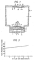
- FIG. 1 depicts a container constituting an ink cartridge body, indicated generally at reference numeral 1 is formed with a first wall 1a with an ink supply port 2 formed therein, into which an ink supply needle of a recording head (not shown) may be inserted.
- the space inside container 1 is separated into an ink chamber 4 and an ink supply chamber 5 by a membrane valve seat 3, described hereinafter.
- Membrane valve seat 3 is made of an elastic membrane, such as a rubber membrane, polymeric elastomer membrane or the like, having a resistance to ink, and formed with a membrane through hole 6 in a central portion thereof.
- Membrane valve seat 3 is placed on a step 7 formed in a lower portion of container 1.
- Membrane valve seat 3 is maintained in a stretched state by a valve assembly 9 which engages and holds the periphery of membrane valve seat 3 against step 7.
- valve body 8 is vertically movably inserted into a valve through hole 10 formed through valve assembly 9.
- Valve body 8 has a width that ensures the formation of a gap between valve assembly 9 and valve body 8 through which ink flows, and a length slightly larger than the thickness of valve assembly 9.
- valve body 8 In a normal state, when cartridge 1 is not connected to a recording head undergoing a printing operation, valve body 8 has its lower end placed in elastic contact with membrane valve seat 3 by a valve body support member 11 so as to close the membrane through hole 6 of membrane valve seat 3.
- the lower end of valve body 8 is formed with a curved periphery to form a better seal with membrane valve seat 3.
- Valve assembly 9 is formed with an ink passage 15 in the surface thereof facing away from ink supply port 2 and communicating to valve through hole 10 for directing ink thereto.
- Valve body support member 11 is arranged on and secured at its periphery to the surface of valve assembly 9 on the opposed side of valve assembly 9 to membrane valve seat 3, in a stretched state in order to maintain valve body 8 in elastic contact with membrane valve seat 3, as well as to prevent valve body 8 from lowering below a predetermined position.
- Valve body support member 11 is made of a similar material to that of membrane valve seat 3, and is formed with a support member through hole 12 therein forming ink passage 15. Also, valve body support member 11 supports a top portion 8a of valve body 8 adjacent but spaced from support member through hole 12.
- valve body 8 is formed with annular peripheral groove 8b for receiving the periphery of a mounting aperture 11a in valve support member 11 and a head 8a shaped both to be forced through mounting aperture 11a by elastic deformation thereof due to its rounded top end, and to retain the valve body on the valve body support membrane when mounted thereon.
- membrane valve seat 3, valve body support member 11, and valve body 8 are assembled with and fixed to valve assembly 9 prior to the final construction of container 1, and are incorporated into container 1 by placing the entire assembly on step 7 of container 1 at one time.
- Container 1 has its upper end closed by a lid member 13 having an atmosphere communicating hole 14 formed therethrough.
- lid member 13 On the side of lid member 13 facing the inside of ink chamber 4, lid member 13 is formed with a recess. 30 surrounding atmosphere communicating hole 14, a communicating port 32 positioned a predetermined distance away from recess 30, and a narrow groove 31 constituting a capillary channel for maintaining recess 30 and communicating port 32 in fluid communication.
- a flexible membrane 33 is arranged over recess 30 and groove 31 in such a loose state that flexible membrane 33 is maintained a small distance away from communicating hole 14 when lid member 13 is placed on container 1, while one wall of the capillary channel of groove 31 is defined by flexible membrane 33.
- ink supply port 2 When ink supply port 2 is penetrated by an ink supply needle of the recording head (not shown) carried on a carriage (the ink supply port being normally sealed by an ink impermeable closure (not shown) pierceable by the needle in a conventional manner), ink supply chamber 5 is placed in fluid communication via this ink supply needle with the recording head. In this state, flexible membrane 33 of lid member 13 is maintained in a hanging position away from lid member 13 so as to open atmosphere communication hole 14 because of gravity or other pressure difference. Thus, ink chamber 4 communicates with the atmosphere through open atmosphere communicating hole 14, recess 30, groove 31, and communicating port 32.
- ink in ink supply chamber 5 flows through ink supply port 2 into the recording head, whereby the pressure inside ink supply chamber 5 gradually decreases.
- membrane valve seat 3 receives pressure from ink chamber 4 and expands in the direction toward ink supply port 2, by virtue of its elasticity, in the form of an essentially spherical surface having a radius R.
- valve body 8 moves in conjunction with membrane valve seat 3 (FIG.
- ink contained in ink chamber 4 is prohibited from flowing into ink supply chamber 5 which in turn prevents the pressure inside ink supply chamber 5 from increasing excessively, while also preventing the pressure inside ink supply chamber 5 from decreasing excessively. In this manner, the pressure on the recording head is maintained at constant negative pressure with respect to the ink chamber 4.
- membrane valve seat 3 is further elastically expanded toward ink supply port 2.
- Valve body 8 is prevented from lowering below a predetermined position by valve body support member 11, so that valve body 8 is separated from membrane valve seat 3 by a very narrow gap 6a (FIG. 2B).
- ink in ink chamber 4 passes through support through hole 12, passage 15, valve through hole 10 and narrow gap 6a formed between valve body 8 and membrane valve seat 3, and flows through membrane through hole 6 into ink supply chamber 5.
- membrane valve seat 3 moves back toward valve body 8 by its elasticity and elastically contacts with valve body 8, whereby narrow gap 6a and membrane through hole 6 are closed by the lower surface of valve body 8. This prohibits ink from flowing from ink chamber 4 into ink supply chamber 5. As a result, the pressure at the ink supply port is maintained at a constant level irrespective of the amount of ink contained in ink chamber 4.
- membrane valve seat 3 Each time the pressure inside ink supply chamber 5 slightly decreases because of ink consumption during a printing operation, membrane valve seat 3 slightly expands toward ink supply port 2 to form a gap between membrane valve seat 3 and valve body 8, through which ink from ink chamber 4 flows into ink supply chamber 5. In this manner, membrane valve seat 3, made of an elastic membrane, is brought into contact with and separated from valve body 8 in accordance with the consumption of ink during printing.
- membrane valve seat 3 made of an elastic membrane, it is possible to remarkably reduce the difference in pressure between the time an ink supply procedure will begin and end, as well as to discharge all ink in ink chamber 4 to the recording head so that none of the ink will be wasted.
- membrane valve seat 3 moves toward ink chamber 4 which is open to the atmosphere. This prevents the pressure inside ink supply chamber 5 from increasing, thus maintaining appropriate negative pressure between ink chamber 4 and recording head irrespective of temperature rise or pressure increase. It is therefore possible to prevent ink from leaking from the recording head due to an increase in pressure.
- membrane valve seat 3 is formed of a rubber membrane having a thickness of 0.04 mm and an effective diameter, i.e., an elastically deformable region of 20 mm.
- a lower limit position of valve body 8 is designed such that the radius R of the spherical surface is 26 mm immediately before ink flows out, i.e., in a critical state with valve body 8.
- FIG. 3 is a graph which depicts the change in fluid pressure value of the ink cartridge. It can be understood from FIG. 3 that even if a large amount of ink, for example, five grams per minute of ink, is supplied, the increase in fluid pressure value is small. Thus, ink can be smoothly supplied to the recording head even if a large amount of ink is consumed by the recording head without imparting excessive negative pressure on the recording head.
- ink chamber 4 During the manufacturing and ink filling process, a negative pressure is applied to ink chamber 4 to exhaust air from cartridge 1.
- ink supply port 2 being closed by a filling seal 16
- ink chamber 4 initially achieves a lower pressure than ink supply chamber 5.
- valve body 8 moves toward ink chamber 4 against the elastic force of valve body support member 11 to form a filling gap 12a between membrane valve seat 3 and valve body 8, so that all air can be exhausted from the entire cartridge 1 including ink chamber 4 and ink supply chamber 5, irrespective of the existence of membrane valve seat 3 and valve body 8. This permits the entire cartridge 1, including ink supply chamber 5, to be filled with ink.
- valve body 8 is provided with a flat positioning piece 35 fixed thereto on the side thereof facing valve body support member 11, in the region of valve through hole 10, which abuts the upper peripheral surface of valve body 8 when the lower surface of valve body 8 is brought into contact with membrane valve seat 3.
- positioning piece 35 is maintained in contact with the upper surface of valve assembly 9 and the periphery of valve body 8, and valve body 8 is supported by valve assembly 9 to maintain its posture as vertical as possible.
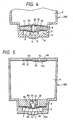
- FIG. 5 depicts an ink cartridge 300, like elements being designated by like reference numerals.
- a valve body 20 is inserted into a valve body accommodating chamber 9a formed in valve assembly 9' with spring 21 positioned to urge valve body 20 toward ink supply port 2.
- a lower limit position of valve body 20 is defined by a laterally outwardly extending positioning piece 36 formed on the upper end of valve body 20 abutting a laterally inwardly extending protrusion 9b formed in a lower portion of valve body accommodating chamber 9a. Also, as is shown in FIG.
- ink chamber 4 is selectively maintained in fluid communication with ink supply chamber 5 via through holes 22 and 23, through hole 22 communicating directly between ink chamber 4 and valve body accommodating chamber 9a, which through hole 23 communicates directly between ink chamber 4 and the space between membrane valve seat 3 and has a laterally extending surface groove 23a formed on the side of valve assembly 9' facing said membrane valve seat 3 extending between through hole 23 and valve body accommodating chamber 9a.
- membrane valve seat 3 in response to decreased pressure inside ink supply chamber 5, receives pressure from ink chamber 4 and expands toward supply port 2, by virtue of its elasticity, in the form of an essentially spherical surface having a radius R.
- valve body 20 moves in conjunction with membrane valve seat 3 by the resilient force of spring 21, and positioning piece 36 abuts protrusion 9b to maintain valve body 20 in a vertical posture (FIG. 6A)
- ink is prohibited from flowing from ink chamber 4 into ink supply chamber 5 while preventing the pressure inside ink supply chamber 5 from decreasing excessively.
- membrane valve seat 3 abuts valve body 20 irrespective of any vibrations or swinging motion of the cartridge due to the movement of the carriage, so that ink pressure on the recording head is maintained at constant negative pressure with respect to ink chamber 4.
- membrane valve seat 3 is further expanded toward ink supply port 2.
- Valve body 20 is prevented from lowering below a predetermined position by protrusion 9b of valve accommodating chamber 9a, so that valve body 8 is separated from membrane valve seat 3 by very narrow gap 6a (FIG. 6B).
- ink in ink chamber 4 passes through narrow gap 6a formed between valve body 20 and membrane valve seat 3 and flows through membrane through hole 6 into ink supply chamber 5.
- membrane valve seat 3 moves back toward valve body 20 by its elasticity and elastically contacts with valve body 20, whereby narrow gap 6a and membrane through hole 6 are closed by the lower surface of valve body 20. This prohibits ink from flowing from ink chamber 4 into ink supply chamber 5. As a result, the pressure at ink supply port 2 is maintained at a constant level irrespective of the amount of ink contained in the ink chamber 4.
- ink chamber 4 During the manufacturing and ink filling process, a negative pressure is applied to ink chamber 4 to exhaust air from cartridge 300. With ink supply port 2 being closed by filling seal 16, ink chamber 4 achieves a lower pressure than ink supply chamber 5.
- valve body 20 moves toward ink chamber 4 against force of spring 21 to form a filling gap 12a between membrane valve seat 3 and valve body 20, so that all air can be exhausted from the entire cartridge 300, irrespective of the existence of membrane valve seat 3 and valve body 20. This permits the entire cartridge 300 including ink supply chamber 5 to be filled with ink.
- valve assembly 9' an elastic member (spring 21) for bringing valve body 20 into contact with membrane valve seat 3 is incorporated in valve assembly 9'.
- an ink cartridge body 400 may be formed with a valve body 37, as shown in FIG. 7, which may be formed in a mushroom shape, such that a cap portion 37a functions as a positioning piece and as a stopper, and a spring 38, mounted at its periphery to the top surface of valve assembly 9", may be used to urge the top of valve body 37 toward membrane valve seat 3. Since valve body 37 and spring 38 can be mounted from the outside of valve assembly 9", the assembling work of the ink tank cartridge can be simplified.
- a through hole 9c is formed in valve assembly 9" communicating between ink chamber 4 and the space between the lower surface of valve assembly 9" and membrane valve seat 3.
- FIG. 8 depicts an ink cartridge 500 constructed in accordance with a fifth illustrative example of the invention, like elements being designated by like reference numerals. While in the foregoing illustrative example, the spring is arranged above the valve body, it is apparent that similar effects can be produced when ink cartridge 500 is separated into an ink chamber 42 and an ink supply chamber 43 by a partition 41 formed with a partition through hole 41a.
- Ink supply chamber 43 houses a membrane valve seat 44 and a valve body 46 comprising an elongated portion 46b extending through a membrane through hole 45 and head portion having a spherically formed lower surface 46a for sealing membrane through hole 45 formed through membrane valve seat 44.
- Elongated portion 46b extends from and perpendicular to lower surface 46a and penetrating membrane through hole 45 of membrane valve seat 44. Elongated portion 46b extends through and is supported on a spring 47 which always urges elongated portion 46b, and therefore valve body 46, in the direction of an ink supply port 49 and a guide hole 48, which receives the lower end of support member 46b to position valve body 46 in a vertical posture formed in a wall of the cartridge as shown in FIG. 8.
- Guide hole 48 is defined by an upwardly projecting annular wall 43a formed in a bottom wall 49a of ink cartridge 500.
- valve body 46 is always urged toward wall 49a, in which ink supply port 49 is formed, by spring 47 to maintain a stable posture, irrespective of any force generated by ink, ink can be stably supplied to the recording head irrespective of any vibrations or swinging motion of ink in cartridge 500 due to the movement of the carriage.
- membrane valve seat 44 moves toward ink supply port 49, thereby maintaining the pressure below valve seat 44.
- elongated portion 46b engages the bottom of guide hole 48, the movement of valve body 46 is stopped. Thereafter, any additional consumption of ink moves membrane valve seat 44 away from lower surface 46a of support member 46, thereby exposing a membrane through hole 45, and allowing ink to pass therethrough.
- FIG. 9 depicts ink cartridge 600 constructed in accordance with a sixth illustrative example of the invention, like elements being designated by like reference numerals.
- a level stabilizing membrane 50 is made of a soft porous membrane or lattice membrane which can move in conjunction with membrane valve seat 3 is provided.
- a porous member through hole 51 is formed through a region opposite valve body 8 of stabilizing membrane 50, and a lower end portion of valve body 8 is fit into porous member through hole 51.
- Stabilizing membrane 50 has its periphery secured to valve assembly 9 and a central portion thereof secured to valve body 8.
- membrane valve seat 3 separates from valve body 8 so that ink in ink chamber 4 flows through porous member through hole 51 of level stabilizing membrane 50 into ink supply chamber 5.
- the ink in ink chamber 4 may violently swing near valve body 8 due to the movement of the carriage.
- the ink passes through membrane through hole 6 of membrane valve seat 3 after fluctuations in pressure of the ink have been suppressed by level stabilizing membrane 50 as much as possible, the ink pressure on the recording head is maintained at a constant level irrespective of the amount of ink remaining in ink chamber 4.
- an elastic member (valve body support member 11) is used to elastically maintain contact between the valve body 8 and membrane valve seat 3, the elastic member for elastically contacting valve body 8 with membrane valve seat 3 may be unnecessary if the elastic force of membrane valve seat -3 is actively utilized.
- FIG. 10 depicts an ink cartridge 700 constructed in accordance with a seventh illustrative example of the invention, like elements being designed by like reference numerals.
- This seventh illustrative example does not require an elastic member for elastically urging a valve body to maintain contact with a membrane valve seat.
- a membrane valve seat 24 is formed with a membrane through hole 25 formed therein in a region opposing a valve body 28, hereinafter described, and has its periphery secured by a valve assembly 27.
- Valve body 28 is unmovably fixed to valve assembly 27 in a position perpendicular thereto.
- Ink chamber 4 is selectively maintained in fluid communication with ink supply chamber 5 via a communicating hole 29 in the form of a radial slit extending from valve body 28.
- membrane valve seat 24 When a pressure difference between ink chamber 4 and ink supply chamber 5 is equal to or less than a predetermined value, membrane valve seat 24, through its own elasticity, brings membrane through hole 25 into contact with valve body 28 to stop the outflow of ink from ink chamber 4 to ink supply chamber 5.
- membrane valve seat 24 extends toward ink supply port 2 in the form of a spherical surface, whereby membrane through hole 25 is removed from contact with valve body 28, and accordingly ink flows from ink chamber 4 into ink supply chamber 5 via membrane through hole 25.
- membrane valve seat 24 elastically contacts with valve body 28, against the pressure difference between ink chamber 4 and ink supply chamber 5, to stop the outflow of ink from ink chamber 4 to ink supply chamber 5.
- FIG. 11 depicts an ink cartridge constructed in accordance with an eighth illustrative example of the invention, like elements being designated by like reference numerals.
- the ink cartridge of this eighth illustrative example prevents air from entering a recording head at the time the recording head has depleted all of the ink in the ink cartridge.
- a downwardly tapered conical valve seat 54 is formed in a connecting region between an ink supply port 52 and an ink supply chamber 53 .
- a spherical floating valve 55 which floats by a floating force produced by the buoyancy of spherical floating valve 55, is accommodated in conical valve seat 54.
- a valve retention plate 56 made of an ink transmissible material such as a screen, to complete a shielding valve.
- a membrane valve seat 57 is also arranged in selectable contact with a valve body 58 for controlling the flow of ink thereto from an ink chamber (not shown).
- floating valve 55 When the ink cartridge is mounted on the recording head, floating valve 55 floats upward and is retained against valve retention plate 56 by a floating force to open ink supply port 52 through which ink is supplied to the recording head. As ink in the cartridge is consumed during printing operations, the level of ink in the cartridge is reduced in the vicinity of ink supply port 52. Floating valve 55 looses its floating force because of the absence of ink, and therefore comes into contact with valve seat 54 to close ink supply port 52 (as indicated by the broken line in FIG. 11). Even if printing is continued with the almost exhausted cartridge, the closed ink supply port 52 prohibits air from entering the recording head, thus preventing defective printing.
- an ink cartridge once mounted on a recording head, is not removed until ink contained in the ink chamber is depleted.
- the ink cartridge may be removed from the recording head by an erroneous manipulation. If a once mounted cartridge is removed from the racording head, ink supply port 52 is open to the atmosphere and may allow air to enter the ink supply chamber and the ink chamber, which may adversely affect the flow of ink during the recording operation.
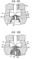
- FIGS. 12A and 12B depict an ink tank cartridge constructed in accordance with an embodiment of the present invention, like elements being designated by like reference numerals.
- the ink cartridge of this embodiment prevents air from entering the cartridge if the ink cartridge is removed before it is depleted.
- a telescopical valve body 60 is arranged in an ink supply port 61, and is formed with an ink supply needle fitting hole 62 in its lower portion into which an ink supply needle 70 may be removably fitted.
- Valve body 60 is also formed with a communicating hole 64 for connecting an ink supply chamber 63 with ink supply needle fitting hole 62 when valve body 60 moves to an upward limited position.
- valve body 60 which is formed with a radially extending, elastic periphery 60a, is maintained in elastic contact with a bottom surface 63a of ink supply chamber 63 by its elasticity to reliably prevent the outflow of ink from ink supply chamber 63.
- valve body 60 When ink supply needle 70 is inserted into fitting hole 62, valve body 60 is separated from bottom surface 63a of ink supply chamber 63 and extends to the upward limited position, while communicating hole 64 is exposed to ink supply chamber 63 (FIG. 12B). This causes ink supply chamber 63 to be placed in fluid communication with an ink passage 70a of ink supply needle 70 through communicating hole 64, and a needle communicating hole 70b, whereby ink in ink supply chamber 63 flows into ink supply needle 70 and is consequently supplied to the recording head. When the ink cartridge mounted on the recording head is removed, valve body 60 moves toward the bottom 63A of FIG. 12A to close ink supply port 61 and hence ink supply chamber 63. This prevents the outflow of ink from ink supply chamber 63 as well as the entrance of air into ink supply chamber 63.
- a container formed with an ink supply port in one of its walls is separated by a membrane valve seat made of an elastic thin membrane and formed with a through hole in the central portion thereof.
- An ink chamber is formed in the portion of the cartridge not adjacent the ink supply port, and an ink supply chamber is formed in the portion of the cartridge adjacent the ink supply port, and a valve body is positioned in opposition to the through hole.
- the membrane valve seat receives a pressure difference over a large area thereof because of the consumption of ink and allows ink to flow from the ink chamber in response to a small amount of consumed ink.
- the recording head can be supplied with ink without imparting excessive negative pressure on the recording head, and ink in the ink chamber can be discharged to the recording head without waste.
- the membrane valve body displaces toward the ink chamber to release the pressure increased by the pressure rise inside the ink supply chamber communicating with the recording head to the ink chamber. It is therefore possible to prevent ink from leaking when the printer is not in use.
- negative pressure suitable for printing is maintained between the recording head and the ink cartridge to ensure stable printing.
- the valve function can be reliably performed irrespective of any swinging motion or vibrations of ink in the ink chamber caused by the movement of the carriage, thus making it possible to maintain a pressure difference between the ink cartridge and the recording head irrespective of the movement of the carriage to achieve an improvement in printing quality.
Description
- The present invention relates to an ink cartridge for an ink jet recording apparatus and an ink jet recording apparatus comprising such ink cartridge.
- An ink jet recording apparatus such as an ink jet printer comprises an ink jet type recording head carried on a carriage in which pressure is applied to a pressure generating chamber. This chamber is maintained in fluid communication with a common ink tank on one side of the chamber and a nozzle opening on an other. Ink droplets are discharged from the nozzle opening upon the generation of pressure in the chamber. An ink cartridge comprising either the common ink tank or the common ink tank and a plurality of chambers and nozzle openings may be carried on the carriage for supplying the recording head with ink. This ink cartridge is constructed so that ink droplets are discharged onto a recording medium in response to printing data as the carriage is reciprocally moved.
- Since the nozzle opening of the recording head is located at a position lower than the ink level in the ink cartridge, fluid pressure of the ink acts on the nozzle opening. A porous material is generally contained in the ink cartridge so that surface tension caused by the porous material allows the pressure inside the ink cartridge to be slightly lower than that at the nozzle opening in order to prevent ink from oozing out from the nozzle opening.
- However, as ink is gradually consumed during printing operations and a smaller amount of ink remains absorbed in the porous material, the surface tension caused by the porous material becomes larger and makes it difficult to supply ink to the recording head. Thus, all ink contained in the cartridge will not be completely consumed.
- Also, because of the porous material contained in the ink cartridge, the amount of ink stored in the ink cartridge is less than the volume of the ink cartridge by the actual total volume of the porous material. To compensate for the decreased amount of ink in a cartridge employing porous material, a larger ink cartridge is required than would be if the porous material were not employed in order to hold the same amount of ink.
- To solve the problem mentioned above, an ink cartridge for an ink jet recording head, for example, as shown in United States Patent No. 4,677,447 (based upon JP-A-62-231759), has been proposed. This patent shows an ink tank that is separated into two chambers by a wall formed with a through hole in a lower portion thereof. Ink is provided to the recording head from the first chamber. An umbrella check valve is movably arranged in the through hole. When the ink pressure on the ink head is decreased by expulsion of ink from the chamber, the umbrella check valve is opened to discharge the ink from the into to the cavity, and it is then supplied to the recording head from the first chamber into the second chamber, and it is then supplied to the recording head from the second chamber cavity.
- According to the above-mentioned ink cartridge, a porous material need not be contained in the cartridge, so that a larger amount of ink can be substantially stored in the ink cartridge. However, use of the umbrella check valve raises another problem, since its offset amount is too large to finely adjust the amount of ink to be supplied to the recording head. Thus, fluctuations in the amount of ink supplied are caused and the printing quality is degraded.
- In addition, since the ink in the first chamber is completely blocked from the recording head when the umbrella check valve is closed, if some change in environmental factors or temperature causes the volume of ink in the second chamber to increase as little as two to five percent, the pressure in the first chamber could increase and break the seal on a connection port which couples the ink cartridge to the recording head. The ink could then leak from the broken seal. Further, when the cartridge is mounted on the recording head, this increased pressure acts on the recording head whereby negative pressure cannot be maintained between the recording head and the ink tank, and thus ink could leak from the recording head.
- Furthermore, the umbrella check valve is maintained in a closed state with a pressure difference of approximately 50 mmAq in order to ensure a stable supply of ink to the recording head. However, since this valve closing force is small, the umbrella check valve may open in response to a swinging motion of ink in the ink tank due to the movement of the carriage resulting in temporary pressure differences against the valve from the movement. Thus, stable printing may not be provided.
- Additionally, if air enters a recording head while ink is being supplied thereto, the pressure for discharging ink droplets may be absorbed by the air bubble occurring within an ink passage of the recording head. Thus, defective printing may arise when the ink cartridge is exhausted. This problem may also arise if an ink cartridge is removed from a recording head if the ink is not depleted.
- Accordingly, it is desirable to provide an ink cartridge which is capable of reliably supplying a recording head with ink in response to a minute pressure difference between the recording head and the ink cartridge, while maintaining negative pressure suitable for printing between the recording head and the ink cartridge, without being influenced by any swinging motion of ink contained therein due to the movement of a carriage upon which the recording head is mounted, and is also capable of preventing ink from leaking from an ink supply port of the cartridge leading to the recording head, or leaking from the recording head, due to temperature or other atmospheric changes.
- Additionally, it is desirable to provide an ink cartridge which can prevent air from being drawn into the recording head at the time ink in the ink cartridge is exhausted, or if the ink cartridge is removed before all of the ink is depleted.
- From US 5,343,226 there is known an ink cartridge for an ink jet recording apparatus in which a valve is provided for preventing air from being drawn into the recording head and for preventing depletion of ink when the ink cartridge is removed.
- The conventional ink cartridge comprises a sealing valve retained in an ink supply port wherein the sealing valve is displaceable between a first position at which the sealing valve is biased to close the ink supply port, and a second position at which the ink supply port is placed in fluid communication with the interior of a fluid container to permit flow of ink from the interior of the container.
- It is an object of the present invention to provide an ink cartridge of the type illustrated above having improved sealing capabilities.
- This object is solved by providing an ink cartridge comprising the features defined in appended claim 1.
- Preferred embodiments of the invention are defined in the dependent claims.
- Other aspects and advantages of the invention will in part be obvious and will in part be apparent from the specifications and drawings.
- Additionally, the invention accordingly comprises the features of construction, combinations of elements, and arrangements of parts which will be exemplified in the constructions hereinafter set forth, and the scope of the invention will be indicated in the claims.
- For a fuller understanding of the invention, reference is made to the following description taken in conjunction with the accompanying drawings, in which:
- FIG. 1 is a cross-sectional view of a comparable ink tank cartridge (not forming an embodiment of the invention);
- FIGS. 2A and 2B respectively are fragmentary cross-sectional views of the ink tank cartridge of FIG. 1 showing how the membrane valve seat and the valve body operate when the ink cartridge is mounted on a recording head;
- FIG. 2C is a cross-sectional view of the ink tank cartridge of FIG. 1 showing the valve body when the ink cartridge is supplied with ink;
- FIG. 3 is a graph representing the relationship between a discharging amount of ink and the fluid pressure value of the ink cartridge of FIG. 1;
- FIG. 4 is a fragmentary cross-sectional view of a comparable ink tank cartridge (not forming an embodiment of the invention) showing the ink supply chamber and its surroundings;
- FIG. 5 is a cross-sectional view of a comparable ink tank cartridge (not forming an embodiment of the invention);
- FIGS. 6A and 6B respectively are fragmentary cross-sectional views of the ink tank cartridge of FIG. 5 showing how the membrane valve seat and the valve body operate when the ink cartridge is mounted on a recording head;
- FIG. 6C is also a cross-sectional view of the ink tank cartridge of FIG. 5 showing the valve body when the ink cartridge is supplied with ink;
- FIG. 7 is a fragmentary cross-sectional view of a comparable ink tank cartridge (not forming an embodiment of the invention) showing the ink supply chamber and its surroundings;
- FIG. 8 is a fragmentary cross-sectional view of a comparable ink tank cartridge (not forming an embodiment of the invention) showing the ink supply chamber and its surroundings;
- FIG. 9 is a fragmentary cross-sectional view of a comparable ink tank cartridge (not forming an embodiment of the invention) showing the ink supply chamber and its surroundings;
- FIG. 10 is a fragmentary cross-sectional view of a comparable ink tank cartridge (not forming an embodiment of the invention) showing the ink supply chamber and its surroundings;
- FIG. 11 is a cross-sectional view showing an ink supply port of a comparable ink cartridge (not forming an embodiment of the invention); and
- FIGS. 12A and 12B are cross-sectional views showing an ink supply port of an ink cartridge constructed in accordance with an embodiment of the invention, FIG. 12A showing the ink supply port not mounted on a recording head and FIG. 12B showing the ink supply port mounted on a recording head.
- FIG. 13 is a schematic view showing an ink supply system, which is an essential part of the ink jet type recording apparatus according to the embodiments of the present invention.
-
- Fig. 13 is a schematic view showing an ink supply system of an ink-jet type recording apparatus to which the present invention can be applied.
- A
print heat unit 101 of an ink-jet type is connected to anink tank 103 through a connectingmember 102. Ink is supplied from theink tank 103 to theprint head unit 101 through ahollow needle 102a and anink supply passage 102b of the connectingmember 102, so that theprint head unit 101 emits ink droplets in accordance with print signals. - The apparatus shown in Fig. 13 also includes a
cap member 104 disposed at non-printing area, which cap member comes into abutment against the nozzle plate of theprint head unit 101 by a drive mechanism (not shown) for preventing the nozzle openings from drying. Thecap member 104 is connected through atube 108 to asuction pump 105 which is operated by acontrol device 106 to suck ink from theprint head unit 101 through thecap member 104. The apparatus shown in Fig. 13 is also provided with aneffluent tank 107 connected to an outlet port of thesuction pump 105 through atube 109. - The recording head may be of any structure such as described in European Patent Publication Nos. 581,531, 609,863, 584,823 and so on.
- FIG. 1, depicts a container constituting an ink cartridge body, indicated generally at reference numeral 1 is formed with a
first wall 1a with anink supply port 2 formed therein, into which an ink supply needle of a recording head (not shown) may be inserted. The space inside container 1 is separated into anink chamber 4 and anink supply chamber 5 by amembrane valve seat 3, described hereinafter.Membrane valve seat 3 is made of an elastic membrane, such as a rubber membrane, polymeric elastomer membrane or the like, having a resistance to ink, and formed with a membrane throughhole 6 in a central portion thereof.Membrane valve seat 3 is placed on a step 7 formed in a lower portion of container 1.Membrane valve seat 3 is maintained in a stretched state by avalve assembly 9 which engages and holds the periphery ofmembrane valve seat 3 against step 7. - A
valve body 8 is vertically movably inserted into a valve throughhole 10 formed throughvalve assembly 9.Valve body 8 has a width that ensures the formation of a gap betweenvalve assembly 9 andvalve body 8 through which ink flows, and a length slightly larger than the thickness ofvalve assembly 9. In a normal state, when cartridge 1 is not connected to a recording head undergoing a printing operation,valve body 8 has its lower end placed in elastic contact withmembrane valve seat 3 by a valvebody support member 11 so as to close the membrane throughhole 6 ofmembrane valve seat 3. The lower end ofvalve body 8 is formed with a curved periphery to form a better seal withmembrane valve seat 3.Valve assembly 9 is formed with anink passage 15 in the surface thereof facing away fromink supply port 2 and communicating to valve throughhole 10 for directing ink thereto. - Valve
body support member 11 is arranged on and secured at its periphery to the surface ofvalve assembly 9 on the opposed side ofvalve assembly 9 tomembrane valve seat 3, in a stretched state in order to maintainvalve body 8 in elastic contact withmembrane valve seat 3, as well as to preventvalve body 8 from lowering below a predetermined position. Valvebody support member 11 is made of a similar material to that ofmembrane valve seat 3, and is formed with a support member throughhole 12 therein formingink passage 15. Also, valvebody support member 11 supports atop portion 8a ofvalve body 8 adjacent but spaced from support member throughhole 12. In this example, the upper end ofvalve body 8 is formed with annularperipheral groove 8b for receiving the periphery of a mountingaperture 11a invalve support member 11 and ahead 8a shaped both to be forced through mountingaperture 11a by elastic deformation thereof due to its rounded top end, and to retain the valve body on the valve body support membrane when mounted thereon. - Preferably,
membrane valve seat 3, valvebody support member 11, andvalve body 8 are assembled with and fixed tovalve assembly 9 prior to the final construction of container 1, and are incorporated into container 1 by placing the entire assembly on step 7 of container 1 at one time. - Container 1 has its upper end closed by a
lid member 13 having anatmosphere communicating hole 14 formed therethrough. On the side oflid member 13 facing the inside ofink chamber 4,lid member 13 is formed with a recess. 30 surroundingatmosphere communicating hole 14, a communicatingport 32 positioned a predetermined distance away fromrecess 30, and anarrow groove 31 constituting a capillary channel for maintainingrecess 30 and communicatingport 32 in fluid communication. Aflexible membrane 33 is arranged overrecess 30 andgroove 31 in such a loose state thatflexible membrane 33 is maintained a small distance away from communicatinghole 14 whenlid member 13 is placed on container 1, while one wall of the capillary channel ofgroove 31 is defined byflexible membrane 33. - In this example, if container 1 is positioned (for example, tilted or turned upside down) to bring ink in
ink chamber 4 into contact withlid member 13,flexible membrane 33 receives the pressure of the ink and is moved towardslid member 13.Flexible membrane 33 then comes into contact with aprotrusion 14a defined byrecess 30 aroundatmosphere communicating hole 14, so thatatmosphere communicating hole 14 is closed to prevent the ink from leaking therethrough. - When
ink supply port 2 is penetrated by an ink supply needle of the recording head (not shown) carried on a carriage (the ink supply port being normally sealed by an ink impermeable closure (not shown) pierceable by the needle in a conventional manner),ink supply chamber 5 is placed in fluid communication via this ink supply needle with the recording head. In this state,flexible membrane 33 oflid member 13 is maintained in a hanging position away fromlid member 13 so as to openatmosphere communication hole 14 because of gravity or other pressure difference. Thus,ink chamber 4 communicates with the atmosphere through openatmosphere communicating hole 14,recess 30,groove 31, and communicatingport 32. - As is shown in FIGS. 2A, 2B and 2C, in the cartridge constructed in this manner, when printing is started and the recording head discharges ink droplets onto a recording medium or the like, ink in
ink supply chamber 5 flows throughink supply port 2 into the recording head, whereby the pressure insideink supply chamber 5 gradually decreases. In response to the decreased pressure insideink supply chamber 5,membrane valve seat 3 receives pressure fromink chamber 4 and expands in the direction towardink supply port 2, by virtue of its elasticity, in the form of an essentially spherical surface having a radius R. At this time, sincevalve body 8 moves in conjunction with membrane valve seat 3 (FIG. 2A), ink contained inink chamber 4 is prohibited from flowing intoink supply chamber 5 which in turn prevents the pressure insideink supply chamber 5 from increasing excessively, while also preventing the pressure insideink supply chamber 5 from decreasing excessively. In this manner, the pressure on the recording head is maintained at constant negative pressure with respect to theink chamber 4. - As more ink is consumed by the recording head during a printing operation,
membrane valve seat 3 is further elastically expanded towardink supply port 2.Valve body 8 is prevented from lowering below a predetermined position by valvebody support member 11, so thatvalve body 8 is separated frommembrane valve seat 3 by a verynarrow gap 6a (FIG. 2B). In this state, ink inink chamber 4 passes through support throughhole 12,passage 15, valve throughhole 10 andnarrow gap 6a formed betweenvalve body 8 andmembrane valve seat 3, and flows through membrane throughhole 6 intoink supply chamber 5. - When the inflow of the ink causes the pressure inside
ink supply chamber 5 to slightly increase,membrane valve seat 3 moves back towardvalve body 8 by its elasticity and elastically contacts withvalve body 8, wherebynarrow gap 6a and membrane throughhole 6 are closed by the lower surface ofvalve body 8. This prohibits ink from flowing fromink chamber 4 intoink supply chamber 5. As a result, the pressure at the ink supply port is maintained at a constant level irrespective of the amount of ink contained inink chamber 4. - Each time the pressure inside
ink supply chamber 5 slightly decreases because of ink consumption during a printing operation,membrane valve seat 3 slightly expands towardink supply port 2 to form a gap betweenmembrane valve seat 3 andvalve body 8, through which ink fromink chamber 4 flows intoink supply chamber 5. In this manner,membrane valve seat 3, made of an elastic membrane, is brought into contact with and separated fromvalve body 8 in accordance with the consumption of ink during printing. Thus, by setting the elasticity ofmembrane valve seat 3 at an appropriate predetermined magnitude, it is possible to remarkably reduce the difference in pressure between the time an ink supply procedure will begin and end, as well as to discharge all ink inink chamber 4 to the recording head so that none of the ink will be wasted. - If the ambient temperature rises while printing is not being performed, the pressure inside
ink supply chamber 5 will increase. This increase in pressure may also be caused by changes in a number of other environmental factors. In response to this increased pressure,membrane valve seat 3 moves towardink chamber 4 which is open to the atmosphere. This prevents the pressure insideink supply chamber 5 from increasing, thus maintaining appropriate negative pressure betweenink chamber 4 and recording head irrespective of temperature rise or pressure increase. It is therefore possible to prevent ink from leaking from the recording head due to an increase in pressure. - In an illustrative example,
membrane valve seat 3 is formed of a rubber membrane having a thickness of 0.04 mm and an effective diameter, i.e., an elastically deformable region of 20 mm. A lower limit position ofvalve body 8 is designed such that the radius R of the spherical surface is 26 mm immediately before ink flows out, i.e., in a critical state withvalve body 8. Reference is now made to FIG. 3, which is a graph which depicts the change in fluid pressure value of the ink cartridge. It can be understood from FIG. 3 that even if a large amount of ink, for example, five grams per minute of ink, is supplied, the increase in fluid pressure value is small. Thus, ink can be smoothly supplied to the recording head even if a large amount of ink is consumed by the recording head without imparting excessive negative pressure on the recording head. - During the manufacturing and ink filling process, a negative pressure is applied to
ink chamber 4 to exhaust air from cartridge 1. Withink supply port 2 being closed by a fillingseal 16,ink chamber 4 initially achieves a lower pressure thanink supply chamber 5. Thus, as shown in FIG. 2C,valve body 8 moves towardink chamber 4 against the elastic force of valvebody support member 11 to form afilling gap 12a betweenmembrane valve seat 3 andvalve body 8, so that all air can be exhausted from the entire cartridge 1 includingink chamber 4 andink supply chamber 5, irrespective of the existence ofmembrane valve seat 3 andvalve body 8. This permits the entire cartridge 1, includingink supply chamber 5, to be filled with ink. - Reference is now made to FIG. 4 which depicts an
ink cartridge 200, like elements being designated by like reference numerals. In this illustrative example,valve body 8 is provided with aflat positioning piece 35 fixed thereto on the side thereof facing valvebody support member 11, in the region of valve throughhole 10, which abuts the upper peripheral surface ofvalve body 8 when the lower surface ofvalve body 8 is brought into contact withmembrane valve seat 3. Whenvalve body 8 abutsmembrane valve seat 3,positioning piece 35 is maintained in contact with the upper surface ofvalve assembly 9 and the periphery ofvalve body 8, andvalve body 8 is supported byvalve assembly 9 to maintain its posture as vertical as possible. Thus, membrane throughhole 6 ofmembrane valve seat 3 can be reliably closed byvalve body 8 even ifcartridge 200 suffers from vibrations due to the movement of the carriage or the like. - Reference is now made to FIG. 5 which depicts an
ink cartridge 300, like elements being designated by like reference numerals. In this illustrative example avalve body 20 is inserted into a valvebody accommodating chamber 9a formed in valve assembly 9' withspring 21 positioned to urgevalve body 20 towardink supply port 2. A lower limit position ofvalve body 20 is defined by a laterally outwardly extendingpositioning piece 36 formed on the upper end ofvalve body 20 abutting a laterally inwardly extendingprotrusion 9b formed in a lower portion of valvebody accommodating chamber 9a. Also, as is shown in FIG. 5,ink chamber 4 is selectively maintained in fluid communication withink supply chamber 5 via throughholes hole 22 communicating directly betweenink chamber 4 and valvebody accommodating chamber 9a, which throughhole 23 communicates directly betweenink chamber 4 and the space betweenmembrane valve seat 3 and has a laterally extendingsurface groove 23a formed on the side of valve assembly 9' facing saidmembrane valve seat 3 extending between throughhole 23 and valvebody accommodating chamber 9a. - In this third illustrative example, as is shown in FIGS. 6A, 6B and 6C,
membrane valve seat 3, in response to decreased pressure insideink supply chamber 5, receives pressure fromink chamber 4 and expands towardsupply port 2, by virtue of its elasticity, in the form of an essentially spherical surface having a radius R. Thus, sincevalve body 20 moves in conjunction withmembrane valve seat 3 by the resilient force ofspring 21, andpositioning piece 36 abutsprotrusion 9b to maintainvalve body 20 in a vertical posture (FIG. 6A), ink is prohibited from flowing fromink chamber 4 intoink supply chamber 5 while preventing the pressure insideink supply chamber 5 from decreasing excessively. In this manner,membrane valve seat 3 abutsvalve body 20 irrespective of any vibrations or swinging motion of the cartridge due to the movement of the carriage, so that ink pressure on the recording head is maintained at constant negative pressure with respect toink chamber 4. - As more ink is consumed by the recording head during a printing operation,
membrane valve seat 3 is further expanded towardink supply port 2.Valve body 20 is prevented from lowering below a predetermined position byprotrusion 9b ofvalve accommodating chamber 9a, so thatvalve body 8 is separated frommembrane valve seat 3 by verynarrow gap 6a (FIG. 6B). In this state, ink inink chamber 4 passes throughnarrow gap 6a formed betweenvalve body 20 andmembrane valve seat 3 and flows through membrane throughhole 6 intoink supply chamber 5. - When the inflow of the ink causes the pressure inside
ink supply chamber 5 to slightly increase,membrane valve seat 3 moves back towardvalve body 20 by its elasticity and elastically contacts withvalve body 20, wherebynarrow gap 6a and membrane throughhole 6 are closed by the lower surface ofvalve body 20. This prohibits ink from flowing fromink chamber 4 intoink supply chamber 5. As a result, the pressure atink supply port 2 is maintained at a constant level irrespective of the amount of ink contained in theink chamber 4. - During the manufacturing and ink filling process, a negative pressure is applied to
ink chamber 4 to exhaust air fromcartridge 300. Withink supply port 2 being closed by fillingseal 16,ink chamber 4 achieves a lower pressure thanink supply chamber 5. Thus, as shown in FIG. 6C,valve body 20 moves towardink chamber 4 against force ofspring 21 to form afilling gap 12a betweenmembrane valve seat 3 andvalve body 20, so that all air can be exhausted from theentire cartridge 300, irrespective of the existence ofmembrane valve seat 3 andvalve body 20. This permits theentire cartridge 300 includingink supply chamber 5 to be filled with ink. - In the foregoing third illustrative example, an elastic member (spring 21) for bringing
valve body 20 into contact withmembrane valve seat 3 is incorporated in valve assembly 9'. Alternatively, in a fourth illustrative example, like elements being designated by like reference numerals, anink cartridge body 400 may be formed with avalve body 37, as shown in FIG. 7, which may be formed in a mushroom shape, such that acap portion 37a functions as a positioning piece and as a stopper, and aspring 38, mounted at its periphery to the top surface ofvalve assembly 9", may be used to urge the top ofvalve body 37 towardmembrane valve seat 3. Sincevalve body 37 andspring 38 can be mounted from the outside ofvalve assembly 9", the assembling work of the ink tank cartridge can be simplified. A throughhole 9c is formed invalve assembly 9" communicating betweenink chamber 4 and the space between the lower surface ofvalve assembly 9" andmembrane valve seat 3. - Reference is now made to FIG. 8 which depicts an
ink cartridge 500 constructed in accordance with a fifth illustrative example of the invention, like elements being designated by like reference numerals. While in the foregoing illustrative example, the spring is arranged above the valve body, it is apparent that similar effects can be produced whenink cartridge 500 is separated into anink chamber 42 and anink supply chamber 43 by apartition 41 formed with a partition throughhole 41a.Ink supply chamber 43 houses amembrane valve seat 44 and avalve body 46 comprising anelongated portion 46b extending through a membrane throughhole 45 and head portion having a spherically formedlower surface 46a for sealing membrane throughhole 45 formed throughmembrane valve seat 44.Elongated portion 46b extends from and perpendicular tolower surface 46a and penetrating membrane throughhole 45 ofmembrane valve seat 44.Elongated portion 46b extends through and is supported on aspring 47 which always urgeselongated portion 46b, and thereforevalve body 46, in the direction of anink supply port 49 and aguide hole 48, which receives the lower end ofsupport member 46b to positionvalve body 46 in a vertical posture formed in a wall of the cartridge as shown in FIG. 8.Guide hole 48 is defined by an upwardly projecting annular wall 43a formed in abottom wall 49a ofink cartridge 500. - According to this fifth illustrative example, since
valve body 46 is always urged towardwall 49a, in whichink supply port 49 is formed, byspring 47 to maintain a stable posture, irrespective of any force generated by ink, ink can be stably supplied to the recording head irrespective of any vibrations or swinging motion of ink incartridge 500 due to the movement of the carriage. In this illustrative example, similar to those described above, when the pressure belowmembrane valve seat 44 is decreased due to ink being consumed during printing,membrane valve seat 44 moves towardink supply port 49, thereby maintaining the pressure belowvalve seat 44. Whenelongated portion 46b engages the bottom ofguide hole 48, the movement ofvalve body 46 is stopped. Thereafter, any additional consumption of ink movesmembrane valve seat 44 away fromlower surface 46a ofsupport member 46, thereby exposing a membrane throughhole 45, and allowing ink to pass therethrough. - Reference is now made to FIG. 9 which depicts
ink cartridge 600 constructed in accordance with a sixth illustrative example of the invention, like elements being designated by like reference numerals. Alevel stabilizing membrane 50 is made of a soft porous membrane or lattice membrane which can move in conjunction withmembrane valve seat 3 is provided. A porous member throughhole 51 is formed through a regionopposite valve body 8 of stabilizingmembrane 50, and a lower end portion ofvalve body 8 is fit into porous member throughhole 51. Stabilizingmembrane 50 has its periphery secured tovalve assembly 9 and a central portion thereof secured tovalve body 8. - When the pressure inside
ink supply chamber 5 decreases as more ink is consumed during a printing operation,membrane valve seat 3 separates fromvalve body 8 so that ink inink chamber 4 flows through porous member throughhole 51 oflevel stabilizing membrane 50 intoink supply chamber 5. - After an additional amount of ink has been consumed during printing operations and the level of ink in
ink chamber 4 has been reduced to a level lower than the position ofvalve assembly 9, the ink inink chamber 4 may violently swing nearvalve body 8 due to the movement of the carriage. However, since the ink passes through membrane throughhole 6 ofmembrane valve seat 3 after fluctuations in pressure of the ink have been suppressed bylevel stabilizing membrane 50 as much as possible, the ink pressure on the recording head is maintained at a constant level irrespective of the amount of ink remaining inink chamber 4. - While in a number of the foregoing illustrative example, an elastic member (valve body support member 11) is used to elastically maintain contact between the
valve body 8 andmembrane valve seat 3, the elastic member for elastically contactingvalve body 8 withmembrane valve seat 3 may be unnecessary if the elastic force of membrane valve seat -3 is actively utilized. - Reference is now made to FIG. 10 which depicts an
ink cartridge 700 constructed in accordance with a seventh illustrative example of the invention, like elements being designed by like reference numerals. This seventh illustrative example does not require an elastic member for elastically urging a valve body to maintain contact with a membrane valve seat. As shown in FIG. 10, amembrane valve seat 24 is formed with a membrane throughhole 25 formed therein in a region opposing avalve body 28, hereinafter described, and has its periphery secured by avalve assembly 27.Valve body 28 is unmovably fixed tovalve assembly 27 in a position perpendicular thereto.Ink chamber 4 is selectively maintained in fluid communication withink supply chamber 5 via a communicatinghole 29 in the form of a radial slit extending fromvalve body 28. When a pressure difference betweenink chamber 4 andink supply chamber 5 is equal to or less than a predetermined value,membrane valve seat 24, through its own elasticity, brings membrane throughhole 25 into contact withvalve body 28 to stop the outflow of ink fromink chamber 4 toink supply chamber 5. - On the other hand, if the pressure inside
ink supply chamber 5 decreases,membrane valve seat 24 extends towardink supply port 2 in the form of a spherical surface, whereby membrane throughhole 25 is removed from contact withvalve body 28, and accordingly ink flows fromink chamber 4 intoink supply chamber 5 via membrane throughhole 25. After a sufficient amount of ink has been supplied toink supply chamber 5 to raise the pressure insideink supply chamber 5,membrane valve seat 24 elastically contacts withvalve body 28, against the pressure difference betweenink chamber 4 andink supply chamber 5, to stop the outflow of ink fromink chamber 4 toink supply chamber 5. - Reference is now made to FIG. 11 which depicts an ink cartridge constructed in accordance with an eighth illustrative example of the invention, like elements being designated by like reference numerals. The ink cartridge of this eighth illustrative example prevents air from entering a recording head at the time the recording head has depleted all of the ink in the ink cartridge. In a connecting region between an
ink supply port 52 and anink supply chamber 53, a downwardly taperedconical valve seat 54 is formed. A spherical floatingvalve 55, which floats by a floating force produced by the buoyancy of spherical floatingvalve 55, is accommodated inconical valve seat 54. Further, the upper end of theconical valve seat 54 is covered with avalve retention plate 56, made of an ink transmissible material such as a screen, to complete a shielding valve. In FIG. 11, amembrane valve seat 57 is also arranged in selectable contact with avalve body 58 for controlling the flow of ink thereto from an ink chamber (not shown). - When the ink cartridge is mounted on the recording head, floating
valve 55 floats upward and is retained againstvalve retention plate 56 by a floating force to openink supply port 52 through which ink is supplied to the recording head. As ink in the cartridge is consumed during printing operations, the level of ink in the cartridge is reduced in the vicinity ofink supply port 52. Floatingvalve 55 looses its floating force because of the absence of ink, and therefore comes into contact withvalve seat 54 to close ink supply port 52 (as indicated by the broken line in FIG. 11). Even if printing is continued with the almost exhausted cartridge, the closedink supply port 52 prohibits air from entering the recording head, thus preventing defective printing. - Generally, an ink cartridge, once mounted on a recording head, is not removed until ink contained in the ink chamber is depleted. However, the ink cartridge may be removed from the recording head by an erroneous manipulation. If a once mounted cartridge is removed from the racording head,
ink supply port 52 is open to the atmosphere and may allow air to enter the ink supply chamber and the ink chamber, which may adversely affect the flow of ink during the recording operation. - Reference is now made to FIGS. 12A and 12B which depict an ink tank cartridge constructed in accordance with an embodiment of the present invention, like elements being designated by like reference numerals. As shown in FIGS. 12A and 12B, the ink cartridge of this embodiment prevents air from entering the cartridge if the ink cartridge is removed before it is depleted. A
telescopical valve body 60 is arranged in anink supply port 61, and is formed with an ink supply needlefitting hole 62 in its lower portion into which anink supply needle 70 may be removably fitted.Valve body 60 is also formed with a communicatinghole 64 for connecting anink supply chamber 63 with ink supply needlefitting hole 62 whenvalve body 60 moves to an upward limited position. - In this embodiment, before insertion of
ink supply needle 70, as shown in FIG. 12A,valve body 60 which is formed with a radially extending,elastic periphery 60a, is maintained in elastic contact with abottom surface 63a ofink supply chamber 63 by its elasticity to reliably prevent the outflow of ink fromink supply chamber 63. - When
ink supply needle 70 is inserted intofitting hole 62,valve body 60 is separated frombottom surface 63a ofink supply chamber 63 and extends to the upward limited position, while communicatinghole 64 is exposed to ink supply chamber 63 (FIG. 12B). This causesink supply chamber 63 to be placed in fluid communication with anink passage 70a ofink supply needle 70 through communicatinghole 64, and aneedle communicating hole 70b, whereby ink inink supply chamber 63 flows intoink supply needle 70 and is consequently supplied to the recording head.
When the ink cartridge mounted on the recording head is removed,valve body 60 moves toward the bottom 63A of FIG. 12A to closeink supply port 61 and henceink supply chamber 63. This prevents the outflow of ink fromink supply chamber 63 as well as the entrance of air intoink supply chamber 63. - According to the illustrative examples as described above, a container formed with an ink supply port in one of its walls is separated by a membrane valve seat made of an elastic thin membrane and formed with a through hole in the central portion thereof. An ink chamber is formed in the portion of the cartridge not adjacent the ink supply port, and an ink supply chamber is formed in the portion of the cartridge adjacent the ink supply port, and a valve body is positioned in opposition to the through hole. The membrane valve seat receives a pressure difference over a large area thereof because of the consumption of ink and allows ink to flow from the ink chamber in response to a small amount of consumed ink. Thus, the recording head can be supplied with ink without imparting excessive negative pressure on the recording head, and ink in the ink chamber can be discharged to the recording head without waste. Moreover, if the ambient temperature rises greatly or other environmental factors cause the pressure to increase while printing is not being performed, the membrane valve body displaces toward the ink chamber to release the pressure increased by the pressure rise inside the ink supply chamber communicating with the recording head to the ink chamber. It is therefore possible to prevent ink from leaking when the printer is not in use. Also, when the ink cartridge is mounted on the recording head, negative pressure suitable for printing is maintained between the recording head and the ink cartridge to ensure stable printing.
- Further, since the elasticity of the membrane valve seat ensures an airtight seal between the membrane valve seat and the valve body, the valve function can be reliably performed irrespective of any swinging motion or vibrations of ink in the ink chamber caused by the movement of the carriage, thus making it possible to maintain a pressure difference between the ink cartridge and the recording head irrespective of the movement of the carriage to achieve an improvement in printing quality.
- It will thus be seen that the aspects set forth above, and those made apparent from the preceding description, are efficiently attained and, since certain changes may be made in the above constructions without departing from the scope of the invention, it is intended that all matter contained in the above description or shown in the accompanying drawings shall be interpreted as illustrative and not in a limiting sense.
- It is also to be understood that the following claims are intended to cover all of the generic and specific features of the invention herein described, and all statements of the scope of the invention which, as a matter of language, might be said to fall therebetween.
Claims (3)
- An ink cartridge for an ink jet recording apparatus, comprising:characterised in that said sealing valve is formed with a communicating hole (64) formed therein, wherein the communication hole (64) is able to be exposed into the interior of the container by an ink supply needle (70) that displaces the sealing valve from the first position to the second position during mounting of the ink cartridge on the ink jet recording apparatus.a container for storing ink having at least a first wall;an ink supply port formed through said first wall for supplying ink to the exterior of said container; anda sealing valve retained in said ink supply port, said sealing valve being displacable between a first position at which said sealing valve is biased to close said ink supply port and a second position at which said ink supply port is placed in fluid communication with the interior of said container to permit flow of ink from the interior of said container, said sealing valve being positioned to be displacable from said first position to said second position during mounting of said ink cartridge on said ink jet recording apparatus;
- The cartridge of claim 1, wherein the cartridge further comprises a valve body (58) and a membrane valve seat (57) arranged in selectable contact with said valve body (58) for controlling flow of ink from said container, and wherein said sealing valve is located downstream of said valve body (58) and said membrane valve seat (57)
- An ink jet recording apparatus comprising:a print head (101) for emitting ink droplets in accordance with print signals;an ink supply member engaging with said print head (101); andan ink cartridge according to claim 1 or 2 connected to said print head (101) through said ink supply member.
Priority Applications (4)
| Application Number | Priority Date | Filing Date | Title |
|---|---|---|---|
| EP20050025214 EP1640168A3 (en) | 1994-10-26 | 1995-10-26 | Ink cartridge for ink-jet printer |
| EP20020024286 EP1279513B9 (en) | 1994-10-26 | 1995-10-26 | Ink cartidge for ink jet printer |
| EP20020024288 EP1279515B1 (en) | 1994-10-26 | 1995-10-26 | Ink cartridge for ink jet printer |
| EP20020024287 EP1279514B1 (en) | 1994-10-26 | 1995-10-26 | Ink cartridge for ink jet printer |
Applications Claiming Priority (5)
| Application Number | Priority Date | Filing Date | Title |
|---|---|---|---|
| JP28729294 | 1994-10-26 | ||
| JP28729294 | 1994-10-26 | ||
| JP25810195 | 1995-09-11 | ||
| JP25810195A JPH08174860A (en) | 1994-10-26 | 1995-09-11 | Ink cartridge for ink jet printer |
| EP19950116908 EP0709207B1 (en) | 1994-10-26 | 1995-10-26 | Ink cartridge for ink jet printer |
Related Parent Applications (1)
| Application Number | Title | Priority Date | Filing Date |
|---|---|---|---|
| EP19950116908 Division EP0709207B1 (en) | 1994-10-26 | 1995-10-26 | Ink cartridge for ink jet printer |
Related Child Applications (3)
| Application Number | Title | Priority Date | Filing Date |
|---|---|---|---|
| EP20020024287 Division EP1279514B1 (en) | 1994-10-26 | 1995-10-26 | Ink cartridge for ink jet printer |
| EP20020024288 Division EP1279515B1 (en) | 1994-10-26 | 1995-10-26 | Ink cartridge for ink jet printer |
| EP20020024286 Division EP1279513B9 (en) | 1994-10-26 | 1995-10-26 | Ink cartidge for ink jet printer |
Publications (3)
| Publication Number | Publication Date |
|---|---|
| EP1013443A2 EP1013443A2 (en) | 2000-06-28 |
| EP1013443A3 EP1013443A3 (en) | 2000-08-16 |
| EP1013443B1 true EP1013443B1 (en) | 2003-08-27 |
Family
ID=26543543
Family Applications (7)
| Application Number | Title | Priority Date | Filing Date |
|---|---|---|---|
| EP20000106742 Expired - Lifetime EP1013443B1 (en) | 1994-10-26 | 1995-10-26 | Ink cartridge for ink jet printer |
| EP19950116908 Expired - Lifetime EP0709207B1 (en) | 1994-10-26 | 1995-10-26 | Ink cartridge for ink jet printer |
| EP20020024286 Expired - Lifetime EP1279513B9 (en) | 1994-10-26 | 1995-10-26 | Ink cartidge for ink jet printer |
| EP20050025214 Withdrawn EP1640168A3 (en) | 1994-10-26 | 1995-10-26 | Ink cartridge for ink-jet printer |
| EP20000106743 Expired - Lifetime EP1010536B1 (en) | 1994-10-26 | 1995-10-26 | Ink cartridge for ink jet printer |
| EP20020024287 Expired - Lifetime EP1279514B1 (en) | 1994-10-26 | 1995-10-26 | Ink cartridge for ink jet printer |
| EP20020024288 Expired - Lifetime EP1279515B1 (en) | 1994-10-26 | 1995-10-26 | Ink cartridge for ink jet printer |
Family Applications After (6)
| Application Number | Title | Priority Date | Filing Date |
|---|---|---|---|
| EP19950116908 Expired - Lifetime EP0709207B1 (en) | 1994-10-26 | 1995-10-26 | Ink cartridge for ink jet printer |
| EP20020024286 Expired - Lifetime EP1279513B9 (en) | 1994-10-26 | 1995-10-26 | Ink cartidge for ink jet printer |
| EP20050025214 Withdrawn EP1640168A3 (en) | 1994-10-26 | 1995-10-26 | Ink cartridge for ink-jet printer |
| EP20000106743 Expired - Lifetime EP1010536B1 (en) | 1994-10-26 | 1995-10-26 | Ink cartridge for ink jet printer |
| EP20020024287 Expired - Lifetime EP1279514B1 (en) | 1994-10-26 | 1995-10-26 | Ink cartridge for ink jet printer |
| EP20020024288 Expired - Lifetime EP1279515B1 (en) | 1994-10-26 | 1995-10-26 | Ink cartridge for ink jet printer |
Country Status (8)
| Country | Link |
|---|---|
| US (6) | US6000788A (en) |
| EP (7) | EP1013443B1 (en) |
| JP (1) | JPH08174860A (en) |
| KR (1) | KR0167405B1 (en) |
| CN (6) | CN1057491C (en) |
| DE (6) | DE69525584T2 (en) |
| HK (6) | HK1053810A1 (en) |
| TW (1) | TW370008U (en) |
Families Citing this family (169)
| Publication number | Priority date | Publication date | Assignee | Title |
|---|---|---|---|---|
| JP3582592B2 (en) * | 2001-04-03 | 2004-10-27 | セイコーエプソン株式会社 | Ink cartridge and inkjet recording device |
| US6183076B1 (en) * | 1992-04-02 | 2001-02-06 | Hewlett-Packard Company | Printer having multi-chamber print cartridges and off-carriage regulator |
| JPH08174860A (en) * | 1994-10-26 | 1996-07-09 | Seiko Epson Corp | Ink cartridge for ink jet printer |
| DE19545775C2 (en) * | 1995-12-07 | 1999-03-25 | Pelikan Produktions Ag | Liquid cartridge, in particular an ink cartridge for a print head of an ink jet printer |
| EP0827836B1 (en) | 1996-02-21 | 2005-05-04 | Seiko Epson Corporation | Ink cartridge |
| US6130694A (en) * | 1996-05-13 | 2000-10-10 | Hewlett-Packard Company | Regulator assembly for modulating fluid pressure within an ink-jet printer |
| US5988802A (en) * | 1996-08-30 | 1999-11-23 | Hewlett-Packard Company | Off-axis ink supply with pressurized ink tube for preventing air ingestion |
| KR100209516B1 (en) * | 1997-02-05 | 1999-07-15 | 윤종용 | Ink containing apparatus and method of ink jet print head |
| JP4141523B2 (en) | 1997-03-19 | 2008-08-27 | セイコーエプソン株式会社 | Ink supply flow path valve device |
| US6692117B1 (en) * | 1997-07-14 | 2004-02-17 | Owens-Illinois Closure Inc. | Liquid containment and dispensing device with improved flow control valve |
| CA2248434A1 (en) * | 1997-09-30 | 1999-03-30 | Asahi Kogaku Kogyo Kabushiki Kaisha | Ink-transfer type printer |
| JPH11157092A (en) * | 1997-11-26 | 1999-06-15 | Bridgestone Corp | Manufacture of member for ink jet printer |
| EP1604832A3 (en) | 1998-02-13 | 2006-02-22 | Seiko Epson Corporation | Print head with sub-tank unit connected via a back flow prevention valve |
| SG95595A1 (en) | 1998-05-13 | 2003-04-23 | Seiko Epson Corp | Ink cartridge for ink-jet printing apparatus |
| DK0997297T3 (en) | 1998-05-18 | 2003-09-15 | Seiko Epson Corp | Ink-jet printer apparatus and ink cartridge |
| EP1705019B1 (en) * | 1998-06-16 | 2008-10-01 | Seiko Epson Corporation | Fluid supply valve |
| US6550498B2 (en) * | 1998-06-16 | 2003-04-22 | Seiko Epson Corporation | Fluid supply valve |
| DE69943172D1 (en) * | 1998-07-15 | 2011-03-10 | Seiko Epson Corp | ink tank |
| US6299296B2 (en) * | 1998-07-31 | 2001-10-09 | Hewlett Packard Company | Sealing member for a fluid container |
| ATE364508T1 (en) * | 1999-04-08 | 2007-07-15 | Seiko Epson Corp | INKJET RECORDING APPARATUS AND CONTROL METHOD FOR CLEANING THE BUILT-IN RECORDING HEAD |
| US6799820B1 (en) * | 1999-05-20 | 2004-10-05 | Seiko Epson Corporation | Liquid container having a liquid detecting device |
| JP2001199082A (en) | 1999-10-08 | 2001-07-24 | Seiko Epson Corp | Ink cartridge, ink jet recording apparatus and method for fitting ink cartridge |
| GB9925988D0 (en) * | 1999-11-03 | 2000-01-12 | Dynamic Cassette Int | An ink cartridge |
| AU2554801A (en) | 2000-01-18 | 2001-07-31 | Seiko Epson Corporation | Ink cartridge, ink jet type recording device using the ink cartridge, and cleaning control method for recording head of the recording device |
| US6431697B1 (en) * | 2000-01-31 | 2002-08-13 | Hewlett-Packard Company | Replaceable ink container having a separately attachable latch and method for assembling the container |
| KR100388332B1 (en) | 2000-02-16 | 2003-06-25 | 세이코 엡슨 가부시키가이샤 | Ink cartridge for ink jet recording device, connection unit and ink jet recording device |
| US6935730B2 (en) * | 2000-04-03 | 2005-08-30 | Unicorn Image Products Co. Ltd. Of Zhuhai | One-way valve, valve unit assembly, and ink cartridge using the same |
| US20030107626A1 (en) * | 2000-08-16 | 2003-06-12 | Xiao Qingguo | Ink cartridge having bellows valve, ink filling method and apparatus used thereof |
| BR0109654B1 (en) * | 2000-04-03 | 2011-01-25 | ink cartridge for an inkjet engraving apparatus, one-way valve for ink flow control, ink filling method and ink filling apparatus. | |
| JP2002001988A (en) | 2000-04-18 | 2002-01-08 | Canon Aptex Inc | Ink tank and ink jet cartridge |
| KR100531205B1 (en) * | 2000-07-07 | 2005-11-28 | 세이코 엡슨 가부시키가이샤 | Ink feed unit for ink jet recorder and diaphragm valve |
| US20050243147A1 (en) * | 2000-10-12 | 2005-11-03 | Unicorn Image Products Co. Ltd. | Ink cartridge having bellows valve, ink filling method and apparatus used thereof |
| PT1481808E (en) * | 2000-10-20 | 2007-02-28 | Seiko Epson Corp | Ink cartridge |
| ATE522360T1 (en) | 2000-10-20 | 2011-09-15 | Seiko Epson Corp | INK CARTRIDGE FOR INK JET RECORDING APPARATUS |
| DE60125251T3 (en) | 2000-10-20 | 2011-05-19 | Seiko Epson Corp. | Ink jet recording device and ink cartridge |
| GB2368557A (en) * | 2000-11-03 | 2002-05-08 | Opportunity Europ Limimted | Ink cartridge including a float valve disposed in the ink outlet chamber thereof |
| JP4635330B2 (en) * | 2000-12-07 | 2011-02-23 | ブラザー工業株式会社 | Inkjet printer |
| WO2002060697A1 (en) * | 2001-01-31 | 2002-08-08 | Bridgestone Corporation | Elastic members for inkjet recording apparatus, ink tanks and inkjet recording apparatus |
| US7044475B2 (en) | 2001-01-31 | 2006-05-16 | Bridgestone Corporation | Cover-integrated gasket |
| JP4673992B2 (en) * | 2001-04-02 | 2011-04-20 | 株式会社ブリヂストン | Elastic member for ink jet recording apparatus, ink tank, and ink jet recording apparatus |
| JP4673982B2 (en) * | 2001-01-31 | 2011-04-20 | 株式会社ブリヂストン | Elastic member for ink jet recording apparatus, ink tank, and ink jet recording apparatus |
| JP4673983B2 (en) * | 2001-01-31 | 2011-04-20 | 株式会社ブリヂストン | Elastic member for ink jet recording apparatus, ink tank, and ink jet recording apparatus |
| JP4193435B2 (en) * | 2002-07-23 | 2008-12-10 | ブラザー工業株式会社 | Ink cartridge and ink filling method thereof |
| JP4026407B2 (en) * | 2001-05-17 | 2007-12-26 | セイコーエプソン株式会社 | Ink cartridge and ink jet recording apparatus using the same |
| MY141471A (en) * | 2001-05-17 | 2010-04-30 | Seiko Epson Corp | Ink cartridge |
| ES2347642T3 (en) | 2001-05-17 | 2010-11-03 | Seiko Epson Corporation | INK CARTRIDGE AND INK INJECTION METHOD WITHIN THE SAME. |
| CN1193887C (en) | 2001-05-17 | 2005-03-23 | 精工爱普生株式会社 | Ink box and method for assembling pneumatic opened valve in ink box |
| US6477956B1 (en) * | 2001-08-10 | 2002-11-12 | Sonoco Development, Inc. | Ink cartridge with self-closing valve |
| DE10141817B4 (en) * | 2001-08-27 | 2005-03-03 | Eppendorf Ag | Membrane device for receiving samples and method for producing a device |
| US7246891B2 (en) * | 2001-10-31 | 2007-07-24 | Print-Rite Unicorn Image Products, Co., Ltd. | Ink cartridge for a printer |
| EP1310370A3 (en) | 2001-11-08 | 2004-01-28 | Seiko Epson Corporation | Ink cartridge and recording apparatus |
| EP1445107A4 (en) * | 2001-11-12 | 2005-06-29 | Seiko Epson Corp | Ink cartridge |
| EP1445105B1 (en) * | 2001-11-12 | 2010-01-13 | Seiko Epson Corporation | Liquid injector |
| CN2544940Y (en) * | 2002-04-27 | 2003-04-16 | 珠海纳思达电子科技有限公司 | Ink cartridge of printer |
| JP3901019B2 (en) | 2002-06-04 | 2007-04-04 | ブラザー工業株式会社 | ink cartridge |
| JP3891150B2 (en) * | 2002-07-09 | 2007-03-14 | セイコーエプソン株式会社 | Liquid cartridge and liquid container |
| JP3991853B2 (en) | 2002-09-12 | 2007-10-17 | セイコーエプソン株式会社 | ink cartridge |
| US6984030B2 (en) | 2002-11-13 | 2006-01-10 | Seiko Epson Corporation | Ink cartridge and method of regulating fluid flow |
| GB0226708D0 (en) * | 2002-11-15 | 2002-12-24 | Avecia Ltd | Compounds |
| CN1277685C (en) * | 2002-12-10 | 2006-10-04 | 精工爱普生株式会社 | Liquid cartridge |
| CN2614901Y (en) * | 2003-01-14 | 2004-05-12 | 珠海天威飞马打印耗材有限公司 | Sealing ring, ink cartridge |
| US6951387B2 (en) * | 2003-01-15 | 2005-10-04 | Xerox Corporation | Ink tank with capillary member |
| US6877849B2 (en) * | 2003-01-23 | 2005-04-12 | Hewlett-Packard Development Company, L.P. | Printing system with high volumetric ink container vessel |
| US8454135B2 (en) | 2003-02-04 | 2013-06-04 | Brother Kogyo Kabushiki Kaisha | Air bubble removal in an ink jet printer |
| ATE358590T1 (en) * | 2003-02-04 | 2007-04-15 | Brother Ind Ltd | AIR BUBBLES REMOVAL IN AN INKJET PRINTER |
| EP1454754B1 (en) * | 2003-03-05 | 2010-04-28 | Seiko Epson Corporation | Method for producing liquid container |
| JP3873910B2 (en) * | 2003-03-05 | 2007-01-31 | セイコーエプソン株式会社 | Liquid storage bag and liquid ejection device |
| EP1468748A1 (en) * | 2003-04-15 | 2004-10-20 | Microflow Engineering SA | Low-cost liquid droplet spray device and nozzle body |
| JP3848298B2 (en) * | 2003-05-22 | 2006-11-22 | キヤノン株式会社 | Ink tank |
| US7401367B2 (en) * | 2003-05-28 | 2008-07-22 | Graco Children's Products Inc. | Playard |
| US6865756B2 (en) * | 2003-05-28 | 2005-03-15 | Graco Children's Products Inc. | Playard |
| US6837577B1 (en) * | 2003-06-18 | 2005-01-04 | Lexmark International, Inc. | Ink source regulator for an inkjet printer |
| US7163282B2 (en) * | 2003-06-20 | 2007-01-16 | Seiko Epson Corporation | Valve unit and liquid ejecting apparatus |
| US7699449B2 (en) * | 2003-06-20 | 2010-04-20 | Seiko Epson Corporation | Liquid injection apparatus and method for driving the same |
| JP2005047207A (en) * | 2003-07-31 | 2005-02-24 | Shinko Electric Ind Co Ltd | Inkjet printer |
| US7387668B2 (en) | 2003-10-01 | 2008-06-17 | Nippon Kayaku Kabushiki Kaisha | Azo compound, aqueous dye solutions containing the same, inks and use thereof |
| US7159974B2 (en) * | 2003-10-06 | 2007-01-09 | Lexmark International, Inc. | Semipermeable membrane for an ink reservoir and method of attaching the same |
| US20050095139A1 (en) * | 2003-10-30 | 2005-05-05 | A.O. Smith Corporation | Apparatus and method for containing and regulating the pressure in a pressure vessel |
| US7278722B2 (en) * | 2003-11-25 | 2007-10-09 | Brother Kogyo Kabushiki Kaisha | Ink cartridge |
| JP2005186344A (en) * | 2003-12-24 | 2005-07-14 | Seiko Epson Corp | Valve gear and liquid jet apparatus |
| JP4525080B2 (en) * | 2004-01-14 | 2010-08-18 | セイコーエプソン株式会社 | Liquid filling method for liquid container |
| US20050157112A1 (en) | 2004-01-21 | 2005-07-21 | Silverbrook Research Pty Ltd | Inkjet printer cradle with shaped recess for receiving a printer cartridge |
| US7448734B2 (en) | 2004-01-21 | 2008-11-11 | Silverbrook Research Pty Ltd | Inkjet printer cartridge with pagewidth printhead |
| US7188937B2 (en) * | 2004-01-29 | 2007-03-13 | Hewlett-Packard Development Company, L.P. | Printing-fluid venting assembly |
| ATE488372T1 (en) * | 2004-02-09 | 2010-12-15 | Brother Ind Ltd | INK CARTRIDGE |
| JP4746843B2 (en) * | 2004-03-15 | 2011-08-10 | ブラザー工業株式会社 | Ink cartridge and ink jet recording apparatus |
| US20050219281A1 (en) | 2004-03-24 | 2005-10-06 | Takeo Seino | Attachment and liquid supplying |
| JP4731136B2 (en) * | 2004-07-05 | 2011-07-20 | 株式会社ニックス | Liquid sending and receiving joint device |
| US7431435B2 (en) * | 2004-08-06 | 2008-10-07 | Matthew Grant Lopez | Systems and methods for varying dye concentrations |
| JP4742735B2 (en) * | 2004-09-24 | 2011-08-10 | セイコーエプソン株式会社 | Liquid ejector |
| JP4258462B2 (en) * | 2004-11-19 | 2009-04-30 | セイコーエプソン株式会社 | Pressure regulating valve, functional liquid supply device and drawing device |
| US20060203048A1 (en) * | 2005-03-14 | 2006-09-14 | Scheffelin Joseph E | Plug |
| JP4725265B2 (en) * | 2005-03-31 | 2011-07-13 | ブラザー工業株式会社 | Inkjet recording device |
| JP4725182B2 (en) * | 2005-04-28 | 2011-07-13 | セイコーエプソン株式会社 | Method for manufacturing liquid supply system and liquid supply system |
| CN2920655Y (en) * | 2005-06-10 | 2007-07-11 | 珠海纳思达电子科技有限公司 | Universal printer ink cartridge |
| CN2832528Y (en) * | 2005-08-02 | 2006-11-01 | 珠海纳思达电子科技有限公司 | Ink cartridge for ink-jet printer |
| US20070035596A1 (en) * | 2005-08-10 | 2007-02-15 | Lexmark International, Inc. | Ink jet cartridge |
| US7506958B2 (en) * | 2005-10-11 | 2009-03-24 | Silverbrook Research Pty Ltd | Printhead maintenance station |
| US7686419B2 (en) * | 2005-10-11 | 2010-03-30 | Silverbrook Research Pty Ltd | Method of maintaining a printhead using a roller action |
| US7658463B2 (en) * | 2005-10-11 | 2010-02-09 | Silverbrook Research Pty Ltd | Printhead maintenance assembly comprising first and second rollers |
| US7753472B2 (en) * | 2005-10-11 | 2010-07-13 | Silverbrook Research Pty Ltd | Printhead maintenance station having rotational pad engagement |
| US20070103520A1 (en) * | 2005-11-04 | 2007-05-10 | U Colour International Co., Ltd. | Interior pressure self-adjustable ink supply cartridge structure |
| JP2007160926A (en) | 2005-11-18 | 2007-06-28 | Seiko Epson Corp | Liquid droplet ejection apparatus |
| JP4994648B2 (en) * | 2005-11-30 | 2012-08-08 | キヤノン株式会社 | Ink tank and ink jet recording apparatus using the same |
| US7357496B2 (en) * | 2005-12-05 | 2008-04-15 | Silverbrook Research Pty Ltd | Inkjet printhead assembly with resilient ink connectors |
| US7556364B2 (en) | 2005-12-05 | 2009-07-07 | Silverbrook Research Pty Ltd | Ink cartridge with self sealing outlet valve |
| JP2007182055A (en) | 2005-12-06 | 2007-07-19 | Seiko Epson Corp | Liquid container |
| JP4899683B2 (en) * | 2005-12-13 | 2012-03-21 | セイコーエプソン株式会社 | Differential pressure valve unit |
| US20070170528A1 (en) * | 2006-01-20 | 2007-07-26 | Aaron Partridge | Wafer encapsulated microelectromechanical structure and method of manufacturing same |
| WO2007109990A1 (en) * | 2006-03-24 | 2007-10-04 | Print-Rite Technology Development Co., Ltd Of Zhuhai | A valve body, a valve assembly and an ink cartridge |
| DE102006026258A1 (en) * | 2006-06-02 | 2007-12-06 | Artech Gmbh Design + Production In Plastic | ink cartridge |
| US7703903B2 (en) * | 2006-07-10 | 2010-04-27 | Silverbrook Research Pty Ltd | Ink reservoir for inkjet printhead |
| JP5055889B2 (en) | 2006-08-11 | 2012-10-24 | セイコーエプソン株式会社 | Method for manufacturing liquid container |
| WO2008055245A2 (en) | 2006-10-31 | 2008-05-08 | Sensient Colors Inc. | Inks comprising modified pigments and methods for making and using the same |
| US8322835B2 (en) | 2007-02-19 | 2012-12-04 | Seiko Epson Corporation | Sealing structure of fluid container, and method of manufacturing and reusing fluid container |
| JP4894557B2 (en) * | 2007-02-28 | 2012-03-14 | ブラザー工業株式会社 | Ink cartridge ink filling method |
| JP4345833B2 (en) * | 2007-03-20 | 2009-10-14 | セイコーエプソン株式会社 | Liquid ejection apparatus and liquid supply method |
| JP2008230024A (en) | 2007-03-20 | 2008-10-02 | Fujifilm Corp | Lithographic printing plate precursor and method of preparing lithographic printing plate |
| PL2517797T3 (en) * | 2007-03-24 | 2020-11-16 | Afa Polytek B.V. | Precompression system for a liquid dispensing device and method of assembling such precompression system |
| EP2201072B1 (en) | 2007-08-23 | 2018-11-14 | Sensient Colors LLC | Self-dispersed pigments and methods for making and using the same |
| US7862138B2 (en) * | 2007-10-04 | 2011-01-04 | Hewlett-Packard Development Company, L.P. | Flow control in an ink pen |
| US20090179974A1 (en) * | 2008-01-16 | 2009-07-16 | Seiko Epson Corporation | Liquid supply system, liquid supply source and liquid ejecting apparatus |
| US8083332B2 (en) * | 2008-02-29 | 2011-12-27 | Eastman Kodak Company | Dual seating quick connect valve |
| US8066359B2 (en) | 2008-03-03 | 2011-11-29 | Silverbrook Research Pty Ltd | Ink supply system with float valve chamber |
| JPWO2009116299A1 (en) * | 2008-03-21 | 2011-07-21 | セイコーエプソン株式会社 | Liquid container |
| CN103695530B (en) | 2008-07-07 | 2016-05-25 | 牛津纳米孔技术有限公司 | Enzyme-hole construct |
| CN102171046A (en) * | 2009-01-13 | 2011-08-31 | 株式会社御牧工程 | Bulk ink supply system |
| JP5257139B2 (en) * | 2009-02-26 | 2013-08-07 | 株式会社リコー | Image forming apparatus |
| US8113612B2 (en) * | 2009-02-27 | 2012-02-14 | Hewlett-Packard Development Company, L.P. | Ink delivery system |
| JP2010202756A (en) | 2009-03-03 | 2010-09-16 | Fujifilm Corp | Active energy ray-curable ink composition, inkjet recording method, and printed matter |
| JP2010229349A (en) | 2009-03-27 | 2010-10-14 | Fujifilm Corp | Active energy ray-curable composition, active energy ray-curable ink composition and inkjet recording method |
| JP5383289B2 (en) | 2009-03-31 | 2014-01-08 | 富士フイルム株式会社 | Ink composition, ink composition for inkjet, inkjet recording method, and printed matter by inkjet method |
| JP2010240925A (en) * | 2009-04-02 | 2010-10-28 | Seiko Epson Corp | Self-sealing unit, liquid ejecting head unit, and liquid ejecting apparatus |
| WO2010118187A2 (en) | 2009-04-07 | 2010-10-14 | Sensient Colors Inc. | Self-dispersing particles and methods for making and using the same |
| US20110025762A1 (en) | 2009-07-31 | 2011-02-03 | Silverbrook Research Pty Ltd | Printing system with pump to prime printheads |
| JP5579533B2 (en) | 2009-08-27 | 2014-08-27 | 富士フイルム株式会社 | Novel oxetane compound, active energy ray curable composition, active energy ray curable ink composition, and ink jet recording method |
| GB2474073A (en) * | 2009-10-05 | 2011-04-06 | Gm Global Tech Operations Inc | Valve |
| US8468635B2 (en) | 2009-11-25 | 2013-06-25 | Church & Dwight Co., Inc. | Surface treating device |
| SG10201502832YA (en) | 2010-05-17 | 2015-05-28 | Memjet Technology Ltd | System For Distributing Fluid And Gas Within Printer |
| US8540353B2 (en) | 2010-05-17 | 2013-09-24 | Zamtec Ltd | Printhead coupling having cam driven mechanism |
| US9593370B2 (en) | 2010-10-01 | 2017-03-14 | Oxford Nanopore Technologies Ltd. | Biochemical analysis apparatus and rotary valve |
| US8430488B2 (en) * | 2010-12-27 | 2013-04-30 | Ciyuan Tan | Automatic vacuum ink container and its ink supply device and vacuum piston device |
| US8511804B2 (en) * | 2011-01-19 | 2013-08-20 | Zhuhai Ninestar Management Co., Ltd. | Ink cartridge for an ink jet printer |
| GB2492955A (en) | 2011-07-13 | 2013-01-23 | Oxford Nanopore Tech Ltd | One way valve |
| CN103930144A (en) | 2011-09-15 | 2014-07-16 | 牛津纳米孔技术有限公司 | Piston seal |
| DE102013017096A1 (en) * | 2012-11-06 | 2014-05-08 | Heidelberger Druckmaschinen Ag | Pre-chamber of adapter used for combining pressing out device and cartridge used in printing machine, has one valve which is inserted into pressing out device and other valve which is arranged at lower end of pre-chamber |
| JP6083277B2 (en) | 2013-03-22 | 2017-02-22 | ブラザー工業株式会社 | Printing fluid cartridge and printing fluid supply device |
| BR112016007686B1 (en) * | 2013-10-08 | 2022-07-26 | Dayco Ip Holdings, Llc | CHECK VALVE UNIT COMPRISING A SOUND ATTITUDE ELEMENT |
| US10107240B2 (en) | 2014-04-04 | 2018-10-23 | Dayco Ip Holdings, Llc | Check valves and Venturi devices having the same |
| EP3126201B1 (en) | 2014-04-04 | 2019-12-25 | Dayco IP Holdings, LLC | A bypass check valve and venturi devices having the same |
| US10024339B2 (en) | 2014-05-30 | 2018-07-17 | Dayco Ip Holdings, Llc | Vacuum creation system having an ejector, pneumatic control valve and optionally an aspirator |
| CN105378240B (en) | 2014-06-06 | 2018-10-09 | 戴科知识产权控股有限责任公司 | Noise attentuation in Venturi and/or check-valves |
| WO2016007861A1 (en) | 2014-07-10 | 2016-01-14 | Dayco Ip Holdings, Llc | Dual venturi device |
| EP2982516B1 (en) * | 2014-08-08 | 2018-10-03 | Brother Kogyo Kabushiki Kaisha | Liquid cartridge |
| JP6640191B2 (en) | 2014-08-27 | 2020-02-05 | デイコ アイピー ホールディングス, エルエルシーDayco Ip Holdings, Llc | Low cost aspirator for engine with adjusted venturi gap |
| US9382826B1 (en) | 2015-01-09 | 2016-07-05 | Dayco Ip Holdings, Llc | Noise attenuating member for noise attenuating units in engines |
| KR102255542B1 (en) | 2015-01-09 | 2021-05-24 | 데이코 아이피 홀딩스 엘엘시 | Crankcase ventilating evacuator |
| US10151283B2 (en) | 2015-02-25 | 2018-12-11 | Dayco Ip Holdings, Llc | Evacuator with motive fin |
| US10316864B2 (en) | 2015-04-13 | 2019-06-11 | Dayco Ip Holdings, Llc | Devices for producing vacuum using the venturi effect |
| KR102306207B1 (en) | 2015-07-17 | 2021-09-28 | 데이코 아이피 홀딩스 엘엘시 | A vacuum generating device using the venturi effect with a prime mover outlet and a plurality of sub passages in the prime mover |
| WO2017075390A1 (en) | 2015-10-28 | 2017-05-04 | Dayco IP Holding, LLC | Venturi devices resistant to ice formation for producing vacuum from crankcase gases |
| CN107053859A (en) * | 2017-05-11 | 2017-08-18 | 中山市瑞鸿祥电子科技有限公司 | A kind of bladder-type print cartridge |
| CN108773191B (en) * | 2018-06-21 | 2019-09-20 | 芜湖恒丰彩印包装股份有限公司 | A kind of environmentally friendly print cartridge of Binding and printing machine |
| CN110936720B (en) * | 2018-09-21 | 2021-10-15 | 珠海纳思达企业管理有限公司 | Ink cartridge and printer |
| CN110715082B (en) * | 2019-09-25 | 2022-04-15 | 杭州旗捷科技有限公司 | Valve assembly and ink cartridge having the same |
| US11598434B2 (en) | 2020-01-17 | 2023-03-07 | Life Technologies Corporation | Umbrella check valve assembly having retention plate |
| US20230048927A1 (en) * | 2020-01-30 | 2023-02-16 | Hewlett-Packard Development Company, L.P. | Liquid waste container |
| JP2021187030A (en) * | 2020-05-28 | 2021-12-13 | キヤノン株式会社 | Liquid storage container |
| CN114571847A (en) * | 2022-03-10 | 2022-06-03 | 温州鸣旭机械科技有限公司 | Synchronous lithography apparatus of tow sides |
Family Cites Families (106)
| Publication number | Priority date | Publication date | Assignee | Title |
|---|---|---|---|---|
| US256019A (en) * | 1882-04-04 | Washing-machine | ||
| US2526019A (en) | 1945-09-18 | 1950-10-17 | Fowler William Douglas | Relief valve |
| US2646063A (en) | 1949-11-15 | 1953-07-21 | Stanley A Hayes | Back flow preventer |
| GB751289A (en) | 1953-06-03 | 1956-06-27 | Electrol Inc | Improvements in relief valves |
| DE1009870B (en) | 1955-06-30 | 1957-06-06 | Klein Schanzlin & Becker Ag | Check valve with a membrane made of elastic material |
| FR1145605A (en) * | 1956-03-10 | 1957-10-28 | Lelaquet Et A Isnard P | Advanced valve for sprayers |
| DE1152583B (en) | 1957-09-20 | 1963-08-08 | Richard Pierpont Moore | Diaphragm valve |
| US3073339A (en) | 1959-05-01 | 1963-01-15 | Kelsey Hayes Co | Check valves |
| FR1268227A (en) | 1960-09-23 | 1961-07-28 | I V Pressure Controllers Ltd | Shut-off valves |
| US3176712A (en) * | 1961-10-03 | 1965-04-06 | Ramsden Clement | Non-return valve |
| DE1852284U (en) | 1961-11-30 | 1962-05-24 | Mannesmann Ag | AIR EXHAUST VALVE FOR A PIPE TO BE LAYED IN THE WATER. |
| US3270771A (en) | 1963-06-11 | 1966-09-06 | Robertshaw Controls Co | Resilient disc check valve |
| US3354902A (en) | 1964-05-11 | 1967-11-28 | Dole Valve Co | Plastic vacuum storage tank |
| DE1550194C3 (en) | 1966-06-28 | 1980-04-24 | Eaton Corp., Cleveland, Ohio (V.St.A.) | Vacuum storage container with non-return valve |
| FR2142846B1 (en) | 1971-06-25 | 1973-05-25 | Barsanti Jean | |
| US3896853A (en) * | 1972-07-10 | 1975-07-29 | Pro Medical Eng Ab | Coupling means for use with blood sampling apparatus |
| US3779274A (en) | 1972-11-21 | 1973-12-18 | Robertshaw Controls Co | Pressure regulator |
| US3941149A (en) * | 1974-11-11 | 1976-03-02 | Baxter Laboratories, Inc. | Valve |
| US4183031A (en) * | 1976-06-07 | 1980-01-08 | Silonics, Inc. | Ink supply system |
| US4141379A (en) | 1977-05-16 | 1979-02-27 | Cutter Laboratories, Inc. | Check valve |
| US4152710A (en) * | 1977-10-06 | 1979-05-01 | Nippon Telegraph & Telephone Public Corporation | Ink liquid supply system for an ink jet system printer |
| JPS5656877A (en) * | 1979-10-17 | 1981-05-19 | Canon Inc | Ink jet recording apparatus |
| US4514742A (en) * | 1980-06-16 | 1985-04-30 | Nippon Electric Co., Ltd. | Printer head for an ink-on-demand type ink-jet printer |
| JPS5836457A (en) * | 1981-08-25 | 1983-03-03 | Seiko Epson Corp | Ink jet head pump |
| DE3202796C2 (en) * | 1982-01-28 | 1984-02-23 | Adam Opel AG, 6090 Rüsselsheim | Check valve, in particular a delay valve for a closing movement of the carburetor throttle valve of internal combustion engines controlled by the intake manifold vacuum |
| JPS59110967A (en) | 1982-12-16 | 1984-06-27 | Nec Corp | Valve element and its manufacture method |
| EP0116466A3 (en) | 1983-02-10 | 1985-12-04 | Exxon Research And Engineering Company | Ink jet apparatus |
| JPS59131837U (en) | 1983-02-23 | 1984-09-04 | シャープ株式会社 | Ink cartridge device for inkjet printers |
| GB2147975B (en) * | 1983-10-11 | 1987-07-08 | Dick Co Ab | Valve for ink marking systems |
| US4520369A (en) * | 1984-05-21 | 1985-05-28 | The Mead Corporation | Air piloted valve for controlling start/stop of an ink jet drop generator |
| US4677447A (en) | 1986-03-20 | 1987-06-30 | Hewlett-Packard Company | Ink jet printhead having a preloaded check valve |
| JPS62234759A (en) | 1986-04-03 | 1987-10-15 | Matsushita Electric Ind Co Ltd | Switch for automobile |
| CA1272659A (en) * | 1986-04-16 | 1990-08-14 | Grenville Kenneth Yuill | Gas-sealing insert for floor drains |
| JP2711846B2 (en) * | 1987-03-13 | 1998-02-10 | キヤノン株式会社 | Operation method of inkjet recording device |
| US4971527A (en) * | 1988-03-30 | 1990-11-20 | Videojet Systems International, Inc. | Regulator valve for an ink marking system |
| FI81189C (en) | 1988-04-06 | 1990-09-10 | Wiser Oy | Double valve and check valve diaphragm |
| JPH0272271A (en) | 1988-09-05 | 1990-03-12 | Fujikura Rubber Ltd | Diaphragm |
| US4869282A (en) * | 1988-12-09 | 1989-09-26 | Rosemount Inc. | Micromachined valve with polyimide film diaphragm |
| US4931812A (en) | 1989-07-18 | 1990-06-05 | Hewlett-Packard Company | Flow control system for ink cartridges |
| DE69031541T2 (en) * | 1989-10-20 | 1998-03-05 | Canon Kk | Ink jet device and cartridge with ink reservoir can be set up on this device |
| US5039997A (en) * | 1989-11-03 | 1991-08-13 | Videojet Systems International, Inc. | Impact-valve printhead for ink jet printing |
| US5844578A (en) * | 1990-01-30 | 1998-12-01 | Seiko Epson Corporation | Ink-jet recording apparatus and ink tank cartridge thereof |
| JP3222454B2 (en) | 1990-02-02 | 2001-10-29 | キヤノン株式会社 | Ink tank cartridge |
| US5040002A (en) * | 1990-03-16 | 1991-08-13 | Hewlett-Packard Company | Regulator for ink-jet pens |
| JP3582592B2 (en) * | 2001-04-03 | 2004-10-27 | セイコーエプソン株式会社 | Ink cartridge and inkjet recording device |
| US5343226A (en) * | 1990-09-28 | 1994-08-30 | Dataproducts Corporation | Ink jet ink supply apparatus |
| DE4039814A1 (en) | 1990-12-13 | 1992-06-17 | Logica Medizintechnik Gmbh | CHECK VALVE, ESPECIALLY FOR MEDICAL INFUSION DEVICES |
| GB9100298D0 (en) | 1991-01-08 | 1991-02-20 | Denley Instr Ltd | Non-return valve |
| US5341160A (en) * | 1991-04-17 | 1994-08-23 | Hewlett-Packard Corporation | Valve for ink-jet pen |
| JP2801430B2 (en) * | 1991-06-19 | 1998-09-21 | キヤノン株式会社 | Ink tank, inkjet head cartridge and inkjet recording device |
| US5280300A (en) | 1991-08-27 | 1994-01-18 | Hewlett-Packard Company | Method and apparatus for replenishing an ink cartridge |
| JP2840482B2 (en) | 1991-06-19 | 1998-12-24 | キヤノン株式会社 | Ink tank, inkjet head cartridge, and inkjet recording apparatus |
| JP2716883B2 (en) * | 1991-07-08 | 1998-02-18 | 株式会社テック | Ink supply device |
| US5363130A (en) * | 1991-08-29 | 1994-11-08 | Hewlett-Packard Company | Method of valving and orientation sensitive valve including a liquid for controlling flow of gas into a container |
| JPH05162324A (en) * | 1991-12-11 | 1993-06-29 | Canon Inc | Ink jet recording apparatus |
| US5477963A (en) | 1992-01-28 | 1995-12-26 | Seiko Epson Corporation | Ink-jet recording apparatus and ink tank cartridge therefor |
| DE69324521T2 (en) * | 1992-02-24 | 1999-10-07 | Canon Kk | A liquid container, an ink jet cartridge with a liquid container, and an ink jet recording device with such a cartridge |
| US5359357A (en) * | 1992-03-19 | 1994-10-25 | Fuji Xerox Co., Ltd. | Ink-jet recording apparatus |
| JP3317308B2 (en) | 1992-08-26 | 2002-08-26 | セイコーエプソン株式会社 | Laminated ink jet recording head and method of manufacturing the same |
| CA2290698C (en) | 1992-07-24 | 2003-12-23 | Canon Kabushiki Kaisha | Ink container, ink and ink jet recording apparatus using ink container |
| DE4241943C2 (en) | 1992-12-11 | 1994-12-01 | Busak & Luyken Gmbh & Co | Closure means and sealing valve for container openings |
| US5426459A (en) | 1992-12-22 | 1995-06-20 | Hewlett-Packard Company | Combined filter/aircheck valve for thermal ink-jet pen |
| EP0802058B1 (en) * | 1993-02-02 | 1999-05-06 | Seiko Epson Corporation | Method of filling ink in ink supply passages |
| ATE228064T1 (en) | 1993-06-29 | 2002-12-15 | Canon Kk | LIQUID CONTAINER, INKJET CARTRIDGE WITH THIS LIQUID CONTAINER AND INKJET APPARATUS WITH THIS INKJET CARTRIDGE |
| US5369429A (en) | 1993-10-20 | 1994-11-29 | Lasermaster Corporation | Continuous ink refill system for disposable ink jet cartridges having a predetermined ink capacity |
| US5539437A (en) | 1994-01-10 | 1996-07-23 | Xerox Corporation | Hybrid thermal/hot melt ink jet print head |
| US5949461A (en) * | 1994-02-18 | 1999-09-07 | Nu-Kote Imaging International, Inc. | Ink refill bottle |
| JP3492441B2 (en) * | 1994-03-15 | 2004-02-03 | ゼロックス・コーポレーション | Thermal inkjet printbar valve connector and ink handling system |
| US6238042B1 (en) * | 1994-09-16 | 2001-05-29 | Seiko Epson Corporation | Ink cartridge for ink jet printer and method of charging ink into said cartridge |
| JPH08174860A (en) | 1994-10-26 | 1996-07-09 | Seiko Epson Corp | Ink cartridge for ink jet printer |
| US5736992A (en) | 1994-10-31 | 1998-04-07 | Hewlett-Packard | Pressure regulated free-ink ink-jet pen |
| US5777646A (en) * | 1995-12-04 | 1998-07-07 | Hewlett-Packard Company | Self-sealing fluid inerconnect with double sealing septum |
| US5646664A (en) * | 1995-01-18 | 1997-07-08 | Hewlett-Packard Company | Ink container valving |
| US5653251A (en) * | 1995-03-06 | 1997-08-05 | Reseal International Limited Partnership | Vacuum actuated sheath valve |
| US5751319A (en) * | 1995-08-31 | 1998-05-12 | Colossal Graphics Incorporated | Bulk ink delivery system and method |
| JP3158022B2 (en) * | 1995-10-16 | 2001-04-23 | シャープ株式会社 | Ink jet recording device |
| US5796419A (en) * | 1995-12-04 | 1998-08-18 | Hewlett-Packard Company | Self-sealing fluid interconnect |
| DE19545775C2 (en) * | 1995-12-07 | 1999-03-25 | Pelikan Produktions Ag | Liquid cartridge, in particular an ink cartridge for a print head of an ink jet printer |
| EP0827836B1 (en) * | 1996-02-21 | 2005-05-04 | Seiko Epson Corporation | Ink cartridge |
| US5847735A (en) * | 1996-04-26 | 1998-12-08 | Pelikan Produktions Ag | Ink cartridge for a printer |
| JPH10787A (en) * | 1996-06-13 | 1998-01-06 | Minolta Co Ltd | Ink cartridge |
| US5737001A (en) | 1996-07-02 | 1998-04-07 | Hewlett-Packard Company | Pressure regulating apparatus for ink delivered to an ink-jet print head |
| JP4141523B2 (en) | 1997-03-19 | 2008-08-27 | セイコーエプソン株式会社 | Ink supply flow path valve device |
| US6130696A (en) | 1997-05-19 | 2000-10-10 | Bridgestone Corporation | Elastic member for ink-jet recording apparatus, ink tank and ink-jet recording apparatus |
| JPH11157092A (en) * | 1997-11-26 | 1999-06-15 | Bridgestone Corp | Manufacture of member for ink jet printer |
| JPH11170558A (en) | 1997-12-05 | 1999-06-29 | Seiko Epson Corp | Ink cartridge |
| EP1604832A3 (en) * | 1998-02-13 | 2006-02-22 | Seiko Epson Corporation | Print head with sub-tank unit connected via a back flow prevention valve |
| DE69918368T2 (en) | 1998-04-28 | 2005-08-18 | Canon K.K. | Ink jet recording apparatus |
| DE69926688T2 (en) * | 1998-05-13 | 2006-02-23 | Seiko Epson Corp. | Ink cartridge for an inkjet printer |
| EP1080918B1 (en) * | 1999-03-29 | 2004-05-26 | Seiko Epson Corporation | Method and device for filling ink into ink cartridge |
| KR100388332B1 (en) * | 2000-02-16 | 2003-06-25 | 세이코 엡슨 가부시키가이샤 | Ink cartridge for ink jet recording device, connection unit and ink jet recording device |
| US20030107626A1 (en) | 2000-08-16 | 2003-06-12 | Xiao Qingguo | Ink cartridge having bellows valve, ink filling method and apparatus used thereof |
| US6935730B2 (en) * | 2000-04-03 | 2005-08-30 | Unicorn Image Products Co. Ltd. Of Zhuhai | One-way valve, valve unit assembly, and ink cartridge using the same |
| KR100531205B1 (en) * | 2000-07-07 | 2005-11-28 | 세이코 엡슨 가부시키가이샤 | Ink feed unit for ink jet recorder and diaphragm valve |
| ATE522360T1 (en) * | 2000-10-20 | 2011-09-15 | Seiko Epson Corp | INK CARTRIDGE FOR INK JET RECORDING APPARATUS |
| PT1481808E (en) * | 2000-10-20 | 2007-02-28 | Seiko Epson Corp | Ink cartridge |
| DE60125251T3 (en) | 2000-10-20 | 2011-05-19 | Seiko Epson Corp. | Ink jet recording device and ink cartridge |
| CA2379725C (en) * | 2001-04-03 | 2007-06-12 | Seiko Epson Corporation | Ink cartridge |
| CN1193887C (en) * | 2001-05-17 | 2005-03-23 | 精工爱普生株式会社 | Ink box and method for assembling pneumatic opened valve in ink box |
| MY141471A (en) * | 2001-05-17 | 2010-04-30 | Seiko Epson Corp | Ink cartridge |
| ES2347642T3 (en) * | 2001-05-17 | 2010-11-03 | Seiko Epson Corporation | INK CARTRIDGE AND INK INJECTION METHOD WITHIN THE SAME. |
| DE60231449D1 (en) | 2001-05-17 | 2009-04-23 | Seiko Epson Corp | Ink injection method for an ink cartridge |
| JP4026407B2 (en) * | 2001-05-17 | 2007-12-26 | セイコーエプソン株式会社 | Ink cartridge and ink jet recording apparatus using the same |
| EP1310370A3 (en) * | 2001-11-08 | 2004-01-28 | Seiko Epson Corporation | Ink cartridge and recording apparatus |
| CN100402297C (en) | 2001-11-26 | 2008-07-16 | 精工爱普生株式会社 | Ink box and ink jet recording apparatus with the same ink box |
| JP3991853B2 (en) * | 2002-09-12 | 2007-10-17 | セイコーエプソン株式会社 | ink cartridge |
-
1995
- 1995-09-11 JP JP25810195A patent/JPH08174860A/en active Pending
- 1995-10-26 EP EP20000106742 patent/EP1013443B1/en not_active Expired - Lifetime
- 1995-10-26 DE DE1995625584 patent/DE69525584T2/en not_active Expired - Lifetime
- 1995-10-26 EP EP19950116908 patent/EP0709207B1/en not_active Expired - Lifetime
- 1995-10-26 KR KR1019950038032A patent/KR0167405B1/en not_active IP Right Cessation
- 1995-10-26 EP EP20020024286 patent/EP1279513B9/en not_active Expired - Lifetime
- 1995-10-26 DE DE1995628397 patent/DE69528397T2/en not_active Expired - Lifetime
- 1995-10-26 EP EP20050025214 patent/EP1640168A3/en not_active Withdrawn
- 1995-10-26 DE DE1995631639 patent/DE69531639T2/en not_active Expired - Lifetime
- 1995-10-26 US US08/548,574 patent/US6000788A/en not_active Expired - Lifetime
- 1995-10-26 DE DE1995634986 patent/DE69534986T2/en not_active Expired - Lifetime
- 1995-10-26 DE DE1995632424 patent/DE69532424T2/en not_active Expired - Lifetime
- 1995-10-26 EP EP20000106743 patent/EP1010536B1/en not_active Expired - Lifetime
- 1995-10-26 DE DE1995634829 patent/DE69534829T2/en not_active Expired - Lifetime
- 1995-10-26 EP EP20020024287 patent/EP1279514B1/en not_active Expired - Lifetime
- 1995-10-26 CN CN95120337A patent/CN1057491C/en not_active Expired - Lifetime
- 1995-10-26 EP EP20020024288 patent/EP1279515B1/en not_active Expired - Lifetime
- 1995-10-27 TW TW086220559U patent/TW370008U/en unknown
-
1998
- 1998-11-30 HK HK03104246A patent/HK1053810A1/en not_active IP Right Cessation
- 1998-11-30 HK HK03104245A patent/HK1053627A1/en not_active IP Right Cessation
- 1998-11-30 HK HK00108169A patent/HK1028972A1/en not_active IP Right Cessation
- 1998-11-30 HK HK00108168A patent/HK1028971A1/en not_active IP Right Cessation
- 1998-11-30 HK HK98112489A patent/HK1019007A1/en not_active IP Right Cessation
-
1999
- 1999-12-11 CN CN99126725A patent/CN1131784C/en not_active Expired - Fee Related
- 1999-12-11 CN CN99126724A patent/CN1114530C/en not_active Expired - Lifetime
- 1999-12-13 US US09/460,363 patent/US6193364B1/en not_active Expired - Lifetime
-
2000
- 2000-12-27 US US09/749,325 patent/US6550901B2/en not_active Expired - Lifetime
-
2002
- 2002-10-17 US US10/273,663 patent/US7029103B2/en not_active Expired - Fee Related
- 2002-10-17 US US10/273,552 patent/US6916089B2/en not_active Expired - Fee Related
- 2002-10-28 CN CNB021482772A patent/CN1299911C/en not_active Expired - Fee Related
- 2002-10-28 CN CNB021482594A patent/CN1299910C/en not_active Expired - Lifetime
- 2002-10-28 CN CNB021482780A patent/CN1299912C/en not_active Expired - Lifetime
-
2003
- 2003-03-07 US US10/383,328 patent/US6948804B2/en not_active Expired - Fee Related
-
2007
- 2007-06-25 HK HK07106749A patent/HK1101965A1/en not_active IP Right Cessation
Also Published As
Similar Documents
| Publication | Publication Date | Title |
|---|---|---|
| EP1013443B1 (en) | Ink cartridge for ink jet printer | |
| EP1022144B1 (en) | Ink tank and ink supply device for use in ink jet printer | |
| MXPA03001393A (en) | Ink cartridge and method of regulating fluid flow. | |
| JP2008195081A (en) | Ink cartridge for inkjet recording device | |
| MXPA03010359A (en) | Ink cartridge and ink supply controller. | |
| JP3659351B2 (en) | ink cartridge | |
| JP3904084B2 (en) | ink cartridge | |
| JP2007050711A (en) | Ink cartridge | |
| JP4006606B2 (en) | ink cartridge | |
| JP2003080732A (en) | Ink cartridge | |
| JP2003080733A (en) | Ink cartridge | |
| JP2007015402A (en) | Manufacturing method for ink cartridge | |
| JP2007015401A (en) | Ink cartridge | |
| JP2007015404A (en) | Manufacturing method for ink cartridge | |
| JP2007015405A (en) | Manufacturing method for ink cartridge | |
| JP2004243781A (en) | Ink cartridge | |
| JP2003080734A (en) | Ink cartridge | |
| JP2003103803A (en) | Ink cartridge for ink jet printer |
Legal Events
| Date | Code | Title | Description |
|---|---|---|---|
| PUAI | Public reference made under article 153(3) epc to a published international application that has entered the european phase |
Free format text: ORIGINAL CODE: 0009012 |
|
| 17P | Request for examination filed |
Effective date: 20000329 |
|
| AC | Divisional application: reference to earlier application |
Ref document number: 709207 Country of ref document: EP |
|
| AK | Designated contracting states |
Kind code of ref document: A2 Designated state(s): CH DE FR GB IT LI NL SE |
|
| AX | Request for extension of the european patent |
Free format text: LT;LV;SI |
|
| PUAL | Search report despatched |
Free format text: ORIGINAL CODE: 0009013 |
|
| AK | Designated contracting states |
Kind code of ref document: A3 Designated state(s): CH DE FR GB IT LI NL SE |
|
| AX | Request for extension of the european patent |
Free format text: LT;LV;SI |
|
| RIC1 | Information provided on ipc code assigned before grant |
Free format text: 7B 41J 2/175 A, 7F 16K 15/14 B |
|
| AKX | Designation fees paid |
Free format text: CH DE FR GB IT LI NL SE |
|
| 17Q | First examination report despatched |
Effective date: 20011211 |
|
| GRAH | Despatch of communication of intention to grant a patent |
Free format text: ORIGINAL CODE: EPIDOS IGRA |
|
| GRAS | Grant fee paid |
Free format text: ORIGINAL CODE: EPIDOSNIGR3 |
|
| GRAA | (expected) grant |
Free format text: ORIGINAL CODE: 0009210 |
|
| AC | Divisional application: reference to earlier application |
Ref document number: 0709207 Country of ref document: EP Kind code of ref document: P |
|
| AK | Designated contracting states |
Designated state(s): CH DE FR GB IT LI NL SE |
|
| REG | Reference to a national code |
Ref country code: GB Ref legal event code: FG4D |
|
| REG | Reference to a national code |
Ref country code: CH Ref legal event code: EP |
|
| REF | Corresponds to: |
Ref document number: 69531639 Country of ref document: DE Date of ref document: 20031002 Kind code of ref document: P |
|
| REG | Reference to a national code |
Ref country code: SE Ref legal event code: TRGR |
|
| REG | Reference to a national code |
Ref country code: CH Ref legal event code: NV Representative=s name: ANDRE ROLAND CONSEILS EN PROPRIETE INTELLECTUELLE |
|
| REG | Reference to a national code |
Ref country code: HK Ref legal event code: GR Ref document number: 1028972 Country of ref document: HK |
|
| ET | Fr: translation filed | ||
| PLBE | No opposition filed within time limit |
Free format text: ORIGINAL CODE: 0009261 |
|
| STAA | Information on the status of an ep patent application or granted ep patent |
Free format text: STATUS: NO OPPOSITION FILED WITHIN TIME LIMIT |
|
| 26N | No opposition filed |
Effective date: 20040528 |
|
| REG | Reference to a national code |
Ref country code: FR Ref legal event code: CL |
|
| PGFP | Annual fee paid to national office [announced via postgrant information from national office to epo] |
Ref country code: FR Payment date: 20101020 Year of fee payment: 16 Ref country code: NL Payment date: 20101016 Year of fee payment: 16 |
|
| PGFP | Annual fee paid to national office [announced via postgrant information from national office to epo] |
Ref country code: DE Payment date: 20101020 Year of fee payment: 16 Ref country code: CH Payment date: 20101012 Year of fee payment: 16 |
|
| REG | Reference to a national code |
Ref country code: CH Ref legal event code: PFA Owner name: SEIKO EPSON CORPORATION Free format text: SEIKO EPSON CORPORATION#4-1, NISHI-SHINJUKU 2-CHOME#SHINJUKU-KU, TOKYO (JP) -TRANSFER TO- SEIKO EPSON CORPORATION#4-1, NISHI-SHINJUKU 2-CHOME#SHINJUKU-KU, TOKYO (JP) |
|
| PGFP | Annual fee paid to national office [announced via postgrant information from national office to epo] |
Ref country code: IT Payment date: 20101022 Year of fee payment: 16 Ref country code: SE Payment date: 20101012 Year of fee payment: 16 Ref country code: GB Payment date: 20101020 Year of fee payment: 16 |
|
| REG | Reference to a national code |
Ref country code: NL Ref legal event code: V1 Effective date: 20120501 |
|
| REG | Reference to a national code |
Ref country code: CH Ref legal event code: PL |
|
| GBPC | Gb: european patent ceased through non-payment of renewal fee |
Effective date: 20111026 |
|
| REG | Reference to a national code |
Ref country code: SE Ref legal event code: EUG |
|
| REG | Reference to a national code |
Ref country code: FR Ref legal event code: ST Effective date: 20120629 |
|
| PG25 | Lapsed in a contracting state [announced via postgrant information from national office to epo] |
Ref country code: DE Free format text: LAPSE BECAUSE OF NON-PAYMENT OF DUE FEES Effective date: 20120501 Ref country code: LI Free format text: LAPSE BECAUSE OF NON-PAYMENT OF DUE FEES Effective date: 20111031 Ref country code: CH Free format text: LAPSE BECAUSE OF NON-PAYMENT OF DUE FEES Effective date: 20111031 Ref country code: NL Free format text: LAPSE BECAUSE OF NON-PAYMENT OF DUE FEES Effective date: 20120501 |
|
| PG25 | Lapsed in a contracting state [announced via postgrant information from national office to epo] |
Ref country code: FR Free format text: LAPSE BECAUSE OF NON-PAYMENT OF DUE FEES Effective date: 20111102 Ref country code: IT Free format text: LAPSE BECAUSE OF NON-PAYMENT OF DUE FEES Effective date: 20111026 Ref country code: GB Free format text: LAPSE BECAUSE OF NON-PAYMENT OF DUE FEES Effective date: 20111026 |
|
| REG | Reference to a national code |
Ref country code: DE Ref legal event code: R119 Ref document number: 69531639 Country of ref document: DE Effective date: 20120501 |
|
| PG25 | Lapsed in a contracting state [announced via postgrant information from national office to epo] |
Ref country code: SE Free format text: LAPSE BECAUSE OF NON-PAYMENT OF DUE FEES Effective date: 20111027 |