EP1013221A1 - Living body impedance measuring instrument and body composition measuring instrument - Google Patents
Living body impedance measuring instrument and body composition measuring instrument Download PDFInfo
- Publication number
- EP1013221A1 EP1013221A1 EP98904425A EP98904425A EP1013221A1 EP 1013221 A1 EP1013221 A1 EP 1013221A1 EP 98904425 A EP98904425 A EP 98904425A EP 98904425 A EP98904425 A EP 98904425A EP 1013221 A1 EP1013221 A1 EP 1013221A1
- Authority
- EP
- European Patent Office
- Prior art keywords
- potential difference
- high frequency
- electrodes
- frequency current
- impedance
- Prior art date
- Legal status (The legal status is an assumption and is not a legal conclusion. Google has not performed a legal analysis and makes no representation as to the accuracy of the status listed.)
- Withdrawn
Links
Images


Classifications
-
- A—HUMAN NECESSITIES
- A61—MEDICAL OR VETERINARY SCIENCE; HYGIENE
- A61B—DIAGNOSIS; SURGERY; IDENTIFICATION
- A61B5/00—Measuring for diagnostic purposes; Identification of persons
- A61B5/48—Other medical applications
- A61B5/4869—Determining body composition
-
- A—HUMAN NECESSITIES
- A61—MEDICAL OR VETERINARY SCIENCE; HYGIENE
- A61B—DIAGNOSIS; SURGERY; IDENTIFICATION
- A61B5/00—Measuring for diagnostic purposes; Identification of persons
- A61B5/05—Detecting, measuring or recording for diagnosis by means of electric currents or magnetic fields; Measuring using microwaves or radio waves
-
- A—HUMAN NECESSITIES
- A61—MEDICAL OR VETERINARY SCIENCE; HYGIENE
- A61B—DIAGNOSIS; SURGERY; IDENTIFICATION
- A61B5/00—Measuring for diagnostic purposes; Identification of persons
- A61B5/02—Detecting, measuring or recording pulse, heart rate, blood pressure or blood flow; Combined pulse/heart-rate/blood pressure determination; Evaluating a cardiovascular condition not otherwise provided for, e.g. using combinations of techniques provided for in this group with electrocardiography or electroauscultation; Heart catheters for measuring blood pressure
- A61B5/021—Measuring pressure in heart or blood vessels
- A61B5/02108—Measuring pressure in heart or blood vessels from analysis of pulse wave characteristics
- A61B5/02125—Measuring pressure in heart or blood vessels from analysis of pulse wave characteristics of pulse wave propagation time
-
- A—HUMAN NECESSITIES
- A61—MEDICAL OR VETERINARY SCIENCE; HYGIENE
- A61B—DIAGNOSIS; SURGERY; IDENTIFICATION
- A61B5/00—Measuring for diagnostic purposes; Identification of persons
- A61B5/05—Detecting, measuring or recording for diagnosis by means of electric currents or magnetic fields; Measuring using microwaves or radio waves
- A61B5/053—Measuring electrical impedance or conductance of a portion of the body
- A61B5/0537—Measuring body composition by impedance, e.g. tissue hydration or fat content
Definitions
- the present invention relates to a living body impedance measuring instrument, and a body composition measuring instrument for producing a body composition in a whole body or in a part of a body of a person to be tested, based upon the living body impedance measured.
- Those prior art instruments include two high frequency current application electrodes and two potential difference measurement electrodes required for measuring the living body impedance.
- One high frequency current application electrode is paired with one potential difference measurement electrode, and a high frequency current application terminal and a potential difference measurement terminal are disposed at the same end. Then they are attached to hands or feet of a human body.
- impedance values measured between a hand and a foot, between both feet or between both hands are basically utilized to derive a whole body composition. Therefore, in the past, the body composition is not necessarily produced by taking into account of a living impedance data in a whole body.
- the prior art four-electrode measuring process can only measure the living body impedance between both feet or between both hands. Accordingly, it is difficult to measure the living body impedance a part by a part of the body.
- the living body impedance should be measured a part by a part of the body, it is necessary for a skilled parson to attach four or more electrodes to the relevant parts of the body.
- the voltage value measured should be converted into the data such as the impedance on the parts or the body compositions by using highly complicated calculation process. This involves highly expert knowledge and complicated arithmetic operations.
- Another approach has been attempted using four pairs of electrodes each mounted for each of both hands and both feet.
- the electrodes are switched to perform measurement between different parts of the body. For example, the measurement may be performed between both hands, both feet, the right hand and the right foot, the right hand and the left foot the left hand and the left foot or the left hand and the right foot (see Japanese Patent Laid-Open No. 9-285455).
- one object of the present invention is to provides an improved measuring system that requires no cumbersome repeated attaching and detaching operations for the electrodes, that permits easy measurement of the impedance on each of different parts of a body, and that can produce precise values of body compositions based on the impedance data measured.
- high frequency current application electrodes are brought into contact with both hands, both feet, etc., which are extreme parts of a body in order to apply current to the parts of the body to be measured.
- Potential difference measurement electrodes are brought into contact with the parts to be measured along the path of the high frequency current.
- High frequency current application electrodes and potential difference measurement electrodes are selected to select the path of the high frequency current and the path of the potential difference measurement in accordance with the purpose.
- Potential difference is allowed to be appeared only on the parts of a body that are included in the path of high frequency current according to 4-terminal law, and therefore, potential difference in any of sections along the path of high frequency current can be measured.
- the path of high frequency current and the potential difference measuring sections along the path can be selected in any combination to measure the impedance on desired parts of the body.
- a body composition measuring instrument as shown in the figure comprises total ten electrodes. More particularly one high frequency current application electrode and one potential difference measurement electrode are mounted on each of both hands and both feet which are extreme parts of a body. In addition, one potential difference measurement electrode is mounted on each of the roots of both arms.
- reference numerals 1, 2, 3 and 4 represent the high frequency current application electrodes for applying high frequency current to the body. Those electrodes 1, 2, 3 and 4 are connected to switching means 20 and 21 which are then connected to output terminals of a high frequency current source 30. Electrodes 5, 6, 7, 8, 9 and 10 are connected to switching means 21, 22 and 23. The switching means 22 and 23 are connected to a potential difference measuring device 40, and the switching means 21 is connected to output terminals of the high frequency current source 30. The electrodes 5, 6, 7, 8, 9 and 10 are used for measurement of potential difference, but they may also act as the high frequency current application electrodes for applying high frequency current to the body.
- the switching means 20, 21, 22 and 23 are connected to a control, arithmetic and storage device 50 so that they can independently operate to switch the electrodes according to control signals from the device 50.
- the high frequency current source 30 connected to the switching means 20 and 21 comprises a current detection means for detecting its output current and a frequency change means for changing the frequency of high frequency current, both means are connected to the control, arithmetic and storage device 50.
- the current detection means functions to inform the detection result to the arithmetic and storage device 50
- the frequency change means functions to change the frequency of high frequency current according to the control signals from the control, arithmetic and storage device 50.
- the switching means 22 and 23 are connected to the potential difference measuring device 40 whose output is connected to the control, arithmetic and storage device 50 via an A/D converter 41.
- the A/D converter 41 functions to convert the output of the potential difference measuring device 40 into digital values which are then fed to the control, arithmetic and storage device 50.
- An input device 52 is connected to the control, arithmetic and storage device 50 for entering some instructions for operations of the system and parameters for a person to be tested such as height and weight of the person.
- a display device 53 connected to the control, arithmetic and storage device 50 functions to display parameter settings for the person to be tested, measurement results, and some indications indicating when an error occurs.
- a buzzer 54 is activated to generate a tone at the time when the measurement is started, the measurement is completed, and any error occurs.
- a printer 55 produces a hard copy of the measurement results.
- a communication device 56 is connected to the control, arithmetic and storage device 50 in order to communicate between the system and the external devices.
- the communication device 56 functions to transmit the measurement results to the external devices, while it receives the parameters for the person to be tested and the instructions for operation of the system from the external devices.
- a memory card is used for the removable storage medium.
- the parameters used for the measurement and the data such as the measurement results are stored in the memory card through the control, arithmetic and storage device 50.
- the control, arithmetic and storage device 50 functions to selectively activate the switching means 20, 21, 22 and 23 and to control changing of the frequency of the high frequency current.
- the device 50 functions to perform an arithmetic operation, based on the data or parameters for the person to be tested (which are entered from the input device, the communication device and the memory card), as well as on the data obtained by the measurement. As the result, the device 50 produces the values of impedance and the body composition, which are then fed to the output devices, the communication device and the memory card.
- Fig. 10 shows the flow of the measurement steps.
- the same electrode is selected by the switching means 20 and 21. This is for the purpose of self-diagnosis for finding out whether the output current is at normal level or at abnormal level. If it is found that the output current is at abnormal level, the measurement is stopped with an indication on the display device that indicates some abnormal condition prevailing in the system.
- the parameters for the person to be tested and the instructions for operations of the system are entered by the input device 52. Then, the electrodes are attached to both hands, both feet and the roots of both arms.
- any two different electrodes are selected by the switching means 20 and 21, and the check is made to see if the current passing therebetween is at normal level or not. If an abnormal current passes, it means that any one of or both of the electrodes selected is in poor contact or no contact condition.
- one of the electrodes 2 to 10 is sequentially selected by the switching means 21 for examination. If it is found that an abnormal current passes when the electrodes 5 and 10 are selected, it means that the electrodes 5 and 10 are in poor contact or no contact condition. It may happen that all the electrodes 2 to 10 are found abnormal after they are sequentially selected by the switching means 21. In such case, the electrodes 2 is kept selected by the switching means 20 and any one of the electrodes 3 to 10 is sequentially selected by the switching means 21. In such manner, any poor contact or no contact condition of the electrodes can be detected.
- the examination of the electrode contact condition can be performed depending on whether the current passing to the body from the high frequency current source is at normal level, or within the normal range, or at abnormal level. This greatly reduces the time period required for the examination. In view of such examination made before starting the measurement, it is unlikely that the measurement process would inevitably be interrupted in the course of measurement due to any defective contact of the electrodes.
- the buzzer device may sound and/or the display device may display which electrode (or electrodes) is in poor contact or no contact condition, or which electrode is becoming to such condition.
- Fig. 2 that is the equivalent circuit diagram of the human body
- Z1" and “Z2" mean the impedance of arms
- Z3" and “Z4" mean the impedance of the chest portion
- Z5" means the impedance of the abdominal region
- Z6" and “Z7” mean the impedance of legs.
- the electrodes 1 and 5 are attached to and brought into contact with the right hand.
- the electrodes 2 and 6 are attached to the left hand.
- the electrodes 3 and 7 are attached to the right foot.
- the electrodes 4 and 8 are attached to the left foot.
- the electrode 9 is attached to the root of the right arm
- the electrode 10 is attached to the root of the left arm.
- the impedance "Z1" is called a "right arm impedance”; "Z2" a “left arm impedance”; “Z3” a “right chest impedance”; “Z4" a “left chest impedance”; “Z5" a “abdominal impedance”; “Z6” a “right leg impedance”; and “Z7” a "left leg impedance”.
- the electrode 1 is selected by the switching means 20, the electrode 3 is selected by the switching means 21, the electrode 8 is selected by the switching means 22, and the electrode 7 is selected by the switching means 23.
- the electrode 2 is selected by the switching means 20
- the electrode 4 is selected by the switching means 21
- the electrode 7 is selected by the switching means 22, and the electrode 8 is selected by the switching means 23.
- the left leg impedance Z7 can be derived.
- the electrode 1 is selected by the switching means 20, the electrode 3 is selected by the switching means 21, the electrode 6 is selected by the switching means 22, and the electrode 8 is selected by the switching means 23.
- the electrode 1 is selected by the switching means 20, the electrode 3 is selected by the switching means 21, the electrode 5 is selected by the switching means 22, and the electrode 9 is selected by the switching means 23.
- the right arm impedance Z1 can be derived.
- the electrode 2 is selected by the switching means 20
- the electrode 4 is selected by the switching means 21
- the electrode 6 is selected by the switching means 22
- the electrode 10 is selected by the switching means 23.
- the left arm impedance Z2 can be derived.
- the electrode 1 is selected by the switching means 20, the electrode 3 is selected by the switching means 21, the electrode 9 is selected by the switching means 22, and the electrode 10 is selected by the switching means 23.
- the electrode 2 is selected by the switching means 20
- the electrode 4 is selected by the switching means 21
- the electrode 10 is selected by the switching means 22, and the electrode 9 is selected by the switching means 23.
- the left chest impedance Z4 can be derived.
- the impedance on each of the parts of the body as shown in Fig. 2 are measured in accordance with 4-terminal law.
- the measurement results are transmitted to the control, arithmetic and storage device 50.
- the data such as the parameters of the person to be tested are entered and stored in the control, arithmetic and storage device 50 by using the input device in advance.
- the control, arithmetic and storage device 50 performs the arithmetic operations based on the measurement results and the parameter data to produce the body composition in part of or in whole of the body as well as the distribution for each of the composition components.
- the difference in right-to-left of the arms, chest portions and legs can be derived and they are output to the display device for indication.
- the impedance measurement is performed again, but with the change in frequency of the high frequency current, and "Cole-Cole plot law" is applied to the measurement results. Then, the amount of intracellular or extracellular fluid as well as the water content in each of the parts of the body can be derived.
- the measurement results and the parameters of a persons to be tested can partly or wholly be output to the printer device for printing, or transmitted to the external devices via the communication device, or stored in the memory card, depending on the applications, under the control of the control, arithmetic and storage device 50.
- FIG. 8 another embodiment of the present invention is shown in which two high frequency current application electrodes are each attached to the right hand and the right foot, and four potential difference measurement electrodes are each attached to both hands and both foot.
- each of the impedance "Z1 + Z3", “Z5" and “Z6" can be determined in one measurement operation simply by changing the measurement path.
- two high frequency current application electrodes are each attached to both hands, and four potential difference measurement electrodes are each attached to both hands and to the roots of both arms.
- the impedance "Z1" and "Z2" can be determined by changing the potential difference measurement path.
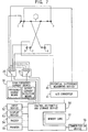
- FIG. 7 further embodiment of the present invention is shown in which two potential difference measurement electrodes are each attached to the right hand and the right foot, and four high frequency current application electrodes are each attached to both hands and both feet.
- each of the impedance "Z1+Z3", “Z5" and “Z6" can be determined in one measurement operation simply by changing the current application path.
- a pair of the high frequency current application electrode and the potential difference measurement electrode is attached to both hands and both feet, respectively.
- each of the impedance "Z1+Z3", “Z2+Z4", “Z5", “Z6” and”Z7" for all the parts of the body can be determined in one measurement operation by independently changing the current application path and the potential difference measurement path.
- the living impedance on each of the parts of a human body can easily be measured so that calculation and assessment of the body composition on each of the parts can be performed. Therefore, the whole body composition derived from such results is contributed by the living impedance information in whole body, thereby improving the accuracy in measurement for the whole body composition.
- the composition on only a part of the body is known, the measurement on only that part of the body can be done. It takes shorter time period and relieves the discomfort of a person to be tested.
- the information indicating the parts of the body to be measured and the changing sequence of the electrodes required for the measurement may be entered to the system in advance as the measurement parameters.
- any specified part of the body can be measured simply by selecting any one of the parameters without any complicated operation.
- Such measurement and operation can easily be done by everybody or unskilled person.
Abstract
High frequency current application electrodes are brought into contact
with both hands, both feet, etc., which are extreme parts of a body in order to
apply current to the parts of the body to be measured. Potential difference
measuring electrodes are brought into contact with the parts to be measured
along the path of the high frequency current. High frequency current
application electrodes and potential difference measuring electrodes are
selected to select the path of the high frequency current and the path of the
potential difference measurement in accordance with the purpose.
Impedance on each of the parts of the body is measured and body composition
is derived.
Description
- The present invention relates to a living body impedance measuring instrument, and a body composition measuring instrument for producing a body composition in a whole body or in a part of a body of a person to be tested, based upon the living body impedance measured.
- It is well known to predict a body composition using a living body impedance (see, for example, "Assessment of fat-free mass using bio-electrical impedance measurement of the human body", The American Journal of Clinical Nutrition, 41(4), 810-817, 1985). A number of body fat measuring instruments based on this principle have been proposed (see, for example, USP No. 4,008,721; Japanese Patent Publication No. 5-49050; and Japanese Utility Model Laid-Open No. 3-27050) and a number of "BIM" type body fat measuring instruments are now available in the market.
- Those prior art instruments include two high frequency current application electrodes and two potential difference measurement electrodes required for measuring the living body impedance. One high frequency current application electrode is paired with one potential difference measurement electrode, and a high frequency current application terminal and a potential difference measurement terminal are disposed at the same end. Then they are attached to hands or feet of a human body. In order to produce a body composition, impedance values measured between a hand and a foot, between both feet or between both hands are basically utilized to derive a whole body composition. Therefore, in the past, the body composition is not necessarily produced by taking into account of a living impedance data in a whole body.
- If it is necessary to change the parts to be measured for getting more precision in measurement, it is frequently difficult to remove and re-attach the electrodes because of paired connection of the high frequency current application electrodes and the potential difference measuring electrodes. Sometime, it is even necessary to take off one's clothes depending on the parts to be measured.
- The prior art four-electrode measuring process can only measure the living body impedance between both feet or between both hands. Accordingly, it is difficult to measure the living body impedance a part by a part of the body.
- Therefore, in case where the living body impedance should be measured a part by a part of the body, it is necessary for a skilled parson to attach four or more electrodes to the relevant parts of the body. In addition, the voltage value measured should be converted into the data such as the impedance on the parts or the body compositions by using highly complicated calculation process. This involves highly expert knowledge and complicated arithmetic operations.
- Another approach has been attempted using four pairs of electrodes each mounted for each of both hands and both feet. The electrodes are switched to perform measurement between different parts of the body. For example, the measurement may be performed between both hands, both feet, the right hand and the right foot, the right hand and the left foot the left hand and the left foot or the left hand and the right foot (see Japanese Patent Laid-Open No. 9-285455).
- However, such approach is defective in that the data required for calculating the values on the parts to be measured involves many unnecessary components so that the measuring process is highly complicated. In addition, even when it is desired to only measure the main body portion, it is very cumbersome to perform because of four different types of data and the different calculations based on such data required. Furthermore, because of possibility of relatively large error inherently generated in the measurement of living body impedance, an amount of error cumulatively increases in proportion to the number of different data types used. Therefore, such approach involves a higher risk especially when it is used to measure the lower impedance portions such as the main body portion.
- In view of the above, there is a need to mitigate or to eliminate the disadvantages of the prior art devices as above. Therefore, one object of the present invention is to provides an improved measuring system that requires no cumbersome repeated attaching and detaching operations for the electrodes, that permits easy measurement of the impedance on each of different parts of a body, and that can produce precise values of body compositions based on the impedance data measured.
- According to the present invention, high frequency current application electrodes are brought into contact with both hands, both feet, etc., which are extreme parts of a body in order to apply current to the parts of the body to be measured. Potential difference measurement electrodes are brought into contact with the parts to be measured along the path of the high frequency current. High frequency current application electrodes and potential difference measurement electrodes are selected to select the path of the high frequency current and the path of the potential difference measurement in accordance with the purpose.
- Potential difference is allowed to be appeared only on the parts of a body that are included in the path of high frequency current according to 4-terminal law, and therefore, potential difference in any of sections along the path of high frequency current can be measured. As the result, the path of high frequency current and the potential difference measuring sections along the path can be selected in any combination to measure the impedance on desired parts of the body.
-
- Fig. 1 is a block diagram of a system comprising a living body impedance measuring instrument and a body composition measuring instrument according to one embodiment of the present invention;
- Fig. 2 is an equivalent circuit diagram of the living body impedance measuring instrument and the body composition measuring instrument according to one embodiment of the present invention;
- Fig. 3 is an equivalent circuit diagram of the living body impedance measuring instrument and the body composition measuring instrument when they are arranged to measure the impedance on both legs of a person;
- Fig. 4 is an equivalent circuit diagram of the living body impedance measuring instrument and the body composition measuring instrument when they are arranged to measure the impedance on an abdominal region of a person;
- Fig. 5 is an equivalent circuit diagram of the living body impedance measuring instrument and the body composition measuring instrument when they are arranged to measure the impedance on both arms of a person;
- Fig. 6 is an equivalent circuit diagram of the living body impedance measuring instrument and the body composition measuring instrument when they are arranged to measure the impedance on a chest portion of a person;
- Fig. 7 is a block diagram of a system comprising a living body impedance measuring instrument and a body composition measuring instrument according to another embodiment of the present invention;
- Fig. 8 is a block diagram of a system comprising a living body impedance measuring instrument and a body composition measuring instrument according to further embodiment of the present invention;
- Fig. 9 is a block diagram of a system comprising a living body impedance measuring instrument and a body composition measuring instrument according to yet further embodiment of the present invention; and
- Fig. 10 is a flow chart showing the operations of the system according to the present invention.
-
- Referring now to Fig. 1, one embodiment of the present invention is shown in a block diagram. A body composition measuring instrument as shown in the figure comprises total ten electrodes. More particularly one high frequency current application electrode and one potential difference measurement electrode are mounted on each of both hands and both feet which are extreme parts of a body. In addition, one potential difference measurement electrode is mounted on each of the roots of both arms.
- In the figure,
reference numerals electrodes current source 30.Electrodes difference measuring device 40, and the switching means 21 is connected to output terminals of the high frequencycurrent source 30. Theelectrodes - The switching means 20, 21, 22 and 23 are connected to a control, arithmetic and
storage device 50 so that they can independently operate to switch the electrodes according to control signals from thedevice 50. - The high frequency
current source 30 connected to the switching means 20 and 21 comprises a current detection means for detecting its output current and a frequency change means for changing the frequency of high frequency current, both means are connected to the control, arithmetic andstorage device 50. The current detection means functions to inform the detection result to the arithmetic andstorage device 50, and the frequency change means functions to change the frequency of high frequency current according to the control signals from the control, arithmetic andstorage device 50. - The switching means 22 and 23 are connected to the potential
difference measuring device 40 whose output is connected to the control, arithmetic andstorage device 50 via an A/D converter 41. The A/D converter 41 functions to convert the output of the potentialdifference measuring device 40 into digital values which are then fed to the control, arithmetic andstorage device 50. - An
input device 52 is connected to the control, arithmetic andstorage device 50 for entering some instructions for operations of the system and parameters for a person to be tested such as height and weight of the person. - A
display device 53 connected to the control, arithmetic andstorage device 50 functions to display parameter settings for the person to be tested, measurement results, and some indications indicating when an error occurs. Abuzzer 54 is activated to generate a tone at the time when the measurement is started, the measurement is completed, and any error occurs. Aprinter 55 produces a hard copy of the measurement results. - A
communication device 56 is connected to the control, arithmetic andstorage device 50 in order to communicate between the system and the external devices. Thecommunication device 56 functions to transmit the measurement results to the external devices, while it receives the parameters for the person to be tested and the instructions for operation of the system from the external devices. - In the embodiment as shown, a memory card is used for the removable storage medium. The parameters used for the measurement and the data such as the measurement results are stored in the memory card through the control, arithmetic and
storage device 50. - The control, arithmetic and
storage device 50 functions to selectively activate the switching means 20, 21, 22 and 23 and to control changing of the frequency of the high frequency current. In addition, thedevice 50 functions to perform an arithmetic operation, based on the data or parameters for the person to be tested (which are entered from the input device, the communication device and the memory card), as well as on the data obtained by the measurement. As the result, thedevice 50 produces the values of impedance and the body composition, which are then fed to the output devices, the communication device and the memory card. - A sequence of measuring steps and details of measurement in this embodiment will be described below (with reference to Fig. 10 that shows the flow of the measurement steps). In this embodiment, in order to prevent excessive current from passing through the body due to any defect of the device, before attaching the electrodes to the body, the same electrode is selected by the switching means 20 and 21. This is for the purpose of self-diagnosis for finding out whether the output current is at normal level or at abnormal level. If it is found that the output current is at abnormal level, the measurement is stopped with an indication on the display device that indicates some abnormal condition prevailing in the system.
- If the self-diagnosis is successfully done, the parameters for the person to be tested and the instructions for operations of the system are entered by the
input device 52. Then, the electrodes are attached to both hands, both feet and the roots of both arms. - Before starting the measurement process, in order to examine the contact condition of each electrode, any two different electrodes are selected by the switching means 20 and 21, and the check is made to see if the current passing therebetween is at normal level or not. If an abnormal current passes, it means that any one of or both of the electrodes selected is in poor contact or no contact condition.
- More particularly, while the
electrode 1 is kept selected by the switching means 20, one of theelectrodes 2 to 10 is sequentially selected by the switching means 21 for examination. If it is found that an abnormal current passes when theelectrodes electrodes electrodes 2 to 10 are found abnormal after they are sequentially selected by the switching means 21. In such case, theelectrodes 2 is kept selected by the switching means 20 and any one of the electrodes 3 to 10 is sequentially selected by the switching means 21. In such manner, any poor contact or no contact condition of the electrodes can be detected. - Because of all the electrodes arranged to apply current to the body, the examination of the electrode contact condition can be performed depending on whether the current passing to the body from the high frequency current source is at normal level, or within the normal range, or at abnormal level. This greatly reduces the time period required for the examination. In view of such examination made before starting the measurement, it is unlikely that the measurement process would inevitably be interrupted in the course of measurement due to any defective contact of the electrodes.
- If any abnormal is found out in the examination of electrode contact condition, the buzzer device may sound and/or the display device may display which electrode (or electrodes) is in poor contact or no contact condition, or which electrode is becoming to such condition.
- If no abnormal is found in the examination of electrode contact condition, then the measurement is started.
- For the purpose of describing the present invention, some terms used herein are defined. Referring to Fig. 2 that is the equivalent circuit diagram of the human body, "Z1" and "Z2" mean the impedance of arms; "Z3" and "Z4" mean the impedance of the chest portion; "Z5" means the impedance of the abdominal region; and "Z6" and "Z7" mean the impedance of legs. The
electrodes electrodes electrodes 3 and 7 are attached to the right foot. Theelectrodes 4 and 8 are attached to the left foot. Finally, theelectrode 9 is attached to the root of the right arm, and theelectrode 10 is attached to the root of the left arm. Then, the impedance "Z1" is called a "right arm impedance"; "Z2" a "left arm impedance"; "Z3" a "right chest impedance"; "Z4" a "left chest impedance"; "Z5" a "abdominal impedance"; "Z6" a "right leg impedance"; and "Z7" a "left leg impedance". - The seven impedance "Z1" to "Z7" as indicated in the equivalent circuit of a human body are then measured according to the present invention, as described below.
- When measuring the right leg impedance Z6, the
electrode 1 is selected by the switching means 20, the electrode 3 is selected by the switching means 21, theelectrode 8 is selected by the switching means 22, and theelectrode 7 is selected by the switching means 23. Then, as shown in Fig. 3, the high frequency current I flows through the impedance Z1, Z3, Z5 and Z6 between theelectrodes 1 and 3, but it does not flow through the impedance Z7. Therefore, potential difference as measured between theelectrodes - Similarly, when measuring the left leg impedance Z7, the
electrode 2 is selected by the switching means 20, the electrode 4 is selected by the switching means 21, theelectrode 7 is selected by the switching means 22, and theelectrode 8 is selected by the switching means 23. Then, the high frequency current I flows through the impedance Z2, Z4, Z5 and Z7 between theelectrodes 2 and 4, but it does not flow through the impedance Z6. Therefore, potential difference as measured between theelectrodes - When measuring the abdominal impedance Z5, the
electrode 1 is selected by the switching means 20, the electrode 3 is selected by the switching means 21, theelectrode 6 is selected by the switching means 22, and theelectrode 8 is selected by the switching means 23. Then, as shown in Fig. 4, the high frequency current I flows through the impedance Z1, Z3, Z5 and Z6 between theelectrodes 1 and 3, but it does not flow through the impedance Z2, Z4 and Z7. Therefore, potential difference as measured between theelectrodes - When measuring the right arm impedance Z1, the
electrode 1 is selected by the switching means 20, the electrode 3 is selected by the switching means 21, theelectrode 5 is selected by the switching means 22, and theelectrode 9 is selected by the switching means 23. Then, as shown in Fig. 5, the high frequency current I flows through the impedance Z1, Z3, Z5 and Z6 between theelectrodes 1 and 3. Therefore, potential difference as measured between theelectrodes - Similarly, when measuring the left arm impedance Z2, the
electrode 2 is selected by the switching means 20, the electrode 4 is selected by the switching means 21, theelectrode 6 is selected by the switching means 22, and theelectrode 10 is selected by the switching means 23. Then, the high frequency current I flows through the impedance Z2, Z4, Z5 and Z7 between theelectrodes 2 and 4. Therefore, potential difference as measured between theelectrodes - When measuring the right chest impedance Z3, the
electrode 1 is selected by the switching means 20, the electrode 3 is selected by the switching means 21, theelectrode 9 is selected by the switching means 22, and theelectrode 10 is selected by the switching means 23. Then, as shown in Fig. 6, the high frequency current I flows though the impedance Z1, Z3, Z5 and Z6 between theelectrodes 1 and 3, but it does not flow through the impedance Z4. Therefore, potential difference as measured between theelectrodes - Similarly, when measuring the left chest impedance Z4, the
electrode 2 is selected by the switching means 20, the electrode 4 is selected by the switching means 21, theelectrode 10 is selected by the switching means 22, and theelectrode 9 is selected by the switching means 23. Then, the high frequency current I flows through the impedance Z2, Z4, Z5 and Z7 between theelectrodes 2 and 4, but it does not flow through the impedance Z3. Therefore, potential difference as measured between theelectrodes - As described above, the impedance on each of the parts of the body as shown in Fig. 2 are measured in accordance with 4-terminal law. The measurement results are transmitted to the control, arithmetic and
storage device 50. On the other hand, the data such as the parameters of the person to be tested are entered and stored in the control, arithmetic andstorage device 50 by using the input device in advance. The control, arithmetic andstorage device 50 performs the arithmetic operations based on the measurement results and the parameter data to produce the body composition in part of or in whole of the body as well as the distribution for each of the composition components. As the result, the difference in right-to-left of the arms, chest portions and legs can be derived and they are output to the display device for indication. - In addition, the impedance measurement is performed again, but with the change in frequency of the high frequency current, and "Cole-Cole plot law" is applied to the measurement results. Then, the amount of intracellular or extracellular fluid as well as the water content in each of the parts of the body can be derived. The measurement results and the parameters of a persons to be tested can partly or wholly be output to the printer device for printing, or transmitted to the external devices via the communication device, or stored in the memory card, depending on the applications, under the control of the control, arithmetic and
storage device 50. - One embodiment of the present invention has been described above. However, depending on the selection of the electrodes used for the measurement, the measurement of only living impedance between both hands, between both feet, or between a hand and a foot can, of course, be done, as in the case of the prior art.
- Apart from the embodiment as above wherein all the parts of the body are measured, only some of the parts, for example, the upper half of the body including both arms and chest portions, may be measured. In such case, the difference in composition for right and left arms and chest portions can be determined from the measurement results.
- Forgoing is the description of the embodiment wherein the impedance on all the parts of the body are measured. Referring to Fig. 8, another embodiment of the present invention is shown in which two high frequency current application electrodes are each attached to the right hand and the right foot, and four potential difference measurement electrodes are each attached to both hands and both foot. According to this embodiment, each of the impedance "Z1 + Z3", "Z5" and "Z6" can be determined in one measurement operation simply by changing the measurement path. Although not shown in the figure, another arrangement is possible wherein two high frequency current application electrodes are each attached to both hands, and four potential difference measurement electrodes are each attached to both hands and to the roots of both arms. In such case, the impedance "Z1" and "Z2" can be determined by changing the potential difference measurement path.
- Referring to Fig. 7, further embodiment of the present invention is shown in which two potential difference measurement electrodes are each attached to the right hand and the right foot, and four high frequency current application electrodes are each attached to both hands and both feet. According to such embodiment, each of the impedance "Z1+Z3", "Z5" and "Z6" can be determined in one measurement operation simply by changing the current application path. Referring to Fig. 9, yet further embodiment of the present invention is shown in which a pair of the high frequency current application electrode and the potential difference measurement electrode is attached to both hands and both feet, respectively. According to such embodiment, each of the impedance "Z1+Z3", "Z2+Z4", "Z5", "Z6" and"Z7" for all the parts of the body can be determined in one measurement operation by independently changing the current application path and the potential difference measurement path.
- It is apparent from the foregoing that the living impedance on each of the parts of a human body can easily be measured so that calculation and assessment of the body composition on each of the parts can be performed. Therefore, the whole body composition derived from such results is contributed by the living impedance information in whole body, thereby improving the accuracy in measurement for the whole body composition.
- If it is desired that the composition on only a part of the body is known, the measurement on only that part of the body can be done. It takes shorter time period and relieves the discomfort of a person to be tested.
- In case where a person was injured on one arm and was subjected to treatment for longer period of time, it is effective to use the composition on the normal arm as the criteria of decision for restoration. In such case, only the part of the body that the person wants to know can be measured within shorter period of time, which relieves the discomfort of the injured person.
- Furthermore, the information indicating the parts of the body to be measured and the changing sequence of the electrodes required for the measurement may be entered to the system in advance as the measurement parameters. In such case, any specified part of the body can be measured simply by selecting any one of the parameters without any complicated operation. Such measurement and operation can easily be done by everybody or unskilled person.
Claims (23)
- A living body impedance measuring instrument using 4-terminal law, characterized in that it comprises:a high frequency current generation source; three or more high frequency current application electrodes for applying the high frequency current to the living body;a switching means for enabling application of the current along the different current paths to said high frequency current application electrodes;a potential difference measuring device; two potential difference measurement electrodes for measuring the potential difference;a control and arithmetic device;a storage device; andan output means;
whereby said current path switching means is connected to such high frequency current application electrodes that allows measurement of an impedance on the target part of the body under the control of said control and arithmetic device;a voltage value obtained from said potential difference measuring device is converted into the impedance value of said target part in said arithmetic device;said impedance value is stored in said storage device; andsaid impedance value is output to said output means. - A living body impedance measuring instrument using 4-terminal law, characterized in that it comprises:a high frequency current generation source;two high frequency current application electrodes for applying the high frequency current to the living body;a potential difference measuring device;three or more potential difference measurement electrodes for measuring the potential difference;a switching means for enabling measurement of the potential difference on the different parts of the body by said potential difference measurement electrodes;a control and arithmetic device; andan output means;
whereby the high frequency current is applied to the living body via said two high frequency current application electrodes;said switching means is connected to such potential difference measurement electrodes that can measure potential difference on the target part of the body under the control of said control and arithmetic device;a voltage value obtained from said potential difference measuring device is converted into the impedance value of said target part in said arithmetic device;said impedance value is stored in a storage device; andsaid impedance value is output to said output means. - A living body impedance measuring instrument using 4-terminal law, characterized in that it comprises:a high frequency current generation source;three or more high frequency current application electrodes for applying the high frequency current to the living body;a first switching means for enabling application of the current along the different current paths to said high frequency current application electrodes;a potential difference measuring device;three or more potential difference measurement electrodes for measuring the potential difference;a second switching means for enabling measurement of the potential difference on the different parts of the body by said potential difference measurement electrodes;a control and arithmetic device; andan output means;
whereby the high frequency current application electrodes and the potential difference measurement electrodes are independently switched in such combination that the potential difference on the target part of the body can be measured under the control of said control device;a voltage value obtained from said potential difference measuring device is converted into the impedance value of said target part in said arithmetic device;said impedance value is stored in a storage device; andsaid impedance value is output to said output means. - A living body impedance measuring instrument using 4-terminal law, characterized in that it comprises:four or more electrodes;a high frequency current generation source;a potential difference measuring device;a switching means for selectively connecting said high frequency current generation source or the potential difference measuring device to each of said four or more electrodes;a control and arithmetic device; andan output means;
whereby the high frequency current application electrodes and the potential difference measurement electrodes are independently switched in such combination that the potential difference on the target part of the body can be measured under the control of said control device;a voltage value obtained from said potential difference measuring device is converted into the impedance value of said target part in said arithmetic device;said impedance value is stored in a storage device; andsaid impedance value is output to said output means. - A living body impedance measuring instrument according to any one of Claims 1 to 4 wherein it further comprises an input means; andsaid control device instructs to switch the high frequency application electrodes and the potential difference measurement electrodes depending on the input information for measuring only the required part of the body;said arithmetic device operates to convert a voltage value obtained into the impedance value of said required part of the body;said impedance value is stored in a storage device; andsaid impedance value is output to said output means.
- A living body impedance measuring instrument according to Claims 3 and 5 wherein it comprises:four high frequency current application electrodes each brought into contact with each of both hands and both feet which are extreme parts of the body; andfour potential difference measurement electrodes each brought into contact with each of both hands and both feet which are extreme parts of the body and each along the path of the high frequency current applied by said high frequency current application electrodes.
- A living body impedance measuring instrument according to Claims 3 and 5 wherein it comprises:four high frequency current application electrodes each brought into contact with each of both hands and both feet which are extreme parts of the body;four potential difference measurement electrodes each brought into contact with each of both hands and both feet which are extreme parts of the body and each along the path of the high frequency current applied by said high frequency current application electrodes; andtwo additional potential difference measurement electrodes each brought into contact with each of the roots of both arms.
- A living body impedance measuring instrument according to Claims 2 and 5 wherein it comprises:two high frequency current application electrodes each brought into contact with each of both hands which are extreme parts of the body;two potential difference measurement electrodes each brought into contact with each of both hands which are extreme parts of the body and each along the path of the high frequency current applied by said high frequency current application electrodes; andtwo additional potential difference measurement electrodes each brought into contact with each of the roots of both arms.
- A body composition measuring instrument in combination with a living body impedance measuring instrument according to Claims 1 to 8 wherein it produces a body composition in a whole body, a body composition in a part of the body, or both of them, based upon the living body impedance as derived from said living body impedance measuring instrument, and upon the physical characteristics of a person to be tested such as height, weight, etc. of the person.
- A body composition measuring instrument in combination with a living body impedance measuring instrument according to Claims 1 to 8 wherein it produces a body composition in a whole body, a body composition in a part of the body, or both of them, based upon the living body impedance as derived from said living body impedance measuring instrument, and upon the physical characteristics of a part to be measured such as length, diameter, etc.
- A living body impedance measuring instrument according to Claims 1 to 8 wherein the parts of the body to be measured and the voltage measurements are stored in the storage device with mutually corresponding relationship, and calculation of the impedance is performed with a formula corresponding to each of the parts to be measured.
- A body composition measuring instrument according to Claims 9 and 10 wherein the parts of the body to be measured and the voltage measurements are stored in the storage device with mutually corresponding relationship, and calculation of the impedance is performed with a formula corresponding to each of the parts to be measured.
- A living body impedance measuring instrument according to Claims 1 to 8 wherein it comprises a removable recording medium; and wherein said control device instructs to store the data derived by the measurement and arithmetic operation to said recording medium.
- A body composition measuring instrument according to Claims 9 and 10 wherein it comprises a removable recording medium; and wherein said control device instructs to store the data derived by the measurement and arithmetic operation to said recording medium.
- A living body impedance measuring instrument according to Claims 1 to 8 wherein it comprises a communication device for communication with the outside of the instrument; and wherein said control device instructs to output the data derived by the measurement and arithmetic operation via the communication device.
- A body composition measuring instrument according to Claims 9 and 10 wherein it comprises a communication device for communication with the outside of the instrument; and wherein said control device instructs to output the data derived by the measurement and arithmetic operation via the communication device.
- A living body impedance measuring instrument according to Claims 1 to 8 wherein it comprises a communication device for communication with the outside of the instrument; and wherein said control device instructs to input the data required for the arithmetic operation via the communication device.
- A body composition measuring instrument according to Claims 9 and 10 wherein it comprises a communication device for communication with the outside of the instrument; and wherein said control device instructs to input the data required for the arithmetic operation via the communication device.
- A living body impedance measuring instrument according to Claims 1 to 8 wherein it operates to change the frequency of the high frequency current according to a control signal from the control device and to apply it to the living body.
- A body composition measuring instrument according to Claims 9 and 10 wherein it operates to change the frequency of the high frequency current according to a control signal from the control device and to apply it to the living body.
- A living body impedance measuring instrument according to Claims 1 to 8 wherein the measurement is performed, based upon the information about the parts to be measured or measurement parameters that are already stored and upon the electrode switching information for selecting the electrodes; or alternatively the measurement is performed, based upon a measurement parameter which is selected among a plurality of the measurement parameters already stored.
- A body composition measuring instrument according to Claims 9 and 10 wherein the measurement is performed, based upon the information about the parts to be measured or measurement parameters that are already stored and upon the electrode switching information for selecting the electrodes; or alternatively the measurement is performed, based upon a measurement parameter which is selected among a plurality of the measurement parameters already stored.
- A combination of a living body impedance measuring instrument and a body composition measuring instrument, characterized in that it comprises:a detection means for detecting whether an electrode is in contact with the living body or not; anda control device for acting in such manner that when it is found that there is no contact present between the electrode and the living body it outputs no data produced by a measurement and arithmetic operation to an output device or it informs the output device that there is no contact present between the electrode and the living body.
Applications Claiming Priority (3)
| Application Number | Priority Date | Filing Date | Title |
|---|---|---|---|
| JP5424497 | 1997-02-24 | ||
| JP5424497 | 1997-02-24 | ||
| PCT/JP1998/000736 WO1998036686A1 (en) | 1997-02-24 | 1998-02-24 | Living body impedance measuring instrument and body composition measuring instrument |
Publications (2)
| Publication Number | Publication Date |
|---|---|
| EP1013221A1 true EP1013221A1 (en) | 2000-06-28 |
| EP1013221A4 EP1013221A4 (en) | 2001-05-02 |
Family
ID=12965138
Family Applications (1)
| Application Number | Title | Priority Date | Filing Date |
|---|---|---|---|
| EP98904425A Withdrawn EP1013221A4 (en) | 1997-02-24 | 1998-02-24 | Living body impedance measuring instrument and body composition measuring instrument |
Country Status (5)
| Country | Link |
|---|---|
| US (1) | US6393317B1 (en) |
| EP (1) | EP1013221A4 (en) |
| KR (1) | KR20000075585A (en) |
| AU (1) | AU6230298A (en) |
| WO (1) | WO1998036686A1 (en) |
Cited By (3)
| Publication number | Priority date | Publication date | Assignee | Title |
|---|---|---|---|---|
| WO2004048983A1 (en) * | 2002-11-27 | 2004-06-10 | Z-Tech (Canada) Inc. | Improved apparatus and method for performing impedance measurements |
| US6790178B1 (en) * | 1999-09-24 | 2004-09-14 | Healthetech, Inc. | Physiological monitor and associated computation, display and communication unit |
| EP1917907A1 (en) * | 2000-12-28 | 2008-05-07 | Z-Tech (Canada) Inc. | Electrical impedance method and apparatus for detecting and diagnosing diseases |
Families Citing this family (40)
| Publication number | Priority date | Publication date | Assignee | Title |
|---|---|---|---|---|
| US6141585A (en) * | 1998-05-08 | 2000-10-31 | Intermedics Inc. | Implantable cardiac stimulator with electrode-tissue interface characterization |
| JP4357049B2 (en) * | 1999-10-07 | 2009-11-04 | 大和製衡株式会社 | Body fat measuring device |
| JP4530232B2 (en) * | 1999-10-12 | 2010-08-25 | 株式会社タニタ | Biometric device |
| US6482158B2 (en) | 2000-05-19 | 2002-11-19 | Healthetech, Inc. | System and method of ultrasonic mammography |
| JP4671467B2 (en) * | 2000-05-31 | 2011-04-20 | 大和製衡株式会社 | Impedance measuring device |
| JP4632490B2 (en) * | 2000-07-18 | 2011-02-16 | 大和製衡株式会社 | Body fat mass measuring device |
| US6865410B2 (en) * | 2000-08-04 | 2005-03-08 | Electric Power Research Institute, Inc. | Apparatus and method for measuring current flow in an animal or human body |
| WO2002026112A2 (en) | 2000-09-29 | 2002-04-04 | Healthetech, Inc. | Indirect calorimetry system |
| JP3698633B2 (en) * | 2000-10-25 | 2005-09-21 | 株式会社タニタ | Body type identification device |
| US6607387B2 (en) | 2000-10-30 | 2003-08-19 | Healthetech, Inc. | Sensor system for diagnosing dental conditions |
| JP4671490B2 (en) * | 2000-11-17 | 2011-04-20 | 大和製衡株式会社 | Body impedance measuring device |
| GB0106250D0 (en) * | 2001-03-13 | 2001-05-02 | Hall Effect Technologies Ltd | Apparatus and method for analysing blood |
| US6625487B2 (en) * | 2001-07-17 | 2003-09-23 | Koninklijke Philips Electronics N.V. | Bioelectrical impedance ECG measurement and defibrillator implementing same |
| JP3653519B2 (en) * | 2002-06-12 | 2005-05-25 | ヤーマン株式会社 | Body composition measuring device |
| JP2004329412A (en) * | 2003-05-02 | 2004-11-25 | Tanita Corp | Body composition measuring instrument |
| JP4600914B2 (en) * | 2003-10-08 | 2010-12-22 | 株式会社タニタ | Body type identification device |
| JP2006198334A (en) * | 2005-01-24 | 2006-08-03 | Tanita Corp | Bioelectrical impedance measuring device and body composition measuring apparatus |
| JP4529884B2 (en) * | 2005-11-30 | 2010-08-25 | オムロンヘルスケア株式会社 | Body fat measuring device and upper limb unit |
| JP4762765B2 (en) * | 2006-03-17 | 2011-08-31 | 富士通株式会社 | Biometric detection device, fingerprint authentication device, and biometric detection method |
| US8109883B2 (en) | 2006-09-28 | 2012-02-07 | Tyco Healthcare Group Lp | Cable monitoring apparatus |
| US8668651B2 (en) | 2006-12-05 | 2014-03-11 | Covidien Lp | ECG lead set and ECG adapter system |
| JP4812735B2 (en) * | 2007-11-15 | 2011-11-09 | 大和製衡株式会社 | Body fat scale |
| US8038484B2 (en) | 2007-12-11 | 2011-10-18 | Tyco Healthcare Group Lp | ECG electrode connector |
| US8548558B2 (en) * | 2008-03-06 | 2013-10-01 | Covidien Lp | Electrode capable of attachment to a garment, system, and methods of manufacturing |
| US20090227857A1 (en) * | 2008-03-06 | 2009-09-10 | Chuck Rowe | Biomedical electrode |
| US8868216B2 (en) * | 2008-11-21 | 2014-10-21 | Covidien Lp | Electrode garment |
| USD737979S1 (en) | 2008-12-09 | 2015-09-01 | Covidien Lp | ECG electrode connector |
| EP2305111A1 (en) * | 2009-10-01 | 2011-04-06 | seca ag | Bioimpedance measuring device and method |
| US8694080B2 (en) | 2009-10-21 | 2014-04-08 | Covidien Lp | ECG lead system |
| CA2746944C (en) | 2010-07-29 | 2018-09-25 | Tyco Healthcare Group Lp | Ecg adapter system and method |
| CN103687537B (en) | 2011-07-22 | 2016-02-24 | 柯惠有限合伙公司 | Ecg electrode connector |
| US8634901B2 (en) | 2011-09-30 | 2014-01-21 | Covidien Lp | ECG leadwire system with noise suppression and related methods |
| WO2013075270A1 (en) * | 2011-11-25 | 2013-05-30 | Yang Chang-Ming | Object, method, and system for detecting heartbeat or whether or not electrodes are in proper contact |
| CN102920454B (en) * | 2012-06-26 | 2014-09-17 | 北京四海华辰科技有限公司 | Human impedance measuring method, device and equipment |
| CN103123669B (en) * | 2013-02-28 | 2016-03-30 | 大连大学 | A kind of body composition analysis's method based on genetic algorithm |
| US9408546B2 (en) | 2013-03-15 | 2016-08-09 | Covidien Lp | Radiolucent ECG electrode system |
| EP2967396B1 (en) | 2013-03-15 | 2019-02-13 | Kpr U.S., Llc | Electrode connector with a conductive member |
| USD771818S1 (en) | 2013-03-15 | 2016-11-15 | Covidien Lp | ECG electrode connector |
| WO2015169911A1 (en) * | 2014-05-07 | 2015-11-12 | Koninklijke Philips N.V. | Method and apparatus for estimating the fluid content of part of the body of a subject |
| KR102265066B1 (en) | 2014-07-17 | 2021-06-15 | 삼성전자주식회사 | Method and apparatus for measuring bio impedance |
Citations (1)
| Publication number | Priority date | Publication date | Assignee | Title |
|---|---|---|---|---|
| US5579782A (en) * | 1993-08-12 | 1996-12-03 | Omron Corporation | Device to provide data as a guide to health management |
Family Cites Families (16)
| Publication number | Priority date | Publication date | Assignee | Title |
|---|---|---|---|---|
| CH563619A5 (en) | 1973-04-09 | 1975-06-30 | Siemens Ag | |
| JPS5244420Y2 (en) * | 1973-05-29 | 1977-10-08 | ||
| US4008721A (en) | 1975-04-14 | 1977-02-22 | Medtronic, Inc. | Tape electrode for transmitting electrical signals through the skin |
| US4008712A (en) | 1975-11-14 | 1977-02-22 | J. M. Richards Laboratories | Method for monitoring body characteristics |
| JPH052164Y2 (en) * | 1987-05-27 | 1993-01-20 | ||
| JP2830082B2 (en) | 1989-06-23 | 1998-12-02 | 三菱化学株式会社 | Developer for developing electrostatic images |
| JPH0549050A (en) | 1991-08-09 | 1993-02-26 | Sony Corp | Crt adjustment device |
| GB9222888D0 (en) * | 1992-10-30 | 1992-12-16 | British Tech Group | Tomography |
| JPH0712635A (en) | 1993-06-25 | 1995-01-17 | Ya Man Ltd | Body-fat measuring apparatus |
| JP3211118B2 (en) | 1993-09-14 | 2001-09-25 | オムロン株式会社 | Health management guideline advice device |
| US5824029A (en) * | 1994-04-28 | 1998-10-20 | Medtronic, Inc. | Implantable medical system for performing transthoracic impedance measurements associated with cardiac function |
| JP3240401B2 (en) * | 1994-12-07 | 2001-12-17 | オムロン株式会社 | Impedance measurement device and health management guideline advice device |
| JP3409095B2 (en) * | 1994-12-07 | 2003-05-19 | オムロン株式会社 | Impedance measurement device and health management guideline advice device |
| US6044294A (en) * | 1995-12-15 | 2000-03-28 | Pacesetter, Inc. | Methods and apparatus for measuring impedance in the body |
| JPH09285455A (en) | 1996-02-23 | 1997-11-04 | Omron Corp | Health management guide advising device |
| US6058325A (en) * | 1996-04-16 | 2000-05-02 | Cardiotronics | Method and apparatus for high current electrode, transthoracic and transmyocardial impedance estimation |
-
1998
- 1998-02-24 EP EP98904425A patent/EP1013221A4/en not_active Withdrawn
- 1998-02-24 US US09/367,349 patent/US6393317B1/en not_active Expired - Lifetime
- 1998-02-24 WO PCT/JP1998/000736 patent/WO1998036686A1/en not_active Application Discontinuation
- 1998-02-24 AU AU62302/98A patent/AU6230298A/en not_active Abandoned
- 1998-02-24 KR KR1019997007645A patent/KR20000075585A/en not_active Application Discontinuation
Patent Citations (1)
| Publication number | Priority date | Publication date | Assignee | Title |
|---|---|---|---|---|
| US5579782A (en) * | 1993-08-12 | 1996-12-03 | Omron Corporation | Device to provide data as a guide to health management |
Non-Patent Citations (2)
| Title |
|---|
| No further relevant documents disclosed * |
| See also references of WO9836686A1 * |
Cited By (3)
| Publication number | Priority date | Publication date | Assignee | Title |
|---|---|---|---|---|
| US6790178B1 (en) * | 1999-09-24 | 2004-09-14 | Healthetech, Inc. | Physiological monitor and associated computation, display and communication unit |
| EP1917907A1 (en) * | 2000-12-28 | 2008-05-07 | Z-Tech (Canada) Inc. | Electrical impedance method and apparatus for detecting and diagnosing diseases |
| WO2004048983A1 (en) * | 2002-11-27 | 2004-06-10 | Z-Tech (Canada) Inc. | Improved apparatus and method for performing impedance measurements |
Also Published As
| Publication number | Publication date |
|---|---|
| AU6230298A (en) | 1998-09-09 |
| US6393317B1 (en) | 2002-05-21 |
| EP1013221A4 (en) | 2001-05-02 |
| KR20000075585A (en) | 2000-12-15 |
| WO1998036686A1 (en) | 1998-08-27 |
Similar Documents
| Publication | Publication Date | Title |
|---|---|---|
| EP1013221A1 (en) | Living body impedance measuring instrument and body composition measuring instrument | |
| KR100372370B1 (en) | Body fat meter and body weight scales equipped with body fat meter | |
| EP1063500B9 (en) | Method and apparatus for measuring distribution of body fat | |
| JPH10510455A (en) | Human body component analyzer and analysis method using new electrode system based on bioelectric impedance analysis | |
| GB2304414A (en) | System for body impedance data acquisition utilizing segmental impedance and multiple frequency impedance measurement | |
| O'Brien et al. | A comparison of the British Hypertension Society and Association for the Advancement of Medical Instrumentation protocols for validating blood pressure measuring devices: can the two be reconciled? | |
| JP2008229364A (en) | Health management system | |
| EP1384435B1 (en) | Muscle fatigue measuring equipment | |
| JPH0549050B2 (en) | ||
| JP5110277B2 (en) | Body composition estimation device and body composition estimation method | |
| JPH10185A (en) | Diagnosing device for failure in body fluid | |
| JPH1170090A (en) | Bioelectricity impedance measuring device | |
| JP3492038B2 (en) | Body fat measurement device | |
| JP3636825B2 (en) | Body fat measuring device | |
| Burke et al. | Middle ear impedance measurements | |
| Popelka | Acoustic immittance measures: terminology and instrumentation | |
| Siervogel et al. | Bioelectric impedance measures of body composition: their relationship with level of blood pressure in young adults | |
| JP3636824B2 (en) | Body fat measuring device | |
| JP2005131434A (en) | Body condition estimating device | |
| JP3461646B2 (en) | Body fat measurement device | |
| JP3819611B2 (en) | Body composition estimation device | |
| US20220400973A1 (en) | Method, a device, and a system for estimating total body water content | |
| US20230233146A1 (en) | Edema detection | |
| RU2018297C1 (en) | Method and device for diagnosis of otoneurologic syndromes | |
| KR20020091488A (en) | Bioelectrical impedance analyzer |
Legal Events
| Date | Code | Title | Description |
|---|---|---|---|
| PUAI | Public reference made under article 153(3) epc to a published international application that has entered the european phase |
Free format text: ORIGINAL CODE: 0009012 |
|
| 17P | Request for examination filed |
Effective date: 19990916 |
|
| AK | Designated contracting states |
Kind code of ref document: A1 Designated state(s): DE FR GB |
|
| A4 | Supplementary search report drawn up and despatched |
Effective date: 20010322 |
|
| AK | Designated contracting states |
Kind code of ref document: A4 Designated state(s): DE FR GB |
|
| 17Q | First examination report despatched |
Effective date: 20030929 |
|
| STAA | Information on the status of an ep patent application or granted ep patent |
Free format text: STATUS: THE APPLICATION IS DEEMED TO BE WITHDRAWN |
|
| 18D | Application deemed to be withdrawn |
Effective date: 20041216 |