Technical Field
-
The present invention relates to a transmitting
apparatus and a receiving apparatus, which are mounted
on a radio communication apparatus, for changing a data
transmission rate in accordance with a network state,
and relates to a data transmitting method.
Background Art
-
In a radio communication system, there is a case
in which a data transmission method for adaptively
controlling a data transmission rate in accordance with
a network state so as to increase an average transmission
efficiency of data is used.
-
The following will explain a conventional radio
communication apparatus, which adaptively controls the
data transmission rate, with reference to the drawings.
-
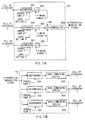
FIGS. 1A and 1B are block diagrams each showing the
configuration of the conventional radio communication
apparatus of a TDD transmission system. FIG. 1A is a
block diagram showing the configuration of a side that
adaptively controls the data transmission rate and
transmits data (hereinafter referred to as "transmitting
side"), and FIG. 1B is a block diagram showing the
configuration of a side that receives data whose
transmission rate adaptively controlled (hereinafter
referred to as "receiving side").
-
The transmitting side of the radio communication
apparatus shown in FIG. 1A comprises a data buffer 1 for
temporarily storing transmitting signals, a modulator
2 for providing BPSK modulation to the transmitting
signals, a modulator 3 for providing QPSK modulation to
the transmitting signals, a modulator 4 for providing
16QAM modulation to the transmitting signals, an
amplifier 5 for amplifying modulated signals, an antenna
6 for radio receiving and transmitting signals, a level
detector 7 for detecting the levels of the signals
received from the antenna 6, a rate selector 8 for
selecting a data transmission rate from the level of each
received signal so as to generate rate selective
information, which shows a data transmission rate, and
switches 9 and 10, which are switch-controlled by the
rate selector 8.
-
The receiving side of the radio communication
apparatus shown in FIG. 1B comprises an antenna 21 for
radio receiving and transmitting signals, an amplifier
22 for amplifying the received signals, a demodulator
23 for providing BPSK demodulation to the received
signals, a demodulator 24 for providing QPSK
demodulation to the received signals, a demodulator 25
for providing 16QAM demodulation to the received signals,
a data buffer 26 for storing demodulated signals, a BPSK
demodulator 27 for BPSK demodulating the received
signals so as to extract rate selective information, a
rate detector 28 for detecting a data transmission rate
from the output of the BPSK demodulator 27, and switches
29 and 30, which are switch-controlled by the rate
detector 28.
-
In the case of TDD transmission system, since the
propagation path for a reverse link is the same as for
a forward link, it is possible for the transmitting side
to measure the level of the received signal and to select
a modulation system of the transmitting signal based on
the level of the received signal.
-
The rate selector 8 of the transmitting side
determines that the network state is good when the level
of the received signal is high, and selects the
modulation system of such as 16QAM, etc., in which an
error occurs easily but a transmission rate is high, so
as to control switches 8 and 10. Also, the rate selector
8 determines that the network state is poor when the level
of the received signal is low, and selects the modulation
system of such as BPSK, etc., in which a transmission
rate is low but an error does not easily occurs, so as
to control switches 8 and 10. Furthermore, the rate
selector 8 stores rate selective information to the data
buffer 1.
-
The transmitting signal stored in the data buffer
1 is modulated by the modulation system selected by the
rate selector 8. However, the transmitting signal is
always modulated by BPSK system in order that errors are
not easily generated. The modulated signal is amplified
by the amplifier 5, thereafter the amplified signal is
radio transmitted from the antenna 6.
-
The signal received by the antenna 21 of the
receiving side is amplified by the amplifier 22,
thereafter rate selective information is extracted by
BPSK( demodulator 27, and a data transmission rate is
detected by the rate detector 28. Then, the switches 29
and 30 are switch-controlled based on the detected data
transmission rate, and the received signal is
demodulated by the demodulation system having the same
data transmission rate as that of the modulation system.
A demodulation result is stored in the data buffer 26
and then fetched as a received signal.
-
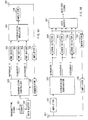
FIG. 2 is a block diagram showing the configuration
of the conventional radio communication apparatus of FDD
transmission system. FIG. 2A shows the configuration of
the transmitting side, and FIG. 2B shows the
configuration of the receiving side. In FIG. 2, the same
reference numerals as those of FIG. 1 are added to the
portions common to FIG. 1, and the explanation is
omitted.
-
In the case of FDD transmission system, since the
propagation path for the reverse line is different from
the propagation path for the forward line, the receiving
side measures the level of the received signal, and
selects a modulation system of the transmitting signal
based on the level of the received signal.
-
As compared with FIG. 1, the transmitting side of
the radio communication apparatus shown in FIG.2
comprises an amplifier 11 for amplifying received
signals, a demodulator 12 for extracting rate selective
information from the received signals and a rate detector
13 for detecting a data transmission rate from rate
selective information, in place of the level detector
7 and the rate selector 8.
-
Also, the receiving side comprises the level
detector 31 for detecting for detecting the level of each
received signal, a rate selector 32 for selecting a data
transmission rate from the level of the received signal
so as to generate rate selective information, which shows
a data transmission rate, a modulator 33 for modulating
rate selective information and an amplifier 34 for
amplifying modulated rate selective information, in
place of BPSK demodulator 27 and rate selector 28.
-
The rate selector 32 of the receiving side
determines that the network state is good when the level
of the received signal is high, and selects the
modulation system such as 16 QAM, etc., in which an error
is easily generated but a transmission rate is high, and
outputs rate selective information to the modulator 33.
Also, the rate selector 32 of the receiving side
determines that the network state is poor when the level
of the received signal is low, and selects the modulation
system such as BPSK, etc., in which a transmission rate
is low but an error is not easily generated, and outputs
rate selective information to the modulator 33. The
modulator 33 modulates the rate selective information
using the BPSK system in which the error is not easily
generated, and a modulated result is amplified by the
amplifier 34, and then transmitted to the transmitting
side from the antenna 21.
-
Also, the rate selector 32 outputs rate selective
information, and controls the switches 29 and 30 to make
preparations for performing demodulation corresponding
to a specified data transmission rate at the same time.
A demodulation result is stored in the data buffer 26,
and then fetched as a received signal.
-
The signal received by the antenna 6 of the
transmitting side is amplified by the amplifier 11, and
then demodulated by the demodulator 12, so that rate
selective information is extracted. Then, the rate
detector 13 detects a data transmission rate from rate
selective information and the switches 9 and 10 are
controlled, so that the data transmission rate of the
transmitting signal is determined.
-
The transmitting signal is temporarily stored in
the data buffer 1, and the stored signal is modulated
by any one of BPSK modulator 2, QPSK modulator 3, 16QAM
modulator 4 in accordance with the control of the rate
detector 13, and the modulated signal is amplified by
the amplifier 5, and transmitted from the antenna 6 of
the transmitting side.
-
Thus, the conventional radio communication
apparatus, which adaptively controls the rata
transmission rate, improves transmission efficiency
using the modulation system with a high transmission rate
when the network state is good, and transmits data
without fail using the modulation system, in which a data
transmission rate is low but an error is not easily
generated, when the network state is poor, and this
increases an average transmission efficiency of data.
-
However, the above conventional radio communication
apparatus must pass rate selective information between
the transmitting side and the receiving side, and has a
problem in which transmission efficiency drops when rate
selective information is in error. Also, there is a
problem in which only the reception level is not adequate
for determining the network state and accuracy in
estimation of receiving quality worsens when multipath
fading occurs. Moreover, there is a problem in which the
network state at a rate selecting time and the network
state at a signal transmitting time change when fading
speed is high, and this prevents transmission efficiency
from being sufficiently improved.
Disclosure of Invention
-
An object of the present invention is to provide a
transmitting apparatus and a receiving apparatus in which
a data transmission rate is automatically changed in
accordance with a network state without passing rate
selective information, and to provide a data transmitting
method.
-
The above object can be attached by the
configuration in which a transmitting side distributes
transmitting signals to a plurality of hierarchies in unit
of cell and provides coding processing such that an error
detection can be performed for each hierarchy and carries
out hierarchical modulation so as to transmit the signals,
and a receiving side demodulates received signals for each
hierarchy and performs an error detection, and provides
a re-transmission request to each hierarchy.
Brief Description of Drawings
-
- FIGS. 1A and 1B are block diagrams each showing a
configuration of a conventional radio communication
apparatus, which performs an adaptive modulation in TDD
transmission;
- FIGS. 2A and 2B are block diagrams each showing a
configuration of a conventional radio communication
apparatus, which performs an adaptive modulation in FDD
transmission;
- FIGS. 3A and 3B are block diagrams each showing a
configuration of a radio communication apparatus
according to Embodiment 1 of the present invention;
- FIGS. 4A and 4B are schematic views each showing
arrangement of signal points of hierarchical modulation
in QPSK modulation;
- FIGS. 5A and 5B are block diagrams each showing a
configuration of a radio communication apparatus
according to Embodiment 2 of the present invention;
- FIGS. 6 and 7 are flowcharts showing processing
actions of a transmission controller of the radio
communication apparatus of Embodiment 2 of the present
invention;
- FIG. 8 is a schematic view showing cells to be
written to TMP buffer of each hierarchy of the radio
communication apparatus of Embodiment 2 of the present
invention;
- FIGS. 9A and 9B are block diagrams each showing a
partial configuration of the radio communication
apparatus of Embodiment 3 of the present invention;
- FIGS. 10A and 10B are block diagrams each showing
a partial configuration of the radio communication
apparatus of Embodiment 4 of the present invention;
- FIGS. 11A and 11B are block diagrams each showing
a partial configuration of the radio communication
apparatus of Embodiment 5 of the present invention; and
- FIGS. 12A and 12B are block diagrams each showing
a partial configuration of the radio communication
apparatus of Embodiment 6 of the present invention.
-
Best Mode for Carrying Out the Invention
-
Embodiments of the present invention will be
specifically explained with reference to drawing
attached therewith.
(Embodiment 1)
-
FIG. 3 is a block diagram showing the configuration
of the radio communication apparatus according to
Embodiment 1 of the present invention. FIG. 3A shows a
side that hierarchically modulates data and transmits it
(hereinafter referred to as "transmitting side"), and FIG.
3B shows a side that receives hierarchically modulated
data (hereinafter referred to as "receiving side").
-
The transmitting side of the radio communication
apparatus shown in FIG. 3A comprises a coder 101 for
providing coding for an error detection to transmitting
signals, a data buffer 102 for temporarily storing the
coded transmitting signals, a hierarchical modulator 103
for hierarchically modulating the coded signals, an
amplifier 104 for amplifying the hierarchically
modulated signals, an antenna 105 for receiving and
transmitting signals, an amplifier 106 for amplifying a
re-transmission request signal from the receiving side,
and a demodulator 107 for demodulating the re-transmission
request signal.
-
The receiving side shown in FIG. 3B comprises an
antenna 151 for receiving and transmitting signals, an
amplifier 152 for amplifying received signals, a
hierarchical demodulator 153 for hierarchically
demodulating the received signals amplified, error
detectors 154, 155 for detecting errors of the received
signals, a data buffer 157 for temporarily storing the
received signals, a modulator 158 for modulating a
re-transmission request signal, and an amplifier 159 for
amplifying the re-transmission request signal.
-
The coder 101 of the transmitting side distributes
the transmitting signals to a plurality of hierarchies
in unit of cell and performs coding such that an error
detection can be carried out for each hierarchy, and
stores the result to the data buffer 102. The cell
distributed to each hierarchy is hierarchically
modulated by the hierarchical modulator 103, and the
modulation result is amplified by the amplifier 104, and
the amplified result is transmitted from the antenna 105.
-
Here, the hierarchical modulation is a system that
makes a difference in the quality between a plurality of
signals transmitted on the same network by putting some
contrivance of the arrangement of signal points thereby
performing modulation.
-
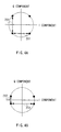
The following will explain the hierarchical
modulation by use of the view showing the arrangement of
signal points of QPSK modulation shown in FIG. 4. FIG.
4A shows the arrangement of signal points of general QPSK
modulation. In the general QPSK modulation, since a
distance 201 between signal points of I component and a
distance 202 between signal points of Q component are
equal to each other, the quality of I component is the
same as that of Q component. FIG. 4B shows the
arrangement of signal points of QPSK modulation to which
hierarchical modulation is provided. In QPSK modulation
to which hierarchical modulation is provided, since a
distance 251 between signal points of I component is
longer than a distance 252 between signal points of Q
component, the quality of I component is better than that
of Q component. Also, as compared with FIG. 4A, FIG. 4B
shows that the quality of Q component is bad but that of
I component is good.
-
The signal received by the antenna 151 is amplified
by the amplifier 152, and the amplified signal is
hierarchically demodulated by the hierarchical
demodulator 153 so as to pick up the cells of the
respective hierarchies. The hierarchically modulated
cells are subjected to error detection processing for each
hierarchy by the error detectors 154 and 155, and a
re-transmission request signal relating to the cell in
which an error has been detected is output. The re-transmission
request signal is modulated by the modulator
158 and the modulated signal is amplified by the amplifier
159, and the amplified signal is transmitted from the
antenna 151.
-
The re-transmission request signal transmitted from
the receiving side is detected by the demodulator 107 via
the antenna 105 and amplifier 106, and the detection
result is output to the data buffer 102. Then, the cell,
which has been requested to be re-transmitted, is
automatically read from the data buffer 102 again and
re-transmitted.
-
For example, assuming that hierarchies 1 and 2 of
FIG. 3 are I component and Q component of FIG. 4B,
respectively. Even in a case where the network state is
bad, hierarchy 1 with high quality can succeed in data
transmission, so that transmission efficiency, which
corresponds to BPSK data transmission rate with one bit
per one symbol, can be ensured. The cell transmitted from
hierarchy 2 is re-transmitted repeatedly until hierarchy
2 succeeds in data transmission. In this case, however,
if the number of re-transmissions exceeds the buffer size,
the corresponding cell is discarded.
-
While, in a case where the network state is good,
hierarchy 2 with low quality can also succeed in data
transmission in addition to hierarchy 1, so that
transmission efficiency, which corresponds to QPSK data
transmission rate with two bits per one symbol, can be
obtained.
-
Thus, the transmitting side distributes the
transmitting signals to the plurality of hierarchies in
unit of cell and provides coding processing such that
error detection can be performed for each hierarchy so
as to carry out hierarchical modulation, and the receiving
side performs error detection for each hierarchy, and this
makes it possible to adaptively control the data
transmission rate automatically in accordance with the
network state without passing rate selective information
there between.
-
Though Embodiment 1 explains the case in which the
number of hierarchies is two, there is no limitation in
the number of hierarchies, and any number of hierarchies
can be used in the present invention.
(Embodiment 2)
-
FIG. 5 is a block diagram showing the configuration
of the radio communication apparatus according to
Embodiment 2. FIG. 5A shows the transmitting side, and
FIG. 5B shows the receiving side. In FIG. 5, the same
reference numerals as those of FIG. 3 are added to the
same configuration elements as those of FIG. 3, and the
explanation is omitted.
-
As compared with FIG. 3, a transmission controller
301 for controlling the hierarchies of transmitting
signals, and TMP buffers 302, 303, 304 for temporarily
storing cells are added to the transmitting side of the
radio communication apparatus shown in FIG. 5. Also,
though FIG. 3 shows the case in which the number of
hierarchies is 2 and FIG. 5 shows a case in which the number
of hierarchies is 3 just for explanation, this makes no
fundamental difference there between.
-
The transmission controller 301 controls the
hierarchies of the respective cells stored in the data
buffer 102, and stores them to the TMP buffers 302, 303,
304. Also, delete processing of cells, which have been
written into the data buffer 102 and TMP buffers 302, 303,
304, is performed. Moreover, in a case where the re-transmission
request signal is input from the demodulator
107, the corresponding cell is written into the TMP buffer,
which is different from the previous one, thereby
controlling the re-transmitting cell to be transmitted
at the hierarchy, which is different from the previous
one.
-
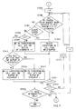
Next, an explanation is given of controlling actions
of transmission controller 301 by use of flowcharts of
FIGS. 6 and 7 and the schematic view of FIG. 8. In FIGS.
6 and 7, i denotes the number of hierarchies. Also, the
smaller the value of i is, the better the quality of
hierarchy becomes, and hierarchy 1 has the highest quality
and hierarchy I has the lowest quality.
-
First of all, at a transmission start time, all cells
written to TMP buffers 302, 303, 304, are deleted (ST401).
Next, transmission cells input from the data buffer 102
are written into vacant TMP buffers 302, 303, 304 (ST402).
The cells written into the respective TMP buffers are
hierarchically modulated by the hierarchical modulator
103, and the amplitude thereof is amplified by the
amplifier 104, and the result is radio transmitted from
the antenna 105.
-
If the transmission of transmission cells is
completed (ST403), all cells written into TMP buffers 302,
303, 304 are deleted (ST404).
-
Next, it is determined whether or not a re-transmission
request has been provided to the cell
transmitted at the hierarchy 2 from the receiving side
(ST405, ST406). Then, if the re-transmission request has
been provided to the corresponding cell in ST406, it is
determined whether or not the number of re-transmissions
of the corresponding cell exceeds the buffer size (ST407).
-
Then, if the number of re-transmissions of the
corresponding cell does not exceed the buffer size in
ST407, one rank of the hierarchy of re-transmitting cell
is moved up as compared with one previously transmitted,
and the corresponding cell is written to the TMP buffer
(ST408, and ST409). The transmission after moving up one
rank of the hierarchy of re-transmitting cell makes it
possible to transmit the cell automatically during the
repetition of re-transmission request at the hierarchy
where errors occur least. This makes it possible to
reduce the probability of the repetition of re-transmission
and a cell discard rate and to increase
reliability of transmission.
-
If the re-transmission request has not been provided
to the corresponding cell in ST406 or the number of
re-transmissions of the corresponding cell exceeds the
buffer size in ST407, the corresponding cell is deleted
from the data buffer 102 (ST410).
-
Then, the actions of ST406 to ST410 are repeatedly
provided to the transmitted cells of the hierarchy 3 to
hierarchy I (ST411, ST412, ST413).
-
Next, it is determined whether or not a re-transmission
request has been provided to the cell
transmitted at the hierarchy 1 from the receiving side
(ST414, ST406). Then, if the re-transmission request has
been provided thereto in ST406, it is determined whether
or not the number of re-transmissions of the corresponding
cell exceeds the buffer size (ST407).
-
Then, if the number of re-transmissions of the
corresponding cell does not exceed the buffer size in
ST407, it is determined whether or not the cell has been
already written to the TMP buffer of hierarchy 1 (ST408,
ST415).
-
If the cell has been already written to the TMP
buffer of hierarchy 1 in ST415, the corresponding cell
is written into the TMP buffer of hierarchy I (ST416).
-
Also, if the TMP buffer of hierarchy 1 is vacant in
ST415, the corresponding cell is written into the TMP
buffer of hierarchy 1 (ST417).
-
If no re-transmission request has been provided in
ST406 or the number of re-transmissions of the
corresponding cell exceeds the buffer size in ST407, the
corresponding cell is deleted from the data buffer 102
(ST410).
-
Then, it is determined whether or not non-transmitted
cell is left in the data buffer 102. Then,
if non-transmitted cell is left therein, the actions from
ST402 to ST417 are repeated. Moreover, if the
transmission of all cells is completed, the data
transmission is ended (ST418).
-
FIG. 8 is a schematic view showing the cells, which
are written into the TMP buffers of the respective
hierarchies of the radio communication apparatus
according to Embodiment 2.
-
First of all, in F501, cells P1, P2, and P3 are
written to hierarchies 1, 2, and 3, respectively.
-
As a result of the transmission in F501, if an error
occurs in only hierarchy 3, the receiving side provides
the re-transmission request of hierarchy 3 to the
transmitting side. In F502, cell P3 is written into
hierarchy 2 in accordance with the re-transmission
request. Also, new cells P4 and P5 are written into the
vacant hierarchies 1 and 3.
-
As a result of the transmission in F502, if all cells
are received with no error by the receiving side, no
re-transmission request is provided to the transmitting
side. Therefore, in F503, new cells P6, P7 and P8 are
written into all hierarchies.
-
As a result of the transmission in F503, if errors
occur in both hierarchies 2 and 3, the receiving side
provides the re-transmission requests of hierarchies 2
and 3 to the transmitting side. In F504, cell P7 is
written into hierarchy 1 in accordance with the re-transmission
request, and cell P8 is written into the
hierarchy. Also, a cell P9 is written into the vacant
hierarchy 3.
-
Here, there is a possibility that an error will occur
in not the hierarchy 3 but the hierarchy 2 with good
quality.
-
As a result of the transmission in F504, if an error
occurs in only hierarchy 2, the receiving side provides
the re-transmission request of hierarchy 2 to the
transmitting side. In F505, cell P8 is written into
hierarchy 1 in accordance with the re-transmission
request. Also, new cells P10 and P11 are written into
the vacant hierarchies 2 and 3.
-
As a result of the transmission in F505, if errors
occur in all hierarchies 2, the receiving side provides
the re-transmission requests of all hierarchies to the
transmitting side. In F506, cell P10 is written into
hierarchy 1, cell P11 is written into hierarchy 2, and
cell P8 is written into hierarchy 3 in accordance with
the re-transmission request.
-
As a result of the transmission in F506, if an error
occurs in only hierarchy 3, the receiving side provides
the re-transmission request of hierarchy 3 to the
transmitting side. In F507, cell P8 is written into
hierarchy 2 in accordance with the re-transmission
request. Also, new cells P12 and P13 are written into
the vacant hierarchies 1 and 3.
-
As a result of the transmission in F507, if errors
occur in hierarchies 2 and 3, the receiving side provides
the re-transmission requests of hierarchies 2 and 3 to
the transmitting side. Here, cell P8 is discarded since
it is delayed beyond the buffer size. Therefore, in F508,
cell P13 is written into hierarchy 2 in accordance with
the re-transmission request. Also, new cells P14 and P15
are written into the vacant hierarchies 1 and 3.
-
As a result of the transmission in F508, if an error
occurs in only hierarchy 1, the receiving side provides
the re-transmission request, of hierarchy 1 to the
transmitting side. Here, since no error occurs in
hierarchy 2, cell P14 is written into hierarchy 1 again,
and new cells P16 and P17 are written into the vacant
hierarchies 2 and 3 in F509.
-
As a result of the transmission in F509, if errors
occur in hierarchies 1 and 2, the receiving side provides
the re-transmission requests of hierarchies 1 and 2 to
the transmitting side. Here, since the error occurs in
hierarchy 2 in addition to hierarchy 1, in F510, cell P16
previously transmitted at hierarchy 2 is written into
hierarchy 1, and cell P14 previously transmitted at
hierarchy 1 is written into hierarchy 3. Also, new cell
P18 is written into the vacant hierarchy 2.
-
Thus, the hierarchies are used in rotation, and the
transmission is performed at the hierarchy different from
the previous one at the re-transmission time. This makes
it possible to automatically transmit the cell at the
hierarchy with the highest quality by repeating the
re-transmission even if the bad network state is continued
for a long period of time, and this allows the probability
of re-transmission and the cell discard rate to be
reduced.
-
In Embodiment 2, there is no limitation in the number
of hierarchies and a control algorithm. Moreover, in
Embodiment 2, though the hierarchy where the cell is
written is moved up one by one every re-transmission, it
is possible to perform the other control such as the
hierarchy where the re-transmitting cell is written is
unconditionally moved up to hierarchy 1.
(Embodiment 3)
-
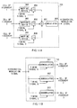
FIG. 9 is a block diagram showing the partial
configuration of the radio communication apparatus
according to Embodiment 3 of the present invention. FIG.
9A shows the configuration of the hierarchical modulator
of the radio communication apparatus, and FIG. 9B shows
the configuration of the hierarchical demodulator of the
radio communication apparatus.
-
The hierarchical modulator 103 shown in FIG. 9A
comprises a plurality of spreaders 601, 602, 603 for
performing spread processing, an adder 604 for adding
spread signals output from the respective spreaders, and
a modulator 605 for modulating the added spread signal.
-
The hierarchical demodulator 123 shown in FIG. 9B
comprises a plurality of despreaders 651, 652, 653 for
performing despread processing, and RAKE combining
devices 654, 655, 656 for RAKE combining outputs of the
respective despreaders.
-
The spreader 601 provides spread processing to the
cell distributed to hierarchy 1 using a spread code A,
and amplifies a spread signal based on a level setting
signal A. Similarly, the spreader 602 provides spread
processing to the cell distributed to hierarchy 2 using
a spread code B, and amplifies a spread signal based on
a level setting signal B. Also, the spreader 603 provides
spread processing to the cell distributed to hierarchy
3 using a spread code C, and amplifies a spread signal
based on a level setting signal C.
-
Here, in order to make a difference in the quality
among the hierarchies, each of the level setting signal
A, level setting signal B and level setting signal C
specifies a different level. The spread code A, spread
code B, and spread code C have orthogonality mutually.
-
The spread signals output from the respective
sreaders are added by the adder 604, and the added spread
signal is modulated by the modulator 605, and the
modulated signal is output from the hierarchical
modulator 103 as a hierarchical modulated output.
-
The despreader 651 provides despread processing to
the input signal using the same spread code A as used in
the spread processing of spreader 601 so as to pick up
the cell distributed to the hierarchy 1. The RAKE
combining device 654 RAKE combines the cells output from
the despreader 651.
-
Similarly, the despreader 652 provides despread
processing to the input signal using the same spread code
B as used in the spread processing of spreader 602 so as
to pick up the cell distributed to the hierarchy 2. The
RAKE combining device 655 RAKE combines the cells output
from the despreader 652.
-
Also, the despreader 653 provides despread
processing to the input signal using the same spread code
C as used in the spread processing of spreader 603 so as
to pick up the cell distributed to the hierarchy 3. The
RAKE combining device 656 RAKE combines the cells output
from the despreader 653.
-
This makes it possible to automatically change a
data transmission rate in accordance with a network state
without passing rate selective information between the
transmitting side and the receiving side in the radio
communication system of CDMA system.
(Embodiment 4)
-
FIG. 10 is a block diagram showing the partial
configuration of the radio communication apparatus
according to Embodiment 4 of the present invention. FIG.
10A shows the configuration of the hierarchical modulator
of the radio communication apparatus, and FIG. 10B shows
the configuration of the hierarchical demodulator of the
radio communication apparatus.
-
The hierarchical modulator 103 shown in FIG. 10A
comprises a plurality of modulators 701, 702, 703 each
performing modulation using a different sub-carrier, and
an adder 704 for adding modulated signals output from the
respective modulators.
-
The hierarchical demodulator 123 shown in FIG. 10B
comprises a plurality of demodulator 751, 752, 753 each
performing demodulation processing.
-
The modulator 701 provides modulation processing to
the cell distributed to the hierarchy 1 using a sub-carrier
A, and amplifies the modulated signal based on
the level setting signal A. Similarly, the modulator 702
provides modulation processing to the cell distributed
to the hierarchy 2 using a sub-carrier B, and amplifies
the modulated signal based on the level setting signal
B. Also, the modulator 703 provides modulation
processing to the cell distributed to the hierarchy 3
using a sub-carrier C, and amplifies the modulated signal
based on the level setting signal C.
-
Here, in order to make a difference in the quality
among the hierarchies, each of the level setting signal
A, level setting signal B and level setting signal C
specifies a different level. In this case, to perform
multi-carrier transmission, each of the sub-carrier A,
sub-carrier B, and sub-carrier C specifies a different
level to maintain orthogonality mutually.
-
The signals output from the respective modulators
are added by the adder 704, and the added signal is output
from the hierarchical modulator 103 as a hierarchical
modulated output.
-
The demodulator 751 provides demodulation
processing to the input signal using the same sub-carrier
A as used in the modulation processing of modulator 701
so as to pick up the cell distributed to the hierarchy
1. Similarly, the demodulator 752 provides demodulation
processing to the input signal using the same sub-carrier
B as used in the modulation processing of modulator 702
so as to pick up the cell distributed to the hierarchy
2. Also, the demodulator 753 provides demodulation
processing to the input signal using the same sub-carrier
C as used in the modulation processing of modulator 703
so as to pick up the cell distributed to the hierarchy
3.
-
This makes it possible to automatically change a
data transmission rate in accordance with a network state
without passing rate selective information between the
transmitting side and the receiving side in the radio
communication system of multi-carrier system. Also, the
provision of the orthogonal relationship to the
respective frequencies makes it possible to perform radio
communications in OFDM, which is one of multi-carrier
system.
(Embodiment 5)
-
FIG. 11 is a block diagram showing the partial
configuration of the radio communication apparatus
according to Embodiment 5 of the present invention. FIG.
11A shows the configuration of the hierarchical modulator
of the radio communication apparatus, and FIG. 11B shows
the configuration of the hierarchical demodulator of the
radio communication apparatus.
-
The hierarchical modulator 103 shown in FIG. 11A
comprises a plurality of mapping devices 801, 802, 803
for each performing a different mapping processing,
connection switches 804, 805, 806 for adjusting the output
timing of each mapping device, an adder 807 for adding
the mapped signals, and a modulator 808 for modulating
the added signal.
-
Also, the hierarchical modulator 123 shown in FIG.
11B comprises a plurality of demodulators 851, 852, 853.
-
The mapping device 801 provides mapping to the cell
distributed to the hierarchy 1 by use of BPSK modulation.
Similarly, the mapping device 802 provides mapping to the
cell distributed to the hierarchy 2 by use of QPSK
modulation. Also, the mapping device 803 provides
mapping to the cell distributed to the hierarchy 3 by use
of sub-carrier C.
-
The outputs of the respective mapping devices are
output to the adder 807 at a different time by the control
against the connection switches 804, 805, 806 of timing
signal A, timing signal B, and timing signal C, and added
by the adder 807. Thereafter, the result of addition is
modulated by the modulator 808, and the result of
modulation is output from the hierarchical modulator 103
as a hierarchical modulated output.
-
Thus, the signals each having a different mapping
are output at the different time, making it possible to
transmit the signals each having a different quality
depending on time.
-
The demodulator 851 provides demodulation
processing to the input signal using timing signal A so
as to pick up the cell distributed to the hierarchy 1.
Similarly, the demodulator 852 provides demodulation
processing to the input signal using timing signal B so
as to pick up the cell distributed to the hierarchy 2.
Also, the demodulator 853 provides demodulation
processing to the input signal using timing signal C so
as to pick up the cell distributed to the hierarchy 3.
-
This makes it possible to automatically change a
data transmission rate in accordance with a network state
without passing rate selective information between the
transmitting side and the receiving side in the radio
communication system of TDMA system.
(Embodiment 6)
-
FIG. 12 is a block diagram showing the partial
configuration of the radio communication apparatus
according to Embodiment 6 of the present invention. FIG.
12A shows the configuration of the hierarchical modulator
of the radio communication apparatus, and FIG. 12B shows
the configuration of the hierarchical demodulator of the
radio communication apparatus.
-
The hierarchical modulator 103 shown in FIG. 12A
comprises a plurality of a plurality of spreaders 901,
902, 903 for performing spread processing, connection
switches 904, 905, 906 for adjusting the output timing
of the respective spreaders, an adder 907 for adding the
respective spread signals, and a modulator 908 for
modulating the added spread signal.
-
The hierarchical demodulator 123 shown in FIG. 12B
comprises a plurality of despreaders 951, 952, 953 for
performing despread processing, and RAKE combining
devices 954, 955, 956 for RAKE combining outputs of the
respective despreaders.
-
The spreader 901 provides spread processing to the
cell distributed to the cell 1 using the spread code A,
and amplifies the spread signal based on the level setting
signal A. Similarly, the spreader 902 provides spread
processing to the cell distributed to the cell 2 using
the spread code B, and amplifies the spread signal based
on the level setting signal B. Also, the spreader 903
provides spread processing to the cell distributed to the
cell 3 using the spread code C, and amplifies the spread
signal based on the level setting signal C.
-
Here, in order to make a difference in the quality
among the hierarchies, each of the sperad code A, spread
code B, spread C has a different spread rate. Also, in
order to make a difference in the quality among the
hierarchies, each of the level setting signal A, level
setting signal B and level setting signal C may specify
a different level. If all transmission levels are set
to be constant, the greater the spread rate is, the better
the quality of the signal becomes.
-
The spread signals of the respective spreaders are
output to the adder at a different time by the control
against the connection switches 904, 905, 906 of timing
signal A, timing signal B, and timing signal C, and added
by the adder 907. Thereafter, the result of addition is
modulated by the modulator 908, and the result of
modulation is output from the hierarchical modulator 103
as a hierarchical modulated output.
-
Thus, the signals each having a different spread
rate are output at the different time, making it possible
to transmit the signals each having a different quality
depending on time.
-
The despreader 951 provides despread processing to
the input signal using the same spread code A as used in
the spread processing of spreader 901 so as to pick up
the cell distributed to the hierarchy 1. The RAKE
combining device 954 RAKE combines the cells output from
the despreader 951. Similarly, the despreader 952
provides despread processing to the input signal using
the same spread code B as used in the spread processing
of spreader 902 so as to pick up the cell distributed to
the hierarchy 2. The RAKE combining device 955 RAKE
combines the cells output from the despreader 952. Also,
the despreader 953 provides despread processing to the
input signal using the same spread code C as used in the
spread processing of spreader 903 so as to pick up the
cell distributed to the hierarchy 3. The RAKE combining
device 956 RAKE combines the cells output from the
despreader 953.
-
This makes it possible to automatically change a
data transmission rate in accordance with a network state
without passing rate selective information between the
transmitting side and the receiving side in the radio
communication system of CDMA system.
Industrial Applicability
-
As mentioned above, according to the transmitting
apparatus of the present invention, the receiving
apparatus thereof, and the data transmitting method
thereof, a transmitting side distributes transmitting
signals to a plurality of hierarchies in unit of cell and
provides coding processing so that error detection can
be performed for each hierarchy and carries out
hierarchical modulation so as to transmit the signals,
and a receiving side performs demodulation for each
hierarchy and carries out an error detection, and provides
a re-transmission request to each hierarchy, thereby
making it possible to automatically change a data
transmission rate in accordance with the network state
without passing rate selective information between the
apparatuses. This makes it possible to prevent an
erroneous operation from being caused by an error of
control signal, and to deal with a case of high speed
fading time, and this eliminates the need for considering
the accuracy in estimation of reception quality.
-
This application is based on the Japanese Patent
Application No. Hei 10-192078 filed on July 7, 1998,
entire content of which is expressly incorporated by
reference herein.