EP1010991A2 - Gate detector - Google Patents
Gate detector Download PDFInfo
- Publication number
- EP1010991A2 EP1010991A2 EP99122594A EP99122594A EP1010991A2 EP 1010991 A2 EP1010991 A2 EP 1010991A2 EP 99122594 A EP99122594 A EP 99122594A EP 99122594 A EP99122594 A EP 99122594A EP 1010991 A2 EP1010991 A2 EP 1010991A2
- Authority
- EP
- European Patent Office
- Prior art keywords
- torsonde
- metal structure
- elements
- metal
- transmitter
- Prior art date
- Legal status (The legal status is an assumption and is not a legal conclusion. Google has not performed a legal analysis and makes no representation as to the accuracy of the status listed.)
- Granted
Links
Images


Classifications
-
- G—PHYSICS
- G01—MEASURING; TESTING
- G01V—GEOPHYSICS; GRAVITATIONAL MEASUREMENTS; DETECTING MASSES OR OBJECTS; TAGS
- G01V3/00—Electric or magnetic prospecting or detecting; Measuring magnetic field characteristics of the earth, e.g. declination, deviation
- G01V3/08—Electric or magnetic prospecting or detecting; Measuring magnetic field characteristics of the earth, e.g. declination, deviation operating with magnetic or electric fields produced or modified by objects or geological structures or by detecting devices
- G01V3/081—Electric or magnetic prospecting or detecting; Measuring magnetic field characteristics of the earth, e.g. declination, deviation operating with magnetic or electric fields produced or modified by objects or geological structures or by detecting devices the magnetic field is produced by the objects or geological structures
Definitions
- the invention relates to a door probe with at least one Transmitter that generates a magnetic field, and at least a receiver, the presence of metallic objects detectable by a change in the magnetic field is.
- the device disclosed there relates to the detection of a article provided with an electronic security element in a surveillance zone, for example in the exit area of a department store.
- the detection coils are also in here a so-called. Gate arranged what the above described Cost disadvantages and the difficulties in manufacturing of the device.
- the invention is therefore based on the object of eliminating the disadvantages mentioned; in particular, a cost-effective, easy-to-use system is to be made available, which can be produced using uniform manufacturing techniques.
- the transmitter and / or the receiver as essentially self-supporting metal construction is / are.
- This is the function of the transmitting or receiving coils as well as the support frame or protective covers in integrated form realized.
- the metal construction offers the required send and receive functions and can at the same time the necessary mechanical stability Apply as a gate probe without any additional superstructures.
- the metal construction can be dismantled. Due to this fact, the delivery and the delivery of the gate probe according to the invention considerably facilitated. Furthermore, the dismantling lowers and that this resulted in a reduced pack size for storage costs. Because of the dismantling, it is also conceivable that the Gate probe is used in changing locations; especially in today's time it is with the most diverse Events increasingly required, strict security precautions, for example against crime and terrorism.
- a toroid is put on. With such a toroid which has a winding becomes the metal construction sent.
- the received signal can also can be removed via the toroid on the metal construction.
- a single toroidal core can be provided, which both the transmit function and, via the change in impedance of the frame that conveys the reception function. You can also transmit and use multiple ring cores Receive functions are separated from each other.
- the metal construction preferably has individual tubular elements on. So that a stable and fast construction of the Metal construction possible. Furthermore, metal pipes are inexpensive and in practically any version on the Market available. There are round tubes, square tubes or also any other metal profiles to bring about the Advantages of the invention can be used.
- the metal construction preferably has individual mechanical ones Fasteners. So that the frame forming elements, such as the pipe elements, in more reliable Way to be connected. It will be a modular and thus variable structure of the door probe enables.
- the connecting elements are electrically conductive. Because of this, the Fasteners in addition to the mechanical connection at the same time the electrical connection of the construction elements, so that the required transmission or reception inductance is made available.
- the tubular elements are preferably end-to-end with connecting pieces provided, via which they with the connecting elements are connected.
- These connectors which for example are made of solid aluminum material the ability to match the pipes to the shape of the fasteners adapt.
- connection pieces is particularly advantageous if this has a screw clamp with the connecting elements are connected.
- the Connectors in holes that are in the connectors are provided, and a screw is inserted perpendicular to the hole axis for jamming the connecting pieces screwed into the corresponding connecting element.
- the connecting pieces preferably have a countersink for twist-proof screw clamping.
- the Connectors have a groove in which the Screw clamp engages. If this groove than around the cylindrical Connector circumferential groove is formed, so This facilitates the assembly of the gate probe, since the tube in arbitrarily rotated position in the connecting element fixable is. Securing the pipe against accidental Slipping out of the connecting element as well as the exact positioning is also guaranteed by the groove.
- the impedance of the metal structure is preferred provided inductance by in the vicinity of the Metal structure changeable existing metal objects.
- the receiver and transmitter are symmetrical are built up. Such a symmetrical structure can be realized by the reversibility of the system. In other words, the transmitter can also be used as Receiver work and vice versa.
- the induction changes of the transmitter and of the Receiver can be evaluated, and you thus have two signals Available. As a result, the measurement accuracy is improved.
- the metal construction is preferably made of aluminum. In order to it has sufficient conductivity; further is aluminum as a light metal for transport as well as for Structure of the construction advantageous.
- the ring core (s) is / are preferably sinusoidal or pulse-shaped excitable. Both of these known detection methods can be used advantageously in the context of the invention.
- the metal construction has the configuration of an "eight".
- Such Arrangement has a compensating effect because of the amplitudes the interference signals then have the opposite effect are and largely cancel each other out in this way.
- the metal construction can preferably be plastic pipe elements exhibit. This is useful if, for example insulation between the transmitter and receiver side is desired.
- the invention is based on the surprising finding that by forming a gate probe as a self-supporting Metal structure an inexpensive and practical Customized, extremely effective solution is provided. There are no disadvantages of a complex Support and protection structure for the transmission or Receiving coils. Due to the advantageous dismantling and the construction by means of pipes and connecting elements is guaranteed modular system available, which is variable and everywhere can be used.
- Fig. 1 shows the construction of a door probe, which consists of tubular elements 2 is composed.
- the pipe elements 2 are over To connect connecting elements 4 together. End have the pipe elements 2 connectors 6, on which they are connected to the connecting elements 4 can.
- the connecting elements 4 cylindrical holes 8 are provided.
- One of the pipe elements 2 carries a toroidal core 10 made of iron to end the frame.
- the door probe according to the invention work according to the damping principle.
- the toroidal core 10 is a component of an oscillator circuit, which in the from Pipe elements 2 existing pipe system induces a current.
- the metallic frame acts as an inductor whose Impedance through metal objects through the frame led, changed. The resulting change in amplitude can be recorded as a signal value and for example be converted to an alarm tone.
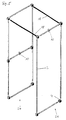
- Fig. 2 shows an exploded view of a connecting element 4 and the ends of two tubular elements 2 with corresponding Connectors 6.
- the connector 4 has four bores 8, 12. Two of the holes 8, which designed in the present example as the larger holes 8 are used to accommodate the connectors 6 the tubular elements 2.
- the smaller holes 12 are with provided with an internal thread and for receiving screws 14 designed. Now becomes a pipe element 2 with its connector 6 in the corresponding bore 8 of the connecting element 4 introduced, the tubular element 2 or the connector 6 from the side through the clamping Effect of the corresponding screw 14 can be set. This is for the stated purpose in the corresponding Drilled hole 12. Run in the example the tips of the screws 14 at an angle of approximately 90 ° conical out.
- FIG. 4 is a third embodiment of the invention illustrated.
- the metallic pipe elements 2 and the connecting elements 4 arranged so that the compensating Configuration of an "eight" is realized.
- a toroid can also be used in this embodiment suitable location of a pipe element 2 of the pipe system be placed. Even with this special arrangement the same connecting elements 4 can be used as in the other Embodiments of the invention.
- FIG. 5 A fourth embodiment of the invention is in FIG. 5 shown. Again, two sides 24, 26 are the gate probe electrically isolated from each other by plastic tubes 18. On the metallic tubular elements 2 are ring cores 10 for each side 24, 26 of the gate probe is arranged. It is of course, any similar arrangement of toroidal cores 10, which is generally simply over the tubular elements 2 can be pushed, conceivable.
- FIG. 6 shows a further variant of the arrangement of tubular elements 2, connecting elements 4, plastic tube elements 18 and a ring core 10.
- the ring core 10 is over here a tubular element 2 is pushed in the head part of the door probe.
- FIG. 7 A sixth embodiment of the present invention is shown in Fig. 7.
- the gate probe is through again Plastic tubes 18 divided into two sides 28, 30.
- the Right side 30 of the door probe is through again shorter plastic pipes 32 in two insulated from each other Sections 34, 36 divided.
- Each of sections 28, 34, 36 each carries a ring core 10.
- the present arrangement is preferably operated so that the section 28 is used as a transmitter, while sections 34 and 36 can be interconnected for reception in opposite phases. To this The transmission signal can be compensated in this way.
- This too Arrangement is in terms of the send and receive characteristics reversible.
Landscapes
- Remote Sensing (AREA)
- Engineering & Computer Science (AREA)
- Life Sciences & Earth Sciences (AREA)
- Physics & Mathematics (AREA)
- Geology (AREA)
- Environmental & Geological Engineering (AREA)
- Electromagnetism (AREA)
- General Life Sciences & Earth Sciences (AREA)
- General Physics & Mathematics (AREA)
- Geophysics (AREA)
- Geophysics And Detection Of Objects (AREA)
- Transition And Organic Metals Composition Catalysts For Addition Polymerization (AREA)
- Prostheses (AREA)
- Materials For Medical Uses (AREA)
Abstract
Description
Die Erfindung betrifft eine Torsonde mit mindestens einem Sender, welcher ein Magnetfeld erzeugt, und mindestens einem Empfänger, wobei die Anwesenheit metallischer Gegenstände über eine Veränderung des Magnetfeldes nachweisbar ist.The invention relates to a door probe with at least one Transmitter that generates a magnetic field, and at least a receiver, the presence of metallic objects detectable by a change in the magnetic field is.
In der US-A-4,605,898 ist eine gattungsgemäße Vorrichtung beschrieben. Sowohl der Sender als auch der Empfänger sind als Spulensystem verwirklicht und in einer speziellen Weise angeordnet. Die Spulen werden von einem Rahmen getragen. Ferner sind sie durch Schutzplatten gegen einen Zugriff von außen geschützt. Der Rahmen sowie die Schutzplatten bilden das eigentliche Tor, so daß Gegenstände, welche durch das Tor hindurchgeführt werden, durch die von dem Rahmen getragenen Spulen nachgewiesen werden können.In US-A-4,605,898 is a generic device described. Both the sender and the receiver are realized as a coil system and in a special way arranged. The coils are carried by a frame. Furthermore, they are protected against access by protective plates protected outside. Form the frame and the protective plates the actual gate, so that objects, which by the Be guided through, carried by the frame Coils can be detected.
Bei derartigen Torsonden besteht ein wesentlicher Kostenfaktor im äußeren Aufbau, d.h. - bezogen auf das beschriebene Beispiel - in der Notwendigkeit eines Rahmens sowie der genannten Schutzplatten. Damit ist auch verbunden, daß eine Herstellung der gattungsgemäßen Torsonden "aus einer Hand" in der Regel nicht möglich sein wird, da elektronisch bzw. elektromechanisch orientierte Unternehmen in der Regel über keine Erfahrungen im Bereich der Holz- oder Kunststoffverarbeitung verfügen. Die Rahmen- und Schutzkonstruktionen sind aber in der Regel aus solchen Materialien aufgebaut. With such gate probes there is an essential cost factor in the outer structure, i.e. - based on the described Example - in need of a framework as well of the protective plates mentioned. This also means that a production of the generic gate probes "from a Hand "will generally not be possible because it is electronic or electro-mechanically oriented companies as a rule no experience in the field of wood or plastic processing feature. The frame and protective structures but are usually made of such materials.
Ähnlich verhält es sich in verwandten technischen Bereichen, wie aus der DE 195 03 896 A1 ersichtlich ist. Die dort offenbarte Vorrichtung betrifft die Detektion eines mit einem elektronischen Sicherungselement versehenen Artikels in einer Überwachungszone, etwa im Ausgangsbereich eines Warenhauses. Auch hier sind die Detektionsspulen in einem sog. Gatter angeordnet, was die oben beschriebenen Kostennachteile sowie die Schwierigkeiten bei der Fertigung der Vorrichtung mit sich bringt.The situation is similar in related technical areas, as can be seen from DE 195 03 896 A1. The The device disclosed there relates to the detection of a article provided with an electronic security element in a surveillance zone, for example in the exit area of a department store. The detection coils are also in here a so-called. Gate arranged what the above described Cost disadvantages and the difficulties in manufacturing of the device.
Der Erfindung liegt somit die Aufgabe zugrunde, die genannten Nachteile zu beseitigen; insbesondere soll ein kostengünstiges, gut handhabbares System zur Verfügung gestellt werden, welches durch einheitliche Fertigungstechniken herstellbar ist.The invention is therefore based on the object of eliminating the disadvantages mentioned; in particular, a cost-effective, easy-to-use system is to be made available, which can be produced using uniform manufacturing techniques.
Diese Aufgabe wird mit den Merkmalen von Anspruch 1 gelöst.This object is achieved with the features of claim 1.
Danach ist die gattungsgemäße Vorrichtung dadurch weitergebildet, daß der Sender und/oder der Empfänger als im wesentlichen selbsttragende Metallkonstruktion ausgebildet ist/sind. Damit ist die Funktion der Sende- bzw. Empfangsspulen sowie des Tragerahmens bzw. von Schutzabdeckungen in integrierter Form realisiert. Die Metallkonstruktion bietet die erforderlichen Sende- und Empfangsfunktionen und kann gleichzeitig die notwendige mechanische Stabilität zur Verwendung als Torsonde ohne weitere Hilfsaufbauten aufbringen.Thereafter, the generic device is further developed that the transmitter and / or the receiver as essentially self-supporting metal construction is / are. This is the function of the transmitting or receiving coils as well as the support frame or protective covers in integrated form realized. The metal construction offers the required send and receive functions and can at the same time the necessary mechanical stability Apply as a gate probe without any additional superstructures.
Besonders vorteilhaft ist es, wenn die Metallkonstruktion zerlegbar ist. Durch diesen Umstand wird die Auslieferung sowie die Anlieferung der erfindungsgemäßen Torsonde erheblich erleichtert. Ferner senkt die Zerlegbarkeit und das dadurch bedingte verringerte Packmaß die Lagerkosten. Aufgrund der Zerlegbarkeit ist es weiterhin denkbar, daß die Torsonde an wechselnden Einsatzorten Verwendung findet; insbesondere in der heutigen Zeit ist es bei den verschiedensten Veranstaltungen zunehmend erforderlich, strenge Sicherheitsvorkehrungen, beispielsweise gegen Kriminalität und Terrorismus, zu treffen.It is particularly advantageous if the metal construction can be dismantled. Due to this fact, the delivery and the delivery of the gate probe according to the invention considerably facilitated. Furthermore, the dismantling lowers and that this resulted in a reduced pack size for storage costs. Because of the dismantling, it is also conceivable that the Gate probe is used in changing locations; especially in today's time it is with the most diverse Events increasingly required, strict security precautions, for example against crime and terrorism.
Vorteilhafterweise ist auf die Metallkonstruktion mindestens ein Ringkern aufgesetzt. Mit einem solchen Ringkern, welcher über eine Wicklung verfügt, wird die Metallkonstruktion besendet. Ebenfalls kann das empfangene Signal über den Ringkern an der Metallkonstruktion abgenommen werden. Es kann ein einzelner Ringkern vorgesehen sein, welcher sowohl die Sendefunktion als auch, über die Impedanzänderung des Rahmens, die Empfangsfunktion vermittelt. Ebenfalls können unter Verwendung mehrerer Ringkerne Sende- und Empfangsfunktionen voneinander getrennt werden.Advantageously, at least on the metal structure a toroid is put on. With such a toroid which has a winding becomes the metal construction sent. The received signal can also can be removed via the toroid on the metal construction. A single toroidal core can be provided, which both the transmit function and, via the change in impedance of the frame that conveys the reception function. You can also transmit and use multiple ring cores Receive functions are separated from each other.
Bevorzugt weist die Metallkonstruktion einzelne Rohrelemente auf. Damit ist ein stabiler und schneller Aufbau der Metallkonstruktion möglich. Ferner sind Metallrohre kostengünstig und in praktisch beliebigen Ausführungen auf dem Markt erhältlich. Es sind Rundrohre, Vierkantrohre oder auch beliebige andere Metallprofile zum Herbeiführen der erfindungsgemäßen Vorteile einsetzbar.The metal construction preferably has individual tubular elements on. So that a stable and fast construction of the Metal construction possible. Furthermore, metal pipes are inexpensive and in practically any version on the Market available. There are round tubes, square tubes or also any other metal profiles to bring about the Advantages of the invention can be used.
Vorzugsweise weist die Metallkonstruktion einzelne mechanische Verbindungselemente auf. Damit können die den Rahmen bildenden Elemente, beispielsweise die Rohrelemente, in zuverlässiger Weise miteinander verbunden werden. Es wird ein modularer und damit variabler Aufbau der Torsonde ermöglicht.The metal construction preferably has individual mechanical ones Fasteners. So that the frame forming elements, such as the pipe elements, in more reliable Way to be connected. It will be a modular and thus variable structure of the door probe enables.
Besonders vorteilhaft ist es, wenn die Verbindungselemente elektrisch leitfähig sind. Durch diesen Umstand bieten die Verbindungselemente neben der mechanischen Verbindung gleichzeitig die elektrische Verbindung der Konstruktionselemente, so daß die erforderliche Sende- bzw. Empfangsinduktivität zur Verfügung gestellt wird.It is particularly advantageous if the connecting elements are electrically conductive. Because of this, the Fasteners in addition to the mechanical connection at the same time the electrical connection of the construction elements, so that the required transmission or reception inductance is made available.
Bevorzugt sind die Rohrelemente endseitig mit Verbindungsstücken versehen, über welche sie mit den Verbindungselementen verbunden sind. Diese Verbindungsstücke, welche beispielsweise aus Aluminium-Vollmaterial gefertigt sind, bieten die Möglichkeit, die Rohre an die Gestalt der Verbindungselemente anzupassen.The tubular elements are preferably end-to-end with connecting pieces provided, via which they with the connecting elements are connected. These connectors, which for example are made of solid aluminum material the ability to match the pipes to the shape of the fasteners adapt.
Das Vorsehen der Verbindungsstücke ist besonders vorteilhaft, wenn diese über eine Schraubklemmung mit den Verbindungselementen verbunden sind. Beispielsweise werden die Verbindungsstücke in Löcher, welche in den Verbindungselementen vorgesehen sind, eingeführt, und eine Schraube wird senkrecht zur Lochachse zur Verklemmung der Verbindungsstücke in das entsprechende Verbindungselement eingeschraubt.The provision of the connecting pieces is particularly advantageous if this has a screw clamp with the connecting elements are connected. For example, the Connectors in holes that are in the connectors are provided, and a screw is inserted perpendicular to the hole axis for jamming the connecting pieces screwed into the corresponding connecting element.
Dabei weisen die Verbindungsstücke bevorzugt eine Senkung zur verdrehsicheren Schraubklemmung auf. Die Senkung, in welche die klemmende Schraube kraft- und/oder formschlüssig eingreifen sollte, verhindert einerseits das unbeabsichtigte Austreten des Verbindungsstückes aus dem Verbindungselement, gibt weiterhin einen verdrehsicheren Halt und definiert ferner die exakte Position des Verbindungsstückes und damit des Elementes der Metallkonstruktion im Verbindungselement.The connecting pieces preferably have a countersink for twist-proof screw clamping. The lowering, in which the clamping screw non-positively and / or positively should intervene, on the one hand prevents the unintentional Emergence of the connecting piece from the connecting element, still gives a twist-proof hold and defines also the exact position of the connector and thus the element of the metal structure in the connecting element.
Ebenfalls kann dabei besonders vorteilhaft sein, wenn die Verbindungsstücke eine Nut aufweisen, in welche die Schraubklemmung eingreift. Wenn diese Nut als um das zylindrische Verbindungsstück umlaufende Nut ausgebildet ist, so erleichtert dies die Montage der Torsonde, da das Rohr in beliebig gedrehter Position in dem Verbindungselement festsetzbar ist. Die Sicherung des Rohres gegen das unbeabsichtigte Herausrutschen aus dem Verbindungselement sowie die exakte Positionsfestlegung sind durch die Nut ebenfalls gewährleistet.It can also be particularly advantageous if the Connectors have a groove in which the Screw clamp engages. If this groove than around the cylindrical Connector circumferential groove is formed, so This facilitates the assembly of the gate probe, since the tube in arbitrarily rotated position in the connecting element fixable is. Securing the pipe against accidental Slipping out of the connecting element as well as the exact positioning is also guaranteed by the groove.
Bevorzugt ist die Impedanz der durch die Metallkonstruktion bereitgestellten Induktivität durch in der Umgebung der Metallkonstruktion vorhandene Metallobjekte veränderbar. Durch Realisierung dieses bewährten Meßprinzips kann die Torsonde zuverlässig arbeiten und somit die erforderliche Sicherheit garantieren.The impedance of the metal structure is preferred provided inductance by in the vicinity of the Metal structure changeable existing metal objects. By implementing this proven measuring principle, the Torsonde work reliably and therefore the required Guarantee security.
Es kann vorteilhaft sein, wenn Empfänger und Sender symmetrisch aufgebaut sind. Ein solcher symmetrischer Aufbau kann durch die Umkehrbarkeit des Systems realisiert werden. Mit anderen Worten: der Sender kann ebenfalls als Empfänger arbeiten und umgekehrt.It can be advantageous if the receiver and transmitter are symmetrical are built up. Such a symmetrical structure can be realized by the reversibility of the system. In other words, the transmitter can also be used as Receiver work and vice versa.
Bevorzugt sind die Induktionsänderungen des Senders und des Empfängers auswertbar, und man hat somit zwei Signale zur Verfügung. Folglich erreicht man eine Verbesserung der Meßgenauigkeit.The induction changes of the transmitter and of the Receiver can be evaluated, and you thus have two signals Available. As a result, the measurement accuracy is improved.
Vorzugsweise ist in diesem Zusammenhang zur Verarbeitung der aus den Induktionsänderungen resultierenden Signale eine Differenzstufe vorgesehen. Auf diese Weise können Störamplituden, die entgegengesetzt gleich auf die Meßeingänge der Differenzstufe einwirken, in weiten Grenzen eliminiert werden.In this context, processing is preferred the signals resulting from the changes in induction a difference level is provided. That way you can Interference amplitudes that are opposite the same on the measurement inputs the difference level act within wide limits be eliminated.
Bevorzugt besteht die Metallkonstruktion aus Aluminium. Damit weist sie eine ausreichende Leitfähigkeit auf; ferner ist Aluminium als Leichtmetall beim Transport als auch beim Aufbau der Konstruktion vorteilhaft. The metal construction is preferably made of aluminum. In order to it has sufficient conductivity; further is aluminum as a light metal for transport as well as for Structure of the construction advantageous.
Der/die Ringkern(e) ist/sind bevorzugt sinus- oder pulsförmig erregbar. Beide dieser bekannten Detektionsverfahren sind im Rahmen der Erfindung in vorteilhafter Weise einsetzbar.The ring core (s) is / are preferably sinusoidal or pulse-shaped excitable. Both of these known detection methods can be used advantageously in the context of the invention.
Besonders vorteilhaft kann sein, wenn die Metallkonstruktion die Konfiguration einer "Acht" aufweist. Eine derartige Anordnung hat eine kompensierende Wirkung, da die Amplituden der Störsignale dann entgegengesetzt gleichwirkend sind und sich auf diese Weise zum großen Teil aufheben.It can be particularly advantageous if the metal construction has the configuration of an "eight". Such Arrangement has a compensating effect because of the amplitudes the interference signals then have the opposite effect are and largely cancel each other out in this way.
Die Metallkonstruktion kann vorzugsweise Kunststoffrohrelemente aufweisen. Dies ist nützlich, wenn beispielsweise eine Isolierung zwischen der Sender- und der Empfängerseite erwünscht ist.The metal construction can preferably be plastic pipe elements exhibit. This is useful if, for example insulation between the transmitter and receiver side is desired.
Der Erfindung liegt die überraschende Erkenntnis zugrunde, daß durch die Ausbildung einer Torsonde als selbsttragende Metallkonstruktion eine kostengünstige und den praktischen Bedürfnissen angepaßte, überaus wirkungsvolle Lösung bereitgestellt ist. Es entfallen die Nachteile einer aufwendigen Trag- und Schutzkonstruktion für die Sende- bzw. Empfangsspulen. Durch die vorteilhafte Zerlegbarkeit und den Aufbau durch Rohre und Verbindungselemente steht ein modulares System zur Verfügung, welches variabel und allenorts einsetzbar ist.The invention is based on the surprising finding that by forming a gate probe as a self-supporting Metal structure an inexpensive and practical Customized, extremely effective solution is provided. There are no disadvantages of a complex Support and protection structure for the transmission or Receiving coils. Due to the advantageous dismantling and the construction by means of pipes and connecting elements is guaranteed modular system available, which is variable and everywhere can be used.
Die vorliegende Erfindung wird nun beispielhaft mit Bezug auf die begleitenden Zeichnungen anhand bevorzugter Ausführungsformen beschrieben. Dabei zeigt:
- Fig. 1
- eine Explosionsdarstellung einer ersten Ausführungsform der vorliegenden Erfindung;
- Fig. 2
- eine Explosionsdarstellung zur Erläuterung der Funktion eines Verbindungselementes;
- Fig. 3
- eine Explosionsdarstellung einer zweiten Ausführungsform der Erfindung;
- Fig. 4
- eine Explosionsdarstellung einer dritten Ausführungsform der Erfindung;
- Fig. 5
- eine Explosionsdarstellung einer vierten Ausführungsform der Erfindung;
- Fig. 6
- eine Explosionsdarstellung einer fünften Ausführungsform der Erfindung; und
- Fig. 7
- eine Explosionsdarstellung einer sechsten Ausführungsform der Erfindung.
- Fig. 1
- an exploded view of a first embodiment of the present invention;
- Fig. 2
- an exploded view to explain the function of a connecting element;
- Fig. 3
- an exploded view of a second embodiment of the invention;
- Fig. 4
- an exploded view of a third embodiment of the invention;
- Fig. 5
- an exploded view of a fourth embodiment of the invention;
- Fig. 6
- an exploded view of a fifth embodiment of the invention; and
- Fig. 7
- an exploded view of a sixth embodiment of the invention.
Fig. 1 zeigt den Aubau einer Torsonde, welche aus Rohrelementen
2 zusammengesetzt ist. Die Rohrelemente 2 sind über
Verbindungselemente 4 miteinander zu verbinden. Endseitig
weisen die Rohrelemente 2 Verbindungsstücke 6 auf, über
welche sie mit den Verbindungselementen 4 verbunden werden
können. Zu diesem Zweck sind in den Verbindungselementen 4
zylindrische Löcher 8 vorgesehen. Eines der Rohrelemente 2
trägt einen Ringkern 10 aus Eisen zum Besenden des Rahmens.Fig. 1 shows the construction of a door probe, which consists of
Mit dieser Anordnung kann die erfindungsgemäße Torsonde
nach dem Dämpfungsprinzip arbeiten. Der Ringkern 10 ist Bestandteil
eines Oszillatorschwingkreises, der in das aus den
Rohrelementen 2 bestehende Rohrsystem einen Strom induziert.
Der metallische Rahmen wirkt als Induktivität, deren
Impedanz sich durch Metallobjekte, die durch den Rahmen
geführt werden, verändert. Die somit entstehende Amplitudenänderung
kann als Signalwert aufgenommen und beispielsweise
zu einem Alarmton umgesetzt werden. With this arrangement, the door probe according to the invention
work according to the damping principle. The
Fig. 2 zeigt in Explosionsdarstellung ein Verbindungselement
4 sowie die Enden zweier Rohrelemente 2 mit entsprechenden
Verbindungsstücken 6. Das Verbindungselement 4
weist vier Bohrungen 8, 12 auf. Zwei der Bohrungen 8, welche
im vorliegenden Beispiel als die größeren Bohrungen 8 ausgelegt
sind, dienen der Aufnahme der Verbindungsstücke 6
der Rohrelemente 2. Die kleineren Bohrungen 12 sind mit
einem Innengewinde versehen und zur Aufnahme von Schrauben
14 ausgelegt. Wird nun ein Rohrelement 2 mit seinem Verbindungsstück
6 in die entsprechende Bohrung 8 des Verbindungselements
4 eingeführt, so kann das Rohrelement 2 bzw.
das Verbindungsstück 6 von der Seite durch die klemmende
Wirkung der entsprechenden Schraube 14 festgelegt werden.
Diese wird zu dem genannten Zweck in das entsprechende
Bohrloch 12 eingeschraubt. Im vorliegenden Beispiel laufen
die Spitzen der Schrauben 14 in einem Winkel von ca. 90°
kegelig aus. Auf diese Weise finden sie einen form- und/oder
kraftschlüssigen Sitz in der entsprechend ausgebildeten
Senkung 16 in den Verbindungsstücken 6 der Rohrelemente
2. Die Rohrelemente 2 bzw. die Verbindungsstücke 6 sind auf
diese Weise gegen Herausrutschen aus den Verbindungselementen
4 und ferner gegen Verdrehung in den Bohrungen 8 gesichert.Fig. 2 shows an exploded view of a connecting
In einer weiteren, hier nicht dargestellten Ausführungsform
kann anstelle der Senkung 16 - oder auch zusätzlich an
einer anderen Stelle des Verbindungsstückes 6 - eine zumindest
teilweise umlaufende Nut vorgesehen sein. Dies erleichtert
den Zusammenbau von Rohrelementen 2 und Verbindungselementen
4, da nicht mehr auf die relative Drehung
der Rohrelemente geachtet werden muß. Eine Sicherung gegen
Herausrutschen wird von den Nuten gleichwohl bereitgestellt. In a further embodiment, not shown here
can instead of 16 - or in addition
another point of the connector 6 - at least one
partially circumferential groove may be provided. This makes it easier
the assembly of
Selbstverständlich kann unter Umständen auch auf die an den
Rohrelementen 2 endseitig vorgesehenen Verbindungsstücke 6
verzichtet werden. Die Rohrelemente 2 werden dann direkt in
den Verbindungselementen 4 eingeklemmt.Of course, under certain circumstances can also be addressed to the
Besonders zu erwähnen ist, daß durch die vorgeschlagene
Konstruktion der Verbindungselemente 4 eine ausreichend
leitfähige Verbindung zwischen den Rohrelementen 2 ermöglicht
werden kann, so daß ein funktionsfähiges Sondensystem
verwirklicht ist.It is particularly worth mentioning that the proposed
Construction of the connecting elements 4 a sufficient
Conductive connection between the
Anhand von Fig. 3 wird eine zweite Ausführungsform der Erfindung
erläutert. Neben den aus Metall bestehenden Rohrelementen
2 sind im Kopfbereich der Torsonde Kunststoffrohre
18 vorgesehen. Diese sind elektrisch isolierend, so
daß jede Seite 20, 22 der Torsonde, welche jeweils mit
einem Ringkern 10 bestückt ist, als separater, elektrisch
geschlossener Sende- und Empfangskreis arbeitet.
Weiterhin sind in der Darstellung der Fig. 3 wiederum die
Verbindungselemente 4 dargestellt.3, a second embodiment of the invention
explained. In addition to the
In Fig. 4 ist eine dritte Ausführungsform der Erfindung
veranschaulicht. Hier sind die metallischen Rohrelemente 2
und die Verbindungselemente 4 so angeordnet, daß die kompensierende
Konfiguration einer "Acht" realisiert ist. Die
Amplituden von Störsignalen wirken auf diese Weise entgegengesetzt
gleich und heben sich damit zu großen Teil auf.
Ein Ringkern kann auch bei diesem Ausführungsbeispiel an
geeigneter Stelle eines Rohrelementes 2 des Rohrsystems
plaziert werden. Auch bei dieser speziellen Anordnung sind
dieselben Verbindungselemente 4 einsetzbar wie bei den anderen
Ausführungsformen der Erfindung. 4 is a third embodiment of the invention
illustrated. Here are the
Eine vierte Ausführungsform der Erfindung ist in Fig. 5
dargestellt. Wiederum sind zwei Seiten 24, 26 der Torsonde
durch Kunststoffrohre 18 elektrisch gegeneinander isoliert.
Auf den metallischen Rohrelementen 2 sind Ringkerne 10 für
jede Seite 24, 26 der Torsonde angeordnet. Dabei ist
selbstverständlich jede ähnliche Anordnung von Ringkernen
10, welche im allgemeinen schlicht über die Rohrelemente
2 geschoben werden, denkbar.A fourth embodiment of the invention is in FIG. 5
shown. Again, two
Fig. 6 zeigt eine weitere Variante der Anordnung von Rohrelementen
2, Verbindungselementen 4, Kunststoffrohrelementen
18 und einem Ringkern 10. Der Ringkern 10 ist hier über
ein Rohrelement 2 im Kopfteil der Torsonde geschoben.6 shows a further variant of the arrangement of
Eine sechste Ausführungsform der vorliegenden Erfindung ist
in Fig. 7 dargestellt. Die Torsonde ist wiederum durch
Kunststoffrohre 18 in zwei Seiten 28, 30 unterteilt. Die
rechte Seite 30 der Torsonde ist dabei nochmals durch
kürzere Kunststoffrohre 32 in zwei gegeneinander isolierte
Abschnitte 34, 36 aufgeteilt. Jeder der Abschnitte 28, 34,
36 trägt je einen Ringkern 10. Mit der vorliegenden Anordnung
wird vorzugsweise so verfahren, daß der Abschnitt 28
als Sender verwendet wird, während die Abschnitte 34 und 36
zum gegenphasigen Empfang verschaltet werden. Auf diese
Weise kann das Sendesignal kompensiert werden. Auch diese
Anordnung ist im Hinblick auf die Sende- und Empfangseigenschaft
umkehrbar.A sixth embodiment of the present invention is
shown in Fig. 7. The gate probe is through again
Die in der vorstehenden Beschreibung, in den Zeichnungen sowie in den Ansprüchen offenbarten Merkmale der Erfindung können sowohl einzeln als auch in beliebiger Kombination für die Verwirklichung der Erfindung wesentlich sein.The in the above description, in the drawings as well as features of the invention disclosed in the claims can be used individually or in any combination be essential for the implementation of the invention.
Claims (15)
dadurch gekennzeichnet,
characterized by
dadurch gekennzeichnet,
daß die Metallkonstruktion (2, 4, 6, 8) zerlegbar ist und einzelne Rohrelemente (2) aufweist.Torsonde according to claim 1,
characterized by
that the metal structure (2, 4, 6, 8) can be dismantled and has individual tubular elements (2).
dadurch gekennzeichnet,
daß auf die Metallkonstruktion (2, 4, 6, 8) mindestens ein Ringkern (10) aufgesetzt ist.Torsonde according to claim 1 or 2,
characterized by
that at least one ring core (10) is placed on the metal structure (2, 4, 6, 8).
dadurch gekennzeichnet,
daß die Metallkonstruktion (2, 4, 6, 8) einzelne elektrisch leitfähige, mechanische Verbindungselemente (4) aufweist. Torsonde according to one of claims 1 to 3,
characterized by
that the metal structure (2, 4, 6, 8) has individual electrically conductive, mechanical connecting elements (4).
dadurch gekennzeichnet,
daß die Rohrelemente (2) endseitig mit Verbindungsstücken (6) versehen sind, über welche sie mit den Verbindungselementen (4) über eine Schraubklemmung (12, 14) verbunden sind.Torsonde according to claim 4,
characterized by
that the tubular elements (2) are provided at the end with connecting pieces (6), by means of which they are connected to the connecting elements (4) via a screw clamp (12, 14).
dadurch gekennzeichnet,
daß die Verbindungsstücke (6) eine Senkung (16) zur verdrehsicheren Schraubklemmung aufweisen.Torsonde according to claim 5,
characterized by
that the connecting pieces (6) have a counterbore (16) for twist-proof screw clamping.
dadurch gekennzeichnet,
daß die Verbindungsstücke (6) eine Nut aufweisen, in welche die Schraubklemmung eingreift.Torsonde according to one of claims 5 or 6,
characterized by
that the connecting pieces (6) have a groove in which the screw clamp engages.
dadurch gekennzeichnet,
daß die Impedanz der durch die Metallkonstruktion (2, 4, 6, 8) bereitgestellten Induktivität durch in der Umgebung der Metallkonstruktion (2, 4, 6, 8) vorhandene Metallobjekte veränderbar ist.Torsonde according to one of the preceding claims,
characterized by
that the impedance of the inductance provided by the metal structure (2, 4, 6, 8) can be changed by metal objects present in the surroundings of the metal structure (2, 4, 6, 8).
dadurch gekennzeichnet,
daß Empfänger und Sender symmetrisch aufgebaut sind.Torsonde according to one of the preceding claims,
characterized by
that the receiver and transmitter are constructed symmetrically.
dadurch gekennzeichnet,
daß die Induktionsänderungen des Senders und des Empfängers auswertbar sind, wobei zur Verarbeitung der aus den Induktionsänderungen resultierenden Signale eine Differenzstufe vorgesehen ist. Torsonde according to one of the preceding claims,
characterized by
that the changes in the induction of the transmitter and the receiver can be evaluated, a difference stage being provided for processing the signals resulting from the changes in the induction.
dadurch gekennzeichnet,
daß die Metallkonstruktion (2, 4, 6, 8) aus Aluminium besteht.Torsonde according to one of the preceding claims,
characterized by
that the metal structure (2, 4, 6, 8) consists of aluminum.
dadurch gekennzeichnet,
daß der/die Ringkern(e) sinusförmig erregbar ist/sind.Torsonde according to one of claims 3 to 11,
characterized by
that the ring core (s) can be excited sinusoidally.
dadurch gekennzeichnet,
daß der/die Ringkern(e) pulsförmig erregbar ist/sind.Torsonde according to one of claims 3 to 11,
characterized by
that the toroid (s) can be excited in a pulsed manner.
dadurch gekennzeichnet,
daß die Metallkonstruktion (2, 4, 6, 8) die Konfiguration einer "Acht" aufweist.Torsonde according to one of the preceding claims,
characterized by
that the metal structure (2, 4, 6, 8) has the configuration of an "eight".
dadurch gekennzeichnet,
daß die Metallkonstruktion (2, 4, 6, 8) Kunststoffrohrelemente (18, 32) aufweist.Torsonde according to one of the preceding claims,
characterized by
that the metal structure (2, 4, 6, 8) has plastic tube elements (18, 32).
Applications Claiming Priority (2)
| Application Number | Priority Date | Filing Date | Title |
|---|---|---|---|
| DE19858714 | 1998-12-18 | ||
| DE19858714A DE19858714A1 (en) | 1998-12-18 | 1998-12-18 | Gate probe |
Publications (3)
| Publication Number | Publication Date |
|---|---|
| EP1010991A2 true EP1010991A2 (en) | 2000-06-21 |
| EP1010991A3 EP1010991A3 (en) | 2003-03-19 |
| EP1010991B1 EP1010991B1 (en) | 2006-09-27 |
Family
ID=7891732
Family Applications (1)
| Application Number | Title | Priority Date | Filing Date |
|---|---|---|---|
| EP99122594A Expired - Lifetime EP1010991B1 (en) | 1998-12-18 | 1999-11-12 | Gate detector |
Country Status (4)
| Country | Link |
|---|---|
| EP (1) | EP1010991B1 (en) |
| AT (1) | ATE341008T1 (en) |
| DE (2) | DE19858714A1 (en) |
| ES (1) | ES2272032T3 (en) |
Families Citing this family (1)
| Publication number | Priority date | Publication date | Assignee | Title |
|---|---|---|---|---|
| US9424724B2 (en) * | 2013-08-02 | 2016-08-23 | Bibliotheca Rfid Library Systems Ag | Single turn magnetic drive loop for electronic article surveillance |
Citations (2)
| Publication number | Priority date | Publication date | Assignee | Title |
|---|---|---|---|---|
| US4605898A (en) | 1981-11-06 | 1986-08-12 | Outokumpu Oy | Pulse field metal detector with spaced, dual coil transmitter and receiver systems |
| DE19503896A1 (en) | 1995-02-07 | 1996-08-08 | Esselte Meto Int Gmbh | Device for detecting an article provided with an electronic security element |
Family Cites Families (6)
| Publication number | Priority date | Publication date | Assignee | Title |
|---|---|---|---|---|
| US605898A (en) * | 1898-06-21 | Composition of matter for plastering | ||
| DE1623104B2 (en) * | 1967-06-23 | 1974-09-12 | Clamann & Grahnert, X 8016 Dresden | Coil system for metal detector |
| US4016553A (en) * | 1975-06-27 | 1977-04-05 | Knogo Corporation | Article detection system with near field electromagnetic wave control |
| FR2553523B1 (en) * | 1983-10-17 | 1986-06-13 | Raibaud Guy | INDUCTIVE THEFT PROTECTION ALARM BY DETECTION OF RESONANT CIRCUITS |
| FR2619454B1 (en) * | 1987-08-14 | 1990-06-29 | Automatisme Tech Avancees | METHODS AND GATES OR SAS TO DETECT THE PASSAGE OF METAL MASSES |
| DE29822602U1 (en) * | 1998-12-18 | 1999-02-18 | Ebinger Klaus Ing Fa | Gate probe |
-
1998
- 1998-12-18 DE DE19858714A patent/DE19858714A1/en not_active Withdrawn
-
1999
- 1999-11-12 DE DE59913878T patent/DE59913878D1/en not_active Expired - Fee Related
- 1999-11-12 EP EP99122594A patent/EP1010991B1/en not_active Expired - Lifetime
- 1999-11-12 AT AT99122594T patent/ATE341008T1/en not_active IP Right Cessation
- 1999-11-12 ES ES99122594T patent/ES2272032T3/en not_active Expired - Lifetime
Patent Citations (2)
| Publication number | Priority date | Publication date | Assignee | Title |
|---|---|---|---|---|
| US4605898A (en) | 1981-11-06 | 1986-08-12 | Outokumpu Oy | Pulse field metal detector with spaced, dual coil transmitter and receiver systems |
| DE19503896A1 (en) | 1995-02-07 | 1996-08-08 | Esselte Meto Int Gmbh | Device for detecting an article provided with an electronic security element |
Also Published As
| Publication number | Publication date |
|---|---|
| ES2272032T3 (en) | 2007-04-16 |
| DE19858714A1 (en) | 2000-06-21 |
| EP1010991B1 (en) | 2006-09-27 |
| DE59913878D1 (en) | 2006-11-09 |
| EP1010991A3 (en) | 2003-03-19 |
| ATE341008T1 (en) | 2006-10-15 |
Similar Documents
| Publication | Publication Date | Title |
|---|---|---|
| DE3936278C2 (en) | Metal detector device | |
| DE1648358A1 (en) | Method and device for the determination of discontinuities in electrically conductive materials | |
| EP1862767A2 (en) | Safety positioning sensor for cylinder, cylinders with such a positioning sensor | |
| WO2001036903A1 (en) | Measuring rope-path sensor | |
| EP2149784B1 (en) | Magnetic path sensor system | |
| DE102015115264B3 (en) | Centering device for a Rogowski coil, measuring device, power electronic device and a method for arranging a Rogowski coil | |
| DE10234960B4 (en) | Sensor according to the transit time principle with a detector unit for mechanical-elastic waves | |
| DE2758969C2 (en) | Circular cylindrical housing for a switchgear | |
| DE3904271A1 (en) | FERRITE CORE COUPLED BLOCK (SLAPPER) DETECTING DEVICE AND METHOD THEREFOR | |
| EP3931539B1 (en) | Torque sensor unit comprising a magnetic shield | |
| EP1010991B1 (en) | Gate detector | |
| DE3331462C2 (en) | ||
| DE2942847A1 (en) | MAGNETIC FIELD DIFFERENTIAL PROBE | |
| DE4013429C2 (en) | Voltage detector | |
| EP0936741B1 (en) | Inductive proximity switch with a preferably one-piece housing | |
| DE2506248C3 (en) | Eddy current testing device for the non-destructive testing of objects | |
| DE10258115B4 (en) | Broadband measuring module for current measurement at power electronics devices | |
| DE19516235C2 (en) | Connection arrangement | |
| DE2228088C2 (en) | Clamp for connecting at least two round or sector conductors with a screw-on bolt of a transformer | |
| EP1010990B1 (en) | Arrangement for generation and/or receiving a magnetic field | |
| DE19831894C2 (en) | Magnetic inductive flow meter | |
| DE3827758A1 (en) | Device for monitoring a predetermined current strength in at least one electrical conductor | |
| EP2315044B1 (en) | Difference magnetometer probe | |
| DE2110514C (en) | Locator for electrically conductive objects | |
| DE102008047960A1 (en) | Annular coil for use in inductive conductivity sensor utilized for measuring conductivity of liquid medium, has electrical conductor with two conductive strip sections, where current flow in one of sections is directed against component |
Legal Events
| Date | Code | Title | Description |
|---|---|---|---|
| PUAI | Public reference made under article 153(3) epc to a published international application that has entered the european phase |
Free format text: ORIGINAL CODE: 0009012 |
|
| AK | Designated contracting states |
Kind code of ref document: A2 Designated state(s): AT BE CH CY DE DK ES FI FR GB GR IE IT LI LU MC NL PT SE |
|
| AX | Request for extension of the european patent |
Free format text: AL;LT;LV;MK;RO;SI |
|
| PUAL | Search report despatched |
Free format text: ORIGINAL CODE: 0009013 |
|
| AK | Designated contracting states |
Kind code of ref document: A3 Designated state(s): AT BE CH CY DE DK ES FI FR GB GR IE IT LI LU MC NL PT SE |
|
| AX | Request for extension of the european patent |
Extension state: AL LT LV MK RO SI |
|
| 17P | Request for examination filed |
Effective date: 20030519 |
|
| AKX | Designation fees paid |
Designated state(s): AT BE CH CY DE DK ES FI FR GB GR IE IT LI LU MC NL PT SE |
|
| GRAP | Despatch of communication of intention to grant a patent |
Free format text: ORIGINAL CODE: EPIDOSNIGR1 |
|
| GRAS | Grant fee paid |
Free format text: ORIGINAL CODE: EPIDOSNIGR3 |
|
| GRAA | (expected) grant |
Free format text: ORIGINAL CODE: 0009210 |
|
| AK | Designated contracting states |
Kind code of ref document: B1 Designated state(s): AT BE CH CY DE DK ES FI FR GB GR IE IT LI LU MC NL PT SE |
|
| PG25 | Lapsed in a contracting state [announced via postgrant information from national office to epo] |
Ref country code: NL Free format text: LAPSE BECAUSE OF FAILURE TO SUBMIT A TRANSLATION OF THE DESCRIPTION OR TO PAY THE FEE WITHIN THE PRESCRIBED TIME-LIMIT Effective date: 20060927 Ref country code: IT Free format text: LAPSE BECAUSE OF FAILURE TO SUBMIT A TRANSLATION OF THE DESCRIPTION OR TO PAY THE FEE WITHIN THE PRE;WARNING: LAPSES OF ITALIAN PATENTS WITH EFFECTIVE DATE BEFORE 2007 MAY HAVE OCCURRED AT ANY TIME BEFORE 2007. THE CORRECT EFFECTIVE DATE MAY BE DIFFERENT FROM THE ONE RECORDED.SCRIBED TIME-LIMIT Effective date: 20060927 Ref country code: IE Free format text: LAPSE BECAUSE OF FAILURE TO SUBMIT A TRANSLATION OF THE DESCRIPTION OR TO PAY THE FEE WITHIN THE PRESCRIBED TIME-LIMIT Effective date: 20060927 Ref country code: FI Free format text: LAPSE BECAUSE OF FAILURE TO SUBMIT A TRANSLATION OF THE DESCRIPTION OR TO PAY THE FEE WITHIN THE PRESCRIBED TIME-LIMIT Effective date: 20060927 |
|
| REG | Reference to a national code |
Ref country code: GB Ref legal event code: FG4D Free format text: NOT ENGLISH |
|
| REG | Reference to a national code |
Ref country code: CH Ref legal event code: EP |
|
| REG | Reference to a national code |
Ref country code: IE Ref legal event code: FG4D Free format text: LANGUAGE OF EP DOCUMENT: GERMAN |
|
| REF | Corresponds to: |
Ref document number: 59913878 Country of ref document: DE Date of ref document: 20061109 Kind code of ref document: P |
|
| PG25 | Lapsed in a contracting state [announced via postgrant information from national office to epo] |
Ref country code: MC Free format text: LAPSE BECAUSE OF NON-PAYMENT OF DUE FEES Effective date: 20061130 Ref country code: LI Free format text: LAPSE BECAUSE OF NON-PAYMENT OF DUE FEES Effective date: 20061130 Ref country code: CH Free format text: LAPSE BECAUSE OF NON-PAYMENT OF DUE FEES Effective date: 20061130 Ref country code: BE Free format text: LAPSE BECAUSE OF NON-PAYMENT OF DUE FEES Effective date: 20061130 |
|
| GBT | Gb: translation of ep patent filed (gb section 77(6)(a)/1977) |
Effective date: 20061127 |
|
| PG25 | Lapsed in a contracting state [announced via postgrant information from national office to epo] |
Ref country code: SE Free format text: LAPSE BECAUSE OF FAILURE TO SUBMIT A TRANSLATION OF THE DESCRIPTION OR TO PAY THE FEE WITHIN THE PRESCRIBED TIME-LIMIT Effective date: 20061227 Ref country code: DK Free format text: LAPSE BECAUSE OF FAILURE TO SUBMIT A TRANSLATION OF THE DESCRIPTION OR TO PAY THE FEE WITHIN THE PRESCRIBED TIME-LIMIT Effective date: 20061227 |
|
| NLV1 | Nl: lapsed or annulled due to failure to fulfill the requirements of art. 29p and 29m of the patents act | ||
| PG25 | Lapsed in a contracting state [announced via postgrant information from national office to epo] |
Ref country code: PT Free format text: LAPSE BECAUSE OF FAILURE TO SUBMIT A TRANSLATION OF THE DESCRIPTION OR TO PAY THE FEE WITHIN THE PRESCRIBED TIME-LIMIT Effective date: 20070313 |
|
| ET | Fr: translation filed | ||
| REG | Reference to a national code |
Ref country code: ES Ref legal event code: FG2A Ref document number: 2272032 Country of ref document: ES Kind code of ref document: T3 |
|
| REG | Reference to a national code |
Ref country code: IE Ref legal event code: FD4D |
|
| REG | Reference to a national code |
Ref country code: CH Ref legal event code: PL |
|
| PLBE | No opposition filed within time limit |
Free format text: ORIGINAL CODE: 0009261 |
|
| STAA | Information on the status of an ep patent application or granted ep patent |
Free format text: STATUS: NO OPPOSITION FILED WITHIN TIME LIMIT |
|
| 26N | No opposition filed |
Effective date: 20070628 |
|
| BERE | Be: lapsed |
Owner name: EBINGER, KLAUS Effective date: 20061130 |
|
| PG25 | Lapsed in a contracting state [announced via postgrant information from national office to epo] |
Ref country code: GR Free format text: LAPSE BECAUSE OF FAILURE TO SUBMIT A TRANSLATION OF THE DESCRIPTION OR TO PAY THE FEE WITHIN THE PRESCRIBED TIME-LIMIT Effective date: 20061228 |
|
| PG25 | Lapsed in a contracting state [announced via postgrant information from national office to epo] |
Ref country code: LU Free format text: LAPSE BECAUSE OF NON-PAYMENT OF DUE FEES Effective date: 20061112 |
|
| PG25 | Lapsed in a contracting state [announced via postgrant information from national office to epo] |
Ref country code: CY Free format text: LAPSE BECAUSE OF FAILURE TO SUBMIT A TRANSLATION OF THE DESCRIPTION OR TO PAY THE FEE WITHIN THE PRESCRIBED TIME-LIMIT Effective date: 20060927 |
|
| PGFP | Annual fee paid to national office [announced via postgrant information from national office to epo] |
Ref country code: DE Payment date: 20081126 Year of fee payment: 10 |
|
| PGFP | Annual fee paid to national office [announced via postgrant information from national office to epo] |
Ref country code: ES Payment date: 20081117 Year of fee payment: 10 Ref country code: AT Payment date: 20081124 Year of fee payment: 10 |
|
| PGFP | Annual fee paid to national office [announced via postgrant information from national office to epo] |
Ref country code: IT Payment date: 20081120 Year of fee payment: 10 |
|
| PGFP | Annual fee paid to national office [announced via postgrant information from national office to epo] |
Ref country code: FR Payment date: 20081030 Year of fee payment: 10 |
|
| PGFP | Annual fee paid to national office [announced via postgrant information from national office to epo] |
Ref country code: GB Payment date: 20081003 Year of fee payment: 10 |
|
| GBPC | Gb: european patent ceased through non-payment of renewal fee |
Effective date: 20091112 |
|
| REG | Reference to a national code |
Ref country code: FR Ref legal event code: ST Effective date: 20100730 |
|
| PG25 | Lapsed in a contracting state [announced via postgrant information from national office to epo] |
Ref country code: AT Free format text: LAPSE BECAUSE OF NON-PAYMENT OF DUE FEES Effective date: 20091112 |
|
| PG25 | Lapsed in a contracting state [announced via postgrant information from national office to epo] |
Ref country code: FR Free format text: LAPSE BECAUSE OF NON-PAYMENT OF DUE FEES Effective date: 20091130 |
|
| PG25 | Lapsed in a contracting state [announced via postgrant information from national office to epo] |
Ref country code: DE Free format text: LAPSE BECAUSE OF NON-PAYMENT OF DUE FEES Effective date: 20100601 |
|
| PG25 | Lapsed in a contracting state [announced via postgrant information from national office to epo] |
Ref country code: GB Free format text: LAPSE BECAUSE OF NON-PAYMENT OF DUE FEES Effective date: 20091112 |
|
| REG | Reference to a national code |
Ref country code: ES Ref legal event code: FD2A Effective date: 20110303 |
|
| PG25 | Lapsed in a contracting state [announced via postgrant information from national office to epo] |
Ref country code: IT Free format text: LAPSE BECAUSE OF NON-PAYMENT OF DUE FEES Effective date: 20091112 |
|
| PG25 | Lapsed in a contracting state [announced via postgrant information from national office to epo] |
Ref country code: ES Free format text: LAPSE BECAUSE OF NON-PAYMENT OF DUE FEES Effective date: 20110302 |
|
| PG25 | Lapsed in a contracting state [announced via postgrant information from national office to epo] |
Ref country code: ES Free format text: LAPSE BECAUSE OF NON-PAYMENT OF DUE FEES Effective date: 20091113 |