EP1007953B1 - Integrated microfluidic devices - Google Patents
Integrated microfluidic devices Download PDFInfo
- Publication number
- EP1007953B1 EP1007953B1 EP97937078A EP97937078A EP1007953B1 EP 1007953 B1 EP1007953 B1 EP 1007953B1 EP 97937078 A EP97937078 A EP 97937078A EP 97937078 A EP97937078 A EP 97937078A EP 1007953 B1 EP1007953 B1 EP 1007953B1
- Authority
- EP
- European Patent Office
- Prior art keywords
- microchannel
- enrichment
- analyte
- detection region
- sample
- Prior art date
- Legal status (The legal status is an assumption and is not a legal conclusion. Google has not performed a legal analysis and makes no representation as to the accuracy of the status listed.)
- Expired - Lifetime
Links
Images


Classifications
-
- G—PHYSICS
- G01—MEASURING; TESTING
- G01N—INVESTIGATING OR ANALYSING MATERIALS BY DETERMINING THEIR CHEMICAL OR PHYSICAL PROPERTIES
- G01N27/00—Investigating or analysing materials by the use of electric, electrochemical, or magnetic means
- G01N27/26—Investigating or analysing materials by the use of electric, electrochemical, or magnetic means by investigating electrochemical variables; by using electrolysis or electrophoresis
- G01N27/416—Systems
- G01N27/447—Systems using electrophoresis
- G01N27/44756—Apparatus specially adapted therefor
- G01N27/44791—Microapparatus
-
- G—PHYSICS
- G01—MEASURING; TESTING
- G01N—INVESTIGATING OR ANALYSING MATERIALS BY DETERMINING THEIR CHEMICAL OR PHYSICAL PROPERTIES
- G01N27/00—Investigating or analysing materials by the use of electric, electrochemical, or magnetic means
- G01N27/26—Investigating or analysing materials by the use of electric, electrochemical, or magnetic means by investigating electrochemical variables; by using electrolysis or electrophoresis
- G01N27/416—Systems
- G01N27/447—Systems using electrophoresis
- G01N27/44704—Details; Accessories
- G01N27/44743—Introducing samples
-
- B—PERFORMING OPERATIONS; TRANSPORTING
- B01—PHYSICAL OR CHEMICAL PROCESSES OR APPARATUS IN GENERAL
- B01F—MIXING, e.g. DISSOLVING, EMULSIFYING OR DISPERSING
- B01F33/00—Other mixers; Mixing plants; Combinations of mixers
- B01F33/30—Micromixers
Landscapes
- Health & Medical Sciences (AREA)
- Life Sciences & Earth Sciences (AREA)
- Chemical & Material Sciences (AREA)
- Molecular Biology (AREA)
- General Health & Medical Sciences (AREA)
- General Physics & Mathematics (AREA)
- Electrochemistry (AREA)
- Physics & Mathematics (AREA)
- Analytical Chemistry (AREA)
- Biochemistry (AREA)
- Pathology (AREA)
- Chemical Kinetics & Catalysis (AREA)
- Immunology (AREA)
- Dispersion Chemistry (AREA)
- Apparatus Associated With Microorganisms And Enzymes (AREA)
- Investigating Or Analysing Biological Materials (AREA)
- Materials For Photolithography (AREA)
- Physical Or Chemical Processes And Apparatus (AREA)
- Separation Using Semi-Permeable Membranes (AREA)
- Sampling And Sample Adjustment (AREA)
Abstract
Description
- This invention relates to microfluidics, and particularly to microchannel devices in which fluids are manipulated at least in part by application of electrical fields.
- Electrophoresis has become an indispensable tool of the biotechnology and other industries, as it is used extensively in a variety of applications, including the separation, identification and preparation of pure samples of nucleic acids, proteins, carbohydrates, the identification of a particular analyte in a complex mixture, and the like. Of increasing interest in the broader field of electrophoresis is capillary electrophoresis (CE), where particular entities or species are moved through a medium in an electrophoretic chamber of capillary dimensions under the influence of an applied electric field. Benefits of CE include rapid run times, high separation efficiency, small sample volumes, etc. Although CE was originally carried out in capillary tubes, of increasing interest is the practice of using microchannels or trenches of capillary dimension on a planar substrate, known as microchannel electrophoresis (MCE). CE and MCE are increasingly finding use in a number of different applications in both basic research and industrial processes, including analytical, biomedical, pharmaceutical, environmental, molecular, biological, food and clinical applications.
- Despite the many advantages of CE and MCE, the potential benefits of these techniques have not yet been fully realized for a variety of reasons. Because of the nature of the electrophoretic chambers employed in CE and MCE, good results are not generally obtainable with samples having analyte concentrations of less than about 10-6 M. This lower analyte concentration detection limit has significantly limited the potential applications for CE and MCE. For example, CE and MCE have not found widespread use in clinical applications, where often an analyte of interest is present in femtomolar to nanomolar concentration in a complex sample, such as blood or urine.
- In order to improve the detection limits of CE, different techniques have been developed, including improved sample injection procedures, such as analyte stacking (Beckers & Ackermans, "The Effect of Sample Stacking for High Performance Capillary Electrophoresis," J. Chromatogr. (1993) 629: 371-378), field amplification (Chien & Burgi, "Field Amplified Sample Injection in High-Performance Capillary Electrophoresis," J. Chromatogr. (1991) 559: 141-152), and transient isotachophoresis (Stegehuis et al., "Isotachophoresis as an On-Line Concentration Pretreatment Technique in Capillary Electrophoresis," J. Chromatogr. (1991) 538: 393-402), as well as improved sample detection procedures and "off-line" sample preparation procedures.
- Another technique that has been developed to improve the detection limit achievable with CE has been to employ an analyte preconcentration device that is positioned directly upstream from the capillary, i.e., in an "on-line" or "single flow path" relationship. As used herein, the term "on-line" and "single flow path" are used to refer to the relationship where all of the fluid introduced into the analyte preconcentration component, i.e., the enriched fraction and the remaining waste fraction of the original sample volume, necessarily flows through the main electrophoretic portion of the device, i.e., the capillary tube comprising the separation medium. A review of the various configurations that have been employed is provided in Tomlinson et al., "Enhancement of Concentration Limits of Detection in CE and CE-MS: A Review of On-Line Sample Extraction, Cleanup, Analyte Preconcentration, and Microreactor Technology," J. Cap. Elec. (1995) 2: 247-266, and the figures provided therein.
- Although this latter approach can provide improved results with regard to analyte detection limits, particularly with respect to the concentration limit of detection, it can have a deleterious impact on other aspects of CE, and thereby reduce the overall achievable performance. For example, analyte peak widths can be broader in on-line or single flow path devices comprising analyte preconcentrators.
- Accordingly, there is continued interest in the development of improved CE devices capable of providing good results with samples having low concentrations of analyte, particularly analyte concentrations in the femtomolar to nanomolar range.
- MCE devices are disclosed in U.S. 5,126,022; U.S. 5,296,114; U.S. 5,180,480; U.S. 5,132,012; and U.S. 4,908,112. Other references describing MCE devices include Harrison et al., "Micromachining a Miniaturized Capillary Electrophoresis-Based Chemical Analysis System on a Chip," Science (1992) 261: 895; Jacobsen et al., "Precolumn Reactions with Electrophoretic Analysis Integrated on a Microchip," Anal. Chem. (1994) 66: 2949; Effenhauser et al., "High-Speed Separation of Antisense Oligonucleotides on a Micromachined Capillary Electrophoresis Device," Anal. Chem. (1994) 66:2949; and Woolley & Mathies, "Ultra-High-Speed DNA Fragment Separations Using Capillary Array Electrophoresis Chips," P:N.A.S. USA (1994) 91:1 1348.
- Patents disclosing devices and methods for the preconcentration of analyte in a sample "on-line" prior to CE include U.S. 5,202,010; U.S. 5,246,577 and U.S. 5,340,452. A review of various methods of analyte preconcentration employed in CE is provided in Tomlinson et al., "Enhancement of Concentration Limits of Detection in CE and CE-MS: A Review of On-Line Sample Extraction, Cleanup, Analyte Preconcentration, and Microreactor Technology," J. Cap. Elec. (1995) 2: 247-266.
- International Patent Application No. W096/04547 discloses an apparatus and method for carrying out microfluidic manipulations for chemical analysis or for synthesis. Microfluidic channels are formed on a microchip using standard photolithographic procedures and chemical wet etching. A cover plate is then bonded to the microchip using direct bonding. Capillary electrophoresis and electrochromatography may be performed in the microchannels. For example, analytes may be loaded into a four-way intersection of channels by electrokinetically pumping the analyte through an intersection, followed by a switching of potentials to force an analyte plug into a separation channel.
- Integrated electrophoretic microdevices comprising at least an enrichment channel and a main electrophoretic flowpath, as well as methods for their use in electrophoretic applications, are provided.
- In a first aspect, the invention provides a microfluidic device for use with a detector to analyze a sample having an analyte portion and a waste portion, the microfluidic device comprising a substrate having a surface and further comprising:
- at least one microchannel;
- an inlet in fluid communication with the at least one microchannel and adapted to supply the sample to the at least one microchannel;
- enrichment means in the at least one microchannel for separating at least a part of the analyte portion from the waste portion;
- a detection region in said at least one microchannel positioned downstream of the enrichment means and accessible by the detector for analyzing a characteristic of the sample;
- a waste outlet in fluid communication with the at least one microchannel;
- transfer means for moving the sample from the inlet to the enrichment means and the waste portion from the enrichment means to the waste outlet, and
- at least first and second spaced-apart electrodes for making electrical contact with a sample when a sample is present in the microfluidic device for moving the analyte portion from the enrichment means to the detection region;
- In a second aspect, the invention provides a method for analyzing a substance having first and second portions using a substrate having a surface and at least one microchannel provided with an enrichment region and a detection region positioned downstream of the enrichment region, said method comprising the steps of:
- introducing the substance into the microchannel through an inlet in fluid communication with the microchannel;
- separating in the enrichment region at least a part of the first portion from the second portion wherein the second portion does not flow through the detection region;
- discharging the second portion of the substance through a waste outlet in fluid communication with the enrichment region, and
- electrophoretically transporting said part of the first portion to the detection region;
- (a) said waste outlet is positioned upstream of said detection region;
- (b) said enrichment region contains an enrichment medium comprising a material capable of selectively retaining the first portion of the substance, and
- (c) said electrophoretic transporting step includes transporting said part of the first portion retained by the enrichment medium to the detection region, whereby said part of the first portion but not the second portion is moved to the detection region for facilitating accurate analysis by the detector of said part of the first portion at the detection region.
- The enrichment channel serves to enrich a particular fraction of a liquid sample for subsequent movement through the main electrophoretic flowpath. In the subject devices, the enrichment channel and electrophoretic flowpath are positioned such that waste fluid from the enrichment channel does not flow through the main electrophoretic flowpath, but instead flows through a discharge outlet. The subject devices find use in a variety of electrophoretic applications, where entities are moved through a medium in response to an applied electric field. The subject devices can be particularly useful in high throughput screening, for genomics and pharmaceutical applications such as gene discovery, drug discovery and development, and clinical development; for point-of-care in vitro diagnostics; for molecular genetic analysis and nucleic acid diagnostics; for cell separations including cell isolation and capture; and for bioresearch generally.
-
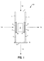
- Fig. 1 provides a diagrammatic view of an enrichment channel for use in a device according to the subject invention.
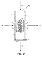
- Fig. 2 provides a diagrammatic view of an alternative embodiment of an enrichment channel also suitable for use in the subject device.
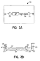
- Fig. 3A provides a top diagrammatic view of a device according to the subject invention.
- Fig. 3B provides a side view of the device of Fig. 3A.
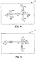
- Fig. 4 provides a diagrammatic top view of another embodiment of the subject invention.
- Fig. 5 provides a diagrammatic view of an embodiment of the subject invention in which the enrichment channel comprises a single fluid inlet and outlet.
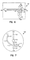
- Fig. 6 provides a diagrammatic view of a device according to the subject invention in which the enrichment channel comprises an electrophoretic gel medium instead of the chromatographic material, as shown in Figs. 1 and 2.
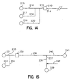
- Fig. 7 provides a diagrammatic top view of disk shaped device according to the subject invention.
- Fig. 8 is a flow diagram of a device as in Figs. 1 or 2.
- Fig. 9 is a flow diagram of a device as in Figs. 3A, 3B.
- Fig. 10 is a flow diagram of a device as in Fig. 4.
- Fig. 11 is a flow diagram of a device as in Fig. 5.
- Fig. 12 is a flow diagram of a device as in Fig. 6.
- Fig. 13 is a flow diagram of a device as in Fig. 7.
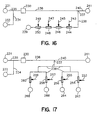
- Fig. 14 is a flow diagram of part of an embodiment of a device according to the invention, showing multiple inlets to the separation channel.
- Fig. 15 is a flow diagram of an embodiment of a device according to the invention, showing an alternative configuration for the intersection between the main and secondary electrophoretic flowpaths.
- Fig. 16 is a flow diagram of an embodiment of a device according to the invention, showing a plurality of analytical zones arranged in series downstream from the enrichment channel.
- Fig. 17 is a flow diagram of an embodiment of a device according to the invention, showing a plurality of analytical zones arranged in parallel downstream from the enrichment channel.
- Fig. 18 is a flow diagram of an embodiment of a device according to the invention, showing a plurality of main electrophoretic flowpaths downstream from the enrichment channel.
- Fig. 19 is a flow diagram of an embodiment of a device according to the invention, showing a plurality of enrichment channels arranged in parallel.
- Figs. 20 and 21 are flow diagrams of embodiments of a device according to the invention, similar to those shown in Figs. 15 and 16, respectively, and additionally having a reagent flowpath for carrying a reagent from a reservoir directly to the main electrophoretic flowpath.
- Fig. 22 is a flow diagram of an embodiment of a device according to the invention, similar to that shown in Fig. 17, respectively, and additionally having a plurality of reagent flowpaths for carrying a reagent from a reservoir directly to downstream branches of the main electrophoretic flowpath.
- Fig. 23 is a flow diagram of an embodiment of a device according to the invention, in which the enrichment medium includes coated magnetic beads.
- Integrated electrophoretic microdevices comprising at least an enrichment channel and a main electrophoretic flowpath are provided. The enrichment channel serves to enrich a particular analyte comprising fraction of a liquid sample. The enrichment channel and main electrophoretic flowpath are positioned in the device so that waste fluid from the enrichment channel does not flow through the main electrophoretic channel, but instead flows away from the main electrophoretic flowpath through a discharge outlet. The subject devices may be used in a variety of electrophoretic applications, including clinical assay applications. In further describing the invention, the devices will first be described in general terms followed by a discussion of representative specific embodiments of the subject devices with reference to the figures.
- The subject device is an integrated electrophoretic microdevice. By integrated is meant that all of the components of the device, e.g., the enrichment channel, the main electrophoretic flowpath, etc., are present in a single, compact, readily handled unit, such as a chip, disk or the like. As the devices are electrophoretic, they are useful in a wide variety of the applications in which entities, such as molecules, particles, cells and the like are moved through a medium under the influence of an applied electric field. Depending on the nature of the entities, e.g., whether or not they carry an electrical charge, as well as the surface chemistry of the electrophoretic chamber in which the electrophoresis is carried out, the entities may be moved through the medium under the direct influence of the applied electric field or as a result of bulk fluid flow through the pathway resulting from the application of the electric field, e.g., electroosmotic flow (EOF). The microdevices will comprise a microchannel as the main electrophoretic flowpath. By microchannel is meant that the electrophoretic chamber of the main electrophoretic flowpath in which the medium is present is a conduit, e.g., trench or channel, having a cross sectional area which provides for capillary flow through the chamber, where the chamber is present on a planar substrate, as will be described below in greater detail.
- Critical to the subject device is an enrichment channel that comprises a sample inlet, a waste fluid outlet, an internal enrichment medium for enriching a particular fraction of a sample, and, optionally, an enriched fraction fluid outlet. The purpose of the enrichment channel is to process the initial sample to enrich for a particular fraction thereof, where the particular fraction being enriched comprises the analyte or analytes of interest. The enrichment channel thus serves to selectively retain and separate the target analyte comprising fraction from the remaining components or the waste portion of the initial sample volume. Depending on the particular application in which the device is employed, the enrichment channel can provide for a number of different functions. The enrichment channel can serve to place the analyte of interest into a smaller volume than the initial sample volume, i.e., it can serve as an analyte concentrator. Furthermore, it can serve to prevent potentially interfering sample components from entering and flowing through the main electrophoretic flowpath, i.e., it can serve as a sample "clean-up" means. In addition, the enrichment channel may serve as a microreactor for preparative processes on target analyte present in a fluid sample, such as chemical, immunological, and enzymatic processes, e.g., labeling, protein digestion, DNA digestion or fragmentation, DNA synthesis, and the like
- The enrichment channel may be present in the device in a variety of configurations, depending on the particular enrichment medium housed therein. The internal volume of the channel will usually range from about 1 pl to 1 µl, usually from about 1 pl to 100 nl, where the length of the channel will generally range from about 1 µm to 5 mm, usually 10 µm to 1 mm, and the cross-sectional dimensions (e.g., width, height) will range from about 1 µm to 200 µm, usually from about 10 µm to 100 µm. The cross-sectional shape of the channel may be circular, ellipsoid, rectangular, trapezoidal, square, or other convenient configuration.
- A variety of different enrichment media may be present in the enrichment channel. Representative enrichment medium or means include those means described in the analyte preconcentration devices disclosed in U.S. 5,202,010; U.S. 5,246,577 and U.S. 5,340,452, as well as Tomlinson et al..
- Specific enrichment means known in the art which may be adaptable for use in the subject integrated microchannel electrophoretic devices include: those employed in protein preconcentration devices described in Kasicka & Prusik, "Isotachophoretic Electrodesorption of Proteins from an Affinity Adsorbent on a Microscale," J. Chromatogr. (1983) 273:117128; capillary bundles comprising an affinity adsorbent as described in U.S. 5,202,101 and WO 93/05390; octadodecylsilane coated solid phases as described in Cai & El Rassi, "On-Line Preconcentration of Triazine Herbicides with Tandem Octadecyl Capillaries-Capillary Zone Electrophoresis," J. Liq. Chromatogr. (1992) 15:1179-1192; solid phases coated with a metal chelating layer as described in Cai & El Rassi, "Selective On-Line Preconcentration of Proteins by Tandem Metal Chelate Capillaries-Capillary Zone Electrophoresis," J. Liq. Chromatogr. (1993) 16:2007-2024; reversed-phase HPLC solid packing materials as described in U.S. 5,246,577), Protein G coated solid phases as described in Cole & Kennedy, "Selective Preconcentration for Capillary Zone Electrophoresis Using Protein G Immunoaffinity Capillary Chromatography," Electrophoresis (1995) 16:549-556; meltable agarose gels as described in U.S. 5,423,966; affinity adsorbent materials as described in Guzman, "Biomedical Applications of On-Line Preconcentration - Capillary Electrophoresis Using an Analyte Concentrator: Investigation of Design Options," J. Liq. Chromatogr. (1995) 18:3751-3568); and solid phase reactor materials as described in U.S. 5,318,680.
- One class of enrichment media or materials that may find use as enrichment media are chromatographic media or materials, particularly sorptive phase materials. Such materials include: reverse phase materials, e.g., C8 or C18 compound coated particles; ion-exchange materials; affinity chromatographic materials in which a binding member is covalently bound to an insoluble matrix, where the binding member may group specific, e.g., a lectin, enzyme cofactor, Protein A and the like, or substance specific, e.g., antibody or binding fragment thereof, antigen for a particular antibody of interest, oligonucleotide and the like, where the insoluble matrix to which the binding member is bound may be particles, such as porous glass, polymeric beads, magnetic beads, networks of glass strands or filaments, a plurality of narrow rods or capillaries, the wall of the channel and the like. Depending on the nature of the chromatographic material employed as the enrichment means, it may be necessary to employ a retention means to keep the chromatographic material in the enrichment channel. Conveniently, glass frits or plugs of agarose gel may be employed to cover the fluid outlets or inlets of the chamber, where the frits or plugs allow for fluid flow but not for particle or other insoluble matrix flow out of the enrichment channel. In embodiments where the enrichment means is a chromatographic material, typically sample will be introduced into, and allowed to flow through, the enrichment channel. As the sample flows through the enrichment channel, the analyte comprising fraction will be retained in the enrichment channel by the chromatographic material and the remaining waste portion of the sample will flow out of the channel through the waste outlet.
- In embodiments where the enrichment means is a bed of polymeric beads or paramagnetic beads or particles, the beads may be coated with antibodies or other target-specific affinity binding moiety, including: affinity purified monoclonal antibodies to any of a variety of mammalian cell markers, particularly human cell markers, including markers for T cells, T cell subsets, B cells, monocytes, stem cells, myeloid cells, leukocytes, and HLA Class II positive cells; secondary antibodies to any of a variety of rodent cell markers, particularly mouse, rat or rabbit immunoglobulins, for isolation ofB cells, T cells, and T cell subsets; uncoated or tosylactivated form for custom coating with any given biomolecule; and streptavidin-coated for use with biotinylated antibodies. Paramagnetic beads or particles may be retained in the enrichment channel by application of a magnetic field.
- Alternatively, or in addition to solid phase materials such as coated particles or other insoluble matrices as the enrichment means, one may employ a coated and/or impregnated membrane which provides for selective retention of the analyte comprising fraction of the sample while allowing the remainder of the sample to flow through the membrane and out of the enrichment means through the waste outlet. A variety of hydrophilic, hydrophobic and ion-exchange membranes have been developed for use in solid phase extraction which may find use in the subject invention. See, for example, Tomlinson et al., "Novel Modifications and Clinical Applications of Preconcentration-Capillary Electrophoresis-Mass Spectrometry," J. Cap. Elect. (1995) 2: 97-104; and Tomlinson et al., "Improved On-line Membrane Preconcentration-Capillary Electrophoresis (mPC-CE),"J. High Res. Chromatogr. (1995) 18:381-3.
- Alternatively or additionally, the enrichment channel or the enrichment medium can include a porous membrane or filter. Suitable materials for capturing genomic DNAs and viral nucleic acids include those marketed by QIAGEN under the name QIAmp, for analysis of blood, tissues, and viral RNAs; and suitable materials for capturing DNAs from plant cells and tissues include those marketed by QIAGEN under the name DNeasy.
- Depending on the configuration of the device, the sample can be caused to flow through the enrichment channel by any of a number of different means, and combinations of means. In some device configurations, it may be sufficient to allow the sample to flow through the device as a result of gravity forces on the sample; in some configurations, the device may be spun about a selected axis to impose a centrifugal force in a desired direction. In other embodiments, active pumping means may be employed to move sample through the enrichment channel and enrichment means housed therein. In other embodiments, magnetic forces may be applied to move the sample or to capture or immobilize a paramagnetic bead-target complex during wash and elution steps. In yet other embodiments of the subject invention, electrodes may be employed to apply an electric field which causes fluid to move through the enrichment channel. An elution liquid will then be caused to flow through the enrichment medium to release the enriched sample fraction from the material and carry it to the main electrophoretic flowpath. Generally, an applied electric field will be employed to move the elution liquid through the enrichment channel.
- Electrophoretic gel media may also be employed as enrichment means in the subject applications. Gel media providing for a diversity of different sieving capabilities are known. By varying the pore size of the media, employing two or more gel media of different porosity, and/or providing for a pore size gradient and selecting the appropriate relationship between the enrichment channel and the main electrophoretic flowpath, one can ensure that only the analyte comprising fraction of interest of the initial sample enters the main electrophoretic flowpath. For example, one could have a device comprising an enrichment channel that intersects the main electrophoretic channel, where the enrichment channel comprises, in the direction of sample flow, a stacking gel of large porosity and a second gel of fine porosity, where the boundary between the gels occurs in the intersection of the enrichment channel and the main electrophoretic flowpath. In this embodiment, after sample is introduced into the stacking gel and an electric field applied to the gels in the enrichment channel, the sample components move through the stacking gel and condense into a narrow band at the gel interface in the intersection of the enrichment channel and main electrophoretic flowpath. A second electric field can then be applied to the main electrophoretic flowpath so that the narrow band of the enriched sample fraction moves into and through the main electrophoretic flowpath. Alternatively, the enrichment channel could comprise a gel of gradient porosity. In this embodiment, when the band(s) of interest reaches the intersection of the enrichment channel and electrophoretic flowpath, the band(s) of interest can then be moved into and along the main electrophoretic flowpath.
- Enrichment media that can be particularly useful for enrichment and/or purification of nucleic acids include sequence specific capture media as well as generic capture media. Generic capture media include, for example: ion exchange and silica resins or membranes which nonspecifically bind nucleic acids, and which can be expected to retain substantially all the DNA in a sample; immobilized single-stranded DNA binding protein (SSB Protein), which can be expected to bind substantially all single-stranded DNA in a sample; poly-dT modified beads, which can be expected to bind substantially all the mRNA in a sample. Sequence specific capture media include beads, membranes or surfaces on which are immobilized any of a variety of capture molecules such as, for example: oligonucleotide probes, which can be expected to bind nucleic acids having complementary sequences in the sample; streptaviden, which can be expected to bind solution phase biotinylated probes which have hybridized with complementary sequences in the sample. Suitable beads for immobilization of capture molecules include chemically or physically crosslinked gels and porous or non-porous resins such as polymeric or silica-based resins.
- Suitable capture media for proteins include the following. Suitable capture media for proteins include: ion exchange resins, including anion (e.g., DEAE) and cation exchange; hydrophobic interaction compounds (e.g., C4, C8 and C18 compounds); sulfhydryls; heparins; inherently active surfaces (e.g., plastics, nitrocellulose blotting papers); activated plastic surfaces; aromatic dyes such as Cibacron blue, Remazol orange, and Procion red. For carbohydrate moieties of proteins, lectins, immobilized hydrophobic octyl and phenylalkane derivatives can be suitable. For enzymes, analogs of a specific enzyme substrate-product transition-state intermediate can be suitable; for kinases, calmodulin can be suitable. Suitable capture media for receptors include receptor ligand affinity compounds.
- As mentioned above, the enrichment channel will comprise at least one inlet and at least one outlet. Of course, where there is a single inlet, the inlet must serve to admit sample to the enrichment channel at an enrichment phase of the process, and to admit an elution medium during an elution phase of the process. And where there is a single outlet, the outlet must serve to discharge the portion of the sample that has been depleted of the fraction retained by the enrichment media, and to pass to the main electrophoretic microchannel the enriched fraction during the elution phase. Depending on the particular enrichment means housed in the enrichment channel, as well as the particular device configuration, the enrichment channel may have more than one fluid inlet, serving as, e.g., sample inlet and elution buffer inlet; or the enrichment channel may have more than one outlet, serving as, e.g., waste outlet and enriched fraction fluid outlet. Where the enrichment channel is in direct fluid communication with the main electrophoretic channel, i.e., the enrichment channel and main electrophoretic flowpath are joined so that fluid flows from the enrichment channel immediately into the main electrophoretic flowpath, the enrichment channel will comprise, in addition to the waste outlet, an enriched fraction fluid outlet through which the enriched fraction of the sample flows into the main electrophoretic flowpath. When convenient, e.g., for the introduction of wash and/or elution solvent into the enrichment channel, one or more additional fluid inlets may be provided to conduct such solvents into the enrichment channel from fluid reservoirs. To control bulk fluid flow through the enrichment channel, e.g., to prevent waste sample from flowing into the main electrophoretic flowpath, fluid control means, e.g., valves, membranes, etc., may be associated with each of the inlets and outlets. Where desirable for moving fluid and entities through the enrichment channel, e.g., sample, elution buffer, reagents, reactants, wash or rinse solutions, etc., electrodes may be provided capable of applying an electric field to the material and fluid present in the enrichment channel.
- The next component of the subject devices is the main electrophoretic flowpath. The main electrophoretic flowpath may have a variety of configurations, including tube-like, trench-like or other convenient configuration, where the cross-sectional shape of the flowpath may be circular, ellipsoid, square, rectangular, triangular and the like so that it forms a microchannel on the surface of the planar substrate in which it is present. The microchannel will have cross-sectional area which provides for capillary fluid flow through the microchannel, where at least one of the cross-sectional dimensions, e.g., width, height, diameter, will be at least about 1 µm, usually at least about 10 µm, but will not exceed about 200 µm, and will usually not exceed about 100 µm. Depending on the particular nature of the integrated device, the main electrophoretic flowpath may be straight, curved or another convenient configuration on the surface of the planar substrate.
- The main electrophoretic flowpath, as well as any additional electrophoretic flowpaths, will have associated with it at least one pair of electrodes for applying an electric field to the medium present in the flowpath. Where a single pair of electrodes is employed, typically one member of the pair will be present at each end of the pathway. Where convenient, a plurality of electrodes may be associated with the electrophoretic flowpath, as described in U.S. 5,126,022,
where the plurality of electrodes can provide for precise movement of entities along the electrophoretic flowpath. The electrodes employed in the subject device may be any convenient type capable of applying an appropriate electric field to the medium present in the electrophoretic flowpath with which they are associated. - Critical to the subject invention is that the enrichment channel and the main electrophoretic flowpath are positioned in the device so that substantially only the enriched fraction of the sample flows through the main electrophoretic flowpath. To this end, the device will further comprise a discharge outlet for discharging a portion of sample other than the enriched fraction, e.g., the waste portion, away from the main electrophoretic flowpath. Thus, where the enrichment channel is in direct fluid communication with the main electrophoretic flowpath, the waste fluid flowpath through the enrichment channel will be in an intersecting relationship with the main electrophoretic flowpath. In other embodiments of the subject invention where the enrichment channel and main electrophoretic flowpath are connected by a second electrophoretic flowpath so that they are in indirect fluid communication, the waste flowpath through the enrichment channel does not necessarily have to be in an intersecting relationship with the main electrophoretic flowpath; the waste flowpath and main electrophoretic flowpath could be parallel to one another.
- The subject devices will also comprise a means for transferring the enriched fraction from the enrichment channel to the main electrophoretic flowpath. Depending on the particular device configuration, the enriched fraction transfer means can be an enriched fraction fluid outlet, a secondary electrophoretic pathway, or other suitable transfer means. By having a second electrophoretic flowpath in addition to the main electrophoretic flowpath, the possibility exists to employ the second electrophoretic flowpath as a conduit for the enriched sample fraction from the enrichment channel to the main electrophoretic flowpath. In those embodiments where the waste outlet is the sole fluid outlet, the presence of a secondary electrophoretic flowpath will be essential, such that the enrichment channel and the main electrophoretic flowpath are in indirect fluid communication.
- In addition to the main and any secondary electrophoretic flowpath serving as an enriched sample transfer means, the subject devices may further comprise one or more additional electrophoretic flowpaths, which may or may not be of capillary dimension and may serve a variety of purposes. With devices comprising a plurality of electrophoretic flowpaths, a variety of configurations are possible, such as a branched configuration in which a plurality of electrophoretic flowpaths are in fluid communication with the main electrophoretic flowpath. See U.S. 5,126,022.
- The main electrophoretic flowpath and/or any secondary electrophoretic flowpaths present in the device may optionally comprise, and usually will comprise, fluid reservoirs at one or both termini, i.e., either end, of the flowpaths. Where reservoirs are provided, they may serve a variety of purposes, such as a means for introducing buffer, elution solvent, reagent, rinse and wash solutions, and the like into the main electrophoretic flowpath, receiving waste fluid from the electrophoretic flowpath, and the like.
- Another optional component that may be present in the subject devices is a waste fluid reservoir for receiving and storing the waste portion of the initial sample volume from the enrichment channel, where the waste reservoir will be in fluid communication with the discharge outlet. Depending on the particular device configuration, the discharge outlet may be the same as, or distinct from, the waste outlet, and may open into a waste reservoir or provide an outlet from the device. The waste reservoir may be present in the device as a channel, compartment, or other convenient configuration which does not interfere with the other components of the device.
- The subject device may also optionally comprise an interface means for assisting in the introduction of sample into the sample preparation means. For example, where the sample is to be introduced by syringe into the device, the device may comprise a syringe interface which serves as a guide for the syringe needle into the device, as a seal, and the like.
- Depending on the particular configuration and the nature of the materials from which the device is fabricated, at least in association with the main electrophoretic flowpath will be a detection region for detecting the presence of a particular species in the medium contained in the electrophoretic flowpath. At least one region of the main electrophoretic flowpath in the detection region will be fabricated from a material that is optically transparent, generally allowing light of wavelengths ranging from 180 to 1500 nm, usually 220 to 800 nm, more usually 250 to 800 nm, to have low transmission losses. Suitable materials include fused silica, plastics, quartz glass, and the like.
- The integrated device may have any convenient configuration capable of comprising the enrichment channel and main electrophoretic flowpath, as well as any additional components. Because the devices are microchannel electrophoretic devices, the electrophoretic flowpaths will be present on the surface of a planar substrate, where the substrate will usually, though not necessarily, be covered with a planar cover plate to seal the microchannels present on the surface from the environment. Generally, the devices will be small, having a longest dimension in the surface plane of no more than about 200 mm, usually no more than about 100 mm so that the devices are readily handled and manipulated. As discussed above, the devices may have a variety of configurations, including parallelepiped, e.g., credit card or chip like, disk like, syringe like or any other compact, convenient configuration.
- The subject devices may be fabricated from a wide variety of materials, including glass, fused silica, acrylics, thermoplastics, and the like. The various components of the integrated device may be fabricated from the same or different materials, depending on the particular use of the device, the economic concerns, solvent compatibility, optical clarity, color, mechanical strength, and the like. For example, both the planar substrate comprising the microchannel electrophoretic flowpaths and the cover plate may be fabricated from the same material, e.g., polymethylmethacrylate (PMMA), or different materials, e.g., a substrate of PMMA and a cover plate of glass. For applications where it is desired to have a disposable integrated device, due to ease of manufacture and cost of materials, the device will typically be fabricated from a plastic. For ease of detection and fabrication, the entire device may be fabricated from a plastic material that is optically transparent, as that term is defined above. Also of interest in certain applications are plastics having low surface charge under conditions of electrophoresis. Particular plastics finding use include polymethylmethacrylate, polycarbonate, polyethylene terepthalate, polystyrene or styrene copolymers, and the like.
- The devices may be fabricated using any convenient means, including conventional molding and casting techniques. For example, with devices prepared from a plastic material, a silica mold master which is a negative for the channel structure in the planar substrate of the device can be prepared by etching or laser micromachining. In addition to having a raised ridge which will form the channel in the substrate, the silica mold may have a raised area which will provide for a cavity into the planar substrate for housing of the enrichment channel. Next, a polymer precursor formulation can be thermally cured or photopolymerized between the silica master and support planar plate, such as a glass plate. Where convenient, the procedures described in U.S. 5,110,514 may be employed. After the planar substrate has been fabricated, the enrichment channel may be placed into the cavity in the planar substrate and electrodes introduced where desired. Finally, a cover plate may be placed over, and sealed to, the surface of the substrate, thereby forming an integrated device. The cover plate may be sealed to the substrate using any convenient means, including ultrasonic welding, adhesives, etc.
- Generally, prior to using the subject device, a suitable first or electrophoretic medium will be introduced into the electrophoretic flowpaths or microchannels of the device, where the first medium will be different from the enrichment medium present in the enrichment channel. Electrophoretic media is used herein to refer to any medium to which an electric field is applied to move species through the medium. The electrophoretic media can be conveniently introduced through the reservoirs present at the termini of the electrophoretic flowpaths or directly into the channels or chambers of the electrophoretic flowpaths prior to sealing of the cover plate to the substrate. Any convenient electrophoretic medium may be employed. Electrophoretic media suitable for use, depending on the particular application, include buffers, crosslinked and uncrosslinked polymeric media, organic solvents, detergents, and the like, as disclosed in Barron & Blanch, "DNA Separations by Slab Gel and Capillary Electrophoresis: Theory and Practice," Separation and Purification Methods (1995) 24:1-118, as well as in U.S. Patent Applications Serial Nos. 08/241,048, 08/636,599 and 08/589,150.
- Of particular interest as electrophoretic media are cellulose derivatives, polyacrylamides, polyvinyl alcohols, polyethylene oxides, and the like.
- The subject invention will now be further described in terms of the figures. Fig. 1 provides a diagrammatic view of an enrichment channel which may find use in the devices of the subject invention.
Enrichment channel 10 comprisesside walls 1 which enclose reversephase C18 material 2.Channel 10 further comprisefluid inlets 7 and 4 andfluid outlets valves inlet 4 andoutlet 5 but restrainreverse phase material 2 in the channel. In using this enrichment channel, sample is introduced through sample inlet 7 in the direction offlowpath 12. As sample moves throughchannel 10, the analyte comprising fraction is retained onreverse phase material 2 while the remaining waste fraction of the sample flows outwaste outlet 6 alongflowpath 13.Valves inlet 4 oroutlet 5. After the sample has flowed throughchannel 10,valve 11 is shut andvalves channel 10 throughglass frit 3 andinlet 4 in the direction offlowpath 14. As elution buffer moves throughmaterial 2, the retained fraction of the sample is released and carried with the elution buffer out enrichedfraction outlet 5 throughfrit 3 alongflowpath 15. - In Fig. 2, the same enrichment channel as shown in Fig. 1 is depicted with the exception that reverse
phase material 2 is replaced by a network ofcrosslinked glass filaments 16 to which binding pair member is covalently bound. - Fig. 3A provides a diagrammatic top view of a credit card shaped (parallelepiped) device according to the subject invention.
Device 30 comprisesmain electrophoretic flowpath 31 havingreservoir 32 at a first end andreservoir 33 at a second end. In direct fluid communication withmain electrophoretic flowpath 31 is enrichment channel 34 (seen from overhead).Electrodes electrophoretic flowpath 31.Detection region 37 is positioned overelectrophoretic flowpath 31 for viewing analyte present in the medium comprised in the flowpath. A detection region can also be provided over theenrichment channel 34. Although the device shown in Fig. 3A comprises a single enrichment channel, additional enrichment channels could be provided in the flowpath, including in the detection region. - Fig. 3B provides a diagrammatic side view of the device depicted in Fig. 3A. In using this embodiment of the subject invention, sample is introduced through
syringe interface 38 intoenrichment channel 34, where the analyte comprising fraction of the sample is retained as the waste fraction flows out of theenrichment channel 34 throughdischarge outlet 39 and out of the device. Elution buffer is then introduced intoreservoir 32 throughport 40. An electric field is then applied betweenelectrodes reservoir 32 throughenrichment channel 34 and alongelectrophoretic flowpath 31 toreservoir 33. As the elution buffer moves throughenrichment channel 34, it releases the retained analyte comprising fraction of the initial sample volume and carries it intoelectrophoretic flowpath 31. - Fig. 4 shows a diagrammatic view of an embodiment of the subject invention in which the
enrichment channel 62 is separated frommain electrophoretic flowpath 52 bysecondary electrophoretic flowpath 55. Withdevice 50, sample is introduced intoenrichment channel 62 throughsyringe interface 66. As sample flows throughenrichment channel 62, waste sample flows throughdischarge outlet 64 intowaste reservoir 63. An electric field is then applied betweenelectrodes reservoir 57 to move throughenrichment channel 62, resulting in the release of analyte. Analyte is then carried alongsecondary electrophoretic flowpath 55 along with the elution buffer. When analyte reachesintersection 51, the electric field betweenelectrodes electrodes intersection 51 may be determined by detecting the presence of analyte in the intersection or by empirically determining the time at which the analyte should reach the intersection, based on the particular nature of the analyte, the medium in the flowpath, the strength of the electric field, and the like. Following application of the electric field betweenelectrodes reservoirs intersection 51 alongelectrophoretic flowpath 52 towardsreservoir 53 and throughdetection region 65. - Fig. 5 provides a diagrammatic top view of yet another embodiment of the subject invention in which the enrichment channel comprises a single fluid inlet and outlet.
Device 70 comprisesmain electrophoretic flowpath 71 in intersecting relationship withsecondary electrophoretic flowpath 73. Upstream from theintersection 82 alongsecondary electrophoretic flowpath 73 isenrichment channel 72. In using this embodiment, sample is introduced throughsyringe interface 80 intoenrichment channel 72, whereby the analyte comprising fraction of the sample is reversibly bound to the material present in the enrichment channel. An electric field is then applied betweenelectrodes enrichment channel 72, alongsecondary electrophoretic flowpath 73,past intersection 82, and outdischarge outlet 84 intowaste reservoir 78. An elution buffer is then introduced intoenrichment channel 72 throughsyringe interface 80 and an electric field applied betweenelectrodes enrichment channel 72 into secondary flowelectrophoretic flowpath 73, carrying analyte along with it. When analyte reachesintersection 82, the electric field betweenelectrodes electrodes 76 and 77, which causes analyte to move alongmain electrophoretic flowpath 71 and towardsreservoir 74 throughdetection region 99. - The device shown diagrammatically in Fig. 6 comprises an enrichment channel having an electrophoretic enrichment means, instead of the chromatographic enrichment means of the devices of Figs. 1 to 5. In
device 90, sample is introduced intoreservoir 96 and an electric field is applied betweenelectrodes reservoir 98. As the sample migrates towardsreservoir 98 it enters stackinggel 93 having a relatively large pore size and travels towardssecondary gel 92 of relatively fine pore size. Atinterface 94, the sample components are compressed into a narrow band. At this point, the electric field betweenelectrodes electrodes interface 94 to migrate intomain electrophoretic flowpath 95,past detection region 91 and towardsreservoir 85. Indevice 90, instead of the stacking gel configuration, one could provide for a molecular size membrane at the region ofinterface 94, which can provide for selective passage of sample components below a threshold mass and retention at the membrane surface of components in excess of the threshold mass. In yet another modification of the device shown in Fig. 6, present at the location ofinterface 94 could be an electrode by which an appropriate electric potential could be applied to maintain a sample component of interest in the region of 93, thereby providing for component concentration in the region of 93. For example, for an anionic analyte of interest, upon introduction of sample intoreservoir 96 and application of an electric field between 93 and 87, in which 93 is the positive electrode and 87 the ground, the ionic analyte will migrate towards and concentrate in the region of 93. After the analyte has concentrated in the region ofelectrode 93, an electric field can then be applied between 89 and 90 causing the anionic analyte to migrate towardsreservoir 85. - Fig. 7 provides a top diagrammatic view of a disk shaped embodiment of the subject device, as opposed to the credit card shaped embodiments of Figs. 3 to 6. In
device 100, sample is first introduced intoenrichment channel 102. An electric field is then applied betweenelectrodes elution buffer 103 throughenrichment channel 102, whereby analyte retained in theenrichment channel 102 is released and carried with the elution buffer tointersection 114. The electric field between 108 and 109 is then replaced with an electric field between 110 and 111, causing analyte to move fromintersection 114 alongmain electrophoretic flowpath 112,past detection region 113 and towardsreservoir 107. - Other embodiments may be understood by reference to the flow diagrams in Figs. 8 through 19, some of which correspond to embodiments shown in the sketches of Figs. 1 through 7. Referring, for example, to Fig. 8, there is shown a flow diagram of an enrichment channel as shown in Fig. 1 or Fig. 2, with corresponding identification numbers. Accordingly, as described with reference to Figs. 1 and 2, sample enters
enrichment channel 10 through sample inlet 7 by way offlowpath 12. As the sample moves throughenrichment channel 10 the fraction containing the fraction of interest is retained on an enrichment medium, which may be, for example, a reverse phase C18 material (as described with reference to Fig. 1) or binding pair members covalently bound to a network of glass filaments (as described with reference to Fig. 2), while the remaining waste fraction flows out throughwaste outlet 6 alongflowpath 13. After a suitable quantity of sample has flowed throughenrichment channel 10, flow through inlet 7 andoutlet 6 is halted, and elution buffer entersenrichment channel 10 throughinlet 4 by way offlowpath 14. Withinenrichment channel 10 the retained fraction of interest is released into the elution buffer passing over the enrichment medium, and passes out through enrichedfraction outlet 5 by way offlowpath 15. - And referring to Fig. 9, there is shown a flow diagram of the embodiment of a
device 30 as sketched in two views in Figs. 3A, 3B and described with reference thereto. In the flow diagrams, the enrichment channel (34 in Figs. 3A, 3B, 9) is represented by a square; the various reservoirs (e.g., 32, 33 in Figs. 3A, 3B, 9) are represented by small circles at the ends of the flowpaths (channels), which are represented by lines (e.g.,main electrophoretic flowpath 31 in Figs. 3A, 3B, 9); electrodes (35, 36 in Figs. 3A, 3B, 9) are represented by hairlines running to the centers of the reservoir circles; an interface for syringe injection (where one may be present; e.g., 38 in Figs. 3B, 9) is represented by a trapezoid at the end of the sample input flowpath; and the detection region (37 in Figs. 3A, 3B, 9) is represented by a heavy arrow touching the main electrophoretic channel. Similarly, in Fig. 12, there is shown a flow diagram of the embodiment of adevice 90 as sketched in Fig. 6 and described above with reference thereto. In this embodiment, the enrichment channel (120 in Fig. 12) works by electrophoretic enrichment, which results in accumulation of the fraction of interest at the point where the enrichment channel 120 is intersected by the mainelectrophoretic channel 95. Movement of sample material through the enrichment channel can be accomplished by application of an electrical potential difference betweenelectrodes detection region 91 can be accomplished by application of an electrical potential difference betweenelectrodes interface 94 between a stackinggel 93 and asecondary gel 92; and in a further modification, a suitable electrical potential can be applied at an electrode (121 in Fig. 12) at the site of theinterface 93 to provide for component concentration in that region of the enrichment channel. - Fig. 10 is a flow diagram of the embodiment of a
device 50 in which theenrichment channel 62 is separated frommain electrophoretic flowpath 52 bysecondary electrophoretic flowpath 55, as sketched in Fig. 4 and described above with reference thereto. Similarly, Fig. 13 is a flow diagram of the disc-shaped embodiment of adevice 100 as sketched in Fig. 7 and described with reference thereto. Fig. 13 shows the sample input flowpath by which the sample is introduced from thesyringe interface 66 into theenrichment channel 102, and thedischarge outlet 64 by which waste passes out to wastereservoir 63 while the fraction of interest is retained on the retention medium in the enrichment channel. These features are not shown in the top views of Fig. 7 or Fig. 4. - In Fig. 11 there is shown a flow diagram of a
device 70, in which there is only one fluid inlet into, and one fluid outlet out from, theenrichment channel 72, as sketched in Fig. 5 and described with reference thereto. During sample injection by way of the syringe interface thefluid inlet 116 serves as a sample inlet and thefluid outlet 118 serves as a waste outlet. While the fraction of interest is retained by the retention medium in the enrichment channel, the waste fraction flows downstream through thesecondary electrophoretic flowpath 73, across theintersection 82 of the secondary electrophoretic flowpath with themain electrophoretic flowpath 71, and intodischarge outlet 84, which directs the waste away from themail electrophoretic flowpath 71 towardwaste reservoir 78. During elution, elution buffer is injected by way of the syringe interface;fluid inlet 116 serves as an elution buffer inlet and thefluid outlet 118 serves as an enriched fraction outlet to the secondary electrophoretic channel. The fraction of interest moves into the elution buffer in which it is driven electrokinetically in an electric field produced by applying a voltage acrosselectrodes electrodes 76, 77 to draw the analyte or analytes in the fraction of interest into and along the main electrophoretic flowpath to thedetection zone 99. - As noted with reference to Fig. 5, the waste fraction (material not bound to the enrichment medium) can be washed out of the enrichment channel and away from the main electrophoretic pathway by application of an electric field between electrodes upstream from the enrichment channel and downstream from the discharge outlet. That is, prior to introducing the elution buffer to the enrichment channel, a liquid wash medium is passed over the enrichment medium and out through the discharge outlet, carrying away waste fraction components. Any of a variety of materials can be suitable as a wash medium, so long as the wash medium does not substantially elute the fraction of interest from the enrichment medium. Moreover, the wash medium can be chosen to facilitate a selective release or removal, prior to elution, of undesired components that may be bound to or otherwise associated with the enrichment medium. For example, where the components of interest are DNA fragments, the wash medium may contain enzymes that selectively degrade proteins or polypeptides or that selectively degrade RNAs, facilitating the removal of these contaminants away from the fraction of interest prior to elution. Or, for example, where the components of interest are proteins, the wash medium may contain DNAses and RNAses.
- Sequential movement of the various liquids into and through the enrichment channel can be readily controlled by providing a reservoir and a flowpath to the upstream part of the enrichment channel for each such liquid. As illustrated in the flow diagram of Fig. 14, for example, an
input 212 toenrichment channel 210 is fed by asample supply flowpath 220 running from asample reservoir 218, by awash medium flowpath 218 running from awash medium reservoir 217, and by anelution medium flowpath 216 running from anelution medium reservoir 215. Movement of these materials can be selectively controlled by application of electrical potentials across electrodes (not shown the Fig.) at the respective reservoirs and at suitable points (as described herein for various configurations) downstream fromenrichment channel output 214. Suitable wash media for proteins include, for example, pH-adjusted buffers and organic solvents; and washing can be effected by, for example, adjusting ionic strength or temperature of the wash medium. - Other materials may be introduced to the input flowpath as well, and, particularly, one or more reagent streams can be provided for pretreatment of the sample itself prior to moving it onto the enrichment channel. A crude sample of body fluid (blood, lymphatic fluid, amniotic fluid, cerebrospinal fluid, or urine, for example) can be pretreated by combining the sample with a reagent in the sample flowpath. For example, DNA may be released from cells in a crude sample of whole blood by admixture of a reagent containing an enzyme or a detergent.
- Other flowpath configurations downstream from the enrichment channel can be employed, and certain of these may provide some advantages for particular kinds of downstream treatment or analysis of the components of the fraction of interest. In Fig. 15, for example, the secondary electrophoretic flowpath does not cross the main electrophoretic flowpath; rather,
main electrophoretic flowpath 238 joinssecondary electrophoretic flowpath 236 at a T intersection (compare, Fig. 12). In this configuration, the upstream arm of the main electrophoretic flowpath runs in the same channel as thesecondary electrophoretic flowpath 236. As in other configurations, described herein, sample enters theenrichment channel 230 by way ofsample flowpath 234 fromsample reservoir 233; and during the enrichment stage the waste fluid passes out fromenrichment channel 230 by way ofsecondary electrophoretic flowpath 236, then pastT intersection 237 and away throughdischarge outlet 240 towaste reservoir 241. Once the enrichment stage is complete, a wash medium may be passed through the enrichment channel and also out through the discharge outlet. The wash medium may be introduced by way of the sample supply flowpath or, optionally; from a separate wash medium flowpath as described above with reference to Fig. 14. Movement of the sample and the wash medium can be accomplished by application of an electric field across electrodes (not shown in the Fig.) atwaste reservoir 241 and, respectively, sample reservoir 233 (and, optionally, a wash reservoir). Then, an elution medium can be moved from anelution buffer reservoir 231 by way of elution buffer flowpath 235 into and throughenrichment channel 230, throughsecondary electrophoresis flowpath 236. Media downstream from the eluting fraction components can be directed away frommain electrophoretic flowpath 238 and out by way ofwaste discharge flowpath 240, until the most downstream component of interest has reached theintersection 237. Then an electrical potential can be applied atreservoir 239 to draw the components fromsecondary electrophoretic flowpath 236 throughintersection 237 and withinmain electrophoretic flowpath 238 toward and throughdetection region 242. - An intersection of the main and secondary electrophoretic flowpaths at an "injection cross", as shown for example in Figs. 5, 12, can be advantageous where precise metering of the sample plug is desired, as for example, where the main electrophoretic flowpath is used for electrophoretic separation. Such an injection cross can provide for injection from the intersection of a geometrically defined plug of sample components from the fraction of interest.
- On the other hand, where precise control of a sample plug is not desirable, and particularly where it is desirable to move the entire eluted sample through the main electrophoretic path way, a T intersection can be preferred. Such a configuration may be advantageous where, for example, the components are analyzed by passing substantially the entire eluted fraction through an array of affinity zones downstream from the intersection.
- By way of example, Fig. 16 is a diagram showing the flow in a configuration having a serial array of
affinity zones enrichment channel 230 and concentrated and/or purified inenrichment channel 230, so that the eluted fraction that passes intomain electrophoretic flowpath 238 consists principally of a complex mixture of DNA fragments of different lengths and base composition. Each hybridization zone is itself an enrichment channel, in which the enrichment medium includes an immobilized oligonucleotide probe having a sequence complementary to a sequence in a target DNA. As the eluted fraction passes serially through theaffinity zones detectors 243, 245, 247, 249, configured to detect and, optionally, to quantify, a signal (such as fluorescence or electrochemilluminescence) from components of interest bound in the affinity zones. Any form of biomolecular recognition may be employed as a capture principle in the affinity zones, as the skilled artisan will appreciate. Useful types of affinity include antibody-antigen interactions; binding of poly-dT with adenylated RNA; oligonucleotide probes for RNA, DNA, PNA; streptavidin-biotin binding; protein-DNA interactions, such as DNA-binding protein G or protein A; and molecules having group specific affinities, such as arginine, benzamidine, heparin, and lectins. Other examples will be apparent to the skilled artisan. - Accordingly, for example, the capture principle may include receptor-ligand binding, antibody-antigen binding, etc., and thus the methods and devices according to the invention can be useful for carrying out immunoassays, receptor binding assays, and the like, as well as for nucleic acid hybridization assays.
- Alternatively, as mentioned above, the main electrophoretic flowpath can be branched downstream from the intersection with the secondary electrophoretic flowpath, providing a parallel array of main electrophoretic flowpaths, as shown by way of example in Fig. 17. Electrophoretic flowpath 238 is shown as twice bifurcated, so that four main electrophoretic flowpath branches run downstream to their
respective waste reservoirs affinity zones detectors - Where the affinity zones are arranged in parallel, as for example in Fig. 17, each affinity zone receives an aliquot of the entire sample that is delivered to the main electrophoresis channel. In this embodiment, sample components that can be captured by two or more of the affinity media will appear in the respective two or more affinity zones. For example, a nucleic acid fragment that contains either one or both of two sequences complementary to two of the probe sequences will, in the parallel arrangement, be captured in the two affinity zones containing those two probes. On the other hand, where the affinity zones are serially arrayed, as for example in Fig. 16, each downstream affinity zone is reached only by sample components not captured by an affinity zone upstream from it. Here, for example, a nucleic acid fragment that contains both of two sequences complementary to probe sequences in two of the affinity zones will be captured only in the more upstream of the two affinity zones. This arrangement may be advantageous where it is desirable to identify sample components that contain one but not another moiety or sequence.
- And alternatively, as noted above, a plurality of main electrophoretic flowpaths may be provided for treatment of the enriched eluted sample. As shown by way of example in Fig. 18, the
main electrophoretic flowpaths 270 may carry eluted sample fraction from thesecondary electrophoretic flowpath 236 through a series ofintersections 272. Eachmain electrophoretic flowpath 270 is provided with reservoirs upstream (274) and downstream (276) and each is provided with adetector 278. This configuration may be employed to run a set of tests or assays or measurements on aliquots of a single enriched sample fraction, and will be particularly useful where, as noted above, precise metering of the quantity of analyte is desirable. As will be appreciated, each of themain electrophoretic flowpaths 270 can be provided with an affinity zone or with an array of affinity zones (not shown in Fig. 18) as described above with reference to Figs. 16, 17. - Or, as shown by way of example in Fig. 19, a plurality of
enrichment channels 280 can receive sample from a branchedsample supply manifold 281. Eachenrichment channel 280 can during the elution stage deliver an enriched fraction to anintersection 288 with amain electrophoretic flowpath 284. During the enrichment stage (and optionally during a wash stage) waste fraction is carried away from theintersections 288 by way of abranched discharge manifold 283 and out throughdischarge outlet 240 towaste reservoir 241. Such an arrangement can be used to particular advantage, for example, where the fraction of interest is a mixture of DNAs, and where it is desirable to obtain both sequence information and size information for the DNAs. The configuration of Fig. 19 can be used, for example, for a flow-through analysis analogous to a Southern blot analysis. In the conventional Southern blot analysis, DNA fragments are first separated on a gel, and then transferred to a membrane on which probes are allowed to bind complementary fragments. The Southern blot analysis is practiced mainly as a manual bench-top procedure, and is highly labor-intensive, taking several days to complete. The flow-through analysis, according to the invention, can be substantially automated, and the analysis can be completed much more rapidly. - In the flow-through analysis, each but one of the enrichment channels is provided with a sequence-specific capture medium, such as a sequence-specific immobilized oligonucleotide probe, and the last one of the enrichment channels is provided with a generic capture medium which binds all DNA fragments in the sample. These different enriched fractions are delivered to the
intersections 288 during the elution stage, and then they are moved electrophoretically in the respectivemain electrophoretic flowpaths 284, each provided with adetector 286. The enriched fraction from the enrichment channel containing a generic capture medium contains a mixture of all sizes of DNAs from the sample, having a range of electrophoretic mobilities, passing the detector sequentially, and resulting in a series of signal peaks. The enriched fraction from each of the other enrichment channels contains only DNAs complementary to the specific capture medium in its respective enrichment channel. - In some embodiments it may be desirable to combine one or more reagents with the enriched fraction downstream from the intersection of the secondary flowpath and the main electrophoretic flowpath Fig. 20 is a flow diagram similar to one shown in Fig. 15. In Fig. 20 a
reagent flowpath 300 carries a reagent (or reagents) from areservoir 301 to themain electrophoretic flowpath 238, where the reagent can combine with and react with one or more analytes in the enriched fraction. And, as will be appreciated, where the main electrophoretic flowpath is branched downstream from the intersection with the secondary electrophoretic flowpath, producing subfractions in the branches, each such downstream branch can be provided with a reagent flowpath carrying reagent from a reservoir. Such a configuration can provide either for replicate treatment of the subfractions with a single reagent, or for treatment of each subfraction with a different reagent, or for simultaneous treatment of subfractions with two or more reagents, each producing a particular desired result upon interaction with the analyte(s) in the enriched subfraction. - Figs. 21 and 22 are flow diagrams similar to those shown in Figs. 16 and 17, having multiple branched main electrophoretic flowpaths, each branch provided with an affinity zone. In Fig. 21
reagent flowpath 300 carries a reagent (or reagents) from areservoir 301 to themain electrophoretic flowpath 238, where the reagent can combine with and react with one or more analytes in the enriched fraction. In this embodiment, because thereagent flowpath 300 intersects themain electrophoretic flowpath 238 at a point upstream from the first bifurcation, the reagent supplied byreservoir 301 effects a replicate treatment of all the subfractions that are treated on the downstream branches and detected in the respective affinity zones. In Fig. 22, each of the downstream branches of themain electrophoretic flowpath 238 is provided with reagent flowpath (302, 304, 306, 308) each carrying a reagent from a separate reagent reservoir (303, 305, 307, 309). Such a configuration can provide for different treatment of the subfractions, for example, providing independent stringency control of parallel hybridization zones. - For example, devices providing flowpaths as in any of Figs. 18 through 22, or a combination of these, can be used for DNA profiling. More specifically, for example, restriction fragment polymorphism ("RFLP") analysis can be carried out by employing a plurality of different single-locus RFLP probes in
reservoirs - The subject devices may be used in a variety of applications, where one or more electric fields are applied to a medium to move entities through the medium. Representative applications include electrophoretic separation applications, nucleic acid hybridization, ligand binding, preparation applications, sequencing applications, synthesis applications, analyte identification applications, including clinical, environmental, quality control applications, and the like. Thus, depending on the particular application a variety of different fluid samples may be introduced into the subject device, where representative samples include bodily fluids, environmental fluid samples, e.g., water and the like, or other fluid samples in which the identification and/or isolation of a particular analyte is desired. Depending on the particular application, a variety of different analytes may be of interest, including drugs, toxins, naturally occurring compounds such as peptides and nucleic acids, proteins, glycoproteins, organic and inorganic ions, steroids, and the like. Of particular interest is the use of the subject devices in clinical applications, where the samples that may be analyzed include blood, urine, plasma, cerebrospinal fluid, tears, nasal or ear discharge, tissue lysate, saliva, ocular scratches, fine needle biopsies, and the like, where the sample may or may not need to be retreated, i.e., combined with a solvent to decrease viscosity, decrease ionic strength, or increase solubility or buffer to a specific pH, and the like, prior to introduction into the device. For clinical applications, analytes of interest include anions, cations, small organic molecules including metabolites of drugs or xenobiotics, peptides, proteins, glycoproteins, oligosaccharides, oligonucleotides, DNA, RNA, lipids, steroids, cholesterols, and the like.
- The following examples are offered by way of illustration and not by way of limitation.
- High Efficiency Separation of Organic Analytes in an Aqueous Sample.
- A card as shown in Fig. 4 is used in the separation of organic analytes in an aqueous sample as follows in conjunction with a device that provides for the application of appropriate electric fields through introduction of electrodes into each reservoir of the card and provides for a means of detecting analyte as it passes through
detection region 65. InCard 50, theenrichment channel 62 comprises porous beads coated with a C-18 phase, while the reservoirs and channels, except for the waste reservoir, comprise 20 millimolar borate buffer. A 100 µl aqueous sample is injected intoenrichment channel 62 throughinterface 66. Substantially all of the organic analyte in the sample reversibly binds to the C18 coated porous beads, while the remaining sample components flow out ofenrichment channel 62 intowaste reservoir 63. 10 µl of an elution buffer (90% methanol/ 10% 20 millimolar borate buffer pH 8.3) are then introduced into theenrichment channel 62 throughinterface 66, whereby the reversibly bound organic analyte becomes free in the elution buffer. Because of the small volume of elution buffer employed, the concentration of analyte in the volume of elution buffer as compared to the analyte concentration in the original sample is increased 100 to 1000 times. The seals overreservoirs electrodes intersection 51. A voltage gradient is then applied betweenelectrodes separation channel 52, yielding high efficiency separation of the organic analytes. - The above experiment is also performed in a modified version of the device depicted in Fig. 4. In the modified device, in addition to
reservoir 57, the device comprises an elution buffer reservoir also in fluid communication with theenrichment channel 62. In this experiment, sample is introduced intoenrichment channel 62, whereby the organic analytes present in the elution buffer reversibly bind to the C18 phase coated beads present in the enrichment channel. An electric field is applied between an electrode present in the elution buffer reservoir andelectrode 60 for a limited period of time sufficient to cause 10 µl of elution buffer to migrate through the enrichment channel and release any reversibly bound organic analyte. After the elution buffer has moved into the enrichment channel, a voltage gradient is then applied betweenelectrodes intersection 51, as described above. - Sample enrichment employing paramagnetic beads for enrichment within an integrated microfluidic device.
- Experimental protocols based on biomagnetic separation methods are provided as embodiments of the current invention. In a microfluidic device configured generally as illustrated in Fig. 23, and described with reference thereto, a crude sample composed of a particular target is treated using magnetic beads, coated with an affinity medium, to capture a target having a binding affinity for the specific affinity medium. Such magnetic beads are marketed, for example, by Dynal, Inc. New York, under the name Dynabeads®. Dynabeads are superparamagnetic, monodispersed polystyrene microspheres coated with antibodies or other binding moieties that selectively bind to a target, which may be or include cells, genes, bacteria, or other biomolecules. The target-Dynabead complex is then isolated using a magnet. The resulting biomagnetic separation procedure is simple, rapid and reliable, whereby the Dynabeads serve as a generic enrichment medium for isolating specific targets from complex heterogeneous biological mixtures. Such magnetic enrichment media may be employed according to the invention in a wide variety of applications involving cell biology, molecular biology, HLA tissue typing, and microbiology, for example. Two illustrative examples are provided here, specifically, methods for DNA purification and cell isolation.
- First, the microchannel-based device is generally described, and then the method of employing Dynal beads for biomagnetic separation is generally described.
- The integrated microfluidic device, as shown by way of example in Figure 23, includes a
main electrophoretic flowpath 394 coupled to an enrichment channel, which includes a solid phase extraction (SPE)chamber 380, and which is connected todownstream waste reservoir 391. The main electrophoretic flowpath, which consists of an enriched-sample detection region 393 andfluid outlet reservoir 395, joins thesecondary electrophoretic flowpath 384 at aT intersection 388. In this configuration, sample handling is achieved electrokinetically by controlling the electric potential across the appropriate electrodes placed within the inlet reservoirs for thewash 373 andelution 375 buffers andoutlet reservoirs - The Dynabeads and then the sample of interest are introduced into the device through
injection inlet ports enrichment chamber 380 is achieved magnetically. This is possible manually by placing a rare earth permanent magnet adjacent to the enrichment chamber. In another embodiment of the invention, an automated protocol employing electromagnetic means is used to control the applied magnetic field imposed on the SPE chamber. - Upon completion of the magnetic immobilization step, a wash medium contained within
wash buffer reservoir 373 can be moved viapathway 374 into and throughenrichment channel 380. During sample rinsing, the waste fluid passes out from theenrichment chamber 380 by way of theelectrophoretic flow path 384, then past theT intersection 388 and away through thedischarge outlet 392 towaste reservoir 391. Thus, the supernatant from the wash steps is removed from the system without having to pass the waste through the mainelectrophoretic channel 394. This embodiment of the invention affords an advantageous means for isolating and enriching the target biomolecule from a crude sample without first contaminating thedetection region 393 - DNA purification from whole blood.
- An experimental method employing an electrophoretic microdevice as schematically represented in Figure 23 is provided in which Dynal® biomagnetic beads are used as an enrichment medium for extracting and purifying genomic DNA from whole blood. The source of blood may be a small dried forensic sample on a slide (e.g., on the order of a nanogram), an aliquot of freshly drawn arterial blood (as small as 10 µl) or bone marrow (approximately 5 µl). A protocol amenable to rapid DNA isolation and elution will be provided for the purpose of demonstrating an automated procedure for treating whole blood on-board the device of Fig. 23 so as to yield aliquots of DNA for amplification and analysis or for direct analysis without amplification. The process includes the following steps:
- 1. reagent and sample loading;
- 2. cell lysis / DNA capture;
- 3. repetitive DNA washes; and
- 4) DNA elution.
- Each of these steps will now be discussed in more detail.
- For this embodiment in which commercially packaged reagents are being used, loading of the biomagnetic separation media, lysis solution and sample is achieved by means of specially designed injection ports to accommodate differences in the reagents and sample. The Dynal DIRECT™ reagents, which include the lysis solution and magnetic beads, are first injected directly into the solid
phase extraction chamber 380 viamanual injection port 379, followed by manual injection of the blood sample into the SPE chamber via theinjection port 377. Alternatively, other commercial reagents may be used where the nuclei lysis solution and beads are not packaged together as a kit but are instead supplied separately. In this case, a lysis solution can be electrokinetically loaded into theSPE chamber 380 from theinlet reservoir 371. Magnetic beads, supplied for example by Japan Synthetic Rubber, are next loaded either from theinjection port 379 or electrokinetically frominlet reservoir 369. For the latter approach, the beads are confined to the chamber by electromagnetic capture, mechanical means (e.g., membrane, mesh screen, or agarose gel plug) placed just downstream of the SPE chamber inflowpath 384, or both. Once the chamber is filled with beads and lysis solution, the DNA sample is added via theinjection port 377, or electrokinetically via a sample inlet reservoir provided with an electrode paired with an electrode downstream from the chamber. - Within the enrichment chamber, the blood sample, lysis solution and Dynabeads are allowed to incubate for five minutes during which the cells are lysed. Released nucleic acids can then absorb to the capture moieties immobilized on the surface of the microparticles to form a DNA-bead complex. To enhance cell lysis, mixing can be achieved by, for example, arranging the supply channels so that the streams of beads, sample, and lysis solution merge. Mixing can be enhanced electrokinetically by judicious control of the applied electric field. By periodically reversing the polarity of the electrodes placed in the inlet and
outlet reservoirs - Following the magnetic isolation and capture of the DNA-bead complex at the side of the SPE chamber, rinsing is achieved by electrokinetic transport of the wash buffer solution contained in
reservoir 373 through the chamber and out to thewaste reservoir 391. After this 45 second rinse, the beads are resuspended into solution by releasing the magnetic field and then allowed to incubate for one minute in the wash buffer. Following the same protocol, rinsing is repeated two more times, allowing the cell lysate: and supernatant from each of the wash steps to be removed from the system without having to pass the waste, including PCR inhibitors, through the mainelectrophoretic channel 394. - The final step of the purification process is DNA elution. Again, the capture beads with bound DNA are immobilized electromagnetically before the elution buffer is electrokinetically transported from
reservoir 373 into the SPE chamber. To obtain quantitative elution, precise manipulation of electrode potentials is necessary, not to allow the buffer to pass through the chamber and thus prematurely wash away the purified DNA. Alternatively, a plug of elution buffer may be moved into the chamber by employing an injection cross (not shown in Fig. 23) as described in D. Benvegnu et al., U.S. Patent No. 5,900,130 issued on May 04, 1999, filed June 18, 1997 (Attorney Docket No. A-64739/RFT/BK). With the elution buffer in the SPE chamber, the beads are resuspended by releasing the magnetic field and then allowed to incubate in the elusion buffer for two minutes allowing for finite DNA desorption kinetics. Upon completion of DNA elution, the beads are immobilized electromagnetically in the SP chamber and the purified DNA is electrokinetically injected as a plug into the mainelectrophoretic channel 394 for analysis. Thedetection region 395 can represent an elaborate microfluidic system (not shown in Fig. 23) which may be comprised of a plurality of microchannels for restriction enzyme digestion, blot hybridizations, including Southern and slot/dot blots, electrophoretic fragment sizing, and quantitative PCR analysis, among others. These embodiments of the invention will not, however, be discussed further in this example. - In summary, the above protocol allows for isolation of PCR-ready aliquots of purified DNA in less than ten minutes and without user intervention once the crude sample is introduced to the microfluidic device. Other advantages of the method include the minute amount of reagents that are consumed in a given experiment, in addition to not requiring more labor intensive precipitation or centrifugation steps.
- Cell enrichment employing immunomagnetic isolation.
- An experimental protocol where Dynal® biomagnetic beads are used as an enrichment medium for isolating cell targets is provided. The procedure is similar to that described above for DNA purification. As in example 3, the target is selectively captured by beads coated with specific binding moieties immobilized on the surface of the paramagnetic microparticles. Dynabeads are available prepared in various forms, as follows:
- 1. precoated with affinity purified monoclonal antibodies to many human cell markers, including T cells, T cell subsets, B cells, monocytes, stem cells, myeloid cells, leukocytes and HLA Class II positive cells;
- 2. coated with secondary antibodies to mouse, rat, or rabbit immunoglobulins for the isolation of rodent B cells, T cells and T cell subsets;
- 3. in uncoated or tosylactivated form for custom coating with any given biomolecule; or
- 4. in streptavidin-coated form for use with biotinylated antibodies.
- In a microfluidic device configured generally as illustrated in Fig. 23, a heterogeneous suspension of cells is treated employing electrokinetic and magnetic manipulation methods to prepare purified aliquots of cells for further processing and analysis. Biomagnetic separation is possible manually or in an automated format employing electromagnetic control of the magnetic field imposed on the SPE chamber. The following four step protocol is provided as a representative embodiment of the invention.
- 1. loading of target cells and reagents, including biomagnetic separation media: load the solution of magnetic beads into
SPE chamber 380, either directly viainjection port 379, or electrokinetically from theinlet reservoir 371 containing solution of Dynal beads specific to a given target; or add sample directly to SPE chamber filled with solution of Dynabeads by means ofsample injection port 377. - 2. cell capture employing Dynabeads capable of binding specific target:
- allow sample and beads to incubate for 2.5 minutes within the SPE chamber, enhance adsorption by employing an electrokinetic mixing step, target cells bind to Dynabeads to form target-bead complex.
- 3. target cell wash by immobilizing the bead-target cell complex:
- electromagnetically immobilize capture beads that contain the bound target, rinse with wash buffer solution by electrokinetic manipulation:
- remove supernatant by controlling electrode potentials so as to pass wash buffer from
inlet reservoir 373 through the SP chamber towaste outlet 391, - stop the flow after 45 seconds and resuspend target-bead complex into solution by releasing magnetic field,
- incubate the target-bead complex in wash buffer for one minute,
- repeat above wash steps two more times.
- remove supernatant by controlling electrode potentials so as to pass wash buffer from
- electromagnetically immobilize capture beads that contain the bound target, rinse with wash buffer solution by electrokinetic manipulation:
- 4. target cell elution employing Dynal's DETACHaBEAD™ reagents:
- immobilize capture beads electromagnetically, load the DETACHaBEAD™ solution into SP chamber 380:
- electrokinetically move the Dynal antibody-based reagent from the
elution buffer reservoir 373 by manipulation of electrode potentials to avoid allowing the elusion buffer to pass through the chamber, or, alternatively, an injection cross (not shown in Figure 22) can be used to inject a plug of elusion buffer into the SP chamber, - resuspend beads by releasing magnetic field,
- incubate suspended beads in elusion buffer for two minutes to allow for finite desorption kinetics,
- electrokinetically move the Dynal antibody-based reagent from the
- upon completion of target elusion, immobilize beads electromagnetically isolated target cells can be electrokinetically transported from the SPE chamber into the main electrophoretic channel for further treatment and analysis.
- immobilize capture beads electromagnetically, load the DETACHaBEAD™ solution into SP chamber 380:
- Cell separations employing microfluidic devices and methods provide a cost-effective alternative to conventional flow cytometry techniques. In addition, when combined with biomagnetic separation technology, microfluidic approaches enable cell enrichment and detection that yield increased sensitivity and reduced background noise. Microfluidic-based magnetic isolation methods subject the target substances to minimal stress, and can accordingly leave cells intact and viable, ready for direct use in reverse transcription coupled with polymerase chain reaction amplification (RT-PCR). Microfluidic-based methods employ no phenol extractions, ethanol precipitations, or centrifugations, and employ few toxic reagents. Separations are provided without the use of expensive equipment and are highly scalable.
- As gene therapies move from the bench to the bedside, therapeutics and diagnostics will become more intimately interlinked. Consequently, monitoring the efficacy of DNA-based pharmaceuticals using bioinstruments at the bedside will become crucial to insuring the success of these treatments. More specifically, a microfluidic-based device for integrating cell collection and isolation processes with emerging molecular methods for DNA amplification and detection hold great promise for addressing this market need. Thus by combining methods as described in this application (particularly examples 3 and 4), it is possible to have in one analytical instrument the capability of cost-efficient disease prognosis and monitoring for helping the physician evaluate the appropriateness of a given genetic therapy. Such effective disease management strategies, in addition to other pharmacogenetic approaches, have the potential for widespread use as the post-genomic era rapidly approaches.
- For the purpose of illustrating this embodiment of the invention, a system for managing blood-based diseases will be presented.
- For background purposes, inherited blood disorders are the most common genetic diseases affecting humans. The World Health Organization estimates that about 5% of the world's population are carriers of different types of hemoglobin disorders and that about 300,000 new cases are diagnosed each year. Sickle cell anemia and ,β-thallasemia are the two most common hemoglobinopathies that may be treated using gene therapies.
- Of particular interest in treating the hemoglobinopathies, as well as monitoring the progress of their treatment, is the collection and isolation of hematopoietic stem cells. Employing the microfluidic device as shown in Figure 23, when combined with the use of Dynal reagents for human hematopoietic progenitor cell selection as described in Example 4, a rapid and simple-to-use method for achieving the desired stem cell isolation is possible. For example, 1 ml ofDynabeads M-450 CD34 will isolate approximately 8 x 10⁷ cells. 100 µl (one unit) of DETACHaBEAD CD34 is used to detach 4 x 10⁷ (100 µl) Dynabeads M-450 CD34. Cells isolated with this Progenitor Cell Selection System are pure (95 % from bone marrow, 90 % from peripheral and cord blood) and phenotypically unaltered. On the same device, DNA analysis, including gene expression monitoring, is possible employing molecular genetic methods once the stem cells are isolated and then lysed. Thus, microfluidic-based bioanalytical devices and methods, as described in this embodiment of the invention, should prove to be invaluable tools for disease management at this emerging molecular medicine and diagnostics interface.
- Solid phase extraction (SP) of a particular target from a heterogeneous mixture is achieved in the following embodiment of the invention by employing the selective surface properties of target-specific microparticles and mechanical means for retention of the beads within the SP chamber. Although biomagnetic separation methods are currently attractive because commercial reagents are readily available for a wide variety of bioresearch applications, other non-magnetic microfluidic-based approaches are possible for achieving comparable separations. In similar embodiments to those provided above, solid phase enrichment in a microfluidic format is presented. Beads with target-specific binding moieties can be retained within the enrichment chamber utilizing mechanical means, including filtration membranes or mesh screens. In addition, an agarose gel may be injected (from the
waste reservoir 391 prior to the experiment) intochannel 384 at the outlet of theenrichment chamber 380 to prevent the beads from escaping, yet allowing the wash and elusion buffers to pass through the highly porous media. Thus, each of the embodiments described in Example 2 for target isolation and purification from complex mixtures may be achieved, at least conceptually, without requiring the use of magnetic fields. - It is evident from the above results and discussion that convenient, integrated microchannel electrophoretic devices are disclosed which provide for significant advantages over currently available CE and MCE devices. Because the subject devices comprise microchannels as electrophoretic flowpaths, they provide for all of the benefits of CE and MCE devices, including rapid run times, the ability to use small sample volumes, high separation efficiency, and the like. Since the subject integrated devices comprise an enrichment channel, they can be employed for the analysis of complex sample matrices comprising analyte concentrations in the femtomolar to nanomolar range. However, because of the particular positional relationship of the enrichment channel and the main electrophoretic flowpath, the shortcomings of on-line configurations, such as band broadening and the like, do not occur in the subject devices. As the subject devices are integrated and compact, they are easy to handle and can be readily used with automated devices. Finally, with the appropriate selection of materials, the devices can be fabricated so as to be disposable. Because of their versatility and the sensitivity they provide, the subject devices are suitable for use in a wide variety of applications, including clinical electrophoretic assays.
- The invention now being fully described, it will be apparent to one of ordinary skill in the art that many changes and modifications can be made thereto without departing from the scope of the appended claims.
Claims (49)
- A microfluidic device (30, 50, 70, 90, 100) for analyzing a sample having an analyte portion and a waste portion, the microfluidic device comprising a substrate having a surface and further comprising:at least one microchannel;an inlet in fluid communication with the at least one microchannel and adapted to supply the sample to the at least one microchannel;enrichment means (10, 34, 62, 72, 92, 93, 102) in the at least one microchannel for separating at least a part of the analyte portion from the waste portion;a detection region (37, 65, 91, 99, 113) in said at least one microchannel positioned downstream of the enrichment means and accessible by a detector for analyzing a characteristic of the sample;a waste outlet (6) in fluid communication with the at least one microchannel;transfer means for moving the sample from the inlet to the enrichment means and the waste portion from the enrichment means to the waste outlet, andat least first and second spaced-apart electrodes (35,36; 58,59,60,61; 76,77,79,81; 87,88,89,90; 108,109,110,111) for making electrical contact with a sample when a sample is present in the microfluidic device for electrophoretically moving the analyte portion from the enrichment means to the detection region;characterized in that said waste outlet is positioned upstream of said detection region and in that said enrichment means comprises a material capable of selectively retaining the analyte portion of the sample, whereby said part of the analyte portion but not the waste portion is movable to the detection region for facilitating accurate analysis by the detector of said part of the analyte portion at the detection region.
- The microfluidic device according to Claim 1 wherein the enrichment means includes a chromatographic material.
- The microfluidic device according to Claim 1 wherein the enrichment means includes an electrophoretic gel medium (92, 93).
- The microfluidic device according to Claim 1 wherein the substrate is provided with an additional inlet (4) in fluid communication with the at least one microchannel upstream of the enrichment means, means for introducing a solution into the additional inlet to contact the enrichment means and separate said part of the analyte portion from the enrichment means.
- The microfluidic device according to Claim 1 wherein the waste outlet (6) is in fluid communication with the at least one microchannel at the enrichment means so that the waste portion exits the at least one microchannel at the enrichment means.
- The microfluidic device according to Claim 1 wherein the at least one microchannel includes a first microchannel portion extending from the inlet to the waste outlet and a second microchannel portion (95) which meets the first microchannel portion at an intersection and extends to the detection region (91), the enrichment means (92, 93) being at least partially in the intersection.
- The microfluidic device according to Claim 1 wherein the waste outlet is in fluid communication with the at least one microchannel between the enrichment means and the detection region.
- The microfluidic device according to Claim 1 further comprising an electrophoretic medium disposed in the at least one microchannel in the vicinity of the detection region, the waste outlet being in fluid communication with the at least one microchannel between the enrichment means and the electrophoretic medium.
- The microfluidic device according to Claim 1 wherein the transfer means includes third and fourth spaced-apart electrodes (58,59; 76,77; 89,90; 110, 111) in electrical contact with the sample when the sample is present in the microfluidic device.
- The microfluidic device according to Claim 1 wherein the at least one microchannel includes a first microchannel portion (55, 73, 105) downstream from the enrichment means (62, 72, 102) and a second microchannel portion (52, 71, 112) which meets the first microchannel portion at an intersection ((51, 82, 114) and extends to the detection region (65, 99, 113), the at least first and second spaced-apart electrodes including first and second spaced-apart electrodes (60,61; 79,81; 108,109) for moving said part of the analyte portion from the enrichment means through the first microchannel portion to the intersection and third and fourth spaced-apart electrodes (58,59; 76,77; 110,111) for moving said part of the analyte portion from the intersection through the second microchannel portion to the detection region.
- The microfluidic device according to Claim 1 wherein the substrate is provided with an additional inlet (231) in fluid communication with the at least one microchannel and wherein the at least one microchannel includes a first microchannel portion (234) extending from the inlet (233) to the enrichment means (230), a second microchannel portion (235) extending from the additional inlet to intersect the first microchannel portion whereby a fluid other than the sample can be supplied to the at least one microchannel by the additional inlet.
- The microfluidic device according to Claim 1 wherein the substrate is provided with a plurality of additional inlets (215, 217) in fluid communication with the at least one microchannel and wherein the at least one microchannel includes a first microchannel portion (220) extending from the inlet (233) to the enrichment means (210), a plurality of additional microchannel portions (216, 218) extending from the additional inlets to intersect the first microchannel portion whereby a plurality of fluids other than the sample can be supplied to the at least one microchannel by the additional inlets.
- The microfluidic device according to Claim 1 wherein the at least one microchannel is provided with an additional detection region (243, 245, 247, 249, 253, 255, 257, 259, 278, 286), the waste outlet (240) being in fluid communication with the at least one microchannel upstream of the additional detection region.
- The microfluidic device according to Claim 13 wherein the analyte portion includes a plurality of different fractions of interest, the device further comprising an additional enrichment means (244, 246, 248, 250, 254, 256, 258, 260) in the at least one microchannel at each of the first-named and additional detection regions, each of the additional enrichment means enhancing a different fraction of interest in the analyte portion.
- The microfluidic device according to Claim 14 wherein the analyte portion includes a plurality of different nucleic acid fragments and wherein the additional enrichment means each includes a molecular probe for capturing one of the different nucleic acid fragments.
- The microfluidic device according to Claim 13 wherein the first-named and additional detection regions (243, 245, 247, 249) are disposed in series along the at least one microchannel.
- The microfluidic device according to Claim 13 wherein the first-named and additional detection regions (253, 255, 257, 259, 278, 286) are disposed in parallel along the at least one microchannel.
- The microfluidic device according to Claim 17 wherein the at least one microchannel includes a branched microchannel portion having a plurality of branch microchannel portions (238), one of the first-named and additional detection regions (253, 255, 257, 259) in each of the branch microchannel portions.
- The microfluidic device according to Claim 17 wherein the at least one microchannel includes a first microchannel portion (236) and a plurality of second microchannel portions (270) which meet the first microchannel portion at respective intersections (272) spaced-apart along the first microchannel portion, one of the first-named and additional detection regions (278) being in each of the plurality of second microchannel portions.
- The microfluidic device according to Claim 19 wherein the at least first and second spaced-apart electrodes includes first and second spaced-apart electrodes for each of the second microchannel portions to move said part of the analyte portion through the respective first-named or additional detection region.
- The microfluidic device according to Claim 1 for analysing a sample having first and second analyte portions wherein the at least one microchannel includes a branched microchannel portion (238) having first and second branch microchannel portions, the inlet (231) being in fluid communication with the at least one microchannel upstream of the branched microchannel portion, the enrichment means being in the first branch microchannel portion for separating at least part of the first analyte portion from the second analyte portion and the detection region being part of the first branch microchannel portion and the waste outlet being in fluid communication with the first branch microchannel portion upstream of the detection region, the at least first and second spaced-apart electrodes moving said part of the first analyte portion from the enrichment means to the detection region, additional enrichment means in the second branch microchannel portion for separating at least part of the second analyte portion from the first analyte portion, the second branch microchannel portion having an additional detection region downstream of the additional enrichment means and the substrate having an additional outlet in fluid communication with the second branch microchannel portion upstream of the additional detection region, at least a third electrode for moving said part of the second analyte portion from the additional enrichment means to the additional detection region.
- The microfluidic device according to Claim 21 wherein each of the first and second branch microchannel portions includes a first microchannel segment downstream from the respective enrichment means and a second microchannel segment which meets the first microchannel segment at an intersection and extends to the respective detection region, the at least first and second spaced-apart electrodes including first and second spaced-apart electrodes for moving said part of the first analyte portion from the first-named enrichment means through the first microchannel segment to the intersection and at least a first additional electrode for moving said part of the first analyte portion from the intersection through the second segment portion to the first-named detection region and the at least a third electrode including at least a third electrode for moving said part of the second analyte portion from the additional enrichment means through the first microchannel segment to the intersection and at least a second additional electrode for moving said part of the second analyte portion from the intersection through the second segment portion to the additional detection region.
- The microfluidic device according to Claim 1 wherein the enrichment means includes affinity binding capture and release molecules to capture at least a part of the analyte portion so as to separate at least a part of the analyte portion from the waste portion.
- The microfluidic device according to Claim 23 wherein the affinity binding capture and release molecules are bound to a plurality of bodies capable of producing a magnetic field.
- The microfluidic device according to Claim 24 further comprising a magnet for coupling magnetically to at least some of the bodies capable of producing a magnetic field.
- A method for analyzing a substance having a first analyte portion and a second waste portion using a substrate having a surface and at least one microchannel provided with an enrichment region (10, 34, 62, 72, 92, 93, 102) and a detection region (37, 65, 91, 99, 113) positioned downstream of the enrichment region, said method comprising the steps of:introducing the substance into the microchannel through an inlet in fluid communication with the microchannel;separating in the enrichment region at least a part of the first portion from the second portion wherein the second portion does not flow through the detection region;discharging the second portion of the substance through a waste outlet in fluid communication with the enrichment region, andelectrophoretically transporting said part of the first portion to the detection region;characterized in that:(a) said waste outlet is positioned upstream of said detection region;(b) said enrichment region contains an enrichment medium comprising a material capable of selectively retaining the first portion of the substance, and(c) said electrophoretic transporting step includes transporting said part of the first portion retained by the enrichment medium to the detection region, whereby said part of the first portion but not the second portion is moved to the detection region for facilitating accurate analysis by the detector of said part of the first portion at the detection region.
- The method according to Claim 26 wherein the substance is cells, further comprising the step of lysing the cells to form a lysed mixture having a nucleic acid portion and a waste portion, wherein the separating step includes the step of separating in the enrichment region at least a part of the nucleic acid portion from the waste portion of the lysed mixture wherein the waste portion of the lysed mixture does not flow through the detection region and wherein the transporting step includes the step of transporting said part of the nucleic acid portion to the detection region.
- The method according to Claim 27 wherein the separating step includes the steps of contacting in the enrichment region the lysed mixture and a plurality of bodies capable of producing a magnetic field each having a nucleic acid capture moiety to capture at least a part of the nucleic acid portion and thus separating at least a part of the nucleic acid portion from the waste portion and thereafter separating said bodies from the waste portion of the lysed mixture.
- The method according to Claim 28 further comprising the step of eluting said part of the nucleic acid portion from said bodies, the transporting step including the step of electrokinetically transporting said part of the nucleic acid portion.
- The method according to Claim 28 wherein the lysing step includes the step of electrokinetically mixing a lysis solution and the cells and magnetically retaining said bodies in the enrichment region during the mixing step.
- The method according to Claim 28 further comprising the step of separating said part of the nucleic acid portion from said bodies prior to the transporting step.
- The method according to Claim 31 further comprising the step of magnetically retaining said bodies in the enrichment region during the transporting step.
- The method according to Claim 28 further comprising the step of magnetically retaining said bodies in the enrichment region during separation of said bodies from the waste portion of the lysed mixture.
- The method according to Claim 27 wherein the lysing step includes the step of contacting the cells with a lysis solution.
- The method according to Claim 34 wherein the contacting step includes the step of applying an electric potential to the at least one microchannel to electrokinetically move the lysis solution through the at least one microchannel into contact with the cells.
- The method according to Claim 34 further comprising the step of electrokinetically mixing the lysis solution and the cells to enhance cell lysis.
- The method according to Claim 27 further comprising the step of electrophorectically sizing said part of the nucleic acid portion.
- The method according to Claim 27 further comprising the step of performing PCR analysis on said part of the nucleic acid portion.
- The method according to Claim 26 wherein the substance is a heterogeneous suspension of cells and wherein the first and second portions are first and second cell types of the heterogeneous suspension of cells.
- The method according to Claim 39 wherein the separating step includes the steps of contacting in the enrichment region the suspension of cells and a plurality of bodies capable of producing a magnetic field each having a binding moiety to capture at least a portion of the first cell types and separating said bodies from the second cell types.
- The method according to Claim 40 further comprising the step of eluting said portion of the first cell types from said bodies, the transporting step including the step of electrokinetically transporting said portion of the first cell types.
- The method according to Claim 26 wherein the substance is a mixture and wherein the first portion is a nucleic acid portion of the mixture and the second portion is a waste portion of the mixture and wherein the separating step includes the step of contacting in the enrichment region the mixture and a plurality of affinity binding capture and release molecules to capture at least a part of the nucleic acid portion and thus separate said part of the nucleic acid portion from the waste portion wherein the waste portion does not flow through the detection region.
- The method according to Claim 42 wherein the plurality of affinity binding capture and release molecules are bound to at least one solid support.
- The method according to Claim 43 wherein the at least one solid support includes a plurality of magnetic bodies.
- The method according to Claim 43 wherein the at least one solid support includes a plurality of paramagnetic bodies.
- The method according to Claim 26 wherein the substance is a heterogeneous suspension and wherein the first and second portions are first and second biological entities in the heterogenous suspension and wherein the separating step includes the step of contacting in the enrichment region the suspension and a plurality of affinity binding capture and release molecules to capture at least a portion of the first biological entities wherein the second biological entities do not flow through the detection region.
- The method according to Claim 46 wherein the plurality of affinity binding capture and release molecules are bound to at least one solid support.
- The method according to Claim 47 wherein the at least one solid support includes a plurality of magnetic bodies.
- The method according to Claim 47 wherein the at least one solid support includes a plurality of paramagnetic bodies.
Applications Claiming Priority (3)
| Application Number | Priority Date | Filing Date | Title |
|---|---|---|---|
| US690307 | 1996-07-30 | ||
| US08/690,307 US5770029A (en) | 1996-07-30 | 1996-07-30 | Integrated electrophoretic microdevices |
| PCT/US1997/013503 WO1998004909A1 (en) | 1996-07-30 | 1997-07-30 | Integrated microfluidic devices |
Publications (3)
| Publication Number | Publication Date |
|---|---|
| EP1007953A1 EP1007953A1 (en) | 2000-06-14 |
| EP1007953A4 EP1007953A4 (en) | 2004-06-09 |
| EP1007953B1 true EP1007953B1 (en) | 2006-12-06 |
Family
ID=24771959
Family Applications (1)
| Application Number | Title | Priority Date | Filing Date |
|---|---|---|---|
| EP97937078A Expired - Lifetime EP1007953B1 (en) | 1996-07-30 | 1997-07-30 | Integrated microfluidic devices |
Country Status (8)
| Country | Link |
|---|---|
| US (2) | US5770029A (en) |
| EP (1) | EP1007953B1 (en) |
| JP (1) | JP3989964B2 (en) |
| AT (1) | ATE347692T1 (en) |
| AU (1) | AU744264B2 (en) |
| CA (1) | CA2261869C (en) |
| DE (1) | DE69737071T2 (en) |
| WO (1) | WO1998004909A1 (en) |
Cited By (2)
| Publication number | Priority date | Publication date | Assignee | Title |
|---|---|---|---|---|
| WO2014100686A1 (en) * | 2012-12-20 | 2014-06-26 | University Of Notre Dame Du Lac | Non-aqueous microchip electrophoresis for characterization of lipid biomarkers |
| US9101933B2 (en) | 2008-10-10 | 2015-08-11 | University Of Hull | Microfluidic apparatus and method for DNA extraction, amplification and analysis |
Families Citing this family (383)
| Publication number | Priority date | Publication date | Assignee | Title |
|---|---|---|---|---|
| US6331274B1 (en) | 1993-11-01 | 2001-12-18 | Nanogen, Inc. | Advanced active circuits and devices for molecular biological analysis and diagnostics |
| US6309602B1 (en) * | 1993-11-01 | 2001-10-30 | Nanogen, Inc. | Stacked, reconfigurable system for electrophoretic transport of charged materials |
| US6638482B1 (en) | 1993-11-01 | 2003-10-28 | Nanogen, Inc. | Reconfigurable detection and analysis apparatus and method |
| US6319472B1 (en) * | 1993-11-01 | 2001-11-20 | Nanogen, Inc. | System including functionally separated regions in electrophoretic system |
| US6225059B1 (en) | 1993-11-01 | 2001-05-01 | Nanogen, Inc. | Advanced active electronic devices including collection electrodes for molecular biological analysis and diagnostics |
| US7857957B2 (en) | 1994-07-07 | 2010-12-28 | Gamida For Life B.V. | Integrated portable biological detection system |
| US6048734A (en) | 1995-09-15 | 2000-04-11 | The Regents Of The University Of Michigan | Thermal microvalves in a fluid flow method |
| US5942443A (en) * | 1996-06-28 | 1999-08-24 | Caliper Technologies Corporation | High throughput screening assay systems in microscale fluidic devices |
| US20060000722A1 (en) * | 1996-06-28 | 2006-01-05 | Caliper Life Sciences, Inc. | High throughput screening assay systems in microscale fluidic devices |
| WO1998000231A1 (en) | 1996-06-28 | 1998-01-08 | Caliper Technologies Corporation | High-throughput screening assay systems in microscale fluidic devices |
| US6074827A (en) * | 1996-07-30 | 2000-06-13 | Aclara Biosciences, Inc. | Microfluidic method for nucleic acid purification and processing |
| US6447727B1 (en) * | 1996-11-19 | 2002-09-10 | Caliper Technologies Corp. | Microfluidic systems |
| WO1998049344A1 (en) * | 1997-04-28 | 1998-11-05 | Lockheed Martin Energy Research Corporation | Method and apparatus for analyzing nucleic acids |
| DE69823347T2 (en) * | 1997-05-16 | 2005-05-12 | Alberta Research Council, Edmonton | MICROFLUIDIC SYSTEM AND METHOD FOR THE OPERATION THEREOF |
| US6632619B1 (en) * | 1997-05-16 | 2003-10-14 | The Governors Of The University Of Alberta | Microfluidic system and methods of use |
| US6090251A (en) * | 1997-06-06 | 2000-07-18 | Caliper Technologies, Inc. | Microfabricated structures for facilitating fluid introduction into microfluidic devices |
| WO1999014368A2 (en) * | 1997-09-15 | 1999-03-25 | Whitehead Institute For Biomedical Research | Methods and apparatus for processing a sample of biomolecular analyte using a microfabricated device |
| US6833242B2 (en) | 1997-09-23 | 2004-12-21 | California Institute Of Technology | Methods for detecting and sorting polynucleotides based on size |
| US6106779A (en) * | 1997-10-02 | 2000-08-22 | Biosite Diagnostics, Inc. | Lysis chamber for use in an assay device |
| CA2312102C (en) * | 1997-12-24 | 2007-09-04 | Cepheid | Integrated fluid manipulation cartridge |
| US6830729B1 (en) | 1998-05-18 | 2004-12-14 | University Of Washington | Sample analysis instrument |
| EP1046032A4 (en) | 1998-05-18 | 2002-05-29 | Univ Washington | Liquid analysis cartridge |
| US6306590B1 (en) * | 1998-06-08 | 2001-10-23 | Caliper Technologies Corp. | Microfluidic matrix localization apparatus and methods |
| US6274089B1 (en) * | 1998-06-08 | 2001-08-14 | Caliper Technologies Corp. | Microfluidic devices, systems and methods for performing integrated reactions and separations |
| WO1999064836A1 (en) * | 1998-06-08 | 1999-12-16 | Caliper Technologies Corp. | Microfluidic devices, systems and methods for performing integrated reactions and separations |
| DE19826020C2 (en) * | 1998-06-10 | 2000-11-02 | Max Planck Gesellschaft | Device and method for miniaturized, highly parallel electrophoretic separation |
| US6761816B1 (en) * | 1998-06-23 | 2004-07-13 | Clinical Micro Systems, Inc. | Printed circuit boards with monolayers and capture ligands |
| US20050244954A1 (en) * | 1998-06-23 | 2005-11-03 | Blackburn Gary F | Binding acceleration techniques for the detection of analytes |
| AU754952B2 (en) | 1998-06-24 | 2002-11-28 | Illumina, Inc. | Decoding of array sensors with microspheres |
| EP1088229A4 (en) * | 1998-06-25 | 2002-05-08 | Caliper Techn Corp | High throughput methods, systems and apparatus for performing cell based screening assays |
| US6375901B1 (en) | 1998-06-29 | 2002-04-23 | Agilent Technologies, Inc. | Chemico-mechanical microvalve and devices comprising the same |
| US6447724B1 (en) | 1998-08-11 | 2002-09-10 | Caliper Technologies Corp. | DNA sequencing using multiple fluorescent labels being distinguishable by their decay times |
| US6716394B2 (en) | 1998-08-11 | 2004-04-06 | Caliper Technologies Corp. | DNA sequencing using multiple fluorescent labels being distinguishable by their decay times |
| CN1275202A (en) * | 1998-08-19 | 2000-11-29 | 詹诺普蒂克股份公司 | Device for transporting very small quantites of liquid and method for producing same |
| DE19846958C2 (en) * | 1998-08-19 | 2001-06-13 | Fraunhofer Ges Forschung | Method for manufacturing a device for the transport of very small quantities of liquid |
| JP2002526103A (en) | 1998-10-08 | 2002-08-20 | アストラゼネカ・アクチエボラーグ | Micro-assembled cell injector |
| US7914994B2 (en) * | 1998-12-24 | 2011-03-29 | Cepheid | Method for separating an analyte from a sample |
| EP1157270A1 (en) * | 1999-02-03 | 2001-11-28 | Aclara BioSciences, Inc. | Multichannel control in microfluidics |
| AU3372800A (en) * | 1999-02-23 | 2000-09-14 | Caliper Technologies Corporation | Manipulation of microparticles in microfluidic systems |
| US6296702B1 (en) * | 1999-03-15 | 2001-10-02 | Pe Corporation (Ny) | Apparatus and method for spotting a substrate |
| US6605475B1 (en) * | 1999-04-16 | 2003-08-12 | Perspective Biosystems, Inc. | Apparatus and method for sample delivery |
| WO2000063683A1 (en) | 1999-04-20 | 2000-10-26 | Target Discovery, Inc. | Polypeptide fingerprinting methods, metabolic profiling, and bioinformatics database |
| US7312087B2 (en) * | 2000-01-11 | 2007-12-25 | Clinical Micro Sensors, Inc. | Devices and methods for biochip multiplexing |
| US6942771B1 (en) | 1999-04-21 | 2005-09-13 | Clinical Micro Sensors, Inc. | Microfluidic systems in the electrochemical detection of target analytes |
| US8080380B2 (en) * | 1999-05-21 | 2011-12-20 | Illumina, Inc. | Use of microfluidic systems in the detection of target analytes using microsphere arrays |
| US8481268B2 (en) | 1999-05-21 | 2013-07-09 | Illumina, Inc. | Use of microfluidic systems in the detection of target analytes using microsphere arrays |
| US8815521B2 (en) * | 2000-05-30 | 2014-08-26 | Cepheid | Apparatus and method for cell disruption |
| US6818185B1 (en) * | 1999-05-28 | 2004-11-16 | Cepheid | Cartridge for conducting a chemical reaction |
| US9073053B2 (en) * | 1999-05-28 | 2015-07-07 | Cepheid | Apparatus and method for cell disruption |
| JP4078073B2 (en) * | 1999-05-28 | 2008-04-23 | シーフィード | Fluid sample analysis apparatus and method |
| DE19927535B4 (en) * | 1999-06-16 | 2004-06-17 | Merck Patent Gmbh | Miniaturized analysis system with device for discharging substances |
| US6878540B2 (en) * | 1999-06-25 | 2005-04-12 | Cepheid | Device for lysing cells, spores, or microorganisms |
| AU6068300A (en) * | 1999-07-06 | 2001-01-22 | Caliper Technologies Corporation | Microfluidic systems and methods for determining modulator kinetics |
| US6381025B1 (en) | 1999-08-19 | 2002-04-30 | Texas Tech University | Interferometric detection system and method |
| US6613581B1 (en) * | 1999-08-26 | 2003-09-02 | Caliper Technologies Corp. | Microfluidic analytic detection assays, devices, and integrated systems |
| US6676819B1 (en) * | 1999-09-14 | 2004-01-13 | Yaoqing Diana Liu | Methods and apparatus for automatic on-line multi-dimensional electrophoresis |
| US6210986B1 (en) * | 1999-09-23 | 2001-04-03 | Sandia Corporation | Microfluidic channel fabrication method |
| US7329388B2 (en) * | 1999-11-08 | 2008-02-12 | Princeton Biochemicals, Inc. | Electrophoresis apparatus having staggered passage configuration |
| US6406604B1 (en) * | 1999-11-08 | 2002-06-18 | Norberto A. Guzman | Multi-dimensional electrophoresis apparatus |
| US20060128006A1 (en) * | 1999-11-10 | 2006-06-15 | Gerhardt Antimony L | Hydrodynamic capture and release mechanisms for particle manipulation |
| US6875619B2 (en) | 1999-11-12 | 2005-04-05 | Motorola, Inc. | Microfluidic devices comprising biochannels |
| US6361958B1 (en) * | 1999-11-12 | 2002-03-26 | Motorola, Inc. | Biochannel assay for hybridization with biomaterial |
| US6432290B1 (en) | 1999-11-26 | 2002-08-13 | The Governors Of The University Of Alberta | Apparatus and method for trapping bead based reagents within microfluidic analysis systems |
| CA2290731A1 (en) * | 1999-11-26 | 2001-05-26 | D. Jed Harrison | Apparatus and method for trapping bead based reagents within microfluidic analysis system |
| DE10004853C1 (en) * | 2000-02-03 | 2001-04-26 | Fraunhofer Ges Forschung | Permanent bonding of polymer part with part of same or different material e.g. for making microstructurized disposable used in medicine, involves cleaning, activation and hot pressing without melting |
| US6728429B1 (en) | 2000-02-16 | 2004-04-27 | Biotell, Inc. | Optical detection |
| US6824669B1 (en) * | 2000-02-17 | 2004-11-30 | Motorola, Inc. | Protein and peptide sensors using electrical detection methods |
| CN1444646A (en) * | 2000-02-23 | 2003-09-24 | 齐翁米克斯股份有限公司 | Chips having elevated sample surfaces |
| JP2001242137A (en) * | 2000-02-29 | 2001-09-07 | Hitachi Chem Co Ltd | Michrochip electrophoresis apparatus |
| EP1285259A1 (en) * | 2000-03-10 | 2003-02-26 | DNA Sciences, Inc. | Cross channel device for serial sample injection |
| US6537433B1 (en) * | 2000-03-10 | 2003-03-25 | Applera Corporation | Methods and apparatus for the location and concentration of polar analytes using an alternating electric field |
| US20020012971A1 (en) * | 2000-03-20 | 2002-01-31 | Mehta Tammy Burd | PCR compatible nucleic acid sieving medium |
| US6561208B1 (en) | 2000-04-14 | 2003-05-13 | Nanostream, Inc. | Fluidic impedances in microfluidic system |
| US7435579B2 (en) * | 2000-04-17 | 2008-10-14 | Purdue Research Foundation | Biosensor and related method |
| US7306924B2 (en) * | 2000-04-17 | 2007-12-11 | Purdue Research Foundation | Biosensor and related method |
| AU2001252973A1 (en) * | 2000-04-17 | 2001-10-30 | Purdue Research Foundation | Biosensor and related method |
| DE10023423B4 (en) * | 2000-05-12 | 2009-03-05 | Gnothis Holding Sa | Direct detection of single molecules |
| US7351376B1 (en) | 2000-06-05 | 2008-04-01 | California Institute Of Technology | Integrated active flux microfluidic devices and methods |
| CA2314398A1 (en) | 2000-08-10 | 2002-02-10 | Edward Shipwash | Microarrays and microsystems for amino acid analysis and protein sequencing |
| US6860980B2 (en) * | 2000-09-15 | 2005-03-01 | The United States Of America As Represented By The Secretary Of Commerce | Polyelectrolyte derivatization of microfluidic devices |
| EP2381116A1 (en) | 2000-11-16 | 2011-10-26 | California Institute of Technology | Apparatus and methods for conducting assays and high throughput screening |
| US6459581B1 (en) | 2000-12-19 | 2002-10-01 | Harris Corporation | Electronic device using evaporative micro-cooling and associated methods |
| US6783992B2 (en) | 2001-01-03 | 2004-08-31 | Agilent Technologies, Inc. | Methods and using chemico-mechanical microvalve devices for the selective separation of components from multi-component fluid samples |
| US6809828B2 (en) | 2001-01-25 | 2004-10-26 | Texas Tech University | Universal detector for biological and chemical separations or assays using plastic microfluidic devices |
| US6913697B2 (en) | 2001-02-14 | 2005-07-05 | Science & Technology Corporation @ Unm | Nanostructured separation and analysis devices for biological membranes |
| JP4809983B2 (en) * | 2001-02-14 | 2011-11-09 | 明彦 谷岡 | Apparatus and method for detecting interaction between biopolymer and ligand |
| US6692700B2 (en) | 2001-02-14 | 2004-02-17 | Handylab, Inc. | Heat-reduction methods and systems related to microfluidic devices |
| US20030027135A1 (en) | 2001-03-02 | 2003-02-06 | Ecker David J. | Method for rapid detection and identification of bioagents |
| US7718354B2 (en) | 2001-03-02 | 2010-05-18 | Ibis Biosciences, Inc. | Methods for rapid identification of pathogens in humans and animals |
| US7666588B2 (en) | 2001-03-02 | 2010-02-23 | Ibis Biosciences, Inc. | Methods for rapid forensic analysis of mitochondrial DNA and characterization of mitochondrial DNA heteroplasmy |
| US7226739B2 (en) | 2001-03-02 | 2007-06-05 | Isis Pharmaceuticals, Inc | Methods for rapid detection and identification of bioagents in epidemiological and forensic investigations |
| US20040121335A1 (en) | 2002-12-06 | 2004-06-24 | Ecker David J. | Methods for rapid detection and identification of bioagents associated with host versus graft and graft versus host rejections |
| US20020127740A1 (en) * | 2001-03-06 | 2002-09-12 | Ho Winston Z. | Quantitative microfluidic biochip and method of use |
| US7270786B2 (en) | 2001-03-28 | 2007-09-18 | Handylab, Inc. | Methods and systems for processing microfluidic samples of particle containing fluids |
| US7829025B2 (en) | 2001-03-28 | 2010-11-09 | Venture Lending & Leasing Iv, Inc. | Systems and methods for thermal actuation of microfluidic devices |
| US6852287B2 (en) * | 2001-09-12 | 2005-02-08 | Handylab, Inc. | Microfluidic devices having a reduced number of input and output connections |
| US7010391B2 (en) | 2001-03-28 | 2006-03-07 | Handylab, Inc. | Methods and systems for control of microfluidic devices |
| US7192557B2 (en) * | 2001-03-28 | 2007-03-20 | Handylab, Inc. | Methods and systems for releasing intracellular material from cells within microfluidic samples of fluids |
| US7323140B2 (en) | 2001-03-28 | 2008-01-29 | Handylab, Inc. | Moving microdroplets in a microfluidic device |
| US8895311B1 (en) | 2001-03-28 | 2014-11-25 | Handylab, Inc. | Methods and systems for control of general purpose microfluidic devices |
| US6575188B2 (en) | 2001-07-26 | 2003-06-10 | Handylab, Inc. | Methods and systems for fluid control in microfluidic devices |
| EP1384022A4 (en) | 2001-04-06 | 2004-08-04 | California Inst Of Techn | Nucleic acid amplification utilizing microfluidic devices |
| US6418968B1 (en) | 2001-04-20 | 2002-07-16 | Nanostream, Inc. | Porous microfluidic valves |
| DE60221240T2 (en) * | 2001-05-02 | 2007-10-31 | Applera Corp., Foster City | CONCENTRATION AND CLEANING OF ANALYTES WITH ELECTRIC FIELDS |
| AU2002311885A1 (en) * | 2001-05-03 | 2002-11-18 | Colorado School Of Mines | Devices employing colloidal-sized particles |
| US20050009101A1 (en) * | 2001-05-17 | 2005-01-13 | Motorola, Inc. | Microfluidic devices comprising biochannels |
| US7214300B2 (en) * | 2001-06-04 | 2007-05-08 | Epocal Inc. | Integrated electrokinetic devices and methods of manufacture |
| US6811695B2 (en) | 2001-06-07 | 2004-11-02 | Nanostream, Inc. | Microfluidic filter |
| US20020187557A1 (en) * | 2001-06-07 | 2002-12-12 | Hobbs Steven E. | Systems and methods for introducing samples into microfluidic devices |
| US20030077570A1 (en) * | 2001-09-20 | 2003-04-24 | Coventor, Inc. | Small molecule substrate based enzyme activity assays |
| US8073627B2 (en) | 2001-06-26 | 2011-12-06 | Ibis Biosciences, Inc. | System for indentification of pathogens |
| US7217510B2 (en) | 2001-06-26 | 2007-05-15 | Isis Pharmaceuticals, Inc. | Methods for providing bacterial bioagent characterizing information |
| WO2003015891A1 (en) * | 2001-08-13 | 2003-02-27 | The Board Of Trustees Of The Leland Stanford Junior University | Bonded phase photopolymerized sol-gel column and associated methods |
| US20030108664A1 (en) * | 2001-10-05 | 2003-06-12 | Kodas Toivo T. | Methods and compositions for the formation of recessed electrical features on a substrate |
| JP2005509872A (en) * | 2001-10-19 | 2005-04-14 | ウエスト バージニア ユニバーシティ リサーチ コーポレーション | A microfluidic system for proteomic analysis |
| WO2003035671A2 (en) * | 2001-10-24 | 2003-05-01 | Singulex, Inc. | Methods for detecting genetic haplotypes by interaction with probes |
| US20030175947A1 (en) * | 2001-11-05 | 2003-09-18 | Liu Robin Hui | Enhanced mixing in microfluidic devices |
| EP1448992A4 (en) * | 2001-11-20 | 2005-11-02 | Burstein Technologies Inc | Optical bio-discs and fluidic circuits for analysis of cells and methods relating thereto |
| US20040231987A1 (en) * | 2001-11-26 | 2004-11-25 | Keck Graduate Institute | Method, apparatus and article for microfluidic control via electrowetting, for chemical, biochemical and biological assays and the like |
| EP1450956A2 (en) * | 2001-11-26 | 2004-09-01 | Keck Graduate Institute | Method, apparatus and article for microfluidic control via electrowetting, for chemical, biochemical and biological assays and the like |
| US20030098661A1 (en) * | 2001-11-29 | 2003-05-29 | Ken Stewart-Smith | Control system for vehicle seats |
| AU2002351187A1 (en) | 2001-11-30 | 2003-06-17 | Fluidigm Corporation | Microfluidic device and methods of using same |
| US7347976B2 (en) | 2001-12-20 | 2008-03-25 | 3M Innovative Properties Company | Methods and devices for removal of organic molecules from biological mixtures using a hydrophilic solid support in a hydrophobic matrix |
| KR100408871B1 (en) * | 2001-12-20 | 2003-12-11 | 삼성전자주식회사 | Method of separation or filtration by carbon nanotube in biochip |
| US7192560B2 (en) | 2001-12-20 | 2007-03-20 | 3M Innovative Properties Company | Methods and devices for removal of organic molecules from biological mixtures using anion exchange |
| US6889468B2 (en) | 2001-12-28 | 2005-05-10 | 3M Innovative Properties Company | Modular systems and methods for using sample processing devices |
| US7018849B2 (en) * | 2002-01-15 | 2006-03-28 | Piasio Roger N | Process for (A) separating biological/ligands from dilute solutions and (B) conducting an immunochromatographic assay thereof employing superparamagnetic particles throughtout |
| AU2003216175A1 (en) * | 2002-02-04 | 2003-09-02 | Colorado School Of Mines | Laminar flow-based separations of colloidal and cellular particles |
| US7261812B1 (en) | 2002-02-13 | 2007-08-28 | Nanostream, Inc. | Multi-column separation devices and methods |
| CA2472945A1 (en) | 2002-02-13 | 2003-08-21 | Nanostream, Inc. | Microfluidic separation column devices and fabrication methods |
| WO2003085379A2 (en) | 2002-04-01 | 2003-10-16 | Fluidigm Corporation | Microfluidic particle-analysis systems |
| US20050277195A1 (en) * | 2002-04-30 | 2005-12-15 | Gyros Ab | Integrated microfluidic device (ea) |
| US20030217923A1 (en) * | 2002-05-24 | 2003-11-27 | Harrison D. Jed | Apparatus and method for trapping bead based reagents within microfluidic analysis systems |
| US7338459B2 (en) * | 2002-05-31 | 2008-03-04 | Swidler Steven A | Impact table system and method |
| AU2003245424A1 (en) * | 2002-06-06 | 2003-12-22 | Rutgers, The State University | Co-continuous phase composite polymer blends for in-vivo and in-vitro biomedical applications |
| US7867193B2 (en) * | 2004-01-29 | 2011-01-11 | The Charles Stark Draper Laboratory, Inc. | Drug delivery apparatus |
| US20050238506A1 (en) * | 2002-06-21 | 2005-10-27 | The Charles Stark Draper Laboratory, Inc. | Electromagnetically-actuated microfluidic flow regulators and related applications |
| US7364647B2 (en) * | 2002-07-17 | 2008-04-29 | Eksigent Technologies Llc | Laminated flow device |
| US7235164B2 (en) * | 2002-10-18 | 2007-06-26 | Eksigent Technologies, Llc | Electrokinetic pump having capacitive electrodes |
| US7517440B2 (en) | 2002-07-17 | 2009-04-14 | Eksigent Technologies Llc | Electrokinetic delivery systems, devices and methods |
| US20040011650A1 (en) * | 2002-07-22 | 2004-01-22 | Frederic Zenhausern | Method and apparatus for manipulating polarizable analytes via dielectrophoresis |
| WO2004015376A2 (en) * | 2002-08-07 | 2004-02-19 | National Institutes Of Health | Measurement systems and methods |
| US7094345B2 (en) * | 2002-09-09 | 2006-08-22 | Cytonome, Inc. | Implementation of microfluidic components, including molecular fractionation devices, in a microfluidic system |
| WO2004028955A2 (en) | 2002-09-25 | 2004-04-08 | California Institute Of Technology | Microfluidic large scale integration |
| US20040115830A1 (en) * | 2002-09-25 | 2004-06-17 | Igor Touzov | Components for nano-scale Reactor |
| EP2359689B1 (en) | 2002-09-27 | 2015-08-26 | The General Hospital Corporation | Microfluidic device for cell separation and use thereof |
| TW590982B (en) * | 2002-09-27 | 2004-06-11 | Agnitio Science & Technology I | Micro-fluid driving device |
| US8871446B2 (en) | 2002-10-02 | 2014-10-28 | California Institute Of Technology | Microfluidic nucleic acid analysis |
| GB0223984D0 (en) * | 2002-10-15 | 2002-11-20 | Novartis Forschungsstiftung | Methods for detecting teneurin signalling and related screening methods |
| US7010964B2 (en) | 2002-10-31 | 2006-03-14 | Nanostream, Inc. | Pressurized microfluidic devices with optical detection regions |
| US20060211055A1 (en) * | 2002-11-12 | 2006-09-21 | Caliper Life Sciences, Inc. | Capture and release assay system and method |
| CA2508726A1 (en) | 2002-12-06 | 2004-07-22 | Isis Pharmaceuticals, Inc. | Methods for rapid identification of pathogens in humans and animals |
| EP1594694A4 (en) * | 2002-12-30 | 2010-01-20 | Univ California | Methods and apparatus for pathogen detection and analysis |
| WO2004065000A1 (en) | 2003-01-21 | 2004-08-05 | Illumina Inc. | Chemical reaction monitor |
| US20040202994A1 (en) * | 2003-02-21 | 2004-10-14 | West Virginia University Research Corporation | Apparatus and method for on-chip concentration using a microfluidic device with an integrated ultrafiltration membrane structure |
| US7655477B1 (en) * | 2003-02-26 | 2010-02-02 | Science Applications International Corporation | System and method for the separation of analytes |
| US7147764B2 (en) * | 2003-03-28 | 2006-12-12 | Applera Corporation | Dual electrode injection of analyte into a capillary electrophoretic device |
| US7604965B2 (en) | 2003-04-03 | 2009-10-20 | Fluidigm Corporation | Thermal reaction device and method for using the same |
| US20040195099A1 (en) * | 2003-04-04 | 2004-10-07 | Jacobson Stephen C. | Sample filtration, concentration and separation on microfluidic devices |
| US7981600B2 (en) * | 2003-04-17 | 2011-07-19 | 3M Innovative Properties Company | Methods and devices for removal of organic molecules from biological mixtures using an anion exchange material that includes a polyoxyalkylene |
| US8046171B2 (en) | 2003-04-18 | 2011-10-25 | Ibis Biosciences, Inc. | Methods and apparatus for genetic evaluation |
| US8057993B2 (en) | 2003-04-26 | 2011-11-15 | Ibis Biosciences, Inc. | Methods for identification of coronaviruses |
| WO2004101151A1 (en) | 2003-05-08 | 2004-11-25 | Nanostream, Inc. | Sample preparation for parallel chromatography |
| US7964343B2 (en) | 2003-05-13 | 2011-06-21 | Ibis Biosciences, Inc. | Method for rapid purification of nucleic acids for subsequent analysis by mass spectrometry by solution capture |
| US7405083B2 (en) * | 2003-05-13 | 2008-07-29 | Becton, Dickinson And Company | Method and apparatus for purifying and desalting biological samples |
| US8158354B2 (en) | 2003-05-13 | 2012-04-17 | Ibis Biosciences, Inc. | Methods for rapid purification of nucleic acids for subsequent analysis by mass spectrometry by solution capture |
| US7402398B2 (en) | 2003-07-17 | 2008-07-22 | Monogram Biosciences, Inc. | Measuring receptor homodimerization |
| WO2005011867A2 (en) | 2003-07-31 | 2005-02-10 | Handylab, Inc. | Processing particle-containing samples |
| WO2005019419A2 (en) * | 2003-07-31 | 2005-03-03 | Singulex, Inc. | Co-detection of single polypeptide and polynucleotide molecules |
| JP2007502417A (en) | 2003-08-11 | 2007-02-08 | モノグラム バイオサイエンシズ,インコーポレーテッド | Detection and characterization of molecular complexes |
| US20120122099A1 (en) | 2003-09-11 | 2012-05-17 | Rangarajan Sampath | Compositions for use in identification of bacteria |
| US8097416B2 (en) | 2003-09-11 | 2012-01-17 | Ibis Biosciences, Inc. | Methods for identification of sepsis-causing bacteria |
| US8546082B2 (en) | 2003-09-11 | 2013-10-01 | Ibis Biosciences, Inc. | Methods for identification of sepsis-causing bacteria |
| US7235163B2 (en) * | 2003-09-12 | 2007-06-26 | Applera Corporation | Loading features for channel array |
| US20080021674A1 (en) * | 2003-09-30 | 2008-01-24 | Robert Puskas | Methods for Enhancing the Analysis of Particle Detection |
| US20050082168A1 (en) * | 2003-10-17 | 2005-04-21 | Kang Jing X. | Apparatus of electrophoresis |
| WO2005047881A2 (en) * | 2003-11-05 | 2005-05-26 | Exact Sciences Corporation | Repetitive reversed-field affinity electrophoresis and uses therefor |
| US8030092B2 (en) * | 2003-11-07 | 2011-10-04 | Princeton Biochemicals, Inc. | Controlled electrophoresis method |
| WO2005047882A2 (en) * | 2003-11-07 | 2005-05-26 | Princeton Biochemicals, Inc. | Multi-dimensional electrophoresis apparatus |
| US8163895B2 (en) | 2003-12-05 | 2012-04-24 | Ibis Biosciences, Inc. | Compositions for use in identification of orthopoxviruses |
| US20050130177A1 (en) | 2003-12-12 | 2005-06-16 | 3M Innovative Properties Company | Variable valve apparatus and methods |
| US7322254B2 (en) | 2003-12-12 | 2008-01-29 | 3M Innovative Properties Company | Variable valve apparatus and methods |
| US7727710B2 (en) | 2003-12-24 | 2010-06-01 | 3M Innovative Properties Company | Materials, methods, and kits for reducing nonspecific binding of molecules to a surface |
| US7939249B2 (en) | 2003-12-24 | 2011-05-10 | 3M Innovative Properties Company | Methods for nucleic acid isolation and kits using a microfluidic device and concentration step |
| US20050148064A1 (en) * | 2003-12-29 | 2005-07-07 | Intel Corporation | Microfluid molecular-flow fractionator and bioreactor with integrated active/passive diffusion barrier |
| US7867194B2 (en) | 2004-01-29 | 2011-01-11 | The Charles Stark Draper Laboratory, Inc. | Drug delivery apparatus |
| US7666592B2 (en) | 2004-02-18 | 2010-02-23 | Ibis Biosciences, Inc. | Methods for concurrent identification and quantification of an unknown bioagent |
| CN1768262A (en) * | 2004-03-01 | 2006-05-03 | 松下电器产业株式会社 | Biosensor, biosensor chip, and biosensor device |
| US8119336B2 (en) * | 2004-03-03 | 2012-02-21 | Ibis Biosciences, Inc. | Compositions for use in identification of alphaviruses |
| US7559356B2 (en) * | 2004-04-19 | 2009-07-14 | Eksident Technologies, Inc. | Electrokinetic pump driven heat transfer system |
| ES2553097T3 (en) | 2004-05-03 | 2015-12-04 | Handylab, Inc. | Processing of samples containing polynucleotides |
| US8852862B2 (en) | 2004-05-03 | 2014-10-07 | Handylab, Inc. | Method for processing polynucleotide-containing samples |
| AU2005245996A1 (en) | 2004-05-21 | 2005-12-01 | Atonomics A/S | Surface acoustic wave sensor comprising a hydrogel |
| CA2567839C (en) | 2004-05-24 | 2011-06-28 | Isis Pharmaceuticals, Inc. | Mass spectrometry with selective ion filtration by digital thresholding |
| US20050266411A1 (en) | 2004-05-25 | 2005-12-01 | Hofstadler Steven A | Methods for rapid forensic analysis of mitochondrial DNA |
| US7799553B2 (en) * | 2004-06-01 | 2010-09-21 | The Regents Of The University Of California | Microfabricated integrated DNA analysis system |
| US7811753B2 (en) | 2004-07-14 | 2010-10-12 | Ibis Biosciences, Inc. | Methods for repairing degraded DNA |
| US7211184B2 (en) * | 2004-08-04 | 2007-05-01 | Ast Management Inc. | Capillary electrophoresis devices |
| JP4735119B2 (en) * | 2004-08-09 | 2011-07-27 | 日本精工株式会社 | Reactor and production method thereof |
| CN101073002B (en) * | 2004-09-15 | 2012-08-08 | 英特基因有限公司 | Microfluidic devices |
| US8685711B2 (en) | 2004-09-28 | 2014-04-01 | Singulex, Inc. | Methods and compositions for highly sensitive detection of molecules |
| US9040305B2 (en) * | 2004-09-28 | 2015-05-26 | Singulex, Inc. | Method of analysis for determining a specific protein in blood samples using fluorescence spectrometry |
| AU2005290314A1 (en) * | 2004-09-28 | 2006-04-06 | Singulex, Inc. | System and method for spectroscopic analysis of single particles |
| US7572640B2 (en) * | 2004-09-28 | 2009-08-11 | Singulex, Inc. | Method for highly sensitive detection of single protein molecules labeled with fluorescent moieties |
| JP4546534B2 (en) * | 2004-10-15 | 2010-09-15 | シーメンス アクチエンゲゼルシヤフト | Comprehensive and automatic analyzer for DNA or protein in a disposable cartridge, method for manufacturing such cartridge, and operating method for DNA or protein analysis using such cartridge |
| JPWO2006046433A1 (en) * | 2004-10-27 | 2008-05-22 | コニカミノルタエムジー株式会社 | Microreactor for genetic testing |
| US20060205061A1 (en) * | 2004-11-24 | 2006-09-14 | California Institute Of Technology | Biosensors based upon actuated desorption |
| CN101031802B (en) * | 2005-01-07 | 2012-11-07 | 积水化学工业株式会社 | Detection device using cartridge |
| US20060171846A1 (en) * | 2005-01-10 | 2006-08-03 | Marr David W M | Microfluidic systems incorporating integrated optical waveguides |
| CA2600184A1 (en) | 2005-03-03 | 2006-09-08 | Isis Pharmaceuticals, Inc. | Compositions for use in identification of adventitious viruses |
| US8084207B2 (en) | 2005-03-03 | 2011-12-27 | Ibis Bioscience, Inc. | Compositions for use in identification of papillomavirus |
| US20070196820A1 (en) | 2005-04-05 | 2007-08-23 | Ravi Kapur | Devices and methods for enrichment and alteration of cells and other particles |
| US8206974B2 (en) | 2005-05-19 | 2012-06-26 | Netbio, Inc. | Ruggedized apparatus for analysis of nucleic acid and proteins |
| US20070017808A1 (en) * | 2005-05-27 | 2007-01-25 | Intel Corporation | Linear valve-coupled two-dimensional separation device and separation matrix and method |
| US20070014699A1 (en) | 2005-06-23 | 2007-01-18 | Beckman Coulter, Inc, | Methods and apparatus for improving the sensitivity of capillary zone electrophoresis |
| US7754474B2 (en) | 2005-07-05 | 2010-07-13 | 3M Innovative Properties Company | Sample processing device compression systems and methods |
| US7323660B2 (en) | 2005-07-05 | 2008-01-29 | 3M Innovative Properties Company | Modular sample processing apparatus kits and modules |
| US7763210B2 (en) | 2005-07-05 | 2010-07-27 | 3M Innovative Properties Company | Compliant microfluidic sample processing disks |
| US8026084B2 (en) | 2005-07-21 | 2011-09-27 | Ibis Biosciences, Inc. | Methods for rapid identification and quantitation of nucleic acid variants |
| US8921102B2 (en) | 2005-07-29 | 2014-12-30 | Gpb Scientific, Llc | Devices and methods for enrichment and alteration of circulating tumor cells and other particles |
| EP2537657A3 (en) | 2005-08-09 | 2016-05-04 | The University of North Carolina At Chapel Hill | Methods and materials for fabricating microfluidic devices |
| US20070059716A1 (en) * | 2005-09-15 | 2007-03-15 | Ulysses Balis | Methods for detecting fetal abnormality |
| EP2549269A1 (en) * | 2005-10-04 | 2013-01-23 | Headway Technologies, Inc. | Microfluidic detection of analytes |
| US7828948B1 (en) * | 2005-10-06 | 2010-11-09 | Sandia Corporation | Preconcentration and separation of analytes in microchannels |
| WO2007056561A2 (en) * | 2005-11-09 | 2007-05-18 | Liquidia Technologies, Inc. | Medical device, materials, and methods |
| DK1957794T3 (en) | 2005-11-23 | 2014-08-11 | Eksigent Technologies Llc | Electrokinetic pump designs and drug delivery systems |
| US20070140918A1 (en) * | 2005-12-19 | 2007-06-21 | Hongfeng Yin | Fluidic separation devices and methods with reduced sample broadening |
| US8119976B2 (en) * | 2007-07-03 | 2012-02-21 | Colorado School Of Mines | Optical-based cell deformability |
| US9878326B2 (en) * | 2007-09-26 | 2018-01-30 | Colorado School Of Mines | Fiber-focused diode-bar optical trapping for microfluidic manipulation |
| US9487812B2 (en) | 2012-02-17 | 2016-11-08 | Colorado School Of Mines | Optical alignment deformation spectroscopy |
| US9885644B2 (en) | 2006-01-10 | 2018-02-06 | Colorado School Of Mines | Dynamic viscoelasticity as a rapid single-cell biomarker |
| US7749365B2 (en) | 2006-02-01 | 2010-07-06 | IntegenX, Inc. | Optimized sample injection structures in microfluidic separations |
| EP1979079A4 (en) | 2006-02-03 | 2012-11-28 | Integenx Inc | Microfluidic devices |
| US8460878B2 (en) | 2006-02-21 | 2013-06-11 | The Trustees Of Tufts College | Methods and arrays for detecting cells and cellular components in small defined volumes |
| US11237171B2 (en) | 2006-02-21 | 2022-02-01 | Trustees Of Tufts College | Methods and arrays for target analyte detection and determination of target analyte concentration in solution |
| US7815868B1 (en) | 2006-02-28 | 2010-10-19 | Fluidigm Corporation | Microfluidic reaction apparatus for high throughput screening |
| US7766033B2 (en) * | 2006-03-22 | 2010-08-03 | The Regents Of The University Of California | Multiplexed latching valves for microfluidic devices and processors |
| US8088616B2 (en) | 2006-03-24 | 2012-01-03 | Handylab, Inc. | Heater unit for microfluidic diagnostic system |
| US10900066B2 (en) | 2006-03-24 | 2021-01-26 | Handylab, Inc. | Microfluidic system for amplifying and detecting polynucleotides in parallel |
| US11806718B2 (en) | 2006-03-24 | 2023-11-07 | Handylab, Inc. | Fluorescence detector for microfluidic diagnostic system |
| US8883490B2 (en) | 2006-03-24 | 2014-11-11 | Handylab, Inc. | Fluorescence detector for microfluidic diagnostic system |
| WO2007112114A2 (en) | 2006-03-24 | 2007-10-04 | Handylab, Inc. | Integrated system for processing microfluidic samples, and method of using same |
| US7998708B2 (en) | 2006-03-24 | 2011-08-16 | Handylab, Inc. | Microfluidic system for amplifying and detecting polynucleotides in parallel |
| ES2550004T3 (en) | 2006-04-04 | 2015-11-03 | Singulex, Inc. | High sensitivity system and troponin analysis methods |
| US7838250B1 (en) | 2006-04-04 | 2010-11-23 | Singulex, Inc. | Highly sensitive system and methods for analysis of troponin |
| EP3156799B1 (en) | 2006-04-04 | 2024-01-24 | Novilux, LLC | Analyzer and method for highly sensitive detection of analytes |
| WO2007147074A2 (en) | 2006-06-14 | 2007-12-21 | Living Microsystems, Inc. | Use of highly parallel snp genotyping for fetal diagnosis |
| US20080050739A1 (en) | 2006-06-14 | 2008-02-28 | Roland Stoughton | Diagnosis of fetal abnormalities using polymorphisms including short tandem repeats |
| US8137912B2 (en) | 2006-06-14 | 2012-03-20 | The General Hospital Corporation | Methods for the diagnosis of fetal abnormalities |
| US8372584B2 (en) | 2006-06-14 | 2013-02-12 | The General Hospital Corporation | Rare cell analysis using sample splitting and DNA tags |
| US20070292889A1 (en) * | 2006-06-16 | 2007-12-20 | The Regents Of The University Of California | Immunoassay magnetic trapping device |
| US20080007838A1 (en) * | 2006-07-07 | 2008-01-10 | Omnitech Partners, Inc. | Field-of-view indicator, and optical system and associated method employing the same |
| US20100311186A1 (en) * | 2006-07-28 | 2010-12-09 | Biosite Incorporated | Devices and methods for performing receptor binding assays using magnetic particles |
| JP5420412B2 (en) | 2006-09-14 | 2014-02-19 | アイビス バイオサイエンシズ インコーポレイティッド | Targeted whole genome amplification method for pathogen identification |
| US7807454B2 (en) * | 2006-10-18 | 2010-10-05 | The Regents Of The University Of California | Microfluidic magnetophoretic device and methods for using the same |
| WO2008052138A2 (en) * | 2006-10-25 | 2008-05-02 | The Regents Of The University Of California | Inline-injection microdevice and microfabricated integrated dna analysis system using same |
| EP2091647A2 (en) | 2006-11-14 | 2009-08-26 | Handylab, Inc. | Microfluidic system for amplifying and detecting polynucleotides in parallel |
| EP1944078B1 (en) * | 2007-01-10 | 2011-03-02 | F. Hoffmann-La Roche AG | Device for determining an analyte in a liquid and method |
| US20080245740A1 (en) * | 2007-01-29 | 2008-10-09 | Searete Llc, A Limited Liability Corporation Of The State Of Delaware | Fluidic methods |
| US7867592B2 (en) | 2007-01-30 | 2011-01-11 | Eksigent Technologies, Inc. | Methods, compositions and devices, including electroosmotic pumps, comprising coated porous surfaces |
| WO2008094672A2 (en) | 2007-01-31 | 2008-08-07 | Charles Stark Draper Laboratory, Inc. | Membrane-based fluid control in microfluidic devices |
| US20110039303A1 (en) | 2007-02-05 | 2011-02-17 | Stevan Bogdan Jovanovich | Microfluidic and nanofluidic devices, systems, and applications |
| JP5680304B2 (en) | 2007-02-23 | 2015-03-04 | アイビス バイオサイエンシズ インコーポレイティッド | Rapid forensic DNA analysis |
| JP5557733B2 (en) | 2007-04-04 | 2014-07-23 | ネットバイオ・インコーポレーテッド | Plastic microfluidic separation and detection platform |
| WO2008147530A1 (en) * | 2007-05-24 | 2008-12-04 | The Regents Of The University Of California | Integrated fluidics devices with magnetic sorting |
| US20080296158A1 (en) * | 2007-05-31 | 2008-12-04 | Sharp Kabushiki Kaisha | Device for electrophoresis, device for transfer, device for electrophoresis and transfer, chip for electrophoresis and transfer, and method for electrophoresis, method for transfer, and method for electrophoresis and transfer |
| WO2008151023A2 (en) | 2007-06-01 | 2008-12-11 | Ibis Biosciences, Inc. | Methods and compositions for multiple displacement amplification of nucleic acids |
| US8182763B2 (en) | 2007-07-13 | 2012-05-22 | Handylab, Inc. | Rack for sample tubes and reagent holders |
| US9186677B2 (en) | 2007-07-13 | 2015-11-17 | Handylab, Inc. | Integrated apparatus for performing nucleic acid extraction and diagnostic testing on multiple biological samples |
| US8133671B2 (en) | 2007-07-13 | 2012-03-13 | Handylab, Inc. | Integrated apparatus for performing nucleic acid extraction and diagnostic testing on multiple biological samples |
| US20090136385A1 (en) | 2007-07-13 | 2009-05-28 | Handylab, Inc. | Reagent Tube |
| US8287820B2 (en) | 2007-07-13 | 2012-10-16 | Handylab, Inc. | Automated pipetting apparatus having a combined liquid pump and pipette head system |
| US9618139B2 (en) | 2007-07-13 | 2017-04-11 | Handylab, Inc. | Integrated heater and magnetic separator |
| US8324372B2 (en) | 2007-07-13 | 2012-12-04 | Handylab, Inc. | Polynucleotide capture materials, and methods of using same |
| US8105783B2 (en) | 2007-07-13 | 2012-01-31 | Handylab, Inc. | Microfluidic cartridge |
| USD621060S1 (en) | 2008-07-14 | 2010-08-03 | Handylab, Inc. | Microfluidic cartridge |
| US8454906B2 (en) | 2007-07-24 | 2013-06-04 | The Regents Of The University Of California | Microfabricated droplet generator for single molecule/cell genetic analysis in engineered monodispersed emulsions |
| US20090053799A1 (en) * | 2007-08-23 | 2009-02-26 | Cynvenio Biosystems, Llc | Trapping magnetic sorting system for target species |
| US20090087860A1 (en) * | 2007-08-24 | 2009-04-02 | Todd John A | Highly sensitive system and methods for analysis of prostate specific antigen (psa) |
| EP2201374B1 (en) | 2007-08-30 | 2015-10-07 | Trustees Of Tufts College | Methods for determining the concentration of an analyte in solution. |
| US10722250B2 (en) | 2007-09-04 | 2020-07-28 | Colorado School Of Mines | Magnetic-field driven colloidal microbots, methods for forming and using the same |
| US20090062828A1 (en) * | 2007-09-04 | 2009-03-05 | Colorado School Of Mines | Magnetic field-based colloidal atherectomy |
| WO2009039466A1 (en) | 2007-09-20 | 2009-03-26 | Vanderbilt University | Free solution measurement of molecular interactions by backscattering interferometry |
| US8381169B2 (en) * | 2007-10-30 | 2013-02-19 | International Business Machines Corporation | Extending unified process and method content to include dynamic and collaborative content |
| US8251672B2 (en) | 2007-12-11 | 2012-08-28 | Eksigent Technologies, Llc | Electrokinetic pump with fixed stroke volume |
| WO2009117033A2 (en) | 2007-12-19 | 2009-09-24 | Singulex, Inc. | Scanning analyzer for single molecule detection and methods of use |
| KR20110030415A (en) | 2008-01-22 | 2011-03-23 | 인터젠엑스 인크. | Universal sample preparation system and use in an integrated analysis system |
| CN102016552A (en) * | 2008-03-05 | 2011-04-13 | 神谷来克斯公司 | Methods and compositions for highly sensitive detection of molecules |
| WO2009117611A2 (en) * | 2008-03-19 | 2009-09-24 | Cynvenio Biosystems, Llc | Trapping magnetic cell sorting system |
| US20110137018A1 (en) * | 2008-04-16 | 2011-06-09 | Cynvenio Biosystems, Inc. | Magnetic separation system with pre and post processing modules |
| FR2931141B1 (en) * | 2008-05-13 | 2011-07-01 | Commissariat Energie Atomique | MICROFLUIDIC SYSTEM AND METHOD FOR THE SORTING OF AMAS FROM CELLS AND PREFERENCE FOR CONTINUOUS ENCAPSULATION THROUGH THEIR SORTING |
| USD618820S1 (en) | 2008-07-11 | 2010-06-29 | Handylab, Inc. | Reagent holder |
| USD787087S1 (en) | 2008-07-14 | 2017-05-16 | Handylab, Inc. | Housing |
| US8753868B2 (en) | 2008-08-04 | 2014-06-17 | General Electric Company | Method and system for selective isolation of target biological molecules in a general purpose system |
| EP2163305A1 (en) * | 2008-09-05 | 2010-03-17 | INSTITUT FÜR MIKROTECHNIK MAINZ GmbH | Device and process for rapid isolation of a compound in a sample |
| EP2349549B1 (en) | 2008-09-16 | 2012-07-18 | Ibis Biosciences, Inc. | Mixing cartridges, mixing stations, and related kits, and system |
| EP2344893B1 (en) | 2008-09-16 | 2014-10-15 | Ibis Biosciences, Inc. | Microplate handling systems and methods |
| EP2347254A2 (en) | 2008-09-16 | 2011-07-27 | Ibis Biosciences, Inc. | Sample processing units, systems, and related methods |
| GB2464183A (en) * | 2008-09-19 | 2010-04-14 | Singulex Inc | Sandwich assay |
| CA2737643C (en) | 2008-09-20 | 2020-10-06 | Hei-Mun Fan | Noninvasive diagnosis of fetal aneuploidy by sequencing |
| US8222047B2 (en) * | 2008-09-23 | 2012-07-17 | Quanterix Corporation | Ultra-sensitive detection of molecules on single molecule arrays |
| US8053239B2 (en) * | 2008-10-08 | 2011-11-08 | The Governing Council Of The University Of Toronto | Digital microfluidic method for protein extraction by precipitation from heterogeneous mixtures |
| WO2010040227A1 (en) | 2008-10-10 | 2010-04-15 | The Governing Council Of The University Of Toronto | Hybrid digital and channel microfluidic devices and methods of use thereof |
| CN102341691A (en) | 2008-12-31 | 2012-02-01 | 尹特根埃克斯有限公司 | Instrument with microfluidic chip |
| KR101786506B1 (en) | 2009-02-03 | 2017-10-18 | 네트바이오, 인코포레이티드 | Nucleic acid purification |
| EP2393596B1 (en) * | 2009-02-09 | 2016-09-28 | Whitespace Enterprise Corporation | Microfluidic devices and methods of providing a storable sample |
| US8158936B2 (en) | 2009-02-12 | 2012-04-17 | Ibis Biosciences, Inc. | Ionization probe assemblies |
| EP3357568A1 (en) | 2009-04-14 | 2018-08-08 | Biocartis NV | Hifu induced cavitation with reduced power threshold |
| RU2522350C2 (en) | 2009-04-15 | 2014-07-10 | Биокартис Са | Protection of bioanalytical chambers for samples |
| ES2822105T3 (en) | 2009-04-15 | 2021-04-29 | Biocartis Nv | Optical detection system to monitor the rtPCR reaction |
| ES2540118T3 (en) | 2009-05-06 | 2015-07-08 | Biocartis Nv | Device for cutting a sample holder |
| WO2010141326A1 (en) | 2009-06-02 | 2010-12-09 | Integenx Inc. | Fluidic devices with diaphragm valves |
| AU2010257118B2 (en) | 2009-06-04 | 2014-08-28 | Lockheed Martin Corporation | Multiple-sample microfluidic chip for DNA analysis |
| RU2559541C2 (en) | 2009-06-05 | 2015-08-10 | Интедженкс Инк. | Universal system for sample preparing and application in integrated system of analysis |
| AU2010259022B2 (en) * | 2009-06-08 | 2016-05-12 | Singulex, Inc. | Highly sensitive biomarker panels |
| PL2440941T3 (en) * | 2009-06-10 | 2017-10-31 | Cynvenio Biosystems Inc | Sheath flow devices and methods |
| WO2010147654A2 (en) | 2009-06-15 | 2010-12-23 | Netbio Inc. | Improved methods for forensic dna quantitation |
| WO2011008972A1 (en) | 2009-07-17 | 2011-01-20 | Ibis Biosciences, Inc. | Systems for bioagent identification |
| WO2011008971A1 (en) | 2009-07-17 | 2011-01-20 | Ibis Biosciences, Inc. | Lift and mount apparatus |
| US9890408B2 (en) | 2009-10-15 | 2018-02-13 | Ibis Biosciences, Inc. | Multiple displacement amplification |
| USD638951S1 (en) | 2009-11-13 | 2011-05-31 | 3M Innovative Properties Company | Sample processing disk cover |
| USD638550S1 (en) | 2009-11-13 | 2011-05-24 | 3M Innovative Properties Company | Sample processing disk cover |
| USD667561S1 (en) | 2009-11-13 | 2012-09-18 | 3M Innovative Properties Company | Sample processing disk cover |
| US8834792B2 (en) | 2009-11-13 | 2014-09-16 | 3M Innovative Properties Company | Systems for processing sample processing devices |
| US8584703B2 (en) | 2009-12-01 | 2013-11-19 | Integenx Inc. | Device with diaphragm valve |
| US8236574B2 (en) | 2010-03-01 | 2012-08-07 | Quanterix Corporation | Ultra-sensitive detection of molecules or particles using beads or other capture objects |
| US8415171B2 (en) | 2010-03-01 | 2013-04-09 | Quanterix Corporation | Methods and systems for extending dynamic range in assays for the detection of molecules or particles |
| US9678068B2 (en) | 2010-03-01 | 2017-06-13 | Quanterix Corporation | Ultra-sensitive detection of molecules using dual detection methods |
| ES2544635T3 (en) | 2010-03-01 | 2015-09-02 | Quanterix Corporation | Methods to extend the dynamic range in assays for the detection of molecules or particles |
| EP2567213B1 (en) | 2010-05-05 | 2018-01-24 | The Governing Council of the Universtiy of Toronto | Method of processing dried samples using digital microfluidic device |
| WO2011140484A1 (en) | 2010-05-06 | 2011-11-10 | Singulex, Inc | Methods for diagnosing, staging, predicting risk for developing and identifying treatment responders for rheumatoid arthritis |
| US8512538B2 (en) | 2010-05-28 | 2013-08-20 | Integenx Inc. | Capillary electrophoresis device |
| US9638632B2 (en) | 2010-06-11 | 2017-05-02 | Vanderbilt University | Multiplexed interferometric detection system and method |
| US9188593B2 (en) | 2010-07-16 | 2015-11-17 | The University Of British Columbia | Methods for assaying cellular binding interactions |
| EP2606154B1 (en) | 2010-08-20 | 2019-09-25 | Integenx Inc. | Integrated analysis system |
| US8763642B2 (en) | 2010-08-20 | 2014-07-01 | Integenx Inc. | Microfluidic devices with mechanically-sealed diaphragm valves |
| CA2814720C (en) | 2010-10-15 | 2016-12-13 | Lockheed Martin Corporation | Micro fluidic optic design |
| US9952237B2 (en) | 2011-01-28 | 2018-04-24 | Quanterix Corporation | Systems, devices, and methods for ultra-sensitive detection of molecules or particles |
| JP6162047B2 (en) | 2011-02-02 | 2017-07-12 | ザ チャールズ スターク ドレイパー ラボラトリー インク | Drug delivery device |
| US9562853B2 (en) | 2011-02-22 | 2017-02-07 | Vanderbilt University | Nonaqueous backscattering interferometric methods |
| WO2012142301A2 (en) | 2011-04-12 | 2012-10-18 | Quanterix Corporation | Methods of determining a treatment protocol for and/or a prognosis of a patients recovery from a brain injury |
| WO2012142516A1 (en) | 2011-04-15 | 2012-10-18 | Becton, Dickinson And Company | Scanning real-time microfluidic thermo-cycler and methods for synchronized thermocycling and scanning optical detection |
| CA2834708A1 (en) | 2011-05-05 | 2012-11-08 | Eksigent Technologies, Llc | Gel coupling for electrokinetic delivery systems |
| CN103547370A (en) | 2011-05-18 | 2014-01-29 | 3M创新有限公司 | Systems and methods for volumetric metering on a sample processing device |
| US9168523B2 (en) | 2011-05-18 | 2015-10-27 | 3M Innovative Properties Company | Systems and methods for detecting the presence of a selected volume of material in a sample processing device |
| WO2012158988A1 (en) | 2011-05-18 | 2012-11-22 | 3M Innovative Properties Company | Systems and methods for valving on a sample processing device |
| EP2742347B1 (en) * | 2011-08-12 | 2020-03-04 | Life Technologies Corporation | Apparatuses, methods, computer program products, and kits for hi-throughput glycan analysis |
| USD692162S1 (en) | 2011-09-30 | 2013-10-22 | Becton, Dickinson And Company | Single piece reagent holder |
| ES2825905T3 (en) | 2011-09-30 | 2021-05-17 | Becton Dickinson Co | Unified test strip |
| US10865440B2 (en) | 2011-10-21 | 2020-12-15 | IntegenX, Inc. | Sample preparation, processing and analysis systems |
| US20150136604A1 (en) | 2011-10-21 | 2015-05-21 | Integenx Inc. | Sample preparation, processing and analysis systems |
| WO2013067202A1 (en) | 2011-11-04 | 2013-05-10 | Handylab, Inc. | Polynucleotide sample preparation device |
| CN107881219B (en) | 2012-02-03 | 2021-09-10 | 贝克顿·迪金森公司 | External file for molecular diagnostic test assignment and compatibility determination between tests |
| US9322054B2 (en) | 2012-02-22 | 2016-04-26 | Lockheed Martin Corporation | Microfluidic cartridge |
| JP6100472B2 (en) * | 2012-03-30 | 2017-03-22 | シャープ株式会社 | Measuring device, dialysis end condition judging device, and dialysis progress presentation device |
| US9273949B2 (en) | 2012-05-11 | 2016-03-01 | Vanderbilt University | Backscattering interferometric methods |
| NL2009517C2 (en) * | 2012-09-25 | 2014-03-27 | Micronit Microfluidics Bv | Device and method for activating a capillary-stop valve of a device. |
| US9981263B2 (en) * | 2012-12-31 | 2018-05-29 | Eprep Pty Ltd | Flow control apparatus for sample fluids |
| US9932626B2 (en) | 2013-01-15 | 2018-04-03 | Quanterix Corporation | Detection of DNA or RNA using single molecule arrays and other techniques |
| WO2014113614A1 (en) * | 2013-01-16 | 2014-07-24 | The Regents Of The University Of California | Label free molecular detection methods, systems and devices |
| US9994839B2 (en) | 2013-01-16 | 2018-06-12 | The Regents Of The University Of California | Microfluidic devices to extract, concentrate and isolate molecules |
| US10191071B2 (en) | 2013-11-18 | 2019-01-29 | IntegenX, Inc. | Cartridges and instruments for sample analysis |
| US10151753B2 (en) * | 2013-12-17 | 2018-12-11 | The General Hospital Corporation | Microfluidic devices for isolating particles |
| US10208332B2 (en) | 2014-05-21 | 2019-02-19 | Integenx Inc. | Fluidic cartridge with valve mechanism |
| EP3209410A4 (en) | 2014-10-22 | 2018-05-02 | IntegenX Inc. | Systems and methods for sample preparation, processing and analysis |
| EP3214426B1 (en) * | 2014-10-27 | 2024-03-27 | Universidade de Aveiro | Equipment for the chromatic discrimination and counting of organisms |
| EP3247988A4 (en) | 2015-01-23 | 2018-12-19 | Vanderbilt University | A robust interferometer and methods of using same |
| US9606082B2 (en) | 2015-05-11 | 2017-03-28 | The University Of North Carolina At Chapel Hill | Pressure driven microfluidic injection for chemical separations |
| US10734216B2 (en) | 2015-05-11 | 2020-08-04 | The University Of North Carolina At Chapel Hill | Pressure driven fluidic injection for chemical separations by electrophoresis |
| CN108026494A (en) | 2015-06-05 | 2018-05-11 | 米罗库鲁斯公司 | Limitation evaporation and the digital microcurrent-controlled apparatus and method of air matrix of surface scale |
| WO2016197106A1 (en) | 2015-06-05 | 2016-12-08 | Miroculus Inc. | Evaporation management in digital microfluidic devices |
| US9728387B2 (en) | 2015-10-20 | 2017-08-08 | The University Of North Carolina At Chapel Hill | Solid phase extraction with capillary electrophoresis |
| US10627396B2 (en) | 2016-01-29 | 2020-04-21 | Vanderbilt University | Free-solution response function interferometry |
| CN109715781A (en) | 2016-08-22 | 2019-05-03 | 米罗库鲁斯公司 | Feedback system for the parallel drop control in digital microcurrent-controlled equipment |
| WO2018126082A1 (en) | 2016-12-28 | 2018-07-05 | Miroculis Inc. | Digital microfluidic devices and methods |
| WO2018187476A1 (en) | 2017-04-04 | 2018-10-11 | Miroculus Inc. | Digital microfluidic apparatuses and methods for manipulating and processing encapsulated droplets |
| CN107225006B (en) * | 2017-07-03 | 2018-04-03 | 南京岚煜生物科技有限公司 | More flux micro-fluidic chips based on the flowing of active control liquid |
| WO2019023133A1 (en) | 2017-07-24 | 2019-01-31 | Miroculus Inc. | Digital microfluidics systems and methods with integrated plasma collection device |
| EP3676009A4 (en) | 2017-09-01 | 2021-06-16 | Miroculus Inc. | Digital microfluidics devices and methods of using them |
| WO2020085165A1 (en) * | 2018-10-26 | 2020-04-30 | テルモ株式会社 | Target substance separation method and quantification method |
| CA3133124A1 (en) | 2019-04-08 | 2020-10-15 | Miroculus Inc. | Multi-cartridge digital microfluidics apparatuses and methods of use |
| US11524298B2 (en) | 2019-07-25 | 2022-12-13 | Miroculus Inc. | Digital microfluidics devices and methods of use thereof |
| US11772093B2 (en) | 2022-01-12 | 2023-10-03 | Miroculus Inc. | Methods of mechanical microfluidic manipulation |
Family Cites Families (58)
| Publication number | Priority date | Publication date | Assignee | Title |
|---|---|---|---|---|
| US4714680B1 (en) * | 1984-02-06 | 1995-06-27 | Univ Johns Hopkins | Human stem cells |
| US5202010A (en) * | 1987-11-25 | 1993-04-13 | Princeton Biochemicals, Inc. | Automated capillary electrophoresis apparatus |
| US5114768A (en) * | 1988-06-02 | 1992-05-19 | Hewlett-Packard Company | Surfaces with reduced protein interactions |
| US4931328A (en) * | 1988-08-19 | 1990-06-05 | Hewlett-Packard Company | Capillary tube with reduced protein interactions and controllable electroosmotic flow |
| EP0377649B1 (en) * | 1988-06-02 | 1993-03-10 | Hewlett-Packard Company | Halogenated surface with reduced protein interaction |
| US4908112A (en) * | 1988-06-16 | 1990-03-13 | E. I. Du Pont De Nemours & Co. | Silicon semiconductor wafer for analyzing micronic biological samples |
| US5132012A (en) * | 1988-06-24 | 1992-07-21 | Hitachi, Ltd. | Liquid chromatograph |
| EP0356160A3 (en) * | 1988-08-24 | 1991-09-11 | The Board Of Trustees Of The Leland Stanford Junior University | Capillary device |
| US5081030A (en) * | 1989-04-25 | 1992-01-14 | The Johns Hopkins University | Release of cells from affinity matrices |
| US5110514A (en) * | 1989-05-01 | 1992-05-05 | Soane Technologies, Inc. | Controlled casting of a shrinkable material |
| US5110745A (en) * | 1989-06-01 | 1992-05-05 | The Trustees Of The University Of Pennsylvania | Methods of detecting glycated proteins |
| US5126022A (en) * | 1990-02-28 | 1992-06-30 | Soane Tecnologies, Inc. | Method and device for moving molecules by the application of a plurality of electrical fields |
| US5246577A (en) * | 1990-05-29 | 1993-09-21 | Millipore Corporation | Apparatus for effecting capillary electrophoresis |
| US5085756A (en) * | 1990-08-21 | 1992-02-04 | Hewlett-Packard Company | Column separation system for electrophoresis with sample pretreatment |
| DE59108006D1 (en) * | 1991-01-28 | 1996-08-22 | Ciba Geigy Ag | Device for the preparation of samples, in particular for analysis purposes |
| US5340452A (en) * | 1991-02-01 | 1994-08-23 | Beckman Instruments, Inc. | On-column preconcentration of samples in capillary electrophoresis |
| US5646001A (en) * | 1991-03-25 | 1997-07-08 | Immunivest Corporation | Affinity-binding separation and release of one or more selected subset of biological entities from a mixed population thereof |
| US5294534A (en) * | 1991-08-13 | 1994-03-15 | Miles, Inc. | Amplification method for polynucleotide assays |
| EP0544969B1 (en) * | 1991-12-06 | 1997-03-05 | Ciba-Geigy Ag | Apparatus and method for electrophoretic separation |
| JP3063344B2 (en) * | 1991-12-18 | 2000-07-12 | 株式会社島津製作所 | Capillary electrophoresis method and apparatus capable of online pretreatment |
| US5498392A (en) * | 1992-05-01 | 1996-03-12 | Trustees Of The University Of Pennsylvania | Mesoscale polynucleotide amplification device and method |
| US5744366A (en) * | 1992-05-01 | 1998-04-28 | Trustees Of The University Of Pennsylvania | Mesoscale devices and methods for analysis of motile cells |
| US5486335A (en) * | 1992-05-01 | 1996-01-23 | Trustees Of The University Of Pennsylvania | Analysis based on flow restriction |
| US5296375A (en) * | 1992-05-01 | 1994-03-22 | Trustees Of The University Of Pennsylvania | Mesoscale sperm handling devices |
| US5637469A (en) * | 1992-05-01 | 1997-06-10 | Trustees Of The University Of Pennsylvania | Methods and apparatus for the detection of an analyte utilizing mesoscale flow systems |
| WO1993022058A1 (en) * | 1992-05-01 | 1993-11-11 | Trustees Of The University Of Pennsylvania | Polynucleotide amplification analysis using a microfabricated device |
| US5587128A (en) * | 1992-05-01 | 1996-12-24 | The Trustees Of The University Of Pennsylvania | Mesoscale polynucleotide amplification devices |
| US5304487A (en) * | 1992-05-01 | 1994-04-19 | Trustees Of The University Of Pennsylvania | Fluid handling in mesoscale analytical devices |
| US5726026A (en) * | 1992-05-01 | 1998-03-10 | Trustees Of The University Of Pennsylvania | Mesoscale sample preparation device and systems for determination and processing of analytes |
| US5650274A (en) * | 1993-06-25 | 1997-07-22 | Hitachi, Ltd. | DNA analyzing method |
| EP0653631B1 (en) * | 1993-11-11 | 2003-05-14 | Aclara BioSciences, Inc. | Apparatus and method for the electrophoretical separation of mixtures of fluid substances |
| US5514340A (en) * | 1994-01-24 | 1996-05-07 | Magnetix Biotechnology, Inc. | Device for separating magnetically labelled cells |
| US5423966A (en) * | 1994-01-25 | 1995-06-13 | Perkin-Elmer Corporation | On line ion contaminant removal apparatus and method for capillary electrophoresis |
| US6001229A (en) * | 1994-08-01 | 1999-12-14 | Lockheed Martin Energy Systems, Inc. | Apparatus and method for performing microfluidic manipulations for chemical analysis |
| US5571410A (en) * | 1994-10-19 | 1996-11-05 | Hewlett Packard Company | Fully integrated miniaturized planar liquid sample handling and analysis device |
| US5645702A (en) * | 1995-06-07 | 1997-07-08 | Hewlett-Packard Company | Low voltage miniaturized column analytical apparatus and method |
| US5658413A (en) * | 1994-10-19 | 1997-08-19 | Hewlett-Packard Company | Miniaturized planar columns in novel support media for liquid phase analysis |
| US5641400A (en) * | 1994-10-19 | 1997-06-24 | Hewlett-Packard Company | Use of temperature control devices in miniaturized planar column devices and miniaturized total analysis systems |
| US5500071A (en) * | 1994-10-19 | 1996-03-19 | Hewlett-Packard Company | Miniaturized planar columns in novel support media for liquid phase analysis |
| US5585069A (en) * | 1994-11-10 | 1996-12-17 | David Sarnoff Research Center, Inc. | Partitioned microelectronic and fluidic device array for clinical diagnostics and chemical synthesis |
| US5632876A (en) * | 1995-06-06 | 1997-05-27 | David Sarnoff Research Center, Inc. | Apparatus and methods for controlling fluid flow in microchannels |
| US5603351A (en) * | 1995-06-07 | 1997-02-18 | David Sarnoff Research Center, Inc. | Method and system for inhibiting cross-contamination in fluids of combinatorial chemistry device |
| AU705351B2 (en) * | 1994-11-10 | 1999-05-20 | Orchid Biosciences, Inc. | Liquid distribution system |
| US5985119A (en) * | 1994-11-10 | 1999-11-16 | Sarnoff Corporation | Electrokinetic pumping |
| US5705059A (en) * | 1995-02-27 | 1998-01-06 | Miltenyi; Stefan | Magnetic separation apparatus |
| WO1996031776A1 (en) * | 1995-04-06 | 1996-10-10 | Miltenyi Bioteh, Inc. | Multiparameter cell separation using releasable colloidal magnetic particles |
| KR19990022214A (en) * | 1995-06-06 | 1999-03-25 | 윌리암 제이. 버크 | Manufacturing method of fine electrical conduit |
| US5646048A (en) * | 1995-07-24 | 1997-07-08 | Hewlett-Packard Company | Microcolumnar analytical apparatus with microcolumnar flow gating interface and method of using the apparatus |
| CA2236451A1 (en) * | 1995-11-03 | 1997-05-09 | Zygmunt M. Andrevski | Assay system and method for conducting assays |
| WO1997016835A1 (en) * | 1995-11-03 | 1997-05-09 | David Sarnoff Research Center | Magnet |
| EP0869921A4 (en) * | 1995-11-09 | 1999-03-31 | Sarnoff David Res Center | Field-assisted sealing |
| US5863502A (en) * | 1996-01-24 | 1999-01-26 | Sarnoff Corporation | Parallel reaction cassette and associated devices |
| WO1997037755A1 (en) * | 1996-04-09 | 1997-10-16 | Sarnoff Corporation | Plate for reaction system |
| WO1998000705A1 (en) * | 1996-06-28 | 1998-01-08 | Caliper Technologies Corporation | Electropipettor and compensation means for electrophoretic bias |
| WO1998000231A1 (en) * | 1996-06-28 | 1998-01-08 | Caliper Technologies Corporation | High-throughput screening assay systems in microscale fluidic devices |
| US5800690A (en) * | 1996-07-03 | 1998-09-01 | Caliper Technologies Corporation | Variable control of electroosmotic and/or electrophoretic forces within a fluid-containing structure via electrical forces |
| US5699157A (en) * | 1996-07-16 | 1997-12-16 | Caliper Technologies Corp. | Fourier detection of species migrating in a microchannel |
| WO1998013683A1 (en) * | 1996-09-26 | 1998-04-02 | Sarnoff Corporation | Massively parallel detection |
-
1996
- 1996-07-30 US US08/690,307 patent/US5770029A/en not_active Expired - Lifetime
-
1997
- 1997-07-30 JP JP50915498A patent/JP3989964B2/en not_active Expired - Lifetime
- 1997-07-30 CA CA002261869A patent/CA2261869C/en not_active Expired - Fee Related
- 1997-07-30 US US08/902,855 patent/US6007690A/en not_active Expired - Lifetime
- 1997-07-30 AU AU39680/97A patent/AU744264B2/en not_active Ceased
- 1997-07-30 AT AT97937078T patent/ATE347692T1/en not_active IP Right Cessation
- 1997-07-30 DE DE69737071T patent/DE69737071T2/en not_active Expired - Lifetime
- 1997-07-30 EP EP97937078A patent/EP1007953B1/en not_active Expired - Lifetime
- 1997-07-30 WO PCT/US1997/013503 patent/WO1998004909A1/en active IP Right Grant
Cited By (2)
| Publication number | Priority date | Publication date | Assignee | Title |
|---|---|---|---|---|
| US9101933B2 (en) | 2008-10-10 | 2015-08-11 | University Of Hull | Microfluidic apparatus and method for DNA extraction, amplification and analysis |
| WO2014100686A1 (en) * | 2012-12-20 | 2014-06-26 | University Of Notre Dame Du Lac | Non-aqueous microchip electrophoresis for characterization of lipid biomarkers |
Also Published As
| Publication number | Publication date |
|---|---|
| ATE347692T1 (en) | 2006-12-15 |
| CA2261869C (en) | 2007-06-19 |
| US6007690A (en) | 1999-12-28 |
| AU744264B2 (en) | 2002-02-21 |
| DE69737071D1 (en) | 2007-01-18 |
| JP2000515978A (en) | 2000-11-28 |
| JP3989964B2 (en) | 2007-10-10 |
| DE69737071T2 (en) | 2007-07-05 |
| US5770029A (en) | 1998-06-23 |
| WO1998004909A1 (en) | 1998-02-05 |
| AU3968097A (en) | 1998-02-20 |
| CA2261869A1 (en) | 1998-02-05 |
| EP1007953A1 (en) | 2000-06-14 |
| EP1007953A4 (en) | 2004-06-09 |
Similar Documents
| Publication | Publication Date | Title |
|---|---|---|
| EP1007953B1 (en) | Integrated microfluidic devices | |
| AU758140B2 (en) | Integrated microfluidic devices | |
| Lichtenberg et al. | Sample pretreatment on microfabricated devices | |
| US6939452B2 (en) | Parallel sample loading and injection device for multichannel microfluidic devices | |
| US9482602B2 (en) | Integrated modular unit including an analyte concentrator-microreactor device connected to a cartridge-cassette | |
| US6406604B1 (en) | Multi-dimensional electrophoresis apparatus | |
| US8865075B2 (en) | Multi-task immunoaffinity device secured to a peripheral box and integrated to a capillary electrophoresis apparatus | |
| EP1706735B1 (en) | Multi-dimensional electrophoresis apparatus | |
| Dziomba et al. | Solid supports for extraction and preconcentration of proteins and peptides in microfluidic devices: A review | |
| Roddy et al. | Sample introduction techniques for microfabricated separation devices | |
| WO2001053794A1 (en) | Parallel sample loading and injection device for multichannel microfluidic devices | |
| US20040241718A1 (en) | Stationary phase for use in capillary electrophoresis, capillary electrochromatography, microfluidics, and related methods | |
| US20050072674A1 (en) | Method and device for introducing a sample into an electrophoretic apparatus | |
| US20160341694A1 (en) | Method and apparatus to concentrate and detect an analyte in a sample |
Legal Events
| Date | Code | Title | Description |
|---|---|---|---|
| PUAI | Public reference made under article 153(3) epc to a published international application that has entered the european phase |
Free format text: ORIGINAL CODE: 0009012 |
|
| 17P | Request for examination filed |
Effective date: 19990126 |
|
| AK | Designated contracting states |
Kind code of ref document: A1 Designated state(s): AT BE CH DE DK ES FI FR GB GR IE IT LI LU MC NL PT SE |
|
| A4 | Supplementary search report drawn up and despatched |
Effective date: 20040427 |
|
| RIC1 | Information provided on ipc code assigned before grant |
Ipc: 7G 01N 27/447 A |
|
| GRAP | Despatch of communication of intention to grant a patent |
Free format text: ORIGINAL CODE: EPIDOSNIGR1 |
|
| GRAS | Grant fee paid |
Free format text: ORIGINAL CODE: EPIDOSNIGR3 |
|
| GRAA | (expected) grant |
Free format text: ORIGINAL CODE: 0009210 |
|
| AK | Designated contracting states |
Kind code of ref document: B1 Designated state(s): AT BE CH DE DK ES FI FR GB GR IE IT LI LU MC NL PT SE |
|
| PG25 | Lapsed in a contracting state [announced via postgrant information from national office to epo] |
Ref country code: NL Free format text: LAPSE BECAUSE OF FAILURE TO SUBMIT A TRANSLATION OF THE DESCRIPTION OR TO PAY THE FEE WITHIN THE PRESCRIBED TIME-LIMIT Effective date: 20061206 Ref country code: IT Free format text: LAPSE BECAUSE OF FAILURE TO SUBMIT A TRANSLATION OF THE DESCRIPTION OR TO PAY THE FEE WITHIN THE PRE;WARNING: LAPSES OF ITALIAN PATENTS WITH EFFECTIVE DATE BEFORE 2007 MAY HAVE OCCURRED AT ANY TIME BEFORE 2007. THE CORRECT EFFECTIVE DATE MAY BE DIFFERENT FROM THE ONE RECORDED.SCRIBED TIME-LIMIT Effective date: 20061206 Ref country code: FI Free format text: LAPSE BECAUSE OF FAILURE TO SUBMIT A TRANSLATION OF THE DESCRIPTION OR TO PAY THE FEE WITHIN THE PRESCRIBED TIME-LIMIT Effective date: 20061206 Ref country code: DK Free format text: LAPSE BECAUSE OF FAILURE TO SUBMIT A TRANSLATION OF THE DESCRIPTION OR TO PAY THE FEE WITHIN THE PRESCRIBED TIME-LIMIT Effective date: 20061206 Ref country code: AT Free format text: LAPSE BECAUSE OF FAILURE TO SUBMIT A TRANSLATION OF THE DESCRIPTION OR TO PAY THE FEE WITHIN THE PRESCRIBED TIME-LIMIT Effective date: 20061206 |
|
| REG | Reference to a national code |
Ref country code: GB Ref legal event code: FG4D |
|
| REG | Reference to a national code |
Ref country code: CH Ref legal event code: EP |
|
| REG | Reference to a national code |
Ref country code: IE Ref legal event code: FG4D |
|
| REF | Corresponds to: |
Ref document number: 69737071 Country of ref document: DE Date of ref document: 20070118 Kind code of ref document: P |
|
| PG25 | Lapsed in a contracting state [announced via postgrant information from national office to epo] |
Ref country code: ES Free format text: LAPSE BECAUSE OF FAILURE TO SUBMIT A TRANSLATION OF THE DESCRIPTION OR TO PAY THE FEE WITHIN THE PRESCRIBED TIME-LIMIT Effective date: 20070317 |
|
| REG | Reference to a national code |
Ref country code: SE Ref legal event code: TRGR |
|
| PG25 | Lapsed in a contracting state [announced via postgrant information from national office to epo] |
Ref country code: PT Free format text: LAPSE BECAUSE OF FAILURE TO SUBMIT A TRANSLATION OF THE DESCRIPTION OR TO PAY THE FEE WITHIN THE PRESCRIBED TIME-LIMIT Effective date: 20070507 |
|
| NLV1 | Nl: lapsed or annulled due to failure to fulfill the requirements of art. 29p and 29m of the patents act | ||
| ET | Fr: translation filed | ||
| PLBE | No opposition filed within time limit |
Free format text: ORIGINAL CODE: 0009261 |
|
| STAA | Information on the status of an ep patent application or granted ep patent |
Free format text: STATUS: NO OPPOSITION FILED WITHIN TIME LIMIT |
|
| REG | Reference to a national code |
Ref country code: CH Ref legal event code: PUE Owner name: APOLLO MERGER SUBSIDIARY, LLC Free format text: ACLARA BIOSCIENCES, INC.#1288 PEAR AVENUE#MOUNTAIN VIEW, CA 94043-1432 (US) -TRANSFER TO- APOLLO MERGER SUBSIDIARY, LLC#345 OYSTER POINT BLVD.#SOUTH SAN FRANCISCO, CA 94080 (US) Ref country code: CH Ref legal event code: PUE Owner name: MONOGRAM BIOSCIENCES, INC. Free format text: VIROLOGIC, INC.#345 OYSTER POINT BLVD.#SOUTH SAN FRANCISCO, CA 94080 (US) -TRANSFER TO- MONOGRAM BIOSCIENCES, INC.#345 OYSTER POINT BLVD.#SOUTH SAN FRANCISCO, CA 94080 (US) Ref country code: CH Ref legal event code: PUE Owner name: VIROLOGIC, INC. Free format text: APOLLO MERGER SUBSIDIARY, LLC#345 OYSTER POINT BLVD.#SOUTH SAN FRANCISCO, CA 94080 (US) -TRANSFER TO- VIROLOGIC, INC.#345 OYSTER POINT BLVD.#SOUTH SAN FRANCISCO, CA 94080 (US) Ref country code: CH Ref legal event code: NV Representative=s name: E. BLUM & CO. AG PATENT- UND MARKENANWAELTE VSP |
|
| 26N | No opposition filed |
Effective date: 20070907 |
|
| BECA | Be: change of holder's address |
Owner name: MONOGRAM BIOSCIENCES INC.345 OYSTER POINT BLVD., S Effective date: 20061206 |
|
| BECH | Be: change of holder |
Owner name: MONOGRAM BIOSCIENCES INC. Effective date: 20061206 |
|
| BECH | Be: change of holder |
Owner name: MONOGRAM BIOSCIENCES INC. Effective date: 20080110 |
|
| REG | Reference to a national code |
Ref country code: GB Ref legal event code: 732E |
|
| PG25 | Lapsed in a contracting state [announced via postgrant information from national office to epo] |
Ref country code: MC Free format text: LAPSE BECAUSE OF NON-PAYMENT OF DUE FEES Effective date: 20070731 Ref country code: GR Free format text: LAPSE BECAUSE OF FAILURE TO SUBMIT A TRANSLATION OF THE DESCRIPTION OR TO PAY THE FEE WITHIN THE PRESCRIBED TIME-LIMIT Effective date: 20070307 |
|
| REG | Reference to a national code |
Ref country code: FR Ref legal event code: TP Ref country code: FR Ref legal event code: CD |
|
| PG25 | Lapsed in a contracting state [announced via postgrant information from national office to epo] |
Ref country code: IE Free format text: LAPSE BECAUSE OF NON-PAYMENT OF DUE FEES Effective date: 20070730 |
|
| PG25 | Lapsed in a contracting state [announced via postgrant information from national office to epo] |
Ref country code: LU Free format text: LAPSE BECAUSE OF NON-PAYMENT OF DUE FEES Effective date: 20070730 |
|
| PGFP | Annual fee paid to national office [announced via postgrant information from national office to epo] |
Ref country code: SE Payment date: 20100728 Year of fee payment: 14 |
|
| PGFP | Annual fee paid to national office [announced via postgrant information from national office to epo] |
Ref country code: BE Payment date: 20100728 Year of fee payment: 14 |
|
| BERE | Be: lapsed |
Owner name: MONOGRAM BIOSCIENCES INC. Effective date: 20110731 |
|
| REG | Reference to a national code |
Ref country code: SE Ref legal event code: EUG |
|
| PG25 | Lapsed in a contracting state [announced via postgrant information from national office to epo] |
Ref country code: BE Free format text: LAPSE BECAUSE OF NON-PAYMENT OF DUE FEES Effective date: 20110731 |
|
| PG25 | Lapsed in a contracting state [announced via postgrant information from national office to epo] |
Ref country code: SE Free format text: LAPSE BECAUSE OF NON-PAYMENT OF DUE FEES Effective date: 20110731 |
|
| REG | Reference to a national code |
Ref country code: FR Ref legal event code: PLFP Year of fee payment: 20 |
|
| PGFP | Annual fee paid to national office [announced via postgrant information from national office to epo] |
Ref country code: CH Payment date: 20160727 Year of fee payment: 20 Ref country code: DE Payment date: 20160726 Year of fee payment: 20 Ref country code: GB Payment date: 20160727 Year of fee payment: 20 |
|
| PGFP | Annual fee paid to national office [announced via postgrant information from national office to epo] |
Ref country code: FR Payment date: 20160726 Year of fee payment: 20 |
|
| REG | Reference to a national code |
Ref country code: DE Ref legal event code: R071 Ref document number: 69737071 Country of ref document: DE |
|
| REG | Reference to a national code |
Ref country code: CH Ref legal event code: PL |
|
| REG | Reference to a national code |
Ref country code: GB Ref legal event code: PE20 Expiry date: 20170729 |
|
| PG25 | Lapsed in a contracting state [announced via postgrant information from national office to epo] |
Ref country code: GB Free format text: LAPSE BECAUSE OF EXPIRATION OF PROTECTION Effective date: 20170729 |