EP1007237B1 - Method for manufacturing a workpiece in a bending press and bending station for carrying out the method - Google Patents
Method for manufacturing a workpiece in a bending press and bending station for carrying out the method Download PDFInfo
- Publication number
- EP1007237B1 EP1007237B1 EP97947955A EP97947955A EP1007237B1 EP 1007237 B1 EP1007237 B1 EP 1007237B1 EP 97947955 A EP97947955 A EP 97947955A EP 97947955 A EP97947955 A EP 97947955A EP 1007237 B1 EP1007237 B1 EP 1007237B1
- Authority
- EP
- European Patent Office
- Prior art keywords
- bending
- die
- workpiece
- storing
- data
- Prior art date
- Legal status (The legal status is an assumption and is not a legal conclusion. Google has not performed a legal analysis and makes no representation as to the accuracy of the status listed.)
- Expired - Lifetime
Links
Images


Classifications
-
- B—PERFORMING OPERATIONS; TRANSPORTING
- B21—MECHANICAL METAL-WORKING WITHOUT ESSENTIALLY REMOVING MATERIAL; PUNCHING METAL
- B21D—WORKING OR PROCESSING OF SHEET METAL OR METAL TUBES, RODS OR PROFILES WITHOUT ESSENTIALLY REMOVING MATERIAL; PUNCHING METAL
- B21D5/00—Bending sheet metal along straight lines, e.g. to form simple curves
- B21D5/02—Bending sheet metal along straight lines, e.g. to form simple curves on press brakes without making use of clamping means
- B21D5/0209—Tools therefor
-
- B—PERFORMING OPERATIONS; TRANSPORTING
- B21—MECHANICAL METAL-WORKING WITHOUT ESSENTIALLY REMOVING MATERIAL; PUNCHING METAL
- B21D—WORKING OR PROCESSING OF SHEET METAL OR METAL TUBES, RODS OR PROFILES WITHOUT ESSENTIALLY REMOVING MATERIAL; PUNCHING METAL
- B21D5/00—Bending sheet metal along straight lines, e.g. to form simple curves
- B21D5/02—Bending sheet metal along straight lines, e.g. to form simple curves on press brakes without making use of clamping means
-
- G—PHYSICS
- G05—CONTROLLING; REGULATING
- G05B—CONTROL OR REGULATING SYSTEMS IN GENERAL; FUNCTIONAL ELEMENTS OF SUCH SYSTEMS; MONITORING OR TESTING ARRANGEMENTS FOR SUCH SYSTEMS OR ELEMENTS
- G05B19/00—Programme-control systems
- G05B19/02—Programme-control systems electric
- G05B19/18—Numerical control [NC], i.e. automatically operating machines, in particular machine tools, e.g. in a manufacturing environment, so as to execute positioning, movement or co-ordinated operations by means of programme data in numerical form
- G05B19/4093—Numerical control [NC], i.e. automatically operating machines, in particular machine tools, e.g. in a manufacturing environment, so as to execute positioning, movement or co-ordinated operations by means of programme data in numerical form characterised by part programming, e.g. entry of geometrical information as taken from a technical drawing, combining this with machining and material information to obtain control information, named part programme, for the NC machine
- G05B19/40937—Numerical control [NC], i.e. automatically operating machines, in particular machine tools, e.g. in a manufacturing environment, so as to execute positioning, movement or co-ordinated operations by means of programme data in numerical form characterised by part programming, e.g. entry of geometrical information as taken from a technical drawing, combining this with machining and material information to obtain control information, named part programme, for the NC machine concerning programming of machining or material parameters, pocket machining
-
- G—PHYSICS
- G05—CONTROLLING; REGULATING
- G05B—CONTROL OR REGULATING SYSTEMS IN GENERAL; FUNCTIONAL ELEMENTS OF SUCH SYSTEMS; MONITORING OR TESTING ARRANGEMENTS FOR SUCH SYSTEMS OR ELEMENTS
- G05B19/00—Programme-control systems
- G05B19/02—Programme-control systems electric
- G05B19/18—Numerical control [NC], i.e. automatically operating machines, in particular machine tools, e.g. in a manufacturing environment, so as to execute positioning, movement or co-ordinated operations by means of programme data in numerical form
- G05B19/4097—Numerical control [NC], i.e. automatically operating machines, in particular machine tools, e.g. in a manufacturing environment, so as to execute positioning, movement or co-ordinated operations by means of programme data in numerical form characterised by using design data to control NC machines, e.g. CAD/CAM
-
- G—PHYSICS
- G05—CONTROLLING; REGULATING
- G05B—CONTROL OR REGULATING SYSTEMS IN GENERAL; FUNCTIONAL ELEMENTS OF SUCH SYSTEMS; MONITORING OR TESTING ARRANGEMENTS FOR SUCH SYSTEMS OR ELEMENTS
- G05B2219/00—Program-control systems
- G05B2219/30—Nc systems
- G05B2219/35—Nc in input of data, input till input file format
- G05B2219/35192—From design derive sequence of bending so that bending is possible
-
- G—PHYSICS
- G05—CONTROLLING; REGULATING
- G05B—CONTROL OR REGULATING SYSTEMS IN GENERAL; FUNCTIONAL ELEMENTS OF SUCH SYSTEMS; MONITORING OR TESTING ARRANGEMENTS FOR SUCH SYSTEMS OR ELEMENTS
- G05B2219/00—Program-control systems
- G05B2219/30—Nc systems
- G05B2219/35—Nc in input of data, input till input file format
- G05B2219/35196—From workpiece data derive assembly tool data
-
- G—PHYSICS
- G05—CONTROLLING; REGULATING
- G05B—CONTROL OR REGULATING SYSTEMS IN GENERAL; FUNCTIONAL ELEMENTS OF SUCH SYSTEMS; MONITORING OR TESTING ARRANGEMENTS FOR SUCH SYSTEMS OR ELEMENTS
- G05B2219/00—Program-control systems
- G05B2219/30—Nc systems
- G05B2219/36—Nc in input of data, input key till input tape
- G05B2219/36203—Bending of workpiece, also for long slender workpiece
-
- G—PHYSICS
- G05—CONTROLLING; REGULATING
- G05B—CONTROL OR REGULATING SYSTEMS IN GENERAL; FUNCTIONAL ELEMENTS OF SUCH SYSTEMS; MONITORING OR TESTING ARRANGEMENTS FOR SUCH SYSTEMS OR ELEMENTS
- G05B2219/00—Program-control systems
- G05B2219/30—Nc systems
- G05B2219/45—Nc applications
- G05B2219/45143—Press-brake, bending machine
-
- Y—GENERAL TAGGING OF NEW TECHNOLOGICAL DEVELOPMENTS; GENERAL TAGGING OF CROSS-SECTIONAL TECHNOLOGIES SPANNING OVER SEVERAL SECTIONS OF THE IPC; TECHNICAL SUBJECTS COVERED BY FORMER USPC CROSS-REFERENCE ART COLLECTIONS [XRACs] AND DIGESTS
- Y02—TECHNOLOGIES OR APPLICATIONS FOR MITIGATION OR ADAPTATION AGAINST CLIMATE CHANGE
- Y02P—CLIMATE CHANGE MITIGATION TECHNOLOGIES IN THE PRODUCTION OR PROCESSING OF GOODS
- Y02P90/00—Enabling technologies with a potential contribution to greenhouse gas [GHG] emissions mitigation
- Y02P90/02—Total factory control, e.g. smart factories, flexible manufacturing systems [FMS] or integrated manufacturing systems [IMS]
Definitions
- the present invention relates to a method of manufacturing a product or a part with a predetermined shape by using a bending press as well as to a bending station for carrying out the method according to the preambles of claims 1 and 17 respectively (see for example US-A-5 029 462).
- the object of the present invention is to solve the foregoing problems of the conventional method and system.
- the object of the present invention is to provide a method and a system for bending operation in which various data concerning preparation steps for a particular bending operation are suitably stored in a memory so that they can be used in a subsequent bending operations for manufacturing parts having the same shape or similar shapes.
- Another object of the present invention is to provide a method or a system by which an operator without skills in performing bending operations can easily and quickly perform precise bending operations on a workpiece by following skilled operator's experience, hints, or data.
- the present invention provides a method for manufacturing a product or a part with a predetermined shape by using a bending press and a bending station with the features of claims 1 and 17 respectively.
- various optimum steps (or procedures) relating to the bending operations which are carried out by a skilled operator for manufacturing a predetermined part or a product, are stored in a computer memory as operation support information for each part. Therefore a non-skilled operator can learn, from the computer memory, the stored optimum operation support information for each part or product later and easily and quickly perform the optimum steps (or procedures) for manufacturing the part or the product by following the skilled operator. That is, even a non skilled operator can quickly start the bending operation without taking an excessively long time for standby operations (or preparation steps) for manufacturing the part or product.
- part in this specification means a product that is to be distributed in a market as well as a portion of that product.
- Fig. 1 is a block diagram of a plate bending system including bending stations according to the present invention.
- the plate bending system according to this embodiment includes a factory office 30 for receiving from a customer an order for manufacturing a part or a product (a bent workpiece) with a predetermined shape and a plurality of bending stations 20 and 22 with bending presses such as press brakes.
- the bending stations 20 and 22 receive from the factory office 30 instructions to manufacture the ordered part or product.
- the factory office 30 is provided with a server computer (hereinafter called a "server") 31 having a database 33.
- the database 33 in the server 31 stores a variety of data about parts which have been manufactured by the bending system, as will be described later in detail.
- a bar-code preparation apparatus 31a for preparing bar codes is connected to the server 31.
- the first bending station 20 of the bending stations 20 and 22 has a first bending press 21 such as a press brake and a first computer terminal 25 (hereinafter called a "terminal for a press” or simply called a “terminal”).
- the terminal 25 includes an NC unit for controlling the first bending press 21.
- the first bending press 21 includes, for example, a C-shape frame 35.
- An apron 37a is provided on an upper support plate 37 of the C-shape frame 35, and a plurality of punches 39 are disposed at the lower end of an apron 37a along a straight line running in the x-axis direction.
- a ram 43 which is movable vertically, is supported by a lower support plate 41 of the C-shape frame 35.
- a plurality of dies 45 for bending a plate (hereinafter called a "workpiece") W in cooperation with the punches 39, are disposed at the top end of the ram 43 along a straight line running in the x-axis direction.
- the punches 39 and the dies 45 are mutually engaged to one another so that the workpiece W held therebetween is bent upward.
- a keyboard 25c for entering data into the terminal 25
- a CRT unit hereinafter called a "CRT"
- a bar-code reading unit bar code scanner
- data can be entered into the terminal 25 by using touch keys provided on the CRT screen as well as the keyboard 25c.
- the second bending station 22 is provided with a second bending press 23 and a second computer terminal 27.
- a keyboard 27c, a CRT 27b and a bar-code reading unit 27a are connected to the terminal 27.
- the server 31 of the factory office 30 and the terminals 25 and 27 of the bending stations 20 and 22 are connected through a network 29 to one another so as to allow mutual data communication therebetween.
- step 81 various data concerning ordered part are received by the factory office 30.
- data contains, for example, the part number of the ordered part and data on the shape of the part.
- the part number is, for example, a combination of symbols and numerals, such as "PT123a".
- the symbol "PT” indicates the ordered part being a part of a complete product, and the numeral "123” specifies the type of the part, and the symbol "a" specifies the dimensions of the part specified by "123".
- the data on the shape of the part consists of data for a 3D perspective view of the ordered part, data for a 2D unfolded view of the same or data for 2D, three views of the same; the 2D, three views consist of a front view, a plan view and a side view.
- step S1 such data for the ordered part are entered into the server 31.
- step S2 the server 31 performs one or more searches on the basis of the entered part number to see whether bending operation data for the part that is the same as the ordered part is stored in the database 33.
- the data on the shape entered in step S3 consists of data concerning a 3D perspective view of the ordered part, data concerning a 2D unfolded view of the same or 2D three views of the same.
- the server 31 calculates data on two other views on the basis of the entered data by a predetermined calculation method. For example, if data for the 2D three views are entered, the server 31 calculates data for the 3D perspective view and 2D unfolded view.
- step S4 the server 31 carries out a search on the basis of the part number to see whether data for bending operations for parts similar to the ordered part (i.e. similar parts) are stored in the database 33.
- the part number of the ordered part is "PT123a”
- a search is carried out to see whether the database 33 includes data for the parts designated by part numbers "PT123b", "PT123c” and "PT123d” and the like.
- step S4 If it is detected in step S4 that the data for the similar parts is stored in the database 33, the operation proceeds to step S5, where data for the similar parts are retrieved from the date base 33. Moreover, in step S5, the retrieved data, data on the shape of the ordered part, and the part number of the ordered part are stored into the database 33 together with information indicating the associated data is for a similar part. That is, in step S5 the operator stores into the database 33 the retrieved data, the part number of the ordered part, data on the shape of the ordered part, and the data indicating that the retrieved data item is data for a similar part, as a set of data.
- step S6 the data on the shape of the ordered part and the part number of the ordered part are stored in the database 33 together with data indicating that the ordered part is a new part. That is, in step S6, the server 31 stores in the database 33 the data indicating that the ordered part is a new part, the part number of the ordered part, and the shape of the ordered part as a set of data.
- step S2 if the same part number as the part number of the ordered part is detected, the operation directly proceeds to step S7.
- step S7 the bar-code preparation apparatus 31a connected to the server 31 prepares a bar code sheet that specifies the part number of the ordered part.
- the prepared bar code sheet is attached to an operation instruction sheet to be delivered to bending stations 20 and 22.
- step S8 it is determined whether data of all of the ordered parts has been processed. When all data have not yet been processed, the operation returns to step S1. If the process has been completed, the operation proceeds to step S9.
- step S9 the factory office 30 assigns and delivers the operation instruction sheets to the bending station 20 or the bending station 22 in accordance with the skill of the operator at each bending station 20, 22 and with the availability of the bending stations. For example, an operation instruction sheet for a new part is delivered to a bending station at which a skilled operator is working, while an operation instruction sheet for the same or a similar part is delivered to a bending station at which a low skill operator is working.
- step S10 the bar code attached to the operation instruction sheet is read by the bar-code reading unit 25a or 27a.
- the bar code reading unit 25a or 27a data for the ordered parts assigned to a bending station are retrieved from the database 33 and transmitted to either one of the terminals 25 and 27.
- the retrieved data contains the part number of the ordered part, the shape of the ordered part, and information indicating that the ordered part is a new part.
- the retrieved data When the ordered part assigned is the same part (which means that the data for the same part as the ordered part has been stored in the database 33), the retrieved data contain the part number of the ordered part and data for the same part retrieved from the database and information indicating that the retrieved data is for the same part.
- the ordered part assigned to a station is a similar part (which means that the data for part(s) similar to the ordered part has been stored in the database)
- the retrieved data contain the data for the similar part, the part number of the ordered part, and the shape of the ordered part, information indicating that the retrieved data is data for the similar part.
- step S11 it is determined whether the assigned part is a new part, in other words whether the bending operation is for a new part.
- the operation proceeds to step S12.
- step S12 a new bending operation or new-part bending operation is performed as described in detail in the following with reference to Figs. 3 and 4.
- step S13 a repeat (reiteration process) or a similar bending operation is performed as described in detail in the following with reference to Figs. 12A and 12B.
- step S14 where the overall operation is completed.
- step S12 the new-part bending operation performed in step S12 will be described in detail. It is supposed that the new-part bending operation is performed in the first bending station 20.
- the data that the terminal 25 retrieves in step S10 of Fig. 2 includes the part number of the ordered part, data for the shape of the part (i.e. data of the 2D three views, the 3D perspective view or the 2D unfolded view) and information indicating that the part is a new part.
- step S11 of Fig. 2 If, in step S11 of Fig. 2, it is determined that the ordered part is a new part, the operation proceeds to step S21, where a guide program for a new bending operation is activated, the function of the guide program being described in detail in the following.
- step S22 in accordance with the guide program, the shape of the ordered part as well as the part number of the ordered part and information indicating that the ordered part is a new part are displayed on the screen of the CRT 25b.
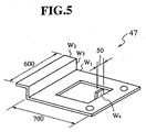
- a 3D perspective view 47 of the part with dimension lines for "600", “700” and “50” as shown in Fig. 5 and/or a 2D unfolded view 49 of the part with bending lines B1, B2, B3 as shown in Fig. 6A are displayed on the screen of the CRT 25b.
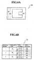
- a bending-order and tool table 51 as shown in Fig. 6B are displayed on the screen of the CRT unit 25b together with the foregoing views of the part. It should be noted that when the table initially appears on the screen of Fig. 6B, the bending line column, the tool column, and the tool length column are blank (not shown in the drawings).
- step S23 the operator refers to, for example, the 3D perspective view 47 as shown in Fig. 5 and the 2D unfolded view as shown in Fig. 6A and determines a bending order in which a workpiece is bent along the bending lines B1, B2 and B3. Moreover, the operator selects and determines tools (punches and dies) for bending the workpiece along the bending lines B1, B2 and B3. The determination of the bending order is performed by, for example, sequentially clicking the bending lines B1, B2 and B3 on the 2D unfolded view as shown in Fig. 6A with a mouse pointer and the like.
- each of the bending line numbers B1, B2, B3 are entered, in order of bending operation, into each line of the bending line column of the bending-order and tool table 51 as shown in Fig. 6B.
- Fig. 6B if the bending lines are bent in order of B3, B2 and B1, bending line B3 is entered into the first line for the bending order 1, bending line B2 entered into the second line for the bending order 2 and bending line B1 entered into the third line for the bending order 3.
- the operator determines tools for bending the workpiece along the bending lines B1, B2 and B3. Determination or selections of the tools are performed by, for example, entering suitable tool numbers into lines in the column for the tool number in Fig. 6B.
- punch P1 and die D1 are used for the bending along the bending lines B3 and B2, and punch P2 and die D2 used for the bending along the bending line B1.
- the data P1 and D1 indicate, for example, the punch number 402 and the die number 30286 (11) and, the data P2 and D2 indicate the punch number 14702 and the die number 30286 (10).
- a menu for available tools may be displayed on the screen of the CRT so that the operator can select a suitable tool from the menu.
- the lengths of the selected tools are determined and entered into the tool length column of the table 51.
- the length of punch P1 and die D1 835 mm is entered into the first and the second lines of the table, while 50 mm is entered into the third line thereof, as the length of the punch P2 and die D2, as shown in Fig. 6B.
- the bending-order and tool table 51 are entered into a memory of the terminal 25 by suitable operation at the keyboard 25c.
- step S24 the operator selects tools (punches and dies) from a die magazine while referring to the bending-order and tool table 51 on the CRT screen 25b. Then, the operator mounts and places the selected tools on the apron 37a and the ram 43 of the first bending press 21 by using his experience and skill.
- step S25 the operator enters into the terminal 25 data for the arrangement (or the layout) of the tools on the apron 37a and the ram 43.
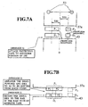
- a suitable key on the keyboard 25c is depressed, an image as shown in Fig. 7A appears on the screen of the CRT 25b.
- FIG. 7A Although omitted from the drawing, when the image of Fig. 7A initially appears on the screen, only figures showing the apron 37a and the ram 43, central position O and a direction symbol 53 are displayed, while the other figures and characters are not displayed.
- the operator enters symbols and/or figures of the punch P1 and die D1 into the terminal in such a manner, for example, that the central position of each figure (or image) of the tool is positioned away from the central position O by a distance of - 500 mm, as shown in Fig. 7A.
- front-side mounting or “reverse-side mounting” may be entered for each of the punch and the die; these information specify whether punch P1 and die D1 are mounted with the font-side facing forward or the reverse side facing forward.
- symbols and/or figures showing punch P2 and die D2 are entered in such a manner, for example, that the central position of each figure is positioned away from the press central position O by a distance of + 500 mm.
- the information, "front-side mounting” or “reverse-side mounting” that indicates whether punch P2 and die D2 are mounted with the front-side facing forward or the reverse side facing forward may also be entered.
- step S26 after the data for the arrangement of the tools are entered, the guide program generates a question whether there are additional hints that are useful for performing the tool set-up operation and that are worthwhile to be recorded. If the operator thinks of such hints, he enters the same into the terminal 25 as an operation support information. For example, when the punch and the die are mounted on the bending press, it is preferable to attach a tape to the shoulder portion of the die D1, D2 so that the dies D1, D2 are not flawed when attached on the ram 43. Thus, a message 1, "Attach a protection tape to the shoulder portion of the die" may be entered as a hint, as shown in Fig. 7A.
- the punch P1 and the die D1 are composed of small punches P5', P6' and diesD5', D6'
- step S27 an alignment of the punch and the die in the longitudinal direction (i.e. in the front and rear direction) of the press brake is performed.
- This operation is as follows.
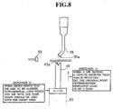
- the die 45 of the first bending press 21 is roughly or generally mounted on the ram 43 (or the rail of the ram) so as to be movable in the longitudinal direction (i.e. in the lateral direction in Fig. 8). Therefore, when the die 45 is initially mounted on the ram 43, the position of a bottom portion 45a of a recess of the die 45 is normally displaced in the longitudinal direction from the position of the apex 39a of the punch as shown in Fig. 8 .
- the longitudinal position of the die 45 is adjusted in the longitudinal direction so that the bottom portion 45a of the die 45 coincides with the apex 39a of the punch 39.
- This operation is called the alignment of the tools in the longitudinal direction.
- supplemental punch and die with the same shape and longer dimensions may be temporarily mounted on the rail of the ram43.
- step S28 after the alignment of the tools are performed, the operator enters an instruction on the execution of the alignment of the tool as operation support information. Then, the guide program generates a question whether there is hints that are useful for performing the alignment of the tool. If the operator thinks of such hints, he enters the same into the terminal 25 as additional operation support information. For example, the operator may input a hint that "When short punch and die are to be aligned, supplemental long punch and die with the same shape should be used with the short ones" is entered as a message 4, as shown in Fig. 8. The guide program may generate similar questions in the following steps whenever useful hints relating to those steps are to be entered although it may not be explicitly described hereinafter.
- an original-point determination operation (or an original-point adjustment operation) is performed.
- the original-point (or a reference point) is a position of the die 45 relative to the punch 39 in which position the die 45 is directly engaged to the punch 39 with a predetermined engaging force with no workpiece being held between the punch 39 and the die 45.
- the original-point determination operation is necessary for the reason as follows. That is, the bending angle of a workpiece bent by the punch and the die is generally determined by the distance moved by the die 45 relative to the punch 39 during bending operation. However, during the bending operation, the side frame 35 or the like of the bending press is deformed.
- the distance moved by the die 45 from a reference point determined in a condition where no engaging force is applied between the punch and die does not corresponds to the bending angle of the workpiece to be bent by the punch and the die. Therefore the position of the die 45 in the above-mentioned condition where a predetermined force acts between the punch and the die is determined as a correct original position (or a correct reference position) of the die 45.
- the load, which is applied between the punch and the die is selected in accordance with the length of the mounted die. That is, if a die having a length longer than a predetermined length is mounted, a load of 7 tons, for example, is applied between the punch and the die to determine the original point of the die.
- the load of 7 tons may break the punch and the die. Therefore, a 3 tons, for example, which is smaller than the durable pressure for the punch and the die is applied between the punch and the die to determine the original point of the die.
- the mounted die is longer than the predetermined length, and the load of 7 tons is applied between the punch and the die.
- step S30 an instruction for performing the original-point determination operation (or the original-point adjustment operation) and a hint relating to the original-point determination operation are entered and stored in the memory of the terminal 25 as operation support information.
- a message 5 "When a die having a length shorter than x mm is mounted, set the original-point determination operation load to be 3 tons " is entered as shown in Fig. 8.
- a program for performing following steps may be provided in the terminal 25: First, it retrieve the tool number and the length of the tool entered in step S23. When the tool is longer than a predetermined length, it generates a first message "Perform the original-point determination with 7 tons" is generated. On the other hand, when the die is shorter than the predetermined length, it generates the second message "Perform the original-point determination with 3 tons".
- steps S31, S32, S33 and S34 trial bending of a workpiece for manufacturing the part or the product as shown in Fig. 5 is performed.
- step S31 a trial bending operation number i for specifying each of bending operations is set as 1.
- step S32 the i-th trial bending operation is performed, and operation support information relating to the i-th bending are entered, as described in detail below.
- step S33 it is determined whether all of the trial bending operations have been completed. If they have not been completed, the step number i is increased by one in step S34, and then the operation returns to step S32. If all of the trial bending operations have been completed in step S33, the operation proceeds to step S35, where a plurality of workpieces are successively bent in the manner determined by the trial bending operations in step S32. During this successive bending operations, the bending accuracy is inspected each time a predetermined number of workpieces are processed. If the operation accuracy does not satisfy a predetermined requirement, values D and L, which is described later, are modified.
- step S36 the operator enters an operation support information about the frequency of checking of the bending accuracy; such checking is to be performed in subsequent bending operations, such as the operations shown in Figs. 12A and 12B. For example, an operation support information to inspect the accuracy for every ten workpieces is entered.
- step S37 a variety of information and data including the operation support information relating to the bending operation entered in steps S23, S24, S26, S28, S30, S32, S35 and S36 are transmitted from the terminal 25 to the server 31 together with the part number and the shape of the part, and they are all stored in the database 33 of the server 31.
- step S38 the bending operation for the new part is completed.
- Fig. 4 is a flow chart for showing in detail the i-th trial bending operation and operation of entering support information relating to the same, which are performed in step S32 in Fig. 3.
- step S41 a memory area is reserved under a number i in a memory of the terminal 25.
- the number i is set to be 1 since the i has been set to be 1 in step S31.
- step S42 in order to bend a workpiece along bending line B3 (Fig. 6A) through an angle of 90°, numerical control data D, L and Yz for the bending press 21 are entered into the terminal 25.
- the data D specifies the vertical position of the die 45 relative to the original position (or the reference position) Ho determined in step S29.
- the data L specifies the position of a back gauge device 55 in the longitudinal direction (i.e. in the lateral direction in Fig. 14) relative to a reference position which is, for example, the central position Yo of the die 45.
- the data Yz specifies the vertical position of the back gauge device 55 relative to a reference position, which is, for example, the top end of the die 45.
- the value D determines the bending angle of the workpiece W to be bent by the bending press 21, while the value L determines the width of the workpiece W between an edge E1 (see Fig. 9A) and the bending line B3.
- the value Yz is used to adjust the vertical position of the back gauge device 55 during bending operation. Specifically, the height of the back gauge device is adjusted to correspond to the height of a flange formed at the rear end of the workpiece (for example, flange W2 shown in Fig. 9B or Fig. 10B).
- a flange formed at the rear end of the workpiece for example, flange W2 shown in Fig. 9B or Fig. 10B.
- the back gauge device 55 is located in a vertical position lower than that as shown in Fig. 9A so as that the flange W2 is properly brought into contact with the back gauge device 55.
- step S42 the values D, L and Yz may be automatically calculated and entered on the basis of geometrical data of the part and tools and the bending order to be performed.
- the back gauge device 55 is moved by the control of the terminal 25 in the vertical and longitudinal directions to a position determined by such data.
- step S43 the workpiece W is inserted between the punch 39 and the die 45, and the rear end thereof is brought into contact with the back gauge device 55 to position the same with respect to the punch and die. Thereafter, the first trial bending is performed on the workpiece W along the bending line B3.
- step S44 on the basis of the trial bending operation performed in step S43, operator enters operation support information in relation to the positioning of the workpiece W relative to the punch and die.
- These operation support information includes hints relating to the positioning of the workpiece.
- a figure showing the tools P1, D1 on bending press 21 and the workpiece W appears on the screen of the CRT 25b in response to a completion signal from the bending press 21.
- a sound buzzer and the like may be provided.
- the operator moves to a position in front of the terminal 25.
- the punch P1 and the die D1 on the bending press 21 should be used to perform the bending operation (see Fig. 6B).
- the color of the figures of the punch P1 and D1 is changed into gray as shown in Fig. 9A,.
- information concerning positioning of the workpiece W with respect to the punch and die is entered.
- the figure or image of the workpiece W on the CRT screen is moved translationally and rotationally to a position in front of the punch P1 and the die D1, as shown in Fig. 9A.
- This movement of the figure of the workpiece can be carried out by using a mouse (not shown) or a joystick (not shown) connected to the terminal 25.
- the edge E1 of the workpiece W is brought into contact with the back gauge device 55, and the bending operation is performed along the bending line B3. Therefore, the figure of the workpiece W is located in a attitude as shown in Fig. 9A with respect to the figure of the punch P1 and die D1.
- the operator may enter the messages 6 and 7 relating to the positioning of the face of the workpiece W as hints.
- the message 6 "Insert the workpiece between the punch and die in a manner that its sheet surface faces upwards" is a hint for specifying the surface of the workpiece W to be inserted between the tool.
- the "sheet surface” means a surface of the workpiece on which a vinyl sheet is attached; the vinyl sheet is normally attached on that surface to protect that surface from being scratched during transportation.
- the message 6 is important because the bending operation should be performed so that the sheet surface forms outside surface of the part or product which should have a fine appearance.
- the message 6 is important when the shape of the workpiece has some symmetry so that the sheet surface cannot be determined in the image of the workpiece displayed on the CRT 25b.
- the surface of the workpiece can also be designated by specifying the directions of burrs formed on the workpiece. In this case, a message, for example, "Locate the workpiece in such a manner that the direction of burrs face downward" is entered.
- the message 7, "Securely bring the workpiece into contact with right and left back gauge devices" is a hint for reminding the operator to securely engaging the rear end of the workpiece with the right and left back gauge devices 55 when the workpiece W is inserted between the punch and die.
- This message 7 is entered because a precise bending cannot be achieved if either one of the back gauge devices fails to contact the rear end of the workpiece. After these information are entered and displayed on the CRT 25b, all data are stored in a memory of the terminal 25.
- step S45 the operator determines in accordance with the result of the trial bending operation whether buckling of the workpiece has occurred during first trial bending operation or whether the buckling of the workpiece could occur during the first bending operation during the successive bending operation in step S35. If an affirmative determination is made, the operation proceeds to step S46.
- step S46 the operator enters an instruction to support the end of the workpiece W from a lower position during the bending operation as a operation support information (see message 6a shown in Fig. 9A).
- step S47 the part manufactured by the trial bending operation is inspected. Specifically, the operator measures the length and angle of a flange W 2 formed by the first bending operation.
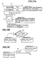
- the operator After the measurement has been carried out, the operator enters into the terminal an instruction or a hint for specifying dimensions and angles to be measured and together with their tolerances, as operation support information in step S48. Specifically, as shown in Fig. 9B, when the shape of the workpiece W including the flange W2 formed by the trial bending operation is displayed on the screen of the CRT 25b, the operator enters symbols relating the length "L1" of the flange W2 and symbols relating the angle " ⁇ 1" of the same as an operation support information. Moreover, a message 8 "Check that height L1 is 15 mm ( ⁇ 0.1 mm)" and a message 9 "Check that angle ⁇ 1 is 90° ( ⁇ 10')" are entered.
- the shape of the flange W2 may be displayed in the form of a cross sectional view, as shown in Fig. 9C.
- the fact that the height L1 of the flange is a dimension including the thickness of bottom surface portion W1 of the workpiece W can be more easily understood.
- a message "Note that the dimension L1 includes the thickness of the bottom surface portion W1" may be added to the display in Fig. 9B or 9C.
- step S49 the operator determines whether the dimension L1 and the angle ⁇ 1 are within a required tolerance. For example, it is determined whether the dimension L1 is within a range of 15 mm ⁇ 0.1 mm. If it is determined in step S49 that the dimension L1 is not within the range, either or both of the values D and L are modified in step S50. Then, the operation returns to step S43 so that the trial bending operation is again performed.
- step S49 If the dimension L1 and the angle ⁇ 1 are within the required range in step S49, the foregoing data D, L and Yz are stored in step S51 in the memory area under the number i.
- step S44 the figure of the workpiece W that has been bent along the bending line B3 is displayed on the screen of the CRT 25c together with the bending press 21, as shown in Fig. 10A.
- the punch P1 and the die D1 are again used to perform the bending operation along the bending line B2. Therefore, the figures of the punch P1 and the die D1 are displayed in gray, as shown in Fig. 10A.
- the back gauge device 55 is brought into contact with the flange W2 formed in the first bending operation. Therefore, as shown in Fig. 10A, the figure of the back gauge device 55 is moved to a position lower than that of the back gauge device 55 in Fig. 9A.
- the figure of the workpiece W is suitably moved until it has an attitude (or an orientation) that the edge E2 faces toward the punch P1 and the die D1, as shown in Fig. 10A.
- the workpiece W is bent along the bending line B2 in a direction opposite to that in the first bending operation. Therefore, a message 10, "Insert the workpiece W in such a manner that the sheet surface faces downwards" is entered.
- data of a perspective view of the backgauge 55 and the partially bent workpiece W positioned relative to the backgauge 55 may be entered in place of the message 10. Then, all the information shown in Fig. 10A are stored in a suitable memory of the terminal 25.
- step S48 of the second trial bending operation the shape of the workpiece including the flange W2 formed in the first trial bending operation and the flange W3 formed in the second trial bending operation is displayed, as shown in Fig. 10B. Therefore, the operator enters figures or symbols relating the dimension L2 and the angle ⁇ 2, which must be measured in relation to the flange W3, as shown in Fig. 10B. Moreover, messages 11 and 12 relating to measurement of the dimension L2 and the angle ⁇ 2 are entered.
- the shape of the workpiece including the figures or symbols relating the dimension L2 and the angle ⁇ 2 may be displayed in the form of a cross sectional view, as shown in Fig. 10C. This view clearly shows that the dimension L2 includes the thickness of the flange W2 and the base portion W1.
- step S44 the shape of the workpiece W that has been subjected to the first and second bending operations is displayed together with the punches and dies of the press 21 on the screen of the CRT 25b, as shown in Fig. 11A.
- the punch P2 and the die D2 are used for the bending operation. Therefore, the punch P2 and the die D2 are displayed in gray.
- the figure showing the back gauge device 55 is moved to positions around the punch P2 and the die D2. Then, the operator moves the figure showing the workpiece W until the end E3 faces the punch P2 and the die D2, as shown in Fig. 11A.
- step S48 of the third trial bending operation the shape of the workpiece W that has the flange W2 formed in the first bending operation, the flange W3 formed in the second bending operation and the flange W4 formed in the third bending operation is displayed, as shown in Fig. 11B or Fig. 11C. Then, the operator inputs symbols relating to width L3 and angle ⁇ 3 relating to the flange W4 formed in the third trial bending operation and messages 14 and 15 relating to measurement of these dimensions. Further, in case where a workpiece has, for example, a slanted rear edge, a suitable jig is preferably attached to the backgauge 55 to position the workpiece.
- the operator may input a message such as "Attach a jig X to the backgauge". Together with this message or instead of this message, the operator may input data of images or views of the backgauge and the jig attached to the backgauge.
- a skilled operator stores into the terminal computer 25 the operation information for efficiently performing a trial bending operation on the part, as operation support information or guide information or hints, while performing the trial bending operations. Moreover, the operation information is transmitted to and stored in the database 33 of the server 31. Therefore, if the same or similar part is ordered later, the operation information stored for each part is retrieved from the database 33 so that an optimum operation for manufacturing the ordered part is performed easily and quickly. In particular, even an operator without skill can perform a necessary bending operation easily and quickly by referring to the operation information above.
- a guide program for guiding a new bending operation is activated (see step S21) when an operator enter into the terminal 25 an instruction for the new bending operation.
- the terminal 25 urges the operator to enter suitable information including operation support information relating to set-up operation (preparation operation) and the bending operation when an operator has completed the actual set-up operation and bending operation. Therefore, the operator can securely enter suitable information including the operation support information.
- step S37 the variety of the information that relates to the bending operation for the new part and that are entered in steps S23, S25, S26, S28, S30, S32 (including steps S42, S44, S46, S48, S50 and S51) and step S36 are stored in the database 33 of the server 31 together with the part number and the shape of the part.
- Tables 1 to 5 show a manner in which the foregoing various information including the operation support information are stored in the database 33.
- part file specified by a part identifying data (refereed to hereinafter as "part ID") such as the part number for specifying a part.
- part ID a part identifying data
- the part file has a file for shape, a file for set-up operation and a file for bending operation.
- the file for the shape stores data for the shape as shown in Figs. 5 and 6A.
- the file for the set-up operation has a file for the bending order, a file for the tools, a file for the tool layout, a file for the alignment of the tools and a file for the original-point determination operation
- the file for the bending order stores bending order data shown in Fig. 6B or Table 3
- the file for the tools or dies stores data of the dies shown in Fig. 6B or Table 4
- the file for the tool or die layout stores data for the layout of the die shown in Fig. 7A and Fig. 7B
- the file for the alignment of tools stores data of the image and the message 4 shown in Fig.
- the file for the bending operation stores bending operation data as shown in Table 5. That is, data for symbols and figures as shown in Fig. 9A and Fig. 9B (or Fig. 9C) and data of D1, L1 and Yz1 for the D, L and Yz as shown in Fig. 14 are stored in relation to the bending line number B1. In relation to the bending line number B2, data for symbols and figures as shown in Fig. 10A and Fig. 10B (or Fig. 10C) and data of D2, L2 and Yz2 for the D, L and Yz are stored. In relation to the bending line number B3, data for the symbols and figures as shown in Fig. 11A and Fig. 11B (or Fig.
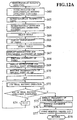
- Fig. 12A is a detailed flow chart of step S13 shown in Fig. 2
- Fig. 12B is a detailed flow chart of step S72 shown in Fig. 12A.
- the repeat/similar bending operation is supposed to be performed at the second bending station 22 in Fig. 1.
- step S10 an operator at the second bending station 22 reads the bar code attached to an operation instruction sheet by using the bar code scanner 27a. Then, bending operation data for manufacturing an ordered part, which is the same as or similar to the part stored in the database 33 of the server 31, is retrieved to the terminal 27.
- step S11 if it is determined that the ordered part is not a new part (that is, if the database 33 includes bending operation data for one or more parts that are the same as or similar to the ordered part), the operation proceeds to step S13 and more specifically to step S61 in Fig. 12A.
- step S61 a guide program for guiding the operator in performing the repeat/similar bending operation is activated.
- step S62 a perspective view of the ordered part and that of a part that is the same as or similar to the ordered part are retrieved and displayed on the CRT screen 27b as shown in Fig. 5; here, a statement that the ordered part is the same as or similar to the part or parts, data of which have been stored in the database 33, may be simultaneously displayed on the CRT screen 27b (not shown).
- the shape of the ordered part and the shape of the similar part are simultaneously displayed on the CRT screen 27b.
- the shapes of the ordered part and of the similar part differs from each other slightly, for example, in width of the flange W2 as shown in Fig. 5. Then, the operator observes the perspective views of the parts to confirm the shape of the part to manufacture.
- step S63 the operator depresses an suitable key on the keyboard 27c so that data of the unfolded views of the ordered part (and that of the similar part), data of the bending order for manufacturing the part and data of the tool numbers to be used are retrieved and displayed on the screen, as shown in Figs. 6A and 6B.
- the operator can easily confirm the unfolded views of the parts, the bending order and the tools or dies to be used.
- step S64 the operator selects necessary tools (i.e. punches and dies) P1, D1, P2 or D2 from an suitable die magazine by referring to the tools displayed on the screen 27b.
- necessary tools i.e. punches and dies
- step S65 the operator again depresses an suitable key on the keyboard 27c so that the layout (arrangement) of the tools on the second bending press 23 and hints for arranging the tools are displayed on the screen as operation support information, as shown in Fig. 7A and Fig. 7B.
- step S66 the operator mounts and places selected tools on the bending press 23 by referring to the tool arrangement displayed on the CRT screen 27b in step S65.
- step S67 the operator depresses an suitable key on the keyboard so that the cross sectional shape of the tools, the instructions (not shown) for performing the alignment of the tools and the operation support information or hints relating to the alignment of the tools (such as the message 4) are displayed on the screen 27b, as shown in Fig. 8.
- step S68 the operator aligns the tools on the bending press 23 by referring to the figures and statements displayed on the screen 27b.
- step S69 the operator again depresses an suitable key on the keyboard 25c so that the cross sectional view of the tools, the instruction (not shown) for determining the original point of the die and hints for performing original-point determination (such as the message 5) are displayed on the screen, as shown in Fig. 8.
- step S70 the operator performs the determination of the original-point of the die in the bending press 23 while referring to information displayed on the screen 27b in step S69.
- step S71 where the bending operation number i is set to 1.
- step S72 the operator performs an i-th trial bending operation on a workpiece referring to operation support information for the i-th trial bending operation displayed on the screen of the CRT 27b.
- step S73 it is determined whether all of the trial bending operations have been completed. If all of the trial bending operations have not been completed, the bending operation number i is increased by one at step S74, and the process returns to step S72.
- step S73 If all of the trial bending operations have been completed in step S73, the operation proceeds to step S75.
- step S75 the frequency for checking the accuracy of the bending operations to be carried out during successive bending operation performed in step S76 is displayed on the screen. For example, an instruction to check the accuracy for every 10 workpieces is displayed on the screen of the CRT 27b.
- step S76 the operator successively bends a plurality of workpieces in accordance with the trial bending operations performed in step S72 so as to manufacture the plurality of the ordered parts.
- the operator follows the instructions displayed in step S75 and check the bending accuracy each time 10 parts are processed. If the processing accuracy does not satisfy a predetermined tolerance, the value L and value D are modified.
- step S77 the value L and the value D modified in step S76 are stored in the database 33 through the terminal 27.
- step S78 the repeat/similar being process is completed.
- Fig. 12B is a flow chart showing details of the i-th trial bending operation performed in step S72 shown in Fig. 12A.
- step S71 When the operator sets the bending operation number i to 1 in step S71, the process proceeds to step S80, where information for positioning the workpiece W relative to the tools P1 and D1 and the hints relating to the operation for locating the workpiece are displayed as operation support information on the screen of the CRT 27b, as shown in Fig. 9A.
- step S81 the operator locates the workpiece W with respect to the punch P1 and the die D1 by referring to the display on the screen. Moreover, the workpiece W is located so that the bending line B3 of the workpiece W is positioned between the punch P1 and the die D2.
- the position of the back gauge device 55 is located to a predetermined height in the rear of the punch P1 and the die D1 in accordance with the data of L and Yz retrieved from the database 33.
- the position of the back gauge device 55 in the longitudinal direction (that is, the value of L) is somewhat modified in step S81 in accordance with the actual width of the flange W2 of the ordered part (as described above, it is supposed here that the length of the flange W2 of the ordered part is somewhat different from the length of the flange W2 of the similar part stored in the database 33).
- step S82 the operator executes the ith trial bending operation on the workpiece W along the bending line B3.
- step S83 the shape of the workpiece formed with the flange W2 as well as the figures (and instructions) relating to the dimension L1 and angle ⁇ 1 to be measured for inspection of the bending accuracy are displayed on the screen of the CRT 27b, as shown in Fig. 9B or 9C.
- step S84 the operator inspects or measures the dimension L1 and the angle ⁇ 1 of the workpiece by referring to the dimension and the angle displayed on the screen.
- step S85 it is determined whether the dimension L1 and the angle ⁇ 1 are within a predetermined tolerance. If the predetermined tolerance is not satisfied, the value D and the value L are modified in step S86 and in step S87, the i-th trial bending operation is completed.
Description
- The present invention relates to a method of manufacturing a product or a part with a predetermined shape by using a bending press as well as to a bending station for carrying out the method according to the preambles of
claims 1 and 17 respectively (see for example US-A-5 029 462). - When various parts or products with complicated shapes are manufactured by performing one or more bending operations, various preparation steps have to be carried out before the actual bending operations are performed. Examples of such preparation steps are as follows: determining the order of bending operations along bending lines; arranging bending tools (or dies) on a bending press; and adjusting the positions of the bending tools (or dies) in the bending press. In fact, conventionally, enormous working hours has been wasted to carry out these preparation steps. Further, when a bending operation for manufacturing a specific product has been finished, the data concerning the preparation steps has been thrown away. Thus, even when products that are the same as or similar to the previous product are manufactured later, the preparation steps had to be carried out again.
- The object of the present invention is to solve the foregoing problems of the conventional method and system.
- Specifically, the object of the present invention is to provide a method and a system for bending operation in which various data concerning preparation steps for a particular bending operation are suitably stored in a memory so that they can be used in a subsequent bending operations for manufacturing parts having the same shape or similar shapes.
- Another object of the present invention is to provide a method or a system by which an operator without skills in performing bending operations can easily and quickly perform precise bending operations on a workpiece by following skilled operator's experience, hints, or data.
- To achieve the foregoing objects the present invention provides a method for manufacturing a product or a part with a predetermined shape by using a bending press and a bending station with the features of
claims 1 and 17 respectively. - In accordance with the present invention, various optimum steps (or procedures) relating to the bending operations, which are carried out by a skilled operator for manufacturing a predetermined part or a product, are stored in a computer memory as operation support information for each part. Therefore a non-skilled operator can learn, from the computer memory, the stored optimum operation support information for each part or product later and easily and quickly perform the optimum steps (or procedures) for manufacturing the part or the product by following the skilled operator. That is, even a non skilled operator can quickly start the bending operation without taking an excessively long time for standby operations (or preparation steps) for manufacturing the part or product.
- The term "part" in this specification means a product that is to be distributed in a market as well as a portion of that product.
-
- Fig. 1 is a block diagram of an embodiment of a plate bending system including the bending station according to the present invention;
- Fig. 2 is a flow chart of the overall operation of the plate bending system shown in Fig. 1;
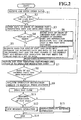
- Fig. 3 is a flow chart showing a detailed operation of a step in the flow chart shown in Fig. 2, and specifically showing the operation of a step for manufacturing a new part or product in Fig. 2;
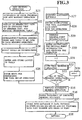
- Fig. 4 is a flow chart showing a detailed operation of a step in the flow chart shown in Fig. 3, and specifically showing the operation of a step for performing an i-th bending operation on the plate material to manufacture the new part in Fig. 3;
- Fig. 5 is a schematic view showing a part displayed on the screen of a terminal computer in step S22 in Fig. 3;
- Fig. 6A and Fig. 6B respectively are a 2D unfold view of the shape of the part and a view of a table that shows bending lines and tools to be used, both the views being displayed on the screen of the terminal computer in step S23 shown in Fig. 3;
- Fig. 7A and Fig. 7B are views showing layout of tools to be used and operation support information relating to the layout, the views being displayed on the screen of the terminal computer in step S25 and step S26 in Fig.3;
- Fig. 8 is a cross sectional view of a die and a back gauge device that are displayed on the screen of the computer terminal in relation to a alignment operation and an original-point determination operations in steps S28 and s30 in Fig. 3;
- Fig. 9A, Fig. 10A and Fig. 11A are schematic views showing attitudes of a workpiece with respect to tools in a bending press and operation support information relating to positioning of the workpiece with respect to the bending press, which are displayed on the screen of the terminal computer in step S44 in Fig. 4;
- Fig. 9B, Fig. 10B and Fig. 11B are schematic views showing the parts with dimensions data and operation support information relating to the inspection of the dimensions, which are displayed on the screen of the terminal computer in step S48 in Fig. 4;
- Fig. 9C, Fig. 10C and Fig. 11C are other schematic views showing the parts with dimension data and operation support information relating to the inspection of the dimensions, which are displayed on the screen of the terminal computer in step S48 in Fig. 4.;
- Fig. 12A is a flow chart showing a detailed operation of a portion of the operation shown in the flow chart of Fig. 2, and specifically the flow chart showing the operation when the same or a similar part is manufactured in Fig. 2;
- Fig. 12B is a flow chart showing a detailed operation of a portion of the operation shown in flow chart of Fig. 12A, and specifically the flow chart showing the operation for performing an i-th trial bending operation on a sheet metal in Fig. 12A;
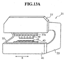
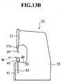
- Fig. 13A and Fig. 13B respectively are a perspective schematic view and a schematic cross sectional view of a bending station according to an embodiment of the present invention; and
- Fig. 14 is an explanatory view for explaining value D, value L and value Yz in a press brake acting as the bending press.
- Examples of the present invention will now be described with reference to the drawings.
- Fig. 1 is a block diagram of a plate bending system including bending stations according to the present invention. As shown in Fig. 1, the plate bending system according to this embodiment includes a
factory office 30 for receiving from a customer an order for manufacturing a part or a product (a bent workpiece) with a predetermined shape and a plurality ofbending stations bending stations factory office 30 instructions to manufacture the ordered part or product. - The
factory office 30 is provided with a server computer (hereinafter called a "server") 31 having adatabase 33. Thedatabase 33 in theserver 31 stores a variety of data about parts which have been manufactured by the bending system, as will be described later in detail. A bar-code preparation apparatus 31a for preparing bar codes is connected to theserver 31. - The
first bending station 20 of thebending stations first bending press 21 such as a press brake and a first computer terminal 25 (hereinafter called a "terminal for a press" or simply called a "terminal"). Theterminal 25 includes an NC unit for controlling thefirst bending press 21. - As shown in Figs. 13A and 13B, the
first bending press 21 includes, for example, a C-shape frame 35. Anapron 37a is provided on anupper support plate 37 of the C-shape frame 35, and a plurality ofpunches 39 are disposed at the lower end of anapron 37a along a straight line running in the x-axis direction. Moreover, aram 43, which is movable vertically, is supported by alower support plate 41 of the C-shape frame 35. A plurality of dies 45 for bending a plate (hereinafter called a "workpiece") W in cooperation with thepunches 39, are disposed at the top end of theram 43 along a straight line running in the x-axis direction. When the workpiece is inserted between thepunches 39 and the dies 45 and then theram 43 is moved upwards, thepunches 39 and the dies 45 are mutually engaged to one another so that the workpiece W held therebetween is bent upward. - Again referring to Fig. 1, connected to the terminal 25 are a
keyboard 25c for entering data into the terminal 25, a CRT unit (hereinafter called a "CRT") 25b serving as a display unit for displaying data supplied from the terminal 25 and a bar-code reading unit (bar code scanner) 25a for reading bar codes made by the bar-code preparation apparatus 31a and providing the read bar code data to the terminal 25. Here, data can be entered into the terminal 25 by using touch keys provided on the CRT screen as well as thekeyboard 25c. - Similarly to the first bending
station 20, thesecond bending station 22 is provided with asecond bending press 23 and asecond computer terminal 27. Akeyboard 27c, a CRT 27b and a bar-code reading unit 27a are connected to the terminal 27. Theserver 31 of thefactory office 30 and theterminals stations network 29 to one another so as to allow mutual data communication therebetween. - Referring to Fig. 2, the overall operation of the plate bending system will now be described.
- In step 81, various data concerning ordered part are received by the
factory office 30. Such data contains, for example, the part number of the ordered part and data on the shape of the part. The part number is, for example, a combination of symbols and numerals, such as "PT123a". The symbol "PT" indicates the ordered part being a part of a complete product, and the numeral "123" specifies the type of the part, and the symbol "a" specifies the dimensions of the part specified by "123". The data on the shape of the part consists of data for a 3D perspective view of the ordered part, data for a 2D unfolded view of the same or data for 2D, three views of the same; the 2D, three views consist of a front view, a plan view and a side view. In step S1, such data for the ordered part are entered into theserver 31. - In step S2, the
server 31 performs one or more searches on the basis of the entered part number to see whether bending operation data for the part that is the same as the ordered part is stored in thedatabase 33. - When no data on the same part is in the
database 33, an operator enters into theserver 31 the data on the shape of the ordered part in step S3. The data on the shape entered in step S3 consists of data concerning a 3D perspective view of the ordered part, data concerning a 2D unfolded view of the same or 2D three views of the same. When data on one of the views are entered, theserver 31 calculates data on two other views on the basis of the entered data by a predetermined calculation method. For example, if data for the 2D three views are entered, theserver 31 calculates data for the 3D perspective view and 2D unfolded view. - In step S4, the
server 31 carries out a search on the basis of the part number to see whether data for bending operations for parts similar to the ordered part (i.e. similar parts) are stored in thedatabase 33. For example, when the part number of the ordered part is "PT123a", a search is carried out to see whether thedatabase 33 includes data for the parts designated by part numbers "PT123b", "PT123c" and "PT123d" and the like. - If it is detected in step S4 that the data for the similar parts is stored in the
database 33, the operation proceeds to step S5, where data for the similar parts are retrieved from thedate base 33. Moreover, in step S5, the retrieved data, data on the shape of the ordered part, and the part number of the ordered part are stored into thedatabase 33 together with information indicating the associated data is for a similar part. That is, in step S5 the operator stores into thedatabase 33 the retrieved data, the part number of the ordered part, data on the shape of the ordered part, and the data indicating that the retrieved data item is data for a similar part, as a set of data. - If no part number of a similar part is detected in step S4, the operation proceeds to step S6. In step S6, the data on the shape of the ordered part and the part number of the ordered part are stored in the
database 33 together with data indicating that the ordered part is a new part. That is, in step S6, theserver 31 stores in thedatabase 33 the data indicating that the ordered part is a new part, the part number of the ordered part, and the shape of the ordered part as a set of data. - In step S2, if the same part number as the part number of the ordered part is detected, the operation directly proceeds to step S7.
- In step S7, the bar-
code preparation apparatus 31a connected to theserver 31 prepares a bar code sheet that specifies the part number of the ordered part. The prepared bar code sheet is attached to an operation instruction sheet to be delivered to bendingstations - In step S8, it is determined whether data of all of the ordered parts has been processed. When all data have not yet been processed, the operation returns to step S1. If the process has been completed, the operation proceeds to step S9.
- In step S9, the
factory office 30 assigns and delivers the operation instruction sheets to the bendingstation 20 or the bendingstation 22 in accordance with the skill of the operator at each bendingstation - When the operation instruction sheet is received by each of the bending
stations code reading unit database 33 and transmitted to either one of theterminals - In step S11, it is determined whether the assigned part is a new part, in other words whether the bending operation is for a new part. When the assigned part is a new part, the operation proceeds to step S12. In step S12, a new bending operation or new-part bending operation is performed as described in detail in the following with reference to Figs. 3 and 4. On the other hand, when the ordered part is the same or a similar part, the operation proceeds to step S13, where a repeat (reiteration process) or a similar bending operation is performed as described in detail in the following with reference to Figs. 12A and 12B. Then, the operation proceeds to step S14, where the overall operation is completed.
- Referring now to Fig. 3, the new-part bending operation performed in step S12 will be described in detail. It is supposed that the new-part bending operation is performed in the first bending
station 20. - As described above, when the assigned part is a new part, the data that the terminal 25 retrieves in step S10 of Fig. 2 includes the part number of the ordered part, data for the shape of the part (i.e. data of the 2D three views, the 3D perspective view or the 2D unfolded view) and information indicating that the part is a new part.
- If, in step S11 of Fig. 2, it is determined that the ordered part is a new part, the operation proceeds to step S21, where a guide program for a new bending operation is activated, the function of the guide program being described in detail in the following.
- In step S22, in accordance with the guide program, the shape of the ordered part as well as the part number of the ordered part and information indicating that the ordered part is a new part are displayed on the screen of the
CRT 25b. For example, a3D perspective view 47 of the part with dimension lines for "600", "700" and "50" as shown in Fig. 5 and/or a 2D unfoldedview 49 of the part with bending lines B1, B2, B3 as shown in Fig. 6A are displayed on the screen of theCRT 25b. Moreover, a bending-order and tool table 51 as shown in Fig. 6B are displayed on the screen of theCRT unit 25b together with the foregoing views of the part. It should be noted that when the table initially appears on the screen of Fig. 6B, the bending line column, the tool column, and the tool length column are blank (not shown in the drawings). - In step S23, the operator refers to, for example, the
3D perspective view 47 as shown in Fig. 5 and the 2D unfolded view as shown in Fig. 6A and determines a bending order in which a workpiece is bent along the bending lines B1, B2 and B3. Moreover, the operator selects and determines tools (punches and dies) for bending the workpiece along the bending lines B1, B2 and B3. The determination of the bending order is performed by, for example, sequentially clicking the bending lines B1, B2 and B3 on the 2D unfolded view as shown in Fig. 6A with a mouse pointer and the like. As a result, each of the bending line numbers B1, B2, B3 are entered, in order of bending operation, into each line of the bending line column of the bending-order and tool table 51 as shown in Fig. 6B. For example, as shown in Fig. 6B, if the bending lines are bent in order of B3, B2 and B1, bending line B3 is entered into the first line for thebending order 1, bending line B2 entered into the second line for thebending order 2 and bending line B1 entered into the third line for thebending order 3. - Then, the operator determines tools for bending the workpiece along the bending lines B1, B2 and B3. Determination or selections of the tools are performed by, for example, entering suitable tool numbers into lines in the column for the tool number in Fig. 6B. In the example shown in Fig. 6B, punch P1 and die D1 are used for the bending along the bending lines B3 and B2, and punch P2 and die D2 used for the bending along the bending line B1. Thus, data of P=P1 and D = D1 are entered into each of the lines for bending lines B3 and B2, and data of P = P2 and D = D2 are entered into the line for bending line B1. Specifically, the data P1 and D1 indicate, for example, the punch number 402 and the die number 30286 (11) and, the data P2 and D2 indicate the punch number 14702 and the die number 30286 (10). To assist the selection of the tools, a menu for available tools may be displayed on the screen of the CRT so that the operator can select a suitable tool from the menu.
- Then, the lengths of the selected tools are determined and entered into the tool length column of the table 51. For example, as the length of punch P1 and die D1, 835 mm is entered into the first and the second lines of the table, while 50 mm is entered into the third line thereof, as the length of the punch P2 and die D2, as shown in Fig. 6B. Then, the bending-order and tool table 51 are entered into a memory of the terminal 25 by suitable operation at the
keyboard 25c. - In step S24, the operator selects tools (punches and dies) from a die magazine while referring to the bending-order and tool table 51 on the
CRT screen 25b. Then, the operator mounts and places the selected tools on theapron 37a and theram 43 of thefirst bending press 21 by using his experience and skill. - In step S25, the operator enters into the terminal 25 data for the arrangement (or the layout) of the tools on the
apron 37a and theram 43. For this purpose, when a suitable key on thekeyboard 25c is depressed, an image as shown in Fig. 7A appears on the screen of theCRT 25b. Although omitted from the drawing, when the image of Fig. 7A initially appears on the screen, only figures showing theapron 37a and theram 43, central position O and adirection symbol 53 are displayed, while the other figures and characters are not displayed. After the foregoing screen is displayed, the operator enters symbols and/or figures of the punch P1 and die D1 into the terminal in such a manner, for example, that the central position of each figure (or image) of the tool is positioned away from the central position O by a distance of - 500 mm, as shown in Fig. 7A. - Moreover, description, "front-side mounting" or "reverse-side mounting" may be entered for each of the punch and the die; these information specify whether punch P1 and die D1 are mounted with the font-side facing forward or the reverse side facing forward. Likewise, symbols and/or figures showing punch P2 and die D2 are entered in such a manner, for example, that the central position of each figure is positioned away from the press central position O by a distance of + 500 mm. The information, "front-side mounting" or "reverse-side mounting" that indicates whether punch P2 and die D2 are mounted with the front-side facing forward or the reverse side facing forward may also be entered.
- In step S26, after the data for the arrangement of the tools are entered, the guide program generates a question whether there are additional hints that are useful for performing the tool set-up operation and that are worthwhile to be recorded. If the operator thinks of such hints, he enters the same into the terminal 25 as an operation support information. For example, when the punch and the die are mounted on the bending press, it is preferable to attach a tape to the shoulder portion of the die D1, D2 so that the dies D1, D2 are not flawed when attached on the
ram 43. Thus, amessage 1, "Attach a protection tape to the shoulder portion of the die" may be entered as a hint, as shown in Fig. 7A. Further, if the punch P1 and the die D1, for example, respectively are composed of small punches P5', P6' and diesD5', D6', it is preferable to preliminary secure the small dies D5', D6' to a rail (not shown) of theram 43 with an adhesive tape; further it is preferable that the small punches P5', P6' and dies D5', D6' are arranged on the rail of the ram so as to be laterally shifted from each other, as shown in Fig. 7B. Thus, additional hints, such asmessage 2, "Secure the small dies to the rail of the ram with an adhesive tape" andmessage 3, "Arrange the small punches and dies so as to be shifted from each other" are entered into the terminal, as shown in Fig. 7B. - In step S27, an alignment of the punch and the die in the longitudinal direction (i.e. in the front and rear direction) of the press brake is performed. This operation is as follows. As shown in Fig. 8, the
die 45 of thefirst bending press 21 is roughly or generally mounted on the ram 43 (or the rail of the ram) so as to be movable in the longitudinal direction (i.e. in the lateral direction in Fig. 8). Therefore, when thedie 45 is initially mounted on theram 43, the position of abottom portion 45a of a recess of the die 45 is normally displaced in the longitudinal direction from the position of the apex 39a of the punch as shown in Fig. 8 . As a result, before bending operation, the longitudinal position of the die 45 is adjusted in the longitudinal direction so that thebottom portion 45a of the die 45 coincides with the apex 39a of thepunch 39. This operation is called the alignment of the tools in the longitudinal direction. Here, when the lengths of the punch and the die are too short to precisely align the tools, supplemental punch and die with the same shape and longer dimensions may be temporarily mounted on the rail of the ram43. - In step S28, after the alignment of the tools are performed, the operator enters an instruction on the execution of the alignment of the tool as operation support information. Then, the guide program generates a question whether there is hints that are useful for performing the alignment of the tool. If the operator thinks of such hints, he enters the same into the terminal 25 as additional operation support information. For example, the operator may input a hint that "When short punch and die are to be aligned, supplemental long punch and die with the same shape should be used with the short ones" is entered as a
message 4, as shown in Fig. 8. The guide program may generate similar questions in the following steps whenever useful hints relating to those steps are to be entered although it may not be explicitly described hereinafter. - In step S29, an original-point determination operation (or an original-point adjustment operation) is performed. The original-point (or a reference point) is a position of the die 45 relative to the
punch 39 in which position thedie 45 is directly engaged to thepunch 39 with a predetermined engaging force with no workpiece being held between thepunch 39 and thedie 45. The original-point determination operation is necessary for the reason as follows. That is, the bending angle of a workpiece bent by the punch and the die is generally determined by the distance moved by the die 45 relative to thepunch 39 during bending operation. However, during the bending operation, theside frame 35 or the like of the bending press is deformed. Thus, the distance moved by the die 45 from a reference point determined in a condition where no engaging force is applied between the punch and die does not corresponds to the bending angle of the workpiece to be bent by the punch and the die. Therefore the position of the die 45 in the above-mentioned condition where a predetermined force acts between the punch and the die is determined as a correct original position (or a correct reference position) of thedie 45. It should be noted here that the load, which is applied between the punch and the die, is selected in accordance with the length of the mounted die. That is, if a die having a length longer than a predetermined length is mounted, a load of 7 tons, for example, is applied between the punch and the die to determine the original point of the die. However, if a die shorter than a predetermined length is mounted, the load of 7 tons may break the punch and the die. Therefore, a 3 tons, for example, which is smaller than the durable pressure for the punch and the die is applied between the punch and the die to determine the original point of the die. In the present embodiment, it is supposed that the mounted die is longer than the predetermined length, and the load of 7 tons is applied between the punch and the die. - In step S30, an instruction for performing the original-point determination operation (or the original-point adjustment operation) and a hint relating to the original-point determination operation are entered and stored in the memory of the terminal 25 as operation support information. For example, a
message 5, "When a die having a length shorter than x mm is mounted, set the original-point determination operation load to be 3 tons " is entered as shown in Fig. 8. In place of entering themessage 5, a program for performing following steps may be provided in the terminal 25: First, it retrieve the tool number and the length of the tool entered in step S23. When the tool is longer than a predetermined length, it generates a first message "Perform the original-point determination with 7 tons" is generated. On the other hand, when the die is shorter than the predetermined length, it generates the second message "Perform the original-point determination with 3 tons". - In steps S31, S32, S33 and S34, trial bending of a workpiece for manufacturing the part or the product as shown in Fig. 5 is performed.
- For this, in step S31, a trial bending operation number i for specifying each of bending operations is set as 1.
- In step S32, the i-th trial bending operation is performed, and operation support information relating to the i-th bending are entered, as described in detail below.
- In step S33, it is determined whether all of the trial bending operations have been completed. If they have not been completed, the step number i is increased by one in step S34, and then the operation returns to step S32. If all of the trial bending operations have been completed in step S33, the operation proceeds to step S35, where a plurality of workpieces are successively bent in the manner determined by the trial bending operations in step S32. During this successive bending operations, the bending accuracy is inspected each time a predetermined number of workpieces are processed. If the operation accuracy does not satisfy a predetermined requirement, values D and L, which is described later, are modified.
- After the successive bending operation has been completed, in step S36, the operator enters an operation support information about the frequency of checking of the bending accuracy; such checking is to be performed in subsequent bending operations, such as the operations shown in Figs. 12A and 12B. For example, an operation support information to inspect the accuracy for every ten workpieces is entered.
- In step S37, a variety of information and data including the operation support information relating to the bending operation entered in steps S23, S24, S26, S28, S30, S32, S35 and S36 are transmitted from the terminal 25 to the
server 31 together with the part number and the shape of the part, and they are all stored in thedatabase 33 of theserver 31. In step S38, the bending operation for the new part is completed. - Fig. 4 is a flow chart for showing in detail the i-th trial bending operation and operation of entering support information relating to the same, which are performed in step S32 in Fig. 3.
- In step S41, a memory area is reserved under a number i in a memory of the terminal 25. When the program of Fig. 4 is first called upon, the number i is set to be 1 since the i has been set to be 1 in step S31.
- In step S42, in order to bend a workpiece along bending line B3 (Fig. 6A) through an angle of 90°, numerical control data D, L and Yz for the bending
press 21 are entered into the terminal 25. As shown in Fig. 14, the data D specifies the vertical position of the die 45 relative to the original position (or the reference position) Ho determined in step S29. The data L specifies the position of aback gauge device 55 in the longitudinal direction (i.e. in the lateral direction in Fig. 14) relative to a reference position which is, for example, the central position Yo of thedie 45. The data Yz specifies the vertical position of theback gauge device 55 relative to a reference position, which is, for example, the top end of thedie 45. As described above, the value D determines the bending angle of the workpiece W to be bent by the bendingpress 21, while the value L determines the width of the workpiece W between an edge E1 (see Fig. 9A) and the bending line B3. The value Yz is used to adjust the vertical position of theback gauge device 55 during bending operation. Specifically, the height of the back gauge device is adjusted to correspond to the height of a flange formed at the rear end of the workpiece (for example, flange W2 shown in Fig. 9B or Fig. 10B). For example, in Fig. 10A, the workpiece is inserted between the punch and die in an attitude or position such that the flange W2 projects downward relative to a major portion of the workpiece. Thus, theback gauge device 55 is located in a vertical position lower than that as shown in Fig. 9A so as that the flange W2 is properly brought into contact with theback gauge device 55. - In step S42, the values D, L and Yz may be automatically calculated and entered on the basis of geometrical data of the part and tools and the bending order to be performed.
- When the data L and Yz are entered, the
back gauge device 55 is moved by the control of the terminal 25 in the vertical and longitudinal directions to a position determined by such data. - In step S43, the workpiece W is inserted between the
punch 39 and thedie 45, and the rear end thereof is brought into contact with theback gauge device 55 to position the same with respect to the punch and die. Thereafter, the first trial bending is performed on the workpiece W along the bending line B3. - In step S44, on the basis of the trial bending operation performed in step S43, operator enters operation support information in relation to the positioning of the workpiece W relative to the punch and die. These operation support information includes hints relating to the positioning of the workpiece. Specifically, as shown in Fig. 9A, when the first trial bending operation is completed, a figure showing the tools P1, D1 on bending
press 21 and the workpiece W appears on the screen of theCRT 25b in response to a completion signal from the bendingpress 21. In order to inform the operator the appearance of the figure, a sound buzzer and the like may be provided. Thus, for example, when the sound buzzer is activated, the operator moves to a position in front of the terminal 25. - In the first bending operation, the punch P1 and the die D1 on the bending
press 21 should be used to perform the bending operation (see Fig. 6B). In order to save this information, the color of the figures of the punch P1 and D1 is changed into gray as shown in Fig. 9A,. Then, information concerning positioning of the workpiece W with respect to the punch and die is entered. For this, the figure or image of the workpiece W on the CRT screen is moved translationally and rotationally to a position in front of the punch P1 and the die D1, as shown in Fig. 9A. This movement of the figure of the workpiece can be carried out by using a mouse (not shown) or a joystick (not shown) connected to the terminal 25. As described before, in the first bending operation, the edge E1 of the workpiece W is brought into contact with theback gauge device 55, and the bending operation is performed along the bending line B3. Therefore, the figure of the workpiece W is located in a attitude as shown in Fig. 9A with respect to the figure of the punch P1 and die D1. - Then, as shown in Fig. 9A, the operator may enter the
messages message 6, "Insert the workpiece between the punch and die in a manner that its sheet surface faces upwards" is a hint for specifying the surface of the workpiece W to be inserted between the tool. The "sheet surface" means a surface of the workpiece on which a vinyl sheet is attached; the vinyl sheet is normally attached on that surface to protect that surface from being scratched during transportation. Themessage 6 is important because the bending operation should be performed so that the sheet surface forms outside surface of the part or product which should have a fine appearance. Further, themessage 6 is important when the shape of the workpiece has some symmetry so that the sheet surface cannot be determined in the image of the workpiece displayed on theCRT 25b. The surface of the workpiece can also be designated by specifying the directions of burrs formed on the workpiece. In this case, a message, for example, "Locate the workpiece in such a manner that the direction of burrs face downward" is entered. - The
message 7, "Securely bring the workpiece into contact with right and left back gauge devices" is a hint for reminding the operator to securely engaging the rear end of the workpiece with the right and leftback gauge devices 55 when the workpiece W is inserted between the punch and die. Thismessage 7 is entered because a precise bending cannot be achieved if either one of the back gauge devices fails to contact the rear end of the workpiece. After these information are entered and displayed on theCRT 25b, all data are stored in a memory of the terminal 25. - In step S45, the operator determines in accordance with the result of the trial bending operation whether buckling of the workpiece has occurred during first trial bending operation or whether the buckling of the workpiece could occur during the first bending operation during the successive bending operation in step S35. If an affirmative determination is made, the operation proceeds to step S46.
- In step S46, the operator enters an instruction to support the end of the workpiece W from a lower position during the bending operation as a operation support information (see
message 6a shown in Fig. 9A). - In step S47, the part manufactured by the trial bending operation is inspected. Specifically, the operator measures the length and angle of a
flange W 2 formed by the first bending operation. - After the measurement has been carried out, the operator enters into the terminal an instruction or a hint for specifying dimensions and angles to be measured and together with their tolerances, as operation support information in step S48. Specifically, as shown in Fig. 9B, when the shape of the workpiece W including the flange W2 formed by the trial bending operation is displayed on the screen of the
CRT 25b, the operator enters symbols relating the length "L1" of the flange W2 and symbols relating the angle "θ 1" of the same as an operation support information. Moreover, amessage 8 "Check that height L1 is 15 mm (± 0.1 mm)" and amessage 9 "Check thatangle θ 1 is 90° (± 10')" are entered. The shape of the flange W2 may be displayed in the form of a cross sectional view, as shown in Fig. 9C. By displaying the shape of the flange with the cross sectional view, the fact that the height L1 of the flange is a dimension including the thickness of bottom surface portion W1 of the workpiece W can be more easily understood. In order to emphasize that the dimension L1 includes the thickness of the bottom surface portion W1, a message "Note that the dimension L1 includes the thickness of the bottom surface portion W1" may be added to the display in Fig. 9B or 9C. - After entering the instruction or hint for measuring the height L1 and the
angle θ 1 of the flange, in step S49, the operator determines whether the dimension L1 and theangle θ 1 are within a required tolerance. For example, it is determined whether the dimension L1 is within a range of 15 mm ± 0.1 mm. If it is determined in step S49 that the dimension L1 is not within the range, either or both of the values D and L are modified in step S50. Then, the operation returns to step S43 so that the trial bending operation is again performed. - If the dimension L1 and the
angle θ 1 are within the required range in step S49, the foregoing data D, L and Yz are stored in step S51 in the memory area under the number i. - Trial bending operations for the process number i = 2 and for the process number i = 3 are performed in a manner similar to the trial bending operation for the process number i = 1.
- Specifically, when the process number i is 2, in step S44, the figure of the workpiece W that has been bent along the bending line B3 is displayed on the screen of the
CRT 25c together with the bendingpress 21, as shown in Fig. 10A. In the second trial bending operation, the punch P1 and the die D1 are again used to perform the bending operation along the bending line B2. Therefore, the figures of the punch P1 and the die D1 are displayed in gray, as shown in Fig. 10A. Theback gauge device 55 is brought into contact with the flange W2 formed in the first bending operation. Therefore, as shown in Fig. 10A, the figure of theback gauge device 55 is moved to a position lower than that of theback gauge device 55 in Fig. 9A. Then, the figure of the workpiece W is suitably moved until it has an attitude (or an orientation) that the edge E2 faces toward the punch P1 and the die D1, as shown in Fig. 10A. In the second trial bending operation, the workpiece W is bent along the bending line B2 in a direction opposite to that in the first bending operation. Therefore, amessage 10, "Insert the workpiece W in such a manner that the sheet surface faces downwards" is entered. In order to show the direction in which the workpiece is to be bent in the second trial bending operation, data of a perspective view of thebackgauge 55 and the partially bent workpiece W positioned relative to thebackgauge 55 may be entered in place of themessage 10. Then, all the information shown in Fig. 10A are stored in a suitable memory of the terminal 25. - In step S48 of the second trial bending operation, the shape of the workpiece including the flange W2 formed in the first trial bending operation and the flange W3 formed in the second trial bending operation is displayed, as shown in Fig. 10B. Therefore, the operator enters figures or symbols relating the dimension L2 and the
angle θ 2, which must be measured in relation to the flange W3, as shown in Fig. 10B. Moreover,messages angle θ 2 are entered. The shape of the workpiece including the figures or symbols relating the dimension L2 and theangle θ 2 may be displayed in the form of a cross sectional view, as shown in Fig. 10C. This view clearly shows that the dimension L2 includes the thickness of the flange W2 and the base portion W1. - When the process number i is 3, in step S44, the shape of the workpiece W that has been subjected to the first and second bending operations is displayed together with the punches and dies of the
press 21 on the screen of theCRT 25b, as shown in Fig. 11A. In the third trial bending operation, the punch P2 and the die D2 are used for the bending operation. Therefore, the punch P2 and the die D2 are displayed in gray. Moreover, the figure showing theback gauge device 55 is moved to positions around the punch P2 and the die D2. Then, the operator moves the figure showing the workpiece W until the end E3 faces the punch P2 and the die D2, as shown in Fig. 11A. In the third bending operation, the workpiece W is bent along the bending line B1 in the same direction as that in the first bending operation. Therefore, amessage 13 instructing this (that is, "Insert the workpiece W in such a manner that the sheet surface faces upwards") is entered. - In step S48 of the third trial bending operation, the shape of the workpiece W that has the flange W2 formed in the first bending operation, the flange W3 formed in the second bending operation and the flange W4 formed in the third bending operation is displayed, as shown in Fig. 11B or Fig. 11C. Then, the operator inputs symbols relating to width L3 and
angle θ 3 relating to the flange W4 formed in the third trial bending operation andmessages backgauge 55 to position the workpiece. In this case, the operator may input a message such as "Attach a jig X to the backgauge". Together with this message or instead of this message, the operator may input data of images or views of the backgauge and the jig attached to the backgauge. - As described above, in the new bending operation according to this embodiment, a skilled operator stores into the
terminal computer 25 the operation information for efficiently performing a trial bending operation on the part, as operation support information or guide information or hints, while performing the trial bending operations. Moreover, the operation information is transmitted to and stored in thedatabase 33 of theserver 31. Therefore, if the same or similar part is ordered later, the operation information stored for each part is retrieved from thedatabase 33 so that an optimum operation for manufacturing the ordered part is performed easily and quickly. In particular, even an operator without skill can perform a necessary bending operation easily and quickly by referring to the operation information above. - Further, in the foregoing method, a guide program for guiding a new bending operation is activated (see step S21) when an operator enter into the terminal 25 an instruction for the new bending operation. According to the guide program for a new bending operation, the terminal 25 urges the operator to enter suitable information including operation support information relating to set-up operation (preparation operation) and the bending operation when an operator has completed the actual set-up operation and bending operation. Therefore, the operator can securely enter suitable information including the operation support information.
- As described above, in step S37, the variety of the information that relates to the bending operation for the new part and that are entered in steps S23, S25, S26, S28, S30, S32 (including steps S42, S44, S46, S48, S50 and S51) and step S36 are stored in the
database 33 of theserver 31 together with the part number and the shape of the part. The following Tables 1 to 5 show a manner in which the foregoing various information including the operation support information are stored in thedatabase 33. - First, there is provided a part file specified by a part identifying data (refereed to hereinafter as "part ID") such as the part number for specifying a part. As shown in Table 1, the part file has a file for shape, a file for set-up operation and a file for bending operation.
Table 1 Part ID Part File File for Shape Figures 5 and 6A File for Set-up Operation Table 2 File for Bending Operation Table 5 - The file for the shape stores data for the shape as shown in Figs. 5 and 6A. As shown in Table 2, the file for the set-up operation has a file for the bending order, a file for the tools, a file for the tool layout, a file for the alignment of the tools and a file for the original-point determination operation Here, the file for the bending order stores bending order data shown in Fig. 6B or Table 3, the file for the tools or dies stores data of the dies shown in Fig. 6B or Table 4, the file for the tool or die layout stores data for the layout of the die shown in Fig. 7A and Fig. 7B, the file for the alignment of tools stores data of the image and the
message 4 shown in Fig. 8, and the file for the original-point determination operation stores data of image and themessage 5 shown in Fig. 8.Table 2 File for Set-up Operation File for Bending Order Fig. 6B, Table 3 File for Tools Table 4 File for Tool Layout Fig. 7A, Fig. 7B File for Tool Alignment Fig. 8 and Message 4File for Original-Point Determination Operation Fig. 8 and Message 5Table 3 A Portion of File for Bending Order Bending Line Bending Order B1 3 B2 2 B3 1 Table 4 File for Tools Bending Line Number Punch Number Punch Length Die Number Die Length B1 P2=14702 50 D2=30286(10) 50 B2 P1=402 835 D1=30286(11) 835 B3 P1=402 835 D1=30286(11) 835 - The file for the bending operation stores bending operation data as shown in Table 5. That is, data for symbols and figures as shown in Fig. 9A and Fig. 9B (or Fig. 9C) and data of D1, L1 and Yz1 for the D, L and Yz as shown in Fig. 14 are stored in relation to the bending line number B1. In relation to the bending line number B2, data for symbols and figures as shown in Fig. 10A and Fig. 10B (or Fig. 10C) and data of D2, L2 and Yz2 for the D, L and Yz are stored. In relation to the bending line number B3, data for the symbols and figures as shown in Fig. 11A and Fig. 11B (or Fig. 11C) and data of D3, L3 and Yz3 for the D, L and Yz are stored.
Table 5 File for Bending Operation Bending Line Bending Operation Support Data for D, L, Yz Number Information D=D1 B1 Figs. 9A and 9B (or Fig. 9C) L=L1 Yz=Yz1 D=D2 B2 Figs. 10A and 10B (or Fig. 10C) L=L2 Yz=Yz2 D=D3 B3 Figs. 11A and 11B (or Fig.11C) L=L3 Yz=Yz3 - A method of manufacturing parts by using data stored in the
database 33 will now be described with reference to Fig. 2 and Figs. 12A and 12B. Hereinafter this operation is called a repeat/similar bending operation or a same part/similar part bending operation. Note that Fig. 12A is a detailed flow chart of step S13 shown in Fig. 2, and Fig. 12B is a detailed flow chart of step S72 shown in Fig. 12A. The repeat/similar bending operation is supposed to be performed at thesecond bending station 22 in Fig. 1. - Referring again to Fig. 2, in step S10, an operator at the
second bending station 22 reads the bar code attached to an operation instruction sheet by using thebar code scanner 27a. Then, bending operation data for manufacturing an ordered part, which is the same as or similar to the part stored in thedatabase 33 of theserver 31, is retrieved to the terminal 27. - In step S11, if it is determined that the ordered part is not a new part (that is, if the
database 33 includes bending operation data for one or more parts that are the same as or similar to the ordered part), the operation proceeds to step S13 and more specifically to step S61 in Fig. 12A. In step S61, a guide program for guiding the operator in performing the repeat/similar bending operation is activated. - In step S62, a perspective view of the ordered part and that of a part that is the same as or similar to the ordered part are retrieved and displayed on the CRT screen 27b as shown in Fig. 5; here, a statement that the ordered part is the same as or similar to the part or parts, data of which have been stored in the
database 33, may be simultaneously displayed on the CRT screen 27b (not shown). When bending data for a similar part is used to manufacture the ordered part, the shape of the ordered part and the shape of the similar part are simultaneously displayed on the CRT screen 27b. In the following, it is supposed that the shapes of the ordered part and of the similar part differs from each other slightly, for example, in width of the flange W2 as shown in Fig. 5. Then, the operator observes the perspective views of the parts to confirm the shape of the part to manufacture. - In step S63, the operator depresses an suitable key on the
keyboard 27c so that data of the unfolded views of the ordered part (and that of the similar part), data of the bending order for manufacturing the part and data of the tool numbers to be used are retrieved and displayed on the screen, as shown in Figs. 6A and 6B. Thus, the operator can easily confirm the unfolded views of the parts, the bending order and the tools or dies to be used. - In step S64, the operator selects necessary tools (i.e. punches and dies) P1, D1, P2 or D2 from an suitable die magazine by referring to the tools displayed on the screen 27b.
- In step S65, the operator again depresses an suitable key on the
keyboard 27c so that the layout (arrangement) of the tools on thesecond bending press 23 and hints for arranging the tools are displayed on the screen as operation support information, as shown in Fig. 7A and Fig. 7B. - In step S66, the operator mounts and places selected tools on the bending
press 23 by referring to the tool arrangement displayed on the CRT screen 27b in step S65. - In step S67, the operator depresses an suitable key on the keyboard so that the cross sectional shape of the tools, the instructions (not shown) for performing the alignment of the tools and the operation support information or hints relating to the alignment of the tools (such as the message 4) are displayed on the screen 27b, as shown in Fig. 8.
- In step S68, the operator aligns the tools on the bending
press 23 by referring to the figures and statements displayed on the screen 27b. - In step S69, the operator again depresses an suitable key on the
keyboard 25c so that the cross sectional view of the tools, the instruction (not shown) for determining the original point of the die and hints for performing original-point determination (such as the message 5) are displayed on the screen, as shown in Fig. 8. - In step S70, the operator performs the determination of the original-point of the die in the bending
press 23 while referring to information displayed on the screen 27b in step S69. - When the original-point determination operation is completed, the process proceeds to step S71, where the bending operation number i is set to 1.
- In step S72, the operator performs an i-th trial bending operation on a workpiece referring to operation support information for the i-th trial bending operation displayed on the screen of the CRT 27b.
- In step S73, it is determined whether all of the trial bending operations have been completed. If all of the trial bending operations have not been completed, the bending operation number i is increased by one at step S74, and the process returns to step S72.
- If all of the trial bending operations have been completed in step S73, the operation proceeds to step S75.
- In step S75, the frequency for checking the accuracy of the bending operations to be carried out during successive bending operation performed in step S76 is displayed on the screen. For example, an instruction to check the accuracy for every 10 workpieces is displayed on the screen of the CRT 27b.
- In step S76, the operator successively bends a plurality of workpieces in accordance with the trial bending operations performed in step S72 so as to manufacture the plurality of the ordered parts. During this operation, the operator follows the instructions displayed in step S75 and check the bending accuracy each
time 10 parts are processed. If the processing accuracy does not satisfy a predetermined tolerance, the value L and value D are modified. - In step S77, the value L and the value D modified in step S76 are stored in the
database 33 through the terminal 27. In step S78, the repeat/similar being process is completed. - Fig. 12B is a flow chart showing details of the i-th trial bending operation performed in step S72 shown in Fig. 12A.
- When the operator sets the bending operation number i to 1 in step S71, the process proceeds to step S80, where information for positioning the workpiece W relative to the tools P1 and D1 and the hints relating to the operation for locating the workpiece are displayed as operation support information on the screen of the CRT 27b, as shown in Fig. 9A.
- In step S81, the operator locates the workpiece W with respect to the punch P1 and the die D1 by referring to the display on the screen. Moreover, the workpiece W is located so that the bending line B3 of the workpiece W is positioned between the punch P1 and the die D2. Here, the position of the
back gauge device 55 is located to a predetermined height in the rear of the punch P1 and the die D1 in accordance with the data of L and Yz retrieved from thedatabase 33. - When the ordered part has a shape similar to that of the part retrieved from the
database 33, the position of theback gauge device 55 in the longitudinal direction (that is, the value of L) is somewhat modified in step S81 in accordance with the actual width of the flange W2 of the ordered part (as described above, it is supposed here that the length of the flange W2 of the ordered part is somewhat different from the length of the flange W2 of the similar part stored in the database 33). - In step S82, the operator executes the ith trial bending operation on the workpiece W along the bending line B3.
- After the bending operation has been completed, in step S83, the shape of the workpiece formed with the flange W2 as well as the figures (and instructions) relating to the dimension L1 and
angle θ 1 to be measured for inspection of the bending accuracy are displayed on the screen of the CRT 27b, as shown in Fig. 9B or 9C. - In step S84, the operator inspects or measures the dimension L1 and the
angle θ 1 of the workpiece by referring to the dimension and the angle displayed on the screen. - In step S85, it is determined whether the dimension L1 and the
angle θ 1 are within a predetermined tolerance. If the predetermined tolerance is not satisfied, the value D and the value L are modified in step S86 and in step S87, the i-th trial bending operation is completed. - In the second trial bending operation where i=2, the figures and symbols shown in Fig. 10A are displayed in step S80, and in step S83, figures and symbols shown in Fig. 10B or Fig. 10C are displayed.
- Likewise, in the third bending operation where i=3, figures and symbols shown in Fig. 11A are displayed in step S80, and in step S83, figures and symbols shown in Fig. 11B or Fig. 11C are displayed.
- As described above, in the repeat/similar bending operation according to this embodiment, variety of data including operation support information stored for manufacturing one or more parts that are the same as or similar to the ordered part are retrieved from the database. Then, the bending operation is performed on the basis of the retrieved data. Therefore, an operator without skill at bending operation can fully use the operation information stored by a skilled operator. As a result, even the non-skilled operator can easily and quickly perform a precise bending operation with the bending machine.
Claims (21)
- A method of manufacturing a product or a part with a predetermined shape by using a bending press (21; 23) provided with detachable tools (P, D ; P1, D1 ; P2, D2),
characterized in that said method comprises a step (S11, S12) of entering bending operation support information into a computer memory (25 ;27) after successfully completing actual bending operations, in order to support an operator later performing bending operations (B1, B2) on a workpiece (W) to manufacture said product or part,
said bending operation support information being specific to the completed bending operation (B1, B2, B3). - A method according to daim 1, characterized in that it further comprises steps of:entering shape data (S3) relating to said part or product;entering a bending order (S23) for manufacturing said part or product from said workpiece (W);entering tool data (S23) for specifying tools (P, D : P1, D1; P2, D2) for performing bending operations (B1, B2, B3) to manufacture said part or product.
- A method according to claim 1 or 2, characterized in that it further comprises a step of entering bending press control data (S42) for controlling said operation of said bending press (21 ; 23) for performing each bending operation (B1, B2, B3) to be performed in said bending order.
- A method according to anyone of the preceding claims, characterized in that it comprises:storing data (S6, S37) for a shape of said part;storing data (S23, S37) indicating an order of bending operations (B1, B2, B3) in which the workpiece (W) is bent along the bending lines;selecting (S64) tools (P, D ; P1, D1 ; P2, D2) for performing each of bending operations (B1, B2, B3) along the bending lines;storing data (S23, S37) for the selected tools (P, D ; P1, D1 ; P2, D2);storing bending press control data (S42) for controlling the operation of said bending press (21 ; 23) to perform the bending operations (B1, B2, B3) in said bending order (S9).
- A method according to anyone of the preceding claims, characterized in that said storing of said bending operation support information comprises storing support information regarding the operation at least one of the following:attaching a protective tape on a shoulder of a die (45 ; D ;D1 ; D2);arranging small tools (P, D; P1, D1 ; P2, D2) on said bending press (21; 23) so that a punch (39; P; P1; P2) and a die (45; D ;D1; D2) are laterally shifted from each other;attaching a small die (45 ; D ;D1 ; D2) on a ram (43) with a fixing tape;aligning a punch (39 ; P ; P1 ; P2) and a die (45 ; D ;D1 ; D2) relative to each other in a longitudinal direction;determining an original point (S29) of a punch (39 ; P ; P1 ; P2) or a die (45 ; D ;D1 ; D2) relative to the other;positioning the workpiece (W) relative to a punch (39 ;P ; P1 : P2) and a die (45 ; D ;D1 ;D2);positioning the workpiece (W) relative to a backgauge device (55); andinspecting (S49, S85) dimensions of a shape of the workpiece (W) after performing a bending operation (B1, B2, B3).
- A method according to anyone of the preceding claims, characterized in that it comprises:storing data (S6) for a shape of said part;storing data (S23, S37) indicating a bending order (S9) for manufacturing said part from said workpiece (W);selecting (S23, S64) tools (P, D ; P1, D1 ; P2, D2) for performing each of the bending operations (B1, B2, B3) in said bending order (S9);storing data (S23, S37) for specifying the selected tools (P, D ; P1, D1 ; P2, D2);mounting said selected tools (P, D ; P1, D1 ; P2, D2) on said bending press (21 ; 23)storing bending press control data (S42) for controlling the operation of said bending press (21 ; 23) for performing each of the bending operations (B1, B2, B3);bending said workpiece (W) in said bending order in accordance with bending press control data for each of the bending operations (B1, B2, B3);andstoring bending operation support information for supporting an operator for performing the bending operations (B1, B2, B3),said storing of said bending operation support information comprising storing support information regarding operation of at least one of the following:attaching a protective tape on a shoulder of a die (45 ; D :D1 ; D2);arranging small tools (P, D ; P1, D1 ; P2, D2) on said bending press (21 ; 23) so that punch (39 : P ; P1 ; P2) and die (45 ; D ;D1 ; D2) are laterally shifted from each other;attaching a small die (45 ; D ;D1 ; D2) on a ram (43) with a fixing tape;aligning a punch (39; P ; P1 ; P2) and a die (45; D ;D1 ; D2) relative to each other in a longitudinal direction;determining an original point (S29) of a punch (39 ; P ; P1 ; P2) or a die (45 ; D ; D1; D2) relative to the other;positioning the workpiece (W) relative to a punch (39 ; P ; P1 ; (P2) and a die (45 ; D ;D1 ; D2);positioning the workpiece (W) relative to a backgauge device 55 ; andchecking a dimension of a shape of the workpiece (W) after performing a bending operation (B1, B2, B3).
- A method according to anyone of the preceding claims, characterized in that it comprises steps of:determining (S23) a bending order and tools (P, D ; P1; D1 ; P2, D2) for use to manufacture saidpart in accordance with a shape of said part;storing (S23, S37) the determined bending order and the toots (P, D ; P1, D1 ; P2, D2) in a computer memory (25 ; 27; 33);selecting the determined tools (P, D ; P1, D1 ; P2, D2) from a tool storage;determining an arrangement of the tools (P, D : P1, D1; P2. D2) on said bending press (21 ; 23);storing the determined arrangement of said tools (P, D ; P1, D1 ; P2, D2) in the computer memory (25 ; 27; 33);mounting said toots (P, D ; P1, D1 ; P2, D2) on said bending press (21 ; 23) in accordance with said determined arrangement;determining an attitude of the workpiece (W) to be fed into said bending press (21 ; 23) at each bending step;storing the determined attitude of the workpiece (W) for each said bending step; andfeeding the workpiece (W) into said bending press (21 ; 23) with said attitude for each said bending step and bending the workpiece (W) along the bending lines with said bending press (21 ; 23).
- A method according to anyone of the preceding claims, characterized in that it further comprises performing an alignment (S27, S68) of tools (P, D ; P1, D1 ; P2, D2) in a longitudinal direction of said bending press (21 ; 23) before performing the bending operations (B1, B2, B3), and storing support information regarding an execution of the alignment (S27, S68) of tools (P, D ; P1, D1; P2, D2) in the longitudinal direction.
- A method according to anyone of the preceding claims, characterized in that it further comprises performing an original-point adjustment operation (S29 ; S70) to adjust an original point of a die (45 ; D ; D1 ; D2) with respect to a punch (39 ; P ; P1 ; P2), and storing support information regarding an execution of the original-point adjustment operation.
- A method according to anyone of the preceding claims, characterized in that it further comprises performing a trial bending operation (B1, B2, B3) for each of the bending operations (B1, B2, B3) to be performed on the workpiece (W), and storing support information regarding a frequency (S36) of checking an accuracy of dimensions of the workpiece (W).
- A method according to anyone of the preceding claims, characterized in that further comprises performing an original-point adjustment operation to determine an original point (S29 ; S70) of a die (45 ; D ;D1 ; D2) with respect to a punch (39 ; P ; P1 ; P2), and storing control (S51) data D, L and Yz for performing the bending operations (B1, B2, B3) with said bending press (21 ;23), wherein D specifies a vertical position of the die (45 ; D ;D1 ; D2) relative to the original point (S29 ; S70) of the die (45 ; D ;D1 : D2), L specifies a position of a backgauge device (55) in a lateral direction relative to a central position of the die (45 ; D ;D1 ; D2), and Yz specifies a vertical position of the backgauge device (55) relative to a top end position of the die (45 : D ;D1 : D2).
- A method according to anyone of the preceding claims characterized in that it comprises:storing data (S6) that specifies a shape of said part;storing data (S23, S37) indicating an order of performing bending operations (B1, B2, B3) on the workpiece (W) with said bending press (21 ; 23);storing data (S23, 37) hat specifies tools (P, D ; P1. D1 ; P2, D2) for performing each of the bending operations (B1, B2, B3), said tools (P, D; P1, D1 ; P2, D2) comprising a punch (39 ; P; P1 ; P2) and a die (45; D ;D1; D2);performing an original-point adjustment operation to adjust an original point (S29 ;S70) of the die (45 ; D ;D1; D2) with respect to the punch (39; P; P1 ; P2), andstoring bending operation support information regarding an execution of the original-point adjustment operation (S29 ; S70); andperforming a trial bending operation (B1, B2, B3) for each of the bending operations (B1, B2, B3) to be performed on the workpiece (W), andstoring bending operation support information regarding a frequency of checking an accuracy of dimensions of the workpiece (W).
- A method according to anyone of the preceding claims, characterized in that it further comprises storing control data D, L and Yz (S51) for performing the bending operations (B1, B2, B3) with said bending press (21 ; 23), wherein D specifies a vertical position of the die (45 ; D ;D1 ; D2) relative to the original point (S29 ; S70) of the die (45 ; D ;D1 ; D2), L specifies a position of a backgauge device (55) in a lateral direction relative to a central position of the die (45 ; D ;D1 ; D2), and Yz specifies a vertical position of the backgauge device (55) relative to a top end position of the die (45 ; D ;D1 ; D2).
- A method according to anyone of the preceding claims, characterized in that it further comprises storing bending operation support information that specifies dimensions of the workpiece (W) to be checked for accuracy, and modifying (S50) the control data D and L, during a trial bending operation (B1, B2, B3), when the dimensions of the workpiece (W) are checked and determined not to be within a predetermined tolerance (S49).
- A method according to anyone of the preceding claims, characterized in that it comprises:storing data (S6) that specifies a shape of said part;storing data (S23, S37) indicating an order of performing bending operations (B1, B2, B3) on the workpiece (W) with said bending press (21 ; 23);storing data (S23, S37) that specifies tools (P, D ; P1, D1: P2, D2) for performing each of the bending operations (B1, B2, B3), said tools (P, D; P1, D1; P2, D2) comprising a punch (39; P ; P1; P2) and a die (45 ; D ;D1; D2);determining an arrangement of said tools (P, D; ; P1, D1; P2, D2) on said bending press (21 ; 23);mounting said tools (P, D; P1, D1 ; P2, D2) on said bending press (21 ; 23) in accordance with said determined arrangement;performing an original-point adjustment operation to adjust an original point (S29 ; S70) of the die (45 ; D ; D1 ; D2) with respect to the punch (39 ; P ; P1 ; P2), andstoring bending operation support information regarding an execution of the original-point adjustment operation;performing a trial bending operation (B1, B2, B3) for each of the bending operations (B1, B2, B3) to be performed on the workpiece (W); andstoring control data D, L and Yz (S51) for performing the bending operations (B1, B2, B3) with said bending press (21; 23), wherein D specifies a vertical position of the die (45 ; D ;D1 ; D2) relative to the original point (S29 ; S70) of the die (45 ; D ;D1 ; D2), L specifies a position of a backgauge device (55) in a lateral direction relative to a central position of the die (45 ; D ;D1 ; D2), and Yz specifies a vertical position of the backgauge device (55) relative to a top end position of the die (45 ; D ;D1; D2).
- A method according to claim 15, characterized in that it said further comprises storing bending operation support information regarding a frequency of checking an accuracy of dimensions of the workpiece (W), storing bending operation support information that specifies dimensions of the workpiece (W) to be checked for accuracy, and modifying (S50) the control data D and L, during a trial bending operation (B1, B2, B3), when the dimensions of the workpiece (W) are checked and determined not to be within a predetermined tolerance (S49).
- A bending station (20, 22) for manufacturing a product or a part with a predetermined shape, wherein said bending station comprises a bending press (21, 23) having a frame (35), a plurality of punches (39), a ram (43) and a plurality of dies (45), said bending press (21, 23) being provided with detachable tools (P,D ; P1, D1 ; P2, D2),
characterized in that it further comprises a system for generating data for manufacturing a part by bending a workpiece(W) along a plurality of bending lines with a bending press (21 ; 23) that has detachable tools (P, D; P1, D1; P2, D2), said system comprising:a section that stores data for a shape of said part;a section that stores data indicating a bending order (S9) for manufacturing said part from said workpiece (W);a section that stores data for specifying the selected dies (45 ; D ; D1 ; D2) for each bending operation (B1, B2, B3);a section that stores bending press control data (S42) for controlling the operation of said bending press (21 ; 23) to perform the bending operations (B1, B2, B3) in said bending order (S9); anda section that stores bending operation support information for supporting an operator to perform the bending operations (B1, B2, B3) by using said bending press (21 ; 23),said storing of said bending operation support information comprising storing support information regarding the operation of at least one of the following:attaching a protective tape on a shoulder of a die (45 ; D ;D1 ; D2);arranging small tools (P, D ; P1, D1; P2, D2) on said bending press (21 ; 23) so that punch (39 ; P ; P1 ; P2) and die (45 ; D ;D1 D2) are laterally shifted from each other;attaching a small die (45 ; D ; D1 ; D2) on a ram (43) with a fixing tape; aligning a punch (39 ; P ; P1 ; P2) and a die (45 ; D ;D1 ; D2) relative to each other in a longitudinal direction;determining an original point (S29) of a punch (39 ; P ; P1 ; P2) or a die (45 ; D ;D1 ; D2) relative to the other;positioning (S44) the workpiece (W) relative to a punch (39 ; P ; P1; P2) and a die (45 ; D ;D1 ; D2);positioning the workpiece (W) relative to a backgauge device (55); andchecking a dimension of a shape of the workpiece (W) after performing a bending operation (B1, B2, B3). - A bending station according to claim 17, characterized in that comprises:a server (31) provided with a database for storing various data relating bending operations (B1, B2, B3) for manufacturing a part and with a barcode generating device for generating a bar code in relation to the part to be produced by the bending press (21 ; 23); anda terminal computer (25) for controlling the bending press (21 ; 23), the terminal computer being connected to said server for data communication and being provided with a bar code reading device for reading a bar code and retrieving data concerning the part from said database.
- A bending station according to claim 17 or 18, characterized in that further comprises section that stores support information regarding an execution for an original-point adjustment operation that is performed to adjust an original point (S29; 570) of a die (45; D; D1; D2) with respect to a punch (39; P ; P1; P2).
- A bending station according to anyone of claims 17 to 19, characterized in that comprises section that stores support information regarding a frequency of checking an accuracy of dimensions of the workpiece (W).
- A bending station according to anyone of claims 17 to 20, characterized in that further comprises section that stores control data D, L and Yz for performing the bending operations (B1, B2, B3) with said bending press (21 ; 23), wherein D specifies a vertical position of the die (45 ; D ; D1 ; D2) relative to an original point (S29 ; S70) of a die (45 ; D ;D1 : D2), L specifies a position of a backgauge device (55) in a lateral direction relative to a central position for the die (45 ; D ; D1 ; D2). and Yz specifies a vertical position of the backgauge device (55) relative to a top end position of the die (45 ; D ; D1 ; ; D2).
Priority Applications (1)
| Application Number | Priority Date | Filing Date | Title |
|---|---|---|---|
| EP05020635A EP1616640B1 (en) | 1996-12-20 | 1997-12-16 | System for preparing bending data for carrying out a bending operation |
Applications Claiming Priority (3)
| Application Number | Priority Date | Filing Date | Title |
|---|---|---|---|
| US08/771,308 US5799530A (en) | 1996-12-20 | 1996-12-20 | Method of bending operations and bending system using the same |
| US771308 | 1996-12-20 | ||
| PCT/JP1997/004628 WO1998028096A1 (en) | 1996-12-20 | 1997-12-16 | Method for preparing data for carrying out a bending operation and bending system using the same |
Related Child Applications (1)
| Application Number | Title | Priority Date | Filing Date |
|---|---|---|---|
| EP05020635A Division EP1616640B1 (en) | 1996-12-20 | 1997-12-16 | System for preparing bending data for carrying out a bending operation |
Publications (2)
| Publication Number | Publication Date |
|---|---|
| EP1007237A1 EP1007237A1 (en) | 2000-06-14 |
| EP1007237B1 true EP1007237B1 (en) | 2006-05-17 |
Family
ID=25091401
Family Applications (2)
| Application Number | Title | Priority Date | Filing Date |
|---|---|---|---|
| EP05020635A Expired - Lifetime EP1616640B1 (en) | 1996-12-20 | 1997-12-16 | System for preparing bending data for carrying out a bending operation |
| EP97947955A Expired - Lifetime EP1007237B1 (en) | 1996-12-20 | 1997-12-16 | Method for manufacturing a workpiece in a bending press and bending station for carrying out the method |
Family Applications Before (1)
| Application Number | Title | Priority Date | Filing Date |
|---|---|---|---|
| EP05020635A Expired - Lifetime EP1616640B1 (en) | 1996-12-20 | 1997-12-16 | System for preparing bending data for carrying out a bending operation |
Country Status (6)
| Country | Link |
|---|---|
| US (4) | US5799530A (en) |
| EP (2) | EP1616640B1 (en) |
| JP (2) | JP3993926B2 (en) |
| DE (2) | DE69739096D1 (en) |
| TW (1) | TW380060B (en) |
| WO (1) | WO1998028096A1 (en) |
Families Citing this family (35)
| Publication number | Priority date | Publication date | Assignee | Title |
|---|---|---|---|---|
| EP0744046B1 (en) | 1994-11-09 | 2003-02-12 | Amada Company Limited | Intelligent system for generating and executing a sheet metal bending plan |
| US5971589A (en) * | 1996-05-06 | 1999-10-26 | Amadasoft America, Inc. | Apparatus and method for managing and distributing design and manufacturing information throughout a sheet metal production facility |
| US6243619B1 (en) | 1996-05-10 | 2001-06-05 | Amada Company, Ltd. | Control method and apparatus for plate material processing machine |
| US5799530A (en) * | 1996-12-20 | 1998-09-01 | Amada Company, Limited | Method of bending operations and bending system using the same |
| JP4316695B2 (en) | 1998-02-20 | 2009-08-19 | 株式会社アマダ電子 | Bending angle measuring device |
| WO2000041824A1 (en) * | 1999-01-13 | 2000-07-20 | Amada Company, Limited | Bending press system |
| FR2796320B1 (en) * | 1999-07-13 | 2001-10-05 | Amada Europ Sa | IMPROVED PRECISION FOLDING PRESS |
| CA2281175C (en) * | 1999-08-27 | 2006-03-14 | Joe E. Taylor | Sunroof opening for vehicle roof panel |
| US6728821B1 (en) | 1999-11-29 | 2004-04-27 | Sony Corporation | Method and system for adjusting isochronous bandwidths on a bus |
| JP2001306843A (en) * | 2000-04-19 | 2001-11-02 | Nec Corp | Selling method and selling network |
| EP1319449B1 (en) * | 2000-07-05 | 2008-05-28 | AMADA COMPANY, Ltd. | Step bending method and step bending apparatus with single elongation value specifying device |
| JP3696781B2 (en) * | 2000-09-05 | 2005-09-21 | 株式会社アマダ | Bending order and bending die proposing apparatus and proposing method for sheet metal parts |
| JP4727835B2 (en) * | 2001-04-03 | 2011-07-20 | 株式会社アマダ | Non-processable information teaching method and system |
| JP3629439B2 (en) * | 2001-04-26 | 2005-03-16 | 株式会社インクス | Mold design support method |
| US6505564B2 (en) * | 2001-05-23 | 2003-01-14 | National Steel Car Limited | Well car with cross member |
| JP2003058215A (en) * | 2001-08-09 | 2003-02-28 | Mori Seiki Co Ltd | Similar working data retrieval device and automatic programming device |
| JP3085272U (en) * | 2001-10-10 | 2002-04-26 | 株式会社サルバニーニジャパン | High performance machine with reduced setup time for programmed sheet bending |
| EP1398094B1 (en) * | 2002-09-11 | 2006-05-17 | Trumpf Werkzeugmaschinen GmbH + Co. KG | Method and device for determining the arm length of bent products |
| EP1542918B1 (en) * | 2002-09-26 | 2016-11-16 | Trumpf Maschinen Austria GmbH & CO. KG. | Gripping device comprising means for detecting double feeding and method for the operation thereof |
| TWI244014B (en) * | 2003-07-11 | 2005-11-21 | Hon Hai Prec Ind Co Ltd | A system and method for computer aided manufacturing for punch |
| JP2005074469A (en) * | 2003-08-29 | 2005-03-24 | Amada Co Ltd | Folding method and folding system |
| TWI238087B (en) * | 2003-10-31 | 2005-08-21 | Hon Hai Prec Ind Co Ltd | An roll compacting technology generating system and method |
| US20080131593A1 (en) * | 2004-01-29 | 2008-06-05 | Powell P Mark | Contact lens mold printing systems and processes |
| CN100437593C (en) * | 2005-08-16 | 2008-11-26 | 鸿富锦精密工业(深圳)有限公司 | Automatic method for not interferential arranging hardware pieces on press die holder |
| TW200725209A (en) * | 2005-12-16 | 2007-07-01 | Hon Hai Prec Ind Co Ltd | System and method for generating standard operation procedure |
| JP5108260B2 (en) * | 2006-07-06 | 2012-12-26 | 株式会社アマダ | Method and apparatus for utilizing bending machine mold layout |
| JP2008030110A (en) * | 2006-07-31 | 2008-02-14 | Icgb Co Ltd | Operation assisting device for press brake |
| JP2008161909A (en) * | 2006-12-28 | 2008-07-17 | Jfe Steel Kk | Method of manufacturing uoe steel pipe |
| EP2590040B1 (en) * | 2011-11-04 | 2014-05-28 | Nivora IP B.V. | Method and device for aiding in manual handling of a work piece during machining |
| AT511711B1 (en) * | 2012-01-12 | 2013-02-15 | Trumpf Maschinen Austria Gmbh | MANUFACTURING DEVICE WITH BENDING TOOLS AND POSITIONING EQUIPMENT |
| JP6061586B2 (en) * | 2012-09-26 | 2017-01-18 | 株式会社アマダホールディングス | Support system and method |
| JP6054156B2 (en) * | 2012-11-30 | 2016-12-27 | 株式会社日立製作所 | Machined component mounting position indication system in bending machine |
| US10114364B2 (en) | 2013-04-12 | 2018-10-30 | Mitsubishi Electric Corporation | Numerical-control-program editing apparatus, numerical-control-program editing method, and program |
| JP6242200B2 (en) * | 2013-12-11 | 2017-12-06 | 株式会社Jsol | Press mold shape creation system and program |
| US20220299978A1 (en) * | 2019-09-21 | 2022-09-22 | Amada Co., Ltd. | Processing program creation device and processing program creation method |
Family Cites Families (27)
| Publication number | Priority date | Publication date | Assignee | Title |
|---|---|---|---|---|
| JPS62137617A (en) * | 1985-12-10 | 1987-06-20 | Nec Corp | Keyboard device |
| JPH0724862B2 (en) * | 1986-07-07 | 1995-03-22 | 株式会社アマダ | Work positioning method in NC bending machine |
| GB2191724B (en) * | 1986-06-20 | 1990-10-17 | Amada Co Ltd | Multistep bending machine and method of multistep bending a workpiece. |
| JPH0677776B2 (en) * | 1986-07-30 | 1994-10-05 | 株式会社アマダ | Method for determining bending order in NC bending machine |
| JPH07121415B2 (en) * | 1986-12-15 | 1995-12-25 | 株式会社 アマダ | Folding machine control system |
| JPH0732933B2 (en) * | 1986-12-16 | 1995-04-12 | 株式会社アマダ | Bending die automatic selection method |
| JPH07121416B2 (en) * | 1986-12-16 | 1995-12-25 | 株式会社アマダ | Bending order automatic determination device |
| JPH07121417B2 (en) * | 1986-12-16 | 1995-12-25 | 株式会社アマダ | Folding system |
| JPH07121418B2 (en) * | 1986-12-16 | 1995-12-25 | 株式会社アマダ | Control data communication system for folding machine |
| JPS63101022A (en) * | 1987-08-28 | 1988-05-06 | Anritsu Corp | Drawing method for sheet development |
| GB2211002B (en) * | 1987-12-15 | 1992-01-08 | Amada Co Ltd | Device and method for controlling a manipulator for a plate bending machine |
| JP2771544B2 (en) * | 1988-06-07 | 1998-07-02 | 株式会社アマダ | Process display confirmation device for mold and bending order |
| SE506952C2 (en) * | 1988-08-05 | 1998-03-09 | Amada Co Ltd | Method and apparatus for setting a bending process, and a method for preparing bending data |
| JPH07121419B2 (en) * | 1989-11-24 | 1995-12-25 | ダイキン工業株式会社 | Method and apparatus for creating operation program for press brake robot |
| JP2859707B2 (en) * | 1990-06-27 | 1999-02-24 | 株式会社アマダメトレックス | Bending data editing device |
| JP3228766B2 (en) * | 1991-11-01 | 2001-11-12 | 龍治 江守 | Video teaching equipment for processing machines |
| JPH05154558A (en) * | 1991-12-10 | 1993-06-22 | Yamazaki Mazak Corp | Controller for combination of divided die in press brake |
| JP2828151B2 (en) * | 1992-01-10 | 1998-11-25 | 龍治 江守 | Sheet metal processing machine |
| WO1994008751A1 (en) * | 1992-10-09 | 1994-04-28 | Omron Corporation | Machining information determining system and method, and machining process information determining system and method |
| JPH07121418A (en) * | 1993-10-25 | 1995-05-12 | Nippon Telegr & Teleph Corp <Ntt> | File management method |
| WO1995026239A1 (en) * | 1994-03-29 | 1995-10-05 | Komatsu Ltd. | Press brake |
| US5864482A (en) | 1996-05-06 | 1999-01-26 | Amadasoft America, Inc. | Apparatus and method for managing distributing design and manufacturing information throughout a sheet metal production facility |
| US5886897A (en) | 1996-05-06 | 1999-03-23 | Amada Soft America Inc. | Apparatus and method for managing and distributing design and manufacturing information throughout a sheet metal production facility |
| US5971589A (en) | 1996-05-06 | 1999-10-26 | Amadasoft America, Inc. | Apparatus and method for managing and distributing design and manufacturing information throughout a sheet metal production facility |
| US5828575A (en) | 1996-05-06 | 1998-10-27 | Amadasoft America, Inc. | Apparatus and method for managing and distributing design and manufacturing information throughout a sheet metal production facility |
| US5822207A (en) | 1996-05-06 | 1998-10-13 | Amadasoft America, Inc. | Apparatus and method for integrating intelligent manufacturing system with expert sheet metal planning and bending system |
| US5799530A (en) * | 1996-12-20 | 1998-09-01 | Amada Company, Limited | Method of bending operations and bending system using the same |
-
1996
- 1996-12-20 US US08/771,308 patent/US5799530A/en not_active Expired - Fee Related
-
1997
- 1997-12-12 TW TW086118739A patent/TW380060B/en not_active IP Right Cessation
- 1997-12-16 EP EP05020635A patent/EP1616640B1/en not_active Expired - Lifetime
- 1997-12-16 EP EP97947955A patent/EP1007237B1/en not_active Expired - Lifetime
- 1997-12-16 DE DE69739096T patent/DE69739096D1/en not_active Expired - Fee Related
- 1997-12-16 WO PCT/JP1997/004628 patent/WO1998028096A1/en active IP Right Grant
- 1997-12-16 DE DE69735902T patent/DE69735902T2/en not_active Expired - Fee Related
- 1997-12-19 JP JP35147897A patent/JP3993926B2/en not_active Expired - Fee Related
-
1998
- 1998-05-20 US US09/082,005 patent/US6038899A/en not_active Expired - Fee Related
-
2000
- 2000-01-14 US US09/482,893 patent/US6227022B1/en not_active Expired - Fee Related
-
2001
- 2001-02-06 US US09/776,900 patent/US6298700B2/en not_active Expired - Fee Related
-
2006
- 2006-09-22 JP JP2006257667A patent/JP4892312B2/en not_active Expired - Fee Related
Also Published As
| Publication number | Publication date |
|---|---|
| EP1007237A1 (en) | 2000-06-14 |
| TW380060B (en) | 2000-01-21 |
| US20010004840A1 (en) | 2001-06-28 |
| US6227022B1 (en) | 2001-05-08 |
| US6038899A (en) | 2000-03-21 |
| JP2006334670A (en) | 2006-12-14 |
| US6298700B2 (en) | 2001-10-09 |
| DE69735902D1 (en) | 2006-06-22 |
| JP3993926B2 (en) | 2007-10-17 |
| JPH10180358A (en) | 1998-07-07 |
| JP4892312B2 (en) | 2012-03-07 |
| WO1998028096A1 (en) | 1998-07-02 |
| DE69735902T2 (en) | 2007-01-11 |
| EP1616640A3 (en) | 2006-01-25 |
| US5799530A (en) | 1998-09-01 |
| DE69739096D1 (en) | 2008-12-18 |
| EP1616640B1 (en) | 2008-11-05 |
| EP1616640A2 (en) | 2006-01-18 |
Similar Documents
| Publication | Publication Date | Title |
|---|---|---|
| EP1007237B1 (en) | Method for manufacturing a workpiece in a bending press and bending station for carrying out the method | |
| EP1097411B1 (en) | Integrated support system for supporting sheet metal machining | |
| US6795095B2 (en) | Method for determining bending order and disposition of dies | |
| EP0044192B2 (en) | A method for preparing numerical control information | |
| US7437210B1 (en) | Punching tool provided with a tool identification medium and punch press provided with a tool identification medium reader | |
| JP4398490B2 (en) | Mold interference check method and apparatus | |
| EP0309589B1 (en) | Method of inputting profile information on product | |
| US20010049953A1 (en) | Apparatus for preparing data for manufacturing products with a pre-determined shape, having a memory storing a bending order information | |
| JP2771544B2 (en) | Process display confirmation device for mold and bending order | |
| JP2021534975A (en) | How to drive a bending machine | |
| JP2000042636A (en) | Nc device for integral plating support system equipped with function of transferring bending performance and integral plating support system | |
| JPS63154230A (en) | Method for automatic selection of bending die | |
| JP4355374B2 (en) | Die mounting method for press brake | |
| US5293106A (en) | Program reviewing device in numerical control processing apparatus | |
| EP3747565A1 (en) | Press brake control device, press brake control method, die management method, and data structure for die management data | |
| JP3317989B2 (en) | Die change management device for NC turret punch press | |
| JPH0428486A (en) | Work laser beam marking-off method for bending and automatic programming device for laser beam machining | |
| EP0500936A1 (en) | Method of depicting numeric control data for machining polyhedron | |
| JPH0354018B2 (en) | ||
| JP2642156B2 (en) | Process setting method and process setting device for bending machine | |
| JPH09327729A (en) | Method and device for working of sheet metal product | |
| JP2000254728A (en) | Method for attaching die in bending machine, and bending system | |
| JP2810480B2 (en) | Data input device for bending machine | |
| JP2698426B2 (en) | Laser processing equipment | |
| JPH03184640A (en) | Program investigating device for numerically controlled working device |
Legal Events
| Date | Code | Title | Description |
|---|---|---|---|
| PUAI | Public reference made under article 153(3) epc to a published international application that has entered the european phase |
Free format text: ORIGINAL CODE: 0009012 |
|
| 17P | Request for examination filed |
Effective date: 19990720 |
|
| AK | Designated contracting states |
Kind code of ref document: A1 Designated state(s): BE CH DE FR GB IT LI NL |
|
| 17Q | First examination report despatched |
Effective date: 20030211 |
|
| RTI1 | Title (correction) |
Free format text: METHOD FOR MANUFACTURING A WORKPIECE IN A BENDING PRESS AND BENDING STATION FOR CARRYING OUT THE METHOD |
|
| GRAP | Despatch of communication of intention to grant a patent |
Free format text: ORIGINAL CODE: EPIDOSNIGR1 |
|
| GRAS | Grant fee paid |
Free format text: ORIGINAL CODE: EPIDOSNIGR3 |
|
| GRAA | (expected) grant |
Free format text: ORIGINAL CODE: 0009210 |
|
| AK | Designated contracting states |
Kind code of ref document: B1 Designated state(s): BE CH DE FR GB IT LI NL |
|
| REG | Reference to a national code |
Ref country code: GB Ref legal event code: FG4D |
|
| REG | Reference to a national code |
Ref country code: CH Ref legal event code: EP |
|
| REF | Corresponds to: |
Ref document number: 69735902 Country of ref document: DE Date of ref document: 20060622 Kind code of ref document: P |
|
| REG | Reference to a national code |
Ref country code: CH Ref legal event code: NV Representative=s name: ISLER & PEDRAZZINI AG |
|
| ET | Fr: translation filed | ||
| PLBE | No opposition filed within time limit |
Free format text: ORIGINAL CODE: 0009261 |
|
| STAA | Information on the status of an ep patent application or granted ep patent |
Free format text: STATUS: NO OPPOSITION FILED WITHIN TIME LIMIT |
|
| 26N | No opposition filed |
Effective date: 20070220 |
|
| REG | Reference to a national code |
Ref country code: CH Ref legal event code: PCAR Free format text: ISLER & PEDRAZZINI AG;POSTFACH 1772;8027 ZUERICH (CH) |
|
| PGFP | Annual fee paid to national office [announced via postgrant information from national office to epo] |
Ref country code: NL Payment date: 20081224 Year of fee payment: 12 Ref country code: CH Payment date: 20081212 Year of fee payment: 12 |
|
| PGFP | Annual fee paid to national office [announced via postgrant information from national office to epo] |
Ref country code: IT Payment date: 20081219 Year of fee payment: 12 |
|
| PGFP | Annual fee paid to national office [announced via postgrant information from national office to epo] |
Ref country code: FR Payment date: 20081114 Year of fee payment: 12 |
|
| PGFP | Annual fee paid to national office [announced via postgrant information from national office to epo] |
Ref country code: DE Payment date: 20081210 Year of fee payment: 12 |
|
| PGFP | Annual fee paid to national office [announced via postgrant information from national office to epo] |
Ref country code: GB Payment date: 20081219 Year of fee payment: 12 |
|
| PGFP | Annual fee paid to national office [announced via postgrant information from national office to epo] |
Ref country code: BE Payment date: 20090105 Year of fee payment: 12 |
|
| BERE | Be: lapsed |
Owner name: *AMADA CY LTD Effective date: 20091231 |
|
| REG | Reference to a national code |
Ref country code: NL Ref legal event code: V1 Effective date: 20100701 |
|
| REG | Reference to a national code |
Ref country code: CH Ref legal event code: PL |
|
| GBPC | Gb: european patent ceased through non-payment of renewal fee |
Effective date: 20091216 |
|
| REG | Reference to a national code |
Ref country code: FR Ref legal event code: ST Effective date: 20100831 |
|
| PG25 | Lapsed in a contracting state [announced via postgrant information from national office to epo] |
Ref country code: NL Free format text: LAPSE BECAUSE OF NON-PAYMENT OF DUE FEES Effective date: 20100701 Ref country code: LI Free format text: LAPSE BECAUSE OF NON-PAYMENT OF DUE FEES Effective date: 20091231 Ref country code: FR Free format text: LAPSE BECAUSE OF NON-PAYMENT OF DUE FEES Effective date: 20091231 Ref country code: CH Free format text: LAPSE BECAUSE OF NON-PAYMENT OF DUE FEES Effective date: 20091231 Ref country code: BE Free format text: LAPSE BECAUSE OF NON-PAYMENT OF DUE FEES Effective date: 20091231 |
|
| PG25 | Lapsed in a contracting state [announced via postgrant information from national office to epo] |
Ref country code: DE Free format text: LAPSE BECAUSE OF NON-PAYMENT OF DUE FEES Effective date: 20100701 |
|
| PG25 | Lapsed in a contracting state [announced via postgrant information from national office to epo] |
Ref country code: GB Free format text: LAPSE BECAUSE OF NON-PAYMENT OF DUE FEES Effective date: 20091216 |
|
| PG25 | Lapsed in a contracting state [announced via postgrant information from national office to epo] |
Ref country code: IT Free format text: LAPSE BECAUSE OF NON-PAYMENT OF DUE FEES Effective date: 20091216 |