EP1007114B1 - Blunt tip cannula with access pin - Google Patents
Blunt tip cannula with access pin Download PDFInfo
- Publication number
- EP1007114B1 EP1007114B1 EP97952490A EP97952490A EP1007114B1 EP 1007114 B1 EP1007114 B1 EP 1007114B1 EP 97952490 A EP97952490 A EP 97952490A EP 97952490 A EP97952490 A EP 97952490A EP 1007114 B1 EP1007114 B1 EP 1007114B1
- Authority
- EP
- European Patent Office
- Prior art keywords
- cannula
- access device
- sheath
- blunt tip
- access
- Prior art date
- Legal status (The legal status is an assumption and is not a legal conclusion. Google has not performed a legal analysis and makes no representation as to the accuracy of the status listed.)
- Expired - Lifetime
Links
Images


Classifications
-
- A—HUMAN NECESSITIES
- A61—MEDICAL OR VETERINARY SCIENCE; HYGIENE
- A61J—CONTAINERS SPECIALLY ADAPTED FOR MEDICAL OR PHARMACEUTICAL PURPOSES; DEVICES OR METHODS SPECIALLY ADAPTED FOR BRINGING PHARMACEUTICAL PRODUCTS INTO PARTICULAR PHYSICAL OR ADMINISTERING FORMS; DEVICES FOR ADMINISTERING FOOD OR MEDICINES ORALLY; BABY COMFORTERS; DEVICES FOR RECEIVING SPITTLE
- A61J1/00—Containers specially adapted for medical or pharmaceutical purposes
- A61J1/14—Details; Accessories therefor
- A61J1/20—Arrangements for transferring or mixing fluids, e.g. from vial to syringe
- A61J1/2096—Combination of a vial and a syringe for transferring or mixing their contents
-
- A—HUMAN NECESSITIES
- A61—MEDICAL OR VETERINARY SCIENCE; HYGIENE
- A61M—DEVICES FOR INTRODUCING MEDIA INTO, OR ONTO, THE BODY; DEVICES FOR TRANSDUCING BODY MEDIA OR FOR TAKING MEDIA FROM THE BODY; DEVICES FOR PRODUCING OR ENDING SLEEP OR STUPOR
- A61M39/00—Tubes, tube connectors, tube couplings, valves, access sites or the like, specially adapted for medical use
- A61M39/02—Access sites
- A61M39/04—Access sites having pierceable self-sealing members
- A61M39/045—Access sites having pierceable self-sealing members pre-slit to be pierced by blunt instrument
-
- A—HUMAN NECESSITIES
- A61—MEDICAL OR VETERINARY SCIENCE; HYGIENE
- A61J—CONTAINERS SPECIALLY ADAPTED FOR MEDICAL OR PHARMACEUTICAL PURPOSES; DEVICES OR METHODS SPECIALLY ADAPTED FOR BRINGING PHARMACEUTICAL PRODUCTS INTO PARTICULAR PHYSICAL OR ADMINISTERING FORMS; DEVICES FOR ADMINISTERING FOOD OR MEDICINES ORALLY; BABY COMFORTERS; DEVICES FOR RECEIVING SPITTLE
- A61J1/00—Containers specially adapted for medical or pharmaceutical purposes
- A61J1/14—Details; Accessories therefor
- A61J1/1406—Septums, pierceable membranes
-
- A—HUMAN NECESSITIES
- A61—MEDICAL OR VETERINARY SCIENCE; HYGIENE
- A61J—CONTAINERS SPECIALLY ADAPTED FOR MEDICAL OR PHARMACEUTICAL PURPOSES; DEVICES OR METHODS SPECIALLY ADAPTED FOR BRINGING PHARMACEUTICAL PRODUCTS INTO PARTICULAR PHYSICAL OR ADMINISTERING FORMS; DEVICES FOR ADMINISTERING FOOD OR MEDICINES ORALLY; BABY COMFORTERS; DEVICES FOR RECEIVING SPITTLE
- A61J1/00—Containers specially adapted for medical or pharmaceutical purposes
- A61J1/14—Details; Accessories therefor
- A61J1/20—Arrangements for transferring or mixing fluids, e.g. from vial to syringe
- A61J1/2003—Accessories used in combination with means for transfer or mixing of fluids, e.g. for activating fluid flow, separating fluids, filtering fluid or venting
- A61J1/2006—Piercing means
- A61J1/201—Piercing means having one piercing end
-
- A—HUMAN NECESSITIES
- A61—MEDICAL OR VETERINARY SCIENCE; HYGIENE
- A61J—CONTAINERS SPECIALLY ADAPTED FOR MEDICAL OR PHARMACEUTICAL PURPOSES; DEVICES OR METHODS SPECIALLY ADAPTED FOR BRINGING PHARMACEUTICAL PRODUCTS INTO PARTICULAR PHYSICAL OR ADMINISTERING FORMS; DEVICES FOR ADMINISTERING FOOD OR MEDICINES ORALLY; BABY COMFORTERS; DEVICES FOR RECEIVING SPITTLE
- A61J1/00—Containers specially adapted for medical or pharmaceutical purposes
- A61J1/14—Details; Accessories therefor
- A61J1/20—Arrangements for transferring or mixing fluids, e.g. from vial to syringe
- A61J1/2003—Accessories used in combination with means for transfer or mixing of fluids, e.g. for activating fluid flow, separating fluids, filtering fluid or venting
- A61J1/2006—Piercing means
- A61J1/2013—Piercing means having two piercing ends
-
- A—HUMAN NECESSITIES
- A61—MEDICAL OR VETERINARY SCIENCE; HYGIENE
- A61M—DEVICES FOR INTRODUCING MEDIA INTO, OR ONTO, THE BODY; DEVICES FOR TRANSDUCING BODY MEDIA OR FOR TAKING MEDIA FROM THE BODY; DEVICES FOR PRODUCING OR ENDING SLEEP OR STUPOR
- A61M5/00—Devices for bringing media into the body in a subcutaneous, intra-vascular or intramuscular way; Accessories therefor, e.g. filling or cleaning devices, arm-rests
- A61M5/178—Syringes
- A61M5/31—Details
- A61M5/32—Needles; Details of needles pertaining to their connection with syringe or hub; Accessories for bringing the needle into, or holding the needle on, the body; Devices for protection of needles
- A61M5/3202—Devices for protection of the needle before use, e.g. caps
-
- Y—GENERAL TAGGING OF NEW TECHNOLOGICAL DEVELOPMENTS; GENERAL TAGGING OF CROSS-SECTIONAL TECHNOLOGIES SPANNING OVER SEVERAL SECTIONS OF THE IPC; TECHNICAL SUBJECTS COVERED BY FORMER USPC CROSS-REFERENCE ART COLLECTIONS [XRACs] AND DIGESTS
- Y10—TECHNICAL SUBJECTS COVERED BY FORMER USPC
- Y10S—TECHNICAL SUBJECTS COVERED BY FORMER USPC CROSS-REFERENCE ART COLLECTIONS [XRACs] AND DIGESTS
- Y10S604/00—Surgery
- Y10S604/905—Aseptic connectors or couplings, e.g. frangible, piercable
Definitions
- the present invention relates generally to an access device for a blunt tip cannula. More specifically, the present invention relates to a packaging combination of a blunt tip cannula and access device which maximizes the convenience to the user.
- An apparatus according to the preamble of claim 1 is known from US-A-5 382 241.
- Medical containers such as medication vials are commonly used to store bulk quantities of medications in a sterile condition prior to use. Most often, these vials allow access to their contents through a septum made of a relatively thick, elastomeric material.
- the thick septum is designed to be pierceable by a sharp needle to allow access to the vial contents and to reseal after the needle is withdrawn.
- the thickness of the septum allows it to maintain its integrity even after multiple uses.
- Medical tubing such as IV tubing, often includes injection sites to allow medication or other fluid to be injected into the IV line. These injection sites often include an injection port which is also sealed with a relatively thick elastomeric septum which is intended to be pierced by a sharp needle.
- US-A-5,382,241 discloses a syringe system having a hollow cannula and needle in series, and adapted for direct injection or connection other fluid delivery apparatus such as intravenous tubing.
- Patent Nos. 5,470,351 and 5,580,351 disclose a device comprising a blunt tip cannula with a pointed adaptor at the distal end thereof for piercing the septum and subsequently permitting entry of the blunt tip cannula therethrough.
- the pointed adaptor utilized in the Helgren et al. device includes a breakaway collar that leaves the pointed adaptor inside the vial after the septum has been pierced which is undesirable.
- an apparatus for piercing an elastomeric membrane comprising:
- the invention allows a blunt tip cannula and access device to be packaged together in a manner which is economical to manufacture, easy to use, and limits the possibility of an accidental stick.
- a blunt tip cannula and access device may include a syringe-mounted blunt tip cannula which is protected by an elongate hollow sheath into which the distal end of the cannula is inserted for protection prior to use.
- the sheath extends beyond the distal end of the blunt tip cannula and also receives the sharp distal tip of an access pin.
- the access pin includes a finger grip or handle section which extends from the distal end of the sheath when the sharp tip thereof is positioned therein, and facilitates easy removal of the pin from the sheath for use.
- the hollow section of the sheath is preferably bifurcated by an internal barrier which prevents fluid communication between the blunt tip cannula and the access pin and thus protects the cannula and the access pin from contamination when one or the other is removed from the sheath for use.
- a similar combination of blunt tip cannula, access device and sheath may be employed without a syringe, by providing a protective cap over the proximal end of the sheath to completely enclose the blunt tip cannula, so that the combination may be packaged and shipped separately from the syringe.
- the access pin and blunt tip cannula are positioned within the sheath so that each is oriented along a single longitudinal axis, with the distal end of the cannula being directed toward the distal end of the access pin, with the two being separated from one another by the sheath's internal barrier.
- This orientation simplifies use of the device by allowing the user to grasp one end of the sheath and the blunt tip cannula with one hand and the opposite end of the sheath and the access pin with the other hand and immediately withdraw either the blunt tip cannula or the access pin as desired from the sheath with one easy movement, and without being subjected to the possibility of an accidental stick.
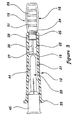
- an embodiment of a package for a blunt tip cannula and access pin made in accordance with the principles of the present invention referred to generally by the reference numeral 10, is provided for simple and rapid pre-piercing of a septum such as commonly used on a medication vial or an IV injection port (not shown), prior to insertion of a blunt tip cannula 20 therethrough to obtain or inject fluid.
- a package 10 which is designed to completely contain a sterile syringe 18 and blunt tip cannula 20, and to retain an access pin 15 protected against contamination and accidental sticking.
- the syringe 18 comprises a hollow barrel 57 and a plunger 38.
- the plunger 38 includes a plunger tip 58 and a plunger rod 40 connected to the tip 58.
- the plunger tip 58 is slidably positioned within the barrel 57 in sealing contact with the inside surface of the barrel 57.
- the rod 40 extends out of the barrel 57 and facilitates movement of the tip 58 by manipulation of the rod 40 outside the barrel 57.
- the rod 40 includes a flange 41 for convenient pushing or pulling of the rod 40 by the fingers of a user.
- the package 10 includes a sleeve 11 which is open at its distal end to allow protrusion therethrough of the sheath 12, and open at its proximal end to allow removal of the syringe/sheath assembly.
- the package 10 finally includes a cap 13 which closes the proximal opening of the sleeve 11 and which is preferably affixed to the sleeve 11 by tamper-evident means such as a heat stake 14 as is well known in the art.
- the access pin 15 is positioned in the distal end of the sheath 12 such that the handle 16 thereof protrudes from the sheath's distal end.
- the access pin 15 is also preferably held in position within the sheath 12 by means of a heat stake 17.
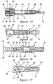
- the blunt tip cannula 20 (see figures 3 and 15) has a tip extension 44 that forms a cannula bore 43 along the longitudinal axis of cannula 20 with an attachment portion or hub 45 at the proximal end thereof adapted for securing the blunt cannula 20 to the distal end of syringe 18.
- the heat stake 14 When it is desired to remove the syringe 18 from the package 10, the heat stake 14 is broken and cap 13 is removed from the sleeve 11. The entire sheath 12, access pin 15, blunt tip cannula 20 (see Figure 3), and syringe 18 may then be withdrawn from the sleeve 11.
- the user Once removed from the sleeve 11, the user, as desired, either breaks the heat stake 17 and removes the access pin 15 from the sheath 12 to pre-pierce the septum of a vial or an IV access port, or alternatively withdraws the blunt tip cannula 20 (see Figure 3) from the proximal end of the sheath 12 for immediate use.
- the blunt tip cannula 20 and the access pin 15 with a sharp distal tip 27 are mounted in the sheath 12 for use.
- the sheath 12 is generally hollow, and is preferably bifurcated into two separate hollow sections 21 and 22 by an internal barrier 19.
- the hollow sections 21 and 22 of the sheath 12 are specifically designed to receive the blunt tip cannula 20 and access pin 15 respectively, primarily in a friction fit relationship.
- the sheath 12 may also include a flange 23 which has a diameter slightly larger than the distal opening of the sleeve 11 in order to prevent the sheath 12 from passing completely therethrough when assembled with the sleeve 11.
- the sheath 12 may include an internal rib 24 which can cooperate with an annular protruding rib 25 on the access pin 15 to cause the pin 15 to be seated in the hollow section 22 in a snap-fit manner.
- the access pin 15 preferably includes an elongate pin 26 having a sharpened, or otherwise pointed distal tip 27.
- the proximal end of the pin 26 is removably embedded in the handle 16 which includes a hub portion 28 and finger gripping portion 29.
- the finger gripping portion 29 includes an enlarged flange element 30 which abuts against the distal end of the sheath 12 when the pin 15 is properly positioned therein prior to use.
- the hub 28 is preferably sized to equal the diameter of the hollow section 22 of the sheath 12 to improve its friction fit therewith when assembled.
- the handle 16 may be formed into a relatively flat configuration and include gripping ridges 31 to improve the user's ability to securely grip the handle 16 with the fingers and the thumb.
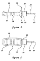
- FIGS 6-9 show alternative embodiments of the combination of the access pin 15, blunt tip cannula 20 and sheath 12 in their assembled/packaged configuration.
- Each of these alternative embodiments includes the general concept of packaging the sharp access pin 15 in such a way as to prevent accidental sticks, while at the same time allowing independent use of either the access pin 15 or the blunt tip cannula 20 while leaving the other protected by the sheath 12, without exposure to non-sterile conditions.
- each includes the general concept of positioning the access pin 15 and blunt tip cannula 20 along a single longitudinal axis which allows the user to separate one or the other from the sheath 12 in a single, safe, two-handed withdrawing motion which substantially avoids the possibility of an accidental stick or an unwanted contamination.
- the access pin 15 has been modified to include a partial sheathing member 32 which covers the blunt tip cannula 20.
- the distal tip 27 of the access pin 15 is then covered with the modified sheath 33.
- the access pin 15 has been modified in a manner similar to that described above with respect to Figure 6, except that the modified sheathing member 33 extends to cover the access pin 15 entirely and also the blunt tip cannula 20.
- the access pin 15 has been further modified to include a secondary partial sheathing member 34 which extends beyond the distal tip 27 of the pin 15.
- the modified sheath member 33 then merely covers the open end of the secondary partial sheathing member 34.
- This secondary partial sheathing member 34 can be sized to fit over the neck of a medication vial and/or the end of an IV access port, to allow the tip 27 of the pin 15 to pierce the septum.
- the sheath 12 operates again in a manner very similar to the preferred embodiment shown in Figure 3, except that the access pin 15 does not include a hub which friction fits with the internal wall of the hollow section 22, but instead includes an exterior extension 35 which fits over the exterior surface of the sheath 12.
- the embodiments of both Figures 8 and 9 include the added feature of protecting the distal tip 27 of the access pin 15 from accidental sticks even when the pin 26 is removed from the sheathing system.
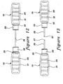
- Figure 10 shows another alternative embodiment of the present invention which includes a shearing cap 36 which is formed as part of the access pin 15.
- the sheath 12 need not have a separate internal barrier 19, since the shearing cap 36 serves the same function.
- the shearing cap 36 can be formed as part of the handle 16 such that it must be broken away from the handle 16 when the access pin 15 is removed from the sheath 12 for use. As shown in Figure 11, removal of the access pin 15 leaves the shearing cap 36 in place within the sheath 12.
- the hub 28 of the handle 16 may be modified to include a groove 37 which operates in conjunction with an internal rib 24 of the sheath 12 to hold the access pin 15 in place within the sheath 12.
- the enlarged internal rib 24 constricts the opening in the sheath 12 to a diameter sufficiently small that the hub 28 of the access pin 15 cannot be reinserted, thus operating as a non-resheathability feature as well as a tamper-evident indication.
- tamper-evident features may be added such as a shrink wrap polymeric film which can be wrapped around a portion of the sheath 12 and the access pin 15 and which is subsequently partially destroyed upon removal of the access pin 15 from the sheath 12.
- a preferred method of manufacturing access pin 15 is to form a double-length piece of pin 26 and to mold a handle 16 on each end thereof. Then, as shown in Figure 13, the double length pin 26 is. clipped at its center with an angled cut to form two finished access pins 15.
- the present invention When used to pre-pierce a septum, the present invention as shown in Figure 1 is held by the user with both hands so that the fingers of one hand are holding the handle 16 of the access pin 15 and the other hand is holding the remainder of the device.
- the access pin 15 is then pulled away from the sheath 12 and the remainder of the device is set aside.
- the user then pierces the septum of a vial or IV access port (not shown) with the access pin 15 and immediately discards the access pin 15 into an appropriate "sharps" container. Thereafter, the user removes the cap 13 and sleeve 11 from the syringe 18, and withdraws the blunt tip cannula 20 from the sheath 12.
- the blunt tip is then inserted through the pre-pierced septum into the vial or IV line and fluid is withdrawn or injected as desired.
- the user may leave the access pin 15 safely engaged within the sheath 12 and instead immediately remove the syringe 18 and blunt tip cannula 20 from the sleeve 11 and sheath 12 respectively, and insert the blunt tip cannula into the vial for removal of fluid.
- the access pin 15 or blunt tip cannula 20 remain protected at all times prior to use.
- the access pin 15 is removably embedded or otherwise inserted inside a plunger rod bore 39 formed at the proximal end of plunger 38 for securely attaching access pin 15 thereto.
- An enlarged cap 42 is provided for secure attachment, for example friction or snap fit engagement, around the proximal end of sleeve 11 in such a manner that the sterility of the access pin 15 and the rest of package 10 are maintained.
- the distal tip 27 of the access pin 15 is positioned inside the distal end of bore 43 of the blunt tip cannula 20.
- the access pin 15 is secured to the distal end of sheath 12 in a friction fit relationship thereto, while a sheath cap 46 is engaged over the flange 23 for enclosing the proximal end of access pin 15 and maintaining the sterility of the blunt tip cannula 20 and access pin 15 inside sheath 12.
- Figure 16 shows another alternative arrangement of the blunt tip cannula 20, access pin 15 and a modified protective sheath 51 with barrier 19 forming two hollow sections 21 and 22, respectively.
- barrier 19 provides a sterile seal that separates the blunt tip cannula 20 from the access pin 15, so that either the cannula 20 or the access pin 15 may be removed from package 10 without compromising the sterility of the other.
- access pin 15 is attached to a second sheath portion 56 of a secondary sheath member 47 in a friction fit engagement thereto, whereby sheath member 47 includes an enlarged rib 24 which is adapted to cooperate with the annular protruding rib 25 formed around the hub portion 28 of pin 15.
- secondary sheath member 47 further includes a first sheath portion 50 that is adapted to engage a modified sheath 51 in a friction fit engagement thereto so that sterility of the blunt tip cannula 20 is maintained.
- a flange 48 is provided around the middle portion of modified sheath 51 for engaging first sheath portion 50.
- barrier 19 may be removed and the access pin 15 spaced apart from blunt tip cannula 20.
- access pin 15 has a modified handle 52 which serves to enclose access pin 15 and for which is adapted for attachment to the proximal end of modified sheath 53.
- Sheath 53 has been modified to include an annular flange 54 which abuts the modified handle 52 when handle 52 is attached in a friction fit engagement to the proximal end of sheath 53.
- the handle 52 of the access pin 15 provides a means for encapsulating the access pin 15 and blunt tip cannula 15 inside package 10 in a sterile environment.
- a heat stake 56 may also be provided as a tamper-evident indication for package 10.
- a sterile package 9 may be utilized instead of the hardpack sterile package 10 shown in Figures 1-17.
- Figure 18 shows a softpack package 9 for a syringe 18 and blunt cannula/syringe combination 18 and 20 (see Figures 1,2, and 14) and associated access pin 15, a similar packaging arrangement could also be used for a blunt cannula 20 and associated access pin 15 without a syringe 18 (see figures 3, 6-9, 15-17).
- the access pin 15 is packaged separately from, but associated with, the blunt tip cannula 20 preattached to the syringe 18 in the same sterile package 9.
- the blunt cannula/syringe combination 18 and 20 and access pin 15 are sandwiched between a treated paper or Tyvek® backing 60 and a film 62, such as a Mylar® polyethylene laminate.
- the backing 60 and film 62 are sealed along sealing line 64 with heat or adhesive around the eriphery of the package 9 outside the articles contained therein to form a sterile barrier around the articles therein.
- the blunt cannula/syringe combination 18 and 20 may be isolated from the access pin 15 with a seal line 66 extending from one end of the package to the other at the peripheral seal line 64 between the cannula/syringe combination 18 and 20 and the access pin 15 in order to maintain the sterile conditions of both devices.
- the seal line 66 could be omitted to position the access pin 15 and cannula 20 in the same sealed sterile package.
- the syringe 18, cannula 20 and access pin 15 could be loosely enclosed in a common sterile package 9 in association with one another, or separate sterile packages 9 connected together could be employed.
- Other packaging systems may be employed to package medical devices in sterile enclosures, including, without limitation, thermoformed plastic trays with Tyvek® polyethylene laminate covering a tray adapted to contain the cannula 20, syringe 18 and access pin 15 in association with one another in accordance with the principles of the present invention.
- sheath 12 shown in figures 1-3, 6-9 and 14-18 may be collectively referred to as a "packaging device", while the different packages 9 and 10 may be referred to as a "packaging system”. Further, access pin 15 may be referred to as an "access device” and packages 9 and 10 may be referred to as a "packaging device”.
Abstract
Description
Claims (11)
- An apparatus for piercing an elastomeric membrane, comprising:an access device (15);a cannula (20) comprising a blunt tip, wherein said blunt tip is insertable into a passage through the elastomeric membrane formed by said access device (15); anda packaging device (10) for maintaining said cannula (20) and said access device (15) in association with each other prior to use, characterized in that the access device comprises a sharp solid tip (27) to penetrate the elastomeric membrane and then to be retracted intact, and thereby provide a passage through the elastomeric membrane.
- The apparatus according to claim 1, wherein said packaging device (10) includes a syringe (18) having a distal end attached to said cannula (20), and a proximal end that includes a plunger (39).
- The apparatus according to claim 1 or claim 2, wherein said packaging device (10) is a sheath (47,53), said sheath (47,53) enclosing said cannula (20).
- The apparatus according to any preceding claim wherein a cap (42) is provided to encapsulate said access device (15) in said packaging device (10) for maintaining the sterility of said access device (15).
- The apparatus according to any preceding claim wherein at least one of said access device (15) and said cannula (20) can be removed from said packaging device (10) independently of the other of said access device (15) and cannula (20).
- The apparatus of any preceding claim wherein said packaging device (10) further includes a barrier (19) that segregates said access device (15) from said cannula (20).
- The apparatus of claim 6 wherein said barrier (19) is positioned between said cannula (20) and said access device (15) when said cannula (20) and said access device (15) are assembled to said packaging device (10).
- The apparatus according to claim 7 wherein said access device (15) includes a pin (26) having a sharp distal end and said cannula (20) includes a distal end, and
wherein, assembly of said cannula (20) and said access device (15) with said packaging device (10) positions said barrier (19) between said distal end of said cannula (20) and said distal end of said pin (26) of said access device (15). - The apparatus of claim 8 wherein said cannula (20) and said access device (15) are oriented along a single longitudinal axis when assembled to said packaging device (10).
- A method of using the apparatus of any preceding claim for transferring a fluid across an elastomeric membrane, wherein said membrane is not a part of the human or animal body, said method comprising the steps of:(a) first penetrating the elastomeric membrane with an access device (15) comprising a sharp tip (27) and withdrawing the access device (15) intact, thereby providing a passage through the elastomeric membrane;(b) next inserting into the passage the blunt tip of a cannula (20) comprising a blunt tip, and substantially sealing the passage with the cannula (20); and(c) then causing the fluid to flow through the cannula (20), whereby the fluid is transferred across the elastomeric membrane; wherein the cannula (20) and the access device (15) are associated with each other by a packaging device (10) prior to use.
- A method of manufacturing an access device (15) according to any of claims 1-9, the method including the steps of:(a) forming an elongate pin member (26) which is twice as long as the final pin (26) length desired for the access device (15),(b) molding a handle (16) to each end of the elongate pin (26), and(c) cutting the pin (26) at a central position between the handles (16) to simultaneously form the sharp distal tip (27) of two identical access devices (15).
Applications Claiming Priority (3)
| Application Number | Priority Date | Filing Date | Title |
|---|---|---|---|
| US3271696P | 1996-12-16 | 1996-12-16 | |
| US32716P | 1996-12-16 | ||
| PCT/US1997/023279 WO1998026819A1 (en) | 1996-12-16 | 1997-12-16 | Blunt tip cannula with access pin |
Publications (3)
| Publication Number | Publication Date |
|---|---|
| EP1007114A1 EP1007114A1 (en) | 2000-06-14 |
| EP1007114A4 EP1007114A4 (en) | 2000-08-16 |
| EP1007114B1 true EP1007114B1 (en) | 2004-06-23 |
Family
ID=21866443
Family Applications (1)
| Application Number | Title | Priority Date | Filing Date |
|---|---|---|---|
| EP97952490A Expired - Lifetime EP1007114B1 (en) | 1996-12-16 | 1997-12-16 | Blunt tip cannula with access pin |
Country Status (14)
| Country | Link |
|---|---|
| US (2) | US6206858B1 (en) |
| EP (1) | EP1007114B1 (en) |
| JP (1) | JP4209468B2 (en) |
| CN (1) | CN1149105C (en) |
| AT (1) | ATE269722T1 (en) |
| AU (1) | AU735906B2 (en) |
| BR (1) | BR9714512A (en) |
| CA (1) | CA2274603C (en) |
| DE (1) | DE69729663T2 (en) |
| ES (1) | ES2224288T3 (en) |
| HK (1) | HK1024427A1 (en) |
| NO (1) | NO320187B1 (en) |
| NZ (1) | NZ336148A (en) |
| WO (1) | WO1998026819A1 (en) |
Families Citing this family (27)
| Publication number | Priority date | Publication date | Assignee | Title |
|---|---|---|---|---|
| US6936031B2 (en) | 2000-12-12 | 2005-08-30 | Gambro Dasco S.P.A. | Site for access to the inside of a channel, and corresponding cannula |
| US7101948B2 (en) * | 2001-12-21 | 2006-09-05 | Air Products And Chemicals, Inc. | Stabilizers to inhibit the polymerization of substituted cyclotetrasiloxane |
| US8540686B2 (en) * | 2005-03-02 | 2013-09-24 | Covidien Ag | Blunt tip vial access cannula |
| US8162894B2 (en) * | 2005-09-09 | 2012-04-24 | Cook Medical Technologies Llc | Valve opener |
| US9078781B2 (en) * | 2006-01-11 | 2015-07-14 | Medtronic, Inc. | Sterile cover for compressible stents used in percutaneous device delivery systems |
| GB2434540A (en) * | 2006-01-27 | 2007-08-01 | Owen Mumford Ltd | Lancet |
| US20070203514A1 (en) * | 2006-02-27 | 2007-08-30 | Agamatrix, Inc. | Safe Locking Lancet |
| US20080035141A1 (en) * | 2006-06-16 | 2008-02-14 | Warner W R | Aerosolized therapy kit |
| EP2139442B1 (en) * | 2007-04-23 | 2014-04-02 | Plastmed Ltd. | Method and apparatus for contamination-free transfer of a hazardous drug |
| US7981089B2 (en) * | 2008-03-31 | 2011-07-19 | Tyco Healthcare Group Lp | Vial access device |
| US20090275970A1 (en) * | 2008-04-30 | 2009-11-05 | Kyphon Sarl | Surgical access needle device and method of use |
| JP3144672U (en) * | 2008-05-19 | 2008-09-11 | 川澄化学工業株式会社 | Scab kit and medical needle |
| US8382722B2 (en) * | 2008-06-30 | 2013-02-26 | Covidien Lp | Blunt tip vial access cannula and method for manufacture |
| US9186128B2 (en) * | 2008-10-01 | 2015-11-17 | Covidien Lp | Needle biopsy device |
| DK2376147T3 (en) * | 2008-12-02 | 2018-11-19 | Fresenius Kabi Deutschland Gmbh | IMPROVED PHARMACEUTICAL CONTAINER |
| DE102009004828B4 (en) * | 2009-01-13 | 2010-12-09 | Lts Lohmann Therapie-Systeme Ag | Injector with displaceable plug part |
| JP2011136153A (en) * | 2009-10-19 | 2011-07-14 | Terumo Medical Corp | Kit with syringe assembly |
| US20110098669A1 (en) * | 2009-10-26 | 2011-04-28 | Boyes George R | Intravenous spike holder for easier penetration of sealed intravenous bag |
| KR100991708B1 (en) * | 2010-06-18 | 2010-11-03 | 송경진 | Reversible resin needle set for one time use |
| US20140290792A1 (en) * | 2010-08-13 | 2014-10-02 | Sanofi-Aventis Deutschland Gmbh | Connector for a Drug Delivery Device Reservoir |
| US9125992B2 (en) | 2011-09-16 | 2015-09-08 | Melvin A. Finke | Fluid delivery device with filtration |
| US8945087B2 (en) | 2011-09-30 | 2015-02-03 | Covidien Lp | Pre-pierced IV access port |
| JP6317767B2 (en) | 2013-02-07 | 2018-04-25 | エクアシールド メディカル リミテッド | Improvement to drug transfer sealing system |
| AU2014230834B9 (en) | 2013-03-14 | 2017-08-31 | Fresenius Kabi Deutschland Gmbh | Injectable morphine formulations |
| CA2902346A1 (en) | 2013-03-14 | 2014-09-18 | Becton Dickinson France S.A.S. | Packaging system for oxygen-sensitive drugs |
| WO2016118196A1 (en) | 2015-01-22 | 2016-07-28 | Crossroads Extremity Systems, Llc | A method for processing at least a first kit |
| US10918790B2 (en) * | 2015-12-22 | 2021-02-16 | Guangzhou Bioseal Biotech Co., Ltd. | Dual syringe with funnel feeding kit |
Family Cites Families (47)
| Publication number | Priority date | Publication date | Assignee | Title |
|---|---|---|---|---|
| US2456001A (en) | 1945-01-09 | 1948-12-14 | Jones George Emrys | Hypodermic ampoule syringe |
| US2512568A (en) | 1946-08-13 | 1950-06-20 | Jacob A Saffir | Hypodermic injection device |
| US2842126A (en) * | 1954-03-16 | 1958-07-08 | Frederick M Turnbull | Syringe assembly |
| US2855929A (en) | 1955-06-20 | 1958-10-14 | Becton Dickinson Co | Venting needle |
| US3067742A (en) | 1960-05-10 | 1962-12-11 | American Home Prod | Smallpox vaccine system |
| US3581605A (en) | 1969-10-29 | 1971-06-01 | Allied Chem | Opening device for membrane-sealed plastic bottles |
| US3650393A (en) | 1970-03-03 | 1972-03-21 | Sherwood Medical Ind Inc | Package structure |
| US3729032A (en) | 1971-12-06 | 1973-04-24 | Mpl Inc | Liquid dispenser and method and apparatus for filling same |
| US3940003A (en) | 1974-05-07 | 1976-02-24 | Pharmaco, Inc. | Safety cap for medicament vial having puncturable seal |
| US4074426A (en) | 1976-08-24 | 1978-02-21 | Brandt Michael W | Threaded blade holder |
| US4121588A (en) * | 1977-05-16 | 1978-10-24 | Becton, Dickinson And Company | Disposable hypodermic syringe and method of manufacture |
| US4197848A (en) | 1978-01-06 | 1980-04-15 | Baxter Travenol Laboratories, Inc. | Closed urinary irrigation site |
| US4153160A (en) * | 1978-01-30 | 1979-05-08 | Johannah Medical Services, Inc. | Disposable slide-step percutaneous transhepatic cholangiography procedure tray |
| US4194509A (en) * | 1978-04-11 | 1980-03-25 | C. R. Bard, Inc. | Preconnected catheter drainage system |
| US4543101A (en) | 1984-03-28 | 1985-09-24 | Adria Laboratories, Inc. | Valve device to aid in reconstituting injectable powders |
| US4595102A (en) * | 1984-12-18 | 1986-06-17 | The Kendall Company | Kit for performing a medical procedure |
| US4838877A (en) | 1985-08-06 | 1989-06-13 | Massau Bruce A | Polymeric hypodermic device |
| US4758230A (en) * | 1986-02-20 | 1988-07-19 | Becton, Dickinson And Company | Syringe barrel assembly |
| US4767416A (en) | 1986-12-01 | 1988-08-30 | Johnson & Johnson Patient Care, Inc. | Spray nozzle for syringe |
| US4840621A (en) | 1988-01-19 | 1989-06-20 | Abbott Laboratories | Piercing pin transfer device |
| US5211638A (en) | 1988-01-25 | 1993-05-18 | Baxter International Inc. | Pre-slit injection site |
| CA1335167C (en) | 1988-01-25 | 1995-04-11 | Steven C. Jepson | Pre-slit injection site and associated cannula |
| US5411499A (en) | 1988-01-25 | 1995-05-02 | Baxter International Inc. | Needleless vial access device |
| US5135489A (en) | 1988-01-25 | 1992-08-04 | Baxter International Inc. | Pre-slit injection site and tapered cannula |
| US4878903A (en) | 1988-04-15 | 1989-11-07 | Mueller Louis H | Prefilled catheter tip syringe kit |
| US5209735A (en) * | 1988-11-07 | 1993-05-11 | Lazarus Harrison M | External guide wire and enlargement means |
| JP2679834B2 (en) | 1989-01-27 | 1997-11-19 | テルモ株式会社 | Device for opening film-shaped stopper member of blood collection tube |
| US5047021A (en) | 1989-08-29 | 1991-09-10 | Utterberg David S | Male luer lock medical fitting |
| US5207699A (en) | 1989-10-30 | 1993-05-04 | Coe Frederick L | Lancet handling and disposal assembly |
| US5062836A (en) | 1990-03-14 | 1991-11-05 | The Kendall Company | Placement device for a catheter and guide wire |
| US5071413A (en) | 1990-06-13 | 1991-12-10 | Utterberg David S | Universal connector |
| US5215537A (en) | 1990-09-13 | 1993-06-01 | Lynn Lawrence A | Septum for a blunt cannula |
| US5199948A (en) | 1991-05-02 | 1993-04-06 | Mcgaw, Inc. | Needleless valve |
| US5163554A (en) * | 1992-01-10 | 1992-11-17 | Merit Medical Systems, Inc. | System and method for packaging coils of tubing |
| US5354537A (en) | 1992-04-27 | 1994-10-11 | Akzo N.V. | Piercing and sampling probe |
| US5279576A (en) | 1992-05-26 | 1994-01-18 | George Loo | Medication vial adapter |
| US5351383A (en) | 1992-07-29 | 1994-10-04 | Minnesota Mining And Manufacturing Company | Method of making an injection or sampling site |
| CZ29095A3 (en) | 1992-08-07 | 1995-07-12 | West Co | Closing device for little containers, particularly for medicaments, for providing access without need of needle |
| CA2124970A1 (en) | 1993-06-29 | 1994-12-30 | R. Hayes Helgren | Pointed adapter for blunt entry device |
| US5520657A (en) * | 1993-08-09 | 1996-05-28 | Sellers; Jackie | Method and device for vessel location cannulation utilizing a unique needle and syringe device |
| US5354275A (en) | 1993-09-13 | 1994-10-11 | Minnesota Mining And Manufacturing Company | Injection or sampling site |
| US5382241A (en) * | 1993-09-30 | 1995-01-17 | Abbott Laboratories | Adapter assembly for cannula hub syringe |
| US5403283A (en) * | 1993-10-28 | 1995-04-04 | Luther Medical Products, Inc. | Percutaneous port catheter assembly and method of use |
| US5549577A (en) | 1993-12-29 | 1996-08-27 | Ivac Corporation | Needleless connector |
| US5529189A (en) | 1995-08-02 | 1996-06-25 | Daxor Corporation | Syringe assembly for quantitative measurement of radioactive injectate and kit having same |
| US5820621A (en) * | 1997-07-29 | 1998-10-13 | Becton, Dickinson And Company | Medical fluid transfer and delivery device |
| US5807374A (en) * | 1997-08-14 | 1998-09-15 | Becton, Dickinson And Company | Syringe filling and delivery device |
-
1997
- 1997-12-16 CN CNB971807000A patent/CN1149105C/en not_active Expired - Fee Related
- 1997-12-16 EP EP97952490A patent/EP1007114B1/en not_active Expired - Lifetime
- 1997-12-16 CA CA 2274603 patent/CA2274603C/en not_active Expired - Lifetime
- 1997-12-16 AT AT97952490T patent/ATE269722T1/en not_active IP Right Cessation
- 1997-12-16 BR BR9714512A patent/BR9714512A/pt not_active IP Right Cessation
- 1997-12-16 WO PCT/US1997/023279 patent/WO1998026819A1/en active IP Right Grant
- 1997-12-16 AU AU56083/98A patent/AU735906B2/en not_active Ceased
- 1997-12-16 ES ES97952490T patent/ES2224288T3/en not_active Expired - Lifetime
- 1997-12-16 US US08/990,923 patent/US6206858B1/en not_active Expired - Lifetime
- 1997-12-16 NZ NZ336148A patent/NZ336148A/en not_active IP Right Cessation
- 1997-12-16 DE DE1997629663 patent/DE69729663T2/en not_active Expired - Lifetime
- 1997-12-16 JP JP52794198A patent/JP4209468B2/en not_active Expired - Lifetime
-
1999
- 1999-06-10 NO NO19992826A patent/NO320187B1/en not_active IP Right Cessation
-
2000
- 2000-06-20 HK HK00103698A patent/HK1024427A1/en not_active IP Right Cessation
-
2001
- 2001-01-09 US US09/757,258 patent/US6585697B2/en not_active Expired - Lifetime
Also Published As
| Publication number | Publication date |
|---|---|
| ES2224288T3 (en) | 2005-03-01 |
| WO1998026819A1 (en) | 1998-06-25 |
| CA2274603A1 (en) | 1998-06-25 |
| EP1007114A1 (en) | 2000-06-14 |
| NZ336148A (en) | 2001-12-21 |
| JP2001524846A (en) | 2001-12-04 |
| NO992826D0 (en) | 1999-06-10 |
| AU5608398A (en) | 1998-07-15 |
| US6206858B1 (en) | 2001-03-27 |
| ATE269722T1 (en) | 2004-07-15 |
| US20010004057A1 (en) | 2001-06-21 |
| CN1240365A (en) | 2000-01-05 |
| US6585697B2 (en) | 2003-07-01 |
| NO992826L (en) | 1999-08-06 |
| DE69729663T2 (en) | 2005-07-07 |
| CA2274603C (en) | 2007-05-01 |
| DE69729663D1 (en) | 2004-07-29 |
| CN1149105C (en) | 2004-05-12 |
| HK1024427A1 (en) | 2000-10-13 |
| JP4209468B2 (en) | 2009-01-14 |
| EP1007114A4 (en) | 2000-08-16 |
| NO320187B1 (en) | 2005-11-07 |
| AU735906B2 (en) | 2001-07-19 |
| BR9714512A (en) | 2000-03-21 |
Similar Documents
| Publication | Publication Date | Title |
|---|---|---|
| EP1007114B1 (en) | Blunt tip cannula with access pin | |
| EP0815888B1 (en) | Needle shield assembly having a single use cannula lock | |
| EP0589379B1 (en) | Hypodermic syringe with protective cap | |
| CA2206391C (en) | Method of making a needle shield assembly | |
| CA2221434C (en) | Syringe filling and delivery device | |
| AU717231B2 (en) | Syringe filling and delivery device | |
| EP0551465B1 (en) | Needleless vial access device | |
| AU725917B2 (en) | Syringe filling and delivery device | |
| CA2480165A1 (en) | Tamper evident overap for a container | |
| JP7270646B2 (en) | Connectors for connecting medical injection devices to containers | |
| EP0820779B1 (en) | Syringe filling and delivery device | |
| US20220362482A1 (en) | Connector for Connecting a Medical Injection Device to a Container and Assembly Comprising Said Connector and Medical Injection Device | |
| MXPA97005521A (en) | Filling and supply device of jeri | |
| AU3873501A (en) | Needle shield assembly having a single use cannula lock |
Legal Events
| Date | Code | Title | Description |
|---|---|---|---|
| PUAI | Public reference made under article 153(3) epc to a published international application that has entered the european phase |
Free format text: ORIGINAL CODE: 0009012 |
|
| 17P | Request for examination filed |
Effective date: 19990618 |
|
| AK | Designated contracting states |
Kind code of ref document: A1 Designated state(s): AT BE CH DE DK ES FI FR GB GR IE IT LI NL PT SE |
|
| A4 | Supplementary search report drawn up and despatched |
Effective date: 20000704 |
|
| AK | Designated contracting states |
Kind code of ref document: A4 Designated state(s): AT BE CH DE DK ES FI FR GB GR IE IT LI NL PT SE |
|
| RIC1 | Information provided on ipc code assigned before grant |
Free format text: 7A 61M 5/00 A, 7A 61M 39/04 B, 7A 61J 1/00 B |
|
| 17Q | First examination report despatched |
Effective date: 20021111 |
|
| GRAP | Despatch of communication of intention to grant a patent |
Free format text: ORIGINAL CODE: EPIDOSNIGR1 |
|
| GRAS | Grant fee paid |
Free format text: ORIGINAL CODE: EPIDOSNIGR3 |
|
| GRAA | (expected) grant |
Free format text: ORIGINAL CODE: 0009210 |
|
| AK | Designated contracting states |
Kind code of ref document: B1 Designated state(s): AT BE CH DE DK ES FI FR GB GR IE IT LI NL PT SE |
|
| PG25 | Lapsed in a contracting state [announced via postgrant information from national office to epo] |
Ref country code: NL Free format text: LAPSE BECAUSE OF FAILURE TO SUBMIT A TRANSLATION OF THE DESCRIPTION OR TO PAY THE FEE WITHIN THE PRESCRIBED TIME-LIMIT Effective date: 20040623 Ref country code: LI Free format text: LAPSE BECAUSE OF FAILURE TO SUBMIT A TRANSLATION OF THE DESCRIPTION OR TO PAY THE FEE WITHIN THE PRESCRIBED TIME-LIMIT Effective date: 20040623 Ref country code: FI Free format text: LAPSE BECAUSE OF FAILURE TO SUBMIT A TRANSLATION OF THE DESCRIPTION OR TO PAY THE FEE WITHIN THE PRESCRIBED TIME-LIMIT Effective date: 20040623 Ref country code: CH Free format text: LAPSE BECAUSE OF FAILURE TO SUBMIT A TRANSLATION OF THE DESCRIPTION OR TO PAY THE FEE WITHIN THE PRESCRIBED TIME-LIMIT Effective date: 20040623 Ref country code: BE Free format text: LAPSE BECAUSE OF FAILURE TO SUBMIT A TRANSLATION OF THE DESCRIPTION OR TO PAY THE FEE WITHIN THE PRESCRIBED TIME-LIMIT Effective date: 20040623 Ref country code: AT Free format text: LAPSE BECAUSE OF FAILURE TO SUBMIT A TRANSLATION OF THE DESCRIPTION OR TO PAY THE FEE WITHIN THE PRESCRIBED TIME-LIMIT Effective date: 20040623 |
|
| REG | Reference to a national code |
Ref country code: GB Ref legal event code: FG4D |
|
| REG | Reference to a national code |
Ref country code: CH Ref legal event code: EP |
|
| REG | Reference to a national code |
Ref country code: IE Ref legal event code: FG4D |
|
| REF | Corresponds to: |
Ref document number: 69729663 Country of ref document: DE Date of ref document: 20040729 Kind code of ref document: P |
|
| PG25 | Lapsed in a contracting state [announced via postgrant information from national office to epo] |
Ref country code: SE Free format text: LAPSE BECAUSE OF FAILURE TO SUBMIT A TRANSLATION OF THE DESCRIPTION OR TO PAY THE FEE WITHIN THE PRESCRIBED TIME-LIMIT Effective date: 20040923 Ref country code: GR Free format text: LAPSE BECAUSE OF FAILURE TO SUBMIT A TRANSLATION OF THE DESCRIPTION OR TO PAY THE FEE WITHIN THE PRESCRIBED TIME-LIMIT Effective date: 20040923 Ref country code: DK Free format text: LAPSE BECAUSE OF FAILURE TO SUBMIT A TRANSLATION OF THE DESCRIPTION OR TO PAY THE FEE WITHIN THE PRESCRIBED TIME-LIMIT Effective date: 20040923 |
|
| NLV1 | Nl: lapsed or annulled due to failure to fulfill the requirements of art. 29p and 29m of the patents act | ||
| REG | Reference to a national code |
Ref country code: CH Ref legal event code: PL |
|
| REG | Reference to a national code |
Ref country code: ES Ref legal event code: FG2A Ref document number: 2224288 Country of ref document: ES Kind code of ref document: T3 |
|
| ET | Fr: translation filed | ||
| PLBE | No opposition filed within time limit |
Free format text: ORIGINAL CODE: 0009261 |
|
| STAA | Information on the status of an ep patent application or granted ep patent |
Free format text: STATUS: NO OPPOSITION FILED WITHIN TIME LIMIT |
|
| 26N | No opposition filed |
Effective date: 20050324 |
|
| PG25 | Lapsed in a contracting state [announced via postgrant information from national office to epo] |
Ref country code: PT Free format text: LAPSE BECAUSE OF NON-PAYMENT OF DUE FEES Effective date: 20041123 |
|
| PGFP | Annual fee paid to national office [announced via postgrant information from national office to epo] |
Ref country code: IE Payment date: 20071224 Year of fee payment: 11 |
|
| REG | Reference to a national code |
Ref country code: IE Ref legal event code: MM4A |
|
| PG25 | Lapsed in a contracting state [announced via postgrant information from national office to epo] |
Ref country code: IE Free format text: LAPSE BECAUSE OF NON-PAYMENT OF DUE FEES Effective date: 20081216 |
|
| REG | Reference to a national code |
Ref country code: FR Ref legal event code: PLFP Year of fee payment: 19 |
|
| PGFP | Annual fee paid to national office [announced via postgrant information from national office to epo] |
Ref country code: IT Payment date: 20151120 Year of fee payment: 19 |
|
| PGFP | Annual fee paid to national office [announced via postgrant information from national office to epo] |
Ref country code: FR Payment date: 20151123 Year of fee payment: 19 Ref country code: ES Payment date: 20151204 Year of fee payment: 19 |
|
| PGFP | Annual fee paid to national office [announced via postgrant information from national office to epo] |
Ref country code: DE Payment date: 20161121 Year of fee payment: 20 Ref country code: GB Payment date: 20161128 Year of fee payment: 20 |
|
| REG | Reference to a national code |
Ref country code: FR Ref legal event code: ST Effective date: 20170831 |
|
| PG25 | Lapsed in a contracting state [announced via postgrant information from national office to epo] |
Ref country code: IT Free format text: LAPSE BECAUSE OF NON-PAYMENT OF DUE FEES Effective date: 20161216 Ref country code: FR Free format text: LAPSE BECAUSE OF NON-PAYMENT OF DUE FEES Effective date: 20170102 |
|
| REG | Reference to a national code |
Ref country code: DE Ref legal event code: R071 Ref document number: 69729663 Country of ref document: DE |
|
| REG | Reference to a national code |
Ref country code: GB Ref legal event code: PE20 Expiry date: 20171215 |
|
| PG25 | Lapsed in a contracting state [announced via postgrant information from national office to epo] |
Ref country code: GB Free format text: LAPSE BECAUSE OF EXPIRATION OF PROTECTION Effective date: 20171215 |
|
| REG | Reference to a national code |
Ref country code: ES Ref legal event code: FD2A Effective date: 20180507 |
|
| PG25 | Lapsed in a contracting state [announced via postgrant information from national office to epo] |
Ref country code: ES Free format text: LAPSE BECAUSE OF FAILURE TO SUBMIT A TRANSLATION OF THE DESCRIPTION OR TO PAY THE FEE WITHIN THE PRESCRIBED TIME-LIMIT Effective date: 20040623 |
|
| PG25 | Lapsed in a contracting state [announced via postgrant information from national office to epo] |
Ref country code: ES Free format text: LAPSE BECAUSE OF FAILURE TO SUBMIT A TRANSLATION OF THE DESCRIPTION OR TO PAY THE FEE WITHIN THE PRESCRIBED TIME-LIMIT Effective date: 20161217 |
|
| RIC2 | Information provided on ipc code assigned after grant |
Ipc: A61M 5/00 20060101AFI19981007BHEP Ipc: A61J 1/00 20060101ALI20000629BHEP Ipc: A61M 39/04 20060101ALI20000629BHEP |