EP1005290B1 - Polyaxial locking plate - Google Patents
Polyaxial locking plate Download PDFInfo
- Publication number
- EP1005290B1 EP1005290B1 EP98934463A EP98934463A EP1005290B1 EP 1005290 B1 EP1005290 B1 EP 1005290B1 EP 98934463 A EP98934463 A EP 98934463A EP 98934463 A EP98934463 A EP 98934463A EP 1005290 B1 EP1005290 B1 EP 1005290B1
- Authority
- EP
- European Patent Office
- Prior art keywords
- bushing
- plate
- bone
- locking plate
- passageway
- Prior art date
- Legal status (The legal status is an assumption and is not a legal conclusion. Google has not performed a legal analysis and makes no representation as to the accuracy of the status listed.)
- Expired - Lifetime
Links
Images


Classifications
-
- A—HUMAN NECESSITIES
- A61—MEDICAL OR VETERINARY SCIENCE; HYGIENE
- A61B—DIAGNOSIS; SURGERY; IDENTIFICATION
- A61B17/00—Surgical instruments, devices or methods, e.g. tourniquets
- A61B17/56—Surgical instruments or methods for treatment of bones or joints; Devices specially adapted therefor
- A61B17/58—Surgical instruments or methods for treatment of bones or joints; Devices specially adapted therefor for osteosynthesis, e.g. bone plates, screws, setting implements or the like
- A61B17/68—Internal fixation devices, including fasteners and spinal fixators, even if a part thereof projects from the skin
- A61B17/80—Cortical plates, i.e. bone plates; Instruments for holding or positioning cortical plates, or for compressing bones attached to cortical plates
- A61B17/8033—Cortical plates, i.e. bone plates; Instruments for holding or positioning cortical plates, or for compressing bones attached to cortical plates having indirect contact with screw heads, or having contact with screw heads maintained with the aid of additional components, e.g. nuts, wedges or head covers
- A61B17/8047—Cortical plates, i.e. bone plates; Instruments for holding or positioning cortical plates, or for compressing bones attached to cortical plates having indirect contact with screw heads, or having contact with screw heads maintained with the aid of additional components, e.g. nuts, wedges or head covers wherein the additional element surrounds the screw head in the plate hole
-
- A—HUMAN NECESSITIES
- A61—MEDICAL OR VETERINARY SCIENCE; HYGIENE
- A61B—DIAGNOSIS; SURGERY; IDENTIFICATION
- A61B17/00—Surgical instruments, devices or methods, e.g. tourniquets
- A61B17/56—Surgical instruments or methods for treatment of bones or joints; Devices specially adapted therefor
- A61B17/58—Surgical instruments or methods for treatment of bones or joints; Devices specially adapted therefor for osteosynthesis, e.g. bone plates, screws, setting implements or the like
- A61B17/68—Internal fixation devices, including fasteners and spinal fixators, even if a part thereof projects from the skin
- A61B17/70—Spinal positioners or stabilisers ; Bone stabilisers comprising fluid filler in an implant
- A61B17/7059—Cortical plates
-
- A—HUMAN NECESSITIES
- A61—MEDICAL OR VETERINARY SCIENCE; HYGIENE
- A61B—DIAGNOSIS; SURGERY; IDENTIFICATION
- A61B17/00—Surgical instruments, devices or methods, e.g. tourniquets
- A61B17/56—Surgical instruments or methods for treatment of bones or joints; Devices specially adapted therefor
- A61B17/58—Surgical instruments or methods for treatment of bones or joints; Devices specially adapted therefor for osteosynthesis, e.g. bone plates, screws, setting implements or the like
- A61B17/68—Internal fixation devices, including fasteners and spinal fixators, even if a part thereof projects from the skin
- A61B17/84—Fasteners therefor or fasteners being internal fixation devices
- A61B17/86—Pins or screws or threaded wires; nuts therefor
- A61B17/8625—Shanks, i.e. parts contacting bone tissue
- A61B17/863—Shanks, i.e. parts contacting bone tissue with thread interrupted or changing its form along shank, other than constant taper
-
- A—HUMAN NECESSITIES
- A61—MEDICAL OR VETERINARY SCIENCE; HYGIENE
- A61B—DIAGNOSIS; SURGERY; IDENTIFICATION
- A61B17/00—Surgical instruments, devices or methods, e.g. tourniquets
- A61B17/16—Bone cutting, breaking or removal means other than saws, e.g. Osteoclasts; Drills or chisels for bones; Trepans
- A61B17/17—Guides or aligning means for drills, mills, pins or wires
- A61B17/1728—Guides or aligning means for drills, mills, pins or wires for holes for bone plates or plate screws
-
- A—HUMAN NECESSITIES
- A61—MEDICAL OR VETERINARY SCIENCE; HYGIENE
- A61B—DIAGNOSIS; SURGERY; IDENTIFICATION
- A61B17/00—Surgical instruments, devices or methods, e.g. tourniquets
- A61B17/16—Bone cutting, breaking or removal means other than saws, e.g. Osteoclasts; Drills or chisels for bones; Trepans
- A61B17/17—Guides or aligning means for drills, mills, pins or wires
- A61B17/1739—Guides or aligning means for drills, mills, pins or wires specially adapted for particular parts of the body
- A61B17/1757—Guides or aligning means for drills, mills, pins or wires specially adapted for particular parts of the body for the spine
-
- A—HUMAN NECESSITIES
- A61—MEDICAL OR VETERINARY SCIENCE; HYGIENE
- A61B—DIAGNOSIS; SURGERY; IDENTIFICATION
- A61B17/00—Surgical instruments, devices or methods, e.g. tourniquets
- A61B17/56—Surgical instruments or methods for treatment of bones or joints; Devices specially adapted therefor
- A61B17/58—Surgical instruments or methods for treatment of bones or joints; Devices specially adapted therefor for osteosynthesis, e.g. bone plates, screws, setting implements or the like
- A61B17/68—Internal fixation devices, including fasteners and spinal fixators, even if a part thereof projects from the skin
- A61B17/80—Cortical plates, i.e. bone plates; Instruments for holding or positioning cortical plates, or for compressing bones attached to cortical plates
- A61B17/8052—Cortical plates, i.e. bone plates; Instruments for holding or positioning cortical plates, or for compressing bones attached to cortical plates immobilised relative to screws by interlocking form of the heads and plate holes, e.g. conical or threaded
- A61B17/8057—Cortical plates, i.e. bone plates; Instruments for holding or positioning cortical plates, or for compressing bones attached to cortical plates immobilised relative to screws by interlocking form of the heads and plate holes, e.g. conical or threaded the interlocking form comprising a thread
Definitions
- the present invention relates to a bone locking plate, more particularly the present invention relates to a bone locking plate that includes an adjustable attachment component. Most particularly, the present invention relates to a bone locking plate that includes an attachment component whose angle relative to the locking plate may be manipulated during surgery so that it extends into the bone in a desirable orientation.
- the spinal column includes over twenty bones that are coupled together. These bones are capable of twisting and curving in a variety of directions relative to one another. Traumas and developmental irregularities can result, however, in spinal pathologies for which permanent immobilization of multiple vertebrae in the spinal column is required. It is known to place a bone screw through a bone plate along an axis that has been selected by the manufacturer of the plate, for example as disclosed in US-5364399 and US-4484570 . Since bone screws are known to pull out of the bone over time, these conventional bone plates have main bone-plate screws that lock down using additional loose components that either cover adjacent screws or are threaded into the head/shaft of the bone screw to prevent the screws from backing out of the bone. Often, however, the most desirable screw angle for fixing the bone screw is difficult if not impossible to determine prior to surgery.
- US-5053036 discloses a bone plate in which a conical insert is provided in a hole for a fixation screw, in which the insert can be expanded when the fixation screw is inserted into it so that it becomes locked in the hole.
- the present invention provides locking plate apparatus for engagement with a bone, the apparatus according to claim 1.
- the apparatus of the invention can be used in a method for coupling two bone portions together, which includes the steps of providing a locking apparatus that includes a plate having a body portion and an internal wall defining at least two plate holes through the body portion, at least two expandable bushings press fit into the respective plate holes each having a radially exterior surface and an opposite interior surface and a first end and an opposite second end defining a passageway between them and at least two attachment components being sized for extension into the passageway, each attachment component including opposite leading and trailing portions.
- the method includes the steps of positioning the body portion upon the bone portions so that the plate holes in the plate are situated over bone, rotating at least one of the bushings within the plate hole about a plurality of axes until the first and second ends of the bushing are aligned along an axis that extends through a pre-determined portion of the bone. Further, the method includes the steps of inserting the leading portion of one attachment component through each passageway and driving the trailing portion of each attachment component through the respective passageway until the leading portion is positioned in the bone and the exterior surface of the bushing is pressed against the internal wall of the plate to form a friction lock between them.
- Fig. 1 illustrates a locking plate apparatus 10 in accordance with the present invention as apparatus 10 appears to a surgeon during attachment of apparatus 10 to vertebrae 11.
- Locking plate apparatus 10 includes a locking plate 12 and corresponding semi-split donut shaped bushings 16 press-fit into locking plate 12 to form a plate subassembly 17, and thread-through bone screws 18.
- Locking plate apparatus 10 beneficially enables a surgeon, without a large number of loose pieces, to achieve infinite angulation (3-D) within a specified conical volume while rigidly locking bone screws 18 to rigid locking plate 12.
- Non-limiting examples of applications of locking plate apparatus 10 include the following: long bone fracture fixation/stabilization, small bone stabilization, lumbar spine as well as thoracic stabilization/fusion and burst fracture fixation, cervical spine compression/fixation, and skull fracture/reconstruction plating.
- Locking plate 12 includes a rigid body portion 20 having a proximal surface 22 resting upon vertebrae 11 and an opposite distal surface 24.
- body portion 20 includes two walls 23 that define two graft holes 25 and six internal walls 26 that define six spherically shaped plate holes 14. Walls 23 may form graft holes 25 with a cylindrical, spherical shape, or any number of shapes.
- each plate hole 14 is sized to receive bushing 16 therein to form subassembly 17. It is understood that plate holes 14 can also be elliptical-shaped, teardrop-shaped, or be defined by any number of rounded shapes in accordance with the present invention. Plate holes 14 extend through body portion 20 between proximal and distal surfaces 22, 24.
- Locking plate 12 may include one, two, four, or five sets of two plate holes, or may be used in conjunction with any number of holes in a variety of plates. Although locking plate 12 is illustrated and described, it is understood that locking plates may be formed in any number of shapes and sizes for varying applications. Locking plate 12 is constructed of a titanium alloy, although it is understood that locking plate 12 may be constructed of titanium, stainless steel, or any number of a wide variety of materials possessing the mechanical properties suitable for coupling bones together.
- each donut-shaped bushing 16 is sized so that it is press fit into plate hole 14 of locking plate 12 to form subassembly 17.
- Bushing 16 will withstand pressure that is applied thereto without slipping out from plate holes 14 in locking plate 12. It is understood that while one bushing 16 will be described hereafter, the description applies to all bushings 16.
- Bushing 16 is constructed of a titanium alloy, although it is understood that bushing may be constructed of titanium, stainless steel, or any number of a wide variety of materials possessing the mechanical properties suitable for frictionally engaging locking plate 12.
- bushing 16 includes a first end 32 configured to lie adjacent proximal surface 22 and an opposite second end 34 positioned to lie adjacent distal surface 24 of locking plate 12.
- bushing 16 includes a spherical-shaped radially exterior surface 28 extending between first and second ends 32, 34 and an opposite radially interior surface 30. While bushing 16 is illustrated with a spherically shaped and smooth exterior surface 28, it is understood that exterior surface 28 may be formed in a variety of rounded shapes and sizes to cooperate with internal wall 26 of locking plate 12.
- radially interior surface 30 defines a passageway 36 that has an initial predetermined diameter 68 at second end 34 and that extends between first and second ends 32, 34 of bushing 16.
- bushing 16 is formed to include a radial slot 46 that extends between exterior surface 28 and interior surface 30.
- slot 46 has an initial pre-determined dimension 58. While slot 46 is illustrated and described, it is understood that bushing 16 may include multiple slots, cut-outs or otherwise be constructed to permit expansion of exterior surface 28. Radial expansion of bushing 16 expands slot 46 and presses exterior surface 28 against internal wall 26 for locking engagement between bushing 16 and locking plate 12.
- Radially interior surface 30 of bushing 16 also includes threads 38 that extend radially inwardly into passageway 36 and define a diameter 72 adjacent to second end 34 therebetween.
- threads 38 taper from second end 34 toward first end 32, as shown by lines 39.
- Tapered threads 38 converge at an angle of about five degrees to about twenty degrees, more preferably about five degrees to about twelve degrees, and most preferably about six degrees.
- threads 38 have a tread pitch that is a multiple lead, with leads that start about 120°.
- the tapered pitch is a triple lead, although it is understood that the thread pitch, number of leads, and spacing may vary in accordance with the present invention.
- exterior surface 28 of bushing 16 is positioned to lie within plate hole 14 of body portion 20 and engages internal wall 26.
- exterior surface 28 is sized to permit angled rotation of bushing 16 within plate hole 14 along a plurality of axes, as shown for example by lines 40, 42, 44. See Fig. 5 .
- bushing 16 may be rotated within plate hole 14 along a plurality of axes so long as passageway 36 extends unobstructed between proximal and distal surfaces 22, 24 of locking plate 12 to permit extension of bone screw 18 therethrough.
- bushing 16 movably rides in plate hole 14 to form subassembly 17.
- locking plate 12 has six plate holes 14 and six bushings 16 ride in six bone holes 14 and rotate independently of one another.
- subassembly 17 couples bone screws 18 therein without additional loose attachment components, providing surgeons an easy to handle locking plate apparatus 10.
- Bone screw 18 is formed to engage bushing 16 and to fix the relative positioning of bushing 16 in plate hole 14. It is understood that while one bone screw 18 will be described hereafter, the description applies to all bone screws 18. Bone screw 18 is sized for extension through passageway 36 of bushing 16 and for pressing exterior surface 28 against internal wall 26 of locking plate 12 to form a friction lock between bushing 16 and locking plate 12. As shown in Fig. 5 , bone screw 18 includes a leading portion 48 sized for extension through passageway 36 and into bone 11, an opposite trailing portion 50, and a middle portion 52 positioned to lie between leading and trailing portions 48, 50. Illustratively, leading portion 48 includes a plurality of sharp cutting edges 49 for self-tapping and reliefs 51 spaced apart from one another.
- Bone screw 18 also includes an outer surface 54 and threads 56 extending about outer surface 54. Threads 56 have a thread pitch that is single lead 60 between leading and trailing portions 48, 50. Bone screw 18 also has thread pitch that is multiple lead 62 adjacent trailing portion 50. Simply, bone screw 18 includes a single lead 60 from tip to top with additional leads 62 being started within middle 52 toward trailing portion 50. Bone screw 18 is constructed of titanium alloy, although it is understood that bone screw 18 may be constructed of titanium, stainless steel, or any number of a wide variety of materials possessing the mechanical properties suitable for attachment with bone.
- single lead 60 adjacent to leading portion 48 engages threads 38 of bushing 16 prior to engaging bone 11.
- Threads 56 of single lead 60 have a diameter, as shown by arrow 128, that is greater than diameter 72 of threads 38.
- threads 38 in bushing 16 will engage and guide single lead 60 during insertion of bone screw 18 into bone 11.
- trailing portion 50 of bone screw 18 has a tapered portion 70 that diverges, as shown by lines 71, away from leading portion 48.
- tapered portion diverges at an angle of about six degrees from leading portion 48.
- Tapered portion 70 is sized to engage interior surface 30 of bushing 16 and expand diameter 68 of passageway 36 so that dimension 58 of slot 46 increases and exterior surface 28 is pressed against internal wall 26 to form the friction lock between bushing 16 and locking plate 12.
- multiple lead 62 is positioned to lie on tapered portion 70. Thread pitch of multiple lead 62 has leads that start about 120°. It is understood that leads between leading and trailing portions 48, 50 may vary in pitch and number in accordance with the present invention.
- bone screw 18 is illustrated and described, it is understood that locking plate 12 may be coupled to bone 11 with a variety of attachment components.
- leading portion 48 of bone screw 18 may instead be a plug or a porous coated spike, so long as leading portion 48 attaches to bone 11 and trailing portion 50 expands bushing 16 frictionally to lock bushing 16 in position in plate hole 14.
- locking plate apparatus 110 that include locking plate 12, bushings 16, and drop-in bone screws 118. See Fig. 6 .
- locking plate apparatus 110 is similar to locking plate apparatus 10 illustrated in Figs. 1-5 , like reference numerals will be used to denote like components.
- bone screw 118 has a single lead 122 adjacent leading portion 48.
- Bone screw 118 also has a tapered multiple lead 124 adjacent to trailing portion 50.
- Multiple lead 124 has a diameter sized to spread bushing 16 to provide a friction lock with locking plate 12.
- single lead 122 of bone screw 118 has a diameter as shown by arrow 166 that is less than diameter 72 of threads 38 in bushing 16. Therefore, leading portion 48 of bone screw 118 is sized to slide through passageway 36 spaced apart from threads 38 of bushing 16.
- Multiple lead 124 is positioned on tapered portion 70 of bone screw 118 and engages threads 38 on bushing 16. Referring to Fig. 6 , threads 38 of bushing 16 are configured to receive threads 123 of multiple lead 124 thereon and to guide insertion of tapered portion 70 into passageway 36.
- a graft screw 218 is illustrated in Fig. 7 and is suitable for use with subassembly 17 in accordance with the present invention.
- Graft screw 218 is sized for extension through graft holes 25 and to stabilize the graft prior to fusion.
- Graft screw 218 includes a leading portion 220 and an opposite headed trailing portion 222.
- Graft screw 218 further includes an exterior wall 224 extending between leading and trailing portions 220, 222. Exterior wall 224 diverges from leading portion 220 toward trailing portion 222 at an angle of about six degrees.
- threads 226 extend about exterior wall 224.
- exterior wall 224 becomes tighter and tighter against wall 23 until graft screw 218 snaps into place. While graft screw 218 is illustrated and described, it is understood that graft screws having a variety of shapes and sizes and other suitable attachment mechanisms may be used in accordance with the present invention to stabilize the graft.
- drill guide 130 includes a handle portion 132 and an elongated guide portion 134 defining a plate hole 136 having axis 137 extending therethrough.
- Guide portion 134 includes an upper end 140 sized for insertion of a drill bit (not shown) therethrough and a lower end 142 having a stop portion 144 thereon. Stop portion 144 is sized to limit extension of guide portion 134 through plate hole 14 of locking plate 12.
- lower end 142 includes threads 146 that are sized to engage threads 38 on bushing 16. Therefore, to position drill guide 130 in passageway 36, lower end 142 is rotated relative to bushing 16 to couple threads 146 to threads 38 on bushing 16. While drill guide 130 is illustrated and described, it is understood that a drill tube or a wide variety of drill bit positioning mechanisms may be used to position bushing 16 in locking plate 12.
- drill guide 130 engages bushing 16
- the surgeon is free to rotate bushing 16 in plate hole 14 relative to vertebrae 11 along a plurality of axes 40, 42, 44 by moving handle portion 132 relative to locking plate 12.
- a desirable position of bushing 16 relative to locking plate 12 is selected by angling bushing 16 so that axis 137 of guide portion 132 and therefore passageway 36 of bushing 16 extends through a desirable segment of bone 11.
- the surgeon uses a drill (not shown) to drill a pilot hole (not shown) into vertebrae 11 that is sized to receive leading portion 48 of bone screw 18. Drill guide 130 is then removed from passageway 36 of bushing 16.
- Leading portion 48 of bone screw 18 is then inserted into passageway 36 of expandable bushing 16.
- threads 38 on bushing 16 receive threads 56 on leading portion 48 and guide leading portion 48 through passageway 36.
- the surgeon then rotates trailing portion 50 as shown by arrow 51 until leading portion 48 exits first end 32 of bushing 16 and extends into pilot hole (not shown).
- tapered portion 70 adjacent trailing portion 50 engages threads 38 on bushing 16.
- Continued rotation 51 in bushing 16 causes threads 38 on bushing 16 to receive threads 62 on tapered portion 70 and guide tapered portion 70 into passageway 36.
- tapered portion 70 expands diameter 68 of passageway 36 and presses exterior surface 28 of bushing 16 into a frictional locking engagement with internal wall 26 of locking plate 12. It is understood, that while drill guide 130 is illustrated and described, leading portion 48 of bone screw 18 may be formed to extend into bone 11 without a pilot hole.
- leading portion 48 of bone screw 118 is inserted into passageway 36 of bushing 16. During insertion, leading portion 48 slides through passageway 36 so that threads 38 of bushing 16 are spaced apart from threads 56 of leading portion 48. Once leading portion 48 has "dropped into” pilot hole, tapered portion 70 adjacent to trailing portion 50 is rotated. Threads 38 on bushing 16 receive threads 123 on tapered portion 70 and guide tapered portion 70 into passageway 36. The surgeon continues to rotate bone screw 118 within bushing 16 until tapered portion 70 expands diameter 68 of passageway 36 and therefore presses spherical exterior surface 28 of bushing 16 into a frictional locking engagement with spherical internal wall 26 of locking plate 12.
Abstract
Description
- The present invention relates to a bone locking plate, more particularly the present invention relates to a bone locking plate that includes an adjustable attachment component. Most particularly, the present invention relates to a bone locking plate that includes an attachment component whose angle relative to the locking plate may be manipulated during surgery so that it extends into the bone in a desirable orientation.
- The spinal column includes over twenty bones that are coupled together. These bones are capable of twisting and curving in a variety of directions relative to one another. Traumas and developmental irregularities can result, however, in spinal pathologies for which permanent immobilization of multiple vertebrae in the spinal column is required. It is known to place a bone screw through a bone plate along an axis that has been selected by the manufacturer of the plate, for example as disclosed in
US-5364399 andUS-4484570 . Since bone screws are known to pull out of the bone over time, these conventional bone plates have main bone-plate screws that lock down using additional loose components that either cover adjacent screws or are threaded into the head/shaft of the bone screw to prevent the screws from backing out of the bone. Often, however, the most desirable screw angle for fixing the bone screw is difficult if not impossible to determine prior to surgery. - Therefore, conventional devices have been provided that allow the user to angulate a bone screw prior to placement, for example as disclosed in
US-5607426 . These conventional systems, however, also include multiple loose components that must be assembled to couple the bone screw head and plate hole bearing surface. These multi-component traditional plate assemblies can be cumbersome and tedious to manipulate during surgery to achieve the most desirable angle for directing the bone screw into the patient. -
US-5053036 (The preamble of claim 1 is based on this document.) discloses a bone plate in which a conical insert is provided in a hole for a fixation screw, in which the insert can be expanded when the fixation screw is inserted into it so that it becomes locked in the hole. - The present invention provides locking plate apparatus for engagement with a bone, the apparatus according to claim 1.
- The apparatus of the invention can be used in a method for coupling two bone portions together, which includes the steps of providing a locking apparatus that includes a plate having a body portion and an internal wall defining at least two plate holes through the body portion, at least two expandable bushings press fit into the respective plate holes each having a radially exterior surface and an opposite interior surface and a first end and an opposite second end defining a passageway between them and at least two attachment components being sized for extension into the passageway, each attachment component including opposite leading and trailing portions. In addition, the method includes the steps of positioning the body portion upon the bone portions so that the plate holes in the plate are situated over bone, rotating at least one of the bushings within the plate hole about a plurality of axes until the first and second ends of the bushing are aligned along an axis that extends through a pre-determined portion of the bone. Further, the method includes the steps of inserting the leading portion of one attachment component through each passageway and driving the trailing portion of each attachment component through the respective passageway until the leading portion is positioned in the bone and the exterior surface of the bushing is pressed against the internal wall of the plate to form a friction lock between them.
-
-
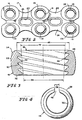
Fig. 1 is a perspective view of a locking apparatus in accordance with the present invention coupled to vertebrae and showing the locking apparatus including a locking plate having six plate holes and corresponding slotted bushings having a threaded passageway therethrough and thread-through bone screws; -
Fig. 2 is a top view of the locking apparatus ofFig. 1 prior to placement of the bone screws therethrough and showing six bushings press-fit into the six plate holes to form a locking plate/bushing subassembly; -
Fig. 3 is a cross sectional view taken along lines 3-3 ofFig. 1 showing the bushing having a cylindrically-shaped exterior surface and an interior surface having threads extending into the passageway; -
Fig. 4 is a top view of the bushing ofFig. 3 showing the bushing including a slot therethrough and showing the slot having a pre-determined dimension prior to extension of the bone screw through the passageway; -
Fig. 5 is a cross section taken along lines 5-5 ofFig. 1 during attachment of the locking apparatus on the vertebrae, showing each thread-through bone screw including a single lead and multiple lead that tapers in a radially outward direction from the single lead and showing the multiple lead of a first bone screw frictionally coupling the bushing to the locking plate and showing the single lead of a second bone screw engaging the threads positioned within the passageway of the bushing; -
Fig. 6 is a view similar toFig. 5 of an alternative embodiment of the present invention showing a locking apparatus including a locking plate, threaded bushings, and drop-in bone screws that each include a single lead sized for extension through the passageway spaced-apart from the threads of the bushing and a triple lead that presses the bushing against the locking plate frictionally to couple the bushing and the locking plate together; -
Fig. 7 is a side view of a graft screw, suitable for extending through graft holes in the locking plate; and -
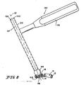
Fig. 8 is a cross-sectional view of the locking plate/bushing subassembly showing a drill guide extending into the passageway of one of the bushings to manipulate the positioning of the bushing in the plate hole relative to the bone. -
Fig. 1 illustrates alocking plate apparatus 10 in accordance with the present invention asapparatus 10 appears to a surgeon during attachment ofapparatus 10 to vertebrae 11.Locking plate apparatus 10 includes alocking plate 12 and corresponding semi-split donut shapedbushings 16 press-fit intolocking plate 12 to form aplate subassembly 17, and thread-throughbone screws 18.Locking plate apparatus 10 beneficially enables a surgeon, without a large number of loose pieces, to achieve infinite angulation (3-D) within a specified conical volume while rigidly lockingbone screws 18 torigid locking plate 12. Non-limiting examples of applications oflocking plate apparatus 10 include the following: long bone fracture fixation/stabilization, small bone stabilization, lumbar spine as well as thoracic stabilization/fusion and burst fracture fixation, cervical spine compression/fixation, and skull fracture/reconstruction plating. -
Locking plate 12 includes arigid body portion 20 having aproximal surface 22 resting upon vertebrae 11 and an oppositedistal surface 24. In addition,body portion 20 includes twowalls 23 that define twograft holes 25 and sixinternal walls 26 that define six sphericallyshaped plate holes 14.Walls 23 may formgraft holes 25 with a cylindrical, spherical shape, or any number of shapes. As shown inFig. 2 , eachplate hole 14 is sized to receive bushing 16 therein to form subassembly 17. It is understood thatplate holes 14 can also be elliptical-shaped, teardrop-shaped, or be defined by any number of rounded shapes in accordance with the present invention.Plate holes 14 extend throughbody portion 20 between proximal anddistal surfaces Figs. 1 and2 , three sets of twoplate holes 14 are positioned to lie in a side-by-side relationship throughbody portion 20.Locking plate 12, however, may include one, two, four, or five sets of two plate holes, or may be used in conjunction with any number of holes in a variety of plates. Althoughlocking plate 12 is illustrated and described, it is understood that locking plates may be formed in any number of shapes and sizes for varying applications.Locking plate 12 is constructed of a titanium alloy, although it is understood thatlocking plate 12 may be constructed of titanium, stainless steel, or any number of a wide variety of materials possessing the mechanical properties suitable for coupling bones together. - As shown in
Fig. 2 , each donut-shaped bushing 16 is sized so that it is press fit intoplate hole 14 oflocking plate 12 to form subassembly 17.Bushing 16 will withstand pressure that is applied thereto without slipping out fromplate holes 14 inlocking plate 12. It is understood that while one bushing 16 will be described hereafter, the description applies to allbushings 16.Bushing 16 is constructed of a titanium alloy, although it is understood that bushing may be constructed of titanium, stainless steel, or any number of a wide variety of materials possessing the mechanical properties suitable for frictionally engaginglocking plate 12. - As shown in
Figs. 3 and5 ,bushing 16 includes afirst end 32 configured to lie adjacentproximal surface 22 and an oppositesecond end 34 positioned to lie adjacentdistal surface 24 oflocking plate 12. In addition,bushing 16 includes a spherical-shaped radiallyexterior surface 28 extending between first andsecond ends interior surface 30. Whilebushing 16 is illustrated with a spherically shaped and smoothexterior surface 28, it is understood thatexterior surface 28 may be formed in a variety of rounded shapes and sizes to cooperate withinternal wall 26 oflocking plate 12. - As shown in
Fig. 3 , radiallyinterior surface 30 defines apassageway 36 that has an initialpredetermined diameter 68 atsecond end 34 and that extends between first andsecond ends bushing 16. Moreover, as shown inFigs. 2 and 4 , bushing 16 is formed to include aradial slot 46 that extends betweenexterior surface 28 andinterior surface 30. As shown inFig. 4 ,slot 46 has an initial pre-determineddimension 58. Whileslot 46 is illustrated and described, it is understood that bushing 16 may include multiple slots, cut-outs or otherwise be constructed to permit expansion ofexterior surface 28. Radial expansion of bushing 16 expandsslot 46 and pressesexterior surface 28 againstinternal wall 26 for locking engagement between bushing 16 andlocking plate 12. - Radially
interior surface 30 ofbushing 16 also includesthreads 38 that extend radially inwardly intopassageway 36 and define adiameter 72 adjacent tosecond end 34 therebetween. As shown inFig. 3 ,threads 38 taper fromsecond end 34 towardfirst end 32, as shown bylines 39. Taperedthreads 38 converge at an angle of about five degrees to about twenty degrees, more preferably about five degrees to about twelve degrees, and most preferably about six degrees. In addition,threads 38 have a tread pitch that is a multiple lead, with leads that start about 120°. Illustratively, the tapered pitch is a triple lead, although it is understood that the thread pitch, number of leads, and spacing may vary in accordance with the present invention. - Referring now to
Fig. 2 ,exterior surface 28 ofbushing 16 is positioned to lie withinplate hole 14 ofbody portion 20 and engagesinternal wall 26. In addition,exterior surface 28 is sized to permit angled rotation of bushing 16 withinplate hole 14 along a plurality of axes, as shown for example bylines Fig. 5 . Illustratively, bushing 16 may be rotated withinplate hole 14 along a plurality of axes so long aspassageway 36 extends unobstructed between proximal anddistal surfaces locking plate 12 to permit extension ofbone screw 18 therethrough. Thus, bushing 16 movably rides inplate hole 14 to form subassembly 17. As shown inFig. 2 ,locking plate 12 has sixplate holes 14 and sixbushings 16 ride in sixbone holes 14 and rotate independently of one another. Beneficially, subassembly 17couples bone screws 18 therein without additional loose attachment components, providing surgeons an easy to handlelocking plate apparatus 10. -
Bone screw 18 is formed to engagebushing 16 and to fix the relative positioning ofbushing 16 inplate hole 14. It is understood that while onebone screw 18 will be described hereafter, the description applies to all bone screws 18.Bone screw 18 is sized for extension throughpassageway 36 ofbushing 16 and for pressingexterior surface 28 againstinternal wall 26 of lockingplate 12 to form a friction lock betweenbushing 16 and lockingplate 12. As shown inFig. 5 ,bone screw 18 includes a leadingportion 48 sized for extension throughpassageway 36 and into bone 11, an opposite trailingportion 50, and amiddle portion 52 positioned to lie between leading and trailingportions portion 48 includes a plurality ofsharp cutting edges 49 for self-tapping andreliefs 51 spaced apart from one another. -
Bone screw 18 also includes anouter surface 54 andthreads 56 extending aboutouter surface 54.Threads 56 have a thread pitch that issingle lead 60 between leading and trailingportions Bone screw 18 also has thread pitch that ismultiple lead 62 adjacent trailingportion 50. Simply,bone screw 18 includes asingle lead 60 from tip to top withadditional leads 62 being started within middle 52 toward trailingportion 50.Bone screw 18 is constructed of titanium alloy, although it is understood thatbone screw 18 may be constructed of titanium, stainless steel, or any number of a wide variety of materials possessing the mechanical properties suitable for attachment with bone. - As shown in
Fig. 5 ,single lead 60 adjacent to leadingportion 48 engagesthreads 38 ofbushing 16 prior to engaging bone 11.Threads 56 ofsingle lead 60 have a diameter, as shown byarrow 128, that is greater thandiameter 72 ofthreads 38. Thus,threads 38 inbushing 16 will engage and guidesingle lead 60 during insertion ofbone screw 18 into bone 11. As shown inFig. 5 , trailingportion 50 ofbone screw 18 has a taperedportion 70 that diverges, as shown bylines 71, away from leadingportion 48. Illustratively, tapered portion diverges at an angle of about six degrees from leadingportion 48.Tapered portion 70 is sized to engageinterior surface 30 ofbushing 16 and expanddiameter 68 ofpassageway 36 so thatdimension 58 ofslot 46 increases andexterior surface 28 is pressed againstinternal wall 26 to form the friction lock betweenbushing 16 and lockingplate 12. Illustratively,multiple lead 62 is positioned to lie on taperedportion 70. Thread pitch ofmultiple lead 62 has leads that start about 120°. It is understood that leads between leading and trailingportions bone screw 18 is illustrated and described, it is understood that lockingplate 12 may be coupled to bone 11 with a variety of attachment components. For example, leadingportion 48 ofbone screw 18 may instead be a plug or a porous coated spike, so long as leadingportion 48 attaches to bone 11 and trailingportion 50 expandsbushing 16 frictionally to lockbushing 16 in position inplate hole 14. - In an alternative embodiment of the present invention, locking plate apparatus 110 is provided that include locking
plate 12,bushings 16, and drop-in bone screws 118. SeeFig. 6 . To the extent that locking plate apparatus 110 is similar to lockingplate apparatus 10 illustrated inFigs. 1-5 , like reference numerals will be used to denote like components. Referring toFig. 6 ,bone screw 118 has asingle lead 122 adjacent leadingportion 48.Bone screw 118 also has a taperedmultiple lead 124 adjacent to trailingportion 50.Multiple lead 124 has a diameter sized to spreadbushing 16 to provide a friction lock with lockingplate 12. - As shown in
Fig. 6 ,single lead 122 ofbone screw 118 has a diameter as shown byarrow 166 that is less thandiameter 72 ofthreads 38 inbushing 16. Therefore, leadingportion 48 ofbone screw 118 is sized to slide throughpassageway 36 spaced apart fromthreads 38 ofbushing 16.Multiple lead 124, however, is positioned on taperedportion 70 ofbone screw 118 and engagesthreads 38 onbushing 16. Referring toFig. 6 ,threads 38 ofbushing 16 are configured to receivethreads 123 ofmultiple lead 124 thereon and to guide insertion of taperedportion 70 intopassageway 36. - A
graft screw 218 is illustrated inFig. 7 and is suitable for use withsubassembly 17 in accordance with the present invention.Graft screw 218 is sized for extension through graft holes 25 and to stabilize the graft prior to fusion.Graft screw 218 includes a leadingportion 220 and an opposite headed trailingportion 222.Graft screw 218 further includes anexterior wall 224 extending between leading and trailingportions Exterior wall 224 diverges from leadingportion 220 toward trailingportion 222 at an angle of about six degrees. Moreover,threads 226 extend aboutexterior wall 224. Asgraft screw 218 extends into bone 11,exterior wall 224 becomes tighter and tighter againstwall 23 untilgraft screw 218 snaps into place. Whilegraft screw 218 is illustrated and described, it is understood that graft screws having a variety of shapes and sizes and other suitable attachment mechanisms may be used in accordance with the present invention to stabilize the graft. - To couple locking
plate 12 to bone 11, the surgeonfirst positions subassembly 17 on bone 11 and selects a desirable angle in which to insertbone screw 18 into bone 11. Adrill guide 130 is then inserted intopassageway 36 ofbushing 16 situated withinplate hole 14 of lockingplate 12. As shown inFig. 8 ,drill guide 130 includes ahandle portion 132 and anelongated guide portion 134 defining aplate hole 136 havingaxis 137 extending therethrough.Guide portion 134 includes anupper end 140 sized for insertion of a drill bit (not shown) therethrough and alower end 142 having astop portion 144 thereon.Stop portion 144 is sized to limit extension ofguide portion 134 throughplate hole 14 of lockingplate 12. In addition,lower end 142 includesthreads 146 that are sized to engagethreads 38 onbushing 16. Therefore, to positiondrill guide 130 inpassageway 36,lower end 142 is rotated relative tobushing 16 to couplethreads 146 tothreads 38 onbushing 16. Whiledrill guide 130 is illustrated and described, it is understood that a drill tube or a wide variety of drill bit positioning mechanisms may be used to positionbushing 16 in lockingplate 12. - Once
drill guide 130 engagesbushing 16, the surgeon is free to rotatebushing 16 inplate hole 14 relative to vertebrae 11 along a plurality ofaxes handle portion 132 relative to lockingplate 12. A desirable position ofbushing 16 relative to lockingplate 12 is selected by anglingbushing 16 so thataxis 137 ofguide portion 132 and thereforepassageway 36 ofbushing 16 extends through a desirable segment of bone 11. Once a desirable position is selected, the surgeon uses a drill (not shown) to drill a pilot hole (not shown) into vertebrae 11 that is sized to receive leadingportion 48 ofbone screw 18.Drill guide 130 is then removed frompassageway 36 ofbushing 16. - Leading
portion 48 ofbone screw 18 is then inserted intopassageway 36 ofexpandable bushing 16. Uponbone screw 18 enteringpassageway 36,threads 38 onbushing 16 receivethreads 56 on leadingportion 48 and guide leadingportion 48 throughpassageway 36. The surgeon then rotates trailingportion 50 as shown byarrow 51 until leadingportion 48 exits first end 32 ofbushing 16 and extends into pilot hole (not shown). Once leadingportion 48 has exitedbushing 16, taperedportion 70 adjacent trailingportion 50 engagesthreads 38 onbushing 16. Continuedrotation 51 inbushing 16 causesthreads 38 onbushing 16 to receivethreads 62 on taperedportion 70 and guide taperedportion 70 intopassageway 36. Thus, taperedportion 70 expandsdiameter 68 ofpassageway 36 and pressesexterior surface 28 ofbushing 16 into a frictional locking engagement withinternal wall 26 of lockingplate 12. It is understood, that whiledrill guide 130 is illustrated and described, leadingportion 48 ofbone screw 18 may be formed to extend into bone 11 without a pilot hole. - In another embodiment of the present invention, leading
portion 48 ofbone screw 118 is inserted intopassageway 36 ofbushing 16. During insertion, leadingportion 48 slides throughpassageway 36 so thatthreads 38 ofbushing 16 are spaced apart fromthreads 56 of leadingportion 48. Once leadingportion 48 has "dropped into" pilot hole, taperedportion 70 adjacent to trailingportion 50 is rotated.Threads 38 onbushing 16 receivethreads 123 on taperedportion 70 and guide taperedportion 70 intopassageway 36. The surgeon continues to rotatebone screw 118 withinbushing 16 until taperedportion 70 expandsdiameter 68 ofpassageway 36 and therefore presses sphericalexterior surface 28 ofbushing 16 into a frictional locking engagement with sphericalinternal wall 26 of lockingplate 12.
Claims (9)
- Locking plate apparatus (10) for engagement with a bone, the apparatus comprising:a plate (12) including a body portion (20) and an internal wall (26) defining a plate hole (14) through the body portion,an attachment component (18) which has a leading portion (48) sized for extension through the plate hole into the bone and an opposite trailing portion (50) which is fixedly connected to the leading portion and is tapered, anda bushing (16) which has a radially exterior surface (28) and an opposite radially interior surface (30) defining a passageway (36), the exterior surface being sized to permit polyaxial rotation of the bushing within the plate hole,characterised in that the interior surface of the bushing (16) is threaded (38), and the trailing portion of the attachment component has threads (60) which are sized to engage with the thread on the bushing, to expand the bushing against the interior wall of the plate to form a friction lock between the bushing and the plate in a selected polyaxial position.
- Apparatus as claimed in claim 1, wherein the attachment component (18) is a bone screw in which the leading portion (48) is threaded.
- Apparatus as claimed in claim 2, wherein the thread on the leading portion (48) is a single lead thread and the thread on the trailing portion (50) is a multiple lead thread.
- Apparatus as claimed in claim 3, wherein the thread on the leading portion (48) of the screw is sized to engage with the thread (38) on the bushing (16).
- Apparatus as claimed in claim 1, wherein the bushing (16) has a slot (46) formed in it that extends between the exterior surface (28) and the interior surface (30) and that has an initial pre-determined dimension.
- Apparatus as claimed in claim 1, wherein the plate (12) has a plurality of holes (14) extending through it with a plurality of bushings (16) within respective ones of the plate holes, and in which the apparatus includes a plurality of attachment components (18) for extension through passageways (36) for selectively locking the position of the bushings relative to the plate.
- Apparatus as claimed in claim 1, wherein the passageway (36) has a first pre-determined diameter and the tapered portion (70) of the attachment component has a second diameter that is greater than the first pre-determined diameter.
- Apparatus as claimed in claim 7, wherein the leading portion (48) has a third diameter that is less than the first pre-determined diameter.
- Apparatus as claimed in claim 7, wherein the bushing (16) has a radial slot (46) formed in it extending between the exterior (28) and interior (30) surfaces and the passageway has an expanded diameter that is greater than the first pre-determined diameter when the tapered portion (70) engages the interior surface of the bushing.
Applications Claiming Priority (3)
| Application Number | Priority Date | Filing Date | Title |
|---|---|---|---|
| US08/902,061 US5954722A (en) | 1997-07-29 | 1997-07-29 | Polyaxial locking plate |
| US902061 | 1997-07-29 | ||
| PCT/US1998/014444 WO1999005968A1 (en) | 1997-07-29 | 1998-07-15 | Polyaxial locking plate |
Publications (3)
| Publication Number | Publication Date |
|---|---|
| EP1005290A1 EP1005290A1 (en) | 2000-06-07 |
| EP1005290A4 EP1005290A4 (en) | 2005-11-02 |
| EP1005290B1 true EP1005290B1 (en) | 2008-02-13 |
Family
ID=25415247
Family Applications (1)
| Application Number | Title | Priority Date | Filing Date |
|---|---|---|---|
| EP98934463A Expired - Lifetime EP1005290B1 (en) | 1997-07-29 | 1998-07-15 | Polyaxial locking plate |
Country Status (9)
| Country | Link |
|---|---|
| US (1) | US5954722A (en) |
| EP (1) | EP1005290B1 (en) |
| JP (1) | JP4149130B2 (en) |
| KR (1) | KR20010022371A (en) |
| AT (1) | ATE385740T1 (en) |
| AU (1) | AU741780B2 (en) |
| DE (1) | DE69839122T2 (en) |
| ES (1) | ES2301205T3 (en) |
| WO (1) | WO1999005968A1 (en) |
Cited By (15)
| Publication number | Priority date | Publication date | Assignee | Title |
|---|---|---|---|---|
| US7655041B2 (en) | 2007-05-01 | 2010-02-02 | Moximed, Inc. | Extra-articular implantable mechanical energy absorbing systems and implantation method |
| US8088166B2 (en) | 2007-05-01 | 2012-01-03 | Moximed, Inc. | Adjustable absorber designs for implantable device |
| US8123805B2 (en) | 2007-05-01 | 2012-02-28 | Moximed, Inc. | Adjustable absorber designs for implantable device |
| US8597362B2 (en) | 2009-08-27 | 2013-12-03 | Cotera, Inc. | Method and apparatus for force redistribution in articular joints |
| US8709090B2 (en) | 2007-05-01 | 2014-04-29 | Moximed, Inc. | Adjustable absorber designs for implantable device |
| US8801795B2 (en) | 2007-05-01 | 2014-08-12 | Moximed, Inc. | Extra-articular implantable mechanical energy absorbing systems |
| US8845724B2 (en) | 2009-08-27 | 2014-09-30 | Cotera, Inc. | Method and apparatus for altering biomechanics of the articular joints |
| US8894714B2 (en) | 2007-05-01 | 2014-11-25 | Moximed, Inc. | Unlinked implantable knee unloading device |
| US9044270B2 (en) | 2011-03-29 | 2015-06-02 | Moximed, Inc. | Apparatus for controlling a load on a hip joint |
| US9398957B2 (en) | 2007-05-01 | 2016-07-26 | Moximed, Inc. | Femoral and tibial bases |
| US9468466B1 (en) | 2012-08-24 | 2016-10-18 | Cotera, Inc. | Method and apparatus for altering biomechanics of the spine |
| US9668868B2 (en) | 2009-08-27 | 2017-06-06 | Cotera, Inc. | Apparatus and methods for treatment of patellofemoral conditions |
| US9861408B2 (en) | 2009-08-27 | 2018-01-09 | The Foundry, Llc | Method and apparatus for treating canine cruciate ligament disease |
| US10022154B2 (en) | 2007-05-01 | 2018-07-17 | Moximed, Inc. | Femoral and tibial base components |
| US11241256B2 (en) | 2015-10-15 | 2022-02-08 | The Foundry, Llc | Method and apparatus for altering biomechanics of the shoulder |
Families Citing this family (447)
| Publication number | Priority date | Publication date | Assignee | Title |
|---|---|---|---|---|
| US6780186B2 (en) * | 1995-04-13 | 2004-08-24 | Third Millennium Engineering Llc | Anterior cervical plate having polyaxial locking screws and sliding coupling elements |
| JP3766104B2 (en) * | 1996-07-09 | 2006-04-12 | ジンテーズ アクチエンゲゼルシャフト クール | Bone surgery device |
| ES2299202T3 (en) * | 1997-02-11 | 2008-05-16 | Warsaw Orthopedic, Inc. | SCHEMETIC PLATE SYSTEM. |
| JP4467647B2 (en) | 1997-02-11 | 2010-05-26 | ウォーソー・オーソペディック・インコーポレーテッド | Bone plating system |
| ZA983955B (en) * | 1997-05-15 | 2001-08-13 | Sdgi Holdings Inc | Anterior cervical plating system. |
| AU2006252101B8 (en) * | 1997-07-29 | 2009-06-18 | Depuy Products, Inc. | Polyaxial locking plate |
| US6454769B2 (en) * | 1997-08-04 | 2002-09-24 | Spinal Concepts, Inc. | System and method for stabilizing the human spine with a bone plate |
| FR2778088B1 (en) * | 1998-04-30 | 2000-09-08 | Materiel Orthopedique En Abreg | ANTERIOR IMPLANT, PARTICULARLY FOR THE CERVICAL RACHIS |
| US6533786B1 (en) * | 1999-10-13 | 2003-03-18 | Sdgi Holdings, Inc. | Anterior cervical plating system |
| US20040220571A1 (en) * | 1998-04-30 | 2004-11-04 | Richard Assaker | Bone plate assembly |
| SE9802571D0 (en) * | 1998-07-17 | 1998-07-17 | Astra Ab | Implant |
| DE19832513A1 (en) * | 1998-07-20 | 2000-02-17 | Impag Gmbh Medizintechnik | Fastening arrangement |
| US6129730A (en) | 1999-02-10 | 2000-10-10 | Depuy Acromed, Inc. | Bi-fed offset pitch bone screw |
| FR2790198B1 (en) * | 1999-02-26 | 2001-06-15 | Numedic | DEVICE FOR SOLIDARIZING A WORKPIECE ON A SUPPORT, SUCH AS AN OSTEOSYNTHESIS PLATE ON A BONE MASS |
| US6355043B1 (en) * | 1999-03-01 | 2002-03-12 | Sulzer Orthopedics Ltd. | Bone screw for anchoring a marrow nail |
| ES2224606T3 (en) * | 1999-03-09 | 2005-03-01 | Synthes Ag Chur | PLATE FOR OSTEOSYNTHESIS. |
| DE29909025U1 (en) * | 1999-05-25 | 1999-11-04 | Lipat Consulting Ag Basel | Osteosynthetic bone plate |
| DE29913994U1 (en) * | 1999-08-11 | 2000-12-21 | Synthes Ag | Surgical guide plate |
| DK1211992T3 (en) * | 1999-09-13 | 2004-05-10 | Synthes Ag | Bone Plate System |
| DE19962317A1 (en) * | 1999-09-14 | 2001-03-15 | Dietmar Wolter | Bone fixation system |
| US6875235B2 (en) * | 1999-10-08 | 2005-04-05 | Bret A. Ferree | Prosthetic joints with contained compressible resilient members |
| US6692503B2 (en) * | 1999-10-13 | 2004-02-17 | Sdgi Holdings, Inc | System and method for securing a plate to the spinal column |
| ATE336952T1 (en) | 1999-12-01 | 2006-09-15 | Henry Graf | DEVICE FOR INTERVERBEL STABILIZATION |
| US6331179B1 (en) * | 2000-01-06 | 2001-12-18 | Spinal Concepts, Inc. | System and method for stabilizing the human spine with a bone plate |
| US7857838B2 (en) | 2003-03-27 | 2010-12-28 | Depuy Products, Inc. | Anatomical distal radius fracture fixation plate |
| US6767351B2 (en) | 2000-02-01 | 2004-07-27 | Hand Innovations, Inc. | Fixation system with multidirectional stabilization pegs |
| US6706046B2 (en) | 2000-02-01 | 2004-03-16 | Hand Innovations, Inc. | Intramedullary fixation device for metaphyseal long bone fractures and methods of using the same |
| US7695502B2 (en) | 2000-02-01 | 2010-04-13 | Depuy Products, Inc. | Bone stabilization system including plate having fixed-angle holes together with unidirectional locking screws and surgeon-directed locking screws |
| US20040153073A1 (en) | 2000-02-01 | 2004-08-05 | Hand Innovations, Inc. | Orthopedic fixation system including plate element with threaded holes having divergent axes |
| DE20022673U1 (en) * | 2000-03-02 | 2002-02-28 | Med Medical Engineering Dev Lt | Screw connection for osteosynthesis |
| US6235033B1 (en) * | 2000-04-19 | 2001-05-22 | Synthes (Usa) | Bone fixation assembly |
| US6342057B1 (en) * | 2000-04-28 | 2002-01-29 | Synthes (Usa) | Remotely aligned surgical drill guide |
| US6379364B1 (en) | 2000-04-28 | 2002-04-30 | Synthes (Usa) | Dual drill guide for a locking bone plate |
| US6527775B1 (en) | 2000-09-22 | 2003-03-04 | Piper Medical, Inc. | Intramedullary interlocking fixation device for the distal radius |
| US6503250B2 (en) | 2000-11-28 | 2003-01-07 | Kamaljit S. Paul | Bone support assembly |
| US20050010227A1 (en) * | 2000-11-28 | 2005-01-13 | Paul Kamaljit S. | Bone support plate assembly |
| US6413259B1 (en) | 2000-12-14 | 2002-07-02 | Blackstone Medical, Inc | Bone plate assembly including a screw retaining member |
| US6902565B2 (en) * | 2001-02-21 | 2005-06-07 | Synthes (U.S.A.) | Occipital plate and system for spinal stabilization |
| US7104991B2 (en) * | 2001-02-27 | 2006-09-12 | Robert A Dixon | Method and device for using extended interference fit screw shanks for spinal stabilization |
| US6802844B2 (en) * | 2001-03-26 | 2004-10-12 | Nuvasive, Inc | Spinal alignment apparatus and methods |
| AU2002336069A1 (en) * | 2001-03-27 | 2002-10-08 | Bret A. Ferree | Anatomic posterior lumbar plate |
| GB0107708D0 (en) | 2001-03-28 | 2001-05-16 | Imp College Innovations Ltd | Bone fixated,articulated joint load control device |
| US6511481B2 (en) | 2001-03-30 | 2003-01-28 | Triage Medical, Inc. | Method and apparatus for fixation of proximal femoral fractures |
| US6887243B2 (en) | 2001-03-30 | 2005-05-03 | Triage Medical, Inc. | Method and apparatus for bone fixation with secondary compression |
| US6599290B2 (en) | 2001-04-17 | 2003-07-29 | Ebi, L.P. | Anterior cervical plating system and associated method |
| US20020156474A1 (en) * | 2001-04-20 | 2002-10-24 | Michael Wack | Polyaxial locking plate |
| US20050049594A1 (en) * | 2001-04-20 | 2005-03-03 | Wack Michael A. | Dual locking plate and associated method |
| US20050240187A1 (en) | 2004-04-22 | 2005-10-27 | Huebner Randall J | Expanded fixation of bones |
| US7717945B2 (en) | 2002-07-22 | 2010-05-18 | Acumed Llc | Orthopedic systems |
| US7326212B2 (en) | 2002-11-19 | 2008-02-05 | Acumed Llc | Bone plates with reference marks |
| ATE329540T1 (en) * | 2001-05-28 | 2006-07-15 | Synthes Ag | BONE PLATE FOR FIXATION OF PROXIMAL HUMERUS FRACTURES |
| WO2002098277A2 (en) | 2001-06-04 | 2002-12-12 | Michelson Gary K | Anterior cervical plate system having vertebral body engaging anchors, connecting plate, and method for installation thereof |
| CA2443425C (en) | 2001-06-04 | 2009-09-15 | Gary Karlin Michelson | Dynamic anterior cervical plate system having moveable segments and instrumentation therefor |
| US7186256B2 (en) | 2001-06-04 | 2007-03-06 | Warsaw Orthopedic, Inc. | Dynamic, modular, single-lock anterior cervical plate system having assembleable and movable segments |
| US7097645B2 (en) | 2001-06-04 | 2006-08-29 | Sdgi Holdings, Inc. | Dynamic single-lock anterior cervical plate system having non-detachably fastened and moveable segments |
| US7041105B2 (en) | 2001-06-06 | 2006-05-09 | Sdgi Holdings, Inc. | Dynamic, modular, multilock anterior cervical plate system having detachably fastened assembleable and moveable segments |
| US7044952B2 (en) * | 2001-06-06 | 2006-05-16 | Sdgi Holdings, Inc. | Dynamic multilock anterior cervical plate system having non-detachably fastened and moveable segments |
| US6814734B2 (en) * | 2001-06-18 | 2004-11-09 | Sdgi Holdings, Inc, | Surgical instrumentation and method for forming a passage in bone having an enlarged cross-sectional portion |
| FR2827499B1 (en) * | 2001-07-20 | 2004-05-07 | Henry Graf | INTERVERTEBRAL LINK DEVICE |
| US9060809B2 (en) | 2001-10-18 | 2015-06-23 | Orthoip, Llc | Lagwire system and method for the fixation of bone fractures |
| US8828067B2 (en) | 2001-10-18 | 2014-09-09 | Orthoip, Llc | Bone screw system and method |
| US20100312292A1 (en) * | 2001-10-18 | 2010-12-09 | Orthoip, Llc | Lagwire system and method for the fixation of bone fractures |
| US20090306718A1 (en) * | 2001-10-18 | 2009-12-10 | Orthoip, Llc | Filament and cap systems and methods for the fixation of bone fractures |
| US20080243191A1 (en) * | 2001-10-18 | 2008-10-02 | Fx Devices, Llc | Adjustable bone plate fixation system and metho |
| US20080243132A1 (en) * | 2001-10-18 | 2008-10-02 | Fx Devices, Llc | Tensioning system and method for the fixation of bone fractures |
| US6736819B2 (en) * | 2001-10-18 | 2004-05-18 | Kishore Tipirneni | System and method for fixation of bone fractures |
| US20090254129A1 (en) * | 2007-04-30 | 2009-10-08 | Kishore Tipirneni | Bone screw system and method for the fixation of bone fractures |
| US20100268285A1 (en) * | 2001-10-18 | 2010-10-21 | Orthoip, Llc | Bone screw system and method for the fixation of bone fractures |
| US20090131990A1 (en) * | 2001-10-18 | 2009-05-21 | Kishore Tipirneni | Bone screw system and method |
| US8679167B2 (en) * | 2001-10-18 | 2014-03-25 | Orthoip, Llc | System and method for a cap used in the fixation of bone fractures |
| US20080147126A1 (en) * | 2001-10-18 | 2008-06-19 | Fxdevices, Llc | System and method for a cap used in the fixation of bone fractures |
| US20090131991A1 (en) * | 2001-10-18 | 2009-05-21 | Kishore Tipirneni | System and method for the fixation of bone fractures |
| US20090131936A1 (en) * | 2001-10-18 | 2009-05-21 | Kishore Tipirneni | System and method for the fixation of bone fractures |
| US20090048606A1 (en) * | 2001-10-18 | 2009-02-19 | Fxdevices Llc | Guide system and method for the fixation of bone fractures |
| US8702768B2 (en) * | 2001-10-18 | 2014-04-22 | Orthoip, Llc | Cannulated bone screw system and method |
| SE522202C2 (en) * | 2001-10-29 | 2004-01-20 | Gen Orthopedics Internat Ab | System for fixing fractures |
| US7766947B2 (en) | 2001-10-31 | 2010-08-03 | Ortho Development Corporation | Cervical plate for stabilizing the human spine |
| US6679883B2 (en) | 2001-10-31 | 2004-01-20 | Ortho Development Corporation | Cervical plate for stabilizing the human spine |
| US7070599B2 (en) * | 2002-07-24 | 2006-07-04 | Paul Kamaljit S | Bone support assembly |
| US7008426B2 (en) * | 2001-12-14 | 2006-03-07 | Paul Kamaljit S | Bone treatment plate assembly |
| US6755833B1 (en) * | 2001-12-14 | 2004-06-29 | Kamaljit S. Paul | Bone support assembly |
| IL162232A0 (en) | 2001-12-24 | 2005-11-20 | Synthes Ag | Device for performing osteosynthesis |
| US7322983B2 (en) * | 2002-02-12 | 2008-01-29 | Ebi, L.P. | Self-locking bone screw and implant |
| AR038680A1 (en) | 2002-02-19 | 2005-01-26 | Synthes Ag | INTERVERTEBRAL IMPLANT |
| US6695846B2 (en) | 2002-03-12 | 2004-02-24 | Spinal Innovations, Llc | Bone plate and screw retaining mechanism |
| US6890358B2 (en) * | 2002-03-29 | 2005-05-10 | Depuy Products, Inc. | Distal component for wrist prosthesis |
| US6660006B2 (en) * | 2002-04-17 | 2003-12-09 | Stryker Spine | Rod persuader |
| US7077843B2 (en) * | 2002-06-24 | 2006-07-18 | Lanx, Llc | Cervical plate |
| US7175623B2 (en) * | 2002-06-24 | 2007-02-13 | Lanx, Llc | Cervical plate with backout protection |
| US6793678B2 (en) | 2002-06-27 | 2004-09-21 | Depuy Acromed, Inc. | Prosthetic intervertebral motion disc having dampening |
| US7001389B1 (en) | 2002-07-05 | 2006-02-21 | Navarro Richard R | Fixed and variable locking fixation assembly |
| AU2003261286B2 (en) * | 2002-07-19 | 2009-10-29 | Interventional Spine, Inc. | Method and apparatus for spinal fixation |
| US20040030237A1 (en) * | 2002-07-29 | 2004-02-12 | Lee David M. | Fiducial marker devices and methods |
| US7720522B2 (en) | 2003-02-25 | 2010-05-18 | Medtronic, Inc. | Fiducial marker devices, tools, and methods |
| US7787934B2 (en) * | 2002-07-29 | 2010-08-31 | Medtronic, Inc. | Fiducial marker devices, tools, and methods |
| US7862597B2 (en) * | 2002-08-22 | 2011-01-04 | Warsaw Orthopedic, Inc. | System for stabilizing a portion of the spine |
| US20060129151A1 (en) * | 2002-08-28 | 2006-06-15 | Allen C W | Systems and methods for securing fractures using plates and cable clamps |
| US7250054B2 (en) * | 2002-08-28 | 2007-07-31 | Smith & Nephew, Inc. | Systems, methods, and apparatuses for clamping and reclamping an orthopedic surgical cable |
| US7179260B2 (en) | 2003-09-29 | 2007-02-20 | Smith & Nephew, Inc. | Bone plates and bone plate assemblies |
| US7758620B2 (en) | 2002-09-24 | 2010-07-20 | Stryker Trauma Sa | Device for connecting a screw to a support plate |
| US7220263B2 (en) * | 2002-10-04 | 2007-05-22 | Seaspine, Inc. | Cervical plate/screw system for immobilizing vertebral bodies |
| FR2845588B1 (en) * | 2002-10-09 | 2006-12-15 | Biotech Internat | SELF-LOCKING OSTEOSYNTHESIS DEVICE |
| US7476228B2 (en) * | 2002-10-11 | 2009-01-13 | Abdou M Samy | Distraction screw for skeletal surgery and method of use |
| US6955677B2 (en) * | 2002-10-15 | 2005-10-18 | The University Of North Carolina At Chapel Hill | Multi-angular fastening apparatus and method for surgical bone screw/plate systems |
| JP2006503667A (en) * | 2002-10-28 | 2006-02-02 | ブラックストーン メディカル,インコーポレーテッド | Bone plate assembly with screw locking mechanism |
| US7524325B2 (en) * | 2002-11-04 | 2009-04-28 | Farid Bruce Khalili | Fastener retention system |
| US7175625B2 (en) * | 2002-11-25 | 2007-02-13 | Triage Medical | Soft tissue anchor and method of using same |
| US7425213B2 (en) | 2002-12-10 | 2008-09-16 | Depuy Products, Inc. | Method of endosteal nailing |
| US7914561B2 (en) * | 2002-12-31 | 2011-03-29 | Depuy Spine, Inc. | Resilient bone plate and screw system allowing bi-directional assembly |
| US7048739B2 (en) * | 2002-12-31 | 2006-05-23 | Depuy Spine, Inc. | Bone plate and resilient screw system allowing bi-directional assembly |
| US7175624B2 (en) * | 2002-12-31 | 2007-02-13 | Depuy Spine, Inc. | Bone plate and screw system allowing bi-directional assembly |
| WO2004062482A2 (en) * | 2003-01-10 | 2004-07-29 | Abdou Samy M | Plating system for bone fixation and subsidence and method of implantation |
| US7070601B2 (en) * | 2003-01-16 | 2006-07-04 | Triage Medical, Inc. | Locking plate for bone anchors |
| DE20300987U1 (en) * | 2003-01-23 | 2003-04-10 | Stryker Trauma Gmbh | Implant for osteosynthesis |
| US7341591B2 (en) | 2003-01-30 | 2008-03-11 | Depuy Spine, Inc. | Anterior buttress staple |
| DE50313378D1 (en) * | 2003-02-03 | 2011-02-10 | Stryker Trauma Sa | IMPLANTABLE ORTHOPEDIC DEVICE |
| US8172885B2 (en) | 2003-02-05 | 2012-05-08 | Pioneer Surgical Technology, Inc. | Bone plate system |
| AU2003201614B2 (en) | 2003-02-06 | 2008-02-14 | Synthes Gmbh | Intervertebral implant |
| US7278997B1 (en) | 2003-03-07 | 2007-10-09 | Theken Spine, Llc | Instrument guide and implant holder |
| WO2004082493A1 (en) * | 2003-03-20 | 2004-09-30 | Stryker Trauma Sa | A bone connection device |
| US7819903B2 (en) * | 2003-03-31 | 2010-10-26 | Depuy Spine, Inc. | Spinal fixation plate |
| US7112222B2 (en) * | 2003-03-31 | 2006-09-26 | Depuy Spine, Inc. | Anterior lumbar interbody fusion cage with locking plate |
| US7909829B2 (en) | 2003-06-27 | 2011-03-22 | Depuy Spine, Inc. | Tissue retractor and drill guide |
| US7935123B2 (en) | 2003-04-09 | 2011-05-03 | Depuy Acromed, Inc. | Drill guide with alignment feature |
| US7416553B2 (en) | 2003-04-09 | 2008-08-26 | Depuy Acromed, Inc. | Drill guide and plate inserter |
| US7776047B2 (en) | 2003-04-09 | 2010-08-17 | Depuy Spine, Inc. | Guide for spinal tools, implants, and devices |
| US7169150B2 (en) * | 2003-04-25 | 2007-01-30 | Warsaw Orthopedic, Inc. | Non-metallic orthopedic plate |
| US7951176B2 (en) | 2003-05-30 | 2011-05-31 | Synthes Usa, Llc | Bone plate |
| US7776076B2 (en) * | 2004-05-11 | 2010-08-17 | Synthes Usa, Llc | Bone plate |
| DE10326643A1 (en) * | 2003-06-11 | 2004-12-30 | Mückter, Helmut, Dr. med. Dipl.-Ing. | Osteosynthesis plate or comparable implant with ball sleeve |
| FR2856119B1 (en) * | 2003-06-16 | 2005-12-30 | Surfic Technologies | DEVICE FOR BEING FITTED TO AT LEAST ONE MEDIUM, AND IN PARTICULAR A SURGICAL IMPLANT INTENDED TO BE FITTED TO A BONE |
| US7309340B2 (en) | 2003-06-20 | 2007-12-18 | Medicinelodge, Inc. | Method and apparatus for bone plating |
| US7909848B2 (en) | 2003-06-27 | 2011-03-22 | Depuy Spine, Inc. | Tissue retractor and guide device |
| US6945975B2 (en) * | 2003-07-07 | 2005-09-20 | Aesculap, Inc. | Bone fixation assembly and method of securement |
| US6945974B2 (en) | 2003-07-07 | 2005-09-20 | Aesculap Inc. | Spinal stabilization implant and method of application |
| US7731721B2 (en) | 2003-07-16 | 2010-06-08 | Synthes Usa, Llc | Plating system with multiple function drill guide |
| WO2005011478A2 (en) | 2003-08-01 | 2005-02-10 | Hfsc Company | Drill guide assembly for a bone fixation device. |
| BR0318430B1 (en) * | 2003-08-08 | 2012-06-26 | clamping device. | |
| US7357804B2 (en) | 2003-08-13 | 2008-04-15 | Synthes (U.S.A.) | Quick-release drill-guide assembly for bone-plate |
| US11259851B2 (en) | 2003-08-26 | 2022-03-01 | DePuy Synthes Products, Inc. | Bone plate |
| JP4999327B2 (en) | 2003-08-26 | 2012-08-15 | ジンテーズ ゲゼルシャフト ミト ベシュレンクテル ハフツング | Bone plate |
| US7635365B2 (en) | 2003-08-28 | 2009-12-22 | Ellis Thomas J | Bone plates |
| US20050049595A1 (en) * | 2003-09-03 | 2005-03-03 | Suh Sean S. | Track-plate carriage system |
| US7909860B2 (en) | 2003-09-03 | 2011-03-22 | Synthes Usa, Llc | Bone plate with captive clips |
| US7857839B2 (en) | 2003-09-03 | 2010-12-28 | Synthes Usa, Llc | Bone plate with captive clips |
| US20050055024A1 (en) | 2003-09-08 | 2005-03-10 | James Anthony H. | Orthopaedic implant and screw assembly |
| DE50308440D1 (en) * | 2003-09-08 | 2007-11-29 | Synthes Gmbh | DEVICE FOR BONE FIXATION |
| US7799030B2 (en) * | 2003-09-08 | 2010-09-21 | Smith & Nephew, Inc. | Orthopaedic plate and screw assembly |
| US7780667B2 (en) | 2003-09-08 | 2010-08-24 | Smith & Nephew, Inc. | Orthopaedic plate and screw assembly |
| US8105367B2 (en) | 2003-09-29 | 2012-01-31 | Smith & Nephew, Inc. | Bone plate and bone plate assemblies including polyaxial fasteners |
| US8062367B2 (en) * | 2003-09-30 | 2011-11-22 | X-Spine Systems, Inc. | Screw locking mechanism and method |
| US8372152B2 (en) | 2003-09-30 | 2013-02-12 | X-Spine Systems, Inc. | Spinal fusion system utilizing an implant plate having at least one integral lock and ratchet lock |
| US7641701B2 (en) | 2003-09-30 | 2010-01-05 | X-Spine Systems, Inc. | Spinal fusion system and method for fusing spinal bones |
| US9078706B2 (en) | 2003-09-30 | 2015-07-14 | X-Spine Systems, Inc. | Intervertebral fusion device utilizing multiple mobile uniaxial and bidirectional screw interface plates |
| US8821553B2 (en) | 2003-09-30 | 2014-09-02 | X-Spine Systems, Inc. | Spinal fusion system utilizing an implant plate having at least one integral lock |
| US7182782B2 (en) | 2003-09-30 | 2007-02-27 | X-Spine Systems, Inc. | Spinal fusion system and method for fusing spinal bones |
| US7306605B2 (en) * | 2003-10-02 | 2007-12-11 | Zimmer Spine, Inc. | Anterior cervical plate |
| DE50311788D1 (en) * | 2003-10-24 | 2009-09-17 | Synthes Gmbh | DEVICE FOR BONE FIXATION |
| NZ546739A (en) * | 2003-10-30 | 2009-02-28 | Synthes Gmbh | Bone plate |
| FR2861980B1 (en) * | 2003-11-07 | 2006-09-01 | Euros Sa | IMPLANT SYSTEM COMPRISING AN IMPLANT AND IMPLANT MOUNTING MEANS HAVING A SCREW-IN ANCHOR SCREW IN A CLIPPING BLOCK MEMBER IN THE IMPLANT |
| US7846190B2 (en) * | 2003-12-12 | 2010-12-07 | Integra Lifesciences Corporation | Apparatuses, systems and methods for bone fixation |
| US8182518B2 (en) * | 2003-12-22 | 2012-05-22 | Life Spine, Inc. | Static and dynamic cervical plates and cervical plate constructs |
| US7635366B2 (en) * | 2003-12-29 | 2009-12-22 | Abdou M Samy | Plating system for bone fixation and method of implantation |
| US7833251B1 (en) | 2004-01-06 | 2010-11-16 | Nuvasive, Inc. | System and method for performing spinal fixation |
| US7195633B2 (en) * | 2004-01-08 | 2007-03-27 | Robert J. Medoff | Fracture fixation system |
| US20050209599A1 (en) * | 2004-01-16 | 2005-09-22 | Arthrex, Inc. | Osteotomy plate with locking washers |
| US11291484B2 (en) | 2004-01-26 | 2022-04-05 | DePuy Synthes Products, Inc. | Highly-versatile variable-angle bone plate system |
| US8574268B2 (en) | 2004-01-26 | 2013-11-05 | DePuy Synthes Product, LLC | Highly-versatile variable-angle bone plate system |
| US7637928B2 (en) * | 2004-01-26 | 2009-12-29 | Synthes Usa, Llc | Variable angle locked bone fixation system |
| KR101085711B1 (en) * | 2004-02-23 | 2011-11-21 | 신세스 게엠바하 | Bone screw |
| US7740649B2 (en) | 2004-02-26 | 2010-06-22 | Pioneer Surgical Technology, Inc. | Bone plate system and methods |
| US7311712B2 (en) * | 2004-02-26 | 2007-12-25 | Aesculap Implant Systems, Inc. | Polyaxial locking screw plate assembly |
| US8900277B2 (en) | 2004-02-26 | 2014-12-02 | Pioneer Surgical Technology, Inc. | Bone plate system |
| WO2005094707A2 (en) * | 2004-03-26 | 2005-10-13 | Smith & Nephew, Inc. | Methods for treating fractures of the femur and femoral fracture devices |
| US7942913B2 (en) | 2004-04-08 | 2011-05-17 | Ebi, Llc | Bone fixation device |
| US7488327B2 (en) | 2004-04-12 | 2009-02-10 | Synthes (U.S.A.) | Free hand drill guide |
| US8114099B2 (en) * | 2004-04-27 | 2012-02-14 | Tyco Healthcare Group Lp | Absorbable anchor for hernia mesh fixation |
| US7758612B2 (en) * | 2004-04-27 | 2010-07-20 | Tyco Healthcare Group Lp | Surgery delivery device and mesh anchor |
| US10478179B2 (en) * | 2004-04-27 | 2019-11-19 | Covidien Lp | Absorbable fastener for hernia mesh fixation |
| US20050245933A1 (en) * | 2004-05-03 | 2005-11-03 | Sevrain Lionel C | Multi coaxial screw system |
| US20050277937A1 (en) * | 2004-06-10 | 2005-12-15 | Leung Takkwong R | Bone plating system |
| US7618443B2 (en) * | 2004-06-14 | 2009-11-17 | Abdou M Samy | Occipito fixation system and method of use |
| US7727266B2 (en) | 2004-06-17 | 2010-06-01 | Warsaw Orthopedic, Inc. | Method and apparatus for retaining screws in a plate |
| US20060015101A1 (en) | 2004-07-15 | 2006-01-19 | Wright Medical Technology, Inc. | Intramedullary fixation assembly and devices and methods for installing the same |
| US7588577B2 (en) | 2004-07-15 | 2009-09-15 | Wright Medical Technology, Inc. | Guide assembly for intramedullary fixation and method of using the same |
| US20060025775A1 (en) * | 2004-07-28 | 2006-02-02 | Howmedica Osteonics Corp. | Femoral neck resection guide and method |
| US7854752B2 (en) | 2004-08-09 | 2010-12-21 | Theken Spine, Llc | System and method for dynamic skeletal stabilization |
| US20060149265A1 (en) * | 2004-09-07 | 2006-07-06 | Anthony James | Minimal thickness bone plate locking mechanism |
| US20060052870A1 (en) * | 2004-09-09 | 2006-03-09 | Ferree Bret A | Methods and apparatus to prevent movement through artificial disc replacements |
| US8469966B2 (en) * | 2004-09-23 | 2013-06-25 | Smith & Nephew, Inc. | Systems, methods, and apparatuses for tensioning an orthopedic surgical cable |
| US9615866B1 (en) | 2004-10-18 | 2017-04-11 | Nuvasive, Inc. | Surgical fixation system and related methods |
| ATE524121T1 (en) | 2004-11-24 | 2011-09-15 | Abdou Samy | DEVICES FOR PLACING AN ORTHOPEDIC INTERVERTEBRAL IMPLANT |
| US7691133B2 (en) * | 2004-11-30 | 2010-04-06 | Integra Lifesciences Corporation | Systems and methods for bone fixation |
| US20060116680A1 (en) * | 2004-11-30 | 2006-06-01 | Stryker Trauma Sa | Extractor for a bone connection element |
| US7648508B2 (en) * | 2004-11-30 | 2010-01-19 | Stryker Trauma S.A. | Bone plating implants, instruments and methods |
| US7931678B2 (en) * | 2004-12-08 | 2011-04-26 | Depuy Spine, Inc. | Hybrid spinal plates |
| US7935137B2 (en) | 2004-12-08 | 2011-05-03 | Depuy Spine, Inc. | Locking bone screw and spinal plate system |
| US8172886B2 (en) | 2004-12-14 | 2012-05-08 | Depuy Products, Inc. | Bone plate with pre-assembled drill guide tips |
| US7771433B2 (en) * | 2004-12-14 | 2010-08-10 | Depuy Products, Inc. | Bone fracture fixation plate shaping system |
| WO2006069089A2 (en) | 2004-12-21 | 2006-06-29 | Packaging Service Corporation Of Kentucky | Cervical plate system |
| US7527640B2 (en) | 2004-12-22 | 2009-05-05 | Ebi, Llc | Bone fixation system |
| DE102005015597A1 (en) * | 2004-12-30 | 2006-09-21 | Königsee Implantate und Instrumente zur Osteosynthese GmbH | Variable angle stable screw connection for osteosynthesis |
| US7438715B2 (en) | 2005-01-06 | 2008-10-21 | Spinal Llc | Spinal implant kit |
| FR2880929B1 (en) * | 2005-01-17 | 2007-03-30 | Didier Roux | IMPERFIT SELF-TYPE FIXING SYSTEM |
| US20060173461A1 (en) * | 2005-01-28 | 2006-08-03 | Kay David B | Cannulated orthopedic screw |
| US20060200151A1 (en) * | 2005-01-28 | 2006-09-07 | Dustin Ducharme | Orthopedic screw for use in repairing small bones |
| US20060173462A1 (en) * | 2005-01-28 | 2006-08-03 | Kay David B | Orthopedic screw for use in repairing small bones |
| US20060195085A1 (en) * | 2005-02-01 | 2006-08-31 | Inion Ltd. | System and method for stabilizing spine |
| US8197523B2 (en) | 2005-02-15 | 2012-06-12 | Apex Biomedical Company, Llc | Bone screw for positive locking but flexible engagement to a bone |
| US8740955B2 (en) | 2005-02-15 | 2014-06-03 | Zimmer, Inc. | Bone screw with multiple thread profiles for far cortical locking and flexible engagement to a bone |
| EP1848352A4 (en) | 2005-02-18 | 2011-07-20 | M S Abdou | Devices and methods for dynamic fixation of skeletal structure |
| US7316715B2 (en) * | 2005-02-18 | 2008-01-08 | Howmedica Osteonics Corp. | Polyaxial screw for acetabular cup |
| US20060235409A1 (en) * | 2005-03-17 | 2006-10-19 | Jason Blain | Flanged interbody fusion device |
| US7931681B2 (en) * | 2005-04-14 | 2011-04-26 | Warsaw Orthopedic, Inc. | Anti-backout mechanism for an implant fastener |
| US7824433B2 (en) * | 2005-05-03 | 2010-11-02 | Williams Lytton A | Bone anchored surgical mesh |
| US8070749B2 (en) | 2005-05-12 | 2011-12-06 | Stern Joseph D | Revisable anterior cervical plating system |
| WO2006124273A2 (en) * | 2005-05-12 | 2006-11-23 | Stern Joseph D | Revisable anterior cervical plating system |
| US8961516B2 (en) | 2005-05-18 | 2015-02-24 | Sonoma Orthopedic Products, Inc. | Straight intramedullary fracture fixation devices and methods |
| US7909825B2 (en) | 2006-11-22 | 2011-03-22 | Sonoma Orthepedic Products, Inc. | Fracture fixation device, tools and methods |
| AU2006247498A1 (en) | 2005-05-18 | 2006-11-23 | Sonoma Orthopedic Products, Inc. | Minimally invasive actuable bone fixation devices, systems and methods of use |
| US8287541B2 (en) | 2005-05-18 | 2012-10-16 | Sonoma Orthopedic Products, Inc. | Fracture fixation device, tools and methods |
| US9060820B2 (en) | 2005-05-18 | 2015-06-23 | Sonoma Orthopedic Products, Inc. | Segmented intramedullary fracture fixation devices and methods |
| US20060293668A1 (en) * | 2005-06-10 | 2006-12-28 | Sdgi Holdings, Inc. | Bone screw locking mechanism and method of use |
| US7325470B2 (en) * | 2005-06-16 | 2008-02-05 | Orthohelix Surgical Designs, Inc. | Self-centering screw and retaining screw driver for use in surgery |
| EP1919385B1 (en) | 2005-07-25 | 2014-08-20 | Smith & Nephew, Inc. | Polyaxial plates |
| US8382807B2 (en) | 2005-07-25 | 2013-02-26 | Smith & Nephew, Inc. | Systems and methods for using polyaxial plates |
| US8062294B2 (en) * | 2005-09-15 | 2011-11-22 | Spineform Llc | Implant with integral fastener retention |
| US7905909B2 (en) | 2005-09-19 | 2011-03-15 | Depuy Products, Inc. | Bone stabilization system including multi-directional threaded fixation element |
| US7955364B2 (en) | 2005-09-21 | 2011-06-07 | Ebi, Llc | Variable angle bone fixation assembly |
| US7927359B2 (en) | 2005-10-06 | 2011-04-19 | Paradigm Spine, Llc | Polyaxial screw |
| GB2445346B (en) * | 2005-10-21 | 2011-03-09 | Acumed Llc | Orthopedic rod with locking aperture |
| EP1940303B1 (en) * | 2005-10-25 | 2014-10-15 | Anthem Orthopaedics, LLC | Bone fastening assembly and bushing and screw for use therewith |
| US7887595B1 (en) | 2005-12-05 | 2011-02-15 | Nuvasive, Inc. | Methods and apparatus for spinal fusion |
| US9119677B2 (en) | 2005-12-09 | 2015-09-01 | DePuy Synthes Products, Inc. | Spinal plate and drill guide |
| US20070162147A1 (en) * | 2005-12-21 | 2007-07-12 | Lewis Paul P P | Orthopaedic joint assembly with rigidly locked fastener, kit and associated method |
| US8100952B2 (en) * | 2005-12-22 | 2012-01-24 | Anthem Orthopaedics Llc | Drug delivering bone plate and method and targeting device for use therewith |
| US8323338B2 (en) * | 2005-12-22 | 2012-12-04 | Smith & Nephew, Inc. | Tissue graft fixation |
| US8740947B2 (en) * | 2006-02-15 | 2014-06-03 | Warsaw, Orthopedic, Inc. | Multiple lead bone fixation apparatus |
| US20100305704A1 (en) | 2006-02-27 | 2010-12-02 | Synthes Gmbh | Intervertebral implant with fixation geometry |
| US8147530B2 (en) * | 2006-03-07 | 2012-04-03 | Orthohelix Surgical Designs, Inc. | Variable axis locking mechanism for use in orthopedic implants |
| SE531987C2 (en) * | 2006-03-17 | 2009-09-22 | Sven Olerud | Device for attaching and fixing a first element to a second element |
| US7740634B2 (en) * | 2006-03-20 | 2010-06-22 | Depuy Products, Inc. | Method of bone plate shaping |
| US7935126B2 (en) * | 2006-03-20 | 2011-05-03 | Depuy Products, Inc. | Bone plate shaping system |
| US7837717B2 (en) | 2006-03-24 | 2010-11-23 | Depuy Products, Inc. | Fastening system for internal fixation |
| US20070225715A1 (en) * | 2006-03-24 | 2007-09-27 | Depuy Products, Inc. | Fastening system for internal fixation |
| US8025681B2 (en) | 2006-03-29 | 2011-09-27 | Theken Spine, Llc | Dynamic motion spinal stabilization system |
| US7951178B2 (en) * | 2006-04-03 | 2011-05-31 | Acumed Llc | Bone plates with hybrid apertures |
| US20090131939A1 (en) | 2006-05-24 | 2009-05-21 | Disc Dynamics, Inc. | Inflatable mold for maintaining posterior spinal elements in a desired alignment |
| EP1870054A3 (en) * | 2006-06-12 | 2008-05-14 | Vilardell Purti, S.A. | Dental implant |
| US8021369B2 (en) * | 2006-06-12 | 2011-09-20 | Howmedica Osteonics Corp. | Navigated femoral neck resection guide and method |
| US20080015591A1 (en) * | 2006-07-13 | 2008-01-17 | Castaneda Javier E | Threaded Guide for an Orthopedic Fixation Plate |
| US8114162B1 (en) | 2006-08-09 | 2012-02-14 | Nuvasive, Inc. | Spinal fusion implant and related methods |
| FR2905589B1 (en) * | 2006-09-08 | 2009-04-17 | Alexandre Worcel | SURGICAL APPARATUS FOR OSTEOSYNTHESIS. |
| USD708747S1 (en) | 2006-09-25 | 2014-07-08 | Nuvasive, Inc. | Spinal fusion implant |
| US8066750B2 (en) * | 2006-10-06 | 2011-11-29 | Warsaw Orthopedic, Inc | Port structures for non-rigid bone plates |
| US8361130B2 (en) | 2006-10-06 | 2013-01-29 | Depuy Spine, Inc. | Bone screw fixation |
| US20080177330A1 (en) * | 2006-10-24 | 2008-07-24 | Ralph James D | Self-locking screws for medical implants |
| US8262710B2 (en) | 2006-10-24 | 2012-09-11 | Aesculap Implant Systems, Llc | Dynamic stabilization device for anterior lower lumbar vertebral fusion |
| US8287575B2 (en) * | 2006-11-09 | 2012-10-16 | Stryker Trauma Gmbh | Polyaxial locking mechanism |
| FR2908627B1 (en) * | 2006-11-20 | 2009-07-03 | Tornier Sas | PROTHETIC OR OSTEOSYNTHESIS DEVICE WITH A SLICED OLIVE |
| US8105382B2 (en) | 2006-12-07 | 2012-01-31 | Interventional Spine, Inc. | Intervertebral implant |
| DE202006019220U1 (en) | 2006-12-19 | 2007-05-24 | Zrinski Ag | Orthopedic screw fastening system for fixing at bone of patient, has through-holes cut on one another so that intersection line and surfaces are produced in direction of plate thickness, where line and surfaces co-operate with head windings |
| DE102007005417A1 (en) | 2006-12-19 | 2008-06-26 | Zrinski Ag | Plate implant, in particular for use on a spinal column, with a screw closure system |
| US8403969B2 (en) * | 2007-01-31 | 2013-03-26 | K2M, Inc. | Anterior vertebral plate with quick lock screw |
| US8142432B2 (en) * | 2007-02-05 | 2012-03-27 | Synthes Usa, Llc | Apparatus for repositioning portions of fractured bone and method of using same |
| US8398690B2 (en) * | 2007-02-07 | 2013-03-19 | Apex Biomedical Company, Llc | Rotationally asymmetric bone screw |
| US7918853B2 (en) * | 2007-03-20 | 2011-04-05 | Smith & Nephew, Inc. | Orthopaedic plate and screw assembly |
| US8702762B2 (en) * | 2007-03-27 | 2014-04-22 | Depuy Spine, Inc. | Passive screw locking mechanism |
| US20100137996A1 (en) | 2007-05-01 | 2010-06-03 | Moximed, Inc. | Femoral and tibial base components |
| US9907645B2 (en) | 2007-05-01 | 2018-03-06 | Moximed, Inc. | Adjustable absorber designs for implantable device |
| US8840650B2 (en) * | 2007-05-18 | 2014-09-23 | Us Spine, Inc. | Cervical plate locking mechanism and associated surgical method |
| US9545275B2 (en) | 2007-05-18 | 2017-01-17 | Us Spine, Inc. | Medical device locking mechanisms and related methods and systems |
| US9072548B2 (en) * | 2007-06-07 | 2015-07-07 | Anthem Orthopaedics Llc | Spine repair assembly |
| US8721694B2 (en) * | 2007-06-07 | 2014-05-13 | Wright Medical Technology, Inc. | Bone screw washer |
| US8900307B2 (en) | 2007-06-26 | 2014-12-02 | DePuy Synthes Products, LLC | Highly lordosed fusion cage |
| WO2009006604A1 (en) | 2007-07-03 | 2009-01-08 | Pioneer Surgical Technology, Inc. | Bone plate system |
| US8361126B2 (en) | 2007-07-03 | 2013-01-29 | Pioneer Surgical Technology, Inc. | Bone plate system |
| US20090018587A1 (en) * | 2007-07-11 | 2009-01-15 | Apex Biomedical Company, Llc | Fracture plate and method for fixation of same to a bone shaft |
| US8317843B2 (en) * | 2007-07-11 | 2012-11-27 | Perumala Corporation | Multi-axis connection and methods for internal spinal stabilizers |
| US7963982B2 (en) | 2007-07-16 | 2011-06-21 | X-Spine Systems, Inc. | Implant plate screw locking system and screw having a locking member |
| US8388666B2 (en) | 2007-09-27 | 2013-03-05 | Biomet C.V. | Locking screw system with relatively hard spiked polyaxial bushing |
| EP2397091B1 (en) | 2007-11-02 | 2015-12-02 | Biomet C.V. | Elbow fracture fixation system |
| BRPI0820172A2 (en) | 2007-11-16 | 2015-06-16 | Synthes Gmbh | Low Profile Intervertebral Implant |
| US8771283B2 (en) | 2007-12-17 | 2014-07-08 | Wright Medical Technology, Inc. | Guide assembly for intramedullary fixation and method of using the same |
| WO2009078877A1 (en) * | 2007-12-19 | 2009-06-25 | Oregon Health & Science University | Method and apparatus for dens fracture fixation |
| EP2471493A1 (en) | 2008-01-17 | 2012-07-04 | Synthes GmbH | An expandable intervertebral implant and associated method of manufacturing the same |
| US8282675B2 (en) * | 2008-01-25 | 2012-10-09 | Depuy Spine, Inc. | Anti-backout mechanism |
| US20090326591A1 (en) * | 2008-01-29 | 2009-12-31 | Spencer Jr Edwin E | System and method to position and secure fractured bones |
| US20090210067A1 (en) | 2008-02-20 | 2009-08-20 | Biomet Manufacturing Corp. | Acetabular Cup Fixation |
| US9060813B1 (en) | 2008-02-29 | 2015-06-23 | Nuvasive, Inc. | Surgical fixation system and related methods |
| US20090248087A1 (en) * | 2008-03-03 | 2009-10-01 | Orthohelix Surgical Designs, Inc. | Variable axis locking mechanism for use in orthopedic implants |
| FR2928259B1 (en) * | 2008-03-07 | 2011-04-22 | D L P Sarl | MATERIAL FOR THE REDUCTION OF A FRACTURE, ESPECIALLY A DISTAL RADIUS FRACTURE |
| GB0804998D0 (en) | 2008-03-18 | 2008-04-16 | Depuy Ireland Ltd | A cup component of an orthopaedic joint prosthesis |
| BRPI0910325A8 (en) | 2008-04-05 | 2019-01-29 | Synthes Gmbh | expandable intervertebral implant |
| US8257407B2 (en) * | 2008-04-23 | 2012-09-04 | Aryan Henry E | Bone plate system and method |
| WO2009132302A1 (en) | 2008-04-25 | 2009-10-29 | Pioneer Surgical Technology, Inc. | Bone plate system |
| US8932332B2 (en) * | 2008-05-08 | 2015-01-13 | Aesculap Implant Systems, Llc | Minimally invasive spinal stabilization system |
| US8337533B2 (en) * | 2008-06-20 | 2012-12-25 | Osteomed Llc | Locking plate benders |
| US8425514B2 (en) * | 2008-06-25 | 2013-04-23 | Westmark Medical, Llc. | Spinal fixation device |
| EP2158863B1 (en) * | 2008-09-02 | 2013-12-11 | Stryker Trauma AG | Bone plate with synchronized thread |
| US8394132B2 (en) | 2008-09-16 | 2013-03-12 | Orthohelix Surgical Designs, Inc. | Orthopedic compression screw |
| EP2341857A2 (en) | 2008-09-26 | 2011-07-13 | Sonoma Orthopedic Products, Inc. | Bone fixation device, tools and methods |
| US8409208B2 (en) | 2008-10-04 | 2013-04-02 | M. Samy Abdou | Device and method to access the anterior column of the spine |
| WO2010041986A1 (en) * | 2008-10-09 | 2010-04-15 | Sven Olerud | A device and a method for anchoring a beam or a bar against an element for example camera with a bar at a holder |
| US9237910B2 (en) | 2012-01-26 | 2016-01-19 | Acute Innovations Llc | Clip for rib stabilization |
| US9775657B2 (en) | 2011-09-30 | 2017-10-03 | Acute Innovations Llc | Bone fixation system with opposed mounting portions |
| WO2010045355A1 (en) * | 2008-10-14 | 2010-04-22 | K2M, Inc. | Semi-constrained screw and spinal plate assembly |
| CA2743247A1 (en) | 2008-11-07 | 2010-05-14 | Synthes Usa, Llc | Vertebral interbody spacer and coupled plate assembly |
| JP5419426B2 (en) * | 2008-11-20 | 2014-02-19 | 株式会社ホリックス | Osteosynthesis device |
| US20100179599A1 (en) * | 2009-01-12 | 2010-07-15 | Guillaume Derouet | Device for reducing a bone fracture, in particular a fracture at the bone epiphyses |
| US20100217399A1 (en) * | 2009-02-22 | 2010-08-26 | Groh Gordon I | Base plate system for shoulder arthroplasty and method of using the same |
| US8246664B2 (en) | 2009-02-24 | 2012-08-21 | Osteomed Llc | Multiple bone fusion plate |
| US8486115B2 (en) * | 2009-03-13 | 2013-07-16 | Lanx, Inc. | Spinal plate assemblies with backout protection cap and methods |
| EP2410929B1 (en) | 2009-03-24 | 2019-06-26 | Stabiliz Orthopedics, LLC | Orthopedic fixation device with bioresorbable layer |
| US9220547B2 (en) | 2009-03-27 | 2015-12-29 | Spinal Elements, Inc. | Flanged interbody fusion device |
| US9526620B2 (en) | 2009-03-30 | 2016-12-27 | DePuy Synthes Products, Inc. | Zero profile spinal fusion cage |
| US8211154B2 (en) * | 2009-04-06 | 2012-07-03 | Lanx, Inc. | Bone plate assemblies with backout protection and visual indicator |
| US8529608B2 (en) | 2009-04-28 | 2013-09-10 | Osteomed Llc | Bone plate with a transfixation screw hole |
| US9855082B2 (en) * | 2009-05-12 | 2018-01-02 | DePuy Synthes Products, Inc. | Readjustable locking plate hole |
| BRPI1012292A2 (en) * | 2009-06-19 | 2016-04-19 | Us Spine Inc | triple connection bone screw |
| BRPI1011556A2 (en) | 2009-06-30 | 2016-03-29 | Smith & Nephew Inc | orthopedic implant and fixation assembly |
| US8449544B2 (en) | 2009-06-30 | 2013-05-28 | Smith & Nephew, Inc. | Orthopaedic implant and fastener assembly |
| US8652183B1 (en) | 2009-07-07 | 2014-02-18 | Mari S Truman | Multi-angle orthopedic expansion head fastener |
| US9259255B2 (en) | 2009-07-15 | 2016-02-16 | Orthohelix Surgical Designs, Inc. | Variable axis locking mechanism for use in orthopedic implants |
| US9095444B2 (en) | 2009-07-24 | 2015-08-04 | Warsaw Orthopedic, Inc. | Implant with an interference fit fastener |
| US8574271B2 (en) * | 2009-07-29 | 2013-11-05 | Paul Andrew Glazer | Fixation plate screw retention |
| US8758346B2 (en) | 2009-09-14 | 2014-06-24 | DePuy Synthes Products, LLC | Variable angle compression plate |
| USD734853S1 (en) | 2009-10-14 | 2015-07-21 | Nuvasive, Inc. | Bone plate |
| US8551107B2 (en) | 2009-10-15 | 2013-10-08 | Biomet, C.V. | Bending tool and method for reshaping a bone plate |
| EP2496162B1 (en) * | 2009-11-05 | 2018-10-31 | K2M, Inc. | Semi-constrained bone screw |
| EP2319437B1 (en) * | 2009-11-09 | 2013-04-03 | Arthrex, Inc. | Polyaxial bushing for locking plate |
| CN102596073B (en) * | 2009-11-17 | 2015-09-23 | 新特斯有限责任公司 | Variable angle locking buttress pins |
| US8764806B2 (en) | 2009-12-07 | 2014-07-01 | Samy Abdou | Devices and methods for minimally invasive spinal stabilization and instrumentation |
| US9393129B2 (en) | 2009-12-10 | 2016-07-19 | DePuy Synthes Products, Inc. | Bellows-like expandable interbody fusion cage |
| FR2955247B1 (en) | 2010-01-21 | 2013-04-26 | Tornier Sa | GLENOIDAL COMPONENT OF SHOULDER PROSTHESIS |
| US8568417B2 (en) | 2009-12-18 | 2013-10-29 | Charles River Engineering Solutions And Technologies, Llc | Articulating tool and methods of using |
| US8486116B2 (en) * | 2010-01-08 | 2013-07-16 | Biomet Manufacturing Ring Corporation | Variable angle locking screw |
| US8808335B2 (en) | 2010-03-08 | 2014-08-19 | Miami Device Solutions, Llc | Locking element for a polyaxial bone anchor, bone plate assembly and tool |
| US9113970B2 (en) | 2010-03-10 | 2015-08-25 | Orthohelix Surgical Designs, Inc. | System for achieving selectable fixation in an orthopedic plate |
| US9198696B1 (en) | 2010-05-27 | 2015-12-01 | Nuvasive, Inc. | Cross-connector and related methods |
| US8858603B1 (en) | 2010-06-09 | 2014-10-14 | Choice Spine, L.P. | Cervical plate with screw retention clip |
| US8377139B2 (en) | 2010-06-17 | 2013-02-19 | Aesculap Implant Systems, Llc | Standalone interbody fusion device with locking and release mechanism |
| US8979860B2 (en) | 2010-06-24 | 2015-03-17 | DePuy Synthes Products. LLC | Enhanced cage insertion device |
| US9282979B2 (en) | 2010-06-24 | 2016-03-15 | DePuy Synthes Products, Inc. | Instruments and methods for non-parallel disc space preparation |
| EP2588034B1 (en) | 2010-06-29 | 2018-01-03 | Synthes GmbH | Distractible intervertebral implant |
| US8777999B2 (en) | 2010-07-08 | 2014-07-15 | Matthew N. Songer | Variable angle locking plate system |
| US8753396B1 (en) | 2010-09-13 | 2014-06-17 | Theken Spine, Llc | Intervertebral implant having back-out prevention feature |
| US9402732B2 (en) | 2010-10-11 | 2016-08-02 | DePuy Synthes Products, Inc. | Expandable interspinous process spacer implant |
| US8562656B2 (en) | 2010-10-15 | 2013-10-22 | Warsaw Orrthopedic, Inc. | Retaining mechanism |
| US8409257B2 (en) | 2010-11-10 | 2013-04-02 | Warsaw Othopedic, Inc. | Systems and methods for facet joint stabilization |
| EP2452641A1 (en) * | 2010-11-12 | 2012-05-16 | Kyon AG | Patellar ligament spacer for ACL injuries |
| EP2460484A1 (en) * | 2010-12-01 | 2012-06-06 | FACET-LINK Inc. | Variable angle bone screw fixation assembly |
| WO2012088238A2 (en) | 2010-12-21 | 2012-06-28 | Synthes Usa, Llc | Intervertebral implants, systems, and methods of use |
| US9241809B2 (en) | 2010-12-21 | 2016-01-26 | DePuy Synthes Products, Inc. | Intervertebral implants, systems, and methods of use |
| US8728129B2 (en) | 2011-01-07 | 2014-05-20 | Biomet Manufacturing, Llc | Variable angled locking screw |
| US8940030B1 (en) | 2011-01-28 | 2015-01-27 | Nuvasive, Inc. | Spinal fixation system and related methods |
| FR2971144A1 (en) | 2011-02-08 | 2012-08-10 | Tornier Sa | GLENOIDAL IMPLANT FOR SHOULDER PROSTHESIS AND SURGICAL KIT |
| US9247964B1 (en) | 2011-03-01 | 2016-02-02 | Nuasive, Inc. | Spinal Cross-connector |
| US9387013B1 (en) | 2011-03-01 | 2016-07-12 | Nuvasive, Inc. | Posterior cervical fixation system |
| US8672978B2 (en) | 2011-03-04 | 2014-03-18 | Zimmer Spine, Inc. | Transverse connector |
| US9480510B2 (en) | 2011-03-23 | 2016-11-01 | Spinecraft, LLC | Devices, systems and methods of attaching same to the spine |
| US20120259367A1 (en) * | 2011-04-08 | 2012-10-11 | Kyphon Sarl | Lumbar-sacral implant allowing variable angle fixation |
| US9017409B2 (en) | 2011-04-22 | 2015-04-28 | K2M, Inc. | Spinal interbody spacer with semi-constrained screws |
| RU2013158111A (en) | 2011-06-15 | 2015-07-20 | Смит Энд Нефью, Инк. | IMPLANT WITH A VARIABLE ANGLE OF FIXATION |
| US9277946B2 (en) | 2011-09-06 | 2016-03-08 | Amendia, Inc. | Spinal fusion system |
| US8845728B1 (en) | 2011-09-23 | 2014-09-30 | Samy Abdou | Spinal fixation devices and methods of use |
| US9241806B2 (en) | 2011-09-26 | 2016-01-26 | Globus Medical, Inc. | Flexible anchoring and fusion devices and methods of using the same |
| US11123117B1 (en) | 2011-11-01 | 2021-09-21 | Nuvasive, Inc. | Surgical fixation system and related methods |
| AU2012347604B2 (en) | 2011-12-09 | 2016-11-24 | Haddad, Steven | Orthopedic plate, orthopedic device, method of coupling bone segments, and method of assembling an orthopedic plate |
| US9198769B2 (en) | 2011-12-23 | 2015-12-01 | Pioneer Surgical Technology, Inc. | Bone anchor assembly, bone plate system, and method |
| US8852248B2 (en) | 2012-01-13 | 2014-10-07 | A.M. Surgical, Inc. | Cross pin fixator for bone fragments and use thereof |
| WO2013105972A1 (en) * | 2012-01-13 | 2013-07-18 | A.M. Surgical, Inc. | Cross pin fixator for bone fragments and use thereof |
| US8790378B2 (en) | 2012-02-02 | 2014-07-29 | Biomet C.V. | Distal radius fracture fixation plate with integrated and adjustable volar ulnar facet support |
| US20130226240A1 (en) | 2012-02-22 | 2013-08-29 | Samy Abdou | Spinous process fixation devices and methods of use |
| US9039745B2 (en) * | 2012-04-26 | 2015-05-26 | Biomet Manufacturing, Llc | One-piece variable angle locking washer |
| EP2674127B1 (en) * | 2012-06-13 | 2014-12-17 | maxon motor ag | Implant |
| DE102012105123B3 (en) * | 2012-06-13 | 2013-09-12 | Hipp Medical Ag | Fixation device for fixing fractured ends of bones of a bone fracture |
| US8940052B2 (en) | 2012-07-26 | 2015-01-27 | DePuy Synthes Products, LLC | Expandable implant |
| WO2014026144A2 (en) * | 2012-08-09 | 2014-02-13 | Trinity Orthopedics, Llc | Intervertebral plate systems and methods of use |
| US9198767B2 (en) | 2012-08-28 | 2015-12-01 | Samy Abdou | Devices and methods for spinal stabilization and instrumentation |
| US20140067069A1 (en) | 2012-08-30 | 2014-03-06 | Interventional Spine, Inc. | Artificial disc |
| US9320617B2 (en) | 2012-10-22 | 2016-04-26 | Cogent Spine, LLC | Devices and methods for spinal stabilization and instrumentation |
| CN103054641B (en) * | 2013-02-01 | 2015-04-01 | 上海市嘉定区南翔医院 | Distal radius fracture fastener with angle correcting structure |
| US9687284B2 (en) | 2013-02-13 | 2017-06-27 | Stryker European Holdings I, Llc | Locking peg with extended thread |
| US9522070B2 (en) | 2013-03-07 | 2016-12-20 | Interventional Spine, Inc. | Intervertebral implant |
| US9522024B2 (en) | 2013-03-12 | 2016-12-20 | Blackstone Medical, Inc. | Orthopedic plate and screw apparatus |
| US9404525B2 (en) * | 2013-03-14 | 2016-08-02 | Imds Llc | Polyaxial locking interface |
| US9522028B2 (en) | 2013-07-03 | 2016-12-20 | Interventional Spine, Inc. | Method and apparatus for sacroiliac joint fixation |
| US9510880B2 (en) | 2013-08-13 | 2016-12-06 | Zimmer, Inc. | Polyaxial locking mechanism |
| CN103462677A (en) * | 2013-09-26 | 2013-12-25 | 上海三友医疗器械有限公司 | Internal fixation system of spine and anchoring structure of internal fixation system of spine |
| EP3777777B1 (en) * | 2014-01-03 | 2023-04-05 | Howmedica Osteonics Corp. | Glenoid implant for a shoulder prosthesis |
| US9770278B2 (en) | 2014-01-17 | 2017-09-26 | Arthrex, Inc. | Dual tip guide wire |
| US9987061B2 (en) | 2014-01-28 | 2018-06-05 | Biomet C.V. | Implant with suspended locking holes |
| AU2015221418B2 (en) | 2014-02-24 | 2019-02-21 | Curtin University Of Technology | A fastener |
| JP6594946B2 (en) | 2014-07-03 | 2019-10-23 | アキュームド・エルエルシー | Bone plate with movable joint |
| US11452554B2 (en) * | 2014-07-16 | 2022-09-27 | The Regents Of The University Of Colorado | System and method for fastening of two or more interacting elements |
| US9730686B2 (en) | 2014-09-03 | 2017-08-15 | Biomet C.V. | System and method of soft tissue anchoring to metaphyseal bone plate |
| US9814499B2 (en) | 2014-09-30 | 2017-11-14 | Arthrex, Inc. | Intramedullary fracture fixation devices and methods |
| US10213237B2 (en) | 2014-10-03 | 2019-02-26 | Stryker European Holdings I, Llc | Periprosthetic extension plate |
| US9867718B2 (en) | 2014-10-22 | 2018-01-16 | DePuy Synthes Products, Inc. | Intervertebral implants, systems, and methods of use |
| WO2016100158A1 (en) | 2014-12-15 | 2016-06-23 | Smith & Nephew, Inc. | Active fracture compression implants |
| AU2016212009C1 (en) | 2015-01-27 | 2021-02-25 | Spinal Elements, Inc. | Facet joint implant |
| US9987052B2 (en) | 2015-02-24 | 2018-06-05 | X-Spine Systems, Inc. | Modular interspinous fixation system with threaded component |
| US11426290B2 (en) | 2015-03-06 | 2022-08-30 | DePuy Synthes Products, Inc. | Expandable intervertebral implant, system, kit and method |
| US10722374B2 (en) | 2015-05-05 | 2020-07-28 | Tornier, Inc. | Convertible glenoid implant |
| US10058362B2 (en) | 2015-05-22 | 2018-08-28 | Gramercy Extremity Orthopedics Llc | Orthopedic bone fixation assembly |
| US9913727B2 (en) | 2015-07-02 | 2018-03-13 | Medos International Sarl | Expandable implant |
| GB2557840B (en) | 2015-09-18 | 2021-07-21 | Smith & Nephew Inc | Bone plate |
| US11020157B2 (en) * | 2015-10-05 | 2021-06-01 | Arthrex, Inc. | Surgical screw system |
| US10857003B1 (en) | 2015-10-14 | 2020-12-08 | Samy Abdou | Devices and methods for vertebral stabilization |
| US10105169B2 (en) | 2015-11-13 | 2018-10-23 | Leith Medical LLC | Bone fixation systems, apparatuses, and methods with anti-back-out feature |
| US10251685B2 (en) | 2016-03-17 | 2019-04-09 | Stryker European Holdings I, Llc | Floating locking insert |
| AU2017233553B2 (en) | 2016-03-18 | 2022-02-03 | Curtin University | An expandable fastener for orthopaedic applications |
| SG11201809487PA (en) | 2016-05-31 | 2018-11-29 | Olympus Terumo Biomaterials Corp | Bone plate and bone plate system |
| US11596522B2 (en) | 2016-06-28 | 2023-03-07 | Eit Emerging Implant Technologies Gmbh | Expandable and angularly adjustable intervertebral cages with articulating joint |
| US11510788B2 (en) | 2016-06-28 | 2022-11-29 | Eit Emerging Implant Technologies Gmbh | Expandable, angularly adjustable intervertebral cages |
| US10820930B2 (en) | 2016-09-08 | 2020-11-03 | DePuy Synthes Products, Inc. | Variable angle bone plate |
| US10624686B2 (en) | 2016-09-08 | 2020-04-21 | DePuy Synthes Products, Inc. | Variable angel bone plate |
| US10905476B2 (en) | 2016-09-08 | 2021-02-02 | DePuy Synthes Products, Inc. | Variable angle bone plate |
| US10973648B1 (en) | 2016-10-25 | 2021-04-13 | Samy Abdou | Devices and methods for vertebral bone realignment |
| US10744000B1 (en) | 2016-10-25 | 2020-08-18 | Samy Abdou | Devices and methods for vertebral bone realignment |
| US10537436B2 (en) | 2016-11-01 | 2020-01-21 | DePuy Synthes Products, Inc. | Curved expandable cage |
| US10888433B2 (en) | 2016-12-14 | 2021-01-12 | DePuy Synthes Products, Inc. | Intervertebral implant inserter and related methods |
| US10398563B2 (en) | 2017-05-08 | 2019-09-03 | Medos International Sarl | Expandable cage |
| US11344424B2 (en) | 2017-06-14 | 2022-05-31 | Medos International Sarl | Expandable intervertebral implant and related methods |
| US10940016B2 (en) | 2017-07-05 | 2021-03-09 | Medos International Sarl | Expandable intervertebral fusion cage |
| US10856920B2 (en) * | 2017-09-13 | 2020-12-08 | Globus Medical Inc. | Bone stabilization systems |
| CA3078249A1 (en) | 2017-10-11 | 2019-04-18 | Tornier, Inc. | Humeral fixation plate guides |
| US11564802B2 (en) | 2017-10-16 | 2023-01-31 | Imascap Sas | Shoulder implants and assembly |
| EP4108194A1 (en) | 2018-03-02 | 2022-12-28 | Stryker European Holdings I, LLC | Bone plates and associated screws |
| US11026727B2 (en) | 2018-03-20 | 2021-06-08 | DePuy Synthes Products, Inc. | Bone plate with form-fitting variable-angle locking hole |
| US10772665B2 (en) | 2018-03-29 | 2020-09-15 | DePuy Synthes Products, Inc. | Locking structures for affixing bone anchors to a bone plate, and related systems and methods |
| US11013541B2 (en) | 2018-04-30 | 2021-05-25 | DePuy Synthes Products, Inc. | Threaded locking structures for affixing bone anchors to a bone plate, and related systems and methods |
| US11337818B2 (en) | 2018-05-25 | 2022-05-24 | Ortho Solutions Inc. | Systems and methods for fusion of anatomical joints |
| MX2021003210A (en) | 2018-09-20 | 2021-06-08 | Spinal Elements Inc | Spinal implant device. |
| US11179248B2 (en) | 2018-10-02 | 2021-11-23 | Samy Abdou | Devices and methods for spinal implantation |
| US11446156B2 (en) | 2018-10-25 | 2022-09-20 | Medos International Sarl | Expandable intervertebral implant, inserter instrument, and related methods |
| US10925651B2 (en) | 2018-12-21 | 2021-02-23 | DePuy Synthes Products, Inc. | Implant having locking holes with collection cavity for shavings |
| KR102245477B1 (en) | 2018-12-27 | 2021-04-29 | 주식회사 모레컴퍼니 | Bone anchor assemblies for Multi-axial coupling |
| EP3982848A1 (en) | 2019-08-09 | 2022-04-20 | Howmedica Osteonics Corp. | Apparatuses and methods for implanting glenoid prostheses |
| JP2022551330A (en) | 2019-10-14 | 2022-12-08 | リース メディカル, エルエルシー | Bone fixation system with fasteners and removal tools for decoupling the fasteners |
| US11426286B2 (en) | 2020-03-06 | 2022-08-30 | Eit Emerging Implant Technologies Gmbh | Expandable intervertebral implant |
| US11877779B2 (en) | 2020-03-26 | 2024-01-23 | Xtant Medical Holdings, Inc. | Bone plate system |
| WO2022109524A1 (en) | 2020-11-19 | 2022-05-27 | Spinal Elements, Inc. | Curved expandable interbody devices and deployment tools |
| US11850160B2 (en) | 2021-03-26 | 2023-12-26 | Medos International Sarl | Expandable lordotic intervertebral fusion cage |
| US11752009B2 (en) | 2021-04-06 | 2023-09-12 | Medos International Sarl | Expandable intervertebral fusion cage |
| US11331125B1 (en) | 2021-10-07 | 2022-05-17 | Ortho Inventions, Llc | Low profile rod-to-rod coupler |
Family Cites Families (11)
| Publication number | Priority date | Publication date | Assignee | Title |
|---|---|---|---|---|
| CH648197A5 (en) * | 1980-05-28 | 1985-03-15 | Synthes Ag | IMPLANT AND SCREW FASTENING ON ITS BONE. |
| JPH02500490A (en) * | 1986-11-25 | 1990-02-22 | シンセス アクチエン ゲゼルシャフト | osteosynthesis device |
| DE3789876T2 (en) * | 1987-11-03 | 1994-11-03 | Synthes Ag | Bone plate with conical holes. |
| US5151103A (en) * | 1987-11-03 | 1992-09-29 | Synthes (U.S.A.) | Point contact bone compression plate |
| US5057111A (en) * | 1987-11-04 | 1991-10-15 | Park Joon B | Non-stress-shielding bone fracture healing device |
| US5364399A (en) * | 1993-02-05 | 1994-11-15 | Danek Medical, Inc. | Anterior cervical plating system |
| US5423826A (en) * | 1993-02-05 | 1995-06-13 | Danek Medical, Inc. | Anterior cervical plate holder/drill guide and method of use |
| SE9402130D0 (en) * | 1994-06-17 | 1994-06-17 | Sven Olerud | Device and method for plate fixation of legs |
| US5591166A (en) * | 1995-03-27 | 1997-01-07 | Smith & Nephew Richards, Inc. | Multi angle bone bolt |
| US5520690A (en) * | 1995-04-13 | 1996-05-28 | Errico; Joseph P. | Anterior spinal polyaxial locking screw plate assembly |
| US5607428A (en) * | 1995-05-01 | 1997-03-04 | Lin; Kwan C. | Orthopedic fixation device having a double-threaded screw |
-
1997
- 1997-07-29 US US08/902,061 patent/US5954722A/en not_active Expired - Lifetime
-
1998
- 1998-07-15 WO PCT/US1998/014444 patent/WO1999005968A1/en active IP Right Grant
- 1998-07-15 AT AT98934463T patent/ATE385740T1/en active
- 1998-07-15 EP EP98934463A patent/EP1005290B1/en not_active Expired - Lifetime
- 1998-07-15 AU AU83976/98A patent/AU741780B2/en not_active Ceased
- 1998-07-15 DE DE69839122T patent/DE69839122T2/en not_active Expired - Lifetime
- 1998-07-15 JP JP2000504791A patent/JP4149130B2/en not_active Expired - Fee Related
- 1998-07-15 KR KR1020007000950A patent/KR20010022371A/en active IP Right Grant
- 1998-07-15 ES ES98934463T patent/ES2301205T3/en not_active Expired - Lifetime
Cited By (31)
| Publication number | Priority date | Publication date | Assignee | Title |
|---|---|---|---|---|
| US9125746B2 (en) | 2007-05-01 | 2015-09-08 | Moximed, Inc. | Methods of implanting extra-articular implantable mechanical energy absorbing systems |
| US10010421B2 (en) | 2007-05-01 | 2018-07-03 | Moximed, Inc. | Extra-articular implantable mechanical energy absorbing systems |
| US7655041B2 (en) | 2007-05-01 | 2010-02-02 | Moximed, Inc. | Extra-articular implantable mechanical energy absorbing systems and implantation method |
| US8100967B2 (en) | 2007-05-01 | 2012-01-24 | Moximed, Inc. | Adjustable absorber designs for implantable device |
| US8123805B2 (en) | 2007-05-01 | 2012-02-28 | Moximed, Inc. | Adjustable absorber designs for implantable device |
| US8409281B2 (en) | 2007-05-01 | 2013-04-02 | Moximed, Inc. | Adjustable absorber designs for implantable device |
| US10327816B2 (en) | 2007-05-01 | 2019-06-25 | Moximed, Inc. | Adjustable absorber designs for implantable device |
| US8709090B2 (en) | 2007-05-01 | 2014-04-29 | Moximed, Inc. | Adjustable absorber designs for implantable device |
| US8801795B2 (en) | 2007-05-01 | 2014-08-12 | Moximed, Inc. | Extra-articular implantable mechanical energy absorbing systems |
| US10070964B2 (en) | 2007-05-01 | 2018-09-11 | Moximed, Inc. | Extra-articular implantable mechanical energy absorbing systems and implantation method |
| US8894714B2 (en) | 2007-05-01 | 2014-11-25 | Moximed, Inc. | Unlinked implantable knee unloading device |
| US9005298B2 (en) | 2007-05-01 | 2015-04-14 | Moximed, Inc. | Extra-articular implantable mechanical energy absorbing systems |
| US10022154B2 (en) | 2007-05-01 | 2018-07-17 | Moximed, Inc. | Femoral and tibial base components |
| US9398957B2 (en) | 2007-05-01 | 2016-07-26 | Moximed, Inc. | Femoral and tibial bases |
| US8088166B2 (en) | 2007-05-01 | 2012-01-03 | Moximed, Inc. | Adjustable absorber designs for implantable device |
| US7678147B2 (en) | 2007-05-01 | 2010-03-16 | Moximed, Inc. | Extra-articular implantable mechanical energy absorbing systems and implantation method |
| US8597362B2 (en) | 2009-08-27 | 2013-12-03 | Cotera, Inc. | Method and apparatus for force redistribution in articular joints |
| US8845724B2 (en) | 2009-08-27 | 2014-09-30 | Cotera, Inc. | Method and apparatus for altering biomechanics of the articular joints |
| US9668868B2 (en) | 2009-08-27 | 2017-06-06 | Cotera, Inc. | Apparatus and methods for treatment of patellofemoral conditions |
| US9278004B2 (en) | 2009-08-27 | 2016-03-08 | Cotera, Inc. | Method and apparatus for altering biomechanics of the articular joints |
| US9861408B2 (en) | 2009-08-27 | 2018-01-09 | The Foundry, Llc | Method and apparatus for treating canine cruciate ligament disease |
| US11730519B2 (en) | 2009-08-27 | 2023-08-22 | The Foundry, Llc | Method and apparatus for force redistribution in articular joints |
| US11517360B2 (en) | 2009-08-27 | 2022-12-06 | The Foundry, Llc | Method and apparatus for treating canine cruciate ligament disease |
| US9795410B2 (en) | 2009-08-27 | 2017-10-24 | Cotera, Inc. | Method and apparatus for force redistribution in articular joints |
| US9931136B2 (en) | 2009-08-27 | 2018-04-03 | The Foundry, Llc | Method and apparatus for altering biomechanics of articular joints |
| US9114016B2 (en) | 2009-08-27 | 2015-08-25 | Cotera, Inc. | Method and apparatus for altering biomechanics of the articular joints |
| US10695094B2 (en) | 2009-08-27 | 2020-06-30 | The Foundry, Llc | Method and apparatus for altering biomechanics of articular joints |
| US9044270B2 (en) | 2011-03-29 | 2015-06-02 | Moximed, Inc. | Apparatus for controlling a load on a hip joint |
| US10898237B2 (en) | 2012-08-24 | 2021-01-26 | The Foundry, Llc | Method and apparatus for altering biomechanics of the spine |
| US9468466B1 (en) | 2012-08-24 | 2016-10-18 | Cotera, Inc. | Method and apparatus for altering biomechanics of the spine |
| US11241256B2 (en) | 2015-10-15 | 2022-02-08 | The Foundry, Llc | Method and apparatus for altering biomechanics of the shoulder |
Also Published As
| Publication number | Publication date |
|---|---|
| US5954722A (en) | 1999-09-21 |
| DE69839122T2 (en) | 2009-03-05 |
| DE69839122D1 (en) | 2008-03-27 |
| KR20010022371A (en) | 2001-03-15 |
| AU741780B2 (en) | 2001-12-06 |
| EP1005290A1 (en) | 2000-06-07 |
| AU8397698A (en) | 1999-02-22 |
| ATE385740T1 (en) | 2008-03-15 |
| JP2001511386A (en) | 2001-08-14 |
| JP4149130B2 (en) | 2008-09-10 |
| EP1005290A4 (en) | 2005-11-02 |
| WO1999005968A1 (en) | 1999-02-11 |
| ES2301205T3 (en) | 2008-06-16 |
Similar Documents
| Publication | Publication Date | Title |
|---|---|---|
| EP1005290B1 (en) | Polyaxial locking plate | |
| JP5379136B2 (en) | System and method for vertebral body plating | |
| US9936979B2 (en) | Bone anchor with locking cap and method of spinal fixation | |
| JP3497512B2 (en) | Multi-axis bone screw assembly | |
| JP4414889B2 (en) | Cross connector assembly for interconnecting a pair of orthopedic rods | |
| US6508818B2 (en) | Bone anchoring assembly with a snap-in ballhead | |
| US6129730A (en) | Bi-fed offset pitch bone screw | |
| EP2337514B1 (en) | Semi-constrained screw and spinal plate assembly | |
| US6666867B2 (en) | Longitudinal plate assembly having an adjustable length | |
| US8535354B2 (en) | Bone plate system and methods of using the same | |
| EP0705572A2 (en) | Locking plate and bone screw | |
| AU2004280179A1 (en) | Bone fixation systems |
Legal Events
| Date | Code | Title | Description |
|---|---|---|---|
| PUAI | Public reference made under article 153(3) epc to a published international application that has entered the european phase |
Free format text: ORIGINAL CODE: 0009012 |
|
| 17P | Request for examination filed |
Effective date: 20000225 |
|
| AK | Designated contracting states |
Kind code of ref document: A1 Designated state(s): AT CH DE DK ES FR GB IT LI NL PT SE |
|
| RIN1 | Information on inventor provided before grant (corrected) |
Inventor name: BONO, FRANK, S. |
|
| RAP1 | Party data changed (applicant data changed or rights of an application transferred) |
Owner name: DEPUY SPINE, INC. |
|
| A4 | Supplementary search report drawn up and despatched |
Effective date: 20050919 |
|
| RIC1 | Information provided on ipc code assigned before grant |
Ipc: 7A 61B 17/80 B Ipc: 7A 61B 7/00 A |
|
| 17Q | First examination report despatched |
Effective date: 20070402 |
|
| GRAP | Despatch of communication of intention to grant a patent |
Free format text: ORIGINAL CODE: EPIDOSNIGR1 |
|
| GRAS | Grant fee paid |
Free format text: ORIGINAL CODE: EPIDOSNIGR3 |
|
| GRAA | (expected) grant |
Free format text: ORIGINAL CODE: 0009210 |
|
| AK | Designated contracting states |
Kind code of ref document: B1 Designated state(s): AT CH DE DK ES FR GB IT LI NL PT SE |
|
| REG | Reference to a national code |
Ref country code: GB Ref legal event code: FG4D |
|
| REG | Reference to a national code |
Ref country code: CH Ref legal event code: EP |
|
| REF | Corresponds to: |
Ref document number: 69839122 Country of ref document: DE Date of ref document: 20080327 Kind code of ref document: P |
|
| REG | Reference to a national code |
Ref country code: SE Ref legal event code: TRGR |
|
| REG | Reference to a national code |
Ref country code: CH Ref legal event code: NV Representative=s name: E. BLUM & CO. AG PATENT- UND MARKENANWAELTE VSP |
|
| REG | Reference to a national code |
Ref country code: ES Ref legal event code: FG2A Ref document number: 2301205 Country of ref document: ES Kind code of ref document: T3 |
|
| ET | Fr: translation filed | ||
| PG25 | Lapsed in a contracting state [announced via postgrant information from national office to epo] |
Ref country code: PT Free format text: LAPSE BECAUSE OF FAILURE TO SUBMIT A TRANSLATION OF THE DESCRIPTION OR TO PAY THE FEE WITHIN THE PRESCRIBED TIME-LIMIT Effective date: 20080714 Ref country code: DK Free format text: LAPSE BECAUSE OF FAILURE TO SUBMIT A TRANSLATION OF THE DESCRIPTION OR TO PAY THE FEE WITHIN THE PRESCRIBED TIME-LIMIT Effective date: 20080213 |
|
| PLBE | No opposition filed within time limit |
Free format text: ORIGINAL CODE: 0009261 |
|
| STAA | Information on the status of an ep patent application or granted ep patent |
Free format text: STATUS: NO OPPOSITION FILED WITHIN TIME LIMIT |
|
| 26N | No opposition filed |
Effective date: 20081114 |
|
| PGFP | Annual fee paid to national office [announced via postgrant information from national office to epo] |
Ref country code: ES Payment date: 20140611 Year of fee payment: 17 |
|
| PGFP | Annual fee paid to national office [announced via postgrant information from national office to epo] |
Ref country code: NL Payment date: 20140710 Year of fee payment: 17 Ref country code: CH Payment date: 20140714 Year of fee payment: 17 Ref country code: DE Payment date: 20140709 Year of fee payment: 17 |
|
| PGFP | Annual fee paid to national office [announced via postgrant information from national office to epo] |
Ref country code: GB Payment date: 20140709 Year of fee payment: 17 Ref country code: AT Payment date: 20140626 Year of fee payment: 17 Ref country code: FR Payment date: 20140708 Year of fee payment: 17 Ref country code: SE Payment date: 20140711 Year of fee payment: 17 |
|
| PGFP | Annual fee paid to national office [announced via postgrant information from national office to epo] |
Ref country code: IT Payment date: 20140717 Year of fee payment: 17 |
|
| REG | Reference to a national code |
Ref country code: DE Ref legal event code: R119 Ref document number: 69839122 Country of ref document: DE |
|
| REG | Reference to a national code |
Ref country code: CH Ref legal event code: PL |
|
| REG | Reference to a national code |
Ref country code: SE Ref legal event code: EUG |
|
| REG | Reference to a national code |
Ref country code: AT Ref legal event code: MM01 Ref document number: 385740 Country of ref document: AT Kind code of ref document: T Effective date: 20150715 |
|
| GBPC | Gb: european patent ceased through non-payment of renewal fee |
Effective date: 20150715 |
|
| REG | Reference to a national code |
Ref country code: NL Ref legal event code: MM Effective date: 20150801 |
|
| PG25 | Lapsed in a contracting state [announced via postgrant information from national office to epo] |
Ref country code: LI Free format text: LAPSE BECAUSE OF NON-PAYMENT OF DUE FEES Effective date: 20150731 Ref country code: IT Free format text: LAPSE BECAUSE OF NON-PAYMENT OF DUE FEES Effective date: 20150715 Ref country code: CH Free format text: LAPSE BECAUSE OF NON-PAYMENT OF DUE FEES Effective date: 20150731 Ref country code: GB Free format text: LAPSE BECAUSE OF NON-PAYMENT OF DUE FEES Effective date: 20150715 Ref country code: DE Free format text: LAPSE BECAUSE OF NON-PAYMENT OF DUE FEES Effective date: 20160202 |
|
| REG | Reference to a national code |
Ref country code: FR Ref legal event code: ST Effective date: 20160331 |
|
| PG25 | Lapsed in a contracting state [announced via postgrant information from national office to epo] |
Ref country code: NL Free format text: LAPSE BECAUSE OF NON-PAYMENT OF DUE FEES Effective date: 20150801 Ref country code: AT Free format text: LAPSE BECAUSE OF NON-PAYMENT OF DUE FEES Effective date: 20150715 Ref country code: SE Free format text: LAPSE BECAUSE OF NON-PAYMENT OF DUE FEES Effective date: 20150716 Ref country code: FR Free format text: LAPSE BECAUSE OF NON-PAYMENT OF DUE FEES Effective date: 20150731 |
|
| REG | Reference to a national code |
Ref country code: ES Ref legal event code: FD2A Effective date: 20160826 |
|
| PG25 | Lapsed in a contracting state [announced via postgrant information from national office to epo] |
Ref country code: ES Free format text: LAPSE BECAUSE OF NON-PAYMENT OF DUE FEES Effective date: 20150716 |