EP1005234A2 - Three-dimensional scope system for vehicles with a single camera - Google Patents
Three-dimensional scope system for vehicles with a single camera Download PDFInfo
- Publication number
- EP1005234A2 EP1005234A2 EP99309257A EP99309257A EP1005234A2 EP 1005234 A2 EP1005234 A2 EP 1005234A2 EP 99309257 A EP99309257 A EP 99309257A EP 99309257 A EP99309257 A EP 99309257A EP 1005234 A2 EP1005234 A2 EP 1005234A2
- Authority
- EP
- European Patent Office
- Prior art keywords
- obstacle
- vehicle body
- distance
- feature point
- single camera
- Prior art date
- Legal status (The legal status is an assumption and is not a legal conclusion. Google has not performed a legal analysis and makes no representation as to the accuracy of the status listed.)
- Granted
Links
- 238000003672 processing method Methods 0.000 claims description 4
- 230000015654 memory Effects 0.000 abstract description 9
- 239000000284 extract Substances 0.000 abstract 1
- 238000012545 processing Methods 0.000 description 14
- 230000003287 optical effect Effects 0.000 description 6
- 230000006870 function Effects 0.000 description 3
- 238000013459 approach Methods 0.000 description 2
- 230000000694 effects Effects 0.000 description 2
- 238000000034 method Methods 0.000 description 2
- 238000004458 analytical method Methods 0.000 description 1
- 238000004891 communication Methods 0.000 description 1
- 238000007796 conventional method Methods 0.000 description 1
- 238000001514 detection method Methods 0.000 description 1
- 238000005259 measurement Methods 0.000 description 1
- 239000007787 solid Substances 0.000 description 1
Images


Classifications
-
- B—PERFORMING OPERATIONS; TRANSPORTING
- B60—VEHICLES IN GENERAL
- B60W—CONJOINT CONTROL OF VEHICLE SUB-UNITS OF DIFFERENT TYPE OR DIFFERENT FUNCTION; CONTROL SYSTEMS SPECIALLY ADAPTED FOR HYBRID VEHICLES; ROAD VEHICLE DRIVE CONTROL SYSTEMS FOR PURPOSES NOT RELATED TO THE CONTROL OF A PARTICULAR SUB-UNIT
- B60W50/00—Details of control systems for road vehicle drive control not related to the control of a particular sub-unit, e.g. process diagnostic or vehicle driver interfaces
- B60W50/08—Interaction between the driver and the control system
- B60W50/14—Means for informing the driver, warning the driver or prompting a driver intervention
-
- B—PERFORMING OPERATIONS; TRANSPORTING
- B60—VEHICLES IN GENERAL
- B60R—VEHICLES, VEHICLE FITTINGS, OR VEHICLE PARTS, NOT OTHERWISE PROVIDED FOR
- B60R1/00—Optical viewing arrangements; Real-time viewing arrangements for drivers or passengers using optical image capturing systems, e.g. cameras or video systems specially adapted for use in or on vehicles
- B60R1/20—Real-time viewing arrangements for drivers or passengers using optical image capturing systems, e.g. cameras or video systems specially adapted for use in or on vehicles
- B60R1/22—Real-time viewing arrangements for drivers or passengers using optical image capturing systems, e.g. cameras or video systems specially adapted for use in or on vehicles for viewing an area outside the vehicle, e.g. the exterior of the vehicle
- B60R1/23—Real-time viewing arrangements for drivers or passengers using optical image capturing systems, e.g. cameras or video systems specially adapted for use in or on vehicles for viewing an area outside the vehicle, e.g. the exterior of the vehicle with a predetermined field of view
- B60R1/26—Real-time viewing arrangements for drivers or passengers using optical image capturing systems, e.g. cameras or video systems specially adapted for use in or on vehicles for viewing an area outside the vehicle, e.g. the exterior of the vehicle with a predetermined field of view to the rear of the vehicle
-
- B—PERFORMING OPERATIONS; TRANSPORTING
- B60—VEHICLES IN GENERAL
- B60R—VEHICLES, VEHICLE FITTINGS, OR VEHICLE PARTS, NOT OTHERWISE PROVIDED FOR
- B60R1/00—Optical viewing arrangements; Real-time viewing arrangements for drivers or passengers using optical image capturing systems, e.g. cameras or video systems specially adapted for use in or on vehicles
- B60R1/20—Real-time viewing arrangements for drivers or passengers using optical image capturing systems, e.g. cameras or video systems specially adapted for use in or on vehicles
- B60R1/22—Real-time viewing arrangements for drivers or passengers using optical image capturing systems, e.g. cameras or video systems specially adapted for use in or on vehicles for viewing an area outside the vehicle, e.g. the exterior of the vehicle
- B60R1/28—Real-time viewing arrangements for drivers or passengers using optical image capturing systems, e.g. cameras or video systems specially adapted for use in or on vehicles for viewing an area outside the vehicle, e.g. the exterior of the vehicle with an adjustable field of view
-
- B—PERFORMING OPERATIONS; TRANSPORTING
- B60—VEHICLES IN GENERAL
- B60R—VEHICLES, VEHICLE FITTINGS, OR VEHICLE PARTS, NOT OTHERWISE PROVIDED FOR
- B60R1/00—Optical viewing arrangements; Real-time viewing arrangements for drivers or passengers using optical image capturing systems, e.g. cameras or video systems specially adapted for use in or on vehicles
- B60R1/20—Real-time viewing arrangements for drivers or passengers using optical image capturing systems, e.g. cameras or video systems specially adapted for use in or on vehicles
- B60R1/31—Real-time viewing arrangements for drivers or passengers using optical image capturing systems, e.g. cameras or video systems specially adapted for use in or on vehicles providing stereoscopic vision
-
- G—PHYSICS
- G01—MEASURING; TESTING
- G01S—RADIO DIRECTION-FINDING; RADIO NAVIGATION; DETERMINING DISTANCE OR VELOCITY BY USE OF RADIO WAVES; LOCATING OR PRESENCE-DETECTING BY USE OF THE REFLECTION OR RERADIATION OF RADIO WAVES; ANALOGOUS ARRANGEMENTS USING OTHER WAVES
- G01S11/00—Systems for determining distance or velocity not using reflection or reradiation
- G01S11/12—Systems for determining distance or velocity not using reflection or reradiation using electromagnetic waves other than radio waves
-
- G—PHYSICS
- G06—COMPUTING; CALCULATING OR COUNTING
- G06T—IMAGE DATA PROCESSING OR GENERATION, IN GENERAL
- G06T7/00—Image analysis
- G06T7/50—Depth or shape recovery
- G06T7/55—Depth or shape recovery from multiple images
- G06T7/593—Depth or shape recovery from multiple images from stereo images
-
- G—PHYSICS
- G06—COMPUTING; CALCULATING OR COUNTING
- G06V—IMAGE OR VIDEO RECOGNITION OR UNDERSTANDING
- G06V20/00—Scenes; Scene-specific elements
- G06V20/50—Context or environment of the image
- G06V20/56—Context or environment of the image exterior to a vehicle by using sensors mounted on the vehicle
- G06V20/58—Recognition of moving objects or obstacles, e.g. vehicles or pedestrians; Recognition of traffic objects, e.g. traffic signs, traffic lights or roads
-
- G—PHYSICS
- G08—SIGNALLING
- G08G—TRAFFIC CONTROL SYSTEMS
- G08G1/00—Traffic control systems for road vehicles
- G08G1/16—Anti-collision systems
-
- H—ELECTRICITY
- H04—ELECTRIC COMMUNICATION TECHNIQUE
- H04N—PICTORIAL COMMUNICATION, e.g. TELEVISION
- H04N13/00—Stereoscopic video systems; Multi-view video systems; Details thereof
- H04N13/20—Image signal generators
- H04N13/204—Image signal generators using stereoscopic image cameras
- H04N13/207—Image signal generators using stereoscopic image cameras using a single 2D image sensor
- H04N13/221—Image signal generators using stereoscopic image cameras using a single 2D image sensor using the relative movement between cameras and objects
-
- B—PERFORMING OPERATIONS; TRANSPORTING
- B60—VEHICLES IN GENERAL
- B60R—VEHICLES, VEHICLE FITTINGS, OR VEHICLE PARTS, NOT OTHERWISE PROVIDED FOR
- B60R2300/00—Details of viewing arrangements using cameras and displays, specially adapted for use in a vehicle
- B60R2300/10—Details of viewing arrangements using cameras and displays, specially adapted for use in a vehicle characterised by the type of camera system used
- B60R2300/107—Details of viewing arrangements using cameras and displays, specially adapted for use in a vehicle characterised by the type of camera system used using stereoscopic cameras
-
- B—PERFORMING OPERATIONS; TRANSPORTING
- B60—VEHICLES IN GENERAL
- B60R—VEHICLES, VEHICLE FITTINGS, OR VEHICLE PARTS, NOT OTHERWISE PROVIDED FOR
- B60R2300/00—Details of viewing arrangements using cameras and displays, specially adapted for use in a vehicle
- B60R2300/30—Details of viewing arrangements using cameras and displays, specially adapted for use in a vehicle characterised by the type of image processing
- B60R2300/304—Details of viewing arrangements using cameras and displays, specially adapted for use in a vehicle characterised by the type of image processing using merged images, e.g. merging camera image with stored images
- B60R2300/305—Details of viewing arrangements using cameras and displays, specially adapted for use in a vehicle characterised by the type of image processing using merged images, e.g. merging camera image with stored images merging camera image with lines or icons
-
- B—PERFORMING OPERATIONS; TRANSPORTING
- B60—VEHICLES IN GENERAL
- B60R—VEHICLES, VEHICLE FITTINGS, OR VEHICLE PARTS, NOT OTHERWISE PROVIDED FOR
- B60R2300/00—Details of viewing arrangements using cameras and displays, specially adapted for use in a vehicle
- B60R2300/60—Details of viewing arrangements using cameras and displays, specially adapted for use in a vehicle characterised by monitoring and displaying vehicle exterior scenes from a transformed perspective
- B60R2300/607—Details of viewing arrangements using cameras and displays, specially adapted for use in a vehicle characterised by monitoring and displaying vehicle exterior scenes from a transformed perspective from a bird's eye viewpoint
-
- B—PERFORMING OPERATIONS; TRANSPORTING
- B60—VEHICLES IN GENERAL
- B60R—VEHICLES, VEHICLE FITTINGS, OR VEHICLE PARTS, NOT OTHERWISE PROVIDED FOR
- B60R2300/00—Details of viewing arrangements using cameras and displays, specially adapted for use in a vehicle
- B60R2300/80—Details of viewing arrangements using cameras and displays, specially adapted for use in a vehicle characterised by the intended use of the viewing arrangement
- B60R2300/806—Details of viewing arrangements using cameras and displays, specially adapted for use in a vehicle characterised by the intended use of the viewing arrangement for aiding parking
-
- B—PERFORMING OPERATIONS; TRANSPORTING
- B60—VEHICLES IN GENERAL
- B60R—VEHICLES, VEHICLE FITTINGS, OR VEHICLE PARTS, NOT OTHERWISE PROVIDED FOR
- B60R2300/00—Details of viewing arrangements using cameras and displays, specially adapted for use in a vehicle
- B60R2300/80—Details of viewing arrangements using cameras and displays, specially adapted for use in a vehicle characterised by the intended use of the viewing arrangement
- B60R2300/8093—Details of viewing arrangements using cameras and displays, specially adapted for use in a vehicle characterised by the intended use of the viewing arrangement for obstacle warning
-
- B—PERFORMING OPERATIONS; TRANSPORTING
- B60—VEHICLES IN GENERAL
- B60W—CONJOINT CONTROL OF VEHICLE SUB-UNITS OF DIFFERENT TYPE OR DIFFERENT FUNCTION; CONTROL SYSTEMS SPECIALLY ADAPTED FOR HYBRID VEHICLES; ROAD VEHICLE DRIVE CONTROL SYSTEMS FOR PURPOSES NOT RELATED TO THE CONTROL OF A PARTICULAR SUB-UNIT
- B60W2420/00—Indexing codes relating to the type of sensors based on the principle of their operation
- B60W2420/40—Photo or light sensitive means, e.g. infrared sensors
- B60W2420/403—Image sensing, e.g. optical camera
-
- G—PHYSICS
- G06—COMPUTING; CALCULATING OR COUNTING
- G06T—IMAGE DATA PROCESSING OR GENERATION, IN GENERAL
- G06T2207/00—Indexing scheme for image analysis or image enhancement
- G06T2207/30—Subject of image; Context of image processing
- G06T2207/30248—Vehicle exterior or interior
- G06T2207/30252—Vehicle exterior; Vicinity of vehicle
- G06T2207/30261—Obstacle
-
- H—ELECTRICITY
- H04—ELECTRIC COMMUNICATION TECHNIQUE
- H04N—PICTORIAL COMMUNICATION, e.g. TELEVISION
- H04N13/00—Stereoscopic video systems; Multi-view video systems; Details thereof
- H04N13/10—Processing, recording or transmission of stereoscopic or multi-view image signals
- H04N13/189—Recording image signals; Reproducing recorded image signals
-
- H—ELECTRICITY
- H04—ELECTRIC COMMUNICATION TECHNIQUE
- H04N—PICTORIAL COMMUNICATION, e.g. TELEVISION
- H04N13/00—Stereoscopic video systems; Multi-view video systems; Details thereof
- H04N13/10—Processing, recording or transmission of stereoscopic or multi-view image signals
- H04N13/194—Transmission of image signals
-
- H—ELECTRICITY
- H04—ELECTRIC COMMUNICATION TECHNIQUE
- H04N—PICTORIAL COMMUNICATION, e.g. TELEVISION
- H04N13/00—Stereoscopic video systems; Multi-view video systems; Details thereof
- H04N13/20—Image signal generators
- H04N13/204—Image signal generators using stereoscopic image cameras
- H04N13/239—Image signal generators using stereoscopic image cameras using two 2D image sensors having a relative position equal to or related to the interocular distance
-
- H—ELECTRICITY
- H04—ELECTRIC COMMUNICATION TECHNIQUE
- H04N—PICTORIAL COMMUNICATION, e.g. TELEVISION
- H04N13/00—Stereoscopic video systems; Multi-view video systems; Details thereof
- H04N13/20—Image signal generators
- H04N13/296—Synchronisation thereof; Control thereof
-
- H—ELECTRICITY
- H04—ELECTRIC COMMUNICATION TECHNIQUE
- H04N—PICTORIAL COMMUNICATION, e.g. TELEVISION
- H04N13/00—Stereoscopic video systems; Multi-view video systems; Details thereof
- H04N13/30—Image reproducers
-
- H—ELECTRICITY
- H04—ELECTRIC COMMUNICATION TECHNIQUE
- H04N—PICTORIAL COMMUNICATION, e.g. TELEVISION
- H04N13/00—Stereoscopic video systems; Multi-view video systems; Details thereof
- H04N2013/0074—Stereoscopic image analysis
- H04N2013/0081—Depth or disparity estimation from stereoscopic image signals
-
- H—ELECTRICITY
- H04—ELECTRIC COMMUNICATION TECHNIQUE
- H04N—PICTORIAL COMMUNICATION, e.g. TELEVISION
- H04N13/00—Stereoscopic video systems; Multi-view video systems; Details thereof
- H04N2013/0074—Stereoscopic image analysis
- H04N2013/0096—Synchronisation or controlling aspects
Definitions
- the present invention relates to a three-dimensional scope system with a single camera for vehicles. More particularly, the three-dimensional scope system of the present invention is capable of obtaining a distance between a target and a vehicle body based on data of two still pictures of the target obtained at different vehicle traveling positions by using a single camera.
- two stereo cameras which are mounted on a vehicle body, simultaneously perform the image pickup operation of an obstacle.
- Data of two still pictures obtained from the right and left cameras are used to detect corresponding or congruent points and to calculate the position of the obstacle based on the principle of triangulation.
- Figs. 7A to 7C schematically illustrates a conventional method for measuring the position of an obstacle by using stereo cameras mounted on a vehicle body.
- a right stereo camera 7 and a left stereo camera 8 constituting a set of two stereo cameras, are installed on a front or rear side of a vehicle body 4.
- Figs. 7B and 7C respectively show two still pictures obtained by the right stereo camera 7 and the left camera 8.
- An image processing apparatus analyses the resultant data of two still pictures to obtain corresponding or congruent points.
- the distance between the vehicle body 4 and the obstacle 5 is calculated. When the distance between the vehicle body 4 and the obstacle 5 becomes less than a predetermined value, a buzzer is actuated or warning sound is generated to caution a driver against the obstacle.
- This kind of conventional stereo camera system is disadvantageous in that it requires two cameras and therefore the system cost increases.
- the present invention has an aim to form and display a stereoscopic picture image of the obstacle based on the data of two still pictures of the obstacle successively obtained by a single video camera mounted on a vehicle body.
- the present invention provides a three-dimensional scope system with a single camera for vehicles.
- the three-dimensional scope system of the present invention comprises a single camera mounted on a vehicle body for successively obtaining two still pictures of a predetermined target at different vehicle traveling positions, a means for obtaining a vehicle traveling distance between the different vehicle traveling positions, a means for obtaining a positional change amount of at least one objective point of the target on a camera screen, and a means for obtaining three-dimensional coordinate data of the objective point based on the vehicle traveling distance and the positional change amount of the objective point on the screen.
- the present invention makes it possible to obtain a stereoscopic picture image by using a single camera.
- the three-dimensional scope system of the present invention further comprises a means for forming a stereoscopic picture image based on the three-dimensional coordinate data of the objective point, and a monitor for displaying a resultant stereoscopic picture image.
- the present invention makes it possible to display the target in a stereoscopic manner by using a single camera.
- the means for forming the stereoscopic picture image includes a means for changing a viewpoint.
- the present invention makes it possible to flexibly display a stereoscopic picture image of the target to be image picked up from an arbitrary viewpoint.
- the three-dimensional scope system of the present invention further comprises a means for generating the alarm when an obstacle is detected within a predetermined distance from the vehicle body.
- the present invention makes it possible to caution a driver against a collision predictable from the approaching obstacle.
- the present invention provides a processing method for a three-dimensional scope system with a single camera mounted on a vehicle body.
- the method comprising a first step of causing the single camera to successively obtain two still pictures of a predetermined target at different vehicle traveling positions, a second step of obtaining a positional change amount of at least one objective point of the target on a camera screen, a third step of obtaining three-dimensional coordinate data of the objective point based on a vehicle traveling distance between the different vehicle traveling positions and also based on the positional change amount of the objective point on the screen, and a fourth step of forming a stereoscopic picture image based on the three-dimensional coordinate data of the objective point.
- the processing method of the present invention further comprises a step of generating the alarm when an obstacle is detected within a predetermined distance from the vehicle body.
- a preferred embodiment of the present invention is a three-dimensional scope system with a single camera for vehicles.
- a single rearview camera is mounted on a vehicle body.
- the rearview camera obtains two still pictures of a target successively at an appropriate time interval.
- the positional change of a corresponding point is calculated with reference to the data of two obtained still pictures.
- the detected obstacle data such as distance, height and others, are calculated based on the positional change data on a screen and an actual vehicle traveling distance.
- a monitor displays the detected obstacle data in a stereoscopic manner. When the obstacle is located within a predetermined distance from the vehicle body, the alarm is generated to caution a driver against a predictable collision.
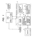
- Fig. 1 is a schematic view showing a three-dimensional scope system with a single camera installed on a vehicle body in accordance with a preferred embodiment of the present invention.
- a video camera 1 is a rearview camera installed on a vehicle body.
- the video camera 1 is a digital video camera having the resolution equivalent to or higher than 800 pixels ⁇ 600 pixels.
- a control unit 10, including a CPU and related memories (ROM, RAM, etc), is connected to control the image pickup operation of the video camera 1.
- Each still picture, obtained through the image pickup operation of the video camera 1, is sent to an image processing apparatus 2 which is connected to the video camera 1.
- the image processing apparatus 2 analyzes the data of still pictures obtained by the video camera 1 to form a stereoscopic picture image. More specifically, the image processing apparatus 2 comprises a picture memory 21, a feature point extracting section 22, a three-dimensional coordinate data calculating section 23, and a stereoscopic picture forming section 24.
- the picture memory 21 serves as a memory device for storing the digital data of still pictures obtained by the video camera 1.
- the feature point extracting section 22 serves as a means for extracting a feature point from the still picture of an obstacle based on the digital data stored in the picture memory 21.
- the three-dimensional coordinate data calculating section 23 serves as a means for calculating the position of the extracted feature point in a three-dimensional coordinate system.
- the stereoscopic picture forming section 24 serves as a means for forming a plan view or a side view based on the three-dimensional coordinate data obtained by three-dimensional coordinate data calculating section 23.
- the stereoscopic picture forming section 24 includes a viewpoint changing section 24' for forming a stereoscopic picture image to be picked up from an arbitrary viewpoint.
- a monitor 3 is connected to the image processing apparatus 2.
- the monitor 3 displays the stereoscopic picture image produced from the image processing apparatus 2.
- the control unit 10 performs the data communication with the image processing apparatus 2 and activates a warning device 11 based on the result of collision prediction.
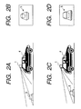
- Figs. 2A to 2D cooperatively illustrate the operation for successively obtaining still pictures of an obstacle by using the three-dimensional scope system with a single camera installed on a vehicle in accordance with the preferred embodiment of the present invention.
- Fig. 2A shows a traveling position where the video camera 1 mounted on a vehicle body 4 performs the image pickup operation of the obstacle 5.
- Fig. 2B shows a still picture of the obstacle 5 obtained at the traveling position shown in Fig. 2A.
- Fig. 2C shows a different traveling position where the vehicle body 4 approaches the obstacle 5 more closely.
- Fig. 2D shows a still picture of the obstacle 5 obtained at the traveling position shown in Fig. 2C.
- Fig. 3 shows an angular change of the video camera 1 corresponding to two successive image pickup operations of the obstacle 5.
- "H” represents the height of the video camera 1 measured from a ground level.
- ⁇ 0 represents an angle between the optical axis C of video camera 1 and the vertical line.
- "1" represents a vehicle traveling distance in the backward direction.
- Each of "H", ⁇ 0 and "1” is a known parameter.
- a feature point 6 of the obstacle 5 deviates by an angle ⁇ 1 with respect to the optical axis C of the video camera 1.
- the feature point 6 of the obstacle 5 deviates by an angle ⁇ 2 with respect to the optical axis C of the video camera 1.
- h represents the height of the feature point 6 of the obstacle 5
- h' represents a vertical distance from the video camera 1 to the feature point 6 of the obstacle 5.
- Both of h and h' are unknown parameters.
- Fig. 4 shows a still picture of the obstacle 5 displayed on the screen of the monitor 3.
- the feature point 6 is a singular point of the picture, such as an apex of a solid body, appearing on the screen.
- the above-described three-dimensional scope system operates in the following manner.
- Fig. 4 is a flowchart showing the operation of the three-dimensional scope system in accordance with the preferred embodiment of the present invention.
- the video camera 1 is mounted on the vehicle body 4 and directed to the rearward of the vehicle body 4 (refer to Fig. 2A).
- the control unit 10 controls the video camera 1 to perform the image pickup operation to obtain the still picture shown in Fig. 2B.
- the still picture shown in Fig. 2B is referred to as first picture.
- step S2 it is checked whether a predetermined time ⁇ t has passed or not. During this time interval, the vehicle moves backward and approaches the obstacle 5 as shown in Fig. 2C.
- video camera 1 again performs the image pickup operation to obtain the still picture shown in Fig. 2D.
- the still picture shown in Fig. 2D is referred to as second picture.
- the picture memory 21 stores both the first picture and the second picture.
- the control unit 10 obtains the vehicle traveling distance "1" based on the traveling speed "v" of the vehicle body 4 and the time interval ⁇ t between two image pickup operations.
- step S5 the control unit 10 causes the picture memory 21 to send the picture data stored to the feature point extracting portion 22.
- step S6 the control unit 10 causes the feature point extracting portion 22 to extract the feature points from the first and second pictures. Namely, a predetermined number of corresponding portions are searched by comparing the first and second picture data. This kind of searching operation can be done by using the pattern match processing. Alternatively, it is possible to apply the differential processing to the picture data obtained from the video camera 1 to detect the edges of the obstacle 5. Line segments connect the detected edges to obtain a wire frame image of the obstacle 5. Then, each apex of the obtained wire frame image is designated as a feature point. This processing is repeated for each of the pictures, thereby obtaining a plurality of feature points. Based on the comparison between the feature points of successively obtained still pictures, closest feature points are designated as corresponding or congruent points of two still pictures.
- step S7 the control unit 10 causes the three-dimensional coordinate data calculating section 23 to obtain the three-dimensional coordinate data representing the feature points.
- the three-dimensional coordinate data of the feature points are obtained based on the positional change amount of the corresponding points on the screen and also based on the vehicle traveling speed.
- a distance l1 represents a horizontal distance from the video camera 1 to the feature point 6 of the obstacle 5 in the first image pickup operation.
- a distance l2 represents a horizontal distance from the video camera 1 to the feature point 6 of the obstacle 5 in the second image pickup operation.
- l1 (H - h) ⁇ tan ( ⁇ 0 + ⁇ 1)
- l2 (H - h) ⁇ tan ( ⁇ 0 + ⁇ 2)
- H represents the height of the video camera 1
- h represents the height of the obstacle 5
- ⁇ 0 represents the angle of the optical axis C of the video camera 1
- ⁇ 1 represents the deviation angle of the feature point 6 with respect to the optical axis C in the first image pickup operation
- ⁇ 2 represents the deviation angle of the feature point 6 with respect to the optical axis C in the second image pickup operation.
- the deviation angles ⁇ 1 and ⁇ 2 can be obtained from the Y-axis coordinate values.
- the viewpoint changing section 24' is provided to form a stereoscopic picture image to be picked up from an arbitrary viewpoint.
- the control unit 10 causes the viewpoint changing section 4' to adjust or optimize the viewpoint.
- the viewpoint changing section 24' With the function of the viewpoint changing section 24', it becomes possible to shift or move the viewpoint to any other place, such as the infinite point or the driver's position, from the video camera 1. As a result, it becomes possible to emphasize the effect of stereoscopic image creation. By utilizing such a flexible image creation, it becomes possible to directly and accurately grasp the distance from the vehicle body 4 to the obstacle 5.
- step S9 the control unit 10 causes the stereoscopic picture forming section 24 to form or create a finalized stereoscopic picture image which is displayed on the monitor 3.
- the control unit 10 checks the positional relationship between the vehicle body 4 and obstacle 5 based on the three-dimensional information of them.
- the warning device 11 such as a buzzer, is actuated to caution a driver against a collision predictable from the approaching obstacle 5 (step S11). Instead of using the buzzer, it is preferable to generate warning sound or turn on a red indicator lamp.
- the preferred embodiment of the present invention provides a three-dimensional scope system with a single camera for vehicles.
- a single video camera is mounted on a vehicle body.
- the single video camera obtains two still pictures of a target successively at an appropriate time interval.
- the positional change of corresponding points are calculated with reference to the data of two still pictures thus obtained.
- the detected obstacle data such as distance, height and others, are calculated based on the positional change data on a screen and an actual vehicle traveling distance.
- a monitor displays the detected obstacle data in a stereoscopic or three-dimensional manner.
- the warning device is activated to caution a driver against a predictable collision. Accordingly, it becomes possible to measure the distance of the obstacle by using a single camera.
- the collision prediction can be performed at a low cost.
- the present invention provides a three-dimensional scope system with a single camera for vehicles.
- the three-dimensional scope system of the present invention comprises a single camera mounted on a vehicle body for successively obtaining two still pictures of a predetermined target at different vehicle traveling positions, a means for obtaining a vehicle traveling distance between the different vehicle traveling positions, a means for obtaining a positional change amount of at least one objective point of the target on a camera screen, and a means for obtaining three-dimensional coordinate data of the objective point based on the vehicle traveling distance and the positional change amount of the objective point on the screen.
- the present invention makes it possible to measure the obstacle position with a simplified arrangement. It becomes possible to prevent the vehicle body from colliding with an obstacle.
- the three-dimensional scope system of the present invention further comprises a means for forming a stereoscopic picture image based on the three-dimensional coordinate data of the objective point, and a monitor for displaying a resultant stereoscopic picture image.
- the present invention makes it possible to display the target in a stereoscopic manner.
- the means for forming the stereoscopic picture image includes a means for changing a viewpoint.
- the present invention makes it possible to flexibly display a stereoscopic picture image of the target to be image picked up from an arbitrary viewpoint. Thus, it becomes possible to emphasize the effect of stereoscopic image creation.
- the three-dimensional scope system of the present invention further comprises a means for generating the alarm when an obstacle is detected within a predetermined distance from the vehicle body.
- the present invention makes it possible to caution a driver against a collision predictable from the approaching obstacle.
- the above-described embodiment provides the image processing apparatus 2 separately from the control unit 10, it is needless to say that the image processing apparatus 2 and the control unit 10 can be integrated into a single computer-based control unit.
- all of the feature point extracting section 22, the three-dimensional coordinate data calculating section 23, and the stereoscopic picture forming section 24 can be replaced by the CPU of the control unit 10 when the CPU can operate as a means for perform the same functions thereof.
- the picture memory 21 functions as one of built-in memories in the control unit.
Landscapes
- Engineering & Computer Science (AREA)
- Multimedia (AREA)
- Physics & Mathematics (AREA)
- General Physics & Mathematics (AREA)
- Mechanical Engineering (AREA)
- Automation & Control Theory (AREA)
- Theoretical Computer Science (AREA)
- Electromagnetism (AREA)
- Human Computer Interaction (AREA)
- Signal Processing (AREA)
- Transportation (AREA)
- Radar, Positioning & Navigation (AREA)
- Remote Sensing (AREA)
- Computer Vision & Pattern Recognition (AREA)
- Closed-Circuit Television Systems (AREA)
- Image Processing (AREA)
- Measurement Of Optical Distance (AREA)
- Length Measuring Devices By Optical Means (AREA)
Abstract
Description
- The present invention relates to a three-dimensional scope system with a single camera for vehicles. More particularly, the three-dimensional scope system of the present invention is capable of obtaining a distance between a target and a vehicle body based on data of two still pictures of the target obtained at different vehicle traveling positions by using a single camera.
- Conventionally, two stereo cameras, which are mounted on a vehicle body, simultaneously perform the image pickup operation of an obstacle. Data of two still pictures obtained from the right and left cameras are used to detect corresponding or congruent points and to calculate the position of the obstacle based on the principle of triangulation.
- Figs. 7A to 7C schematically illustrates a conventional method for measuring the position of an obstacle by using stereo cameras mounted on a vehicle body. In Fig. 7A, a right stereo camera 7 and a left stereo camera 8, constituting a set of two stereo cameras, are installed on a front or rear side of a vehicle body 4. Figs. 7B and 7C respectively show two still pictures obtained by the right stereo camera 7 and the left camera 8. An image processing apparatus analyses the resultant data of two still pictures to obtain corresponding or congruent points. The distance between the vehicle body 4 and the obstacle 5 is calculated. When the distance between the vehicle body 4 and the obstacle 5 becomes less than a predetermined value, a buzzer is actuated or warning sound is generated to caution a driver against the obstacle.
- This kind of conventional stereo camera system is disadvantageous in that it requires two cameras and therefore the system cost increases.
- To solve the above-described problems of the conventional stereo camera system, the present invention has an aim to form and display a stereoscopic picture image of the obstacle based on the data of two still pictures of the obstacle successively obtained by a single video camera mounted on a vehicle body.
- The present invention provides a three-dimensional scope system with a single camera for vehicles. The three-dimensional scope system of the present invention comprises a single camera mounted on a vehicle body for successively obtaining two still pictures of a predetermined target at different vehicle traveling positions, a means for obtaining a vehicle traveling distance between the different vehicle traveling positions, a means for obtaining a positional change amount of at least one objective point of the target on a camera screen, and a means for obtaining three-dimensional coordinate data of the objective point based on the vehicle traveling distance and the positional change amount of the objective point on the screen. With this arrangement, the present invention makes it possible to obtain a stereoscopic picture image by using a single camera.
- Furthermore, it is preferable that the three-dimensional scope system of the present invention further comprises a means for forming a stereoscopic picture image based on the three-dimensional coordinate data of the objective point, and a monitor for displaying a resultant stereoscopic picture image. With this arrangement, the present invention makes it possible to display the target in a stereoscopic manner by using a single camera.
- Furthermore, it is preferable that the means for forming the stereoscopic picture image includes a means for changing a viewpoint. With this arrangement, the present invention makes it possible to flexibly display a stereoscopic picture image of the target to be image picked up from an arbitrary viewpoint.
- Furthermore, it is preferable that the three-dimensional scope system of the present invention further comprises a means for generating the alarm when an obstacle is detected within a predetermined distance from the vehicle body. With this arrangement, the present invention makes it possible to caution a driver against a collision predictable from the approaching obstacle.
- Furthermore, the present invention provides a processing method for a three-dimensional scope system with a single camera mounted on a vehicle body. The method comprising a first step of causing the single camera to successively obtain two still pictures of a predetermined target at different vehicle traveling positions, a second step of obtaining a positional change amount of at least one objective point of the target on a camera screen, a third step of obtaining three-dimensional coordinate data of the objective point based on a vehicle traveling distance between the different vehicle traveling positions and also based on the positional change amount of the objective point on the screen, and a fourth step of forming a stereoscopic picture image based on the three-dimensional coordinate data of the objective point.
- Preferably, the processing method of the present invention further comprises a step of generating the alarm when an obstacle is detected within a predetermined distance from the vehicle body.
- The above and other features and advantages of the present invention will become more apparent from the following detailed description of an exemplary embodiment and the accompanying drawings, in which:
- Fig. 1 is a schematic view showing a three-dimensional scope system with a single camera for vehicles in accordance with a preferred embodiment of the present invention;
- Fig. 2A is a side view showing the relationship between an obstacle and a rearview camera mounted on a vehicle body;
- Fig. 2B is a view showing a still picture obtained though the image pickup operation of the rearview camera mounted on the vehicle body;
- Fig. 2C is a side view showing the relationship between an obstacle and a rearview camera mounted on a vehicle body at a different vehicle traveling position;
- Fig. 2D is a view showing a still picture obtained though the image pickup operation of the rearview camera mounted on the vehicle body at the different vehicle traveling position;
- Fig. 3 is a view illustrating the measurement of the three-dimensional scope system with a single camera for vehicles in accordance with the preferred embodiment of the present invention;
- Fig. 4 is a view showing a displayed picture image of an obstacle which is formed by the three-dimensional scope system with a single camera in accordance with the preferred embodiment of the present invention;
- Fig. 5 is a flowchart showing the operation of the three-dimensional scope system with a single camera in accordance with the preferred embodiment of the present invention;
- Fig. 6 is a view showing a displayed picture image of the obstacle seen from above which is formed by the three-dimensional scope system with a single camera in accordance with the preferred embodiment of the present invention;
- Figs. 7A to 7C are views illustrating an obstacle detection in accordance with a conventional stereo camera system.
-
- Hereinafter, a preferred embodiment of the present invention will be explained with reference to Figs. 1 to 6. Identical parts are denoted by the same reference numerals throughout the views.
- A preferred embodiment of the present invention is a three-dimensional scope system with a single camera for vehicles. According to this three-dimensional scope system, a single rearview camera is mounted on a vehicle body. The rearview camera obtains two still pictures of a target successively at an appropriate time interval. The positional change of a corresponding point is calculated with reference to the data of two obtained still pictures. The detected obstacle data, such as distance, height and others, are calculated based on the positional change data on a screen and an actual vehicle traveling distance. A monitor displays the detected obstacle data in a stereoscopic manner. When the obstacle is located within a predetermined distance from the vehicle body, the alarm is generated to caution a driver against a predictable collision.
- Fig. 1 is a schematic view showing a three-dimensional scope system with a single camera installed on a vehicle body in accordance with a preferred embodiment of the present invention. In Fig. 1, a video camera 1 is a rearview camera installed on a vehicle body. The video camera 1 is a digital video camera having the resolution equivalent to or higher than 800 pixels × 600 pixels. A control unit 10, including a CPU and related memories (ROM, RAM, etc), is connected to control the image pickup operation of the video camera 1.
- Each still picture, obtained through the image pickup operation of the video camera 1, is sent to an image processing apparatus 2 which is connected to the video camera 1. The image processing apparatus 2 analyzes the data of still pictures obtained by the video camera 1 to form a stereoscopic picture image. More specifically, the image processing apparatus 2 comprises a picture memory 21, a feature point extracting section 22, a three-dimensional coordinate data calculating section 23, and a stereoscopic picture forming section 24.
- The picture memory 21 serves as a memory device for storing the digital data of still pictures obtained by the video camera 1. The feature point extracting section 22 serves as a means for extracting a feature point from the still picture of an obstacle based on the digital data stored in the picture memory 21. The three-dimensional coordinate data calculating section 23 serves as a means for calculating the position of the extracted feature point in a three-dimensional coordinate system. The stereoscopic picture forming section 24 serves as a means for forming a plan view or a side view based on the three-dimensional coordinate data obtained by three-dimensional coordinate data calculating section 23. The stereoscopic picture forming section 24 includes a viewpoint changing section 24' for forming a stereoscopic picture image to be picked up from an arbitrary viewpoint.
- A monitor 3 is connected to the image processing apparatus 2. The monitor 3 displays the stereoscopic picture image produced from the image processing apparatus 2. The control unit 10 performs the data communication with the image processing apparatus 2 and activates a warning device 11 based on the result of collision prediction.
- Figs. 2A to 2D cooperatively illustrate the operation for successively obtaining still pictures of an obstacle by using the three-dimensional scope system with a single camera installed on a vehicle in accordance with the preferred embodiment of the present invention. Fig. 2A shows a traveling position where the video camera 1 mounted on a vehicle body 4 performs the image pickup operation of the obstacle 5. Fig. 2B shows a still picture of the obstacle 5 obtained at the traveling position shown in Fig. 2A. Fig. 2C shows a different traveling position where the vehicle body 4 approaches the obstacle 5 more closely. Fig. 2D shows a still picture of the obstacle 5 obtained at the traveling position shown in Fig. 2C.
- Fig. 3 shows an angular change of the video camera 1 corresponding to two successive image pickup operations of the obstacle 5. In Fig. 3, "H" represents the height of the video camera 1 measured from a ground level. 0 represents an angle between the optical axis C of video camera 1 and the vertical line. "1" represents a vehicle traveling distance in the backward direction. Each of "H", 0 and "1" is a known parameter. At the first image pickup operation, a feature point 6 of the obstacle 5 deviates by an angle 1 with respect to the optical axis C of the video camera 1. At the second image pickup operation, the feature point 6 of the obstacle 5 deviates by an angle 2 with respect to the optical axis C of the video camera 1. Furthermore, "h" represents the height of the feature point 6 of the obstacle 5, and h' represents a vertical distance from the video camera 1 to the feature point 6 of the obstacle 5. Both of h and h' are unknown parameters. Fig. 4 shows a still picture of the obstacle 5 displayed on the screen of the monitor 3. The feature point 6 is a singular point of the picture, such as an apex of a solid body, appearing on the screen.
- According to the preferred embodiment of the present invention, the above-described three-dimensional scope system operates in the following manner.
- Fig. 4 is a flowchart showing the operation of the three-dimensional scope system in accordance with the preferred embodiment of the present invention.
- The video camera 1 is mounted on the vehicle body 4 and directed to the rearward of the vehicle body 4 (refer to Fig. 2A). In step S1, the control unit 10 controls the video camera 1 to perform the image pickup operation to obtain the still picture shown in Fig. 2B. The still picture shown in Fig. 2B is referred to as first picture. Then, in step S2, it is checked whether a predetermined time Δt has passed or not. During this time interval, the vehicle moves backward and approaches the obstacle 5 as shown in Fig. 2C. Then, in step S3, video camera 1 again performs the image pickup operation to obtain the still picture shown in Fig. 2D. The still picture shown in Fig. 2D is referred to as second picture.
- The picture memory 21 stores both the first picture and the second picture. In step S4, the control unit 10 obtains the vehicle traveling distance "1" based on the traveling speed "v" of the vehicle body 4 and the time interval Δt between two image pickup operations.
- Then, in step S5, the control unit 10 causes the picture memory 21 to send the picture data stored to the feature point extracting portion 22.
- Then, in step S6, the control unit 10 causes the feature point extracting portion 22 to extract the feature points from the first and second pictures. Namely, a predetermined number of corresponding portions are searched by comparing the first and second picture data. This kind of searching operation can be done by using the pattern match processing. Alternatively, it is possible to apply the differential processing to the picture data obtained from the video camera 1 to detect the edges of the obstacle 5. Line segments connect the detected edges to obtain a wire frame image of the obstacle 5. Then, each apex of the obtained wire frame image is designated as a feature point. This processing is repeated for each of the pictures, thereby obtaining a plurality of feature points. Based on the comparison between the feature points of successively obtained still pictures, closest feature points are designated as corresponding or congruent points of two still pictures.
- Then, in step S7, the control unit 10 causes the three-dimensional coordinate data calculating section 23 to obtain the three-dimensional coordinate data representing the feature points.
- Hereinafter, the method for calculating the three-dimensional coordinate data of the feature points will be explained with reference to Fig. 3. The three-dimensional coordinate data of the feature points are obtained based on the positional change amount of the corresponding points on the screen and also based on the vehicle traveling speed.
- For simplifying the explanation, it is assumed that the obstacle 5 is positioned on a central axis (i.e., Y axis) of the screen. The vehicle traveling distance "l" during two consecutive image pickup operations is expressed by the following equation.
- Meanwhile, a distance l1 represents a horizontal distance from the video camera 1 to the feature point 6 of the obstacle 5 in the first image pickup operation. Similarly, a distance l2 represents a horizontal distance from the video camera 1 to the feature point 6 of the obstacle 5 in the second image pickup operation. These distances l1 and l2 are expressed by the following equations.
- As a value (I1 -I2) represents the vehicle traveling distance, the following relationship is established.
- When L represents a constant determined by the screen size, the Y-axis coordinate value of the feature point 6 can be expressed in the following manner.
- Accordingly, 1 and 2 are expressed in the following manner.
- In other words, the deviation angles 1 and 2 can be obtained from the Y-axis coordinate values. The height "h" of the feature point 6 is expressed in the following manner.
- When the feature point 6 is not located on the Y axis, it is desirable to shift or project the feature point 6 on the Y axis and then to obtain the X-axis coordinate value of the feature point. When "d" represents a distance from the video camera 1 to the feature point projected on the Y axis and "x1" represents the X-axis coordinate value of the feature point 6 on the screen, a lateral or horizontal distance "a" from the central axis is expressed by the following equation.
- Accordingly, all of the horizontal distance "l1" from the video camera 1 to the objective point, the height "h" of the objective point, and the lateral distance "a" can be obtained. Thus, it becomes possible to draw a stereoscopic picture image.
- Based on the coordinate values of the feature points, it becomes possible to create or form a stereoscopic picture image similar to those disclosed in Figs. 2B, 2D and 4 which are obtained (i.e., image picked up) by the video camera 1. However, to surely grasp the distance, it is also desirable to form and display another picture image showing the side of the vehicle body 4 as shown in Fig. 3, or showing the top of the vehicle body 4 as shown in Fig. 5.
- According to this embodiment, the viewpoint changing section 24' is provided to form a stereoscopic picture image to be picked up from an arbitrary viewpoint. Namely, in step S8, the control unit 10 causes the viewpoint changing section 4' to adjust or optimize the viewpoint.
- With the function of the viewpoint changing section 24', it becomes possible to shift or move the viewpoint to any other place, such as the infinite point or the driver's position, from the video camera 1. As a result, it becomes possible to emphasize the effect of stereoscopic image creation. By utilizing such a flexible image creation, it becomes possible to directly and accurately grasp the distance from the vehicle body 4 to the obstacle 5.
- Then, in step S9, the control unit 10 causes the stereoscopic picture forming section 24 to form or create a finalized stereoscopic picture image which is displayed on the monitor 3.
- When the vehicle body 4 moves backward, the control unit 10 checks the positional relationship between the vehicle body 4 and obstacle 5 based on the three-dimensional information of them. When the distance between the vehicle body 4 and obstacle 5 becomes shorter than a predetermined value (i.e., YES in step S10), the warning device 11, such as a buzzer, is actuated to caution a driver against a collision predictable from the approaching obstacle 5 (step S11). Instead of using the buzzer, it is preferable to generate warning sound or turn on a red indicator lamp.
- According to the above-described embodiment, only two still pictures are used to create or form a stereoscopic picture image. However, when the image processing apparatus has a sufficiently high speed in the image processing, it is possible to obtain animated or dynamic picture images by speedily converting continuously obtained still picture data into serial stereoscopic picture images.
- As apparent from the foregoing description, the preferred embodiment of the present invention provides a three-dimensional scope system with a single camera for vehicles. According to this three-dimensional scope system, a single video camera is mounted on a vehicle body. The single video camera obtains two still pictures of a target successively at an appropriate time interval. The positional change of corresponding points are calculated with reference to the data of two still pictures thus obtained. The detected obstacle data, such as distance, height and others, are calculated based on the positional change data on a screen and an actual vehicle traveling distance. A monitor displays the detected obstacle data in a stereoscopic or three-dimensional manner. When the obstacle is located within a predetermined distance from the vehicle body, the warning device is activated to caution a driver against a predictable collision. Accordingly, it becomes possible to measure the distance of the obstacle by using a single camera. The collision prediction can be performed at a low cost.
- As explained in the foregoing description, the present invention provides a three-dimensional scope system with a single camera for vehicles. The three-dimensional scope system of the present invention comprises a single camera mounted on a vehicle body for successively obtaining two still pictures of a predetermined target at different vehicle traveling positions, a means for obtaining a vehicle traveling distance between the different vehicle traveling positions, a means for obtaining a positional change amount of at least one objective point of the target on a camera screen, and a means for obtaining three-dimensional coordinate data of the objective point based on the vehicle traveling distance and the positional change amount of the objective point on the screen. The present invention makes it possible to measure the obstacle position with a simplified arrangement. It becomes possible to prevent the vehicle body from colliding with an obstacle.
- Furthermore, it is preferable that the three-dimensional scope system of the present invention further comprises a means for forming a stereoscopic picture image based on the three-dimensional coordinate data of the objective point, and a monitor for displaying a resultant stereoscopic picture image. With this arrangement, the present invention makes it possible to display the target in a stereoscopic manner.
- Furthermore, it is preferable that the means for forming the stereoscopic picture image includes a means for changing a viewpoint. With this arrangement, the present invention makes it possible to flexibly display a stereoscopic picture image of the target to be image picked up from an arbitrary viewpoint. Thus, it becomes possible to emphasize the effect of stereoscopic image creation.
- Furthermore, it is preferable that the three-dimensional scope system of the present invention further comprises a means for generating the alarm when an obstacle is detected within a predetermined distance from the vehicle body. With this arrangement, the present invention makes it possible to caution a driver against a collision predictable from the approaching obstacle.
- Although the above-described embodiment provides the image processing apparatus 2 separately from the control unit 10, it is needless to say that the image processing apparatus 2 and the control unit 10 can be integrated into a single computer-based control unit. For example, all of the feature point extracting section 22, the three-dimensional coordinate data calculating section 23, and the stereoscopic picture forming section 24 can be replaced by the CPU of the control unit 10 when the CPU can operate as a means for perform the same functions thereof. In this case, the picture memory 21 functions as one of built-in memories in the control unit.
- This invention may be embodied in several forms without departing from the spirit of essential characteristics thereof. The present embodiment as described is therefore intended to be only illustrative and not restrictive, since the scope of the invention is defined by the appended claims rather than by the description preceding them. All changes that fall within the metes and bounds of the claims, or equivalents of such metes and bounds, are therefore intended to be embraced by the claims.
Claims (6)
- A three-dimensional scope system comprising with a single camera for vehicles,
characterized bya single camera (1) mounted on a vehicle body (4) for successively obtaining two still pictures of a predetermined target (5) at different vehicle traveling positions;a means (10) for obtaining a vehicle traveling distance (l) between said different vehicle traveling positions;a means (10, 21, 22) for obtaining a positional change amount of at least one objective point (6) of said target (5) on a camera screen; anda means (10, 23) for obtaining three-dimensional coordinate data of said objective point (6) based on the vehicle traveling distance (l) and said positional change amount of the objective point on the screen. - The three-dimensional scope system with a single camera in accordance with claim 1, further comprising:a means (10, 24) for forming a stereoscopic picture image based on said three-dimensional coordinate data of said objective point (6); anda monitor (3) for displaying a resultant stereoscopic picture image.
- The three-dimensional scope system with a single camera in accordance with claim 2, wherein said means (10, 24) for forming said stereoscopic picture image includes a means (24') for changing a viewpoint.
- The three-dimensional scope system with a single camera in accordance with any one of claims 1 to 3, further comprising a means (11) for generating the alarm when an obstacle (5) is detected within a predetermined distance from said vehicle body (4).
- A processing method for a three-dimensional scope system with a single camera mounted on a vehicle body,
characterized bya step (S1-S3) of causing said single camera to successively obtain two still pictures of a predetermined target at different vehicle traveling positions;a step (S5-S6) of obtaining a positional change amount of at least one objective point of said target on a camera screen;a step (S7) of obtaining three-dimensional coordinate data of said objective point based on a vehicle traveling distance between said different vehicle traveling positions and also based on said positional change amount of the objective point on the screen; anda step (S9) of forming a stereoscopic picture image based on said three-dimensional coordinate data of said objective point. - The processing method for a three-dimensional scope system with a single camera in accordance with claim 5, further comprising a step (S10-S11) of generating the alarm when an obstacle is detected within a predetermined distance from said vehicle body.
Applications Claiming Priority (2)
| Application Number | Priority Date | Filing Date | Title |
|---|---|---|---|
| JP33572298 | 1998-11-26 | ||
| JP10335722A JP2000161915A (en) | 1998-11-26 | 1998-11-26 | On-vehicle single-camera stereoscopic vision system |
Publications (3)
| Publication Number | Publication Date |
|---|---|
| EP1005234A2 true EP1005234A2 (en) | 2000-05-31 |
| EP1005234A3 EP1005234A3 (en) | 2002-05-22 |
| EP1005234B1 EP1005234B1 (en) | 2006-06-21 |
Family
ID=18291747
Family Applications (1)
| Application Number | Title | Priority Date | Filing Date |
|---|---|---|---|
| EP99309257A Expired - Lifetime EP1005234B1 (en) | 1998-11-26 | 1999-11-19 | Three-dimensional scope system for vehicles with a single camera |
Country Status (5)
| Country | Link |
|---|---|
| US (1) | US6172601B1 (en) |
| EP (1) | EP1005234B1 (en) |
| JP (1) | JP2000161915A (en) |
| CN (1) | CN1144025C (en) |
| DE (1) | DE69932021T2 (en) |
Cited By (12)
| Publication number | Priority date | Publication date | Assignee | Title |
|---|---|---|---|---|
| EP1231110A2 (en) * | 2001-02-09 | 2002-08-14 | Matsushita Electric Industrial Co., Ltd. | Picture synthesizing apparatus |
| EP1270329A3 (en) * | 2001-06-18 | 2003-12-17 | Matsushita Electric Industrial Co., Ltd. | Monitoring system |
| EP1403139A1 (en) | 2002-09-30 | 2004-03-31 | Aisin Seiki Kabushiki Kaisha | Movable body circumstance monitoring apparatus |
| EP1403138A1 (en) | 2002-09-30 | 2004-03-31 | Aisin Seiki Kabushiki Kaisha | Movable body circumstance monitoring apparatus |
| EP1403137A1 (en) | 2002-09-30 | 2004-03-31 | Aisin Seiki Kabushiki Kaisha | Movable body circumstance monitoring apparatus |
| EP1405776A1 (en) * | 2002-09-30 | 2004-04-07 | Aisin Seiki Kabushiki Kaisha | Movable body circumstance monitoring apparatus |
| EP1298001A3 (en) * | 2001-09-26 | 2004-04-28 | CLARION Co., Ltd. | Method and apparatus for monitoring vehicle rear, and signal processor |
| EP1431120A1 (en) * | 2002-12-18 | 2004-06-23 | Aisin Seiki Kabushiki Kaisha | Movable body circumstance monitoring apparatus |
| EP1462762A1 (en) * | 2003-03-25 | 2004-09-29 | Aisin Seiki Kabushiki Kaisha | Circumstance monitoring device of a vehicle |
| EP1486377A2 (en) * | 2003-05-28 | 2004-12-15 | Aisin Seiki Kabushiki Kaisha | Movable body surrounding monitoring apparatus |
| US8384762B2 (en) | 2008-09-19 | 2013-02-26 | Mbda Uk Limited | Method and apparatus for displaying stereographic images of a region |
| CN107430821A (en) * | 2015-04-02 | 2017-12-01 | 株式会社电装 | Image processing apparatus |
Families Citing this family (134)
| Publication number | Priority date | Publication date | Assignee | Title |
|---|---|---|---|---|
| US5910854A (en) | 1993-02-26 | 1999-06-08 | Donnelly Corporation | Electrochromic polymeric solid films, manufacturing electrochromic devices using such solid films, and processes for making such solid films and devices |
| US5668663A (en) | 1994-05-05 | 1997-09-16 | Donnelly Corporation | Electrochromic mirrors and devices |
| US6891563B2 (en) * | 1996-05-22 | 2005-05-10 | Donnelly Corporation | Vehicular vision system |
| US6172613B1 (en) * | 1998-02-18 | 2001-01-09 | Donnelly Corporation | Rearview mirror assembly incorporating vehicle information display |
| US8294975B2 (en) * | 1997-08-25 | 2012-10-23 | Donnelly Corporation | Automotive rearview mirror assembly |
| US6326613B1 (en) | 1998-01-07 | 2001-12-04 | Donnelly Corporation | Vehicle interior mirror assembly adapted for containing a rain sensor |
| US6124886A (en) | 1997-08-25 | 2000-09-26 | Donnelly Corporation | Modular rearview mirror assembly |
| US8288711B2 (en) | 1998-01-07 | 2012-10-16 | Donnelly Corporation | Interior rearview mirror system with forwardly-viewing camera and a control |
| US6445287B1 (en) | 2000-02-28 | 2002-09-03 | Donnelly Corporation | Tire inflation assistance monitoring system |
| US6693517B2 (en) | 2000-04-21 | 2004-02-17 | Donnelly Corporation | Vehicle mirror assembly communicating wirelessly with vehicle accessories and occupants |
| US6477464B2 (en) | 2000-03-09 | 2002-11-05 | Donnelly Corporation | Complete mirror-based global-positioning system (GPS) navigation solution |
| US6329925B1 (en) * | 1999-11-24 | 2001-12-11 | Donnelly Corporation | Rearview mirror assembly with added feature modular display |
| US6531959B1 (en) * | 1999-07-13 | 2003-03-11 | Honda Giken Kogyo Kabushiki Kaisha | Position detecting device |
| DE60009000T2 (en) * | 1999-10-21 | 2005-03-10 | Matsushita Electric Industrial Co., Ltd., Kadoma | Parking assistance system |
| US6917693B1 (en) * | 1999-12-20 | 2005-07-12 | Ford Global Technologies, Llc | Vehicle data acquisition and display assembly |
| AU2001243285A1 (en) * | 2000-03-02 | 2001-09-12 | Donnelly Corporation | Video mirror systems incorporating an accessory module |
| WO2007053710A2 (en) | 2005-11-01 | 2007-05-10 | Donnelly Corporation | Interior rearview mirror with display |
| US7167796B2 (en) | 2000-03-09 | 2007-01-23 | Donnelly Corporation | Vehicle navigation system for use with a telematics system |
| US7370983B2 (en) | 2000-03-02 | 2008-05-13 | Donnelly Corporation | Interior mirror assembly with display |
| US6535114B1 (en) * | 2000-03-22 | 2003-03-18 | Toyota Jidosha Kabushiki Kaisha | Method and apparatus for environment recognition |
| EP1167120B1 (en) * | 2000-06-30 | 2014-08-27 | Panasonic Corporation | Rendering device for parking aid |
| US7581859B2 (en) | 2005-09-14 | 2009-09-01 | Donnelly Corp. | Display device for exterior rearview mirror |
| US7255451B2 (en) | 2002-09-20 | 2007-08-14 | Donnelly Corporation | Electro-optic mirror cell |
| ES2287266T3 (en) | 2001-01-23 | 2007-12-16 | Donnelly Corporation | IMPROVED VEHICLE LIGHTING SYSTEM. |
| US6424272B1 (en) * | 2001-03-30 | 2002-07-23 | Koninklijke Philips Electronics, N.V. | Vehicular blind spot vision system |
| US6636258B2 (en) | 2001-10-19 | 2003-10-21 | Ford Global Technologies, Llc | 360° vision system for a vehicle |
| JP3704706B2 (en) * | 2002-03-13 | 2005-10-12 | オムロン株式会社 | 3D monitoring device |
| US6918674B2 (en) * | 2002-05-03 | 2005-07-19 | Donnelly Corporation | Vehicle rearview mirror system |
| US7329013B2 (en) * | 2002-06-06 | 2008-02-12 | Donnelly Corporation | Interior rearview mirror system with compass |
| WO2003105099A1 (en) | 2002-06-06 | 2003-12-18 | Donnelly Corporation | Interior rearview mirror system with compass |
| ATE414380T1 (en) * | 2002-07-25 | 2008-11-15 | Koninkl Philips Electronics Nv | DISPLAY DEVICE |
| AU2003278863A1 (en) | 2002-09-20 | 2004-04-08 | Donnelly Corporation | Mirror reflective element assembly |
| WO2004103772A2 (en) | 2003-05-19 | 2004-12-02 | Donnelly Corporation | Mirror assembly for vehicle |
| US7310177B2 (en) | 2002-09-20 | 2007-12-18 | Donnelly Corporation | Electro-optic reflective element assembly |
| DE10244148A1 (en) * | 2002-09-23 | 2004-04-08 | Daimlerchrysler Ag | Method and device for video-based observation and measurement of the lateral surroundings of a vehicle |
| US9063633B2 (en) * | 2006-03-30 | 2015-06-23 | Arjuna Indraeswaran Rajasingham | Virtual navigation system for virtual and real spaces |
| US20050222769A1 (en) * | 2003-06-26 | 2005-10-06 | Jefferey Simon | Modular sensor system |
| US20050031169A1 (en) * | 2003-08-09 | 2005-02-10 | Alan Shulman | Birds eye view virtual imaging for real time composited wide field of view |
| US7446924B2 (en) * | 2003-10-02 | 2008-11-04 | Donnelly Corporation | Mirror reflective element assembly including electronic component |
| US7308341B2 (en) | 2003-10-14 | 2007-12-11 | Donnelly Corporation | Vehicle communication system |
| DE10349823A1 (en) * | 2003-10-24 | 2005-05-25 | Valeo Schalter Und Sensoren Gmbh | Method for measuring distances between a moving motor vehicle and objects |
| DE10394295T5 (en) * | 2003-10-31 | 2012-02-09 | Fujitsu Ltd. | Distance calculation device and calculation program |
| BRPI0416395A (en) * | 2003-11-11 | 2007-05-08 | Technikus Ag | device for recording gait and / or traffic situations and process for evaluating these annotations |
| JP4513318B2 (en) * | 2003-12-10 | 2010-07-28 | 日産自動車株式会社 | Rear side image control apparatus and method |
| JP4638143B2 (en) * | 2003-12-26 | 2011-02-23 | 富士重工業株式会社 | Vehicle driving support device |
| GB0405014D0 (en) * | 2004-03-05 | 2004-04-07 | Qinetiq Ltd | Movement control system |
| WO2005088970A1 (en) * | 2004-03-11 | 2005-09-22 | Olympus Corporation | Image generation device, image generation method, and image generation program |
| DE102005015088B4 (en) * | 2004-04-02 | 2015-06-18 | Denso Corporation | Vehicle environment monitoring system |
| EP1748654A4 (en) * | 2004-04-27 | 2013-01-02 | Panasonic Corp | Circumference display of vehicle |
| DE102004028763A1 (en) * | 2004-06-16 | 2006-01-19 | Daimlerchrysler Ag | Andockassistent |
| JP4002919B2 (en) * | 2004-09-02 | 2007-11-07 | 技研トラステム株式会社 | Moving body height discrimination device |
| EP1650085A1 (en) * | 2004-10-22 | 2006-04-26 | IEE INTERNATIONAL ELECTRONICS & ENGINEERING S.A. | Occupant-sensing imaging system |
| JP4657765B2 (en) * | 2005-03-09 | 2011-03-23 | 三菱自動車工業株式会社 | Nose view system |
| EP1883855B1 (en) | 2005-05-16 | 2011-07-20 | Donnelly Corporation | Vehicle mirror assembly with indicia at reflective element |
| JP4650935B2 (en) * | 2005-06-23 | 2011-03-16 | アルパイン株式会社 | Vehicle driving support device |
| DE102005036782A1 (en) * | 2005-08-02 | 2007-02-15 | Magna Donnelly Gmbh & Co. Kg | Operation method for image evaluation system, involves determination of image shift vector from image difference of object feature images whereby camera movement vector and image shift vector are fed to computer unit as input data |
| CN100386595C (en) * | 2005-08-18 | 2008-05-07 | 中国科学院半导体研究所 | Early-warning method and apparatus for anticollision of cars |
| MX2008011219A (en) | 2006-03-09 | 2008-09-11 | Gentex Corp | Vehicle rearview assembly including a high intensity display. |
| CN101210813B (en) * | 2006-12-26 | 2011-05-04 | 上海乐金广电电子有限公司 | Vehicular monitoring device |
| CN101408423B (en) * | 2007-10-09 | 2011-05-18 | 财团法人工业技术研究院 | Method for detecting angle of image viewfinding device and vehicle collision alarming system thereof |
| JP2009180536A (en) * | 2008-01-29 | 2009-08-13 | Omron Corp | Image processing apparatus, image processing method, and program |
| US8154418B2 (en) | 2008-03-31 | 2012-04-10 | Magna Mirrors Of America, Inc. | Interior rearview mirror system |
| US8280621B2 (en) | 2008-04-15 | 2012-10-02 | Caterpillar Inc. | Vehicle collision avoidance system |
| US20090259399A1 (en) * | 2008-04-15 | 2009-10-15 | Caterpillar Inc. | Obstacle detection method and system |
| US8170787B2 (en) * | 2008-04-15 | 2012-05-01 | Caterpillar Inc. | Vehicle collision avoidance system |
| US9487144B2 (en) | 2008-10-16 | 2016-11-08 | Magna Mirrors Of America, Inc. | Interior mirror assembly with display |
| JP5067632B2 (en) * | 2008-11-28 | 2012-11-07 | アイシン精機株式会社 | Bird's-eye image generator |
| CN101441076B (en) * | 2008-12-29 | 2010-06-02 | 东软集团股份有限公司 | Method and device for detecting barrier |
| JP4775474B2 (en) | 2009-03-31 | 2011-09-21 | カシオ計算機株式会社 | Imaging apparatus, imaging control method, and program |
| JP4664427B2 (en) * | 2009-09-16 | 2011-04-06 | 富士通株式会社 | Distance calculation device |
| KR101448411B1 (en) | 2010-08-19 | 2014-10-07 | 닛산 지도우샤 가부시키가이샤 | Three-dimensional object detection device and three -dimensional object detection method |
| JP5783243B2 (en) * | 2011-02-21 | 2015-09-24 | 日産自動車株式会社 | Periodic stationary object detection apparatus and periodic stationary object detection method |
| JP5153021B2 (en) * | 2011-03-14 | 2013-02-27 | パナソニック株式会社 | Imaging apparatus, imaging method, and program |
| JP5124671B2 (en) * | 2011-06-07 | 2013-01-23 | 株式会社小松製作所 | Work vehicle perimeter monitoring device |
| WO2012169355A1 (en) * | 2011-06-09 | 2012-12-13 | アイシン精機株式会社 | Image generation device |
| US9092676B2 (en) * | 2011-08-02 | 2015-07-28 | Nissan Motor Co., Ltd. | Object detector and object detection method |
| WO2013029606A2 (en) * | 2011-08-29 | 2013-03-07 | Bergische Universität Wuppertal | Method, arrangement and driving assistance system for determining the spatial distribution of objects relative to a vehicle |
| JP5914791B2 (en) * | 2011-11-30 | 2016-05-11 | 株式会社シーマイクロ | Collision detection device |
| DE102011087894A1 (en) * | 2011-12-07 | 2013-06-13 | Robert Bosch Gmbh | Method and vehicle assistance system for active warning and / or navigation aid for avoiding a collision of a vehicle body part and / or a vehicle wheel with an object |
| US9297641B2 (en) * | 2011-12-12 | 2016-03-29 | Mobileye Vision Technologies Ltd. | Detection of obstacles at night by analysis of shadows |
| DE102012201051A1 (en) * | 2012-01-25 | 2013-07-25 | Robert Bosch Gmbh | Procedure for driving assistance and driver assistance system |
| US8879139B2 (en) | 2012-04-24 | 2014-11-04 | Gentex Corporation | Display mirror assembly |
| US9798936B2 (en) | 2012-07-31 | 2017-10-24 | Harman International Industries, Incorporated | System and method for detecting obstacles using a single camera |
| DE102013200409A1 (en) * | 2013-01-14 | 2014-07-17 | Robert Bosch Gmbh | A method and apparatus for monitoring an environment of a vehicle and method for performing emergency braking |
| CN103105174B (en) * | 2013-01-29 | 2016-06-15 | 四川长虹佳华信息产品有限责任公司 | A kind of vehicle-mounted outdoor scene safety navigation method based on AR augmented reality |
| US9598018B2 (en) | 2013-03-15 | 2017-03-21 | Gentex Corporation | Display mirror assembly |
| DE102013010233B4 (en) | 2013-06-18 | 2018-08-30 | Volkswagen Aktiengesellschaft | A method of displaying environmental information in a vehicle and a display system for a vehicle |
| KR101439052B1 (en) * | 2013-09-05 | 2014-09-05 | 현대자동차주식회사 | Apparatus and method for detecting obstacle |
| US9575315B2 (en) | 2013-09-24 | 2017-02-21 | Gentex Corporation | Display mirror assembly |
| US9511715B2 (en) | 2014-01-31 | 2016-12-06 | Gentex Corporation | Backlighting assembly for display for reducing cross-hatching |
| EP3119643B1 (en) | 2014-03-21 | 2018-05-23 | Gentex Corporation | Tri-modal display mirror assembly |
| CN106163873B (en) | 2014-04-01 | 2019-04-26 | 金泰克斯公司 | Automatic display mirror assembly |
| US9342747B2 (en) * | 2014-04-14 | 2016-05-17 | Bendix Commercial Vehicle Systems Llc | Vehicle driver assistance apparatus for assisting a vehicle driver in maneuvering the vehicle relative to an object |
| US9694751B2 (en) | 2014-09-19 | 2017-07-04 | Gentex Corporation | Rearview assembly |
| US9694752B2 (en) | 2014-11-07 | 2017-07-04 | Gentex Corporation | Full display mirror actuator |
| US10071689B2 (en) | 2014-11-13 | 2018-09-11 | Gentex Corporation | Rearview mirror system with a display |
| KR101997815B1 (en) | 2014-12-03 | 2019-07-08 | 젠텍스 코포레이션 | Display mirror assembly |
| USD746744S1 (en) | 2014-12-05 | 2016-01-05 | Gentex Corporation | Rearview device |
| US9744907B2 (en) | 2014-12-29 | 2017-08-29 | Gentex Corporation | Vehicle vision system having adjustable displayed field of view |
| US9720278B2 (en) | 2015-01-22 | 2017-08-01 | Gentex Corporation | Low cost optical film stack |
| JP2018512593A (en) * | 2015-04-10 | 2018-05-17 | ローベルト ボツシユ ゲゼルシヤフト ミツト ベシユレンクテル ハフツングRobert Bosch Gmbh | Object position measurement with in-vehicle camera using vehicle movement data |
| EP3286038A4 (en) | 2015-04-20 | 2018-04-25 | Gentex Corporation | Rearview assembly with applique |
| CN107614324B (en) | 2015-05-18 | 2020-11-27 | 金泰克斯公司 | Complete display rearview device |
| EP3310618A4 (en) | 2015-06-22 | 2018-07-04 | Gentex Corporation | System and method for processing streamed video images to correct for flicker of amplitude-modulated lights |
| US9718404B2 (en) * | 2015-10-01 | 2017-08-01 | Ford Global Technologies, LLCS | Parking obstruction locator and height estimator |
| USD797627S1 (en) | 2015-10-30 | 2017-09-19 | Gentex Corporation | Rearview mirror device |
| CN108349436B (en) | 2015-10-30 | 2019-12-20 | 金泰克斯公司 | Rear-view device |
| WO2017075420A1 (en) | 2015-10-30 | 2017-05-04 | Gentex Corporation | Toggle paddle |
| USD798207S1 (en) | 2015-10-30 | 2017-09-26 | Gentex Corporation | Rearview mirror assembly |
| USD800618S1 (en) | 2015-11-02 | 2017-10-24 | Gentex Corporation | Toggle paddle for a rear view device |
| CN105882516A (en) * | 2015-11-13 | 2016-08-24 | 乐卡汽车智能科技(北京)有限公司 | Vehicle collision early-warning method and device, and vehicle |
| JP6629425B2 (en) * | 2016-03-14 | 2020-01-15 | 日立建機株式会社 | Mining work machine |
| USD845851S1 (en) | 2016-03-31 | 2019-04-16 | Gentex Corporation | Rearview device |
| USD817238S1 (en) | 2016-04-29 | 2018-05-08 | Gentex Corporation | Rearview device |
| NL2016718B1 (en) * | 2016-05-02 | 2017-11-10 | Cyclomedia Tech B V | A method for improving position information associated with a collection of images. |
| US10025138B2 (en) | 2016-06-06 | 2018-07-17 | Gentex Corporation | Illuminating display with light gathering structure |
| DE102016111079A1 (en) * | 2016-06-17 | 2017-12-21 | Valeo Schalter Und Sensoren Gmbh | Method for object height detection of an object in the environment of a motor vehicle and driver assistance system |
| DE102016213377B4 (en) * | 2016-07-21 | 2023-11-16 | Volkswagen Aktiengesellschaft | Method for clearance height detection |
| KR20180039942A (en) * | 2016-10-11 | 2018-04-19 | 현대오트론 주식회사 | Apparatus and method for driving ultrasonic sensor |
| USD809984S1 (en) | 2016-12-07 | 2018-02-13 | Gentex Corporation | Rearview assembly |
| USD854473S1 (en) | 2016-12-16 | 2019-07-23 | Gentex Corporation | Rearview assembly |
| US20180191966A1 (en) | 2016-12-30 | 2018-07-05 | Gentex Corporation | Full display mirror with on-demand spotter view |
| US20180270413A1 (en) * | 2017-03-15 | 2018-09-20 | Kabushiki Kaisha Toshiba | Processing apparatus and processing system |
| US10735638B2 (en) | 2017-03-17 | 2020-08-04 | Gentex Corporation | Dual display reverse camera system |
| US10737618B2 (en) * | 2017-04-10 | 2020-08-11 | Advanced Semiconductor Engineering, Inc. | Device and method for identifying relative position between objects |
| JP6790998B2 (en) * | 2017-04-28 | 2020-11-25 | 株式会社Soken | Obstacle detector and control device |
| CN109872530B (en) * | 2017-12-05 | 2022-02-15 | 广州腾讯科技有限公司 | Road condition information generation method, vehicle-mounted terminal and server |
| CN110667474B (en) * | 2018-07-02 | 2021-02-26 | 北京四维图新科技股份有限公司 | General obstacle detection method and device and automatic driving system |
| CN109085608A (en) * | 2018-09-12 | 2018-12-25 | 奇瑞汽车股份有限公司 | Obstacles around the vehicle detection method and device |
| CN111031231A (en) * | 2018-10-10 | 2020-04-17 | 富泰华工业(深圳)有限公司 | Electronic device and method for judging three-dimensional object |
| CN112572281A (en) * | 2019-09-27 | 2021-03-30 | 北京市商汤科技开发有限公司 | Light intensity adjusting method and device, electronic equipment and storage medium |
| CN111353453B (en) * | 2020-03-06 | 2023-08-25 | 北京百度网讯科技有限公司 | Obstacle detection method and device for vehicle |
| KR20220072146A (en) * | 2020-11-25 | 2022-06-02 | 삼성전자주식회사 | Electronic apparatus and controlling method thereof |
| WO2023218293A1 (en) * | 2022-05-10 | 2023-11-16 | C.R.F. Società Consortile Per Azioni | Vehicle equipped with a system for detecting the distance of an object in front of the vehicle on the basis of a communication of a v2x type with other vehicles and on the basis of a detection of position |
Citations (3)
| Publication number | Priority date | Publication date | Assignee | Title |
|---|---|---|---|---|
| US5473364A (en) * | 1994-06-03 | 1995-12-05 | David Sarnoff Research Center, Inc. | Video technique for indicating moving objects from a movable platform |
| US5646614A (en) * | 1993-10-25 | 1997-07-08 | Mercedes-Benz Ag | System for monitoring the front or rear parking space of a motor vehicle |
| US6114951A (en) * | 1996-12-27 | 2000-09-05 | Fuji Jukogyo Kabushiki Kaisha | Vehicle collision preventing apparatus |
Family Cites Families (12)
| Publication number | Priority date | Publication date | Assignee | Title |
|---|---|---|---|---|
| US4214266A (en) * | 1978-06-19 | 1980-07-22 | Myers Charles H | Rear viewing system for vehicles |
| US4872051A (en) * | 1987-10-01 | 1989-10-03 | Environmental Research Institute Of Michigan | Collision avoidance alarm system |
| JP2843079B2 (en) * | 1989-12-22 | 1999-01-06 | 本田技研工業株式会社 | Driving path determination method |
| JPH0648242A (en) * | 1992-06-01 | 1994-02-22 | Nippondenso Co Ltd | End position display for vehicle |
| JP3263699B2 (en) * | 1992-12-22 | 2002-03-04 | 三菱電機株式会社 | Driving environment monitoring device |
| US5670935A (en) * | 1993-02-26 | 1997-09-23 | Donnelly Corporation | Rearview vision system for vehicle including panoramic view |
| JP3064759B2 (en) * | 1993-09-28 | 2000-07-12 | 株式会社日立製作所 | Apparatus for monitoring surroundings of vehicle, driving support system for vehicle, and driving support apparatus |
| JP3287117B2 (en) * | 1994-07-05 | 2002-05-27 | 株式会社日立製作所 | Environment recognition device for vehicles using imaging device |
| US5889878A (en) * | 1994-07-29 | 1999-03-30 | Kabushiki Kaisha Toshiba | Moving object image pickup apparatus |
| JP3246243B2 (en) * | 1994-12-26 | 2002-01-15 | いすゞ自動車株式会社 | Lane departure warning device |
| JPH09142236A (en) * | 1995-11-17 | 1997-06-03 | Mitsubishi Electric Corp | Periphery monitoring method and device for vehicle, and trouble deciding method and device for periphery monitoring device |
| JPH10222679A (en) * | 1997-02-04 | 1998-08-21 | Toyota Motor Corp | Vehicle image processor |
-
1998
- 1998-11-26 JP JP10335722A patent/JP2000161915A/en active Pending
-
1999
- 1999-11-15 US US09/440,139 patent/US6172601B1/en not_active Expired - Lifetime
- 1999-11-19 EP EP99309257A patent/EP1005234B1/en not_active Expired - Lifetime
- 1999-11-19 DE DE69932021T patent/DE69932021T2/en not_active Expired - Fee Related
- 1999-11-26 CN CNB991228367A patent/CN1144025C/en not_active Expired - Fee Related
Patent Citations (3)
| Publication number | Priority date | Publication date | Assignee | Title |
|---|---|---|---|---|
| US5646614A (en) * | 1993-10-25 | 1997-07-08 | Mercedes-Benz Ag | System for monitoring the front or rear parking space of a motor vehicle |
| US5473364A (en) * | 1994-06-03 | 1995-12-05 | David Sarnoff Research Center, Inc. | Video technique for indicating moving objects from a movable platform |
| US6114951A (en) * | 1996-12-27 | 2000-09-05 | Fuji Jukogyo Kabushiki Kaisha | Vehicle collision preventing apparatus |
Cited By (19)
| Publication number | Priority date | Publication date | Assignee | Title |
|---|---|---|---|---|
| EP1231110A3 (en) * | 2001-02-09 | 2004-09-08 | Matsushita Electric Industrial Co., Ltd. | Picture synthesizing apparatus |
| EP1231110A2 (en) * | 2001-02-09 | 2002-08-14 | Matsushita Electric Industrial Co., Ltd. | Picture synthesizing apparatus |
| US7058207B2 (en) | 2001-02-09 | 2006-06-06 | Matsushita Electric Industrial Co. Ltd. | Picture synthesizing apparatus |
| EP1270329A3 (en) * | 2001-06-18 | 2003-12-17 | Matsushita Electric Industrial Co., Ltd. | Monitoring system |
| US8201199B2 (en) | 2001-06-18 | 2012-06-12 | Panasonic Corporation | Monitoring system |
| US7429998B2 (en) | 2001-09-26 | 2008-09-30 | Clarion Co., Ltd. | Method and apparatus for monitoring vehicle rear, and signal processor |
| EP1298001A3 (en) * | 2001-09-26 | 2004-04-28 | CLARION Co., Ltd. | Method and apparatus for monitoring vehicle rear, and signal processor |
| EP1403137A1 (en) | 2002-09-30 | 2004-03-31 | Aisin Seiki Kabushiki Kaisha | Movable body circumstance monitoring apparatus |
| EP1405776A1 (en) * | 2002-09-30 | 2004-04-07 | Aisin Seiki Kabushiki Kaisha | Movable body circumstance monitoring apparatus |
| EP1403138A1 (en) | 2002-09-30 | 2004-03-31 | Aisin Seiki Kabushiki Kaisha | Movable body circumstance monitoring apparatus |
| EP1403139A1 (en) | 2002-09-30 | 2004-03-31 | Aisin Seiki Kabushiki Kaisha | Movable body circumstance monitoring apparatus |
| EP1431120A1 (en) * | 2002-12-18 | 2004-06-23 | Aisin Seiki Kabushiki Kaisha | Movable body circumstance monitoring apparatus |
| US7379564B2 (en) | 2002-12-18 | 2008-05-27 | Aisin Seiki Kabushiki Kaisha | Movable body circumstance monitoring apparatus |
| EP1462762A1 (en) * | 2003-03-25 | 2004-09-29 | Aisin Seiki Kabushiki Kaisha | Circumstance monitoring device of a vehicle |
| FR2853121A1 (en) * | 2003-03-25 | 2004-10-01 | Imra Europe Sa | DEVICE FOR MONITORING THE SURROUNDINGS OF A VEHICLE |
| EP1486377A2 (en) * | 2003-05-28 | 2004-12-15 | Aisin Seiki Kabushiki Kaisha | Movable body surrounding monitoring apparatus |
| EP1486377A3 (en) * | 2003-05-28 | 2005-10-12 | Aisin Seiki Kabushiki Kaisha | Movable body surrounding monitoring apparatus |
| US8384762B2 (en) | 2008-09-19 | 2013-02-26 | Mbda Uk Limited | Method and apparatus for displaying stereographic images of a region |
| CN107430821A (en) * | 2015-04-02 | 2017-12-01 | 株式会社电装 | Image processing apparatus |
Also Published As
| Publication number | Publication date |
|---|---|
| EP1005234A3 (en) | 2002-05-22 |
| CN1255624A (en) | 2000-06-07 |
| US6172601B1 (en) | 2001-01-09 |
| JP2000161915A (en) | 2000-06-16 |
| DE69932021T2 (en) | 2007-07-12 |
| EP1005234B1 (en) | 2006-06-21 |
| DE69932021D1 (en) | 2006-08-03 |
| CN1144025C (en) | 2004-03-31 |
Similar Documents
| Publication | Publication Date | Title |
|---|---|---|
| EP1005234A2 (en) | Three-dimensional scope system for vehicles with a single camera | |
| US11315348B2 (en) | Vehicular vision system with object detection | |
| EP1264734B1 (en) | Vehicle surroundings monitoring apparatus | |
| EP2544449B1 (en) | Vehicle perimeter monitoring device | |
| JP3596314B2 (en) | Object edge position measuring device and moving object traffic judging device | |
| JP3263699B2 (en) | Driving environment monitoring device | |
| JP4876118B2 (en) | Three-dimensional object appearance detection device | |
| US8988525B2 (en) | System and method for providing guidance information to a driver of a vehicle | |
| US7652686B2 (en) | Device for image detecting objects, people or similar in the area surrounding a vehicle | |
| JP2004114977A (en) | Moving body periphery monitoring device | |
| KR20020033817A (en) | Device for assisting automobile driver | |
| EP1403137B1 (en) | Movable body circumstance monitoring apparatus | |
| KR20060021922A (en) | Two camera based obstacle detection method and device | |
| JP4948338B2 (en) | Inter-vehicle distance measuring device | |
| JP2002314989A (en) | Peripheral monitor for vehicle | |
| JPH1144533A (en) | Preceding vehicle detector | |
| JP2007280387A (en) | Method and device for detecting object movement | |
| JP3612821B2 (en) | In-vehicle distance measuring device | |
| JPH0771916A (en) | On-vehicle distance measuring device | |
| JP3586938B2 (en) | In-vehicle distance measuring device | |
| WO2008037473A1 (en) | Park assist system visually marking up dangerous objects | |
| CN111043977B (en) | Method for determining a relative parameter of a first vehicle with respect to a second vehicle | |
| CN215495425U (en) | Compound eye imaging system and vehicle using same | |
| JP3393767B2 (en) | Obstacle detection device for vehicles | |
| JP2002202136A (en) | Observation apparatus for state in circumference of vehicle |
Legal Events
| Date | Code | Title | Description |
|---|---|---|---|
| PUAI | Public reference made under article 153(3) epc to a published international application that has entered the european phase |
Free format text: ORIGINAL CODE: 0009012 |
|
| AK | Designated contracting states |
Kind code of ref document: A2 Designated state(s): AT BE CH CY DE DK ES FI FR GB GR IE IT LI LU MC NL PT SE |
|
| AX | Request for extension of the european patent |
Free format text: AL;LT;LV;MK;RO;SI |
|
| PUAL | Search report despatched |
Free format text: ORIGINAL CODE: 0009013 |
|
| AX | Request for extension of the european patent |
Free format text: AL;LT;LV;MK;RO;SI |
|
| RIC1 | Information provided on ipc code assigned before grant |
Free format text: 7H 04N 13/02 A, 7B 60Q 1/48 B, 7B 60Q 1/52 B, 7H 04N 13/00 B |
|
| 17P | Request for examination filed |
Effective date: 20020809 |
|
| AKX | Designation fees paid |
Designated state(s): DE FR GB |
|
| 17Q | First examination report despatched |
Effective date: 20041015 |
|
| GRAP | Despatch of communication of intention to grant a patent |
Free format text: ORIGINAL CODE: EPIDOSNIGR1 |
|
| GRAS | Grant fee paid |
Free format text: ORIGINAL CODE: EPIDOSNIGR3 |
|
| GRAA | (expected) grant |
Free format text: ORIGINAL CODE: 0009210 |
|
| AK | Designated contracting states |
Kind code of ref document: B1 Designated state(s): DE FR GB |
|
| REG | Reference to a national code |
Ref country code: GB Ref legal event code: FG4D |
|
| REF | Corresponds to: |
Ref document number: 69932021 Country of ref document: DE Date of ref document: 20060803 Kind code of ref document: P |
|
| ET | Fr: translation filed | ||
| PLBE | No opposition filed within time limit |
Free format text: ORIGINAL CODE: 0009261 |
|
| STAA | Information on the status of an ep patent application or granted ep patent |
Free format text: STATUS: NO OPPOSITION FILED WITHIN TIME LIMIT |
|
| 26N | No opposition filed |
Effective date: 20070322 |
|
| PGFP | Annual fee paid to national office [announced via postgrant information from national office to epo] |
Ref country code: DE Payment date: 20071115 Year of fee payment: 9 |
|
| PGFP | Annual fee paid to national office [announced via postgrant information from national office to epo] |
Ref country code: GB Payment date: 20071114 Year of fee payment: 9 Ref country code: FR Payment date: 20071108 Year of fee payment: 9 |
|
| GBPC | Gb: european patent ceased through non-payment of renewal fee |
Effective date: 20081119 |
|
| REG | Reference to a national code |
Ref country code: FR Ref legal event code: ST Effective date: 20090731 |
|
| PG25 | Lapsed in a contracting state [announced via postgrant information from national office to epo] |
Ref country code: DE Free format text: LAPSE BECAUSE OF NON-PAYMENT OF DUE FEES Effective date: 20090603 |
|
| PG25 | Lapsed in a contracting state [announced via postgrant information from national office to epo] |
Ref country code: GB Free format text: LAPSE BECAUSE OF NON-PAYMENT OF DUE FEES Effective date: 20081119 |
|
| PG25 | Lapsed in a contracting state [announced via postgrant information from national office to epo] |
Ref country code: FR Free format text: LAPSE BECAUSE OF NON-PAYMENT OF DUE FEES Effective date: 20081130 |