EP1003428B1 - Breast surgery apparatus - Google Patents
Breast surgery apparatus Download PDFInfo
- Publication number
- EP1003428B1 EP1003428B1 EP98935921A EP98935921A EP1003428B1 EP 1003428 B1 EP1003428 B1 EP 1003428B1 EP 98935921 A EP98935921 A EP 98935921A EP 98935921 A EP98935921 A EP 98935921A EP 1003428 B1 EP1003428 B1 EP 1003428B1
- Authority
- EP
- European Patent Office
- Prior art keywords
- tissue
- cutting
- elongated member
- incision
- cutting means
- Prior art date
- Legal status (The legal status is an assumption and is not a legal conclusion. Google has not performed a legal analysis and makes no representation as to the accuracy of the status listed.)
- Expired - Lifetime
Links
Images


Classifications
-
- A—HUMAN NECESSITIES
- A61—MEDICAL OR VETERINARY SCIENCE; HYGIENE
- A61B—DIAGNOSIS; SURGERY; IDENTIFICATION
- A61B10/00—Other methods or instruments for diagnosis, e.g. instruments for taking a cell sample, for biopsy, for vaccination diagnosis; Sex determination; Ovulation-period determination; Throat striking implements
- A61B10/02—Instruments for taking cell samples or for biopsy
- A61B10/0233—Pointed or sharp biopsy instruments
- A61B10/0266—Pointed or sharp biopsy instruments means for severing sample
-
- A—HUMAN NECESSITIES
- A61—MEDICAL OR VETERINARY SCIENCE; HYGIENE
- A61B—DIAGNOSIS; SURGERY; IDENTIFICATION
- A61B17/00—Surgical instruments, devices or methods, e.g. tourniquets
- A61B17/22—Implements for squeezing-off ulcers or the like on the inside of inner organs of the body; Implements for scraping-out cavities of body organs, e.g. bones; Calculus removers; Calculus smashing apparatus; Apparatus for removing obstructions in blood vessels, not otherwise provided for
- A61B17/221—Gripping devices in the form of loops or baskets for gripping calculi or similar types of obstructions
-
- A—HUMAN NECESSITIES
- A61—MEDICAL OR VETERINARY SCIENCE; HYGIENE
- A61B—DIAGNOSIS; SURGERY; IDENTIFICATION
- A61B17/00—Surgical instruments, devices or methods, e.g. tourniquets
- A61B17/32—Surgical cutting instruments
- A61B17/320016—Endoscopic cutting instruments, e.g. arthroscopes, resectoscopes
-
- A—HUMAN NECESSITIES
- A61—MEDICAL OR VETERINARY SCIENCE; HYGIENE
- A61B—DIAGNOSIS; SURGERY; IDENTIFICATION
- A61B17/00—Surgical instruments, devices or methods, e.g. tourniquets
- A61B17/32—Surgical cutting instruments
- A61B17/3205—Excision instruments
- A61B17/32056—Surgical snare instruments
-
- A—HUMAN NECESSITIES
- A61—MEDICAL OR VETERINARY SCIENCE; HYGIENE
- A61B—DIAGNOSIS; SURGERY; IDENTIFICATION
- A61B10/00—Other methods or instruments for diagnosis, e.g. instruments for taking a cell sample, for biopsy, for vaccination diagnosis; Sex determination; Ovulation-period determination; Throat striking implements
- A61B10/0041—Detection of breast cancer
-
- A—HUMAN NECESSITIES
- A61—MEDICAL OR VETERINARY SCIENCE; HYGIENE
- A61B—DIAGNOSIS; SURGERY; IDENTIFICATION
- A61B17/00—Surgical instruments, devices or methods, e.g. tourniquets
- A61B17/02—Surgical instruments, devices or methods, e.g. tourniquets for holding wounds open; Tractors
- A61B17/0218—Surgical instruments, devices or methods, e.g. tourniquets for holding wounds open; Tractors for minimally invasive surgery
-
- A—HUMAN NECESSITIES
- A61—MEDICAL OR VETERINARY SCIENCE; HYGIENE
- A61B—DIAGNOSIS; SURGERY; IDENTIFICATION
- A61B17/00—Surgical instruments, devices or methods, e.g. tourniquets
- A61B17/32—Surgical cutting instruments
- A61B17/3205—Excision instruments
- A61B17/3207—Atherectomy devices working by cutting or abrading; Similar devices specially adapted for non-vascular obstructions
- A61B17/320725—Atherectomy devices working by cutting or abrading; Similar devices specially adapted for non-vascular obstructions with radially expandable cutting or abrading elements
-
- A—HUMAN NECESSITIES
- A61—MEDICAL OR VETERINARY SCIENCE; HYGIENE
- A61B—DIAGNOSIS; SURGERY; IDENTIFICATION
- A61B18/00—Surgical instruments, devices or methods for transferring non-mechanical forms of energy to or from the body
- A61B18/04—Surgical instruments, devices or methods for transferring non-mechanical forms of energy to or from the body by heating
- A61B18/12—Surgical instruments, devices or methods for transferring non-mechanical forms of energy to or from the body by heating by passing a current through the tissue to be heated, e.g. high-frequency current
- A61B18/14—Probes or electrodes therefor
- A61B18/1482—Probes or electrodes therefor having a long rigid shaft for accessing the inner body transcutaneously in minimal invasive surgery, e.g. laparoscopy
-
- A—HUMAN NECESSITIES
- A61—MEDICAL OR VETERINARY SCIENCE; HYGIENE
- A61B—DIAGNOSIS; SURGERY; IDENTIFICATION
- A61B17/00—Surgical instruments, devices or methods, e.g. tourniquets
- A61B17/00234—Surgical instruments, devices or methods, e.g. tourniquets for minimally invasive surgery
- A61B2017/00287—Bags for minimally invasive surgery
-
- A—HUMAN NECESSITIES
- A61—MEDICAL OR VETERINARY SCIENCE; HYGIENE
- A61B—DIAGNOSIS; SURGERY; IDENTIFICATION
- A61B17/00—Surgical instruments, devices or methods, e.g. tourniquets
- A61B2017/00743—Type of operation; Specification of treatment sites
- A61B2017/00796—Breast surgery
-
- A—HUMAN NECESSITIES
- A61—MEDICAL OR VETERINARY SCIENCE; HYGIENE
- A61B—DIAGNOSIS; SURGERY; IDENTIFICATION
- A61B17/00—Surgical instruments, devices or methods, e.g. tourniquets
- A61B2017/00743—Type of operation; Specification of treatment sites
- A61B2017/00796—Breast surgery
- A61B2017/008—Removal of tumors
-
- A—HUMAN NECESSITIES
- A61—MEDICAL OR VETERINARY SCIENCE; HYGIENE
- A61B—DIAGNOSIS; SURGERY; IDENTIFICATION
- A61B17/00—Surgical instruments, devices or methods, e.g. tourniquets
- A61B17/22—Implements for squeezing-off ulcers or the like on the inside of inner organs of the body; Implements for scraping-out cavities of body organs, e.g. bones; Calculus removers; Calculus smashing apparatus; Apparatus for removing obstructions in blood vessels, not otherwise provided for
- A61B17/221—Gripping devices in the form of loops or baskets for gripping calculi or similar types of obstructions
- A61B2017/2212—Gripping devices in the form of loops or baskets for gripping calculi or similar types of obstructions having a closed distal end, e.g. a loop
-
- A—HUMAN NECESSITIES
- A61—MEDICAL OR VETERINARY SCIENCE; HYGIENE
- A61B—DIAGNOSIS; SURGERY; IDENTIFICATION
- A61B17/00—Surgical instruments, devices or methods, e.g. tourniquets
- A61B17/32—Surgical cutting instruments
- A61B17/320016—Endoscopic cutting instruments, e.g. arthroscopes, resectoscopes
- A61B2017/32004—Endoscopic cutting instruments, e.g. arthroscopes, resectoscopes having a laterally movable cutting member at its most distal end which remains within the contours of said end
-
- A—HUMAN NECESSITIES
- A61—MEDICAL OR VETERINARY SCIENCE; HYGIENE
- A61B—DIAGNOSIS; SURGERY; IDENTIFICATION
- A61B17/00—Surgical instruments, devices or methods, e.g. tourniquets
- A61B17/32—Surgical cutting instruments
- A61B17/320068—Surgical cutting instruments using mechanical vibrations, e.g. ultrasonic
- A61B2017/320072—Working tips with special features, e.g. extending parts
- A61B2017/320074—Working tips with special features, e.g. extending parts blade
-
- A—HUMAN NECESSITIES
- A61—MEDICAL OR VETERINARY SCIENCE; HYGIENE
- A61B—DIAGNOSIS; SURGERY; IDENTIFICATION
- A61B18/00—Surgical instruments, devices or methods for transferring non-mechanical forms of energy to or from the body
- A61B18/04—Surgical instruments, devices or methods for transferring non-mechanical forms of energy to or from the body by heating
- A61B18/12—Surgical instruments, devices or methods for transferring non-mechanical forms of energy to or from the body by heating by passing a current through the tissue to be heated, e.g. high-frequency current
- A61B18/14—Probes or electrodes therefor
- A61B2018/1405—Electrodes having a specific shape
- A61B2018/1407—Loop
-
- A—HUMAN NECESSITIES
- A61—MEDICAL OR VETERINARY SCIENCE; HYGIENE
- A61B—DIAGNOSIS; SURGERY; IDENTIFICATION
- A61B18/00—Surgical instruments, devices or methods for transferring non-mechanical forms of energy to or from the body
- A61B18/18—Surgical instruments, devices or methods for transferring non-mechanical forms of energy to or from the body by applying electromagnetic radiation, e.g. microwaves
- A61B18/20—Surgical instruments, devices or methods for transferring non-mechanical forms of energy to or from the body by applying electromagnetic radiation, e.g. microwaves using laser
- A61B18/22—Surgical instruments, devices or methods for transferring non-mechanical forms of energy to or from the body by applying electromagnetic radiation, e.g. microwaves using laser the beam being directed along or through a flexible conduit, e.g. an optical fibre; Couplings or hand-pieces therefor
- A61B2018/2238—Surgical instruments, devices or methods for transferring non-mechanical forms of energy to or from the body by applying electromagnetic radiation, e.g. microwaves using laser the beam being directed along or through a flexible conduit, e.g. an optical fibre; Couplings or hand-pieces therefor with means for selectively laterally deflecting the tip of the fibre
-
- A—HUMAN NECESSITIES
- A61—MEDICAL OR VETERINARY SCIENCE; HYGIENE
- A61B—DIAGNOSIS; SURGERY; IDENTIFICATION
- A61B90/00—Instruments, implements or accessories specially adapted for surgery or diagnosis and not covered by any of the groups A61B1/00 - A61B50/00, e.g. for luxation treatment or for protecting wound edges
- A61B90/39—Markers, e.g. radio-opaque or breast lesions markers
-
- A—HUMAN NECESSITIES
- A61—MEDICAL OR VETERINARY SCIENCE; HYGIENE
- A61B—DIAGNOSIS; SURGERY; IDENTIFICATION
- A61B90/00—Instruments, implements or accessories specially adapted for surgery or diagnosis and not covered by any of the groups A61B1/00 - A61B50/00, e.g. for luxation treatment or for protecting wound edges
- A61B90/40—Apparatus fixed or close to patients specially adapted for providing an aseptic surgical environment
Definitions
- This invention relates to surgical apparatus for obtaining a subcutaneous target mass having varied shape and dimension.
- Modern medical diagnostics increasingly rely on complex imaging technologies to identify abnormal conditions and/or masses within the human body.
- Such technologies as magnetic resonance imaging (MRI), ultrasonics, computerized axial tomography (CAT scan), and mammogram x-rays, aid medical personnel in the identification of areas within the body exhibiting potentially dangerous, abnormal biological activity.
- MRI magnetic resonance imaging
- CAT scan computerized axial tomography
- mammogram x-rays aid medical personnel in the identification of areas within the body exhibiting potentially dangerous, abnormal biological activity.
- the beneficial aspect of these technologies is their ability to image biological structures interior to the human body, providing a non-invasive tool useful in facilitating preliminary diagnosis and treatment of abnormalities.
- Detected subcutaneous biological growths, masses, etc. once identified generally require complete surgical excision or at the very least an open biopsy procedure.
- One type of specimen retrieval is performed with needle aspiration devices. These devices have a needle with an end hole. The needle is advanced to a desired location where a sample specimen is obtained via suction. Size and quality of specimens obtained by these devices are often poor, requiring multiple sampling of each desired target mass. Moreover, tissue encountered along the path to the desired location is unavoidably removed. A hollow channel is created upon withdrawal of the device from the patient, thereby allowing "seeding" of the hollow channel removal tract with abnormal cells.
- Some needle systems utilize an enlarged needle end hole, creating a boring probe which obtains a greater portion of tissue. This lessens the likelihood that the specimen will be too small but increases the amount of surface scarring due to the larger size incision required.
- Needle side cutting devices have a blade extending around the circumference of a hollow needle shaft. The shaft and blade are axially rotated around the skin entry site, allowing a larger overall specimen to be excised. Target tissue is sliced and a non-contiguous specimen is obtained due to the spiral blade path. While these needle side cutting devices facilitate capture of larger sample specimens, they require resection of a relatively large core of tissue between the incision and the specimen desired to be resected. Additionally, needle side cut devices result in irregularly shaped specimens and subcutaneous cavities having irregular and/or bleeding margins.
- WO-A-95/02370 which forms the basis for the preamble of claim 1, discloses a diathermy tunneling catheter device which tunnels through a carcinoma and the excised tissues may be removed by forceps or flushing into the stomach.
- US-A-5,370,647 describes a tissue and organ extractor for use during laparoscopic surgical procedures and discloses in relation to Figure 12 an enveloping means including a flexible waterproof web material which has an opening mouth so that tissue or organs can enter a rib portion of the envelope means.
- US-A-4,997,435 describes a percutaneous catheter having an encapsulating receptacle for removing calculi, such as kidney and gall stones.
- the known devices are particularly ill suited in retrieving tissue masses from the female breast, due to the interest in preserving cosmetic integrity of the surface tissue as well as the inability of the known devices to remove most masses/calcifications during a single application.
- This invention provides surgical apparatus where the size and shape of subcutaneous tissue identified for excision is minimally dependent on dimensions of the percutaneous incision.
- the apparatus has specific utility in breast surgery.
- This invention provides surgical apparatus for excision of percutaneous breast tissue.
- the apparatus has the capability to pass through an incision substantially smaller than the maximum percutaneous target specimen dimension occupying an excision site.
- the surgical apparatus preferably cuts the target tissue with an electro-cauterizing, circular array of flexible cutting blades, preferably collecting the specimen within the periphery of an expandable blade path; thus the complete growth is preferably obtained in a single procedure.
- the tissue is preferably returned as a complete specimen or, alternatively, in segments within a snaring membrane.
- a recovery sheath is preferably positioned to further encase and compress the blade array upon contraction.
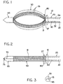
- the illustrated embodiment of surgical apparatus 10 includes an inner rotatable shaft 20, a tubular recovery sheath 25, a snaring membrane 30, a circular array of radially flexible and expandable cutting blades generally designated 50, a membrane drawstring 80, a membrane mouth section 27 of recovery sheath 25, a power source 15 and a tissue piercing member 65.
- Membrane 30 preferably has an inner surface 32 coaxially parallel with shaft 20, and an outer surface 34. Inner surface 32 of membrane 30 preferably slidably facingly contacts the outside surface 22 of shaft 20. Membrane 30 is adjustably positioned in either the distal or proximate direction through the proximate end of shaft 20.
- Tubular recovery sheath 25 preferably includes a distal pleated mouth section 27, an outer surface 45, and an inner surface 60 facingly coaxially contacting membrane 30. Inner surface 60 slidably engages outer surface 34 of membrane 30. Shaft 20 defines a rotational axis 12.
- Shaft 20 rotates as denoted by arrow 12.
- Rotatable shaft 20 of surgical apparatus 10 is preferably rotated manually, through mechanical hand control.
- shaft 20 may be operably linked with an electrical motor, not shown, which may be driven by power source 15.
- Circular cutting blade 50 includes individual flexible blades 55 which are preferably anchored between piercing member 65 and proximate end of shaft 20. Blades 55 are preferably electro-cauterizing, heated by electrical power source 15.
- the materials utilized to construct surgical apparatus 10 are preferably radiopaque to be visible using modern medical imaging systems.
- surgical apparatus 10 is shown with individual flexible blades 55 in their non-expandable, tissue insertion orientation. In this insertion orientation the blades are parallel with and of slightly smaller diameter than tubular recovery sheath 25.
- Tubular recovery sheath 25 includes a snaring membrane 30 having a mouth section 27 and a drawstring 80, for drawing membrane 30 closed once it has been opened.
- Drawstring 80 is positioned along the distal margin of mouth section 27.
- Mouth section 27 of membrane 30 expands outwardly in response to pulling of a polyvinyl tab or ripcord upon reaching the excision site.
- the polyvinyl tab or ripcord is preferably at the end of shaft 20 to the right, which is not shown in the drawing. The polyvinyl tab or ripcord is not visible in the drawing.
- Recovery sheath 25 is preferably advanced over circular array of cutting blades 50 and preferably secured in place around the cutting blades and the excised specimen by pulling the drawstring towards the proximate end of shaft 20.
- piercing segment 65 is formed to separate subcutaneous tissue in the path between the surface incision and the growth.
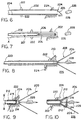
- FIG. 3 and Figure 4 show a modification of the embodiment of surgical apparatus 10 illustrated in Figures 1 and 2.
- shaft 20 includes an interior channel 21 extending forwardly through the center of the cutting blade circular array 50 and connecting with piercing member 65.
- a shaft stem section which is not shown connects to a dye port 70 in piercing member 65 for optional delivery of marking fluid to subcutaneous areas.
- Dye port 70 enables operators of apparatus 10 to deliver marking substances to the subcutaneous excision site.
- a titanium clip can be ejected from a clip fastening surface 75 for marking excision sites for future medical imaging analysis.
- the circular array 50 of cutting blades 55 expands radially upon relative movement of shaft 20 in the direction of piercing member 65, defining a cutting orientation.
- Flexible cutting blades 55 are preferably electro-cauterizing, cutting as they outwardly expand and as they rotate after radially outward expansion.
- the target tissue growth is separated from the surrounding subcutaneous breast tissue and remains within the periphery of the circular blade path.
- FIG 5 Use of the apparatus in excising subcutaneous breast target tissue growths is shown in Figure 5.
- the edges of a surgical site where a growth has been removed is indicated as 100; removal of the growth has created subcutaneous cavity 105.
- subcutaneous cavity 105 is separated from a surface incision 110 by an excision distance 95.
- percutaneous tissue is cut to produce an incision 110.
- a piercing member 65 of surgical apparatus 10 is placed at incision 110.
- An excision path is created by forcing piercing member 65 through the subcutaneous breast tissue between the percutaneous incision 110 and the identified target tissue growth.
- the target tissue growth is the desired excision site which is visualized via a medical imaging system such as ultrasound or mammography.
- the tip of surgical apparatus 10 is advanced until the piercing segment passes through the growth to be excised.
- Membrane 30 is then advanced over the circular array of cutting blades 50 and secured by pulling integral drawstring 80 to the right in Figure 5 towards the end of shaft 20.
- Drawstring 80 secures the distal margin of membrane 30.
- the mouth 27 of sheath 25 is expanded by the polyvinyl pull tab when drawn towards the end of shaft 20.
- Circular array of cutting blades 55, now encased by membrane 30, is drawn into the mouth of snaring sheath 25 and removed from subcutaneous cavity 105.
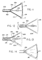
- a plurality of guide struts generally designated 206 are advanced through a skin surface incision and past a target tissue mass 228 via a tubular housing defining an extrication channel.
- guide struts 206 are inserted through the surface incision and moved to a position to define a conically shaped desired excision margin resecting the target tissue mass 228, shown in Figure 11.
- the extension and configuration of struts 206 from the surface incision past target mass 228 creates a gradually expanding subcutaneous retrieval path referred to as a conical penumbra 208.
- an electro-cauterizing cutting snare 214 is advanced along guide struts 206, creating a conically shaped excision margin.
- the cutting snare 214 is advanced beyond the length of the guide struts 206 to where cutting snare 214 is drawn closed by pulling an integral drawstring towards the exterior of the skin.
- a mouth of sheath 216 is advanced along the defined extrication channel and expanded by pulling the polyvinyl pull tab which is not shown.
- guide struts 206 are enveloped by snaring sheath 216 and may be removed from the subcutaneous cavity through the extrication channel.
- apparatus 200 includes a support conduit designated generally 202 and axially elongated skin cutting means 204 having a cutting blade 205 which is insertable through support conduit 202 as illustrated generally in Figure 6.
- Skin cutting means 204 and particularly cutting blade 205 serve to make a suitable incision in the skin, preferably in the human breast designated generally 226 in Figure 24 where the skin is designated 224 in the drawing figures including Figure 6 and Figure 24.
- the incision is made to provide access to a target tissue mass designated generally 228 in the drawings which has been previously identified preferably using x-ray mammographic techniques as being dangerous and hence to be removed.
- skin cutting means 204 is preferably withdrawn axially through support conduit 202, moving to the left in Figure 6, and support means designated generally 207 and having a plurality of support members designated generally 206 is inserted axially through support conduit 202 and into the sub-cutaneous tissue 226 of the breast as indicated generally in Figure 7, with the direction of travel of support means 207 indicated generally by arrow A in Figure 7.
- support members 206 of support means 207 are inserted into the sub-cutaneous tissue 226, support members expand 206 radially due to influence of resilient spring means 210, illustrated in dotted lines in Figure 8 and forming a portion of support means 207 to a position where support members 206 define a conical penumbra enveloping target tissue mass 228.
- the conical penumbra 208 defines planes of incision for removal of target tissue mass 228 and a medically advisable amount of surrounding sub-cutaneous healthy tissue 226.
- remote tips 209 of support members 206 define a circle which in turn defines the base of conical penumbra 208. Remaining, proximate ends of support members 206 are pivotally connected to a supporting shaft, not numbered in the drawings, for pivoting rotation thereabout in response to spring 210.
- a pair of tissue cutting wire loops 214 are positioned about the bases of support members 206, as illustrated generally in Figure 9, and are supported by and emerge from respective support catheters 212, also illustrated in Figure 9.
- Support catheters 212 are sufficiently rigid that when force is applied in the axial direction to support catheters 212 is indicated by arrows B and B' in Figure 9, support catheters 212 move to the right in Figure 9 advancing tissue cutting wire loops 214 along the outer periphery of support members 204 as depicted generally in Figure 10.
- tissue cutting wires 214 As support catheters 212 are moved to the right in Figures 9 and 10, additional lengths of tissue cutting wires 214 is supplied through support catheters 212 so that tissue cutting wires 214, which are in the form of loops about the exterior surfaces of support members 206 as illustrated in Figure 10, can enlarge as the circumference of the conical penumbra, measured about the slant surface of the conical penumbra defined by support members 206 as illustrated in Figure 10, increases.
- Support catheters 212 are urged to the right in Figure 10 until tissue cutting wire loops 214 pass the remote tips 209 of support members 206 and define a pair of essentially coincident and in any event concentric circles forming the base of conical penumbra 208.
- tissue cutting wire loops 214 Once tissue cutting wire loops 214 have reached this position due to movement of support catheters 212, the wire forming tissue cutting wire loops 214 are drawn to the left, through respective support catheters 212. This causes the respective tissue cutting wire loops 214 each to cinch together as the wires are withdrawn as indicated generally by arrows C, C' in Figure 11. As the tissue cutting wires are drawn to the left in Figure 11 through respective support catheters 212, the wire loops each cinch together thereby cutting circular incisions through the sub-cutaneous tissue; this action is illustrated generally in Figure 11 where the respective tissue cutting wire loops are shown partially, but not completely, cinched. Two wire loops are preferable, for symmetrical application of force.
- the conical penumbra 208 defines planes of incision created by action of tissue cutting wire loops 214 where those planes of incision are shown in dotted lines in Figure 12. Note that two dotted lines are shown at the extreme right of Figure 12 to indicate that two circular planar incisions created by action of respective tissue cutting wire loops 214. Desirably, these two circular planar incisions are essentially congruent one with another.
- tissue containment bag structure 216 is advanced outwardly of support conduit 202, around the outer periphery of support means 207 and particularly support members 206.
- Tissue containment bag 216 preferably has a pair of drawstrings 218, which may be metal, suture material, suitable plastic monofilaments and the like, which are sewn or threaded into tissue containment bag 216 proximate the vertical righthand margin thereof appearing in Figure 13.
- Drawstrings 218 have extremity portions 219 illustrated in Figure 13.
- tissue containment bag 216 has been advanced so that its margin 217 has traveled inwardly with respect to the breast past the remote tips 209 of members 206, to the position generally corresponding to the base of conical penumbra 208, drawstring extremities 219 are pulled to the right in Figures 13 and 14, thereby causing looped drawstrings 218, 218' to close margin 217 of bag 216, causing margin 217 to circularly gather as shown in Figure 14.
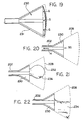
- an expandable sheath 230 is advanced through the interior of support conduit 202 about tissue containment bag 216 with expandable sheath 230 moving in the direction indicated by arrow F in Figure 15.
- Expandable sheath 230 has a pleated expandable portion 231, which is resilient and seeks to expand radially outwardly to relieve internal stresses such that upon expandable portion 231 reaching terminus 203 of support conduit 202 which is within sub-cutaneous tissue 226, expandable portion 231 expands radially into the configuration illustrated generally in Figure 16.
- Expandable portion 231 of sheath 230 is preferably pleated, as depicted in Figure 17.
- Expandable sheath 230 and particularly expandable portion 231 thereof provides support in the form of radially inwardly directed force on tissue containment bag 216 as bag 216 with target tissue mass 228 enveloped therein is pulled to the left in Figures 16, 19 and 20 as indicated generally by arrows G in Figure 19 and arrow H in Figure 20.
- tissue mass 228 reduces the transverse cross-sectional dimension of tissue mass 228 to at least the diameter of support conduit 202 as tissue containment bag 216 is drawn through the funnel-shaped expandable portion 231 of sheath 230 and into the interior of support conduit 202.
- expandable sheath 230 may be removed by pulling it in the direction indicated by arrow H in Figure 20.
- a medicament bag 232 may be inserted into the resected area through the interior of support conduit 202 and through expandable sheath 230, as indicated in Figure 21. This may provide means for supplying radioactive gas to provide radiation therapy to the resected area. Additionally, a radiographic marker depicted as 236 may be implanted into the resected area of interest, using the balloon or otherwise while expandable sheath 230 remains in the area of the resection.
- liquid medication indicated schematically as 234 in Figure 22 may be supplied to the resected area.
- expandable sheath maintaining the resected tissue in a spaced-apart condition facilitates application of the liquid medication to all parts of the resected volume.
- Support members 206 preferably have metallic tips to provide radiopaque characteristics as indicated by 230 in Figure 23 and may also have metallic or other radiopaque marker bands indicated as 240 in Figure 23.
- Central portions 242 of support members 206 are preferably radiolucent as indicated by the stippling in Figure 23.
Description
Claims (14)
- Apparatus (10, 200) for excision of a sub-cutaneous target tissue mass through a cutaneous incision smaller than maximum transverse dimension of the tissue mass excised, comprising:a. an axially elongated member (25, 202) including cutaneous tissue piercing means (65, 204) at one end;b. cutting means (50, 214) connected to said elongated member, the cutting means being adapted to electro-cauterize and being radially expandable relative to said elongated member for cutting a circumferential swath of dimension greater than maximum transverse dimension of said elongated member whereby said target tissue mass can be separated from surrounding tissue for excision thereof through said incision;
characterised in that the apparatus further comprisesc. flexible aseptic containment means (30, 216) adapted to be slidably advanced over and closed around said separated target tissue mass and subsequently to be withdrawn through said incision whereby said target tissue mass aseptically contained within said containment means can be withdrawn through said incision. - Apparatus as claimed in claim 1, characterised in that a drawstring (80, 218) is provided for drawing a distal margin (217) of the flexible aseptic containment means (30, 216) closed.
- Apparatus as claimed in claim 1 or 2, characterised in that an expandable sheath (230) is provided, the sheath being advanceable through the interior of the axially elongated member (202).
- Apparatus as claimed in claim 3, characterised in that the sheath (230) has a pleated expandable portion (231).
- Apparatus as claimed in any preceding claim, characterised in that the axially elongated member (202) includes axially elongated skin cutting means (204) insertable through the axially elongated member.
- Apparatus as claimed in any preceding claim, characterised in that an electrical power source (15) is provided for heating the cutting means (50, 214).
- Apparatus as claimed in any preceding claim, characterised in that the cutting means (214) comprises a tissue cutting wire loop.
- Apparatus as claimed in claim 7, characterised in that the cutting means (214) comprises a pair of tissue cutting wire loops.
- Apparatus as claimed in any one of claims 1 to 6, characterised in that a shaft (20) is provided for rotating the cutting means (50).
- Apparatus as claimed in claim 9, characterised in that the cutting means (50) is adapted to be rotated about an axis (12) of the shaft (20) after expansion into a circular array.
- Apparatus as claimed in claim 9 or 10, characterised in that the cutting means (50) is positioned between the piercing means (65) and an end of the rotatable shaft (20).
- Apparatus as claimed in any preceding claim, characterised in that the tissue piercing means (65) is provided with a dye port (70) for delivery of a marking fluid to subcutaneous areas.
- Apparatus as claimed in any preceding claim, characterised in that a plurality of support members (206) is insertable axially through the axially elongated member (202).
- Apparatus as claimed in claim 13, characterised in that the support members (206) are adapted to diverge radially from one another.
Applications Claiming Priority (3)
| Application Number | Priority Date | Filing Date | Title |
|---|---|---|---|
| US5366497P | 1997-07-24 | 1997-07-24 | |
| US53664P | 1997-07-24 | ||
| PCT/US1998/015160 WO1999004704A2 (en) | 1997-07-24 | 1998-07-23 | Breast surgery method and apparatus |
Publications (2)
| Publication Number | Publication Date |
|---|---|
| EP1003428A2 EP1003428A2 (en) | 2000-05-31 |
| EP1003428B1 true EP1003428B1 (en) | 2005-04-27 |
Family
ID=21985762
Family Applications (1)
| Application Number | Title | Priority Date | Filing Date |
|---|---|---|---|
| EP98935921A Expired - Lifetime EP1003428B1 (en) | 1997-07-24 | 1998-07-23 | Breast surgery apparatus |
Country Status (8)
| Country | Link |
|---|---|
| US (6) | US6280450B1 (en) |
| EP (1) | EP1003428B1 (en) |
| JP (1) | JP4255208B2 (en) |
| AU (1) | AU8507398A (en) |
| CA (1) | CA2297118C (en) |
| DE (1) | DE69829974T8 (en) |
| ES (1) | ES2242288T3 (en) |
| WO (1) | WO1999004704A2 (en) |
Families Citing this family (205)
| Publication number | Priority date | Publication date | Assignee | Title |
|---|---|---|---|---|
| US6350266B1 (en) * | 1995-02-02 | 2002-02-26 | Scimed Life Systems, Inc. | Hybrid stone retrieval device |
| US6626903B2 (en) * | 1997-07-24 | 2003-09-30 | Rex Medical, L.P. | Surgical biopsy device |
| JP4255208B2 (en) * | 1997-07-24 | 2009-04-15 | レックス メディカル リミテッド パートナーシップ | Device for resecting subcutaneous target tissue mass |
| US6270464B1 (en) | 1998-06-22 | 2001-08-07 | Artemis Medical, Inc. | Biopsy localization method and device |
| US20100030256A1 (en) | 1997-11-12 | 2010-02-04 | Genesis Technologies Llc | Medical Devices and Methods |
| US9498604B2 (en) | 1997-11-12 | 2016-11-22 | Genesis Technologies Llc | Medical device and method |
| US6530923B1 (en) | 1998-02-10 | 2003-03-11 | Artemis Medical, Inc. | Tissue removal methods and apparatus |
| WO1999023952A1 (en) * | 1997-11-12 | 1999-05-20 | William Dubrul | Biological passageway occlusion removal |
| US20040010206A1 (en) * | 1998-02-10 | 2004-01-15 | Dubrul William R. | Intraoperative tissue treatment methods |
| US6602204B2 (en) | 1998-02-10 | 2003-08-05 | Artemis Medical, Inc | Intraoperative tissue treatment methods |
| US6602265B2 (en) * | 1998-02-10 | 2003-08-05 | Artemis Medical, Inc. | Tissue separation medical device and method |
| JP2002502626A (en) * | 1998-02-10 | 2002-01-29 | アーテミス・メディカル・インコーポレイテッド | Supplementary device and method of using the same |
| EP1054635B1 (en) | 1998-02-10 | 2010-01-06 | Artemis Medical, Inc. | Occlusion, anchoring, tensioning or flow direction apparatus |
| US6331166B1 (en) * | 1998-03-03 | 2001-12-18 | Senorx, Inc. | Breast biopsy system and method |
| US6540693B2 (en) * | 1998-03-03 | 2003-04-01 | Senorx, Inc. | Methods and apparatus for securing medical instruments to desired locations in a patients body |
| US6659105B2 (en) | 1998-02-26 | 2003-12-09 | Senorx, Inc. | Tissue specimen isolating and damaging device and method |
| US6261241B1 (en) * | 1998-03-03 | 2001-07-17 | Senorx, Inc. | Electrosurgical biopsy device and method |
| US6344026B1 (en) | 1998-04-08 | 2002-02-05 | Senorx, Inc. | Tissue specimen encapsulation device and method thereof |
| US6454727B1 (en) * | 1998-03-03 | 2002-09-24 | Senorx, Inc. | Tissue acquisition system and method of use |
| US6997885B2 (en) * | 1998-04-08 | 2006-02-14 | Senorx, Inc. | Dilation devices and methods for removing tissue specimens |
| US20020058882A1 (en) * | 1998-06-22 | 2002-05-16 | Artemis Medical, Incorporated | Biopsy localization method and device |
| US6296639B1 (en) * | 1999-02-12 | 2001-10-02 | Novacept | Apparatuses and methods for interstitial tissue removal |
| US6179860B1 (en) | 1998-08-19 | 2001-01-30 | Artemis Medical, Inc. | Target tissue localization device and method |
| US7517348B2 (en) * | 1998-09-03 | 2009-04-14 | Rubicor Medical, Inc. | Devices and methods for performing procedures on a breast |
| US7329253B2 (en) * | 2003-12-09 | 2008-02-12 | Rubicor Medical, Inc. | Suction sleeve and interventional devices having such a suction sleeve |
| US6022362A (en) | 1998-09-03 | 2000-02-08 | Rubicor Medical, Inc. | Excisional biopsy devices and methods |
| US6936014B2 (en) * | 2002-10-16 | 2005-08-30 | Rubicor Medical, Inc. | Devices and methods for performing procedures on a breast |
| US6440147B1 (en) * | 1998-09-03 | 2002-08-27 | Rubicor Medical, Inc. | Excisional biopsy devices and methods |
| US8114006B2 (en) * | 1998-10-06 | 2012-02-14 | University Of South Florida | Radio guided seed localization of imaged lesions |
| US6496717B2 (en) * | 1998-10-06 | 2002-12-17 | University Of South Florida | Radio guided seed localization of imaged lesions |
| US6036698A (en) | 1998-10-30 | 2000-03-14 | Vivant Medical, Inc. | Expandable ring percutaneous tissue removal device |
| WO2000067825A1 (en) * | 1999-05-07 | 2000-11-16 | Microheart, Inc. | Apparatus and method for delivering therapeutic and diagnostic agents |
| EP1191876A4 (en) * | 1999-06-04 | 2007-03-21 | Artemis Medical Inc | Tissue removal methods and apparatus |
| US6306132B1 (en) | 1999-06-17 | 2001-10-23 | Vivant Medical | Modular biopsy and microwave ablation needle delivery apparatus adapted to in situ assembly and method of use |
| US6514248B1 (en) | 1999-10-15 | 2003-02-04 | Neothermia Corporation | Accurate cutting about and into tissue volumes with electrosurgically deployed electrodes |
| ITCE990004A1 (en) * | 1999-10-25 | 2000-01-25 | Mario Immacolato Paternuosto | VALVE FOR BIOPSY FORCEPS IN DIGESTIVE ENDOSCOPY |
| SE9904223D0 (en) * | 1999-11-19 | 1999-11-19 | Safe Conduct Ab | Working Device |
| US6277083B1 (en) | 1999-12-27 | 2001-08-21 | Neothermia Corporation | Minimally invasive intact recovery of tissue |
| EP1253859B1 (en) * | 2000-01-04 | 2009-04-15 | Medtronic Vascular, Inc. | Apparatus for creating a channel between adjacent body lumens |
| WO2001060235A2 (en) | 2000-02-18 | 2001-08-23 | Fogarty Thomas J M D | Improved device for accurately marking tissue |
| US6722371B1 (en) | 2000-02-18 | 2004-04-20 | Thomas J. Fogarty | Device for accurately marking tissue |
| US6564806B1 (en) | 2000-02-18 | 2003-05-20 | Thomas J. Fogarty | Device for accurately marking tissue |
| ATE318559T1 (en) * | 2000-04-05 | 2006-03-15 | Kyphon Inc | DEVICES FOR TREATING BROKEN AND/OR DISEASE BONES |
| US20030204188A1 (en) * | 2001-11-07 | 2003-10-30 | Artemis Medical, Inc. | Tissue separating and localizing catheter assembly |
| US7534242B2 (en) * | 2003-02-25 | 2009-05-19 | Artemis Medical, Inc. | Tissue separating catheter assembly and method |
| US6994677B1 (en) | 2003-02-25 | 2006-02-07 | Artemis Medical, Inc. | Tissue localizing and separating assembly |
| US20060025781A1 (en) * | 2001-01-17 | 2006-02-02 | Young Wayne P | Laparoscopic instruments and methods utilizing suction |
| US6958069B2 (en) * | 2001-01-17 | 2005-10-25 | Mark LoGuidice | Instruments and methods for use in laparoscopic surgery |
| US6743228B2 (en) | 2001-09-12 | 2004-06-01 | Manoa Medical, Inc. | Devices and methods for tissue severing and removal |
| US6878147B2 (en) | 2001-11-02 | 2005-04-12 | Vivant Medical, Inc. | High-strength microwave antenna assemblies |
| US7197363B2 (en) | 2002-04-16 | 2007-03-27 | Vivant Medical, Inc. | Microwave antenna having a curved configuration |
| US6752767B2 (en) | 2002-04-16 | 2004-06-22 | Vivant Medical, Inc. | Localization element with energized tip |
| US20030225432A1 (en) * | 2002-05-31 | 2003-12-04 | Baptiste Reginald C. | Soft tissue retraction device for an endoscopic instrument |
| US6840948B2 (en) | 2002-06-06 | 2005-01-11 | Ethicon-Endo Surgery, Inc. | Device for removal of tissue lesions |
| US6855140B2 (en) | 2002-06-06 | 2005-02-15 | Thomas E. Albrecht | Method of tissue lesion removal |
| US7044956B2 (en) * | 2002-07-03 | 2006-05-16 | Rubicor Medical, Inc. | Methods and devices for cutting and collecting soft tissue |
| US20040006355A1 (en) * | 2002-07-03 | 2004-01-08 | Rubicor Medical, Inc. | Methods and devices for cutting and collecting soft tissue |
| AU2003254224A1 (en) * | 2002-07-26 | 2004-02-16 | Stuart B. Brown | Tissue and fluid sampling device |
| US7029451B2 (en) | 2002-11-06 | 2006-04-18 | Rubicor Medical, Inc. | Excisional devices having selective cutting and atraumatic configurations and methods of using same |
| US20040116828A1 (en) * | 2002-11-07 | 2004-06-17 | White Keith M. | Biological specimen collector and container with stand |
| US6847848B2 (en) * | 2003-01-07 | 2005-01-25 | Mmtc, Inc | Inflatable balloon catheter structural designs and methods for treating diseased tissue of a patient |
| CA2519445C (en) * | 2003-03-17 | 2012-06-12 | Tyco Healthcare Group, Lp | Endoscopic tissue removal apparatus and method |
| US7122011B2 (en) * | 2003-06-18 | 2006-10-17 | Rubicor Medical, Inc. | Methods and devices for cutting and collecting soft tissue |
| DE10328329A1 (en) * | 2003-06-24 | 2005-01-27 | Fraunhofer-Gesellschaft zur Förderung der angewandten Forschung e.V. | Surgical device in particular to be used for removal of lung tissue, comprising loop-shaped electrodes and receptacle |
| US8308682B2 (en) | 2003-07-18 | 2012-11-13 | Broncus Medical Inc. | Devices for maintaining patency of surgically created channels in tissue |
| US7311703B2 (en) | 2003-07-18 | 2007-12-25 | Vivant Medical, Inc. | Devices and methods for cooling microwave antennas |
| US7588545B2 (en) | 2003-09-10 | 2009-09-15 | Boston Scientific Scimed, Inc. | Forceps and collection assembly with accompanying mechanisms and related methods of use |
| US7942896B2 (en) | 2003-11-25 | 2011-05-17 | Scimed Life Systems, Inc. | Forceps and collection assembly and related methods of use and manufacture |
| US7951073B2 (en) * | 2004-01-21 | 2011-05-31 | Boston Scientific Limited | Endoscopic device having spray mechanism and related methods of use |
| US8409167B2 (en) | 2004-07-19 | 2013-04-02 | Broncus Medical Inc | Devices for delivering substances through an extra-anatomic opening created in an airway |
| WO2006015354A2 (en) * | 2004-07-30 | 2006-02-09 | Washington University In St. Louis | Electrosurgical systems and methods |
| JP2006075232A (en) * | 2004-09-07 | 2006-03-23 | Terumo Corp | Wire for removing endovascular foreign body, and medical appliance |
| JP2006075233A (en) | 2004-09-07 | 2006-03-23 | Terumo Corp | Wire for removing endovascular foreign body, and medical appliance |
| US8078266B2 (en) | 2005-10-25 | 2011-12-13 | Voyage Medical, Inc. | Flow reduction hood systems |
| US10064540B2 (en) | 2005-02-02 | 2018-09-04 | Intuitive Surgical Operations, Inc. | Visualization apparatus for transseptal access |
| US20080015569A1 (en) | 2005-02-02 | 2008-01-17 | Voyage Medical, Inc. | Methods and apparatus for treatment of atrial fibrillation |
| US8934962B2 (en) | 2005-02-02 | 2015-01-13 | Intuitive Surgical Operations, Inc. | Electrophysiology mapping and visualization system |
| US11478152B2 (en) | 2005-02-02 | 2022-10-25 | Intuitive Surgical Operations, Inc. | Electrophysiology mapping and visualization system |
| US8137333B2 (en) | 2005-10-25 | 2012-03-20 | Voyage Medical, Inc. | Delivery of biological compounds to ischemic and/or infarcted tissue |
| US9510732B2 (en) | 2005-10-25 | 2016-12-06 | Intuitive Surgical Operations, Inc. | Methods and apparatus for efficient purging |
| US7942873B2 (en) * | 2005-03-25 | 2011-05-17 | Angiodynamics, Inc. | Cavity ablation apparatus and method |
| US7762960B2 (en) | 2005-05-13 | 2010-07-27 | Boston Scientific Scimed, Inc. | Biopsy forceps assemblies |
| US20070149990A1 (en) * | 2005-07-11 | 2007-06-28 | Palmer Erika I | Apparatus and methods of tissue removal within a spine |
| US9320540B2 (en) | 2005-09-02 | 2016-04-26 | Madison Surgical Designs, Llc | Surgical devices and related methods thereof |
| US8221310B2 (en) * | 2005-10-25 | 2012-07-17 | Voyage Medical, Inc. | Tissue visualization device and method variations |
| US20070142852A1 (en) * | 2005-12-21 | 2007-06-21 | Manoa Medical, Inc., A Delaware Corporation | Tissue cutting device |
| US7569053B2 (en) * | 2006-03-03 | 2009-08-04 | Intact Medical Corporation | Apparatus for retrieving a tissue volume with improved positioning precursor assembly |
| US9055906B2 (en) | 2006-06-14 | 2015-06-16 | Intuitive Surgical Operations, Inc. | In-vivo visualization systems |
| US10004388B2 (en) | 2006-09-01 | 2018-06-26 | Intuitive Surgical Operations, Inc. | Coronary sinus cannulation |
| US20080097476A1 (en) | 2006-09-01 | 2008-04-24 | Voyage Medical, Inc. | Precision control systems for tissue visualization and manipulation assemblies |
| US8068921B2 (en) | 2006-09-29 | 2011-11-29 | Vivant Medical, Inc. | Microwave antenna assembly and method of using the same |
| US20080103412A1 (en) * | 2006-11-01 | 2008-05-01 | Yem Chin | Removing Tissue |
| US8758229B2 (en) | 2006-12-21 | 2014-06-24 | Intuitive Surgical Operations, Inc. | Axial visualization systems |
| US20080221587A1 (en) * | 2007-03-09 | 2008-09-11 | Jeremy Schwartz | Two-stage snare-basket medical device |
| AT505002B1 (en) * | 2007-04-23 | 2008-10-15 | Ami Gmbh | DEVICE FOR USE IN THE TREATMENT OF A HEMORRHOIDENEPROLAP |
| US8657805B2 (en) | 2007-05-08 | 2014-02-25 | Intuitive Surgical Operations, Inc. | Complex shape steerable tissue visualization and manipulation catheter |
| US8162961B2 (en) | 2007-07-23 | 2012-04-24 | Zimmer Orthobiologies, Inc. | Medical devices and methods for cutting and suturing biological tissue |
| US9622813B2 (en) | 2007-11-01 | 2017-04-18 | Covidien Lp | Method for volume determination and geometric reconstruction |
| US8292880B2 (en) | 2007-11-27 | 2012-10-23 | Vivant Medical, Inc. | Targeted cooling of deployable microwave antenna |
| US20090171293A1 (en) * | 2007-12-28 | 2009-07-02 | Wilson-Cook Medical Inc. | Self expanding wire guide |
| US8435237B2 (en) | 2008-01-29 | 2013-05-07 | Covidien Lp | Polyp encapsulation system and method |
| US20090270892A1 (en) * | 2008-04-25 | 2009-10-29 | Greg Arcenio | Steerable medical device for tissue disruption |
| US20090270893A1 (en) * | 2008-04-25 | 2009-10-29 | Greg Arcenio | Medical device for tissue disruption with serrated expandable portion |
| US20090270862A1 (en) * | 2008-04-25 | 2009-10-29 | Greg Arcenio | Medical device with one-way rotary drive mechanism |
| US9370341B2 (en) | 2008-10-23 | 2016-06-21 | Covidien Lp | Surgical retrieval apparatus |
| US20100106052A1 (en) * | 2008-10-23 | 2010-04-29 | Margaret Uznanski | Surgical retractor |
| US8298157B2 (en) * | 2009-12-15 | 2012-10-30 | C. R. Bard, Inc. | Introducer cannula having a tissue anchor for use with a medical instrument |
| US9113848B2 (en) * | 2010-02-03 | 2015-08-25 | Covidien Lp | Surgical retrieval apparatus |
| US8585712B2 (en) | 2010-02-03 | 2013-11-19 | Covidien Lp | Surgical retrieval apparatus |
| US20110190781A1 (en) * | 2010-02-03 | 2011-08-04 | Nicholas John Collier | Surgical retrieval apparatus |
| GB2478127A (en) * | 2010-02-25 | 2011-08-31 | Fouad Mounir Elias Kaldas | Tumour encapsulation device |
| US8728067B2 (en) | 2010-03-08 | 2014-05-20 | Covidien Lp | Microwave antenna probe having a deployable ground plane |
| EP2552322B1 (en) | 2010-03-30 | 2016-11-16 | Martin L. Flatland | Tissue excision device |
| US9561094B2 (en) | 2010-07-23 | 2017-02-07 | Nfinium Vascular Technologies, Llc | Devices and methods for treating venous diseases |
| WO2012043081A1 (en) * | 2010-09-27 | 2012-04-05 | テルモ株式会社 | Medical device |
| US9005215B2 (en) | 2010-10-04 | 2015-04-14 | Covidien Lp | Specimen retrieval apparatus |
| US8777961B2 (en) | 2010-10-04 | 2014-07-15 | Covidien Lp | Surgical retrieval apparatus |
| US8579914B2 (en) | 2010-12-17 | 2013-11-12 | Covidien Lp | Specimen retrieval device |
| US8734464B2 (en) | 2011-01-06 | 2014-05-27 | Covidien Lp | Surgical retrieval apparatus for thoracic procedures |
| US8795291B2 (en) | 2011-04-29 | 2014-08-05 | Covidien Lp | Specimen retrieval device |
| JP2014521381A (en) * | 2011-05-13 | 2014-08-28 | ブロンカス テクノロジーズ, インコーポレイテッド | Methods and devices for tissue ablation |
| US8709034B2 (en) | 2011-05-13 | 2014-04-29 | Broncus Medical Inc. | Methods and devices for diagnosing, monitoring, or treating medical conditions through an opening through an airway wall |
| US9204896B2 (en) * | 2011-07-14 | 2015-12-08 | Alphatec Spine, Inc. | Instrument for removal of material from within a body |
| US10010437B2 (en) | 2011-10-17 | 2018-07-03 | W. L. Gore & Associates, Inc. | Endoluminal device retrieval devices and related systems and methods |
| US8968329B2 (en) | 2011-10-19 | 2015-03-03 | Covidien Lp | Surgical retrieval apparatus for thoracic procedures |
| US9993229B2 (en) | 2011-11-08 | 2018-06-12 | Covidien Lp | Specimen retrieval device |
| US8906036B2 (en) | 2011-11-21 | 2014-12-09 | Covidien Lp | Surgical retrieval apparatus |
| WO2013078235A1 (en) | 2011-11-23 | 2013-05-30 | Broncus Medical Inc | Methods and devices for diagnosing, monitoring, or treating medical conditions through an opening through an airway wall |
| US9788820B2 (en) * | 2011-12-15 | 2017-10-17 | Femasys Inc | Methods and devices for cervical cell and tissue sampling |
| US9549747B2 (en) | 2012-01-23 | 2017-01-24 | Covidien Lp | Reusable surgical retrieval apparatus with disposable cartridge assembly |
| WO2013168166A1 (en) * | 2012-05-10 | 2013-11-14 | Arch Medical Devices Ltd. | Biopsy needle with a laterally expandable distal portion |
| US9693790B2 (en) * | 2012-08-02 | 2017-07-04 | Covidien Lp | Laparoscopic gallbladder extraction device |
| US9061249B2 (en) * | 2012-08-24 | 2015-06-23 | The Boeing Company | Aircraft fuel tank flammability reduction method and system |
| US10000294B2 (en) | 2012-08-24 | 2018-06-19 | The Boeing Company | Aircraft fuel tank flammability reduction method and system |
| US9327243B2 (en) | 2012-08-24 | 2016-05-03 | The Boeing Company | Aircraft fuel tank flammability reduction methods and systems |
| US9259211B2 (en) | 2012-12-24 | 2016-02-16 | Transmed7, Llc | Automated, selectable, soft tissue excision biopsy devices and methods |
| WO2014134285A1 (en) | 2013-03-01 | 2014-09-04 | Covidien Lp | Specimen retrieval device with pouch stop |
| US20140309524A1 (en) | 2013-04-16 | 2014-10-16 | Transmed7, Llc | Methods, devices and therapeutic platform for automated, selectable, soft tissue resection |
| CA2911243C (en) * | 2013-05-03 | 2020-06-30 | Femasys Inc. | Methods and devices for endometrial cell and tissue sampling |
| US9592067B2 (en) | 2013-06-14 | 2017-03-14 | Covidien Lp | Specimen retrieval device including a reusable shaft with interchangeable pouch |
| US9987031B2 (en) | 2013-06-14 | 2018-06-05 | Covidien Lp | Specimen retrieval device including an integrated sliding grasper |
| CA2921042A1 (en) | 2013-08-23 | 2015-02-26 | Covidien Lp | Specimen retrieval device |
| CA2927436C (en) | 2013-10-15 | 2022-04-26 | Stryker Corporation | Device for creating a void space in living tissue, the device including a handle with a control knob that can be set regardless of the orientation of the handle |
| JP6352642B2 (en) * | 2013-12-03 | 2018-07-04 | 川澄化学工業株式会社 | Intravascular foreign body removal catheter |
| AT515317B1 (en) * | 2014-02-05 | 2015-08-15 | Tosun Kadir Dr | Endoscopic cutting device |
| US20160324515A1 (en) * | 2014-03-07 | 2016-11-10 | Beacon Surgical Instruments, Llc | Single incision specimen retrieval assembly, method of use and kit |
| US20150351775A1 (en) | 2014-06-04 | 2015-12-10 | Nfinium Vascular Technologies, Llc | Low radial force vascular device and method of occlusion |
| KR20240013275A (en) | 2014-07-22 | 2024-01-30 | 엑시미스 서지컬 인코포레이티드 | Large volume tissue reduction and removal system and method |
| US20170245839A1 (en) * | 2014-08-19 | 2017-08-31 | Covidien Lp | Specimen retrieval systems |
| US20170281212A1 (en) * | 2014-09-02 | 2017-10-05 | Mayo Foundation For Medical Education And Research | Methods and devices for localizing, delineating and anchoring liver lesions for resection |
| WO2016168865A1 (en) * | 2015-03-06 | 2016-10-20 | Beacon Surgial, Llc | Surgical instrument including side-activation mechanism, layered specimen retrieval gag, method of use and kit |
| EP3349677A1 (en) | 2015-09-17 | 2018-07-25 | Eximis Surgical LLC | Electrosurgical device and methods |
| US11937848B2 (en) | 2016-06-10 | 2024-03-26 | University Of Virginia Patent Foundation | Port apparatus and sheath device for electrocautery and related methods thereof |
| CA3045942A1 (en) * | 2016-11-11 | 2018-05-17 | Bernd Buscherhoff | Device for removing organs from a human or animal body |
| US10675058B2 (en) | 2017-01-19 | 2020-06-09 | Covidien Lp | Devices, systems, and methods for large tissue specimen removal |
| US10716594B2 (en) * | 2017-06-12 | 2020-07-21 | Covidien Lp | Devices, systems, and methods for tissue specimen removal |
| US10653400B2 (en) | 2017-08-07 | 2020-05-19 | Covidien Lp | Specimen retrieval device |
| US11083490B2 (en) | 2017-09-21 | 2021-08-10 | Covidien Lp | Systems and methods for large tissue specimen removal |
| US11065051B2 (en) | 2017-11-03 | 2021-07-20 | Covidien Lp | Specimen retrieval device |
| US10973543B2 (en) | 2018-01-10 | 2021-04-13 | Covidien Lp | Dual wall tissue extraction bag |
| US10874386B2 (en) | 2018-01-24 | 2020-12-29 | Covidien Lp | Specimen retrieval device |
| US11730459B2 (en) | 2018-02-22 | 2023-08-22 | Covidien Lp | Specimen retrieval devices and methods |
| US10792057B2 (en) | 2018-03-23 | 2020-10-06 | Covidien Lp | Articulation mechanisms for tissue specimen retrieval devices and tissue specimen retrieval devices incorporating the same |
| US11318010B1 (en) | 2018-04-02 | 2022-05-03 | Lifei Guo | Tissue removing |
| US11083443B2 (en) | 2018-04-24 | 2021-08-10 | Covidien Lp | Specimen retrieval device |
| US10667800B2 (en) | 2018-05-08 | 2020-06-02 | Covidien Lp | Four bar articulation mechanism for tissue specimen retrieval device |
| US11045176B2 (en) | 2018-05-18 | 2021-06-29 | Covidien Lp | Specimen retrieval device |
| US10792023B2 (en) | 2018-06-06 | 2020-10-06 | Covidien Lp | Shaft driven mechanism for articulating tissue specimen retrieval device |
| US11134932B2 (en) | 2018-08-13 | 2021-10-05 | Covidien Lp | Specimen retrieval device |
| US11730480B2 (en) | 2018-09-14 | 2023-08-22 | Covidien Lp | Method and apparatus for accessing matter disposed within an internal body vessel |
| US11191559B2 (en) | 2018-09-19 | 2021-12-07 | Covidien Lp | Specimen retrieval device |
| US10912545B2 (en) | 2019-02-04 | 2021-02-09 | Covidien Lp | Tissue specimen retrieval devices and methods |
| US11344300B2 (en) | 2019-03-26 | 2022-05-31 | Covidien Lp | Specimen capture stapler |
| US11172915B2 (en) | 2019-04-24 | 2021-11-16 | Covidien Lp | Specimen retrieval devices with selective bag release |
| WO2020219392A2 (en) | 2019-04-24 | 2020-10-29 | Stryker Corporation | Systems and methods for off-axis augmentation of a vertebral body |
| US11064984B2 (en) | 2019-05-07 | 2021-07-20 | Covidien Lp | Specimen containment device |
| US11246578B2 (en) | 2019-05-15 | 2022-02-15 | Covidien Lp | Tissue collection bags with inner surface pouches |
| US11051834B2 (en) | 2019-05-17 | 2021-07-06 | Covidien Lp | Tissue specimen retrieval device |
| CZ2019310A3 (en) * | 2019-05-20 | 2020-12-16 | Jiří Votruba | Equipment for collecting lung tissue in an endoscopic lung examination |
| US11426203B2 (en) | 2019-05-23 | 2022-08-30 | Covidien Lp | Tissue guards and systems incorporating the same for tissue specimen removal procedures and other surgical procedures |
| US11426151B2 (en) | 2019-06-04 | 2022-08-30 | Covidien Lp | Bag closure for specimen retrieval device |
| US11051795B2 (en) | 2019-07-31 | 2021-07-06 | Covidien Lp | Tissue retrieval bag |
| US11304687B2 (en) | 2019-08-13 | 2022-04-19 | Covidien Lp | Tissue specimen bag furling device and method |
| US11253240B2 (en) | 2019-09-10 | 2022-02-22 | Covidien Lp | Tissue specimen retrieval devices |
| US11172949B2 (en) | 2019-10-07 | 2021-11-16 | Covidien Lp | Tissue specimen retrieval devices |
| US11446015B2 (en) | 2019-10-30 | 2022-09-20 | Covidien Lp | Specimen retrieval bag |
| US11707264B2 (en) | 2020-01-30 | 2023-07-25 | Covidien Lp | Rollable tissue specimen bag with improved brim for tenting |
| US11759188B2 (en) | 2020-01-31 | 2023-09-19 | Covidien Lp | Devices, systems, and methods for specimen removal |
| US11344284B2 (en) | 2020-02-11 | 2022-05-31 | Covidien Lp | Tissue specimen retrieval device with variable bag brim |
| US11160543B2 (en) | 2020-02-13 | 2021-11-02 | Covidien Lp | Magnetic suture tab for free standing specimen bag |
| US11224413B2 (en) | 2020-02-19 | 2022-01-18 | Covidien Lp | Retrieval device with bag release mechanism |
| JP7370283B2 (en) | 2020-03-10 | 2023-10-27 | テルモ株式会社 | Administration device and method |
| US11369352B2 (en) | 2020-03-31 | 2022-06-28 | Covidien Lp | Dual channel design for free standing specimen bag |
| US11406369B2 (en) | 2020-04-08 | 2022-08-09 | Covidien Lp | Tissue specimen retrieval device with reinforced spring |
| KR102416005B1 (en) | 2020-04-29 | 2022-06-30 | 연세대학교 산학협력단 | Apparatus and Method for Cutting and Retrieving Breast Specimen |
| US11246613B2 (en) | 2020-05-15 | 2022-02-15 | Covidien Lp | Actuation mechanisms for tissue specimen retrieval devices and tissue specimen retrieval devices incorporating the same |
| US11304714B2 (en) | 2020-05-19 | 2022-04-19 | Covidien Lp | Tissue specimen retrieval device with assisted deployment |
| US11627987B2 (en) | 2020-05-20 | 2023-04-18 | Covidien Lp | Low impact cutting guard |
| US11510749B2 (en) | 2020-05-26 | 2022-11-29 | Covidien Lp | Insertable cutting guard |
| US11517297B2 (en) | 2020-06-05 | 2022-12-06 | Covidien Lp | Rollable tissue specimen bag with improved brim for tenting |
| US11931067B2 (en) | 2020-08-15 | 2024-03-19 | Covidien Lp | Insertable cutting guards |
| DE102020124917A1 (en) | 2020-09-24 | 2022-03-24 | Frank Schure | Medical instrument for minimally invasive removal of biological material from a human or animal body |
| CN113017776B (en) * | 2020-12-24 | 2022-05-17 | 中国人民解放军总医院第三医学中心 | Superficial tumor closed resection device and use method thereof |
| WO2023158841A1 (en) * | 2022-02-18 | 2023-08-24 | Incite Medical Sarl | Open loop écraseur for tenotomy |
| KR20230137592A (en) | 2022-03-22 | 2023-10-05 | 연세대학교 산학협력단 | Device for cutting specimen |
Family Cites Families (87)
| Publication number | Priority date | Publication date | Assignee | Title |
|---|---|---|---|---|
| US533804A (en) * | 1895-02-05 | Nicholas j | ||
| US2816552A (en) * | 1954-06-29 | 1957-12-17 | Roy D Hoffman | Teat bistoury with improved cutter blade adjusting means |
| US3320957A (en) * | 1964-05-21 | 1967-05-23 | Sokolik Edward | Surgical instrument |
| DE2513868C2 (en) * | 1974-04-01 | 1982-11-04 | Olympus Optical Co., Ltd., Tokyo | Bipolar electrodiathermy forceps |
| DE3247793C2 (en) | 1981-12-31 | 1986-01-09 | Harald 7200 Tuttlingen Maslanka | High frequency surgical loop electrode |
| US4611594A (en) | 1984-04-11 | 1986-09-16 | Northwestern University | Medical instrument for containment and removal of calculi |
| US4616656A (en) | 1985-03-19 | 1986-10-14 | Nicholson James E | Self-actuating breast lesion probe and method of using |
| GB8729648D0 (en) | 1987-12-19 | 1988-02-03 | Coats Viyella Medical Ltd | Biopsy needle |
| US5556376A (en) | 1988-07-22 | 1996-09-17 | Yoon; Inbae | Multifunctional devices having loop configured portions and collection systems for endoscopic surgical procedures and methods thereof |
| US5904679A (en) | 1989-01-18 | 1999-05-18 | Applied Medical Resources Corporation | Catheter with electrosurgical cutter |
| US4966604A (en) | 1989-01-23 | 1990-10-30 | Interventional Technologies Inc. | Expandable atherectomy cutter with flexibly bowed blades |
| US4976711A (en) | 1989-04-13 | 1990-12-11 | Everest Medical Corporation | Ablation catheter with selectively deployable electrodes |
| SU1683701A1 (en) * | 1989-07-14 | 1991-10-15 | Новосибирский медицинский институт | Device for extraction of foreign bodies from tubular organs |
| US5632746A (en) | 1989-08-16 | 1997-05-27 | Medtronic, Inc. | Device or apparatus for manipulating matter |
| US5282484A (en) * | 1989-08-18 | 1994-02-01 | Endovascular Instruments, Inc. | Method for performing a partial atherectomy |
| US4935027A (en) * | 1989-08-21 | 1990-06-19 | Inbae Yoon | Surgical suture instrument with remotely controllable suture material advancement |
| US4997435A (en) * | 1989-09-25 | 1991-03-05 | Methodist Hospital Of Indiana Inc. | Percutaneous catheter with encapsulating receptacle |
| US5514153A (en) * | 1990-03-02 | 1996-05-07 | General Surgical Innovations, Inc. | Method of dissecting tissue layers |
| US5078716A (en) * | 1990-05-11 | 1992-01-07 | Doll Larry F | Electrosurgical apparatus for resecting abnormal protruding growth |
| US5201741A (en) | 1990-07-24 | 1993-04-13 | Andrew Surgical, Inc. | Surgical snare with shape memory effect wire |
| US5100423A (en) | 1990-08-21 | 1992-03-31 | Medical Engineering & Development Institute, Inc. | Ablation catheter |
| US5353804A (en) * | 1990-09-18 | 1994-10-11 | Peb Biopsy Corporation | Method and device for percutaneous exisional breast biopsy |
| JP3256540B2 (en) | 1990-10-09 | 2002-02-12 | メッドトロニック・インコーポレイテッド | Device or device for manipulating the target object |
| US5190561A (en) * | 1991-01-23 | 1993-03-02 | Surgical Innovations, Inc. | Tissue and organ extractor |
| US5370647A (en) | 1991-01-23 | 1994-12-06 | Surgical Innovations, Inc. | Tissue and organ extractor |
| US5176128A (en) | 1991-01-24 | 1993-01-05 | Andrese Craig A | Organ retractor |
| US5176687A (en) * | 1991-05-10 | 1993-01-05 | Hasson Harrith M | Disposable pouch container for isolation and retrieval of tissues removed at laparoscopy |
| US5207675A (en) * | 1991-07-15 | 1993-05-04 | Jerome Canady | Surgical coagulation device |
| US5197968A (en) | 1991-08-14 | 1993-03-30 | Mectra Labs, Inc. | Disposable tissue retrieval assembly |
| US5759187A (en) | 1991-11-05 | 1998-06-02 | Wilk & Nakao Medical Technology, Incorporated | Surgical retrieval assembly and associated method |
| US5281238A (en) * | 1991-11-22 | 1994-01-25 | Chin Albert K | Endoscopic ligation instrument |
| US5524633A (en) | 1991-11-25 | 1996-06-11 | Advanced Surgical, Inc. | Self-deploying isolation bag |
| FR2685190B1 (en) * | 1991-12-23 | 1998-08-07 | Jean Marie Lefebvre | ROTARY ATHERECTOMY OR THROMBECTOMY DEVICE WITH CENTRIFUGAL TRANSVERSE DEVELOPMENT. |
| AU682003B2 (en) | 1992-06-26 | 1997-09-18 | Schneider (Usa) Inc. | Catheter with expandable wire mesh tip |
| US5224488A (en) * | 1992-08-31 | 1993-07-06 | Neuffer Francis H | Biopsy needle with extendable cutting means |
| US5318576A (en) * | 1992-12-16 | 1994-06-07 | Plassche Jr Walter M | Endovascular surgery systems |
| DE69433774T2 (en) | 1993-02-19 | 2005-04-14 | Boston Scientific Corp., Natick | SURGICAL EXTRACTOR |
| US5897567A (en) | 1993-04-29 | 1999-04-27 | Scimed Life Systems, Inc. | Expandable intravascular occlusion material removal devices and methods of use |
| US5417697A (en) * | 1993-07-07 | 1995-05-23 | Wilk; Peter J. | Polyp retrieval assembly with cauterization loop and suction web |
| GB9314640D0 (en) | 1993-07-15 | 1993-08-25 | Salim Aws S M | Tunnellimg catheter |
| US5573008A (en) | 1993-10-29 | 1996-11-12 | Boston Scientific Corporation | Multiple biopsy sampling coring device |
| US5439474A (en) | 1993-10-08 | 1995-08-08 | Li Medical Technologies, Inc. | Morcellator system |
| US5437665A (en) * | 1993-10-12 | 1995-08-01 | Munro; Malcolm G. | Electrosurgical loop electrode instrument for laparoscopic surgery |
| US5397320A (en) * | 1994-03-03 | 1995-03-14 | Essig; Mitchell N. | Dissecting surgical device and associated method |
| US6216043B1 (en) | 1994-03-04 | 2001-04-10 | Ep Technologies, Inc. | Asymmetric multiple electrode support structures |
| US5649547A (en) | 1994-03-24 | 1997-07-22 | Biopsys Medical, Inc. | Methods and devices for automated biopsy and collection of soft tissue |
| US5746747A (en) * | 1994-05-13 | 1998-05-05 | Mckeating; John A. | Polypectomy instrument |
| US5794626A (en) | 1994-08-18 | 1998-08-18 | Kieturakis; Maciej J. | Excisional stereotactic apparatus |
| RU2082230C1 (en) | 1994-10-05 | 1997-06-20 | Опытное конструкторское бюро машиностроения | Cap of nuclear reactor |
| US5885278A (en) | 1994-10-07 | 1999-03-23 | E.P. Technologies, Inc. | Structures for deploying movable electrode elements |
| US6059734A (en) | 1995-01-06 | 2000-05-09 | Yoon; Inbae | Methods of collecting tissue at obstructed anatomical sites |
| US5947964A (en) | 1995-03-03 | 1999-09-07 | Neothermia Corporation | Methods and apparatus for therapeutic cauterization of predetermined volumes of biological tissue |
| US6312428B1 (en) | 1995-03-03 | 2001-11-06 | Neothermia Corporation | Methods and apparatus for therapeutic cauterization of predetermined volumes of biological tissue |
| US6106524A (en) | 1995-03-03 | 2000-08-22 | Neothermia Corporation | Methods and apparatus for therapeutic cauterization of predetermined volumes of biological tissue |
| US5795308A (en) | 1995-03-09 | 1998-08-18 | Russin; Lincoln D. | Apparatus for coaxial breast biopsy |
| US5846248A (en) * | 1995-04-13 | 1998-12-08 | Boston Scientific Corporation | Method and apparatus for severing and capturing polyps |
| DE19515280C2 (en) | 1995-04-26 | 1997-06-12 | Siegfried Riek | Device for removing tissue or the like from the abdominal cavity |
| US5853374A (en) * | 1995-10-11 | 1998-12-29 | Applied Medical Resources Corporation | Tissue collection and retrieval bag |
| US5782775A (en) | 1995-10-20 | 1998-07-21 | United States Surgical Corporation | Apparatus and method for localizing and removing tissue |
| US5709697A (en) | 1995-11-22 | 1998-01-20 | United States Surgical Corporation | Apparatus and method for removing tissue |
| US5895417A (en) | 1996-03-06 | 1999-04-20 | Cardiac Pathways Corporation | Deflectable loop design for a linear lesion ablation apparatus |
| US6096053A (en) | 1996-05-03 | 2000-08-01 | Scimed Life Systems, Inc. | Medical retrieval basket |
| US5735289A (en) | 1996-08-08 | 1998-04-07 | Pfeffer; Herbert G. | Method and apparatus for organic specimen retrieval |
| US5820629A (en) | 1996-08-13 | 1998-10-13 | Medtronic, Inc. | Intimal lining transition device and endarterectomy method |
| US5810806A (en) | 1996-08-29 | 1998-09-22 | Ethicon Endo-Surgery | Methods and devices for collection of soft tissue |
| US5895361A (en) | 1997-02-14 | 1999-04-20 | Symbiosis Corporation | Esophageal biopsy jaw assembly and endoscopic instrument incorporating the same |
| JP3909718B2 (en) | 1997-02-24 | 2007-04-25 | クック ウロロジカル インク. | Medical device having a tipless basket |
| US5871454A (en) | 1997-04-22 | 1999-02-16 | Majlessi; Heshmat | Percutaneous excisional biopsy device |
| JP4255208B2 (en) * | 1997-07-24 | 2009-04-15 | レックス メディカル リミテッド パートナーシップ | Device for resecting subcutaneous target tissue mass |
| US6626903B2 (en) * | 1997-07-24 | 2003-09-30 | Rex Medical, L.P. | Surgical biopsy device |
| US6080113A (en) | 1998-09-11 | 2000-06-27 | Imagyn Medical Technologies California, Inc. | Incisional breast biopsy device |
| US6530923B1 (en) | 1998-02-10 | 2003-03-11 | Artemis Medical, Inc. | Tissue removal methods and apparatus |
| US6007495A (en) | 1998-01-22 | 1999-12-28 | United States Surgical Corporation | Biopsy apparatus and method |
| JP2002502626A (en) | 1998-02-10 | 2002-01-29 | アーテミス・メディカル・インコーポレイテッド | Supplementary device and method of using the same |
| JP4157183B2 (en) | 1998-02-17 | 2008-09-24 | オリンパス株式会社 | Endoscopic treatment tool |
| US6331166B1 (en) | 1998-03-03 | 2001-12-18 | Senorx, Inc. | Breast biopsy system and method |
| US6261241B1 (en) | 1998-03-03 | 2001-07-17 | Senorx, Inc. | Electrosurgical biopsy device and method |
| US6344026B1 (en) | 1998-04-08 | 2002-02-05 | Senorx, Inc. | Tissue specimen encapsulation device and method thereof |
| US6540693B2 (en) | 1998-03-03 | 2003-04-01 | Senorx, Inc. | Methods and apparatus for securing medical instruments to desired locations in a patients body |
| US6454727B1 (en) | 1998-03-03 | 2002-09-24 | Senorx, Inc. | Tissue acquisition system and method of use |
| US6471700B1 (en) | 1998-04-08 | 2002-10-29 | Senorx, Inc. | Apparatus and method for accessing biopsy site |
| US6179860B1 (en) | 1998-08-19 | 2001-01-30 | Artemis Medical, Inc. | Target tissue localization device and method |
| US6392400B1 (en) | 1998-10-08 | 2002-05-21 | Schlumberger Resource Management Services | High linearity, low offset interface for Hall effect devices |
| US6036698A (en) * | 1998-10-30 | 2000-03-14 | Vivant Medical, Inc. | Expandable ring percutaneous tissue removal device |
| EP1191876A4 (en) | 1999-06-04 | 2007-03-21 | Artemis Medical Inc | Tissue removal methods and apparatus |
| US6514248B1 (en) | 1999-10-15 | 2003-02-04 | Neothermia Corporation | Accurate cutting about and into tissue volumes with electrosurgically deployed electrodes |
| US6287304B1 (en) | 1999-10-15 | 2001-09-11 | Neothermia Corporation | Interstitial cauterization of tissue volumes with electrosurgically deployed electrodes |
-
1998
- 1998-07-23 JP JP2000503771A patent/JP4255208B2/en not_active Expired - Fee Related
- 1998-07-23 EP EP98935921A patent/EP1003428B1/en not_active Expired - Lifetime
- 1998-07-23 DE DE69829974T patent/DE69829974T8/en active Active
- 1998-07-23 AU AU85073/98A patent/AU8507398A/en not_active Abandoned
- 1998-07-23 ES ES98935921T patent/ES2242288T3/en not_active Expired - Lifetime
- 1998-07-23 CA CA002297118A patent/CA2297118C/en not_active Expired - Fee Related
- 1998-07-23 US US09/122,185 patent/US6280450B1/en not_active Expired - Lifetime
- 1998-07-23 WO PCT/US1998/015160 patent/WO1999004704A2/en active IP Right Grant
-
2001
- 2001-04-19 US US09/838,722 patent/US6589252B2/en not_active Expired - Fee Related
- 2001-10-18 US US09/982,359 patent/US7052501B2/en not_active Expired - Fee Related
-
2006
- 2006-03-27 US US11/389,753 patent/US7753920B2/en not_active Expired - Fee Related
-
2010
- 2010-06-18 US US12/803,061 patent/US8109940B2/en not_active Expired - Fee Related
-
2012
- 2012-01-18 US US13/352,964 patent/US20120116249A1/en not_active Abandoned
Also Published As
| Publication number | Publication date |
|---|---|
| US7753920B2 (en) | 2010-07-13 |
| DE69829974D1 (en) | 2005-06-02 |
| US6589252B2 (en) | 2003-07-08 |
| US20020019640A1 (en) | 2002-02-14 |
| US20120116249A1 (en) | 2012-05-10 |
| CA2297118C (en) | 2008-12-09 |
| US20060167470A1 (en) | 2006-07-27 |
| AU8507398A (en) | 1999-02-16 |
| US7052501B2 (en) | 2006-05-30 |
| JP4255208B2 (en) | 2009-04-15 |
| ES2242288T3 (en) | 2005-11-01 |
| JP2001510700A (en) | 2001-08-07 |
| DE69829974T2 (en) | 2006-02-16 |
| US20020022850A1 (en) | 2002-02-21 |
| US20100262159A1 (en) | 2010-10-14 |
| US6280450B1 (en) | 2001-08-28 |
| CA2297118A1 (en) | 1999-02-04 |
| US8109940B2 (en) | 2012-02-07 |
| EP1003428A2 (en) | 2000-05-31 |
| WO1999004704A2 (en) | 1999-02-04 |
| DE69829974T8 (en) | 2006-04-27 |
| WO1999004704A3 (en) | 1999-04-22 |
Similar Documents
| Publication | Publication Date | Title |
|---|---|---|
| EP1003428B1 (en) | Breast surgery apparatus | |
| US6602204B2 (en) | Intraoperative tissue treatment methods | |
| US7322938B2 (en) | Breast biopsy system and methods | |
| US6530923B1 (en) | Tissue removal methods and apparatus | |
| US6626903B2 (en) | Surgical biopsy device | |
| AU2002258866A1 (en) | Surgical biopsy device | |
| US20040010206A1 (en) | Intraoperative tissue treatment methods | |
| CA2606970C (en) | Breast biopsy system and method |
Legal Events
| Date | Code | Title | Description |
|---|---|---|---|
| PUAI | Public reference made under article 153(3) epc to a published international application that has entered the european phase |
Free format text: ORIGINAL CODE: 0009012 |
|
| 17P | Request for examination filed |
Effective date: 20000222 |
|
| AK | Designated contracting states |
Kind code of ref document: A2 Designated state(s): DE ES FR GB IT |
|
| RAP1 | Party data changed (applicant data changed or rights of an application transferred) |
Owner name: REX MEDICAL, LP |
|
| RIN1 | Information on inventor provided before grant (corrected) |
Inventor name: MCGUCKIN, JAMES F., JR. |
|
| 17Q | First examination report despatched |
Effective date: 20030328 |
|
| GRAP | Despatch of communication of intention to grant a patent |
Free format text: ORIGINAL CODE: EPIDOSNIGR1 |
|
| RTI1 | Title (correction) |
Free format text: BREAST SURGERY APPARATUS |
|
| GRAS | Grant fee paid |
Free format text: ORIGINAL CODE: EPIDOSNIGR3 |
|
| GRAA | (expected) grant |
Free format text: ORIGINAL CODE: 0009210 |
|
| AK | Designated contracting states |
Kind code of ref document: B1 Designated state(s): DE ES FR GB IT |
|
| REG | Reference to a national code |
Ref country code: GB Ref legal event code: FG4D |
|
| REF | Corresponds to: |
Ref document number: 69829974 Country of ref document: DE Date of ref document: 20050602 Kind code of ref document: P |
|
| PG25 | Lapsed in a contracting state [announced via postgrant information from national office to epo] |
Ref country code: IT Free format text: LAPSE BECAUSE OF NON-PAYMENT OF DUE FEES;WARNING: LAPSES OF ITALIAN PATENTS WITH EFFECTIVE DATE BEFORE 2007 MAY HAVE OCCURRED AT ANY TIME BEFORE 2007. THE CORRECT EFFECTIVE DATE MAY BE DIFFERENT FROM THE ONE RECORDED. Effective date: 20050723 |
|
| REG | Reference to a national code |
Ref country code: ES Ref legal event code: FG2A Ref document number: 2242288 Country of ref document: ES Kind code of ref document: T3 |
|
| ET | Fr: translation filed | ||
| PLBE | No opposition filed within time limit |
Free format text: ORIGINAL CODE: 0009261 |
|
| STAA | Information on the status of an ep patent application or granted ep patent |
Free format text: STATUS: NO OPPOSITION FILED WITHIN TIME LIMIT |
|
| 26N | No opposition filed |
Effective date: 20060130 |
|
| PGRI | Patent reinstated in contracting state [announced from national office to epo] |
Ref country code: IT Effective date: 20091201 |
|
| PGFP | Annual fee paid to national office [announced via postgrant information from national office to epo] |
Ref country code: ES Payment date: 20110610 Year of fee payment: 14 |
|
| PGFP | Annual fee paid to national office [announced via postgrant information from national office to epo] |
Ref country code: GB Payment date: 20110630 Year of fee payment: 14 |
|
| PGFP | Annual fee paid to national office [announced via postgrant information from national office to epo] |
Ref country code: FR Payment date: 20110801 Year of fee payment: 14 |
|
| PGFP | Annual fee paid to national office [announced via postgrant information from national office to epo] |
Ref country code: DE Payment date: 20110729 Year of fee payment: 14 |
|
| PGFP | Annual fee paid to national office [announced via postgrant information from national office to epo] |
Ref country code: IT Payment date: 20110627 Year of fee payment: 14 |
|
| GBPC | Gb: european patent ceased through non-payment of renewal fee |
Effective date: 20120723 |
|
| REG | Reference to a national code |
Ref country code: FR Ref legal event code: ST Effective date: 20130329 |
|
| PG25 | Lapsed in a contracting state [announced via postgrant information from national office to epo] |
Ref country code: GB Free format text: LAPSE BECAUSE OF NON-PAYMENT OF DUE FEES Effective date: 20120723 Ref country code: FR Free format text: LAPSE BECAUSE OF NON-PAYMENT OF DUE FEES Effective date: 20120731 Ref country code: DE Free format text: LAPSE BECAUSE OF NON-PAYMENT OF DUE FEES Effective date: 20130201 |
|
| PG25 | Lapsed in a contracting state [announced via postgrant information from national office to epo] |
Ref country code: IT Free format text: LAPSE BECAUSE OF NON-PAYMENT OF DUE FEES Effective date: 20120723 |
|
| REG | Reference to a national code |
Ref country code: DE Ref legal event code: R119 Ref document number: 69829974 Country of ref document: DE Effective date: 20130201 |
|
| REG | Reference to a national code |
Ref country code: ES Ref legal event code: FD2A Effective date: 20131021 |
|
| PG25 | Lapsed in a contracting state [announced via postgrant information from national office to epo] |
Ref country code: ES Free format text: LAPSE BECAUSE OF NON-PAYMENT OF DUE FEES Effective date: 20120724 |