EP1003130A2 - Video game device - Google Patents
Video game device Download PDFInfo
- Publication number
- EP1003130A2 EP1003130A2 EP99119906A EP99119906A EP1003130A2 EP 1003130 A2 EP1003130 A2 EP 1003130A2 EP 99119906 A EP99119906 A EP 99119906A EP 99119906 A EP99119906 A EP 99119906A EP 1003130 A2 EP1003130 A2 EP 1003130A2
- Authority
- EP
- European Patent Office
- Prior art keywords
- image
- images
- game
- area
- frame buffer
- Prior art date
- Legal status (The legal status is an assumption and is not a legal conclusion. Google has not performed a legal analysis and makes no representation as to the accuracy of the status listed.)
- Granted
Links
Images


Classifications
-
- G—PHYSICS
- G06—COMPUTING; CALCULATING OR COUNTING
- G06T—IMAGE DATA PROCESSING OR GENERATION, IN GENERAL
- G06T13/00—Animation
-
- A—HUMAN NECESSITIES
- A63—SPORTS; GAMES; AMUSEMENTS
- A63F—CARD, BOARD, OR ROULETTE GAMES; INDOOR GAMES USING SMALL MOVING PLAYING BODIES; VIDEO GAMES; GAMES NOT OTHERWISE PROVIDED FOR
- A63F2300/00—Features of games using an electronically generated display having two or more dimensions, e.g. on a television screen, showing representations related to the game
- A63F2300/60—Methods for processing data by generating or executing the game program
- A63F2300/66—Methods for processing data by generating or executing the game program for rendering three dimensional images
-
- G—PHYSICS
- G06—COMPUTING; CALCULATING OR COUNTING
- G06T—IMAGE DATA PROCESSING OR GENERATION, IN GENERAL
- G06T2200/00—Indexing scheme for image data processing or generation, in general
- G06T2200/28—Indexing scheme for image data processing or generation, in general involving image processing hardware
Definitions
- the invention relates to a video game apparatus and method for displaying images of game, and storage medium storing programs for causing a computer to execute the method, in particular, to a method of displaying the images using a buffer effectively.
- the video game apparatus may be home-use video game apparatus including a television monitor, or a personal. computer/workstation including CRT display device, and the images of games are displayed in the television monitor or the CRT display device.
- the video game apparatus may also be an arcade video game apparatus which is located at, for example, a game center and which has a body incorporated with a display device.
- same display a series of animated images by changing 2D images one after another, and others by using 3D images, which represent images of the video game in perspective and changes the images according to movement of a viewpoint of a player/an object character of the video game (namely, pseudo 3D images). Further, some of these video game apparatuses have the both displaying methods.
- the method of displaying the pseudo 3D images brings the video game dynamical effect and the feeling of being at a live performance by representing objects (characters/bodies) in three dimensional style.
- the method displays the pseudo 3D images by displaying and combining a plurality of polygons models.
- the surface of each polygon is filled with a pattern and/or shade and then the feel of a material is represented.
- the pattern and shade may be painted on the polygon by putting a predetermined texture which is a 2D image on the surface of the polygon (namely, texture mapping) or by shading the surface of the polygon based on a pseudo light source which is located in a pseudo 3D space.
- Most of the video game apparatuses include a frame buffer which can achieve high speed transmitting of data between the video game apparatus and display device connected to the video game apparatus. Therefore, to display images of games on the display device, the video game apparatus firstly produces data of the image in an area in the frame buffer and secondly transfers the data of the image to the display device.
- a first problem is that there is no previous video game apparatus which can display both the 2D image and the pseudo 3D image on the display device.
- Using only the 2D image it is not possible to achieve three dimensional effect such as depth (perspective) anti movement of a view point.
- using only pseudo 3D image it is not possible to represent an expression of a people (an object character of a game) in detail. Therefore, to display both the 2D image and the pseudo 3D image is extremely advantageous in that the both of the images complement each other.
- the main reason why the representation is not achieved in detail in using the pseudo 3D image is that the previous video game apparatus does not have enough power to process polygon images of high-resolution in real-time.
- an image displayed by the 2D image and the pseudo 3D image is, for example, an image including a close-up image of the upper part of two people and a background image of perspectively represented street.
- the background image is changed according to a viewpoint of a player/an object character of a game.
- a series of animation images (2D image) or textures (pseudo 3D image), which are used to produce images, may be stored in the frame buffer.
- the animation images are a series of images which can represent a moving character, but herein, the animation images are also a series of images which can represent changes of display location of the character.
- the video game apparatus produces and stores into the frame buffer a plurality of images which are supplied according to transition of story of the video gems in order.
- the storing of the images to the frame buffer is carried out because it is not possible to prepare whole the images before the images are required if data which are used to produce the images are read from a medium of low access speed, such as an external storage device. That is, it is not possible to produce the image at 10 to 60 frames per second, when the required data are read from the external storage device.
- the suspension of the game dampen the interest of the user and may become a fatal defect. Therefore, the suspension of the game must be avoided at any cost.
- capacity of the frame buffer is generally about one megabytes to four megabytes and is restricted based on hardware configuration. Therefore, it is not easy to increase the capacity of the frame buffer. Because of this, in general games, the suspensions happen several times or dozens of times from the start of the game to the end of the game due to the rewriting.
- the simplest way to avoid the suspensions due to rewriting is to rewrite at the scene which is insensitive to the suspension.
- the scene which is insensitive to the suspension.
- the technique often depends of nature, contents, story of the game. Therefore, the technique has restriction in that the time points when the rewriting of the image should be executed are limited to some timings.
- Another technique to avoid the hesitation is to analyze the story of the game, strictly select the required data in the frame buffer, and partially store the required data (a small amount of data at a time) in an area where the unused data are stored. Thereby, rewrite processes are distributed and it is possible to reduce the probability that user seems that the game suspends.
- Still another method to avoid the hesitation is to reduce the amount of data in the frame buffer.
- the number of rewritings of the frame buffer is reduced or become zero.
- a game using a small number of colors may not have great power of expression, and a game which repeat displaying of the same scenes or the same characters may not supply strong impression to the users. Therefore, these game may not compete on the market in view of development of many types of games.
- a video game device having a frame buffer which includes a first area storing a first image used in a game, and a game image displaying device which displays the first image to a display device.
- the video game comprises a game image producing device which produces the first image on the basis of proceedings of the game by combining a 2D image and pseudo 3D image and a game image storing device which stores the first image into the first area.
- the game image displaying device displays the first image which is produced by the game image producing device and is stored by the game image storing device into the first area, to the display device.
- the video game device of the invention it is possible to display the 2D image which may represent a detail expression of a character and the pseudo 3D image which may represent a 3D space in which images are changed according to a viewpoint of the character, to the display device simultaneously.
- another video game device having a frame buffer which includes a first area storing a first image used in a game, and a game image displaying device which displays the first image stored in the first area to a display device.
- the video game device comprises a second area which is included in the frame buffer and stores second images used to produce the first image, a game image producing device which when the first image includes change parts which change according to passage of time, reproduces the first image by using the second images which correspond to the change parts of the first image, and a game image storing device which stores the reproduced first image into the first area.
- the game image displaying device displays the reproduced first image to the display device, each of the second images is partial image subdivided in a predetermined size, each of the second images is stored in the second area in consideration of a relationship of an orientation between an image to be stored in the second area and the image to be displayed, and the size, the location, and the orientation of each of the second images to be stored into the second area is optimized so that the interval of accessing to a storage medium other than the frame buffer for producing the first game image is extended.
- the video game device may not require to rewrite data in a frame buffer for a long time without dependency on contents, nature, and story of the game, without increasing complexity of game program and load of CPU, and without reducing power of expression and impression of the game.
- Fig. 1 shows a block diagram of a video game device which may achieve the invention.
- the video game device is the same as a device disclosed in JP-A- 08-235366
- the video game device implementing the invention includes a body and elements which are connected to the body.
- the elements include a television monitor 10, speaker 13, memory card 19, a controller 20.
- the configuration of the video game device is an example for a game device for family use.
- the body further includes a CPU 1, a bus 2 which is connected to the CPU 1, and constituents which are connected to the bus 2.
- the bus 2 is configured of an address bus, a data bus, and a control bus. And a graphics data generating processor 3, a peripheral device controller 4, a main memory 5, a ROM 6, an expansion circuit 7, a graphic processor 8, a frame buffer 9, a sound processor 11, a sound buffer 12, a decoder 14, a buffer 15, a storage medium drive 16, and an interface circuit 18 are connected to the bus 2.
- the television monitor 10 (hereinafter, is simply referred to as “monitor") is connected to the graphic processor 8, the speaker 13 is connected to the sound processor 11, and the memory card 19 and the controller 20 are connected to the interface circuit 18.
- the storage medium 17 stores a program and data which are required to execute a game.
- the contents of the program and the data are supplied via the storage medium drive 16 to the game device.
- the storage medium includes, for example, a portable storage medium, such as a cd-rom and an optical disk.
- the monitor 10 may be a monitor of a domestic television
- the speaker 13 may be a speaker of the domestic television.
- Fig. 1 In the case where an arcade game device implements the method of the invention, the elements shown in Fig. 1 may be incorporated to one package.
- the monitor 10 may be a CRT display connected to the computer, and the controller 20 may be an input device, such as a keyboard or mouse of the computer.
- the CPU 1 depicted is, for example, a 32-bit RISC (reduced instruction set computer) CPU, which controls the whole device by executing the operating system stored in the ROM 6.
- RISC reduced instruction set computer
- the graphics data generating processor 3 serves as a co-processor of the CPU 1. That is, the graphics data generating processor 3 performs co-ordinates conversion and light source calculating (for example, calculation of matrix including fixed point elements and vector operation) in parallel in order to display a pseudo 3D image.
- the peripheral, device controller 4 performs interrupt control, time control, memory control, and control for direct access memory (DMA) transfer.
- DMA direct access memory
- the Rom 6 stores the operating system which controls operation on each element.
- the expansion circuit 7 decodes still or animated image data read out from the storage medium 17 and stored in the main memory 5, under the control of the aforementioned CPU 1, and stores the decoded image data back in the main memory 5.
- the expansion circuit 7 is capable of high-speed execution of inverse discrete cosine transform (inverse DCT) operations, and it is also capable of expending compressed data read out from the storage medium 17 in accordance with still color image compression standards (known as JPEG) or cumulative media moving image encoding standards (known as MPEG).
- JPEG still color image compression standards
- MPEG cumulative media moving image encoding standards
- the graphic processor 8 renders polygon images and stores them into the frame buffer 9 in response to instructions from the CPU 1.
- the frame buffer 9 includes display area and non-display area.
- the display area is an area in which images corresponding to a display area on the monitor 10 are stored.
- the non-display area is an area in which animation images used to produce 2D images in the display area and textures used to produce pseudo 3D images are stored.
- the frame buffer 9 includes a color lookup table (CLUT) which corresponds a color of pixel to a number. Also, data in the display area in the frame buffer 9 are transferred to the monitor 10 at high-speed.
- the frame buffer 9 consists of a so-called dual-port RAM, and it is capable of simultaneously receiving images from the graphics data generating processor 3 (CPU 1) or transferring data from the main memory 5, and reading out data in order that the data can be displayed to the monitor 10.
- the sound processor 11 outputs music or an effective sound via speaker 13 by regenerating ADPCM data in the storage medium 17 or voice data stored in the sound buffer 12, or by modulating and regenerating the voice data.
- the decoder 14 decodes a program or data which are stored in the storage medium 17 and are appended an error checking and correction (ECC) code, and provides the program or the data to the main memory 5 or the sound processor 11.
- ECC error checking and correction
- the buffer 15 temporarily stores the program and/or data regenerated from the storage medium 17.
- the buffer 15 is, for example, 32 kilobytes of buffer.
- the storage medium drive 16 may be cd-rom drive, optical disk drive and the like.
- the storage medium drive 16 reads out a program and another data from the storage medium 17, and provides them to the decoder 14.
- the interface circuit 20 sends an operation signal received from the controller 20 to the CPU 1. Also, the interface circuit 20 reads out the contents of the memory card 19 to supply the contents to the main memory 5, simultaneously that, stores data into the memory card 19 in response to an instruction of the CPU 1.
- the memory card 19 stores values of a various of parameters in order to, for example, maintain the status at the time point when a game terminates last time.
- a card type memory is used as the memory card 13, but many types of memories may be used.
- the controller 20 is used to play a game by a user.
- the controller 20 includes direction buttons for moving a character on the monitor upwards, downwards, leftwards and rightwards, and a plurality of function buttons for instructing one of specific functions, for example, starting the game or selecting items.
- the frame buffer 9 includes a capacity of a height of 512 pixels by a width of 1024 pixels and there is two bytes (sixteen bits) of information for each pixel. Therefore, whole capacity of the frame buffer 9 is 1,048,576 bytes (512 x 1024 x 2 bytes), that is one megabytes.
- the pixels along the width may be called zero-th through 1023-th pixels (0 to 1023) while the pixels along the height may be called zero-th through 511-th pixels (0 to 511).
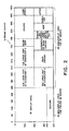
- pixels ranged between 0-399 in height and between 0-319 in width are assigned to a display area 41 depicted in Fig. 2 and the other pixels in the other range are assigned to a non-display area.
- the size of the display area 41 may vary for each game or scene of the game based on resolution of the game.
- the display area 41 includes a height of 400 pixels by a width of 320 pixels, but when images are required to display on the monitor 10 at higher resolution, larger size of the display area, such as an area of a height of 400 pixels by a width of 512 pixels, is required. Therefore, when different images are displayed to the same size on the monitor 10, one image having a height of 400 pixels by a width of 512 pixels is displayed at higher resolution than the resolution of the other image having a height of 400 pixels by a width of 320 pixels. This is because the former image has larger number of pixels in the same display area. Also, when the capacity of the display area 41 is increased, the capacity of the non-display area is reduced and the size or the number of patterns of images stored in the non-display area are limited, since the frame buffer 9 has the fixed capacity (herein, one megabytes).
- the non-display area of the frame buffer 9 includes a non-display area for pseudo 3D images 42 and a non-display area for 2D images 43.
- the non- non-display area for pseudo 3D images 42 resides in an area which is ranged between 0-319 in width and between 400-511 in height, is assigned to store data which are used to produce the pseudo 3D images, that is texture.
- the non-display area for 2D images 43 resides in an area other than the display area 41 and the non-display area for pseudo 3D images 42, and is assigned to store data which are used to produce the 2D images, that is animation images etc.
- the non-display area for 2D images 43 is divided into several sections based on categories of an object to be displayed to simplify management of the images.
- the size of the non-display area for pseudo 3D images 42, the size of the non-display area for 2D images 43, and the sections in the non-display area for 2D images 43 may vary for each game or scene of the game, as similar to the display area 41.
- the frame buffer 9 shown in Fig. 2 may be used, for example, in the following game.
- a user of the game selects two characters among three characters (character 1 to 3) and controls them to perform a various of operations, for example, to combat with enemy characters using the controller 20. Movements of the characters are displayed using pseudo 3D images. Under a certain condition, the upper part of two or three characters are displayed using 2D images and the user has a conversation with the characters in the game. In this point, the pseudo 3D images are displayed as background of the 2D images. In some case, the 2D images are displayed as background. The 3D images displayed as background may be continuously changed based on a predetermined routine simultaneously with change of the 2D animation images.
- Fig. 3 shows the actual data in the frame buffer 9 stored along with the layout of the frame buffer shown in Fig. 2. However, representation is omitted about the actual data in a right part of the frame buffer shown in Fig. 3.
- the free buffer 9 is divided sections each of which has the size of 64 pixels wide x 256 pixels height. However, these sections are defined in order to simplify management and ease understanding. Furthermore, an area which is ranged between 0-319 in width and between 0-399 in height is a display area 51 which corresponds to the display area 41 Shown in Fig. 2. In Fig. 3, no data are shown in the display area 51, but when the user play the game, images to be displayed on the monitor 10 are repeatedly produced in the display area 51 at high-speed, such as 10 frames per second to 60 frames per second.
- a color of each pixel may be represented by relating the pixel to a color identification number which is defined by the CLUT.
- each pixel itself has color information (for example, a set of values of RGB) and the pixel is colored by the color information. Therefore, an image defined as the display area 51 is directly displayed on the monitor 10 connected to the video game device.
- a texture 52 is stored in a location corresponding to the display area for pseudo 3D images 42 shown in Fig. 2.
- the texture 52 includes a dozens of expression patterns of enemy character's eye. In a game, one of the expression pattern is selected according to a status of an enemy character and the selected pattern is put on a polygon in a location corresponding to the enemy character's eye.
- Images required to represent a character 1 as 2D image are stored in a location corresponding to the area to be stored to represent the upper part of character 1 in the non-display area for 2D images shown in Fig. 2.
- the images in the area includes a plurality of stripped images and it is not clear what the images subsequently represent. However, when a part of images are selected and combined based on instructions from the CPU 1, groundwork for an image of the upper part of character 1 is produced in the display area 41.
- each of the stripped images may be stored in an orientation (for example, lengthwise or breadthwise) different from that of the image to be displayed.
- the image when a rectangular image (representing an eye and including a width of 20 pixels by height of 10 pixels) is put on a location in the display area 51, the image is generally stored in the non-display area for 2D images 43 in the same orientation as the image to be displayed in the area 51. However, there may be no space in the area 51 to store the rectangular image in the original orientation.
- the rectangular image when the area includes an empty space defined a width of 10 pixels by a height of 20 pixels, the rectangular image may be stored in the area 51 as an image having a width of 10 pixels by a height of 20 pixels by rotating the image clockwise (or counterclockwise) by an angle of 90 degrees. The image is rotated back counterclock-wise (or clockwise) by an angle of 90 degrees when the image is put on the display area 51.
- the area corresponding to the area of the upper part of character 1 shown in Fig. 2 further includes changed images which are used to display a part of the character 1 which changes.
- the changing parts of the character 1 in the display area 51 is replaced with the corresponding changed images and displayed on the monitor 10.
- another changed image is put on a part of the character 1 in the display area 51 and displayed on the monitor 10.
- the unit may be reduce to a pixel, then efficiency of usage of the frame buffer become the best in that unchanged data is not stored redundantly.
- the unit is small, the number of putting images on the display area 51 tends to be increased, as a result, load of the CPU 1 is increased.
- the size of the image to be prepared should be determined by comparing the merit that the frame buffer 9 is used effectively with the demerit described above. Also, the size of the image is not always fixed for all the images.
- the stripped image data is illustrated in connection with display of 2D image, however, the stripped image data may also be applied to the textures 52 which are used to display the pseudo 3D image.
- the capacity of image data which are used to display the pseudo 3D images is extremely saved in addition to the reduction of the required capacity of the frame buffer.
- the capacity of textures which are mapped to polygons becomes huge, however in the invention, the textures are mapped to only polygons in a part of a face (for example, a part of the face such as eye) of a main character and mapping to the other polygons is avoided.
- the frame buffer 9 shown in Fig. 3 is merely illustrated. Indeed, all the areas in the frame buffer 9 are filled with images except for the display area 51. Further, images shown in the frame buffer 9 are displayed with a vertical length which is longer than a vertical length actually displayed on the monitor 10, but this is not essential since difference of an aspect ratio for arrangement of pixels.
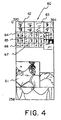
- Fig. 4 shows an enlarged area 60 corresponding to the area which is shown in Fig. 3 and ranged between 320-383 in width and between 0-255 in height.
- This area 60 stores images which may represent motion (change) of a character for a certain period in a game. Therefore, there are a plurality of images for the same part of the character.
- the area 60 stores images corresponding to a part of the character such as eyes (62-65) and months (66, 67) in the upper section.
- the area 60 further stores images corresponding to an outline of the character such as the whole upper part (61) and a body.
- images corresponding to eyes (62-65) the images which resides in the first and second rows including images 62 and 63 are used to represent a plurality patterns of left eyes of the character (right side of the character as you race him/her).
- the images which resides in the third and fourth rows including images 64 and 65 are used to represent a plurality patterns of right eyes of the character (left side of the character as you face him/her).
- Figs. 5A and 5B show images which are produced using the images in the area 60 shown in Fig. 4.
- Fig 5A shows image 71 displayed at a time point.
- Fig. 5B shows image 72 displayed at a frame next or after a several frames later from the image 71.
- the image 61 in the area 60 shown in Fig. 4 end an image represent the upper part of head (read from an are other than the area 60) are concatenated to produce an image of the upper part of the character, and the concatenated image is stored into the display area of the frame buffer 9.
- areas corresponding to eyes and mouth are empty.
- the image 62 in the area 60 is put on an area corresponding to a left eye of the character and the image 64 in the area 60 is put on an area corresponding to a right eye.
- image 66 in the area 60 is put on the area corresponding to the mouth.
- the image 71 is produced to represent a usual expression.
- the image 72 shown in Fig. 5B is produced by overlapping the changed images on the image 71.
- the image 63 in the area 60 shown in Fig. 4 is overlapped on the area corresponding to the left eye and the image 65 is overlapped on the area corresponding to the right eye.
- the image 67 in the area 60 is overlapped on the area corresponding to the mouth to produce the image 72 which represents the expression of the character who closes eyes and start talking.
- the desirable size of the area depends on characteristic of game images which transit for a period of time. Therefore, the size of the area is manually determined after trial and error. However, if a series of game images may be all read as data, using a computer, the following process may be performed. The process causes a load of developer of a game to reduce remarkably.
- the process executes the steps of focusing a series of movement of a character, selecting a plurality of images representing the movement of the character, accumulating parts which occur at least one change among the selected images, defining a plurality of rectangular areas so that the parts may be all covered.
- the rectangular area is divided into a plurality of smaller size of rectangular areas.
- the process further executes steps of accumulating parts which occur at least one change in the divided rectangular area, and defining the smallest rectangular area so that the parts may be all covered.
- the accumulating step and the defining step are repeated until size of the each defined area are reduced to be desirable.
- images representing the changing part are prepared in a unit of the defined desirable size of rectangular area.
- images representing eye or mouth are defined in a unit of the size covering the eye or the mouth. The images then transferred to the frame buffer 9.
- the desirable size depends on the power of expression of the game, or a period which a game should continue displaying images without replacing the frame buffer.
- Fig. 6 shows a flowchart of the steps.
- the process is started when the storage medium 17 is set to the video game device which has been powered on, or when the video game device is powered on with the storage medium 17 in the video game device.
- the storage medium drive 16 reads out images, voice, and program data from the storage medium 17 in step S10.
- the decoder 14 performs ECC operation on the read data and stores the data into the main memory 5. But, the voice data may be directly transferred to the sound processor 11 as required and then the voice data are stored into the sound buffer 12 in step S11.
- step S12 the program data stored in the main memory 5 are started as game program.
- the expansion circuit 7 performs expansion operation on the image data stored in the main memory 5 based on its compressed format, and stores back the data into the main memory 5 in step S13.
- step S14 image data which are used to produce 2D images and pseudo 3D images required for a predetermined period time (i : a period in the game) are transferred from the storage medium 17 or the main memory 5 to the non-display area in the frame buffer 9. At this point, a plurality of image data are stored in predetermined locations in the free buffer 9 as shown in Fig. 3.
- the predetermined period time i is not the fixed period, for example five or twenty minutes, but a predetermined game period which the game may continue displaying images on the monitor 10 using only once stored image in the frame buffer 9. Therefore, when a various of scenes and a plurality of colorful images are frequently used, the predetermined period time becomes comparatively short since the number of patterns of image to be used becomes large.
- the predetermined period time becomes comparatively long since only using images in the non-display area, display of the image on the monitor 10 continues for a long time.
- the predetermined period time is extended in the two cases since each changing part of the image is stored as a small area of image data into the frame buffer 9.
- step S15 it is determined whether or not images to be displayed next frame belongs to the current predetermined period time based on the scenario of the game or user's instructions. If the images belongs(step S15(Y)), process proceeds to step S16.
- step S16 required calculations about the pseudo 3D image are performed by the CPU 1.
- the CPU 1 determines coordinates (polygon vertex coordinates) of each vertex of each polygon in the 3D space to be displayed, and address data (in the non-display area in the frame buffer 9) of textures put on each polygon.
- the CPU 1 determines address data in the non-display area of the frame buffer 9 in which image data corresponds to the changed part are stored to replace only the changed part.
- step S17 each of the polygon vertex coordinates in the 3D space determined in step S16 is supplied to the graphics processor 3, and then the polygon vertex address data and brightness of the corresponding texture etc. are determined so that that the polygon vertex coordinates in the 3D space may be represented to the monitor in 2D space.
- a required calculation for displaying the 2D image is performed by the CPU 1.
- the CPU 1 determines the first address data in the display area of the frame buffer 9 and second address data in the non-display area of the frame buffer 9.
- the first and the second address data are of animation images prepared to display image.
- address data of the corresponding new image in the non-display area are determined in order to replace the changed area with the corresponding new image.
- step S19 required data, which are obtained from steps S16 to S18, about the pseudo 3D images and the 2D images is supplied to the graphic processor 8. Then, the graphic processor 8 produces a game image to be displayed on the monitor 10 from the supplied data and stores into the display area of the frame buffer 9.
- the graphic processor 8 produces a game image to be displayed on the monitor 10 from the supplied data and stores into the display area of the frame buffer 9.
- each of the textures in the non-display area is put on the corresponding polygon to produce the pseudo 3D images, and then the animation images in the non-display area are overlapped on the pseudo 3D images.
- step S20 when producing of the game image in the display area is completed, the contents of the game image are transferred to the monitor 10 at high-speed.
- step S21 it is determined whether or not there is an instruction (for example, to display a menu or to move an object) from a user via the controller 20 and the interface circuit 18.
- step S21(N) When there is no instruction (step S21(N)), process goes back to step S15.
- step S21(Y) process proceeds step S22, analyzes the instruction, and goes back to step S15. The instruction is evaluated in step S15 and processing corresponding to the instruction is performed.
- Processing in the loops between steps S15 and S21, and steps S15 and S 22 is performed at high-speed in a game displaying moving images to the monitor 10.
- the processing is repeated 10-60 times per second (that is, 10-60 frames per second (fps)).
- step S15 when it is determined that the current scene does not belong to the period i no longer (step S15(N)), process goes to step S23 and determines whether the game ends or not. When it is determined that the game ends (step S23(Y)), the process terminates. The game is ended by a various of events such as user's instruction (for example, suspend instruction and terminate instruction).
- step S24 When it is determined that the game is still continued (step S23(N)), process goes to step S24. This is when a scene of the game is drastically or dramatically changed, as a result, replacing of contents in the non-display area of the frame buffer 9 occurs. Therefore, in step S24, the period is set to the period i + 1 which is next to the period i, image data required in the period i + 1 are read out from the storage medium 17 or from the main memory 5. Then, process return to step S13, wherein expansion process are performed on the image data from the storage medium 17. Then, in step S14, the image data are stored into the non-display are of the frame buffer 9.
- a video game device may use a plurality of frame buffers, but even in this case, according to the invention, the non-display area in the frame buffers may be used efficiently.
- Fig. 7 shows an image displayed on the monitor 10 at one time point.
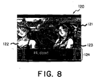
- Fig. 8 shows another image displayed on the monitor 10 at another time point.
- Fig. 9 shows still another image displayed on the monitor 10 as a frame next to the image shown in Fig. 8.
- the image 100 shown in Fig. 7 represents combat scene in a town 101, and wherein, two characters (102, 103) shoot at an enemy character 104 based on instructions of user via the controller 20.
- two characters drive the enemy character into the depth of the town based on the instructions of user
- a viewpoint of the game moves to the depth of the town according to the movement of the characters because the image 100 is represented using the pseudo 3D images.
- the image 120 shown in Fig. 8 represents two characters (122, 123) displayed using the 2D animation images with a background representing a town and displayed using the pseudo 3D images. Furthermore, in the lower part of the image 120, an area 124 is located and a talk of the characters (122, 123) is represented as letters in the area 124.
- the image 120 shows a scene when the two characters (102, 103) shown in Fig. 7 need to have a conversation in combating. To represent this situation, the upper part of the characters are shown on the image 100 shown in Fig. 7 in close-up style.
- the character 122 shown in Fig. 8 corresponds to the character 102 shown in Fig. 7.
- the character 123 shown in Fig. 8 corresponds to the character 103 shown in Fig. 7.
- the characters (102, 103) are shown in small size as fitted into the background in Fig. 7, but when a condition is satisfied, the characters are shown in more detail as 2D images of enlarged upper part of the characters.
- the image 140 shown in Fig. 9 shows two characters (142, 143) which are displayed using the 2D animation images and who are substantially the same as characters shown in Fig. 8 with background which is displayed using the pseudo 3D image and represents the town as similar to the town shown in Fig. 8. Further, the image 140 includes an area 144 as similar to the area 124 in the lower part, and a talk of the characters (142, 143) is displayed in the area 144.
- the character 142, 143 in Fig. 9 are different from the corresponding characters 122, 123 in Fig. 8 in that the size of the opening mouth and the opening eyes, and the form of hair are different from each other.
- the images shown in Fig. 8 and Fig. 9 represent only two scenes which are very close in time. However, when such a change between the images is supplied over a great number of frames, the characters etc. are added to expression of natural motion.
- expression of talking characters is realized by changing the size of opening month one after another.
- expression of flowing hair in the wind is realized by changing the form of hair in order.
- the transitional change is performed by replacing only the changed part of the image (for example, only mouth part or only front hair part) in the display area of the frame buffer 9 with the corresponding new area.
- the 2D images and the pseudo 3D images may be displayed simultaneously on the display device.
Abstract
Description
- The invention relates to a video game apparatus and method for displaying images of game, and storage medium storing programs for causing a computer to execute the method, in particular, to a method of displaying the images using a buffer effectively.
- In recent years, the video games have widely spread to families. Furthermore, the kinds of the games are put on a wide range of types including role playing game, simulation game, fighting game, puzzle game and so on.
- Also, there are a wide variety of types of video game apparatuses which are used to play the video games. The video game apparatus may be home-use video game apparatus including a television monitor, or a personal. computer/workstation including CRT display device, and the images of games are displayed in the television monitor or the CRT display device. Further, the video game apparatus may also be an arcade video game apparatus which is located at, for example, a game center and which has a body incorporated with a display device.
- In the previous video game apparatuses, same display a series of animated images by changing 2D images one after another, and others by using 3D images, which represent images of the video game in perspective and changes the images according to movement of a viewpoint of a player/an object character of the video game (namely, pseudo 3D images). Further, some of these video game apparatuses have the both displaying methods.
- The method of displaying the pseudo 3D images brings the video game dynamical effect and the feeling of being at a live performance by representing objects (characters/bodies) in three dimensional style.
- Indeed, the method displays the pseudo 3D images by displaying and combining a plurality of polygons models. The surface of each polygon is filled with a pattern and/or shade and then the feel of a material is represented. The pattern and shade may be painted on the polygon by putting a predetermined texture which is a 2D image on the surface of the polygon (namely, texture mapping) or by shading the surface of the polygon based on a pseudo light source which is located in a pseudo 3D space.
- Most of the video game apparatuses include a frame buffer which can achieve high speed transmitting of data between the video game apparatus and display device connected to the video game apparatus. Therefore, to display images of games on the display device, the video game apparatus firstly produces data of the image in an area in the frame buffer and secondly transfers the data of the image to the display device.
- A first problem is that there is no previous video game apparatus which can display both the 2D image and the pseudo 3D image on the display device. Using only the 2D image, it is not possible to achieve three dimensional effect such as depth (perspective) anti movement of a view point. On the other hand, using only pseudo 3D image, it is not possible to represent an expression of a people (an object character of a game) in detail. Therefore, to display both the 2D image and the pseudo 3D image is extremely advantageous in that the both of the images complement each other. The main reason why the representation is not achieved in detail in using the pseudo 3D image is that the previous video game apparatus does not have enough power to process polygon images of high-resolution in real-time.
- Herein, an image displayed by the 2D image and the pseudo 3D image is, for example, an image including a close-up image of the upper part of two people and a background image of perspectively represented street. The background image is changed according to a viewpoint of a player/an object character of a game.
- Also, in addition to the image data which are supplied to the display device in original aspect, a series of animation images (2D image) or textures (pseudo 3D image), which are used to produce images, may be stored in the frame buffer. In general, the animation images are a series of images which can represent a moving character, but herein, the animation images are also a series of images which can represent changes of display location of the character.
- The video game apparatus produces and stores into the frame buffer a plurality of images which are supplied according to transition of story of the video gems in order.
- In such a case, the storing of the images to the frame buffer is carried out because it is not possible to prepare whole the images before the images are required if data which are used to produce the images are read from a medium of low access speed, such as an external storage device. That is, it is not possible to produce the image at 10 to 60 frames per second, when the required data are read from the external storage device.
- When the images are displayed using the method which the images are previously stored in the frame buffer, to display both the 2D image and the pseudo 3D image simultaneously, it is required that both data including the animation images from which the 2D image is configured and data including the textures from which the pseudo 3D image is configured are stored in the frame buffer. This leads to an increase of amount of data which are required at a period of time in a game, and consequently, causes a game device to hesitate more frequently due to rewriting of data in the frame buffer.
- In the method which the images are previously stored in the frame buffer, when scene of the game is dramatically changed, for example characters in the game and the background become quite another, as a result, data which are required to produce the new changed image are absent in the frame buffer, it is required that contents in the frame buffer are rewritten to the required data. This rewriting process is to transfer the data from the storage medium or the main memory to the frame buffer. In particular, when the data are transfer from the storage medium to the frame buffer, it takes several seconds to transfer the data. In some case, it takes long time enough to suspend the game.
- Especially, in the game having thrilling story or dynamic continuous movement, the suspension of the game dampen the interest of the user and may become a fatal defect. Therefore, the suspension of the game must be avoided at any cost.
- However, capacity of the frame buffer is generally about one megabytes to four megabytes and is restricted based on hardware configuration. Therefore, it is not easy to increase the capacity of the frame buffer. Because of this, in general games, the suspensions happen several times or dozens of times from the start of the game to the end of the game due to the rewriting.
- The simplest way to avoid the suspensions due to rewriting is to rewrite at the scene which is insensitive to the suspension. Generally, in a game, there are some scenes where the user vacillates this way and that without operations or no updating of the image is required. If the rewriting of the image is executed in such scenes, user seems that the story of the game proceeds without hesitation. However, the technique often depends of nature, contents, story of the game. Therefore, the technique has restriction in that the time points when the rewriting of the image should be executed are limited to some timings.
- Another technique to avoid the hesitation is to analyze the story of the game, strictly select the required data in the frame buffer, and partially store the required data (a small amount of data at a time) in an area where the unused data are stored. Thereby, rewrite processes are distributed and it is possible to reduce the probability that user seems that the game suspends. However, in this technique, it should be determined which data in the frame buffer are required for each scene of the game. The determination depends on the pattern of transition of the story of the game, as a result, extremely increases the complexity of the design of the game and the load of the CPU of the game device.
- Still another method to avoid the hesitation is to reduce the amount of data in the frame buffer. As a result, the number of rewritings of the frame buffer is reduced or become zero. However, this leads to reduce the number of colors or image pattern. A game using a small number of colors may not have great power of expression, and a game which repeat displaying of the same scenes or the same characters may not supply strong impression to the users. Therefore, these game may not compete on the market in view of development of many types of games.
- Thus, aforementioned techniques include fatal defects and the suspension problem due to rewriting of the frame buffer is not resolved essentially.
- Therefore, it is an object of the invention to provide a video game device, image display method, and storage medium for simultaneously displaying a 2D image and a pseudo 3D image on a display device.
- It is another object of the invention to provide a video game device, image display method, and storage medium which may not require to rewrite data in a frame buffer for a long time without dependency on contents, nature, and story of the game, without increasing complexity of game program and load of CPU, and without reducing power of expression and impression of the game.
- According to a first aspect of the invention, there is provided a video game device having a frame buffer which includes a first area storing a first image used in a game, and a game image displaying device which displays the first image to a display device. The video game comprises a game image producing device which produces the first image on the basis of proceedings of the game by combining a 2D image and pseudo 3D image and a game image storing device which stores the first image into the first area. Further, the game image displaying device displays the first image which is produced by the game image producing device and is stored by the game image storing device into the first area, to the display device.
- According to the video game device of the invention, it is possible to display the 2D image which may represent a detail expression of a character and the pseudo 3D image which may represent a 3D space in which images are changed according to a viewpoint of the character, to the display device simultaneously.
- According to a second aspect of the invention, there is provided another video game device having a frame buffer which includes a first area storing a first image used in a game, and a game image displaying device which displays the first image stored in the first area to a display device. The video game device comprises a second area which is included in the frame buffer and stores second images used to produce the first image, a game image producing device which when the first image includes change parts which change according to passage of time, reproduces the first image by using the second images which correspond to the change parts of the first image, and a game image storing device which stores the reproduced first image into the first area. Furthermore, the game image displaying device displays the reproduced first image to the display device, each of the second images is partial image subdivided in a predetermined size, each of the second images is stored in the second area in consideration of a relationship of an orientation between an image to be stored in the second area and the image to be displayed, and the size, the location, and the orientation of each of the second images to be stored into the second area is optimized so that the interval of accessing to a storage medium other than the frame buffer for producing the first game image is extended.
- According to the video game device, it may not require to rewrite data in a frame buffer for a long time without dependency on contents, nature, and story of the game, without increasing complexity of game program and load of CPU, and without reducing power of expression and impression of the game.
- Fig. 1 shows a block diagram of a video game device according to an embodiment of the invention;
- Fig. 2 shows an example of an layout of a frame buffer of the video game device according to an embodiment of the invention;
- Fig. 3 shows contents of the frame buffer shown in Fig. 2;
- Fig. 4 shows an enlarged view of a part of the contents of the frame buffer shown in Fig. 3;
- Fig. 5A and 5B show image examples which are produced using the contents of the frame buffer shown in Fig. 3:
- Fig. 6 shows a flow chart representing rendering and displaying process at a video game device according to an embodiment of the invention;
- Fig. 7 shows an example of image displayed on a monitor at a time point according to an embodiment of the invention;
- Fig. 8 shows an example of image displayed on a monitor at another time point according to an embodiment of the invention; and
- Fig. 9 shows an example of image to be displayed as a frame next to the image shown in Fig. 8.
-
- Fig. 1 shows a block diagram of a video game device which may achieve the invention. The video game device is the same as a device disclosed in JP-A- 08-235366
- As shown Fig. 1, the video game device implementing the invention includes a body and elements which are connected to the body. The elements include a
television monitor 10,speaker 13,memory card 19, acontroller 20. The configuration of the video game device is an example for a game device for family use. - The body further includes a
CPU 1, abus 2 which is connected to theCPU 1, and constituents which are connected to thebus 2. - The
bus 2 is configured of an address bus, a data bus, and a control bus. And a graphicsdata generating processor 3, aperipheral device controller 4, amain memory 5, aROM 6, anexpansion circuit 7, agraphic processor 8, aframe buffer 9, asound processor 11, asound buffer 12, adecoder 14, abuffer 15, astorage medium drive 16, and aninterface circuit 18 are connected to thebus 2. - Also, the television monitor 10 (hereinafter, is simply referred to as "monitor") is connected to the
graphic processor 8, thespeaker 13 is connected to thesound processor 11, and thememory card 19 and thecontroller 20 are connected to theinterface circuit 18. - The
storage medium 17 stores a program and data which are required to execute a game. The contents of the program and the data are supplied via thestorage medium drive 16 to the game device. The storage medium includes, for example, a portable storage medium, such as a cd-rom and an optical disk. - As described above, this configuration is adapted to a game device for family use. In this case, for example, the
monitor 10 may be a monitor of a domestic television, and thespeaker 13 may be a speaker of the domestic television. - In the case where an arcade game device implements the method of the invention, the elements shown in Fig. 1 may be incorporated to one package.
- Alternatively, when a personal computer or a workstation computer implements the method of the invention, the
monitor 10 may be a CRT display connected to the computer, and thecontroller 20 may be an input device, such as a keyboard or mouse of the computer. - Next, more detailed description is made about the constituents shown in Fig. 1. The
CPU 1 depicted is, for example, a 32-bit RISC (reduced instruction set computer) CPU, which controls the whole device by executing the operating system stored in theROM 6. - The graphics
data generating processor 3 serves as a co-processor of theCPU 1. That is, the graphicsdata generating processor 3 performs co-ordinates conversion and light source calculating (for example, calculation of matrix including fixed point elements and vector operation) in parallel in order to display a pseudo 3D image. - The peripheral,
device controller 4 performs interrupt control, time control, memory control, and control for direct access memory (DMA) transfer. - The
Rom 6 stores the operating system which controls operation on each element. - The
expansion circuit 7 decodes still or animated image data read out from thestorage medium 17 and stored in themain memory 5, under the control of theaforementioned CPU 1, and stores the decoded image data back in themain memory 5. Specifically, theexpansion circuit 7 is capable of high-speed execution of inverse discrete cosine transform (inverse DCT) operations, and it is also capable of expending compressed data read out from thestorage medium 17 in accordance with still color image compression standards (known as JPEG) or cumulative media moving image encoding standards (known as MPEG). - The
graphic processor 8 renders polygon images and stores them into theframe buffer 9 in response to instructions from theCPU 1. - The
frame buffer 9 includes display area and non-display area. The display area is an area in which images corresponding to a display area on themonitor 10 are stored. The non-display area is an area in which animation images used to produce 2D images in the display area and textures used to produce pseudo 3D images are stored. - In some case, the
frame buffer 9 includes a color lookup table (CLUT) which corresponds a color of pixel to a number. Also, data in the display area in theframe buffer 9 are transferred to themonitor 10 at high-speed. Theframe buffer 9 consists of a so-called dual-port RAM, and it is capable of simultaneously receiving images from the graphics data generating processor 3 (CPU 1) or transferring data from themain memory 5, and reading out data in order that the data can be displayed to themonitor 10. - The
sound processor 11 outputs music or an effective sound viaspeaker 13 by regenerating ADPCM data in thestorage medium 17 or voice data stored in thesound buffer 12, or by modulating and regenerating the voice data. - The
decoder 14 decodes a program or data which are stored in thestorage medium 17 and are appended an error checking and correction (ECC) code, and provides the program or the data to themain memory 5 or thesound processor 11. - The
buffer 15 temporarily stores the program and/or data regenerated from thestorage medium 17. Thebuffer 15 is, for example, 32 kilobytes of buffer. - The
storage medium drive 16 may be cd-rom drive, optical disk drive and the like. Thestorage medium drive 16 reads out a program and another data from thestorage medium 17, and provides them to thedecoder 14. - The
interface circuit 20 sends an operation signal received from thecontroller 20 to theCPU 1. Also, theinterface circuit 20 reads out the contents of thememory card 19 to supply the contents to themain memory 5, simultaneously that, stores data into thememory card 19 in response to an instruction of theCPU 1. - The
memory card 19 stores values of a various of parameters in order to, for example, maintain the status at the time point when a game terminates last time. Herein, a card type memory is used as thememory card 13, but many types of memories may be used. - The
controller 20 is used to play a game by a user. Thecontroller 20 includes direction buttons for moving a character on the monitor upwards, downwards, leftwards and rightwards, and a plurality of function buttons for instructing one of specific functions, for example, starting the game or selecting items. - Next, the contents of the
frame buffer 9 in a video game device according to the invention are described in more detail with reference to Fig. 2. Theframe buffer 9 includes a capacity of a height of 512 pixels by a width of 1024 pixels and there is two bytes (sixteen bits) of information for each pixel. Therefore, whole capacity of theframe buffer 9 is 1,048,576 bytes (512 x 1024 x 2 bytes), that is one megabytes. - In this event, the pixels along the width may be called zero-th through 1023-th pixels (0 to 1023) while the pixels along the height may be called zero-th through 511-th pixels (0 to 511).
- In the
frame buffer 9, pixels ranged between 0-399 in height and between 0-319 in width are assigned to adisplay area 41 depicted in Fig. 2 and the other pixels in the other range are assigned to a non-display area. - The size of the
display area 41 may vary for each game or scene of the game based on resolution of the game. In this case, thedisplay area 41 includes a height of 400 pixels by a width of 320 pixels, but when images are required to display on themonitor 10 at higher resolution, larger size of the display area, such as an area of a height of 400 pixels by a width of 512 pixels, is required. Therefore, when different images are displayed to the same size on themonitor 10, one image having a height of 400 pixels by a width of 512 pixels is displayed at higher resolution than the resolution of the other image having a height of 400 pixels by a width of 320 pixels. This is because the former image has larger number of pixels in the same display area. Also, when the capacity of thedisplay area 41 is increased, the capacity of the non-display area is reduced and the size or the number of patterns of images stored in the non-display area are limited, since theframe buffer 9 has the fixed capacity (herein, one megabytes). - The non-display area of the
frame buffer 9 includes a non-display area forpseudo 3D images 42 and a non-display area for2D images 43. The non- non-display area forpseudo 3D images 42 resides in an area which is ranged between 0-319 in width and between 400-511 in height, is assigned to store data which are used to produce the pseudo 3D images, that is texture. The non-display area for2D images 43 resides in an area other than thedisplay area 41 and the non-display area forpseudo 3D images 42, and is assigned to store data which are used to produce the 2D images, that is animation images etc. - The non-display area for
2D images 43 is divided into several sections based on categories of an object to be displayed to simplify management of the images. The size of the non-display area forpseudo 3D images 42, the size of the non-display area for2D images 43, and the sections in the non-display area for2D images 43 may vary for each game or scene of the game, as similar to thedisplay area 41. - The
frame buffer 9 shown in Fig. 2 may be used, for example, in the following game. In the game, a user of the game selects two characters among three characters (character 1 to 3) and controls them to perform a various of operations, for example, to combat with enemy characters using thecontroller 20. Movements of the characters are displayed using pseudo 3D images. Under a certain condition, the upper part of two or three characters are displayed using 2D images and the user has a conversation with the characters in the game. In this point, the pseudo 3D images are displayed as background of the 2D images. In some case, the 2D images are displayed as background. The 3D images displayed as background may be continuously changed based on a predetermined routine simultaneously with change of the 2D animation images. - Using the 2D animation images, the character who has a conversation is displayed naturally on the
monitor 10 since a mouth, hair, and an expression of the character change delicately. - Then, description is made about an actual data in the
frame buffer 9 with reference to Fig. 3. Fig. 3 shows the actual data in theframe buffer 9 stored along with the layout of the frame buffer shown in Fig. 2. However, representation is omitted about the actual data in a right part of the frame buffer shown in Fig. 3. - In Fig. 3, the
free buffer 9 is divided sections each of which has the size of 64 pixels wide x 256 pixels height. However, these sections are defined in order to simplify management and ease understanding. Furthermore, an area which is ranged between 0-319 in width and between 0-399 in height is adisplay area 51 which corresponds to thedisplay area 41 Shown in Fig. 2. In Fig. 3, no data are shown in thedisplay area 51, but when the user play the game, images to be displayed on themonitor 10 are repeatedly produced in thedisplay area 51 at high-speed, such as 10 frames per second to 60 frames per second. - As described above, a color of each pixel may be represented by relating the pixel to a color identification number which is defined by the CLUT. However, herein, each pixel itself has color information (for example, a set of values of RGB) and the pixel is colored by the color information. Therefore, an image defined as the
display area 51 is directly displayed on themonitor 10 connected to the video game device. - A
texture 52 is stored in a location corresponding to the display area forpseudo 3D images 42 shown in Fig. 2. Thetexture 52 includes a dozens of expression patterns of enemy character's eye. In a game, one of the expression pattern is selected according to a status of an enemy character and the selected pattern is put on a polygon in a location corresponding to the enemy character's eye. - Images required to represent a
character 1 as 2D image are stored in a location corresponding to the area to be stored to represent the upper part ofcharacter 1 in the non-display area for 2D images shown in Fig. 2. The images in the area includes a plurality of stripped images and it is not clear what the images subsequently represent. However, when a part of images are selected and combined based on instructions from theCPU 1, groundwork for an image of the upper part ofcharacter 1 is produced in thedisplay area 41. - In this example, the stripped images are stored in the same orientation as the orientations of images to be displayed in the
display area 51. However, in order to use theframe buffer 9 effectively, each of the stripped images may be stored in an orientation (for example, lengthwise or breadthwise) different from that of the image to be displayed. - Specifically, when a rectangular image (representing an eye and including a width of 20 pixels by height of 10 pixels) is put on a location in the
display area 51, the image is generally stored in the non-display area for2D images 43 in the same orientation as the image to be displayed in thearea 51. However, there may be no space in thearea 51 to store the rectangular image in the original orientation. In this case, when the area includes an empty space defined a width of 10 pixels by a height of 20 pixels, the rectangular image may be stored in thearea 51 as an image having a width of 10 pixels by a height of 20 pixels by rotating the image clockwise (or counterclockwise) by an angle of 90 degrees. The image is rotated back counterclock-wise (or clockwise) by an angle of 90 degrees when the image is put on thedisplay area 51. - The area corresponding to the area of the upper part of
character 1 shown in Fig. 2 further includes changed images which are used to display a part of thecharacter 1 which changes. When the upper part of thecharacter 1 displayed in thedisplay area 51 changes a little according to the condition of a game or user's instruction (for example, when the character closes eye, or moves mouth to talk to, or hair flows in the wind), the changing parts of thecharacter 1 in thedisplay area 51 is replaced with the corresponding changed images and displayed on themonitor 10. In the next frame, another changed image is put on a part of thecharacter 1 in thedisplay area 51 and displayed on themonitor 10. By repeating such a process, for example, expression of hair ofcharacter 1 swaying in the wind any number of times is achieved. - Generally, delicate changes of an expression of the character is represented in a little part of an image of the character. Therefore, in this case, the part which is of the image of the
character 1 and substantially changes is very small. However, such an image data previously used are, for example, managed in a unit of face. Thus, when there are five image patterns that the character open/close his/her month to talk to, five images are required each of which corresponds to one of the pattern and includes whole face image. - According to the invention, in such a case, required capacity of image data is remarkably reduced because the image pattern is managed in a unit of a part of face, for example, a mouth.
- Proceeding this idea, the unit may be reduce to a pixel, then efficiency of usage of the frame buffer become the best in that unchanged data is not stored redundantly. However, if the unit is small, the number of putting images on the
display area 51 tends to be increased, as a result, load of theCPU 1 is increased. - Further, it is hard to collect a number of the tiny images. Therefore, the size of the image to be prepared should be determined by comparing the merit that the
frame buffer 9 is used effectively with the demerit described above. Also, the size of the image is not always fixed for all the images. - As similar to the
character 1, in areas corresponding to thecharacter 2 and thecharacter 3, images which corresponds to the changing part of the characters are prepared. Further, the stripped image data is illustrated in connection with display of 2D image, however, the stripped image data may also be applied to thetextures 52 which are used to display the pseudo 3D image. - In the above embodiment of the invention, using the stripped image data, the capacity of image data which are used to display the pseudo 3D images is extremely saved in addition to the reduction of the required capacity of the frame buffer. In general, the capacity of textures which are mapped to polygons becomes huge, however in the invention, the textures are mapped to only polygons in a part of a face (for example, a part of the face such as eye) of a main character and mapping to the other polygons is avoided.
- Further, there is no need to prepare textures of objects configuring a background in the
frame buffer 9, because the background and objects in the background which are generally represented using the pseudo 3D images including polygons are each represented by a image (the image is stored in the areas of background and elements of background in the non-display area for 2D images shown in Fig. 2). In the method, it is possible to further reduce the capacity required in theframe buffer 9 while maintaining power of expression in the pseudo 3D images to some extent. - The
frame buffer 9 shown in Fig. 3 is merely illustrated. Indeed, all the areas in theframe buffer 9 are filled with images except for thedisplay area 51. Further, images shown in theframe buffer 9 are displayed with a vertical length which is longer than a vertical length actually displayed on themonitor 10, but this is not essential since difference of an aspect ratio for arrangement of pixels. - Next, description is made about a process of replacing the changed part of an image with reference to Figs. 4 and 5.
- Fig. 4 shows an enlarged area 60 corresponding to the area which is shown in Fig. 3 and ranged between 320-383 in width and between 0-255 in height. This area 60 stores images which may represent motion (change) of a character for a certain period in a game. Therefore, there are a plurality of images for the same part of the character.
- The area 60 stores images corresponding to a part of the character such as eyes (62-65) and months (66, 67) in the upper section. The area 60 further stores images corresponding to an outline of the character such as the whole upper part (61) and a body. Herein, in the images corresponding to eyes (62-65), the images which resides in the first and second
rows including images rows including images - It is possible to produce a various expressions of character such as when the character cries or laughs by only replacing with the image representing eye of the character. The image representing eye is stored in a unit of eye (and eyebrow). Therefore, the capacity of the image is less than the capacity when the image is stored in a unit of face. In other word, a larger number of expressions may be represented using the same capacity.
- Figs. 5A and 5B show images which are produced using the images in the area 60 shown in Fig. 4. Fig 5A shows
image 71 displayed at a time point. And Fig. 5B showsimage 72 displayed at a frame next or after a several frames later from theimage 71. When images are displayed in the order Fig. 5A to Fig. 5B, it is seems that the character closes eye and is going to start talking. - Herein, method of producing each image is described. To produce the
image 71 shown in Fig. 5A, at first, theimage 61 in the area 60 shown in Fig. 4 end an image represent the upper part of head (read from an are other than the area 60) are concatenated to produce an image of the upper part of the character, and the concatenated image is stored into the display area of theframe buffer 9. At this point, areas corresponding to eyes and mouth are empty. Then, theimage 62 in the area 60 is put on an area corresponding to a left eye of the character and theimage 64 in the area 60 is put on an area corresponding to a right eye. Furthermore, image 66 in the area 60 is put on the area corresponding to the mouth. As a result, theimage 71 is produced to represent a usual expression. - The
image 72 shown in Fig. 5B is produced by overlapping the changed images on theimage 71. At first, theimage 63 in the area 60 shown in Fig. 4 is overlapped on the area corresponding to the left eye and theimage 65 is overlapped on the area corresponding to the right eye. Then, theimage 67 in the area 60 is overlapped on the area corresponding to the mouth to produce theimage 72 which represents the expression of the character who closes eyes and start talking. - It is possible to display images as the character moves continuously by producing the images as described above and displaying the images one after another. Herein, the changing part of the character is stored in a unit of small size area such as eye and mouth. Therefore, using even if a small capacity of the frame buffer, it is possible to obtain abundant power of expression.
- The desirable size of the area depends on characteristic of game images which transit for a period of time. Therefore, the size of the area is manually determined after trial and error. However, if a series of game images may be all read as data, using a computer, the following process may be performed. The process causes a load of developer of a game to reduce remarkably.
- At first, the process executes the steps of focusing a series of movement of a character, selecting a plurality of images representing the movement of the character, accumulating parts which occur at least one change among the selected images, defining a plurality of rectangular areas so that the parts may be all covered. Next, if the size of the rectangular area is not desirable, the rectangular area is divided into a plurality of smaller size of rectangular areas.
- Then, the process further executes steps of accumulating parts which occur at least one change in the divided rectangular area, and defining the smallest rectangular area so that the parts may be all covered. The accumulating step and the defining step are repeated until size of the each defined area are reduced to be desirable.
- As a result, images representing the changing part are prepared in a unit of the defined desirable size of rectangular area. For example, images representing eye or mouth are defined in a unit of the size covering the eye or the mouth. The images then transferred to the
frame buffer 9. - The desirable size depends on the power of expression of the game, or a period which a game should continue displaying images without replacing the frame buffer.
- Next, steps of rendering and displaying 3D images and pseudo 3D images according to an embodiment of the invention are described with reference to Fig. 6. Fig. 6 shows a flowchart of the steps.
- The process is started when the
storage medium 17 is set to the video game device which has been powered on, or when the video game device is powered on with thestorage medium 17 in the video game device. - At first, the
storage medium drive 16 reads out images, voice, and program data from thestorage medium 17 in step S10. - Then, the
decoder 14 performs ECC operation on the read data and stores the data into themain memory 5. But, the voice data may be directly transferred to thesound processor 11 as required and then the voice data are stored into thesound buffer 12 in step S11. - In step S12, the program data stored in the
main memory 5 are started as game program. - Next, the
expansion circuit 7 performs expansion operation on the image data stored in themain memory 5 based on its compressed format, and stores back the data into themain memory 5 in step S13. - In step S14, image data which are used to produce 2D images and pseudo 3D images required for a predetermined period time (i : a period in the game) are transferred from the
storage medium 17 or themain memory 5 to the non-display area in theframe buffer 9. At this point, a plurality of image data are stored in predetermined locations in thefree buffer 9 as shown in Fig. 3. - The predetermined period time i is not the fixed period, for example five or twenty minutes, but a predetermined game period which the game may continue displaying images on the
monitor 10 using only once stored image in theframe buffer 9. Therefore, when a various of scenes and a plurality of colorful images are frequently used, the predetermined period time becomes comparatively short since the number of patterns of image to be used becomes large. - On the other hand, when a monotonous scenes are simply displayed, the predetermined period time becomes comparatively long since only using images in the non-display area, display of the image on the
monitor 10 continues for a long time. - However, according to the invention, the predetermined period time is extended in the two cases since each changing part of the image is stored as a small area of image data into the
frame buffer 9. - In step S15, it is determined whether or not images to be displayed next frame belongs to the current predetermined period time based on the scenario of the game or user's instructions. If the images belongs(step S15(Y)), process proceeds to step S16.
- In step S16, required calculations about the pseudo 3D image are performed by the
CPU 1. TheCPU 1 determines coordinates (polygon vertex coordinates) of each vertex of each polygon in the 3D space to be displayed, and address data (in the non-display area in the frame buffer 9) of textures put on each polygon. When a part of the texture is changed, theCPU 1 determines address data in the non-display area of theframe buffer 9 in which image data corresponds to the changed part are stored to replace only the changed part. - Next, in step S17, each of the polygon vertex coordinates in the 3D space determined in step S16 is supplied to the
graphics processor 3, and then the polygon vertex address data and brightness of the corresponding texture etc. are determined so that that the polygon vertex coordinates in the 3D space may be represented to the monitor in 2D space. - Then, in stop S18, a required calculation for displaying the 2D image is performed by the
CPU 1. TheCPU 1 determines the first address data in the display area of theframe buffer 9 and second address data in the non-display area of theframe buffer 9. The first and the second address data are of animation images prepared to display image. Herein, when a part of the animation image is changed, address data of the corresponding new image in the non-display area are determined in order to replace the changed area with the corresponding new image. - Next, in step S19, required data, which are obtained from steps S16 to S18, about the pseudo 3D images and the 2D images is supplied to the
graphic processor 8. Then, thegraphic processor 8 produces a game image to be displayed on themonitor 10 from the supplied data and stores into the display area of theframe buffer 9. In the embodiment of the invention, firstly, each of the textures in the non-display area is put on the corresponding polygon to produce the pseudo 3D images, and then the animation images in the non-display area are overlapped on the pseudo 3D images. As described above, when a part of the images is changed, for example, a character displayed in an animation image closes his/her ayes, only an image which represents the eyes closed is read from the non-display area and the image is put on the display area in the corresponding location. - In step S20, when producing of the game image in the display area is completed, the contents of the game image are transferred to the
monitor 10 at high-speed. - In step S21, it is determined whether or not there is an instruction (for example, to display a menu or to move an object) from a user via the
controller 20 and theinterface circuit 18. When there is no instruction (step S21(N)), process goes back to step S15. When there is an instruction (step S21(Y)), process proceeds step S22, analyzes the instruction, and goes back to step S15. The instruction is evaluated in step S15 and processing corresponding to the instruction is performed. - Processing in the loops between steps S15 and S21, and steps S15 and
S 22 is performed at high-speed in a game displaying moving images to themonitor 10. In general, the processing is repeated 10-60 times per second (that is, 10-60 frames per second (fps)). - In step S15, when it is determined that the current scene does not belong to the period i no longer (step S15(N)), process goes to step S23 and determines whether the game ends or not. When it is determined that the game ends (step S23(Y)), the process terminates. The game is ended by a various of events such as user's instruction (for example, suspend instruction and terminate instruction).
- When it is determined that the game is still continued (step S23(N)), process goes to step S24. This is when a scene of the game is drastically or dramatically changed, as a result, replacing of contents in the non-display area of the
frame buffer 9 occurs. Therefore, in step S24, the period is set to the period i + 1 which is next to the period i, image data required in the period i + 1 are read out from thestorage medium 17 or from themain memory 5. Then, process return to step S13, wherein expansion process are performed on the image data from thestorage medium 17. Then, in step S14, the image data are stored into the non-display are of theframe buffer 9. - The order of the processing as described above, in particular the rendering process and the determination of user's instruction may vary. Therefore, the method of the invention should not be limited to the order. For example, processes in steps S16 - S17 and process in step S18 may be switched or performed simultaneously.
- Further, the method of the invention may apply to a video game device different from the embodiment of the invention. For example, a video game device may use a plurality of frame buffers, but even in this case, according to the invention, the non-display area in the frame buffers may be used efficiently.
- Next, description is made about an example of image displayed on the
monitor 10 according to an embodiment of the invention. - Fig. 7 shows an image displayed on the
monitor 10 at one time point. Fig. 8 shows another image displayed on themonitor 10 at another time point. Fig. 9 shows still another image displayed on themonitor 10 as a frame next to the image shown in Fig. 8. - The
image 100 shown in Fig. 7 represents combat scene in atown 101, and wherein, two characters (102, 103) shoot at anenemy character 104 based on instructions of user via thecontroller 20. When the two characters drive the enemy character into the depth of the town based on the instructions of user, a viewpoint of the game moves to the depth of the town according to the movement of the characters because theimage 100 is represented using the pseudo 3D images. - The
image 120 shown in Fig. 8 represents two characters (122, 123) displayed using the 2D animation images with a background representing a town and displayed using the pseudo 3D images. Furthermore, in the lower part of theimage 120, anarea 124 is located and a talk of the characters (122, 123) is represented as letters in thearea 124. - The
image 120 shows a scene when the two characters (102, 103) shown in Fig. 7 need to have a conversation in combating. To represent this situation, the upper part of the characters are shown on theimage 100 shown in Fig. 7 in close-up style. Thecharacter 122 shown in Fig. 8 corresponds to thecharacter 102 shown in Fig. 7. Thecharacter 123 shown in Fig. 8 corresponds to thecharacter 103 shown in Fig. 7. Thus, the characters (102, 103) are shown in small size as fitted into the background in Fig. 7, but when a condition is satisfied, the characters are shown in more detail as 2D images of enlarged upper part of the characters. - The
image 140 shown in Fig. 9 shows two characters (142, 143) which are displayed using the 2D animation images and who are substantially the same as characters shown in Fig. 8 with background which is displayed using the pseudo 3D image and represents the town as similar to the town shown in Fig. 8. Further, theimage 140 includes anarea 144 as similar to thearea 124 in the lower part, and a talk of the characters (142, 143) is displayed in thearea 144. - There is no difference between the contents of the backgrounds shown in Fig. 8 and Fig. 9. Further, in Figs. 8 and 9, the substantially same two characters are displayed in the same locations.
- However, comparing the characters shown in Fig. 8 with characters shown in Fig. 9, the
character characters - The images shown in Fig. 8 and Fig. 9 represent only two scenes which are very close in time. However, when such a change between the images is supplied over a great number of frames, the characters etc. are added to expression of natural motion. In this example, expression of talking characters is realized by changing the size of opening month one after another. Further, expression of flowing hair in the wind is realized by changing the form of hair in order.
- As described above, the transitional change is performed by replacing only the changed part of the image (for example, only mouth part or only front hair part) in the display area of the
frame buffer 9 with the corresponding new area. - According to the invention, the 2D images and the pseudo 3D images may be displayed simultaneously on the display device.
- Further, according to the invention, it in no need to rewrite data in the frame buffer for a long time in a game, without regard to the contents, the characteristics, and the story of the game, and without causing the power of expression and impression to degrade.
Claims (13)
- A video game device having a frame buffer (9) which includes a first area (41) storing a first image used in a game, and a game image displaying device which displays the first image to a display device (10), comprising:a game image producing device which produces the first image on the basis of proceedings of the game by combining a 2D image and pseudo 3D image; anda game image storing dance which stores the first image into the first area (41);the game image displaying device displays the first image which is produced by the game image producing device and is stored by the game image storing device into the first area (41), to the display device (10).
- The video game device claimed in claim 1, wherein the frame buffer (9) further includes a second area (42, 43) in which second images used to produce the first image are stored, and the game producing device replaces change parts of the first image being displayed with the corresponding second images to produce the first image.
- The video game device claimed in claim 2, wherein each of the second images is partial image subdivided in a predetermined size, and stored into a predetermined location in the second area (42, 43) in consideration of a relationship of an orientation between an image to be stored in the second area (42, 43) and the image to be displayed, and wherein the second images include images representing changes according to passage of time in a part of the first image and thereby the number of times of accessing to the frame buffer (9) is reduced by replacing parts of the first image with the second images one after another.
- The video game device claimed in claim 1, 2 or 3, wherein the first image includes at least one polygon image which represents the pseudo 3D image, and wherein the polygon image includes a plurality of polygons which change the locations of its vertexes according to passage of time.
- A video game device having a free buffer (9) which includes a first area (41) storing a first image used in a game, and a game image displaying device which displays the first image stored in the first area (41) to a display device (10), comprising:a second area (42, 43) which is included in the frame buffer (9) and stores second images used to produce the first image:a game image producing device which when the first image includes change parts which change according to passage of time, reproduces the first image by using the second images which correspond to the change parts of the first image; anda game image storing device which stores the reproduced first image into the first area (41).a game image displaying device displays the reproduced first image to the display device (10), each of the second images is partial image subdivided in a predetermined size, each of the second images is stored in the second area (42, 43) in consideration of a relationship of an orientation between an image to be stored in the second area (42, 43) and the image to be displayed, and the size, the location, and the orientation of each of the second images to be stored into the second area (42, 43) is optimized so that the interval of accessing to a storage medium other than the frame buffer (9) for producing the first game image is extended.
- The video game device claimed in claim 3, 4 or 5, further comprising:a first region defining device which selects a plurality of images representing movement of a character, accumulates change parts which occur at least one change among the selected images, and defines any shape of first regions so that the parts are all covered, to represent a series of movement of the character;a region dividing device which divides the first region into a plurality of second regions, if the size of the first region is greater than a predetermined size;a second region defining device which accumulates parts which occur at least one change among the second regions displaying the same part of the first image and defines any shape of third regions so that the parts are all covered;a region division controlling device which controls to repeat the division of the region dividing device end defining of the second region defining device until the sizes of the third regions become within a predetermined size or until the number of times of the dividing is a predetermined number; andan image storing device which stores the change parts as the second images in a unit of the resulting size of the third regions.
- The video game device claimed in claim 5, further comprising:a first region defining device which selects a plurality of images representing movement of a character, accumulates change parts which occur at least one change among the selected images, and defines any shape of first regions so that the parts are all covered, to represent a series of movement of the character;a region dividing device which divides the first region into a plurality of second regions, if the size of the first region is greater than a predetermined size;a second region defining device which accumulates parts which occur at least one change among the second regions displaying the same part of the first image and defines any shape of third regions so that the parts are all covered;a region division controlling device which controls to repeat the division of the region dividing device end defining of the second region defining device until the sizes of the third regions became within a predetermined size or until the number of times of the dividing is a predetermined number; andan image storing device which stores the change parts as the second images in a unit of the resulting size of the third regions.
- The video game device claimed in claim 5, 6 or 7, wherein the any shape is rectangular.
- A method of displaying a game image, the method comprising the steps of:producing a game image by combining a 2D image and a pseudo 3D image according to passage of time;storing the game image into a frame buffer (9); anddisplaying the stored game image.
- A method of displaying a first image as a game image, the method comprising the steps of:dividing a frame buffer (9) into a first area (41) storing the first image and a second area (42, 43) storing second images;optimizing the size, the location, and the orientation of each of the second images to be stored into the second area (42, 43) so that the interval of accessing to a storage medium other than the frame buffer (9) for producing the first game image is extended;storing the second images which used to produce the first image and subdivided in a predetermined size as partial images into the second area (42, 43);reproducing, when the first image includes change parts which change according to passage of time, the first image by using the second images which correspond to the change parts of the first image;storing the reproduced first image into the first area (41); anddisplaying the stored first image.
- A computer readable medium which stores a program operable for displaying a game image, the program comprises the steps of:producing a game image by combining a 2D image and a pseudo 3D image according to passage of time;storing the game image into a frame buffer (9); anddisplaying the stored game image.
- A computer readable medium which stores a program operable for displaying a game image, the program comprises the steps of:dividing a frame buffer (9) into a first area (41) storing the first image and a second area (42, 43) storing second images;optimizing the size, the location, and the orientation of each of the second images to be stored into the second area (42, 43) so that the interval of accessing to a storage medium other than the frame buffer (9) for producing the first game image is extended;storing the second images which used to produce the first image and subdivided in a predetermined size as partial images into the second area (42, 43);reproducing, when the first image includes change parts which change according to passage of time, the first image by using the second images which correspond to the change parts of the first image;storing the reproduced first image into the first area (41); anddisplaying the stored first image.
- A computer readable medium which used a video game device including a CPU (central processing unit), wherein the medium comprises second images used to produce a first image,when the first image includes change parts which change according to passage of time, the second images are read into a frame buffer (9) as images with which the change parts are replaced,each of the second images is divided in a predetermined size,each of the second images is stored in the second area (42, 43) in consideration of a relationship of an orientation between an image to be stored in the second area (42, 43) and the image to be displayed, andthe size, the location, and the orientation of each of the second images to be stored into the second area (42, 43) is optimized so that the interval of accessing to a storage medium other than the frame buffer (9) for producing the first game image is extended.
Applications Claiming Priority (2)
| Application Number | Priority Date | Filing Date | Title |
|---|---|---|---|
| JP28713198 | 1998-10-08 | ||
| JP10287131A JP2000107447A (en) | 1998-10-08 | 1998-10-08 | Video game device, game image display method, and recording medium |
Publications (3)
| Publication Number | Publication Date |
|---|---|
| EP1003130A2 true EP1003130A2 (en) | 2000-05-24 |
| EP1003130A3 EP1003130A3 (en) | 2003-04-02 |
| EP1003130B1 EP1003130B1 (en) | 2007-06-20 |
Family
ID=17713476
Family Applications (1)
| Application Number | Title | Priority Date | Filing Date |
|---|---|---|---|
| EP99119906A Expired - Lifetime EP1003130B1 (en) | 1998-10-08 | 1999-10-08 | Video game device |
Country Status (4)
| Country | Link |
|---|---|
| US (1) | US6468161B1 (en) |
| EP (1) | EP1003130B1 (en) |
| JP (1) | JP2000107447A (en) |
| DE (1) | DE69936332T2 (en) |
Cited By (16)
| Publication number | Priority date | Publication date | Assignee | Title |
|---|---|---|---|---|
| CN101124614B (en) * | 2005-02-22 | 2010-05-12 | 科乐美数码娱乐株式会社 | Image processor and image processing method |
| EP2425319A2 (en) * | 2009-04-30 | 2012-03-07 | Synaptics, Incorporated | Operating a touch screen control system according to a plurality of rule sets |
| US8439733B2 (en) | 2007-06-14 | 2013-05-14 | Harmonix Music Systems, Inc. | Systems and methods for reinstating a player within a rhythm-action game |
| US8444464B2 (en) | 2010-06-11 | 2013-05-21 | Harmonix Music Systems, Inc. | Prompting a player of a dance game |
| US8449360B2 (en) | 2009-05-29 | 2013-05-28 | Harmonix Music Systems, Inc. | Displaying song lyrics and vocal cues |
| US8465366B2 (en) | 2009-05-29 | 2013-06-18 | Harmonix Music Systems, Inc. | Biasing a musical performance input to a part |
| US8550908B2 (en) | 2010-03-16 | 2013-10-08 | Harmonix Music Systems, Inc. | Simulating musical instruments |
| US8663013B2 (en) | 2008-07-08 | 2014-03-04 | Harmonix Music Systems, Inc. | Systems and methods for simulating a rock band experience |
| US8678896B2 (en) | 2007-06-14 | 2014-03-25 | Harmonix Music Systems, Inc. | Systems and methods for asynchronous band interaction in a rhythm action game |
| US8686269B2 (en) | 2006-03-29 | 2014-04-01 | Harmonix Music Systems, Inc. | Providing realistic interaction to a player of a music-based video game |
| US8702485B2 (en) | 2010-06-11 | 2014-04-22 | Harmonix Music Systems, Inc. | Dance game and tutorial |
| EP2728551A1 (en) * | 2012-11-05 | 2014-05-07 | Rightware Oy | Image rendering method and system |
| US9024166B2 (en) | 2010-09-09 | 2015-05-05 | Harmonix Music Systems, Inc. | Preventing subtractive track separation |
| US9358456B1 (en) | 2010-06-11 | 2016-06-07 | Harmonix Music Systems, Inc. | Dance competition game |
| US9981193B2 (en) | 2009-10-27 | 2018-05-29 | Harmonix Music Systems, Inc. | Movement based recognition and evaluation |
| US10357714B2 (en) | 2009-10-27 | 2019-07-23 | Harmonix Music Systems, Inc. | Gesture-based user interface for navigating a menu |
Families Citing this family (12)
| Publication number | Priority date | Publication date | Assignee | Title |
|---|---|---|---|---|
| JP4519290B2 (en) * | 2000-08-04 | 2010-08-04 | 株式会社バンダイナムコゲームス | GAME DEVICE, IMAGE GENERATION METHOD, AND RECORDING MEDIUM |
| TW476919B (en) * | 2000-11-09 | 2002-02-21 | Cyberlink Corp | 2.5 dimensional head image rendering method |
| US6657621B2 (en) * | 2001-05-01 | 2003-12-02 | Hewlett-Packard Development Company, L.P. | Device and method for scrolling stored images across a display |
| JP3559011B2 (en) * | 2001-10-02 | 2004-08-25 | コナミ株式会社 | GAME DEVICE, GAME CONTROL METHOD, AND PROGRAM |
| US20040075623A1 (en) * | 2002-10-17 | 2004-04-22 | Microsoft Corporation | Method and system for displaying images on multiple monitors |
| US8968093B2 (en) * | 2004-07-15 | 2015-03-03 | Intel Corporation | Dynamic insertion of personalized content in online game scenes |
| JP3814661B2 (en) * | 2004-07-30 | 2006-08-30 | 株式会社コナミデジタルエンタテインメント | GAME PROGRAM AND GAME DEVICE |
| JP2006061198A (en) * | 2004-08-24 | 2006-03-09 | Samii Kk | Image processing apparatus, method and program |
| US20070060346A1 (en) * | 2005-06-28 | 2007-03-15 | Samsung Electronics Co., Ltd. | Tool for video gaming system and method |
| KR100657322B1 (en) * | 2005-07-02 | 2006-12-14 | 삼성전자주식회사 | Method and apparatus for encoding/decoding to implement local 3d video |
| JP4227639B2 (en) * | 2006-10-26 | 2009-02-18 | 株式会社テンヨー | Magic auxiliary toy |
| US8808087B2 (en) * | 2007-02-22 | 2014-08-19 | Sony Corporation | Game device, game control method, and game control program |
Citations (3)
| Publication number | Priority date | Publication date | Assignee | Title |
|---|---|---|---|---|
| US4961153A (en) * | 1987-08-18 | 1990-10-02 | Hewlett Packard Company | Graphics frame buffer with strip Z buffering and programmable Z buffer location |
| US5561745A (en) * | 1992-10-16 | 1996-10-01 | Evans & Sutherland Computer Corp. | Computer graphics for animation by time-sequenced textures |
| EP0807902A2 (en) * | 1996-05-16 | 1997-11-19 | Cyberclass Limited | Method and apparatus for generating moving characters |
Family Cites Families (3)
| Publication number | Priority date | Publication date | Assignee | Title |
|---|---|---|---|---|
| US5830065A (en) * | 1992-05-22 | 1998-11-03 | Sitrick; David H. | User image integration into audiovisual presentation system and methodology |
| WO1994028507A1 (en) * | 1993-05-21 | 1994-12-08 | Sega Enterprises, Ltd. | Image processing device and method |
| JP3547236B2 (en) | 1994-12-02 | 2004-07-28 | 株式会社ソニー・コンピュータエンタテインメント | Image information generating apparatus and method, and image information processing apparatus and method |
-
1998
- 1998-10-08 JP JP10287131A patent/JP2000107447A/en active Pending
-
1999
- 1999-10-08 US US09/414,523 patent/US6468161B1/en not_active Expired - Lifetime
- 1999-10-08 DE DE69936332T patent/DE69936332T2/en not_active Expired - Lifetime
- 1999-10-08 EP EP99119906A patent/EP1003130B1/en not_active Expired - Lifetime
Patent Citations (3)
| Publication number | Priority date | Publication date | Assignee | Title |
|---|---|---|---|---|
| US4961153A (en) * | 1987-08-18 | 1990-10-02 | Hewlett Packard Company | Graphics frame buffer with strip Z buffering and programmable Z buffer location |
| US5561745A (en) * | 1992-10-16 | 1996-10-01 | Evans & Sutherland Computer Corp. | Computer graphics for animation by time-sequenced textures |
| EP0807902A2 (en) * | 1996-05-16 | 1997-11-19 | Cyberclass Limited | Method and apparatus for generating moving characters |
Cited By (34)
| Publication number | Priority date | Publication date | Assignee | Title |
|---|---|---|---|---|
| CN101124614B (en) * | 2005-02-22 | 2010-05-12 | 科乐美数码娱乐株式会社 | Image processor and image processing method |
| US8686269B2 (en) | 2006-03-29 | 2014-04-01 | Harmonix Music Systems, Inc. | Providing realistic interaction to a player of a music-based video game |
| US8678895B2 (en) | 2007-06-14 | 2014-03-25 | Harmonix Music Systems, Inc. | Systems and methods for online band matching in a rhythm action game |
| US8439733B2 (en) | 2007-06-14 | 2013-05-14 | Harmonix Music Systems, Inc. | Systems and methods for reinstating a player within a rhythm-action game |
| US8690670B2 (en) | 2007-06-14 | 2014-04-08 | Harmonix Music Systems, Inc. | Systems and methods for simulating a rock band experience |
| US8444486B2 (en) | 2007-06-14 | 2013-05-21 | Harmonix Music Systems, Inc. | Systems and methods for indicating input actions in a rhythm-action game |
| US8678896B2 (en) | 2007-06-14 | 2014-03-25 | Harmonix Music Systems, Inc. | Systems and methods for asynchronous band interaction in a rhythm action game |
| US8663013B2 (en) | 2008-07-08 | 2014-03-04 | Harmonix Music Systems, Inc. | Systems and methods for simulating a rock band experience |
| EP2425322A2 (en) * | 2009-04-30 | 2012-03-07 | Synaptics Incorporated | Control circuitry and method |
| US9052764B2 (en) | 2009-04-30 | 2015-06-09 | Synaptics Incorporated | Operating a touch screen control system according to a plurality of rule sets |
| US9304619B2 (en) | 2009-04-30 | 2016-04-05 | Synaptics Incorporated | Operating a touch screen control system according to a plurality of rule sets |
| EP2425322A4 (en) * | 2009-04-30 | 2013-11-13 | Synaptics Inc | Control circuitry and method |
| EP2425319A4 (en) * | 2009-04-30 | 2013-11-13 | Synaptics Inc | Operating a touch screen control system according to a plurality of rule sets |
| US9703411B2 (en) | 2009-04-30 | 2017-07-11 | Synaptics Incorporated | Reduction in latency between user input and visual feedback |
| US10254878B2 (en) | 2009-04-30 | 2019-04-09 | Synaptics Incorporated | Operating a touch screen control system according to a plurality of rule sets |
| EP3627299A1 (en) * | 2009-04-30 | 2020-03-25 | Wacom Co., Ltd. | Control circuitry and method |
| EP3629139A1 (en) * | 2009-04-30 | 2020-04-01 | Wacom Co., Ltd. | Operating a touch screen control system according to a plurality of rule sets |
| EP2425319A2 (en) * | 2009-04-30 | 2012-03-07 | Synaptics, Incorporated | Operating a touch screen control system according to a plurality of rule sets |
| US8449360B2 (en) | 2009-05-29 | 2013-05-28 | Harmonix Music Systems, Inc. | Displaying song lyrics and vocal cues |
| US8465366B2 (en) | 2009-05-29 | 2013-06-18 | Harmonix Music Systems, Inc. | Biasing a musical performance input to a part |
| US9981193B2 (en) | 2009-10-27 | 2018-05-29 | Harmonix Music Systems, Inc. | Movement based recognition and evaluation |
| US10357714B2 (en) | 2009-10-27 | 2019-07-23 | Harmonix Music Systems, Inc. | Gesture-based user interface for navigating a menu |
| US10421013B2 (en) | 2009-10-27 | 2019-09-24 | Harmonix Music Systems, Inc. | Gesture-based user interface |
| US8550908B2 (en) | 2010-03-16 | 2013-10-08 | Harmonix Music Systems, Inc. | Simulating musical instruments |
| US9278286B2 (en) | 2010-03-16 | 2016-03-08 | Harmonix Music Systems, Inc. | Simulating musical instruments |
| US8874243B2 (en) | 2010-03-16 | 2014-10-28 | Harmonix Music Systems, Inc. | Simulating musical instruments |
| US8636572B2 (en) | 2010-03-16 | 2014-01-28 | Harmonix Music Systems, Inc. | Simulating musical instruments |
| US8568234B2 (en) | 2010-03-16 | 2013-10-29 | Harmonix Music Systems, Inc. | Simulating musical instruments |
| US9358456B1 (en) | 2010-06-11 | 2016-06-07 | Harmonix Music Systems, Inc. | Dance competition game |
| US8702485B2 (en) | 2010-06-11 | 2014-04-22 | Harmonix Music Systems, Inc. | Dance game and tutorial |
| US8562403B2 (en) | 2010-06-11 | 2013-10-22 | Harmonix Music Systems, Inc. | Prompting a player of a dance game |
| US8444464B2 (en) | 2010-06-11 | 2013-05-21 | Harmonix Music Systems, Inc. | Prompting a player of a dance game |
| US9024166B2 (en) | 2010-09-09 | 2015-05-05 | Harmonix Music Systems, Inc. | Preventing subtractive track separation |
| EP2728551A1 (en) * | 2012-11-05 | 2014-05-07 | Rightware Oy | Image rendering method and system |
Also Published As
| Publication number | Publication date |
|---|---|
| JP2000107447A (en) | 2000-04-18 |
| EP1003130A3 (en) | 2003-04-02 |
| DE69936332D1 (en) | 2007-08-02 |
| EP1003130B1 (en) | 2007-06-20 |
| DE69936332T2 (en) | 2007-12-06 |
| US6468161B1 (en) | 2002-10-22 |
Similar Documents
| Publication | Publication Date | Title |
|---|---|---|
| EP1003130B1 (en) | Video game device | |
| JP3133299B2 (en) | Game device, moving image display method, and recording medium | |
| US6319129B1 (en) | Method and a video game system of generating a field map | |
| JP2010022646A (en) | Program, information storage medium, and image generation system | |
| JP2000132706A (en) | Recording medium, image processor and image processing method | |
| JP4804122B2 (en) | Program, texture data structure, information storage medium, and image generation system | |
| JP3449993B2 (en) | Image generation system, program, and information storage medium | |
| JP2001319244A (en) | Game system and information storage medium | |
| JP2003323630A (en) | Image generation system, image generation program and information storage medium | |
| JP2002063596A (en) | Game system, program and information storage medium | |
| JP4530314B2 (en) | GAME SYSTEM, INFORMATION STORAGE MEDIUM, AND COMPRESSED DATA GENERATION METHOD | |
| JP3990258B2 (en) | Image generation system, program, and information storage medium | |
| JP4167358B2 (en) | Image generation system and information storage medium | |
| JP2009129167A (en) | Program, information storage medium, and image generation system | |
| JP2006252426A (en) | Program, information storage medium, and image generation system | |
| US6972766B2 (en) | Recording medium storing dynamic picture image generation program, dynamic picture image generation program, dynamic picture image generation method, and device for the same | |
| JP3467259B2 (en) | GAME SYSTEM, PROGRAM, AND INFORMATION STORAGE MEDIUM | |
| JP4656617B2 (en) | GAME SYSTEM, PROGRAM, AND INFORMATION STORAGE MEDIUM | |
| JP2007087425A (en) | Image generation system, program and information storage medium | |
| JP4632855B2 (en) | Program, information storage medium, and image generation system | |
| JP3292713B2 (en) | Image generation system and information storage medium | |
| JP4394211B2 (en) | Image generation system and information storage medium | |
| JP3872032B2 (en) | Image generation program, image generation apparatus, image generation method, and video game apparatus | |
| JP2002063591A (en) | Game system, program and information storage medium | |
| JP2000102675A (en) | Object display, and storage medium readable out with computer and memorizing game system and game program |
Legal Events
| Date | Code | Title | Description |
|---|---|---|---|
| PUAI | Public reference made under article 153(3) epc to a published international application that has entered the european phase |
Free format text: ORIGINAL CODE: 0009012 |
|
| AK | Designated contracting states |
Kind code of ref document: A2 Designated state(s): AT BE CH CY DE DK ES FI FR GB GR IE IT LI LU MC NL PT SE |
|
| AX | Request for extension of the european patent |
Free format text: AL;LT;LV;MK;RO;SI |
|
| PUAL | Search report despatched |
Free format text: ORIGINAL CODE: 0009013 |
|
| AK | Designated contracting states |
Kind code of ref document: A3 Designated state(s): AT BE CH CY DE DK ES FI FR GB GR IE IT LI LU MC NL PT SE Designated state(s): AT BE CH CY DE DK ES FI FR GB GR IE IT LI LU MC NL PT SE |
|
| AX | Request for extension of the european patent |
Extension state: AL LT LV MK RO SI |
|
| RIC1 | Information provided on ipc code assigned before grant |
Ipc: 7G 06T 1/60 B Ipc: 7G 06T 15/70 A |
|
| 17P | Request for examination filed |
Effective date: 20030904 |
|
| AKX | Designation fees paid |
Designated state(s): DE FR GB |
|
| 17Q | First examination report despatched |
Effective date: 20050117 |
|
| GRAP | Despatch of communication of intention to grant a patent |
Free format text: ORIGINAL CODE: EPIDOSNIGR1 |
|
| GRAS | Grant fee paid |
Free format text: ORIGINAL CODE: EPIDOSNIGR3 |
|
| GRAA | (expected) grant |
Free format text: ORIGINAL CODE: 0009210 |
|
| AK | Designated contracting states |
Kind code of ref document: B1 Designated state(s): DE FR GB |
|
| REG | Reference to a national code |
Ref country code: GB Ref legal event code: FG4D |
|
| REF | Corresponds to: |
Ref document number: 69936332 Country of ref document: DE Date of ref document: 20070802 Kind code of ref document: P |
|
| ET | Fr: translation filed | ||
| PLBE | No opposition filed within time limit |
Free format text: ORIGINAL CODE: 0009261 |
|
| STAA | Information on the status of an ep patent application or granted ep patent |
Free format text: STATUS: NO OPPOSITION FILED WITHIN TIME LIMIT |
|
| 26N | No opposition filed |
Effective date: 20080325 |
|
| PGFP | Annual fee paid to national office [announced via postgrant information from national office to epo] |
Ref country code: FR Payment date: 20121031 Year of fee payment: 14 Ref country code: DE Payment date: 20121023 Year of fee payment: 14 |
|
| PGFP | Annual fee paid to national office [announced via postgrant information from national office to epo] |
Ref country code: GB Payment date: 20121019 Year of fee payment: 14 |
|
| REG | Reference to a national code |
Ref country code: DE Ref legal event code: R119 Ref document number: 69936332 Country of ref document: DE |
|
| GBPC | Gb: european patent ceased through non-payment of renewal fee |
Effective date: 20131008 |
|
| PG25 | Lapsed in a contracting state [announced via postgrant information from national office to epo] |
Ref country code: GB Free format text: LAPSE BECAUSE OF NON-PAYMENT OF DUE FEES Effective date: 20131008 |
|
| REG | Reference to a national code |
Ref country code: FR Ref legal event code: ST Effective date: 20140630 |
|
| PG25 | Lapsed in a contracting state [announced via postgrant information from national office to epo] |
Ref country code: FR Free format text: LAPSE BECAUSE OF NON-PAYMENT OF DUE FEES Effective date: 20131031 Ref country code: DE Free format text: LAPSE BECAUSE OF NON-PAYMENT OF DUE FEES Effective date: 20140501 |
|
| REG | Reference to a national code |
Ref country code: DE Ref legal event code: R079 Ref document number: 69936332 Country of ref document: DE Free format text: PREVIOUS MAIN CLASS: G06T0015700000 Ipc: G06T0013000000 |
|
| REG | Reference to a national code |
Ref country code: DE Ref legal event code: R119 Ref document number: 69936332 Country of ref document: DE Effective date: 20140501 Ref country code: DE Ref legal event code: R079 Ref document number: 69936332 Country of ref document: DE Free format text: PREVIOUS MAIN CLASS: G06T0015700000 Ipc: G06T0013000000 Effective date: 20141104 |