EP1002149B1 - Microstructured polymer substrate - Google Patents
Microstructured polymer substrate Download PDFInfo
- Publication number
- EP1002149B1 EP1002149B1 EP97948556A EP97948556A EP1002149B1 EP 1002149 B1 EP1002149 B1 EP 1002149B1 EP 97948556 A EP97948556 A EP 97948556A EP 97948556 A EP97948556 A EP 97948556A EP 1002149 B1 EP1002149 B1 EP 1002149B1
- Authority
- EP
- European Patent Office
- Prior art keywords
- microfibers
- polymer
- abrasive
- film
- napped
- Prior art date
- Legal status (The legal status is an assumption and is not a legal conclusion. Google has not performed a legal analysis and makes no representation as to the accuracy of the status listed.)
- Expired - Lifetime
Links
- 229920000307 polymer substrate Polymers 0.000 title claims description 37
- 229920001410 Microfiber Polymers 0.000 claims description 121
- 239000003658 microfiber Substances 0.000 claims description 121
- 238000000034 method Methods 0.000 claims description 62
- 229920000642 polymer Polymers 0.000 claims description 49
- 229920001169 thermoplastic Polymers 0.000 claims description 39
- 239000000835 fiber Substances 0.000 claims description 24
- 239000000758 substrate Substances 0.000 claims description 24
- 210000001724 microfibril Anatomy 0.000 claims description 9
- 239000003082 abrasive agent Substances 0.000 claims description 4
- 229920006254 polymer film Polymers 0.000 description 27
- 239000002861 polymer material Substances 0.000 description 24
- 239000000463 material Substances 0.000 description 22
- 238000000635 electron micrograph Methods 0.000 description 18
- 230000033001 locomotion Effects 0.000 description 16
- 230000008569 process Effects 0.000 description 12
- 239000006260 foam Substances 0.000 description 10
- -1 polypropylene Polymers 0.000 description 10
- 230000009969 flowable effect Effects 0.000 description 9
- 239000004416 thermosoftening plastic Substances 0.000 description 9
- 238000005299 abrasion Methods 0.000 description 8
- 239000004945 silicone rubber Substances 0.000 description 8
- 239000004698 Polyethylene Substances 0.000 description 7
- 238000004519 manufacturing process Methods 0.000 description 7
- 229920000573 polyethylene Polymers 0.000 description 7
- 229920002379 silicone rubber Polymers 0.000 description 7
- 241000143637 Eleocharis confervoides Species 0.000 description 6
- 229920005830 Polyurethane Foam Polymers 0.000 description 6
- 210000004027 cell Anatomy 0.000 description 6
- JTJMJGYZQZDUJJ-UHFFFAOYSA-N phencyclidine Chemical compound C1CCCCN1C1(C=2C=CC=CC=2)CCCCC1 JTJMJGYZQZDUJJ-UHFFFAOYSA-N 0.000 description 6
- 239000011496 polyurethane foam Substances 0.000 description 6
- 230000015572 biosynthetic process Effects 0.000 description 5
- 238000010030 laminating Methods 0.000 description 5
- 229920000098 polyolefin Polymers 0.000 description 5
- 239000012815 thermoplastic material Substances 0.000 description 5
- 239000004743 Polypropylene Substances 0.000 description 4
- 230000032798 delamination Effects 0.000 description 4
- 239000000203 mixture Substances 0.000 description 4
- 229920001155 polypropylene Polymers 0.000 description 4
- 239000012858 resilient material Substances 0.000 description 4
- 230000007423 decrease Effects 0.000 description 3
- 230000001788 irregular Effects 0.000 description 3
- 238000003475 lamination Methods 0.000 description 3
- 229920000728 polyester Polymers 0.000 description 3
- 229920001296 polysiloxane Polymers 0.000 description 3
- 238000000926 separation method Methods 0.000 description 3
- IJGRMHOSHXDMSA-UHFFFAOYSA-N Atomic nitrogen Chemical compound N#N IJGRMHOSHXDMSA-UHFFFAOYSA-N 0.000 description 2
- 229920000089 Cyclic olefin copolymer Polymers 0.000 description 2
- VGGSQFUCUMXWEO-UHFFFAOYSA-N Ethene Chemical compound C=C VGGSQFUCUMXWEO-UHFFFAOYSA-N 0.000 description 2
- 239000005977 Ethylene Substances 0.000 description 2
- 239000004677 Nylon Substances 0.000 description 2
- 229920002323 Silicone foam Polymers 0.000 description 2
- 239000011324 bead Substances 0.000 description 2
- 239000003795 chemical substances by application Substances 0.000 description 2
- 238000010276 construction Methods 0.000 description 2
- 229920001577 copolymer Polymers 0.000 description 2
- 238000000151 deposition Methods 0.000 description 2
- 230000000694 effects Effects 0.000 description 2
- 238000004049 embossing Methods 0.000 description 2
- 239000004744 fabric Substances 0.000 description 2
- 239000006261 foam material Substances 0.000 description 2
- 239000011521 glass Substances 0.000 description 2
- 230000003993 interaction Effects 0.000 description 2
- 239000010985 leather Substances 0.000 description 2
- 229920001684 low density polyethylene Polymers 0.000 description 2
- 239000004702 low-density polyethylene Substances 0.000 description 2
- 239000011859 microparticle Substances 0.000 description 2
- 229920001778 nylon Polymers 0.000 description 2
- 239000011347 resin Substances 0.000 description 2
- 229920005989 resin Polymers 0.000 description 2
- 229920013683 Celanese Polymers 0.000 description 1
- 229920002292 Nylon 6 Polymers 0.000 description 1
- 229920002302 Nylon 6,6 Polymers 0.000 description 1
- 244000137852 Petrea volubilis Species 0.000 description 1
- 239000004952 Polyamide Substances 0.000 description 1
- 229920003182 Surlyn® Polymers 0.000 description 1
- 239000002253 acid Substances 0.000 description 1
- 239000002390 adhesive tape Substances 0.000 description 1
- 150000001336 alkenes Chemical class 0.000 description 1
- 230000004075 alteration Effects 0.000 description 1
- 230000008901 benefit Effects 0.000 description 1
- 239000002131 composite material Substances 0.000 description 1
- 238000001816 cooling Methods 0.000 description 1
- 239000006185 dispersion Substances 0.000 description 1
- 229920001971 elastomer Polymers 0.000 description 1
- 238000001493 electron microscopy Methods 0.000 description 1
- 229920006242 ethylene acrylic acid copolymer Polymers 0.000 description 1
- 238000001125 extrusion Methods 0.000 description 1
- 239000012530 fluid Substances 0.000 description 1
- 210000000497 foam cell Anatomy 0.000 description 1
- 230000009477 glass transition Effects 0.000 description 1
- 239000010954 inorganic particle Substances 0.000 description 1
- 229920000092 linear low density polyethylene Polymers 0.000 description 1
- 239000004707 linear low-density polyethylene Substances 0.000 description 1
- 239000000155 melt Substances 0.000 description 1
- 239000002184 metal Substances 0.000 description 1
- 229920003145 methacrylic acid copolymer Polymers 0.000 description 1
- 229940117841 methacrylic acid copolymer Drugs 0.000 description 1
- 238000012986 modification Methods 0.000 description 1
- 230000004048 modification Effects 0.000 description 1
- 229910052757 nitrogen Inorganic materials 0.000 description 1
- JRZJOMJEPLMPRA-UHFFFAOYSA-N olefin Natural products CCCCCCCC=C JRZJOMJEPLMPRA-UHFFFAOYSA-N 0.000 description 1
- 239000002245 particle Substances 0.000 description 1
- 235000015927 pasta Nutrition 0.000 description 1
- 230000000704 physical effect Effects 0.000 description 1
- 239000002985 plastic film Substances 0.000 description 1
- 229920006255 plastic film Polymers 0.000 description 1
- 229920002647 polyamide Polymers 0.000 description 1
- 229920005594 polymer fiber Polymers 0.000 description 1
- 229920002635 polyurethane Polymers 0.000 description 1
- 239000004814 polyurethane Substances 0.000 description 1
- 239000004800 polyvinyl chloride Substances 0.000 description 1
- 229920002631 room-temperature vulcanizate silicone Polymers 0.000 description 1
- 239000005060 rubber Substances 0.000 description 1
- 150000003839 salts Chemical class 0.000 description 1
- 229920000260 silastic Polymers 0.000 description 1
- 239000013514 silicone foam Substances 0.000 description 1
- 238000007711 solidification Methods 0.000 description 1
- 230000008023 solidification Effects 0.000 description 1
- 238000001179 sorption measurement Methods 0.000 description 1
- 238000009987 spinning Methods 0.000 description 1
- 239000004753 textile Substances 0.000 description 1
- 229920001187 thermosetting polymer Polymers 0.000 description 1
Images


Classifications
-
- D—TEXTILES; PAPER
- D04—BRAIDING; LACE-MAKING; KNITTING; TRIMMINGS; NON-WOVEN FABRICS
- D04H—MAKING TEXTILE FABRICS, e.g. FROM FIBRES OR FILAMENTARY MATERIAL; FABRICS MADE BY SUCH PROCESSES OR APPARATUS, e.g. FELTS, NON-WOVEN FABRICS; COTTON-WOOL; WADDING ; NON-WOVEN FABRICS FROM STAPLE FIBRES, FILAMENTS OR YARNS, BONDED WITH AT LEAST ONE WEB-LIKE MATERIAL DURING THEIR CONSOLIDATION
- D04H11/00—Non-woven pile fabrics
- D04H11/08—Non-woven pile fabrics formed by creation of a pile on at least one surface of a non-woven fabric without addition of pile-forming material, e.g. by needling, by differential shrinking
-
- Y—GENERAL TAGGING OF NEW TECHNOLOGICAL DEVELOPMENTS; GENERAL TAGGING OF CROSS-SECTIONAL TECHNOLOGIES SPANNING OVER SEVERAL SECTIONS OF THE IPC; TECHNICAL SUBJECTS COVERED BY FORMER USPC CROSS-REFERENCE ART COLLECTIONS [XRACs] AND DIGESTS
- Y10—TECHNICAL SUBJECTS COVERED BY FORMER USPC
- Y10T—TECHNICAL SUBJECTS COVERED BY FORMER US CLASSIFICATION
- Y10T428/00—Stock material or miscellaneous articles
- Y10T428/23907—Pile or nap type surface or component
- Y10T428/2395—Nap type surface
-
- Y—GENERAL TAGGING OF NEW TECHNOLOGICAL DEVELOPMENTS; GENERAL TAGGING OF CROSS-SECTIONAL TECHNOLOGIES SPANNING OVER SEVERAL SECTIONS OF THE IPC; TECHNICAL SUBJECTS COVERED BY FORMER USPC CROSS-REFERENCE ART COLLECTIONS [XRACs] AND DIGESTS
- Y10—TECHNICAL SUBJECTS COVERED BY FORMER USPC
- Y10T—TECHNICAL SUBJECTS COVERED BY FORMER US CLASSIFICATION
- Y10T428/00—Stock material or miscellaneous articles
- Y10T428/23907—Pile or nap type surface or component
- Y10T428/23957—Particular shape or structure of pile
-
- Y—GENERAL TAGGING OF NEW TECHNOLOGICAL DEVELOPMENTS; GENERAL TAGGING OF CROSS-SECTIONAL TECHNOLOGIES SPANNING OVER SEVERAL SECTIONS OF THE IPC; TECHNICAL SUBJECTS COVERED BY FORMER USPC CROSS-REFERENCE ART COLLECTIONS [XRACs] AND DIGESTS
- Y10—TECHNICAL SUBJECTS COVERED BY FORMER USPC
- Y10T—TECHNICAL SUBJECTS COVERED BY FORMER US CLASSIFICATION
- Y10T428/00—Stock material or miscellaneous articles
- Y10T428/29—Coated or structually defined flake, particle, cell, strand, strand portion, rod, filament, macroscopic fiber or mass thereof
- Y10T428/2913—Rod, strand, filament or fiber
- Y10T428/2973—Particular cross section
- Y10T428/2976—Longitudinally varying
-
- Y—GENERAL TAGGING OF NEW TECHNOLOGICAL DEVELOPMENTS; GENERAL TAGGING OF CROSS-SECTIONAL TECHNOLOGIES SPANNING OVER SEVERAL SECTIONS OF THE IPC; TECHNICAL SUBJECTS COVERED BY FORMER USPC CROSS-REFERENCE ART COLLECTIONS [XRACs] AND DIGESTS
- Y10—TECHNICAL SUBJECTS COVERED BY FORMER USPC
- Y10T—TECHNICAL SUBJECTS COVERED BY FORMER US CLASSIFICATION
- Y10T428/00—Stock material or miscellaneous articles
- Y10T428/29—Coated or structually defined flake, particle, cell, strand, strand portion, rod, filament, macroscopic fiber or mass thereof
- Y10T428/2913—Rod, strand, filament or fiber
- Y10T428/2973—Particular cross section
- Y10T428/2978—Surface characteristic
Definitions
- Polymer substrates with a large number of microfibers on a surface have a wide variety of potential applications. Such microstructured polymer films may be applied to a surface in order to decrease the gloss of the surface.
- Other surfaces which may benefit from the application of materials having increased surface area due to the presence of a large number of microfibers include carrier webs for use with adhesive tapes.
- Polymer surfaces covered with a plurality of microfibers also typically have a soft or cloth-like feel and can provide a low friction surface.
- Polymer sheet materials with smooth planar surfaces are often treated to provide fibers or fiberlike features protruding from at least one major surface. Alteration of a surface in this manner can produce a number of effects, for example, a decorative appearance, the dispersion of incident light, increased wicking of fluids and/or a low friction surface.
- a variety of methods for producing polymer films having a surface with a suede-like feel are known. For example, one of the oldest methods of achieving this effect is called flocking. This involves attaching one end of chopped fibers to a planar surface. Various methods have been used to position the fibers perpendicular to the planar surface (for example, U.S. Patent 3,973,059 or U.S. Patent 5,403,884). Woven textiles are often passed through a napping machine which pulls loops of small strands from the woven article. The small pulled fibers may break or simply form a loop. The overall napping process typically imparts a soft feel to the napped surface of the article.
- a suede-like feel has also been achieved by the extrusion of fibers onto a thermoplastic polymer film and heat bonding the fibers to the film (see, for example, U.S. Patent Nos. 3,152,002,4,025,678 and 5,403,884).
- US-patent 4,183,889 relates to a process for the production of thermoplastic substrates with fibrous surfaces.
- the fibers of these surfaces are formed by drawing away from a heated surface a molten polymer component by an unmelted polymer residue layer or substrate.
- Patent specification GB 1,491,901 discloses an unsupported sheet of thermoplastic material having a pile on one side thereof, the pile comprising fibers or fibrils of the thermoplastic which have been drawn out from the thermoplastic but remain integral therewith.
- U.S. Patent Nos. 5,116,563; 5,230,851; and 5,335,4105 disclose a substrate having a plurality of tapered prongs on a surface.
- the prongs are formed by depositing islands of heated, thermally sensitive material (for example, a thermoplastic material) onto the moving substrate surface such that a velocity differential exists between the depositing thermally sensitive material and the underlying substrate surface.
- the tapered prongs typically have a base diameter of about 700-1300 microns and heights of about 500-2000 microns.
- Other methods of forming tapered thermoplastic projections on an underlying sheet have also been reported.
- 3,027,595 discloses the formation of an artificial velvet fabric having a plurality of pile-like projections.
- the projections are formed by contacting a thermoplastic sheet with the heated surface of a drum having a multiplicity of closely spaced conical depressions in its surface.
- the exemplary pile-like projections disclosed have a base diameter of about 150 microns and a length of about 3000 microns (3 mm).
- U.S. Patent 5,407,735 discloses a napped polyester fabric having sheath-core polyester fibers with a tapered tip. The fibers typically have a fineness in the range of 2 to 6 deniers and pile lengths of about 3 mm.
- the application provides a method of producing a unitary polymer substrate including a napped surface having a plurality of microfibers projecting from at least one major surface.
- the microfibers are integral with and have the same composition as the underlying substrate, that is, the microfibers and the underlying substrate form a unitary construction.
- the microfibers extend from the underlying major substrate and may have a variety of shapes.
- the microfibers may have any of a number of cross-sectional shapes including squares, triangles, circles, ovals, rectangles or other geometric shapes as well as more irregular shapes.
- the placement of the microfibers on the surface may be random or in a predetermined array.
- the method provides a unitary polymer substrate which includes a plurality of frayed-end microfibers.
- the microfibers themselves can include one or more surfaces having a plurality of microfibrils, that is, microfibers of even smaller dimensions protruding from a surface of the larger microfibers.
- the microfibrils also typically have frayed ends.
- Unitary polymer films with a plurality of frayed-end microfibers typically have an extremely high surface area (for example, as measured by nitrogen adsorption and/or electron microscopy).
- the present napped polymer surfaces may be prepared by contacting a surface of a polymer substrate with an abrasive surface in a reciprocating manner to form a napped polymer surface including a plurality of frayed-end microfibers.
- the unitary polymer substrates provided herein have a plurality of microfibers projecting from a major surface.
- the microfibers have the same composition as the underlying substrate surface and form a unitary construction.
- the major axis of the microfibers typically is substantially perpendicular to the underlying major substrate surface.
- the microfibers may have any of a number of cross-sectional shapes including squares, circles, ovals, rectangles, other geometric shapes or more irregular shapes.
- the profiles of the microfibers may also vary greatly. As used herein "profile” refers to the cross sectional projection of a microfiber viewed in a plane perpendicular to the major surface of the underlying polymer substrate.
- the polymer substrates provided herein may include expanded-cross section shaped microfibers (for example, expanded head shapes where the head has a partially spherical configuration), frayed end microfibers, tapered microfibers and/or microfibers having a very high aspect ratio.
- expanded-cross section shaped microfibers for example, expanded head shapes where the head has a partially spherical configuration
- frayed end microfibers for example, tapered microfibers and/or microfibers having a very high aspect ratio.
- the cross sectional area of the microfibers may be substantially constant, may be tapered or may vary as some irregular function (for example, include "bulge(s)" at the tips and/or along the length of the microfibers).
- a "tapered" microfiber is a microfiber whose cross-sectional area decreases in a continuous fashion along a path along the fiber leading away from the surface of the underlying polymer substrate.
- the placement of the microfibers on the surface may be random or based on some predetermined array. For example, if the microfibers are generated using a template structure such as a screen formed from a resilient release material, a regular array of microfibers reflecting the spacing of the holes in the template structure may be generated. Alternately, the placement of the microfibers may be completely random as is the case for napped polymer surfaces such as those generated by pulling a thermoplastic polymer film apart while the film is in a softened state. This generates a unitary polymer film having a plurality of randomly oriented, high aspect ratio microfibers extending from a surface of the film ("angel hair microfibers").
- polymers may be processed according to the present methods into a polymer substrate having a microstructured surface.
- Polymer materials capable of being sufficiently flowable to allow the polymer to conform to the microscopic features of a resilient surface and/or capable of being solidified sufficiently to generate microscopic features on the polymer surface are suitable for use in the present invention.
- the polymer material includes a thermoplastic polymer such as a polyolefin, although other polymer materials capable of being processed in a flowable state may also be employed.
- the polymer material generally includes a thermoplastic polymer having a melt temperature above about 50°C.
- polymer materials which exist in a flowable state at a considerably higher temperature may also be employed.
- the napped polymer surface is formed by a process which includes separation of the napped surface from a resilient template surface, the physical properties of the resilient surface and the polymer material must be matched such that the microstructural features of the resilient surface are stable and resilient under conditions which permit the thermoplastic polymer to conform to a template surface and then at least partially solidify.
- thermoplastic materials which can be passed through an embossing nip at or slightly above their glass transition temperature are employed, as such materials may be processed with short cycle times.
- Other suitable thermoplastic polymers include polyvinyl chloride (PVC), polyamides such as nylon (for example, nylon 6, nylon 6,6, or nylon 6,9), and polyesters.
- Olefin copolymers such as ethylene/vinyl acetate copolymers or copolymers of an olefin and an ⁇ , ⁇ -unsaturated acid (for example, an ethylene/methacrylic acid copolymer reacted with metal salts to confer ionic character; available from E.I. du Pont de Nemours & Co., Inc. as SURLYN 8527) may also be employed in the present invention.
- the polymer material includes a polyolefin or an olefin copolymer.
- a unitary napped polymer substrate may be produced by reciprocatingly contacting a surface of a thermoplastic polymer substrate with an abrasive surface to form a plurality of frayed-end microfibers projecting from the thermoplastic polymer surface. It has been found that contacting the abrasive surface in a reciprocating manner is a far more effective method of generating frayed-end microfibers than if the abrasive is contacted with the polymer substrate continuously in a single direction (for example, passing the substrate surface over a rotating roll covered with an abrasive surface).
- Fig. 1 depicts a schematic illustration of one embodiment of a method of producing a unitary napped substrate having a plurality of frayed-end microfibers.
- a flowable polymer material 1 is brought into contact with the surface 18 of a structured roll 5.
- the polymer material 1 is in a flowable state as it enters the nip between heated roll 4 and structured roll 5, for example, after exiting the die 3 of an extruder.
- the polymer may be treated just prior to entering the nip, such as by the application of heat, to transform the polymer into a flowable state.
- microprotrusions microscopic projections 11
- the structured roll is used to generate microprojections 11 at least about 10 microns high and preferably about 25 to about 100 microns high on the polymer surface 6.
- the microstructured polymer film 6 is then brought into contact with a series of abrasion stations 8a-8c by means of a series of rollers 7a-7g.
- the pressure exerted on the polymer film by the abrasion stations is generally such that only the upper portions of the microprotrusions on the polymer film are in contact with the abrasion surfaces (that is, the land area in between the microprojections is not in contact with the abrasive surfaces).
- the abrasive surfaces 15a-15c of abrasion stations 8a-8c move with some form of reciprocating motion with respect to the forward motion of the passing polymer film.
- the abrasion stations move in a back and forth motion with respect to the forward motion of the passing polymer film.
- the movement may be back and forth along a line which is either parallel or perpendicular to the main direction of movement of the polymer material.
- the abrasion surfaces 15a-15c may move in a circular or oval motion with respect to the point of contact.
- Both of the types of motions include a back and forth component of movement with respect to the point of contact with the passing polymer film and are included within the definition of a reciprocating motion as the term is used herein.
- microfibers generated by this method typically have a frayed-end structure, that is, the tip end of the microfiber terminates in a number of fibers of smaller dimensions.
- frayed end microfibers typically have an average maximum cross-sectional dimension of at least about 5 microns and, preferably, of about 10 to about 100 microns. More preferably, the microfibers have an average maximum cross-sectional dimension of no more than about 60 microns and an average length of no more than about 500 microns and, most preferably, an average length of about 200 about 300 microns.
- the dimensions of the microfibers are a function of the type of polymer material, the type of abrasive present on the abrasive surfaces and the relative speed of the motion of the abrasive surface with respect to the polymer film.
- the type of abrasive employed will also influence the type and size of microfibers generated.
- the use of a rougher grit abrasive will generally tend to result in the production of larger microfibers.
- Abrasive surfaces having a grit of about 40 to about 500 and, preferably, about 80 to about 250 may be used to generate frayed end microfibers of the type described above.
- the polymer film has a plurality of microprotrusions generated on its surface before passing through the abrasive stations. This enhances the rate of formation of the frayed end microfibers on the polymer surface. Frayed end microfibers may also be generated, however, by simply contacting a smooth polymer surface in a reciprocating motion with an abrasive surface. The initial contacts with the abrasive surfaces tend to generate rough microprotrusions in the smooth polymer surface. The rough microprotrusions are then formed into frayed end microfibers by the subsequent reciprocating contact with the abrasive surfaces.
- a napped polymer surfaces having frayed-end microfibers which include surface(s) with a plurality of microfibrils (that is, microfibers of even smaller dimensions) can be generated.
- the microfibrils generated by this process typically also have a frayed-end structure.
- a napped surface of this type may be produced by initially reciprocatingly contacting a microstructured polymer surface with an abrasive having a grit of about 40 to about 300 and subsequently contacting the surface (now consisting of microfibers) with a finer abrasive having a grit of about 80 to about 500 where the difference in grit between the first and second abrasives is at least about 50.
- microfibrils having average maximum cross-sectional dimension of about 1 to about 5 microns and an average length of no more than about 40 and typically about 10 to about 30 microns can be produced on the surfaces of the relatively larger microfibers having the dimensions described above.
- the microfibrils typically have dimensions which are a factor of about 5 to about 15 smaller than the dimensions of the microfibers. Whether generated using a singular abrasive surface or with a number or abrasive surfaces of varying coarseness, the napped films generated by this method have an extremely high surface area.
- the present method can be used to produce polymer substrates (for example, films) having the microfibers only on selected portions of a surface.
- a film having a plurality of ridges and grooves on a surface may be brought into reciprocating contact with an abrasive surface such that only the top of one or more of the ridges is in contact with the abrasive.
- Microfibers are then only generated on that portion of the polymer surface in contact with the abrasive surface.
- a cross sectional view of a section of one such structure generated by this method is shown in Figure 7.
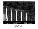
- One embodiment of this method can be used to produce fibers (for example, with a diameter of about 0.1 mm to about 1.0 mm) having a plurality of frayed-end microfibers on their surface.
- a 0.45 mm thick sheet of a thermoplastic polymer such as polyethylene
- the thermoplastic film typically has a plurality of closely spaced deep grooves on both sides of the film, for example, 0.25 mm deep grooves spaced 0.95 mm on center (shown in profile in Fig. 16).
- the reciprocating contact with the abrasive surface can cause the film to split apart at the bottom of the grooves to form individual fibers with a plurality of frayed-end microfibers on their surface.
- Such a process can be used to produce fibers with a diameter of about 01. mm to about 1.0 mm having frayed-end microfibers about 50 to about 500 microns in length on the surface thereof.
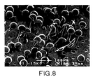
- Polymer surfaces having a plurality of projecting expanded cross-section shaped microfibers may be produced by a method which includes laminating a polymer surface to a resilient template surface having a plurality of undercut-shaped microdepressions. During the lamination process the polymer surface is forced into the microdepressions in the template surface to form a plurality of undercut-shaped microprojections on the polymer surface. If the polymer surface is maintained in a sufficiently softened state while it is delaminated from the template surface, the microprojections can be stretched to form expanded cross-section shaped microfibers on the polymer surface.
- microfibers having one or more expanded portions along their length may be formed.
- a resilient surface with a plurality of partially spherical microdepressions for example, microdepressions formed by removing glass beads from a cured silicone rubber film
- a napped polymer surface having a plurality of expanded-head shaped microfibers can be generated.
- undercut-shaped is defined as a shape having a cross-sectional surface area which increases and then typically decreases along a perpendicular vector away from the polymer surface.
- the cross-sectional surface area is measured in a plane parallel to the major surface of the polymer substrate with respect to which the undercut-shaped microdepression or microprotrusion in question is positioned.
- the interaction between the forming microfibers, which are at least partially solidified, and the resilient template surface is such that the tip portion of the microfibers, which includes an expanded portion, substantially retain their shape as the microstructured polymer film is pulled away from the resilient template surface. To some extent this may be due to some resiliency on the part of the microprotrusions themselves, as where the solidifying polymer material exhibits some degree of elasticity. More typically, this interaction is achieved by the resiliency of the template surface.
- the stem portion of the microfibers closer to the underlying polymer surface is typically cooled at a slower rate than the tip portion such that the stem is pulled and/or stretched to form an elongated stem.
- the temperature of the template surface is typically maintained below the softening point of the polymer material (for example, where the polymer material is a thermoplastic polymer).
- the solidification may be achieved by applying additional heat to the polymer material while the material is in contact with the template surface.
- Expanded cross-section shaped microfibers of the type described above typically have an average maximum cross-sectional dimension of no more than about 200 microns and, preferably of about 25 to about 100 microns.
- the average height of the expanded cross-section shaped microfibers is generally at least about 1.5 times and preferably about 2 to about 5 times the average depth of the microdepressions in the template surface.
- expanded cross-section shaped microfibers generated using a closed cell polyurethane foam as a template surface typically have a maximum width of no more than about 200 microns, preferably, no more than about 100 microns.
- Microfibers of this type typically have an average length of about 50 to about 500 microns.
- the material which forms the resilient template surface typically permits the microstructured polymer film to be separated from the resilient template without substantially destroying the microfibers. This requires that the forming napped film does not adhere to the resilient template surface.
- the resilient template surface may be formed from a number of resilient materials which permit the processed polymer to be removed without problems of adhesion.
- the resilient template surface is formed from a silicone rubber. Resilient template materials formed from a polyurethane or silicone permit the present method to be carried out under a wide range of processing conditions, for example, temperatures from about 0°C to about 400°C or even higher.
- the resilient template surface may include a layer of a porous resilient material, such as a polymer foam.
- suitable foams for the resilient surface include polyurethane foams and silicone foams.
- the foam may be a closed cell polyurethane foam such as LS 1525 polyurethane foam (available from EAR® Specialty Composites Corporation, Indianapolis, IN) or PORON polyurethane foam (available from Rogers Corporation, East Woodstock, CT).
- the closed cell polyurethane foams disclosed in U.S. Patents 3,772,224 and 3,849,156 may also be employed as the resilient template surface.
- Another example of a suitable polymer foam is a closed cell silicone foam such as Bisco BF-1000 foam (available from Bisco Products, Elk Grove, IL).
- the resilient template surface may also be formed from an open cell polymer foam.
- the resilient material which forms the resilient template surface may inherently include microdepressions, for example, the pocket-like depressions present in the surface of a polymer foam.
- the resilient surface may also include a thin outer layer of a non-porous flexible material covering the foam.
- the resilient surface may include a foam layer covered by a thin layer (for example, about 0.5 mm to about 1.0 mm) of silicone rubber.
- the resilient surface may include Silastic® brand J-RTV silicone rubber (commercially available from Dow Coming Corp., Midland, MI).
- a desired pattern and/or shape of microprotrusions in a flexible material may also be generated by embedding a plurality of microscopic particles in the surface of a resilient material, such as by embedding inorganic particles (for example, glass beads) in a silicone rubber layer.
- microdepressions may be formed in a silicone rubber layer (or other nonporous flexible material) by removing microparticles embedded in the silicone rubber to leave a plurality of microdepressions in the rubber surface.
- the microdepressions are typically substantially inverted replicas of the microparticles previously embedded in the template surface.
- Polymer surfaces having a plurality of projecting tapered microfibers are also provided herein. Such surfaces can be produced by laminating a thermoplastic substrate (for example, a film) to a template surface having a release surface with a plurality of microdepressions therein.
- the microdepressions include a non-release surface. In some cases, the entire internal surfaces of the microdepressions may be formed from a non-release material. More typically, however, only the bottom portion of the microdepressions are formed from the non-release material.
- An example of such a template structure is a polyolefin film (for example, a polypropylene film) embossed to have a regular pattern ofmicrodepressions and overcoated with a release material such as a silicone release agent.
- the silicone release agent can be applied to the embossed polyolefin surface so that only the flat land areas and not the internal surfaces within the microdepressions become coated.
- Lamination of a thermoplastic polymer substrate (for example, a film) to the template structure can be carried out to form microprojections on the polymer surface, where each microprojection projects into one of the microdepressions and is bonded to the non-release surface therewithin.
- thermoplastic microprojections on the polymer substrate can be stretched into microfibers prior to debonding of the thermoplastic polymer substrate from the template surface (see Fig. 10).
- the polymer material which makes up the microprojections extending into the microdepressions in the template surface may be stretched and drawn out.
- the microfibers will typically have an average length that is greater than the average depth of the microdepressions in the template surface. Using such a process, generation of microfibers having an average length that is at least about 2.0 times and preferably about 2.5 to about 10 times the average depth of the microdepressions may be achieved.
- microfibers having a tapered profile can be produced. If the process is carried out in a continuous fashion such as where the template surface is the cover of a nip roll and the polymer substrate is a thermoplastic polymer film passing through the nip, tapered microfibers having a curved profile (see, for example, the microfibers on the surface shown in Fig. 13) can be generated.
- the tapered microfibers generated by the methods described herein can have a variety of cross-sections shapes.
- the cross-section of the microdepressions reflects the shape of the microdepressions in the template surface.
- the cross-sectional area of the base of the microfiber is typically close to but no more than the cross-sectional area of the microdepression (for example, about 90 to 100% of the cross-sectional area of the microdepression).
- the amount of taper of a microfiber will depend on the extent to which the microfiber is drawn out; the longer the microfibers for a given template surface, the smaller the tip cross-sectional area (and smaller the half-height cross-sectional area) and the higher the total amount of taper of the microfibers.
- the tapered microfibers disclosed herein typically have an average maximum base cross-section dimension of at least about 25 microns and generally no more that about 200 microns.
- the average length of the tapered microfibers is typically no more that about 2,500 microns and preferably about 300 to about 2,000 microns.
- the amount of taper of the microfibers (two times the ratio of the average base cross-sectional area to the average half-height cross-sectional area) will very as a function of the extent to which the microfibers are drawn out during formation.
- the tapered microfibers commonly have an amount of taper from end to end of about 10 to 1.
- Another method of producing unitary polymer substrates having a plurality of tapered microfibers includes laminating two thermoplastic polymer substrates (for example, films) to opposite sides of a template film having a plurality of microscopic holes therethrough.
- the template film is typically either coated with or formed from a release material such as a silicone rubber.
- the thermoplastic polymer substrates are laminated to the template film so that a plurality of microprotrusions project from each of the thermoplastic polymer substrates into the holes.
- sufficient thermoplastic material is forced into the microscopic holes such that the two polymer substrates are bonded together by the tips of the microprotrusions extending from each of the polymer substrates into the holes in the template film.
- thermoplastic polymer substrates are then delaminated from the template film while maintaining the thermoplastic polymer substrates in a sufficiently softened state to stretch the microprotrusions into microfibers prior to debonding of the thermoplastic polymer substrates from each other.
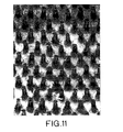
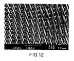
- the result after delamination is the formation of two unitary polymer napped films in which the microprojections have been stretched into microfibers before the polymer substrates debond from each other. Examples of napped polymer surfaces generated using this method are shown in Figures 12 and 13.
- Another method which may be used to produce unitary polymer films includes laminating a carrier film to a nonporous thermoplastic polymer film.
- two unitary polymer films can be produced by a method which includes laminating two carrier films to either side of a non-porous thermoplastic polymer film.
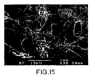
- the two carrier films are then pulled apart while maintaining the thermoplastic film in a sufficiently softened state to pull and stretch a portion of the thermoplastic polymer film into a plurality of high aspect ratio microfibers (for example, microfibers that resemble an extremely thin "angel hair pasta", see, for example, the polymer surface in the electron micrograph shown in Fig. 15) extending from and integral with the portions of the thermoplastic polymer film remaining in contact with the carrier films.
- Structures having this "angel hair" type structure on a surface may be useful in filter applications due to the ability of such a material to efficiently entrap airborne particulates.
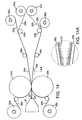
- Fig. 14 illustrates one process suitable for forming angel hair microfibers.
- a thermoplastic polymer film 24 (for example, a polyethylene film) exits the film die 22 of the extruder in a softened state and is laminated to two carrier films 25a, 25b in a nip between chill rolls 23a, 23b. The temperatures of the polymer film 24 exiting the extruder and the chill rolls 23a, 23b is adjusted so that the polymer film 24 is still in a softened state as it exits the nip.
- the two carrier films are separated by means of rollers 29a and 29b as they exit the nip. This causes the softened polymer film to be split into two films.
- the softened center portion of the polymer film is pulled and drawn out into a plurality of high aspect ratio microfibers.
- the forming microfibers cool to a point where the polymer material solidifies.
- Further separation of the carrier films 25a, 25b then causes the microfibers to break, thereby generating two unitary napped films 26a, 26b each having a plurality of projecting high aspect ratio microfibers.
- the carrier films 25a, 25b can be delaminated from the back of the napped polymer films 26a, 26b and rolled up onto respective pick up rolls 30a and 30b.
- Fig. 15 shows an electron micrograph of an exemplary angel hair napped film as described herein.
- the microfibers have an extremely high aspect ratio.
- napped polymer fibers of this type have microfibers with an aspect ratio of at least about 10.
- Such angel hair microfibers typically have a maximum cross-sectional dimension of at least about 10 microns, but no more than about 100 microns, and preferably about 10 to about 50 microns.
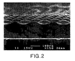
- a 0.16 mm thick film of linear low density polyethylene (available from CT Films, Chippewa, WI under the designation X0-52; XEM 352.1) was structured on one side with features that were square at their base or intersection with the film and raised to a rounded top; the square base was about 75 ⁇ m on a side and the height was about 30 ⁇ m.
- the placement of the features formed a square lattice array about 0.12 mm on a side (see Fig. 2).
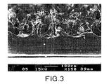
- the structured side of this film was treated with a random orbit palm sander (DeWalt Model DW 421) using 80 grit coated abrasive (80A NO-FIL ADALOX A273 available from Norton, Troy, NY).
- Moderate hand pressure was used on the sander as it was slowly moved back and forth in a reciprocating motion in one direction for about 15 sec and then back and forth in a second direction perpendicular to the first for another 15 sec.
- a section was cut from the center of this sample and examined with a scanning electron microscope. Fibers with frayed tips were formed predominately at each of the raised features and extended to various heights up to about 200 ⁇ m ( Figure 3).
- the XEM 352.1 low density polyethylene was treated as described Example 1 except that a 180 grit coated abrasive was used (P180 255L PRODUCTION RESIN BONDED FRE-CUT FILM OPEN COAT, 3M, St. Paul, MN).
- An electron micrograph of material prepared as per this example is shown in Figure 4.
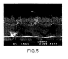
- the XEM 352.1 low density polyethylene was treated as described Example 1 except that a 400 grit coated abrasive was used (P400 SG3 PRODUCTION RESIN BONDED FRE-CUT FILM OPEN COAT, 3M, St. Paul, MN).
- An electron micrograph of material prepared as per this example is shown in Figure 5.
- the fibers formed at the raised features had lengths up to about 100 ⁇ m, were frayed at the ends and were smaller in cross section than fibers formed with the coarser grits in Examples 1 and 2.
- the napped polymer sheet produced in Example 1 was further treated by the same procedure using a finer grit abrasive, that is, after abrading the structural polyethylene surface with 80 grit coated abrasive, as described in Example 1, the resulting napped surface was subsequently treated with 400 grit paper.
- This double treatment that is, abrasion with two different coated abrasives with the second much finer in size than the first, further frayed the ends of the fibers ( Figure 6) and generated microfibrils extending from the microfibers produced with the coarse (80 grit) treatment
Description
Claims (10)
- A method of producing a unitary polymer substrate including a napped surface which comprises a plurality of frayed-end microfibers, the method comprising:reciprocatingly contacting a surface of a thermoplastic polymer substrate with an abrasive surface.
- The method of claim 1 comprising reciprocatingly contacting the thermoplastic polymer surface with an abrasive surface having a grit of 40 to 500.
- The method of claim 1 comprising reciprocatingly contacting the abrasive surface with a thermoplastic polymer surface including a plurality of microprotrusions.
- The method of claim 1 comprising reciprocatingly contacting the thermoplastic polymer surface with a first abrasive surface having a coarse grit to form a first napped surface having a plurality of first frayed-end microfibers projecting therefrom; and reciprocatingly contacting the first napped surface with a second abrasive surface having a finer grit than the first abrasive surface to form a second napped surface having a plurality of second projecting frayed-end microfibers which include a surface with a plurality of microfibrils extending therefrom.
- The method of claim 3 wherein the microprotrusions are ridges.
- The method of claim 3 wherein the microprotrusions have square bases.
- The method of claim 1 wherein the microfibers have an average length of no more than 500 micrometers.
- The method of claim 1 wherein the microfibers have a plurality of microfibrils protruding from a surface of the microfibers.
- The method of claim 1 wherein the polymer surface is first contacted with an abrasive surface having a grit of 40 to 300 and then contacted with an abrasive surface having a grit of 80 to 500 where the difference in grit between the first and second abrasives is at least 50.
- The method of claim 1 wherein the substrate is a fiber.
Applications Claiming Priority (3)
| Application Number | Priority Date | Filing Date | Title |
|---|---|---|---|
| US902172 | 1997-07-29 | ||
| US08/902,172 US6605332B2 (en) | 1997-07-29 | 1997-07-29 | Unitary polymer substrate having napped surface of frayed end microfibers |
| PCT/US1997/021717 WO1999006623A1 (en) | 1997-07-29 | 1997-11-25 | Microstructured polymer substrate |
Publications (2)
| Publication Number | Publication Date |
|---|---|
| EP1002149A1 EP1002149A1 (en) | 2000-05-24 |
| EP1002149B1 true EP1002149B1 (en) | 2004-05-26 |
Family
ID=25415418
Family Applications (1)
| Application Number | Title | Priority Date | Filing Date |
|---|---|---|---|
| EP97948556A Expired - Lifetime EP1002149B1 (en) | 1997-07-29 | 1997-11-25 | Microstructured polymer substrate |
Country Status (6)
| Country | Link |
|---|---|
| US (2) | US6605332B2 (en) |
| EP (1) | EP1002149B1 (en) |
| JP (1) | JP2001512066A (en) |
| AU (1) | AU5460198A (en) |
| DE (1) | DE69729328T2 (en) |
| WO (1) | WO1999006623A1 (en) |
Families Citing this family (47)
| Publication number | Priority date | Publication date | Assignee | Title |
|---|---|---|---|---|
| US6946182B1 (en) | 1999-07-16 | 2005-09-20 | Allgeuer Thomas T | Fringed surface structures obtainable in a compression molding process |
| DE19953039A1 (en) | 1999-11-03 | 2001-05-23 | Hcd Gmbh | Process for the production of a multilayer surface-structured semi-finished product from thermoplastic materials |
| EP1267780A2 (en) | 2000-04-07 | 2003-01-02 | The Procter & Gamble Company | Apertured polymeric film for absorbent articles |
| US6468451B1 (en) | 2000-06-23 | 2002-10-22 | 3M Innovative Properties Company | Method of making a fibrillated article |
| US6872438B1 (en) | 2000-07-17 | 2005-03-29 | Advanced Design Concept Gmbh | Profile or molding having a fringed surface structure |
| US20030211310A1 (en) | 2001-06-21 | 2003-11-13 | Haas Christopher K. | Foam and method of making |
| US20030116499A1 (en) * | 2001-10-05 | 2003-06-26 | Ward Bennett C. | Medium for isolating, detecting, separating, or purifying chemical and biological substances |
| US7815761B2 (en) * | 2001-11-15 | 2010-10-19 | Advanced Label Systems, Inc. | Apparatus and method for applying labels |
| US6692823B2 (en) | 2001-12-19 | 2004-02-17 | 3M Innovative Properties Company | Microfibrillated articles comprising hydrophillic component |
| US6908453B2 (en) * | 2002-01-15 | 2005-06-21 | 3M Innovative Properties Company | Microneedle devices and methods of manufacture |
| CN1691969A (en) | 2002-07-19 | 2005-11-02 | 3M创新有限公司 | Microneedle devices and microneedle delivery apparatus |
| US7713457B2 (en) | 2007-03-22 | 2010-05-11 | Dynasty Footwear, Ltd. | Composite sheet materials and processes for manufacturing same |
| US6755878B2 (en) | 2002-08-02 | 2004-06-29 | 3M Innovative Properties Company | Abrasive articles and methods of making and using the same |
| US20040063368A1 (en) * | 2002-09-26 | 2004-04-01 | Greiff Jerrold Arthur | Micro tracker mouse pad |
| CN1767939B (en) * | 2003-01-30 | 2012-07-04 | 塔克-法斯特系统有限公司 | System and methods of manufacturing hook plates |
| US7086423B2 (en) * | 2003-05-15 | 2006-08-08 | Milliken & Company | Pile fabric |
| US7358282B2 (en) * | 2003-12-05 | 2008-04-15 | Kimberly-Clark Worldwide, Inc. | Low-density, open-cell, soft, flexible, thermoplastic, absorbent foam and method of making foam |
| JP2007523771A (en) * | 2004-02-23 | 2007-08-23 | スリーエム イノベイティブ プロパティズ カンパニー | Microneedle array molding method |
| US20060014462A1 (en) * | 2004-07-16 | 2006-01-19 | Jones William R Iii | Reusable microfiber non-woven cleaning fabric |
| ATE468961T1 (en) | 2004-12-07 | 2010-06-15 | 3M Innovative Properties Co | METHOD FOR SHAPING A MICRONEEDLE |
| US20060166578A1 (en) * | 2005-01-21 | 2006-07-27 | Myers Kasey R | Process for creating fabrics with branched fibrils and such fibrillated fabrics |
| DE602006016279D1 (en) | 2005-06-27 | 2010-09-30 | 3M Innovative Properties Co | MICRO NEEDLE CARTRIDGE ARRANGEMENT |
| US8063264B2 (en) * | 2005-08-26 | 2011-11-22 | Michael Spearman | Hemostatic media |
| FR2892336B1 (en) * | 2005-10-21 | 2009-10-09 | Michelin Soc Tech | MARKING PROVIDES IMPROVED VISIBILITY AND MARKING METHOD. |
| US20080262416A1 (en) * | 2005-11-18 | 2008-10-23 | Duan Daniel C | Microneedle Arrays and Methods of Preparing Same |
| US8158689B2 (en) | 2005-12-22 | 2012-04-17 | Kimberly-Clark Worldwide, Inc. | Hybrid absorbent foam and articles containing it |
| US20070148433A1 (en) * | 2005-12-27 | 2007-06-28 | Mallory Mary F | Elastic laminate made with absorbent foam |
| JP5301446B2 (en) | 2006-10-04 | 2013-09-25 | フォームウェイ ファーニチャー リミテッド | Chair |
| KR100826241B1 (en) | 2007-07-24 | 2008-04-29 | (주)대건씨앤엘 | Composition |
| USD600051S1 (en) | 2008-04-09 | 2009-09-15 | Formway Furniture Limited | Chair back |
| USD604535S1 (en) | 2008-04-09 | 2009-11-24 | Formway Furniture Limited | Chair |
| KR101739242B1 (en) | 2008-07-14 | 2017-05-23 | 애브리 데니슨 코포레이션 | Apparatus and process for cutting adhesive labels |
| CA131020S (en) | 2008-12-12 | 2010-02-03 | Formway Furniture Ltd | Chair |
| DE102009021381A1 (en) * | 2009-05-14 | 2010-11-18 | Tesa Se | Optically detectable adhesive tape with reduced gloss properties |
| US8282667B2 (en) * | 2009-06-05 | 2012-10-09 | Entellus Medical, Inc. | Sinus dilation catheter |
| US8574690B2 (en) * | 2009-12-17 | 2013-11-05 | International Paper Company | Printable substrates with improved dry time and acceptable print density by using monovalent salts |
| US8652593B2 (en) * | 2009-12-17 | 2014-02-18 | International Paper Company | Printable substrates with improved brightness from OBAs in presence of multivalent metal salts |
| EP2679112A1 (en) | 2012-06-26 | 2014-01-01 | 3M Innovative Properties Company | Method for manufacturing fasteners and precursor webs, a fastener and a precursor web |
| DE102013109621B4 (en) * | 2012-11-19 | 2021-02-11 | Karlsruher Institut für Technologie | Process for producing a shaped body with a superhydrophobic surface and shaped body obtainable with this process and its use |
| CN109476075B (en) * | 2016-07-20 | 2021-09-14 | 电化株式会社 | Thermoplastic resin sheet having hair-like bodies and molded article thereof |
| US10155318B2 (en) | 2017-03-16 | 2018-12-18 | Perception Robotics, Inc. | Systems and methods for post-treatment of dry adhesive microstructures |
| EP3641713A1 (en) | 2017-06-22 | 2020-04-29 | The Procter and Gamble Company | Laminate webs and absorbent articles having the same |
| EP3670147B1 (en) * | 2017-09-06 | 2021-10-27 | Denka Company Limited | Resin sheet having capillaceous bodies and molded product thereof |
| CN112533567A (en) | 2018-08-22 | 2021-03-19 | 宝洁公司 | Disposable absorbent article |
| JP7361044B2 (en) * | 2018-11-16 | 2023-10-13 | デンカ株式会社 | Thermoplastic resin sheet with hair-like bodies and molded products thereof |
| CN112262033B (en) * | 2018-12-04 | 2021-11-23 | 电化株式会社 | Resin sheet having hair-like bodies and molded article thereof |
| WO2021209841A1 (en) * | 2020-04-16 | 2021-10-21 | 3M Innovative Properties Company | Flocked film and method of manufacture of thereof |
Family Cites Families (69)
| Publication number | Priority date | Publication date | Assignee | Title |
|---|---|---|---|---|
| US3041193A (en) | 1957-08-29 | 1962-06-26 | Gen Tire & Rubber Co | Method of making suede-like plastic sheeting |
| US3179550A (en) | 1958-07-09 | 1965-04-20 | Friedman Abraham | Pile surfaced product and method of forming same |
| US3055357A (en) | 1959-11-04 | 1962-09-25 | Henry R Redka | Footbath |
| US3027595A (en) | 1959-11-27 | 1962-04-03 | Takai Unokichi | Apparatus and method of continuous molding of a thermoplastic sheet having fine pile-like projections |
| US3142599A (en) | 1959-11-27 | 1964-07-28 | Sealed Air Corp | Method for making laminated cushioning material |
| US3192589A (en) | 1960-07-18 | 1965-07-06 | Raymond C Pearson | Separable fastener |
| US3152002A (en) | 1961-12-11 | 1964-10-06 | American Biltrite Rubber Co | Process of making elastomeric floor or wall covering and step product therefor |
| NL296361A (en) * | 1962-08-13 | 1900-01-01 | ||
| US3312583A (en) | 1963-10-02 | 1967-04-04 | James J Rochlis | Apertured and staggered molded pile product |
| US3266113A (en) | 1963-10-07 | 1966-08-16 | Minnesota Mining & Mfg | Interreacting articles |
| US3325845A (en) * | 1965-02-26 | 1967-06-20 | Int Playtex Corp | Nylon bristle resembling natural bristle |
| US3693851A (en) * | 1965-06-05 | 1972-09-26 | Polymer Processing Res Inst | Method for fibrillating stretched film |
| US3312586A (en) | 1965-10-24 | 1967-04-04 | Barlow Terrence William | Method of making synthetic suede and product thereof |
| US3600260A (en) * | 1966-06-01 | 1971-08-17 | Tatsuo Watanabe | Artificial leather or suede-like material |
| US3524791A (en) * | 1967-07-03 | 1970-08-18 | Du Pont | Man-made suede and method of making same |
| FR1578424A (en) | 1967-08-17 | 1969-08-14 | ||
| US3607493A (en) | 1968-04-12 | 1971-09-21 | Pervel Ind Inc | Method of making a plastic-coated fabric |
| FR2030102A1 (en) * | 1968-12-24 | 1970-10-30 | Kureha Chemical Ind Co Ltd | Artificial skins furs felts etc with fibre - like projections over whole surface |
| US3772224A (en) | 1969-01-31 | 1973-11-13 | Union Carbide Corp | Process for production of a polyurethane foam from a heat curable froth |
| US3849156A (en) | 1969-01-31 | 1974-11-19 | Union Carbide Corp | Process for providing a backing on carpets |
| US3973059A (en) | 1969-09-29 | 1976-08-03 | Brunswick Corporation | Method of making metal flocked fabric |
| CH530187A (en) | 1971-03-26 | 1972-11-15 | Repla Internat S A H | Method of manufacturing a fastening device |
| CS150413B1 (en) * | 1971-04-30 | 1973-09-04 | ||
| GB1399095A (en) * | 1971-06-21 | 1975-06-25 | Ici Ltd | Production of a coloured pile surfaced products |
| US3950582A (en) | 1971-08-05 | 1976-04-13 | Pnc Company | Fibrillated textile structure and process of producing same |
| US3814644A (en) | 1971-09-16 | 1974-06-04 | Pervel Ind Inc | Processing of expanded-plastic sheet material |
| GB1451311A (en) * | 1972-12-04 | 1976-09-29 | Ici Ltd | Apparatus and process for the production of pile surfaced materials |
| GB1491901A (en) * | 1974-02-04 | 1977-11-16 | Ici Ltd | Process for the production of pile surfaced articles |
| US4048269A (en) | 1974-04-08 | 1977-09-13 | Pandel-Bradford, Inc. | Embossed suede material and method of preparing same |
| GB1503669A (en) * | 1974-09-13 | 1978-03-15 | Ici Ltd | Pile surfaced products |
| US4636417A (en) * | 1974-12-10 | 1987-01-13 | Rasmussen O B | Fibrous reticular sheet material |
| US4377544A (en) * | 1974-12-10 | 1983-03-22 | Rasmussen O B | Manufacture of a textile-like reticular product from thermoplastic film |
| US4183889A (en) | 1975-03-22 | 1980-01-15 | Metzeler Schaum Gmbh | Method for the production of a polymer substrate with a fibrous surface |
| US4025678A (en) | 1976-07-09 | 1977-05-24 | Pervel Industries, Inc. | Flocked expanded-plastic fabric and method |
| US4318949A (en) * | 1976-09-16 | 1982-03-09 | Toray Industries, Inc. | Composite nap sheet and process for preparing the same |
| GB1593256A (en) * | 1976-10-07 | 1981-07-15 | Ici Ltd | Pile surface products |
| US4186239A (en) * | 1976-12-06 | 1980-01-29 | Berkley & Company, Inc. | Monofilament weed cutters |
| US4180606A (en) * | 1977-07-25 | 1979-12-25 | M. Lowenstein & Sons, Inc. | Fabrics having flocked corduroy ribs |
| US4331724A (en) * | 1978-05-22 | 1982-05-25 | Milliken Research Corporation | Fibrillated polyester textile materials |
| US4259393A (en) * | 1978-10-02 | 1981-03-31 | Milliken Research Corporation | Fibrillated polyester textile fabric |
| JPS55150325A (en) * | 1979-05-10 | 1980-11-22 | Sanyo Kogyo Kk | Method of surface treatment for plastic sheet |
| IT1114281B (en) * | 1979-05-18 | 1986-01-27 | Montedison Spa | POLYMERIC RETIFORM STRUCTURES EQUIPPED WITH A HIGH SURFACE AREA AS REINFORCEMENT IN HYDRAULIC BINDERS |
| US4316928A (en) * | 1979-11-09 | 1982-02-23 | Milliken Research Corporation | Mechanically surface finished textile material |
| US4440709A (en) * | 1980-03-27 | 1984-04-03 | Rasmussen O B | Method of manufacturing reticular sheet |
| JPS5725926A (en) | 1980-07-23 | 1982-02-10 | Kinugawa Rubber Ind Co Ltd | Surface finish of foamed body |
| US4376147A (en) | 1981-08-31 | 1983-03-08 | Clopay Corporation | Plastic film having a matte finish |
| US4436520A (en) | 1981-12-21 | 1984-03-13 | Exxon Research & Engineering Co. | Low gloss films of enhanced adhesion |
| US4546029A (en) | 1984-06-18 | 1985-10-08 | Clopay Corporation | Random embossed matte plastic film |
| US4778634A (en) * | 1986-08-04 | 1988-10-18 | El Paso Products Company | Process for the manufacture of porous film |
| US4832886A (en) * | 1986-08-04 | 1989-05-23 | El Paso Products Company | Abrasion process for the manufacture of microporous film |
| US4815714A (en) * | 1986-08-04 | 1989-03-28 | El Paso Products Company | Process for the manufacture of microporous film |
| US5032122A (en) | 1987-04-24 | 1991-07-16 | The Procter & Gamble Company | Loop fastening material for fastening device and method of making same |
| GB8806949D0 (en) | 1988-03-23 | 1988-04-27 | Knight C G F | Cleaning products |
| US5230851A (en) | 1989-01-31 | 1993-07-27 | The Procter & Gamble Company | Process of manufacturing a refastenable mechanical fastening system |
| US5116563A (en) | 1990-06-28 | 1992-05-26 | The Procter & Gamble Company | Process for producing a mechanical fastener |
| US5679302A (en) | 1990-09-21 | 1997-10-21 | Minnesota Mining And Manufacturing Company | Method for making a mushroom-type hook strip for a mechanical fastener |
| US5097570A (en) | 1991-01-23 | 1992-03-24 | Bruce Gershenson | Fastening system |
| JP2985325B2 (en) * | 1991-02-18 | 1999-11-29 | 三菱瓦斯化学株式会社 | Manufacturing method of thin copper-clad circuit board |
| US5403478A (en) | 1991-05-15 | 1995-04-04 | Brinkley; Herman E. | Oil-based fluid absorbent article |
| CZ279893A3 (en) | 1991-06-21 | 1996-01-17 | Procter & Gamble | Process for producing a mechanical connecting system with azimuthally inclined points for repeated clamping by means of silk-screen printing |
| US5273805A (en) | 1991-08-05 | 1993-12-28 | Minnesota Mining And Manufacturing Company | Structured flexible carrier web with recess areas bearing a layer of silicone on predetermined surfaces |
| DE69207779T2 (en) * | 1991-11-12 | 1996-05-30 | Minnesota Mining & Mfg | DERIVATIVES OF FLUOROALIPHATIC DIMERIC ACIDS AND THEIR USE |
| US5416958A (en) | 1992-01-21 | 1995-05-23 | Basf Corporation | Easy nap textile fabric and process for making |
| DE69316700T2 (en) | 1992-10-13 | 1998-08-27 | Kuraray Co | Tapered end fiber and pile fabric made from it |
| EP0675797B1 (en) * | 1992-12-23 | 1997-07-16 | United Technologies Corporation | Method for manufacturing composite articles having enhanced exterior surface finishes |
| US5403884A (en) | 1993-01-13 | 1995-04-04 | National Starch And Chemical Investment Holding Corporation | Process for flocking EDPM substrates |
| JPH07314616A (en) * | 1994-05-23 | 1995-12-05 | Sekisui Chem Co Ltd | Surface finish method of resin panel |
| JP3519160B2 (en) * | 1995-03-15 | 2004-04-12 | 三菱製紙株式会社 | Resin-coated photographic support, cooling roll used therefor, and surface processing method thereof |
| JPH09121902A (en) * | 1995-08-29 | 1997-05-13 | Hiroshima Kasei Ltd | Sueded material for shoe sole and manufacture of sueded material |
-
1997
- 1997-07-29 US US08/902,172 patent/US6605332B2/en not_active Expired - Fee Related
- 1997-11-25 JP JP2000505358A patent/JP2001512066A/en active Pending
- 1997-11-25 EP EP97948556A patent/EP1002149B1/en not_active Expired - Lifetime
- 1997-11-25 WO PCT/US1997/021717 patent/WO1999006623A1/en active IP Right Grant
- 1997-11-25 AU AU54601/98A patent/AU5460198A/en not_active Abandoned
- 1997-11-25 DE DE1997629328 patent/DE69729328T2/en not_active Expired - Lifetime
-
2003
- 2003-06-20 US US10/600,966 patent/US7070727B2/en not_active Expired - Fee Related
Also Published As
| Publication number | Publication date |
|---|---|
| US20040005434A1 (en) | 2004-01-08 |
| US6605332B2 (en) | 2003-08-12 |
| US7070727B2 (en) | 2006-07-04 |
| DE69729328D1 (en) | 2004-07-01 |
| AU5460198A (en) | 1999-02-22 |
| EP1002149A1 (en) | 2000-05-24 |
| US20010036529A1 (en) | 2001-11-01 |
| DE69729328T2 (en) | 2005-06-02 |
| JP2001512066A (en) | 2001-08-21 |
| WO1999006623A1 (en) | 1999-02-11 |
Similar Documents
| Publication | Publication Date | Title |
|---|---|---|
| EP1002149B1 (en) | Microstructured polymer substrate | |
| US7238314B2 (en) | Polymer transfer apparatus, methods, and composite webs | |
| US4422837A (en) | Apparatus for converting thermoplastic film into an open-work sheet | |
| US6054091A (en) | J hook-type hook strip for a mechanical fastener | |
| US4859519A (en) | Method and apparatus for preparing textured apertured film | |
| US7037457B2 (en) | Systems and methods for composite webs with structured discrete polymeric regions | |
| US4636417A (en) | Fibrous reticular sheet material | |
| AU724679B2 (en) | Superimposed embossing of capped stem mechanical fastener structures | |
| US3557407A (en) | Apparatus for surface forming sheet material | |
| US6982055B2 (en) | Multiheaded hook | |
| EP1011361B1 (en) | Method and apparatus for forming headed stem mechanical fastener structures | |
| US7669297B2 (en) | Composite webs and closure systems | |
| JP2011092744A (en) | Heat treated profile extruded hook | |
| US20030087059A1 (en) | Composite webs with discrete elastic polymeric regions | |
| US6136405A (en) | Sheet material having a fibrous surface and method of making the same | |
| EP0998208B1 (en) | Stretched fasteners | |
| MXPA99011460A (en) | Superimposed embossing of capped stem mechanical fastener structures | |
| WO1984003723A1 (en) | Textile-like reticular product derived from film material | |
| JP2002336011A (en) | Female engaging surface fastener having backing and method for manufacturing the same |
Legal Events
| Date | Code | Title | Description |
|---|---|---|---|
| PUAI | Public reference made under article 153(3) epc to a published international application that has entered the european phase |
Free format text: ORIGINAL CODE: 0009012 |
|
| 17P | Request for examination filed |
Effective date: 20000114 |
|
| AK | Designated contracting states |
Kind code of ref document: A1 Designated state(s): DE FR GB IT |
|
| 17Q | First examination report despatched |
Effective date: 20010905 |
|
| GRAP | Despatch of communication of intention to grant a patent |
Free format text: ORIGINAL CODE: EPIDOSNIGR1 |
|
| GRAS | Grant fee paid |
Free format text: ORIGINAL CODE: EPIDOSNIGR3 |
|
| GRAA | (expected) grant |
Free format text: ORIGINAL CODE: 0009210 |
|
| AK | Designated contracting states |
Kind code of ref document: B1 Designated state(s): DE FR GB IT |
|
| REG | Reference to a national code |
Ref country code: GB Ref legal event code: FG4D |
|
| REF | Corresponds to: |
Ref document number: 69729328 Country of ref document: DE Date of ref document: 20040701 Kind code of ref document: P |
|
| ET | Fr: translation filed | ||
| PLBE | No opposition filed within time limit |
Free format text: ORIGINAL CODE: 0009261 |
|
| STAA | Information on the status of an ep patent application or granted ep patent |
Free format text: STATUS: NO OPPOSITION FILED WITHIN TIME LIMIT |
|
| 26N | No opposition filed |
Effective date: 20050301 |
|
| PGFP | Annual fee paid to national office [announced via postgrant information from national office to epo] |
Ref country code: IT Payment date: 20061130 Year of fee payment: 10 |
|
| PGFP | Annual fee paid to national office [announced via postgrant information from national office to epo] |
Ref country code: FR Payment date: 20071119 Year of fee payment: 11 |
|
| PG25 | Lapsed in a contracting state [announced via postgrant information from national office to epo] |
Ref country code: IT Free format text: LAPSE BECAUSE OF NON-PAYMENT OF DUE FEES Effective date: 20071125 |
|
| REG | Reference to a national code |
Ref country code: FR Ref legal event code: ST Effective date: 20090731 |
|
| PGFP | Annual fee paid to national office [announced via postgrant information from national office to epo] |
Ref country code: DE Payment date: 20091127 Year of fee payment: 13 |
|
| PGFP | Annual fee paid to national office [announced via postgrant information from national office to epo] |
Ref country code: GB Payment date: 20091125 Year of fee payment: 13 |
|
| GBPC | Gb: european patent ceased through non-payment of renewal fee |
Effective date: 20101125 |
|
| REG | Reference to a national code |
Ref country code: DE Ref legal event code: R119 Ref document number: 69729328 Country of ref document: DE Effective date: 20110601 Ref country code: DE Ref legal event code: R119 Ref document number: 69729328 Country of ref document: DE Effective date: 20110531 |
|
| PG25 | Lapsed in a contracting state [announced via postgrant information from national office to epo] |
Ref country code: FR Free format text: LAPSE BECAUSE OF NON-PAYMENT OF DUE FEES Effective date: 20081130 |
|
| PG25 | Lapsed in a contracting state [announced via postgrant information from national office to epo] |
Ref country code: GB Free format text: LAPSE BECAUSE OF NON-PAYMENT OF DUE FEES Effective date: 20101125 |
|
| PG25 | Lapsed in a contracting state [announced via postgrant information from national office to epo] |
Ref country code: DE Free format text: LAPSE BECAUSE OF NON-PAYMENT OF DUE FEES Effective date: 20110531 |