EP0998978A2 - Universal outlet for filter units - Google Patents
Universal outlet for filter units Download PDFInfo
- Publication number
- EP0998978A2 EP0998978A2 EP99119694A EP99119694A EP0998978A2 EP 0998978 A2 EP0998978 A2 EP 0998978A2 EP 99119694 A EP99119694 A EP 99119694A EP 99119694 A EP99119694 A EP 99119694A EP 0998978 A2 EP0998978 A2 EP 0998978A2
- Authority
- EP
- European Patent Office
- Prior art keywords
- section
- inlet
- outlet
- housing
- filter
- Prior art date
- Legal status (The legal status is an assumption and is not a legal conclusion. Google has not performed a legal analysis and makes no representation as to the accuracy of the status listed.)
- Granted
Links
- 239000012530 fluid Substances 0.000 claims abstract description 24
- 238000001914 filtration Methods 0.000 claims description 13
- 238000004891 communication Methods 0.000 claims description 6
- 239000000706 filtrate Substances 0.000 claims description 6
- 238000000034 method Methods 0.000 claims 2
- 238000004128 high performance liquid chromatography Methods 0.000 description 5
- 238000004458 analytical method Methods 0.000 description 3
- 238000000465 moulding Methods 0.000 description 2
- -1 polyethylene Polymers 0.000 description 2
- 239000000243 solution Substances 0.000 description 2
- 239000004698 Polyethylene Substances 0.000 description 1
- 239000004743 Polypropylene Substances 0.000 description 1
- 230000000274 adsorptive effect Effects 0.000 description 1
- 230000006835 compression Effects 0.000 description 1
- 238000007906 compression Methods 0.000 description 1
- 238000010276 construction Methods 0.000 description 1
- 238000002347 injection Methods 0.000 description 1
- 239000007924 injection Substances 0.000 description 1
- 239000007788 liquid Substances 0.000 description 1
- 238000004519 manufacturing process Methods 0.000 description 1
- 239000000463 material Substances 0.000 description 1
- 239000012528 membrane Substances 0.000 description 1
- 239000002245 particle Substances 0.000 description 1
- 229920000573 polyethylene Polymers 0.000 description 1
- 229920000098 polyolefin Polymers 0.000 description 1
- 229920001155 polypropylene Polymers 0.000 description 1
- 238000002360 preparation method Methods 0.000 description 1
- 238000000926 separation method Methods 0.000 description 1
- 229910001220 stainless steel Inorganic materials 0.000 description 1
- 239000010935 stainless steel Substances 0.000 description 1
- 239000012815 thermoplastic material Substances 0.000 description 1
- 238000000108 ultra-filtration Methods 0.000 description 1
Images


Classifications
-
- A—HUMAN NECESSITIES
- A61—MEDICAL OR VETERINARY SCIENCE; HYGIENE
- A61M—DEVICES FOR INTRODUCING MEDIA INTO, OR ONTO, THE BODY; DEVICES FOR TRANSDUCING BODY MEDIA OR FOR TAKING MEDIA FROM THE BODY; DEVICES FOR PRODUCING OR ENDING SLEEP OR STUPOR
- A61M5/00—Devices for bringing media into the body in a subcutaneous, intra-vascular or intramuscular way; Accessories therefor, e.g. filling or cleaning devices, arm-rests
- A61M5/178—Syringes
- A61M5/31—Details
- A61M5/3145—Filters incorporated in syringes
-
- B—PERFORMING OPERATIONS; TRANSPORTING
- B01—PHYSICAL OR CHEMICAL PROCESSES OR APPARATUS IN GENERAL
- B01D—SEPARATION
- B01D35/00—Filtering devices having features not specifically covered by groups B01D24/00 - B01D33/00, or for applications not specifically covered by groups B01D24/00 - B01D33/00; Auxiliary devices for filtration; Filter housing constructions
-
- A—HUMAN NECESSITIES
- A61—MEDICAL OR VETERINARY SCIENCE; HYGIENE
- A61M—DEVICES FOR INTRODUCING MEDIA INTO, OR ONTO, THE BODY; DEVICES FOR TRANSDUCING BODY MEDIA OR FOR TAKING MEDIA FROM THE BODY; DEVICES FOR PRODUCING OR ENDING SLEEP OR STUPOR
- A61M5/00—Devices for bringing media into the body in a subcutaneous, intra-vascular or intramuscular way; Accessories therefor, e.g. filling or cleaning devices, arm-rests
- A61M5/178—Syringes
- A61M5/31—Details
- A61M5/32—Needles; Details of needles pertaining to their connection with syringe or hub; Accessories for bringing the needle into, or holding the needle on, the body; Devices for protection of needles
- A61M5/34—Constructions for connecting the needle, e.g. to syringe nozzle or needle hub
- A61M5/347—Constructions for connecting the needle, e.g. to syringe nozzle or needle hub rotatable, e.g. bayonet or screw
-
- B—PERFORMING OPERATIONS; TRANSPORTING
- B01—PHYSICAL OR CHEMICAL PROCESSES OR APPARATUS IN GENERAL
- B01D—SEPARATION
- B01D2201/00—Details relating to filtering apparatus
- B01D2201/40—Special measures for connecting different parts of the filter
- B01D2201/4015—Bayonet connecting means
-
- G—PHYSICS
- G01—MEASURING; TESTING
- G01N—INVESTIGATING OR ANALYSING MATERIALS BY DETERMINING THEIR CHEMICAL OR PHYSICAL PROPERTIES
- G01N1/00—Sampling; Preparing specimens for investigation
- G01N1/02—Devices for withdrawing samples
- G01N1/22—Devices for withdrawing samples in the gaseous state
- G01N1/2202—Devices for withdrawing samples in the gaseous state involving separation of sample components during sampling
- G01N1/2205—Devices for withdrawing samples in the gaseous state involving separation of sample components during sampling with filters
-
- G—PHYSICS
- G01—MEASURING; TESTING
- G01N—INVESTIGATING OR ANALYSING MATERIALS BY DETERMINING THEIR CHEMICAL OR PHYSICAL PROPERTIES
- G01N1/00—Sampling; Preparing specimens for investigation
- G01N1/28—Preparing specimens for investigation including physical details of (bio-)chemical methods covered elsewhere, e.g. G01N33/50, C12Q
- G01N1/40—Concentrating samples
- G01N1/4077—Concentrating samples by other techniques involving separation of suspended solids
-
- G—PHYSICS
- G01—MEASURING; TESTING
- G01N—INVESTIGATING OR ANALYSING MATERIALS BY DETERMINING THEIR CHEMICAL OR PHYSICAL PROPERTIES
- G01N1/00—Sampling; Preparing specimens for investigation
- G01N1/02—Devices for withdrawing samples
- G01N1/10—Devices for withdrawing samples in the liquid or fluent state
- G01N1/14—Suction devices, e.g. pumps; Ejector devices
- G01N2001/1418—Depression, aspiration
- G01N2001/1427—Positive displacement, piston, peristaltic
-
- G—PHYSICS
- G01—MEASURING; TESTING
- G01N—INVESTIGATING OR ANALYSING MATERIALS BY DETERMINING THEIR CHEMICAL OR PHYSICAL PROPERTIES
- G01N1/00—Sampling; Preparing specimens for investigation
- G01N1/02—Devices for withdrawing samples
- G01N1/22—Devices for withdrawing samples in the gaseous state
- G01N1/24—Suction devices
- G01N2001/247—Syringes
-
- Y—GENERAL TAGGING OF NEW TECHNOLOGICAL DEVELOPMENTS; GENERAL TAGGING OF CROSS-SECTIONAL TECHNOLOGIES SPANNING OVER SEVERAL SECTIONS OF THE IPC; TECHNICAL SUBJECTS COVERED BY FORMER USPC CROSS-REFERENCE ART COLLECTIONS [XRACs] AND DIGESTS
- Y10—TECHNICAL SUBJECTS COVERED BY FORMER USPC
- Y10S—TECHNICAL SUBJECTS COVERED BY FORMER USPC CROSS-REFERENCE ART COLLECTIONS [XRACs] AND DIGESTS
- Y10S604/00—Surgery
- Y10S604/905—Aseptic connectors or couplings, e.g. frangible, piercable
Definitions
- Filtration of solutions is generally desired to remove particles in sample preparation applications, analytical techniques and prior to an instrumentation analysis, for example, or to sterilize a solution in tissue culture applications.
- different syringe driven filter sizes identified by their filter diameter, are available. These include 4 mm, 13 mm and 25 mm sizes.
- the 4 mm syringe driven filters are typically recommended for the filtration of volumes less than or equal to 1 ml.
- Conventional syringe drive filters have male and female luer taper fittings designed to mechanically connect two medical devices such as a syringe and a needle.
- most conventional syringe driven filters have a female luer lock inlet and male luer slip outlet.
- the female luer lock inlet ensures that the filter is securely (but removably) attached to the outlet of the syringe so as to prevent leakage and loss of sample while filtration takes place. This is especially critical when low sample volumes are being filtered.
- the lock is conventional and includes outer annular wings designed to be removably engaged (by twisting) in corresponding thread-like ribs in the outlet portion of the syringe.
- the internal diameter of the female luer is standardized, according to ANSI specifications, to receive a corresponding standardized male luer such as on a syringe. This standardization ensures that the male and female portions will properly mate.
- a friction fit (“luer slip") can be used, especially in low-pressure applications.
- the male luer slip outlet on the syringe driven filter device allows, for example, a needle to be attached to the outlet of the filter and facilitates a direct injection of a filtered sample into an HPLC (high pressure liquid chromatography) instrument, for autosampler vials or other receptacle for further analysis.
- HPLC high pressure liquid chromatography
- FIG. 2 Another conventional syringe driven filter device is illustrated in Figure 2.
- This device includes a narrowed outlet or "recorder taper" used in place of the male luer slip of the device of Figure 1.
- the recorder taper is narrower than the male luer slip, and thus does not function as a luer (i.e., it does not allow for a friction-fit engagement with a standardized female luer).
- the recorder taper facilitates filtration into small receiving vessels such as HPLC autosampler vials, vial inserts and the wells of microtitre plates.
- the smaller outlet further minimizes the potential of the filtered sample becoming lodged ("airlocked") through capillary action in the top of the narrow receiving vessel such as an autosampler insert, as the air caught beneath the sample cannot escape to allow the sample to flow to the bottom of the vessel.
- An additional feature of this design is a very small downstream (internal volume after the membrane) volume attributed to a smaller internal diameter in the outlet. This can be especially important with small sample volumes.
- FIG. 3 A still further conventional design is shown in Figure 3.
- This design is a 4 mm syringe driven filter with a "tube tip” or “tube outlet”.
- a short tube is inserted into the outlet orifice of the standard male luer slip design in order to facilitate the filtration into a small receiving vessel.
- this design suffers from the drawback of having a larger downstream volume by virtue of the length of the tube tip, which is undesirable with small sample volumes.
- the present invention provides a filter device comprising a filter housing, a filter disposed in the filter housing, an inlet, and an opposed outlet spaced from the inlet, wherein the outlet comprises an extension from the housing, the extension extending longitudinally in the direction of fluid flow and comprising at least a first section having a minimum outer diameter and a second section downstream from the first section and having a terminal end having a maximum outer diameter, the maximum diameter of the second section terminal end being smaller than the minimum diameter of the first section.
- the filter device is syringe driven
- the inlet is a female luer section
- the first section of the outlet comprises a shortened male luer section.
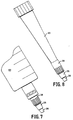
- FIG. 4 there is shown a 4 mm syringe drive filter unit 10 in accordance with one embodiment of the present invention.
- the device 10 includes an inlet end 12 and an outlet end 14 longitudinally spaced from the inlet end 12 in the direction of fluid flow through the device.
- the inlet end 12 comprises an aperture or opening 30 ( Figure 6) providing fluid communication into the filter device housing.
- the inlet end 12 comprises a female luer section designed in accordance with conventional ANSI specifications.
- a centrally located bore 35 is provided to allow fluid communication between the device 10 and another device containing the sample to be filtered that is to be attached to the female luer in a leakproof manner, such as a syringe 60 ( Figure 7).
- the female luer include means to effectuate a luer lock, such as outer annular protrusions 15 which are configured to screw into corresponding thread-like ribs in a male luer lock of the syringe 60 or the like.
- the luer lock prevents both axial and rotational movement of the filter device 10 with respect to the attached device, once engaged.
- a friction or slip fit is often suitable, such as in connection with the terminal end of a pipette tip 65 as shown in Figure 8.
- the 4 mm version of the syringe driven filter device 10 is shown by way of example, and that smaller and larger devices, such as 13 mm, 25 mm and 50 mm filters, are within the scope of the present invention.
- the housing 20 configuration changes (e.g., can be disc shaped rather than cylindrical as in the 4 mm embodiment) in order to accommodate the larger filter, the inlet 12 portion and outlet 14 portion are the same.
- a plurality of nubs, grooves, ridges 23 or the like designed to assist the user in handling the filter unit 10.
- spaced projections, wings or surface textures could be used to provide the same function.
- the outlet 14 portion of the device 10 comprises an extension 50 extending longitudinally from the housing in the direction of fluid flow.
- the extension 50 comprises at least a first section 25 in fluid communication with the housing 20 through the filter and underdrain, the first section 25 having a certain minimum outside diameter.
- the outside diameter of the first section 25 can vary along its length, the minimum outside diameter referred to herein is that portion of the section 25 having the smallest outside diameter.
- the extension 50 also comprises a second section 26 in fluid communication with the first section 25 and extending in the longitudinally in the direction of fluid flow. In the embodiment shown, the second section 26 extends axially directly from the first section 25 and is contiguous thereto.
- the second section 26 has a terminal end 47 having a maximum outside diameter that is smaller than the minimum outside diameter of the first section 25.
- shoulder 27 is formed between first section 25 and second section 26 to define a stepped configuration.
- the second section 26 is tapered so that it narrows in diameter towards its free terminal end 47. This taper assists in the molding operation during manufacture.
- the second section 26 has a length of about 3.3 mm and the free terminal end 47 thereof a diameter of about 3.16 mm. If the second section extends too far in the longitudinal axial direction, an insufficient amount of the first section 25, when in the configuration of a male luer, may be available for engagement with a female luer fitting of a receptacle such as a needle, preventing a secure fit.
- the first section 25 is barbed so as to engage a suitable receptacle, or is configured to form a slip fit with the inlet of a pipette tip 65, for example, as shown in Figure 9.
- the second section 26 could be barbed, or could be configured to form a slip fit with the inlet of a pipette tip 65 as shown in Figure 10.
- the filter units of the present invention are generally disposable, they are preferably constructed of an inexpensive thermoplastic material such as a polyolefin, preferably polyethylene or polypropylene. Those skilled in the art will appreciate that other materials of construction are suitable, such as stainless steel, where the economics so allow. A conventional molding operation can be used to form the units, which are preferably one integral piece.
- the foregoing embodiments utilize generally cylindrical configurations, but that other shapes are within the scope of the present invention.
- the inlet and/or the first and/or second sections could have polygonal cross-section, in which case the limitations discussed above with respect to the dimensions of the outside diameters would instead apply to the outside perimeters.
Landscapes
- Health & Medical Sciences (AREA)
- Hematology (AREA)
- Vascular Medicine (AREA)
- Animal Behavior & Ethology (AREA)
- General Health & Medical Sciences (AREA)
- Anesthesiology (AREA)
- Biomedical Technology (AREA)
- Heart & Thoracic Surgery (AREA)
- Chemical & Material Sciences (AREA)
- Life Sciences & Earth Sciences (AREA)
- Chemical Kinetics & Catalysis (AREA)
- Engineering & Computer Science (AREA)
- Public Health (AREA)
- Veterinary Medicine (AREA)
- Sampling And Sample Adjustment (AREA)
- Filtration Of Liquid (AREA)
- Devices For Use In Laboratory Experiments (AREA)
- Apparatus Associated With Microorganisms And Enzymes (AREA)
- Filtering Of Dispersed Particles In Gases (AREA)
Abstract
Description
Claims (13)
- A filter unit for filtering a sample, comprising a housing for a filter having an inlet, an outlet spaced from said inlet, and a fluid passageway extending therethrough, said outlet comprising an extension extending longitudinally from said housing in the direction of fluid flow, said extension comprising at least a first section having a minimum outer diameter, and a second section downstream from said first section in the direction of fluid flow and having a terminal end having a maximum outer diameter, said maximum outer diameter of said terminal end being smaller than said minimum outer diameter of said first section.
- The filter unit of claim 1, wherein said housing has a filter having a diameter selected from the group consisting of 4 mm, 13 mm, 25 mm and 50 mm.
- The filter unit of claim 1, wherein said inlet comprises a female luer section.
- The filter unit of claim 1, wherein said first section of said extension comprises a male luer section.
- The filter unit of claim 1, wherein said first section of said extension is barbed.
- The filter unit of claim 1, wherein said sample to be filtered is housed in a pipette having a terminal pipette tip, and wherein said inlet is configured to form a slip fit with said terminal pipette tip.
- The filter unit of claim 1, wherein filtrate resulting from filtration of said sample is expelled out said outlet into a container comprising a pipette having a pipette inlet, and wherein said first section of said outlet is configured to form a slip fit with said pipette inlet.
- The filter unit of claim 1, wherein filtrate resulting from filtration of said sample is expelled out said outlet into a container comprising a pipette having a pipette inlet, and wherein said second section of said outlet is configured to form a slip fit with said pipette inlet.
- A filtration device, comprising a housing having filter means supported therein, a fluid inlet to said housing, and a fluid outlet from said housing; said fluid outlet comprising a male luer section having a first axial bore in fluid communication with said housing and having a minimum outside diameter, and a tip portion extending axially from said male luer section, said tip portion having a second axial bore in fluid communication with said first axial bore, said tip portion having an outside diameter smaller than said minimum outside diameter of said male luer section.
- The filtration device of claim 9, wherein said fluid inlet comprises a female luer section.
- A method of filtering a sample, comprising:providing a container for said sample, said container comprising a first male luer section;providing a filter device comprising a housing having a filter, an inlet, an outlet spaced from said inlet, and a fluid passageway extending therethrough, said inlet comprising a female luer section adapted to be removably secured to said first male luer section of said container in a leakproof manner, said outlet comprising a second male luer section having a minimum outside diameter and a tip portion extending axially from said second male luer section and having a terminal end, said terminal end of said tip portion being smaller in outside diameter than said minimum outside diameter of said second male luer section;providing a receptacle for filtrate;placing said terminal end of said tip portion in said receptacle; andcausing said sample to flow from said container into said housing so as to be filtered by said filter and form a filtrate, said filtrate flowing through said second male luer section and said tip portion into said receptacle.
- The method of claim 11, wherein said container is a syringe.
- A filter unit for filtering a sample, comprising a housing for a filter having an inlet, an outlet spaced from said inlet, and a fluid passageway extending therethrough, said outlet comprising an extension extending longitudinally from said housing in the direction of fluid flow, said extension comprising at least a first section having a minimum outer perimeter, and a second section downstream from said first section in the direction of fluid flow and having a terminal end having a maximum outer perimeter, said maximum outer perimeter of said terminal end being smaller than said minimum outer perimeter of said first section.
Applications Claiming Priority (2)
| Application Number | Priority Date | Filing Date | Title |
|---|---|---|---|
| US187717 | 1998-11-06 | ||
| US09/187,717 US6319236B1 (en) | 1998-11-06 | 1998-11-06 | Universal outlet for filter units |
Publications (3)
| Publication Number | Publication Date |
|---|---|
| EP0998978A2 true EP0998978A2 (en) | 2000-05-10 |
| EP0998978A3 EP0998978A3 (en) | 2000-10-04 |
| EP0998978B1 EP0998978B1 (en) | 2004-08-18 |
Family
ID=22690177
Family Applications (1)
| Application Number | Title | Priority Date | Filing Date |
|---|---|---|---|
| EP99119694A Expired - Lifetime EP0998978B1 (en) | 1998-11-06 | 1999-10-05 | Universal outlet for filter units |
Country Status (4)
| Country | Link |
|---|---|
| US (2) | US6319236B1 (en) |
| EP (1) | EP0998978B1 (en) |
| JP (1) | JP3527153B2 (en) |
| DE (1) | DE69919485T2 (en) |
Cited By (2)
| Publication number | Priority date | Publication date | Assignee | Title |
|---|---|---|---|---|
| EP1281377A2 (en) * | 2001-08-03 | 2003-02-05 | Circuit Tree Medical, Inc. | Surgical flow restrictor and filter |
| EP1360968A1 (en) * | 2002-05-06 | 2003-11-12 | Rolf Rainer Scheu | Injection system |
Families Citing this family (13)
| Publication number | Priority date | Publication date | Assignee | Title |
|---|---|---|---|---|
| US6270730B1 (en) * | 1998-06-16 | 2001-08-07 | Northwest Engineering Inc. | Multi-well rotary synthesizer |
| WO2002066100A2 (en) * | 2001-02-20 | 2002-08-29 | Medrad, Inc. | Syringes, connectors, and syringe and connector systems for use in fluid delivery systems |
| US20020182118A1 (en) * | 2001-05-31 | 2002-12-05 | Perry Brian A. | Vacuum manifold for both multi-well plate and individual columns |
| US7319984B2 (en) * | 2004-04-20 | 2008-01-15 | Goldman Sachs & Co. | Method and apparatus for creating and administering a publicly traded interest in a commodity pool |
| DE102004050466A1 (en) * | 2004-10-16 | 2006-04-20 | Olympus Diagnostica Lab Automation Gmbh | Device for pipetting |
| FR2882273B1 (en) * | 2005-02-18 | 2007-06-01 | Gilson Sas Soc Par Actions Sim | TIP FOR TAKING PIPETTE, AND PIPETTE THUS EQUIPPED |
| JP5385304B2 (en) * | 2008-01-09 | 2014-01-08 | スクリーンセル | Apparatus and method for separating and culturing living cells on a filter or extracting genetic material of the cells |
| US8057095B2 (en) | 2009-04-23 | 2011-11-15 | Medtronic, Inc. | Multiple use temperature monitor adapter, system and method of using same |
| CN106975117A (en) | 2011-09-21 | 2017-07-25 | 拜耳医药保健有限责任公司 | Continuous multiple fluid pump device, driving and actuating system and method |
| US9358364B2 (en) * | 2011-10-06 | 2016-06-07 | Becton, Dickinson And Company | Activator attachment for blood control catheters |
| JP6207815B2 (en) | 2012-06-29 | 2017-10-04 | 株式会社日立ハイテクノロジーズ | Filtering member and filtering method |
| KR101243396B1 (en) | 2012-10-22 | 2013-03-13 | 김영환 | Filter cap for syringe |
| JP6749918B2 (en) | 2015-01-09 | 2020-09-02 | バイエル・ヘルスケア・エルエルシーBayer HealthCare LLC | Multi-fluid delivery system with multi-use disposable set and features thereof |
Citations (4)
| Publication number | Priority date | Publication date | Assignee | Title |
|---|---|---|---|---|
| US2857913A (en) * | 1957-04-03 | 1958-10-28 | Pfizer & Co C | Hypodermic needle assembly |
| US3882026A (en) * | 1972-08-14 | 1975-05-06 | American Hospital Supply Corp | Hydrophobic filter device for medical liquids |
| US4127131A (en) * | 1977-06-20 | 1978-11-28 | Johnson & Johnson | Hub assembly for use in the filtration of fluids and method of making the same |
| EP0494779A1 (en) * | 1991-01-09 | 1992-07-15 | Becton, Dickinson and Company | A flashback plug |
Family Cites Families (35)
| Publication number | Priority date | Publication date | Assignee | Title |
|---|---|---|---|---|
| US3402714A (en) | 1967-02-03 | 1968-09-24 | Brunswick Corp | Syringe adapter |
| GB1199498A (en) * | 1967-03-29 | 1970-07-22 | Latex Products Proprietary Ltd | Non-Return Valve for Medical Uses. |
| US3978857A (en) * | 1972-08-14 | 1976-09-07 | American Hospital Supply Corporation | System with filter for administrating parenteral liquids |
| US4043335A (en) * | 1975-08-23 | 1977-08-23 | Soji Ishikawa | Needle holder device of medical administrating injector |
| US4061143A (en) * | 1976-06-10 | 1977-12-06 | Soji Ishikawa | Medical administering needle assembly with filter means |
| US4198974A (en) | 1978-11-09 | 1980-04-22 | Baxter Travenol Laboratories, Inc. | Combination stopper for use in medical and chemical sampling or testing |
| US4296949A (en) * | 1979-08-06 | 1981-10-27 | Abbott Laboratories | Rotatable connecting device for I.V. administration set |
| US4597758A (en) | 1982-09-21 | 1986-07-01 | Baxter Travenol Laboratories, Inc. | Sealing closure for a Luer fitting in open communication with a pressurized liquid supply |
| WO1987001329A1 (en) | 1985-08-28 | 1987-03-12 | Baxter Travenol Laboratories, Inc. | Two-material molding process and device |
| US4732672A (en) | 1987-03-26 | 1988-03-22 | Kiang Chih Hen | Universally applicable mounting apparatus for high pressure liquid chromatography columns |
| US5066287A (en) | 1988-07-27 | 1991-11-19 | Ryan Medical, Inc. | Safety multiple sample rear adapter assembly |
| US5037544A (en) | 1988-06-17 | 1991-08-06 | Snyder Thomas A | Keyed column chromatography apparatus |
| EP0351643A3 (en) | 1988-07-18 | 1990-04-11 | Becton, Dickinson and Company | Universal safety inoculation devices |
| US5066286A (en) | 1989-05-07 | 1991-11-19 | Ryan Medical, Inc. | Safety multiple sample luer adapter assembly |
| US5075080A (en) * | 1989-05-19 | 1991-12-24 | Cabot Corporation | Apparatus for measuring the non-porous surface area of carbon black |
| US5006114A (en) | 1990-04-20 | 1991-04-09 | Rogers Bobby E | Medical valve assembly |
| US5465938A (en) | 1990-05-29 | 1995-11-14 | Werge; Robert W. | Universal fluid flow control |
| US5071413A (en) | 1990-06-13 | 1991-12-10 | Utterberg David S | Universal connector |
| DE69124556T2 (en) | 1990-09-11 | 1997-09-11 | Prince Technologies B V | Method and device for introducing at least one volume of liquid into a tube, in particular for capillary electrophoresis systems and method and device for separating and / or analyzing a fluid material |
| US5203775A (en) | 1990-09-18 | 1993-04-20 | Medex, Inc. | Needleless connector sample site |
| US5184652A (en) | 1991-07-02 | 1993-02-09 | Fan Chin Fu | Universal medication port |
| US5294325A (en) | 1992-07-09 | 1994-03-15 | World Precision Instruments, Inc. | Miniaturized fluid conveying device and methods of use thereof |
| WO1994013338A1 (en) | 1992-12-14 | 1994-06-23 | Mallinckrodt Medical, Inc. | Prefilled syringe with break-away tip seal |
| US5480393A (en) | 1993-07-02 | 1996-01-02 | Bommarito; Alexander A. | Needle free access adapter |
| WO1995003841A1 (en) | 1993-08-03 | 1995-02-09 | I-Flow Corporation | Valve for filling iv solution bag |
| US5409477A (en) * | 1993-09-23 | 1995-04-25 | Abbott Laboratories | Solution administration apparatus with orifice flow control device |
| US5592948A (en) | 1994-01-28 | 1997-01-14 | Gatten; Ronald A. | Self contained vial for drawing, storing, sealing and identifying a fluid sample |
| US5569222A (en) * | 1994-06-21 | 1996-10-29 | Clintec Nutrition Company | Adapter for a variety of tubes having various diameters and a method of using the adapter |
| DE4442352C1 (en) * | 1994-11-29 | 1995-12-21 | Braun Melsungen Ag | Valve arrangement provided in connector for use e.g. with cannula |
| US5730733A (en) | 1995-06-01 | 1998-03-24 | Scimed Life Systems, Inc. | Flow assisted catheter |
| IL114093A (en) | 1995-06-09 | 1998-06-15 | Travenol Lab Israel Ltd | Blunt cannula construction for multiple applications |
| US5573516A (en) | 1995-09-18 | 1996-11-12 | Medical Connexions, Inc. | Needleless connector |
| EP0765727A3 (en) | 1995-09-27 | 1998-05-06 | Arbor Technologies, Inc. | Improved filter assembly and method of making same |
| US5685855A (en) | 1996-07-23 | 1997-11-11 | Erskine; Timothy J. | Protected needle catheter placement device with sampling provisions and method for its use |
| US5759178A (en) | 1996-08-20 | 1998-06-02 | Wells; John | Cannula tip |
-
1998
- 1998-11-06 US US09/187,717 patent/US6319236B1/en not_active Expired - Lifetime
- 1998-11-06 US US09/187,717 patent/US20010044609A1/en active Granted
-
1999
- 1999-10-05 DE DE69919485T patent/DE69919485T2/en not_active Expired - Lifetime
- 1999-10-05 EP EP99119694A patent/EP0998978B1/en not_active Expired - Lifetime
- 1999-10-28 JP JP30651399A patent/JP3527153B2/en not_active Expired - Lifetime
Patent Citations (4)
| Publication number | Priority date | Publication date | Assignee | Title |
|---|---|---|---|---|
| US2857913A (en) * | 1957-04-03 | 1958-10-28 | Pfizer & Co C | Hypodermic needle assembly |
| US3882026A (en) * | 1972-08-14 | 1975-05-06 | American Hospital Supply Corp | Hydrophobic filter device for medical liquids |
| US4127131A (en) * | 1977-06-20 | 1978-11-28 | Johnson & Johnson | Hub assembly for use in the filtration of fluids and method of making the same |
| EP0494779A1 (en) * | 1991-01-09 | 1992-07-15 | Becton, Dickinson and Company | A flashback plug |
Cited By (3)
| Publication number | Priority date | Publication date | Assignee | Title |
|---|---|---|---|---|
| EP1281377A2 (en) * | 2001-08-03 | 2003-02-05 | Circuit Tree Medical, Inc. | Surgical flow restrictor and filter |
| EP1281377A3 (en) * | 2001-08-03 | 2003-11-05 | Circuit Tree Medical, Inc. | Surgical flow restrictor and filter |
| EP1360968A1 (en) * | 2002-05-06 | 2003-11-12 | Rolf Rainer Scheu | Injection system |
Also Published As
| Publication number | Publication date |
|---|---|
| US6319236B1 (en) | 2001-11-20 |
| JP3527153B2 (en) | 2004-05-17 |
| JP2000140526A (en) | 2000-05-23 |
| EP0998978A3 (en) | 2000-10-04 |
| EP0998978B1 (en) | 2004-08-18 |
| DE69919485T2 (en) | 2005-09-08 |
| DE69919485D1 (en) | 2004-09-23 |
| US20010044609A1 (en) | 2001-11-22 |
Similar Documents
| Publication | Publication Date | Title |
|---|---|---|
| US6319236B1 (en) | Universal outlet for filter units | |
| US6869405B2 (en) | Blunt cannula and filter assembly and method of use with point-of-care testing cartridge | |
| US5496523A (en) | Filtered micropipette tip for high/low volume pipettors | |
| US20040152206A1 (en) | Universal sample collection and testing system | |
| US4811866A (en) | Method and apparatus for dispensing liquids | |
| US5567309A (en) | Self-filtration cap | |
| US20020143297A1 (en) | Adaptor for use with point-of-care testing cartridge | |
| US20030028156A1 (en) | Fluid connector devices and methods of use | |
| US20020185186A1 (en) | Fluid transfer devices and methods of use | |
| JPS63100940A (en) | Nose member of medical micro-pipet and manufacture and usage thereof | |
| JP2009503550A (en) | Apparatus and method for taking a sample of a substance | |
| US20170299480A1 (en) | Sample introduction system | |
| US6902534B2 (en) | Method and kit of components for delivering blood to a portable clinical analyzer | |
| US4391274A (en) | Filtered hub device for aspirating and injecting liquids | |
| EP3423189B1 (en) | Sample probe for dissolution testing and the like | |
| US5509319A (en) | Adapter for pipetter and hypodermic needle | |
| US11415578B2 (en) | Biosensor platform for rapid diagnostic testing | |
| EP2403584A1 (en) | A connector for connecting parts of a medical device | |
| GB2552144A (en) | In-line tester with shade |
Legal Events
| Date | Code | Title | Description |
|---|---|---|---|
| PUAI | Public reference made under article 153(3) epc to a published international application that has entered the european phase |
Free format text: ORIGINAL CODE: 0009012 |
|
| 17P | Request for examination filed |
Effective date: 19991102 |
|
| AK | Designated contracting states |
Kind code of ref document: A2 Designated state(s): DE ES FR GB IT |
|
| AX | Request for extension of the european patent |
Free format text: AL;LT;LV;MK;RO;SI |
|
| PUAL | Search report despatched |
Free format text: ORIGINAL CODE: 0009013 |
|
| AK | Designated contracting states |
Kind code of ref document: A3 Designated state(s): AT BE CH CY DE DK ES FI FR GB GR IE IT LI LU MC NL PT SE |
|
| AX | Request for extension of the european patent |
Free format text: AL;LT;LV;MK;RO;SI |
|
| RIC1 | Information provided on ipc code assigned before grant |
Free format text: 7B 01L 3/02 A, 7A 61M 5/31 B, 7B 01D 35/00 B, 7A 61M 39/00 B |
|
| AKX | Designation fees paid |
Free format text: DE ES FR GB IT |
|
| RAP1 | Party data changed (applicant data changed or rights of an application transferred) |
Owner name: MILLIPORE CORPORATION |
|
| 17Q | First examination report despatched |
Effective date: 20031024 |
|
| GRAP | Despatch of communication of intention to grant a patent |
Free format text: ORIGINAL CODE: EPIDOSNIGR1 |
|
| GRAS | Grant fee paid |
Free format text: ORIGINAL CODE: EPIDOSNIGR3 |
|
| GRAA | (expected) grant |
Free format text: ORIGINAL CODE: 0009210 |
|
| AK | Designated contracting states |
Kind code of ref document: B1 Designated state(s): DE ES FR GB IT |
|
| PG25 | Lapsed in a contracting state [announced via postgrant information from national office to epo] |
Ref country code: IT Free format text: LAPSE BECAUSE OF FAILURE TO SUBMIT A TRANSLATION OF THE DESCRIPTION OR TO PAY THE FEE WITHIN THE PRESCRIBED TIME-LIMIT;WARNING: LAPSES OF ITALIAN PATENTS WITH EFFECTIVE DATE BEFORE 2007 MAY HAVE OCCURRED AT ANY TIME BEFORE 2007. THE CORRECT EFFECTIVE DATE MAY BE DIFFERENT FROM THE ONE RECORDED. Effective date: 20040818 |
|
| REG | Reference to a national code |
Ref country code: GB Ref legal event code: FG4D |
|
| REF | Corresponds to: |
Ref document number: 69919485 Country of ref document: DE Date of ref document: 20040923 Kind code of ref document: P |
|
| PG25 | Lapsed in a contracting state [announced via postgrant information from national office to epo] |
Ref country code: ES Free format text: LAPSE BECAUSE OF FAILURE TO SUBMIT A TRANSLATION OF THE DESCRIPTION OR TO PAY THE FEE WITHIN THE PRESCRIBED TIME-LIMIT Effective date: 20041129 |
|
| ET | Fr: translation filed | ||
| PLBE | No opposition filed within time limit |
Free format text: ORIGINAL CODE: 0009261 |
|
| STAA | Information on the status of an ep patent application or granted ep patent |
Free format text: STATUS: NO OPPOSITION FILED WITHIN TIME LIMIT |
|
| 26N | No opposition filed |
Effective date: 20050519 |
|
| REG | Reference to a national code |
Ref country code: FR Ref legal event code: CD Owner name: EMD MILLIPORE CORPORATION Effective date: 20120327 |
|
| REG | Reference to a national code |
Ref country code: DE Ref legal event code: R082 Ref document number: 69919485 Country of ref document: DE Representative=s name: HENKEL, BREUER & PARTNER, DE |
|
| REG | Reference to a national code |
Ref country code: DE Ref legal event code: R082 Ref document number: 69919485 Country of ref document: DE Representative=s name: PATENTANWAELTE HENKEL, BREUER & PARTNER, DE Effective date: 20120613 Ref country code: DE Ref legal event code: R081 Ref document number: 69919485 Country of ref document: DE Owner name: EMD MILLIPORE CORPORATION, BILLERICA, US Free format text: FORMER OWNER: MILLIPORE CORP., BILLERICA, MASS., US Effective date: 20120613 |
|
| REG | Reference to a national code |
Ref country code: FR Ref legal event code: PLFP Year of fee payment: 18 |
|
| REG | Reference to a national code |
Ref country code: FR Ref legal event code: PLFP Year of fee payment: 19 |
|
| REG | Reference to a national code |
Ref country code: FR Ref legal event code: PLFP Year of fee payment: 20 |
|
| PGFP | Annual fee paid to national office [announced via postgrant information from national office to epo] |
Ref country code: FR Payment date: 20180913 Year of fee payment: 20 |
|
| PGFP | Annual fee paid to national office [announced via postgrant information from national office to epo] |
Ref country code: DE Payment date: 20180925 Year of fee payment: 20 |
|
| PGFP | Annual fee paid to national office [announced via postgrant information from national office to epo] |
Ref country code: GB Payment date: 20181003 Year of fee payment: 20 |
|
| REG | Reference to a national code |
Ref country code: DE Ref legal event code: R071 Ref document number: 69919485 Country of ref document: DE |
|
| REG | Reference to a national code |
Ref country code: GB Ref legal event code: PE20 Expiry date: 20191004 |
|
| PG25 | Lapsed in a contracting state [announced via postgrant information from national office to epo] |
Ref country code: GB Free format text: LAPSE BECAUSE OF EXPIRATION OF PROTECTION Effective date: 20191004 |