EP0995188B1 - Methods and apparatus for measuring signal level and delay at multiple sensors - Google Patents
Methods and apparatus for measuring signal level and delay at multiple sensors Download PDFInfo
- Publication number
- EP0995188B1 EP0995188B1 EP98934034A EP98934034A EP0995188B1 EP 0995188 B1 EP0995188 B1 EP 0995188B1 EP 98934034 A EP98934034 A EP 98934034A EP 98934034 A EP98934034 A EP 98934034A EP 0995188 B1 EP0995188 B1 EP 0995188B1
- Authority
- EP
- European Patent Office
- Prior art keywords
- signal
- processing device
- filter
- signal processing
- filtering characteristic
- Prior art date
- Legal status (The legal status is an assumption and is not a legal conclusion. Google has not performed a legal analysis and makes no representation as to the accuracy of the status listed.)
- Expired - Lifetime
Links
- 238000000034 method Methods 0.000 title claims description 14
- 230000003044 adaptive effect Effects 0.000 claims description 67
- 238000012545 processing Methods 0.000 claims description 35
- 238000001914 filtration Methods 0.000 claims description 34
- 239000013598 vector Substances 0.000 claims description 17
- 230000000694 effects Effects 0.000 claims description 16
- 238000004422 calculation algorithm Methods 0.000 claims description 14
- YBJHBAHKTGYVGT-ZKWXMUAHSA-N (+)-Biotin Chemical compound N1C(=O)N[C@@H]2[C@H](CCCCC(=O)O)SC[C@@H]21 YBJHBAHKTGYVGT-ZKWXMUAHSA-N 0.000 claims description 7
- FEPMHVLSLDOMQC-UHFFFAOYSA-N virginiamycin-S1 Natural products CC1OC(=O)C(C=2C=CC=CC=2)NC(=O)C2CC(=O)CCN2C(=O)C(CC=2C=CC=CC=2)N(C)C(=O)C2CCCN2C(=O)C(CC)NC(=O)C1NC(=O)C1=NC=CC=C1O FEPMHVLSLDOMQC-UHFFFAOYSA-N 0.000 claims description 7
- NCGICGYLBXGBGN-UHFFFAOYSA-N 3-morpholin-4-yl-1-oxa-3-azonia-2-azanidacyclopent-3-en-5-imine;hydrochloride Chemical compound Cl.[N-]1OC(=N)C=[N+]1N1CCOCC1 NCGICGYLBXGBGN-UHFFFAOYSA-N 0.000 claims description 4
- 239000011159 matrix material Substances 0.000 claims description 4
- 230000005540 biological transmission Effects 0.000 claims description 3
- 238000007493 shaping process Methods 0.000 claims 2
- 238000013459 approach Methods 0.000 description 10
- 230000035945 sensitivity Effects 0.000 description 9
- 230000001934 delay Effects 0.000 description 7
- 230000003111 delayed effect Effects 0.000 description 7
- 238000005259 measurement Methods 0.000 description 7
- 230000001364 causal effect Effects 0.000 description 5
- 238000013461 design Methods 0.000 description 4
- 230000002238 attenuated effect Effects 0.000 description 3
- 238000006243 chemical reaction Methods 0.000 description 3
- 238000004891 communication Methods 0.000 description 3
- 230000009977 dual effect Effects 0.000 description 3
- 238000007781 pre-processing Methods 0.000 description 3
- 238000000926 separation method Methods 0.000 description 3
- 238000004364 calculation method Methods 0.000 description 2
- 238000005070 sampling Methods 0.000 description 2
- 239000000654 additive Substances 0.000 description 1
- 230000000996 additive effect Effects 0.000 description 1
- 230000001413 cellular effect Effects 0.000 description 1
- 238000001514 detection method Methods 0.000 description 1
- 238000002592 echocardiography Methods 0.000 description 1
- 230000007613 environmental effect Effects 0.000 description 1
- 238000009434 installation Methods 0.000 description 1
- 230000010354 integration Effects 0.000 description 1
- 238000004088 simulation Methods 0.000 description 1
- 230000003595 spectral effect Effects 0.000 description 1
Images

Classifications
-
- G—PHYSICS
- G10—MUSICAL INSTRUMENTS; ACOUSTICS
- G10K—SOUND-PRODUCING DEVICES; METHODS OR DEVICES FOR PROTECTING AGAINST, OR FOR DAMPING, NOISE OR OTHER ACOUSTIC WAVES IN GENERAL; ACOUSTICS NOT OTHERWISE PROVIDED FOR
- G10K11/00—Methods or devices for transmitting, conducting or directing sound in general; Methods or devices for protecting against, or for damping, noise or other acoustic waves in general
- G10K11/16—Methods or devices for protecting against, or for damping, noise or other acoustic waves in general
- G10K11/175—Methods or devices for protecting against, or for damping, noise or other acoustic waves in general using interference effects; Masking sound
- G10K11/178—Methods or devices for protecting against, or for damping, noise or other acoustic waves in general using interference effects; Masking sound by electro-acoustically regenerating the original acoustic waves in anti-phase
-
- G—PHYSICS
- G10—MUSICAL INSTRUMENTS; ACOUSTICS
- G10K—SOUND-PRODUCING DEVICES; METHODS OR DEVICES FOR PROTECTING AGAINST, OR FOR DAMPING, NOISE OR OTHER ACOUSTIC WAVES IN GENERAL; ACOUSTICS NOT OTHERWISE PROVIDED FOR
- G10K11/00—Methods or devices for transmitting, conducting or directing sound in general; Methods or devices for protecting against, or for damping, noise or other acoustic waves in general
- G10K11/18—Methods or devices for transmitting, conducting or directing sound
- G10K11/26—Sound-focusing or directing, e.g. scanning
- G10K11/34—Sound-focusing or directing, e.g. scanning using electrical steering of transducer arrays, e.g. beam steering
- G10K11/341—Circuits therefor
- G10K11/345—Circuits therefor using energy switching from one active element to another
-
- H—ELECTRICITY
- H04—ELECTRIC COMMUNICATION TECHNIQUE
- H04M—TELEPHONIC COMMUNICATION
- H04M9/00—Arrangements for interconnection not involving centralised switching
- H04M9/08—Two-way loud-speaking telephone systems with means for conditioning the signal, e.g. for suppressing echoes for one or both directions of traffic
Definitions
- the present invention relates to signal processing, and more particularly to the measurement of signal levels and time delays at multiple signal sensors.
- dual microphones can be used in combination with beamforming methods to reduce the effects of background noise and echoes in an automobile.
- information regarding the relative sensitivities of the microphones with respect to different acoustic sources is used, for example, to form a spatial beam toward a particular user and/or to form a spatial notch against another user or a loudspeaker.
- Such an approach requires that dynamic information with respect to microphone sensitivity be quickly and accurately obtained.
- Figure 1 depicts a prior art system 100 for measuring the relative sensitivities of dual microphones with respect to different signal sources in the context of hands-free mobile telephony.
- the prior art system 100 includes a first microphone 115, a second microphone 125, an adaptive filter 135 and a summing device 140.
- An output y 1 ( k ) of the first microphone 115 is coupled to a positive input of the summing device 140, and an output y 2 ( k ) of the second microphone 125 is coupled to an input of the adaptive filter 135.
- An output ⁇ 1 ( k ) of the adaptive filter 135 is coupled to a negative input of the summing device 140, and an output e ( k ) of the summing device 140 is used as a feedback signal to the adaptive filter 135.
- the first microphone 115 is positioned nearer a first source 110
- the second microphone 125 is positioned nearer a second source 120.
- the first microphone 115 can be a hands-free microphone attached to a sun visor situated nearer a driver of an automobile
- the second microphone 125 can be a built-in microphone within a mobile unit attached nearer a passenger in the automobile.
- analog pre-processing and analog-to-digital conversion circuitry can be included at the output of each of the first and second microphones 115, 125 so that digital signals are processed by the adaptive filter 135 and the summing device 140.
- the output e ( k ) of the summing device 140 represents the difference between the output y 1 ( k ) of the first microphone 115 and the output ⁇ 1 ( k ) of the adaptive filter 135 and is referred to herein as an error signal.
- filter coefficients of the adaptive filter 135 are adjusted using a least-squares algorithm such that the error signal e ( k ) is minimized.
- the adaptive filter 135 is adjusted such that the output ⁇ 1 ( k ) of the adaptive filter 135 is as close as possible to (i.e., is an estimator of) the output y 1 ( k ) of the first microphone 115.
- the adaptive filter 135 attempts to model the signal effects created by the physical separation of the microphones 115, 125.
- the adaptive filter 135 is adjusted to provide similar delay and attenuation effects.
- the relative time delay and signal attenuation at the microphones with respect to each user can be calculated based on the coefficients of the adaptive filter 135 as described, for example, in Y.T. Chan, J.M. Riley and J.B. Plant, "A parameter estimation approach to time delay estimation and signal detection", IEEE Transactions on Acoustics, Speech and Signal Processing, vol. ASSP-28, Feb. 1980.
- US-A-4,672,674 discloses a system for noise cancellation, in which inputs from two microphones are both filtered, and the resulting filtered signals are summed. An adaptive filter in one of the input paths is adjusted to enable improved noise cancellation.
- the present invention fulfills the above-described and other needs by providing a system according to claim 1 in which a fixed filter and an adaptive filter are used in combination to provide accurate and robust estimates of signal levels and time delays for multiple sensors.
- the fixed filter includes at least one relatively narrow passband which is used to distinguish signal sources of interest from broad-band background noise.
- the fixed filter is coupled to a reference sensor and the adaptive filter is coupled to a secondary sensor.
- An error signal derived from the outputs of the fixed filter and the adaptive filter is used to adjust filter coefficients of the adaptive filter according to a suitable least-squares algorithm.
- the coefficients of the fixed filter and the adaptive filter are used to compute estimates of the time delay and relative level between the two sensors. The estimates can then be used to make decisions regarding sensor selection and beamforming.
- the functionality of the system is supplemented with an activity detector which indicates when no signal of interest is present.
- activity detector In the activity detector, accumulated energy in the adaptive filter is compared with an expected least value derived from the coefficients of the fixed filter. When the accumulated energy is smaller than the expected value, indicating that there is no signal of interest present (i.e., only background noise is present), the time delay and relative level estimates are set to appropriate values to ensure proper operation of the system even during periods where no signals of interest are present.
- more than two signal sensors are employed.
- one sensor is treated as a reference sensor and coupled to a fixed filter, while each of the additional sensors is coupled to an adaptive filter.
- an error signal derived from the outputs of the fixed filter and the corresponding adaptive filter is used to update the coefficients of the corresponding adaptive filter.
- the present invention provides a computationally simple yet accurate and robust method according to claim 23 for estimating the time delays and relative signal levels at multiple sensors.
- the teachings of the invention are applicable in a wide variety of signal processing contexts.
- the invention may be used for other acoustic applications such as teleconferencing.
- the present invention is applicable in radio communication applications where the signals of interest are radio-frequency transmissions (e.g., from mobile units and/or base stations in a cellular radio system) and the sensors are radio-frequency-sensitive antenna elements.
- Figure 2 depicts a level and delay measurement system 200 constructed in accordance with the teachings of the present invention.
- the system 200 includes a first sensor 215, a second sensor 225, a fixed FIR filter 230, an adaptive FIR filter 235 and a summing device 240.
- An output y 1 ( k ) of the first sensor 215 is coupled to an input of the fixed filter 230, and an output y F ( k ) of the fixed filter 230 is coupled to a positive input of the summing device 240.
- An output y 2 ( k ) of the second sensor 225 is coupled to an input of the adaptive filter 235 and an output ⁇ ( k ) of the adaptive filter 235 is coupled to a negative input of the summing device 240.
- An error signal e ( k ) which is output by the summing device 240 is fed back to the adaptive filter 235.
- the first sensor 215 is positioned nearer a first signal source 210
- the second sensor 225 is positioned nearer a second signal source 220.
- the first sensor 215 can be a hands-free microphone attached to a sun visor situated nearer a driver of an automobile
- the second sensor 225 can be a built-in microphone within a mobile unit attached nearer a passenger in the automobile.
- the first and second sensors 215, 225 can be antenna elements positioned nearer first and second radio-frequency signal sources, respectively.
- analog pre-processing and analog-to-digital conversion circuitry can be included at the output of each of the first and second sensors 215, 225 so that digital signals are processed by the fixed filter 230, the adaptive filter 235 and the summing device 240.
- the fixed filter 230 is designed to include at least one relatively narrow pass-band of interest.
- a pass-band can correspond to the 300-600 Hz frequency band in which most of the energy of human speech is concentrated.
- a pass-band can correspond to a bandwidth allocated for radio-frequency transmissions.
- the coefficients of the fixed filter 230 can be adjusted as necessary to compensate for changes in application requirements or environmental conditions.
- the fixed filter 230 can be set to optimize received signal-to-noise ratio for a particular automobile installation.
- the coefficients of the filter 230 can be adjusted dynamically, for example in dependence upon measured signal-to-noise ratio.
- the fixed filter 230 is designed to provide unity gain and zero phase in each passband. Additionally, the noise gain of the fixed filter 230 is minimized in order to ensure maximal stop-band attenuation. As described in more detail below, the prior information provided by the fixed filter 230 (i.e., the narrowband nature of the signals output by the fixed filter 230) is used to make the system robust against background noise.
- filter coefficients of the adaptive filter 235 are adjusted using a suitable least-squares algorithm such that the error signal e ( k ) is minimized and such that the output ⁇ ( k ) of the adaptive filter 235 is as close as possible to the output y F ( k ) of the fixed filter 230.
- the relative time delay and signal attenuation at the first and second sensors 215, 225 with respect to each source 210, 220 are calculated based on the coefficients of the adaptive filter 235 and the prior information associated with the fixed filter 230.
- an appropriate digital signal processor can be integrated with the system 200 to perform the least-squares update of the adaptive filter 235 and to compute the time delay and signal level estimates.
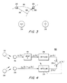
- Figure 3 depicts a typical example of source and sensor placement in two dimensions.
- first and second sensors 215, 225 are positioned adjacent two signal sources 210, 220.
- a signal emanating from the first signal source 210 (as indicated by a first dashed arc 315) will impinge upon the first signal sensor 215 before impinging upon the second signal sensor 225.
- the signal received at the second sensor 225 due to the first signal source 210 will be a delayed and attenuated version of the signal received at the first sensor 215 due to the same source 210.
- a signal emanating from the second source 220 (as indicated by a second dashed arc 325) will impinge upon the second sensor 225 before impinging upon the first sensor 215, and the signal received at the first sensor 215 due to the second signal source 220 will be a delayed and attenuated version of the signal received at the second sensor 225 due to the same source 220.
- the spacial separation (and thus the corresponding time delay and level attenuation) of the sensors 215, 225 with respect to the first and second signal sources 210, 220 are indicated in Figure 3 by second and first line segments 320, 310, respectively.
- the second sensor input x 2 ( k ) is generally a delayed and scaled version of the first sensor input x 1 ( k ).
- x 2 ( k ) 1/ S ⁇ x 1 ( k - D ), where the scale factor S is greater than zero and where the delay D may take positive as well as negative values.
- the first input x 1 ( k ) is a delayed and scaled version of the second input x 2 ( k ).
- the second input x 2 ( k ) is denoted the delayed signal for all values of D without loss of generality.
- D is defined to be ⁇ - D . Note that, for causal filtering, ⁇ > D .
- Figure 4 illustrates the input signals x 1 ( k ), x 2 ( k ) and the intermediate signals y 1 ( k ), y 2 ( k ) in the context of a level and delay measurement system.
- the system 400 of Figure 4 is identical to the system 200 of Figure 2 except that a delay block 410 (corresponding to the fixed delay ⁇ described above) is positioned between the first sensor 215 and the fixed filter 230.
- a delay block 410 corresponding to the fixed delay ⁇ described above
- the present invention provides a computationally simple yet accurate method for estimating the delay D and the scale factor S based on the measured sensor inputs x 1 ( k ) and x 2 ( k ).
- the method is robust against background noise so that it may be used successfully, for example, in the above described hands-free mobile telephony context.
- the estimated quantities say D k and S k (where k indicates that sensor inputs up to and including time instant k are used for the calculation of D and S ), can be used to improve system performance.
- the estimates D k and ⁇ k can be used in combination with well known beamforming techniques to electronically enhance and reduce the sensitivity of the sensors 215, 225 with respect to the first and second sources 210, 220.
- a beam may be formed in the direction of that source to optimize its reception.
- spatial filtering can be employed to diminish the sensitivity of the sensors with respect to that source.
- the system can selectively transmit only the signal detected at a particular sensor when a particular source is active. For example, if one sensor is much more sensitive to the passenger than to the driver (e.g., due to a close physical proximity to the passenger), then it may be desirable to transmit only the signal received at that sensor when only the passenger is speaking.
- ⁇ is a gain factor (constant or time-varying) in the interval 0 ⁇ ⁇ ⁇ 2
- ⁇ 2 denotes the squared Euclidian vector norm.
- the adaptive algorithm described by equations (9) and (10) is the well known Normalized Least Mean Squares (N-LMS) algorithm.
- the coefficients of the adaptive filter 235 converge toward a delayed and scaled version of the coefficients of the fixed filter 230.
- the present invention teaches that by incorporating prior knowledge which distinguishes the source signals from background noise, system performance can be significantly improved. To ensure improved overall performance, the priors should be true in all situations. For example, the present invention teaches that such prior information is available when the energy in the source signals of interest is concentrated around one or more center frequencies, while the background noise has a relatively flat and broadband frequency content, or power spectral density. In such a context, the present invention teaches that the fixed FIR filter 230 can be designed as a band-pass filter having one or several pass bands.
- the fixed filter 230 can be designed to include two pass-bands, the first and second passbands having center frequencies of 100Hz and 250Hz, respectively.
- the fixed filter 230 can be designed to include a single pass-band having a center frequency of 200Hz and spanning a frequency band which includes the fundamental frequency of female speakers as well as the first harmonic frequency of male speakers.
- the former approach requires the use of higher order filters as compared to the latter approach.
- the order L of the filter is doubled as well.
- NG filter noise gain
- the adaptive algorithm used to update the adaptive filter 235 will cause the adaptive filter 235 to converge toward a delayed and scaled replica of the fixed filter 230.
- the coefficients of the adaptive filter 235 will converge as follows: c ⁇ k - S ⁇ c - D where S and D are the scale factor and time delay, respectively, caused by the physical separation of the sensors 215, 225.
- S and D are the scale factor and time delay, respectively, caused by the physical separation of the sensors 215, 225.
- the estimate D k can be computed iteratively in practice. Note that the delay gradient d p ( D )/ dD follows readily from equation (19).
- the present invention teaches that estimates of the scale factor S and the time delay D can be computed in a straightforward fashion.
- each of the above described computations can be carried out using well known digital signal processing components. Due to the consistent prior information provided by the fixed filter 230, the estimates will be valid even in the presence of background noise.
- the system can be further enhanced by the addition of an activity detector which ensures proper system performance even when all signal sources are inactive.
- an activity detector which ensures proper system performance even when all signal sources are inactive.
- the signals x 1 ( k ) and x 2 ( k ) received at the sensors 215, 225 will comprise uncorrelated noise only.
- the adaptive filter coefficients ⁇ ( k ) will converge toward the null vector, meaning that the scale factor estimate ⁇ k will tend toward zero while the time delay estimate D k may take any value.
- the estimates ⁇ k , D k can be explicitly set to appropriate values when an activity detector senses the absence of signals of interest.
- An exemplary activity detector compares an estimate of the filter noise gain to a predetermined threshold (i.e., an expected noise gain value).
- a predetermined threshold i.e., an expected noise gain value.
- An exemplary system can be implemented using the following pseudocode. Those skilled in the art will appreciate that such pseudocode is readily adapted for implementation using standard digital signal processing components.
- Scale Factor and Time Delay Estimation Routine Filtering compute output from the fixed FIR filter and the adaptive FIR filter (k denotes the running time index).
- Y ⁇ 1 y ⁇ 1 ⁇ k : - 1 : k - L ;
- Y ⁇ 2 y ⁇ 2 ⁇ k : - 1 : k - L ;
- Energy calculations and gain control A simple gain control scheme is used in order to set the gain ⁇ to zero if there is low energy in the inputs.
- an acoustic scenario is considered in which the sensors are presumed to be microphones and the sources are presumed to be human speakers or loudspeakers transmitting human speech.
- a scenario can arise in the context of hands-free mobile telephony used in an automobile environment.
- the example is restricted to two sensors and two sources, those skilled in the art will appreciate that the approach can be applied using an arbitrary number of sources and sensors.
- a rather severe background noise is typically present (e.g., from an AC-fan, the car engine, the road, the wind etc.).
- the sensitivities of the microphones in different directions are assumed to be as shown in Table 1. TABLE 1 - MICROPHONE SENSITIVITY TO DIFFUSE BACKGROUND NOISE AND SIGNAL SOURCES IN DIFFERENT POSITIONS.
- Signal Source First Sensor 215 e.g., sun-visor microphone
- Second Sensor 225 e.g., built-in microphone
- Second Source 220 -10dB 0dB e.g., passenger
- Additive background noise was modeled as white Gaussian noise.
- the noise signals detected at the first and second sensors 215, 225 are depicted in third and fourth plots 630, 620, respectively, of Figure 6.
- the combined speech and noise signals measured at the first and second sensors 215, 225 are depicted in fifth and sixth plots 650, 660, respectively of Figure 6.
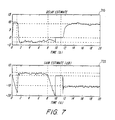
- the results are shown in Figure 7.
- the delay estimate D k is depicted in a first plot 710
- the scale factor estimate S k is depicted in a second plot 720.
- every 50-th sample is displayed.
- Horizontal dashed lines indicate delays of -3, 0, and 9 samples as well as gains of -10dB, 0dB, and 3dB.
- the system properly provides scale factor and time delay estimates, respectively, of 0db and approximately -3 samples when the driver is speaking and -10db and approximately 9 samples when the passenger is speaking.
- the activity detector properly sets the scale factor and time delay estimates, respectively, to 0db and 0 samples during the period when both the driver and the passenger are silent.
- the adaptive scheme comprises an adaptive block that can serve as a signal smoother, a backward predictor ( D ⁇ 0) and/or a forward predictor ( D > 0).
- D ⁇ 0
- D > 0 a forward predictor
- ⁇ can be set based upon system design considerations. For example, ⁇ can be set to cover "most situations” and not “all possible situations” since the system will provide reasonable results even in rare extreme situations.
Description
- The present invention relates to signal processing, and more particularly to the measurement of signal levels and time delays at multiple signal sensors.
- In many signal processing applications, it is desirable to determine the relative sensitivity of multiple signal sensors with respect to a particular signal source. For example, in the context of hands-free mobile telephony, dual microphones can be used in combination with beamforming methods to reduce the effects of background noise and echoes in an automobile. To do so, information regarding the relative sensitivities of the microphones with respect to different acoustic sources is used, for example, to form a spatial beam toward a particular user and/or to form a spatial notch against another user or a loudspeaker. Such an approach requires that dynamic information with respect to microphone sensitivity be quickly and accurately obtained.
- Figure 1 depicts a
prior art system 100 for measuring the relative sensitivities of dual microphones with respect to different signal sources in the context of hands-free mobile telephony. As shown, theprior art system 100 includes afirst microphone 115, asecond microphone 125, anadaptive filter 135 and asumming device 140. An output y 1(k) of thefirst microphone 115 is coupled to a positive input of thesumming device 140, and an output y 2(k) of thesecond microphone 125 is coupled to an input of theadaptive filter 135. An output ŷ 1(k) of theadaptive filter 135 is coupled to a negative input of thesumming device 140, and an output e(k) of thesumming device 140 is used as a feedback signal to theadaptive filter 135. - As shown, the
first microphone 115 is positioned nearer afirst source 110, and thesecond microphone 125 is positioned nearer asecond source 120. For example, thefirst microphone 115 can be a hands-free microphone attached to a sun visor situated nearer a driver of an automobile, and thesecond microphone 125 can be a built-in microphone within a mobile unit attached nearer a passenger in the automobile. Although it is not shown in Figure 1, those skilled in the art will appreciate that analog pre-processing and analog-to-digital conversion circuitry can be included at the output of each of the first andsecond microphones adaptive filter 135 and thesumming device 140. The output e(k) of thesumming device 140 represents the difference between the output y 1(k) of thefirst microphone 115 and the output ŷ 1(k) of theadaptive filter 135 and is referred to herein as an error signal. - In operation, filter coefficients of the
adaptive filter 135 are adjusted using a least-squares algorithm such that the error signal e(k) is minimized. In other words, theadaptive filter 135 is adjusted such that the output ŷ 1(k) of theadaptive filter 135 is as close as possible to (i.e., is an estimator of) the output y 1(k) of thefirst microphone 115. Thus, theadaptive filter 135 attempts to model the signal effects created by the physical separation of themicrophones passenger 120 is speaking, his or her voice will reach thefirst microphone 115 slightly later than it will reach thesecond microphone 125, and the corresponding speech signal level received at thefirst microphone 115 will be somewhat attenuated as compared to the level received at thesecond microphone 125. Thus, theadaptive filter 135 is adjusted to provide similar delay and attenuation effects. - As a result, the relative time delay and signal attenuation at the microphones with respect to each user can be calculated based on the coefficients of the
adaptive filter 135 as described, for example, in Y.T. Chan, J.M. Riley and J.B. Plant, "A parameter estimation approach to time delay estimation and signal detection", IEEE Transactions on Acoustics, Speech and Signal Processing, vol. ASSP-28, Feb. 1980. - One disadvantage of the system of Figure 1, however, is that its performance deteriorates significantly in the presence of background noise. As a result, the system of Figure 1 is not useful in most practical applications, where significant background noise (e.g., road and traffic noise) is commonplace. Thus, there is a need for improved methods and apparatus for measuring relative signal levels and time delays at multiple sensors.
- US-A-4,672,674 discloses a system for noise cancellation, in which inputs from two microphones are both filtered, and the resulting filtered signals are summed. An adaptive filter in one of the input paths is adjusted to enable improved noise cancellation.
- The present invention fulfills the above-described and other needs by providing a system according to
claim 1 in which a fixed filter and an adaptive filter are used in combination to provide accurate and robust estimates of signal levels and time delays for multiple sensors. In exemplary embodiments, the fixed filter includes at least one relatively narrow passband which is used to distinguish signal sources of interest from broad-band background noise. In the embodiments, the fixed filter is coupled to a reference sensor and the adaptive filter is coupled to a secondary sensor. An error signal derived from the outputs of the fixed filter and the adaptive filter is used to adjust filter coefficients of the adaptive filter according to a suitable least-squares algorithm. The coefficients of the fixed filter and the adaptive filter are used to compute estimates of the time delay and relative level between the two sensors. The estimates can then be used to make decisions regarding sensor selection and beamforming. - In exemplary embodiments, the functionality of the system is supplemented with an activity detector which indicates when no signal of interest is present. In the activity detector, accumulated energy in the adaptive filter is compared with an expected least value derived from the coefficients of the fixed filter. When the accumulated energy is smaller than the expected value, indicating that there is no signal of interest present (i.e., only background noise is present), the time delay and relative level estimates are set to appropriate values to ensure proper operation of the system even during periods where no signals of interest are present.
- In additional embodiments, more than two signal sensors are employed. In such embodiments, one sensor is treated as a reference sensor and coupled to a fixed filter, while each of the additional sensors is coupled to an adaptive filter. For each additional sensor, an error signal derived from the outputs of the fixed filter and the corresponding adaptive filter is used to update the coefficients of the corresponding adaptive filter. Thus, robust estimates of the time delay and relative signal level between the reference sensor and each additional sensor can be computed, and sophisticated decisions can be made with respect sensor selection and beamforming.
- Generally, the present invention provides a computationally simple yet accurate and robust method according to claim 23 for estimating the time delays and relative signal levels at multiple sensors. The teachings of the invention are applicable in a wide variety of signal processing contexts. For example, in addition to the hands-free mobile telephony application described above, the invention may be used for other acoustic applications such as teleconferencing. Additionally, the present invention is applicable in radio communication applications where the signals of interest are radio-frequency transmissions (e.g., from mobile units and/or base stations in a cellular radio system) and the sensors are radio-frequency-sensitive antenna elements. These and other features and benefits of the present invention are explained hereinafter with reference to the illustrative examples shown in the accompanying drawings.
-
- Figure 1 depicts the prior art signal level and delay measurement system described above.
- Figure 2 depicts a signal level and delay measurement system constructed in accordance with the present invention.
- Figure 3 depicts relative signal levels and time delays of two signals detected at dual signal sensors.
- Figure 4 depicts an alternate signal level and delay measurement system constructed in accordance with the present invention.
- Figure 5 depicts magnitude and phase responses of an exemplary signal filter which can be employed in the exemplary systems of Figures 2 and 4.
- Figure 6 depicts exemplary speech and noise signals which are used to demonstrate operation of exemplary embodiments of the present invention.
- Figure 7 depicts signal level and delay estimates generated by an exemplary embodiment of the present invention based on the signals of Figure 6.
- Figure 2 depicts a level and
delay measurement system 200 constructed in accordance with the teachings of the present invention. As shown, thesystem 200 includes afirst sensor 215, asecond sensor 225, afixed FIR filter 230, anadaptive FIR filter 235 and asumming device 240. An output y 1(k) of thefirst sensor 215 is coupled to an input of thefixed filter 230, and an output y F(k) of thefixed filter 230 is coupled to a positive input of thesumming device 240. An output y 2(k) of thesecond sensor 225 is coupled to an input of theadaptive filter 235 and an output ŷ(k) of theadaptive filter 235 is coupled to a negative input of thesumming device 240. An error signal e(k) which is output by thesumming device 240 is fed back to theadaptive filter 235. - As shown, the
first sensor 215 is positioned nearer afirst signal source 210, and thesecond sensor 225 is positioned nearer asecond signal source 220. For example, thefirst sensor 215 can be a hands-free microphone attached to a sun visor situated nearer a driver of an automobile, and thesecond sensor 225 can be a built-in microphone within a mobile unit attached nearer a passenger in the automobile. Alternatively, the first andsecond sensors second sensors filter 230, theadaptive filter 235 and the summingdevice 240. - The fixed
filter 230 is designed to include at least one relatively narrow pass-band of interest. For example, in the mobile telephony context, a pass-band can correspond to the 300-600 Hz frequency band in which most of the energy of human speech is concentrated. In a radio communication application, a pass-band can correspond to a bandwidth allocated for radio-frequency transmissions. In any case, the coefficients of the fixedfilter 230 can be adjusted as necessary to compensate for changes in application requirements or environmental conditions. For example, in a hands-free mobile telephone application, the fixedfilter 230 can be set to optimize received signal-to-noise ratio for a particular automobile installation. Furthermore, the coefficients of thefilter 230 can be adjusted dynamically, for example in dependence upon measured signal-to-noise ratio. - According to the invention, the fixed
filter 230 is designed to provide unity gain and zero phase in each passband. Additionally, the noise gain of the fixedfilter 230 is minimized in order to ensure maximal stop-band attenuation. As described in more detail below, the prior information provided by the fixed filter 230 (i.e., the narrowband nature of the signals output by the fixed filter 230) is used to make the system robust against background noise. - In operation, filter coefficients of the
adaptive filter 235 are adjusted using a suitable least-squares algorithm such that the error signal e(k) is minimized and such that the output ŷ(k) of theadaptive filter 235 is as close as possible to the output y F(k) of the fixedfilter 230. As described below, the relative time delay and signal attenuation at the first andsecond sensors source adaptive filter 235 and the prior information associated with the fixedfilter 230. Although not explicitly shown in Figure 2, those skilled in the art will appreciate that an appropriate digital signal processor can be integrated with thesystem 200 to perform the least-squares update of theadaptive filter 235 and to compute the time delay and signal level estimates. - In order to clarify the operation of the
system 200 of Figure 2, a rigorous mathematical analysis is developed below with respect to Figures 3 and 4. Although the analysis is explicitly developed for two sensors and two signal sources, those skilled in the art will appreciate that the described approach is readily applicable to applications including an arbitrary number of signal sources and sensors. Additionally, although reference is sometimes made to the acoustic hands-free mobile telephony application described above, those skilled in the art will appreciate that the described approach is also applicable to many other signal processing contexts including the radio communications applications previously mentioned. - Figure 3 depicts a typical example of source and sensor placement in two dimensions. In the figure, first and
second sensors signal sources first signal sensor 215 before impinging upon thesecond signal sensor 225. Thus, the signal received at thesecond sensor 225 due to thefirst signal source 210 will be a delayed and attenuated version of the signal received at thefirst sensor 215 due to thesame source 210. Additionally, a signal emanating from the second source 220 (as indicated by a second dashed arc 325) will impinge upon thesecond sensor 225 before impinging upon thefirst sensor 215, and the signal received at thefirst sensor 215 due to thesecond signal source 220 will be a delayed and attenuated version of the signal received at thesecond sensor 225 due to thesame source 220. The spacial separation (and thus the corresponding time delay and level attenuation) of thesensors second signal sources first line segments - If the first and second sensor inputs (after analog pre-processing and analog-to-digital conversion) at time instant k are denoted by x 1(k) and x 2(k), respectively, then the second sensor input x 2(k) is generally a delayed and scaled version of the first sensor input x 1(k). In other words, x 2(k) = 1/S·x 1(k-
D ), where the scale factor S is greater than zero and where the delayD may take positive as well as negative values. Strictly speaking, forD < 0 (e.g., for signals emanating from the second signal source 220), the first input x 1(k) is a delayed and scaled version of the second input x 2(k). However, in order to simplify notation, the second input x 2(k) is denoted the delayed signal for all values ofD without loss of generality. - In order to provide a causal filtering problem, a fixed delay Δ can be introduced into the signal path following the first sensor. While this is a natural approach in most applications, it is not a prerequisite for the invention to work as intended. This fact is explained in greater detail below. With the extra delay Δ introduced, one can define first and second intermediate signals y 1(k), y 2(k) as follows:


where q denotes the well known delay operator (i.e., qy(k)=y(k+1), q -1 y(k)=y(k-1), etc.), and where D is defined to be Δ-D . Note that, for causal filtering, Δ >D . - To aid discussion, Figure 4 illustrates the input signals x 1(k), x 2(k) and the intermediate signals y 1(k), y 2(k) in the context of a level and delay measurement system. The
system 400 of Figure 4 is identical to thesystem 200 of Figure 2 except that a delay block 410 (corresponding to the fixed delay Δ described above) is positioned between thefirst sensor 215 and the fixedfilter 230. In the discussion that follows, it is assumed that the coefficients of the fixedfilter 230 are stored in a first coefficient vector c0 and that the time-varying coefficients of theadaptive filter 235 are stored in a second coefficient vector ĉ(k). - Generally, the present invention provides a computationally simple yet accurate method for estimating the delay D and the scale factor S based on the measured sensor inputs x 1(k) and x 2(k). Advantageously, the method is robust against background noise so that it may be used successfully, for example, in the above described hands-free mobile telephony context. The estimated quantities, say Dk and S k (where k indicates that sensor inputs up to and including time instant k are used for the calculation of D and S), can be used to improve system performance.
- For example, in the context of mobile telephony, the estimates Dk and Ŝk can be used in combination with well known beamforming techniques to electronically enhance and reduce the sensitivity of the
sensors second sources - Furthermore, the system can selectively transmit only the signal detected at a particular sensor when a particular source is active. For example, if one sensor is much more sensitive to the passenger than to the driver (e.g., due to a close physical proximity to the passenger), then it may be desirable to transmit only the signal received at that sensor when only the passenger is speaking.
- Returning to Figure 4, the signal yF (k) output by the fixed filter 230 (i.e., the filtered version of the first intermediate signal y 1(k)) is given by:


where L is the order of the fixedfilter 230, and where {c ℓ}, ℓ = 0,..., L are the fixed filter coefficients. Additionally, the signal ŷ(k) output by the adaptive filter 235 (i.e., the filtered version of the second intermediate signal y 2(k)) is given by:


where the vector ĉ(k) contains the time varying filter coefficients of theadaptive filter 235. The vector ĉ(k) is updated based on the error signal e(k) as follows:

where µ is a gain factor (constant or time-varying) in theinterval 0 ≤ µ < 2, and where ∥·∥2 denotes the squared Euclidian vector norm. The adaptive algorithm described by equations (9) and (10) is the well known Normalized Least Mean Squares (N-LMS) algorithm. Alternative adaptive schemes, such as the Recursive Least Squares (RLS) algorithm or the Least Mean Squares (LMS) algorithm can also be used. For a more detailed description of adaption algorithms generally, see for example B. Widrow and S.D. Stearns, Adaptive Signal Processing, Prentice Hall, Englewood Cliffs, NJ, 1985, and L. Ljung and T. Söderström, Theory and Practice of Recursive Identification, M.I.T. Press, Cambridge, MA, 1983. Advantageously, each of the above defined quantities can be computed using standard digital signal processing components. - For a broadband source impinging on the
sensors adaptive filter 235 converge toward a delayed and scaled version of the coefficients of the fixedfilter 230. In particular, if every coefficient of the fixed vector c 0 is 1 (i.e., if effectively no fixed filter is used), the time-varying vector ĉ(k) converges toward an approximation of the scaled delay (i.e., SqD -Δ = Sq-D ). Such a result has been used to estimate time-delays in prior art systems. See, for example, Y.T. Chan, J.M.F. Riley and J.B. Plant, "Modeling of time delay and its application to estimation of nonstationary delays", IEEE Transactions on Acoustics, Speech, and Signal Processing, Vol. ASSP-29, No. 3, pp. 577-581, June 1981. One disadvantage associated with such systems is that overall system performance deteriorates significantly when background noise is present, making the systems impractical in most real-world applications. - Advantageously, the present invention teaches that by incorporating prior knowledge which distinguishes the source signals from background noise, system performance can be significantly improved. To ensure improved overall performance, the priors should be true in all situations. For example, the present invention teaches that such prior information is available when the energy in the source signals of interest is concentrated around one or more center frequencies, while the background noise has a relatively flat and broadband frequency content, or power spectral density. In such a context, the present invention teaches that the fixed
FIR filter 230 can be designed as a band-pass filter having one or several pass bands. - For example, for speech signals in a mobile hands-free scenario, it is reasonable to assume that the energy of the speech signals is concentrated in the interval 100-250Hz. More specifically, the fundamental frequency of a male speaker is typically around 100Hz, and the fundamental frequency of a female speaker is typically around 250Hz. In view of this information, the present invention teaches several possible designs alternatives for the fixed
filter 230. For example, the fixedfilter 230 can be designed to include two pass-bands, the first and second passbands having center frequencies of 100Hz and 250Hz, respectively. Alternatively, the fixedfilter 230 can be designed to include a single pass-band having a center frequency of 200Hz and spanning a frequency band which includes the fundamental frequency of female speakers as well as the first harmonic frequency of male speakers. - In practice, the former approach requires the use of higher order filters as compared to the latter approach. Generally, if the number of design frequencies are doubled, then the order L of the filter is doubled as well. In the discussion that follows, a fixed
filter 230 having m distinct pass-bands is considered. At the center frequencies {ωℓ}, ℓ = 1,...,m, the filter is designed to provide unity gain and zero phase. Additionally, the fixedfilter 230 is designed to provide maximal attenuation in the stop-bands by minimizing the filter noise gain (NG) which is defined as:
where C 0(z -1) = c 0 + c 1 z -1+···+cLz-L , and where the integration proceeds around the unit circle. By Parseval relation, the noise gain for FIR filters is given by:
- To design the fixed
filter 230, consider an input signal y in(k) comprising a sum of sinusoids as follows:
where {ωℓ},ℓ = 1,...,m are the desired center frequencies of the fixed FIR filter, ωℓ ∈ (0,π), ωℓ ≠ ωj,ℓ ≠ j, {αℓ} are unknown constants αℓ > 0,ℓ = 1,...,m, and {φℓ} are uniformly distributed random variables φℓ ∈ (-π,π],ℓ = 1,...,m. Next consider a fixedFIR filter 230 having a coefficient vector c d and providing an output y out(k) which is an exact d-step prediction (after any initial transients have decayed) of the input y in(k) for any d, -∞ < d < ∞, as follows:


- For d = 0 (i.e., for a coefficient vector c0), the fixed
FIR filter 230 provides unity gain and zero phase at the center frequencies {ωℓ},ℓ = 1,...,m as desired. Additionally, if the sensitivity to broadband noise is minimized (i.e., if the quantity in equation (12) is minimized), then (for a filter length L, such that L > 2m - 1) the following result holds true:
where L is the 2m x (L + 1) matrix:
and where p(d) is the 2m prediction vector:
- First and
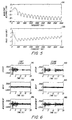
second plots filter 230 designed using the approach described above with d = 0, L = 32, m = 1, ω1 = 200 Hz and a sampling rate of 8000 Hz. As shown by dashed lines in Figure 5, the fixedfilter 230 provides unity gain and zero phase at the center frequency 200Hz as desired. - As described above, the adaptive algorithm used to update the
adaptive filter 235 will cause theadaptive filter 235 to converge toward a delayed and scaled replica of the fixedfilter 230. Specifically, for a fixedFIR filter 230 with d = 0 (i.e., coefficients c0), the coefficients of theadaptive filter 235 will converge as follows:
where S and D are the scale factor and time delay, respectively, caused by the physical separation of thesensors adaptive filter 235, then the estimate Ŝk can be computed from equation (20) as follows:
- Furthermore, S can be estimated without prior knowledge of D. To see this, first note that equation (21) is a vector equality in which both c -D and ĉ(k) are vectors of
size L + 1. Then, from equation (17), it follows that Lc -D = p(-D). Thus, multiplication of both sides of equation (21) from the left with the 2m x (L + 1) matrix L defined in equation (18), gives the following result:
where both sides of equation (22) are 2m-vectors. Then, given that p(D)T p(D) = m (see equation (19)), equation (22) can be re-written as follows:
- From equation (23), and from the fact that S > 0, the estimate Ŝk of the scale factor S at time instant k can be computed as:

- Given an estimate Ŝ k of the scale factor S, an estimate Dk of the time delay D can be computed using a least squares fit as follows:

- Equivalently, an estimate Dk of the time delay D can be computed as:

- Advantageously, the estimate Dk can be computed iteratively in practice. Note that the delay gradient d p(D)/dD follows readily from equation (19).
- Thus, the present invention teaches that estimates of the scale factor S and the time delay D can be computed in a straightforward fashion. Advantageously, each of the above described computations can be carried out using well known digital signal processing components. Due to the consistent prior information provided by the fixed
filter 230, the estimates will be valid even in the presence of background noise. - The system can be further enhanced by the addition of an activity detector which ensures proper system performance even when all signal sources are inactive. For example, when neither
source sensors - An exemplary activity detector compares an estimate of the filter noise gain to a predetermined threshold (i.e., an expected noise gain value). An appropriate threshold can be derived from equation (12) as follows:

- In operation, the activity detector computes an estimate NG of the filter noise gain as a sum of squares of the adaptive filter taps (i.e., NG = ĉ(k) T ĉ(k)). If the estimate NG is much smaller than the predetermined threshold, then the delay estimate Dk is set to zero, and the scale factor estimate Ŝk is set to unity to ensure proper system operation. Note that since the value of the noise gain NG is independent of the delay D, it is sufficient that a single threshold be stored.
- An exemplary system can be implemented using the following pseudocode. Those skilled in the art will appreciate that such pseudocode is readily adapted for implementation using standard digital signal processing components.
- Scale Factor and Time Delay Estimation Routine Filtering: compute output from the fixed FIR filter and the adaptive FIR filter (k denotes the running time index).


g(k) = mu;
else
g(k) = 0;
end
N-LMS update: Update of the adaptive filter coefficients using the N-LMS algorithm.
channel 1.


Shat = 1;
Dhat = 0;
end
The estimates of S and D are further smoothed by a first order running mean:


- To further illustrate operation of the exemplary embodiments, a numerical example using the pseudocode above is provided. In the example, an acoustic scenario is considered in which the sensors are presumed to be microphones and the sources are presumed to be human speakers or loudspeakers transmitting human speech. As noted above, such a scenario can arise in the context of hands-free mobile telephony used in an automobile environment. Though the example is restricted to two sensors and two sources, those skilled in the art will appreciate that the approach can be applied using an arbitrary number of sources and sensors.
- With a distance of 0.5 meters between the
first source 210 and thefirst sensor 215, and with thefirst sensor 215 treated as a reference sensor, the actual time delay at thesecond sensor 225 with respect to thefirst source 210 isD = 2.25 samples for a sampling rate of 8kHz. Using the same assumptions, the actual time delay at thesecond sensor 225 with respect to thesecond source 220 isD = -8.75 samples. These assumptions are reasonable, for example, for a car compartment with a mobile phone (containing the second sensor 225) placed in its cradle near the passenger (the second source 220) and an extra stick-on microphone (the first sensor 215) placed on the sun visor in front of the driver (the first source 210). - In such a car compartment, a rather severe background noise is typically present (e.g., from an AC-fan, the car engine, the road, the wind etc.). For purposes of the numeric example, the sensitivities of the microphones in different directions are assumed to be as shown in Table 1.
TABLE 1 - MICROPHONE SENSITIVITY TO DIFFUSE BACKGROUND NOISE AND SIGNAL SOURCES IN DIFFERENT POSITIONS. Signal Source First Sensor 215 (e.g., sun-visor microphone) Second Sensor 225 e.g., built-in microphone)Diffuse 0dB 0dB Background Noise First Source 210 + 3dB 0dB (e.g., driver) Second Source 220 -10dB 0dB (e.g., passenger) - Additionally, synthetic two-channel measurements were created with a male speaker at the location of the
first source 210 and a female speaker at the location of thesecond source 220. The files were concatenated such that there was no speaker activity the first second, then the male speaker was active for 7s, then there was no activity for 3s, and then the female speaker was active for 10s. The signal to noise ratio with respect to thesecond sensor 225 was 8dB for the male speaker and 7dB for the female speaker (measured over the total period during which they were active). The speech signal detected at the first andsecond sensors second plots - Additive background noise was modeled as white Gaussian noise. The noise signals detected at the first and
second sensors fourth plots second sensors sixth plots - In the simulation, the parameters used were: L = 32, Δ = 10, ω = 2π200/8000, m = 1, µ = 0.01 and rho = 0.99. The results are shown in Figure 7. Specifically, the delay estimate Dk is depicted in a
first plot 710, and the scale factor estimate Sk is depicted in asecond plot 720. In bothplots - Although the embodiments have been described in the context of causal filtering (i.e., Δ > 0), the teachings of the present invention are equally applicable in the context of non-causal filtering. Specifically, for Δ = 0 the adaptive scheme comprises an adaptive block that can serve as a signal smoother, a backward predictor (D < 0) and/or a forward predictor (D > 0). Thus, it is not necessary that a fixed delay be added in the signal flow (e.g., via delay block 410), and an adaptive scheme with minimum inherent delay can be realized. Such a property can be of substantial practical relevance in many real-time applications. However, because the quality of the estimates will be somewhat less accurate with a non-causal approach (and because narrower pass-bands are required for the fixed FIR filter 230), the precise value of Δ can be set based upon system design considerations. For example, Δ can be set to cover "most situations" and not "all possible situations" since the system will provide reasonable results even in rare extreme situations.
- Those skilled in the art will appreciate that the present invention is not limited to the specific exemplary embodiments which have been described herein for purposes of illustration. The scope of the invention, therefore, is defined by the claims which are appended hereto, rather than the foregoing description, and all equivalents which are consistent with the meaning of the claims are intended to be embraced therein.
Claims (28)
- A signal processing device, comprising:a first signal sensor (215);a second signal sensor (225);an adaptive filter (235) having an input coupled to an output of said second sensor and having an adjustable filtering characteristic;a summing device (240), wherein the adjustable filtering characteristic of said adaptive filter (235) is adjusted in dependence upon an output of said summing device (240); anda processor;a bandpass filter (230) having an input coupled to an output of said first sensor, said bandpass filter having a passband corresponding to a frequency band containing a signal of interest;said summing device (240) having a first input coupled to an output of said bandpass filter (230) and a second input coupled to an output of said adaptive filter (235); means for adjusting the filtering characteristic of the adaptive filter such that an output of the adaptive filter is as close as possible to an output of the bandpass filter; andcharacterized in that the processor is adapted to compute estimates of a relative time delay and a relative scale factor between said first and second sensors with respect to a signal source, in dependence upon a filtering characteristic of said bandpass filter and the adjustable filtering characteristic of said adaptive filter.
- A signal processing device according to claim 1, wherein said bandpass filter, said adaptive filter, said summing device and said processor are implemented using a digital signal processor (DSP) integrated circuit (IC).
- A signal processing device according to claim 1, wherein said bandpass filter, said adaptive filter, said summing device and said processor are implemented using an application specific integrated circuit (ASIC).
- A signal processing device according to claim 1, wherein said signal processing device is a telephone and wherein said first and second sensors are microphones.
- A signal processing device according to claim 1, wherein said signal processing device is a radio transceiver and wherein said first and second sensors are antenna elements.
- A signal processing device according to claim 1, wherein said bandpass filter is a finite impulse response (FIR) filter having a fixed filtering characteristic.
- A signal processing device according to claim 1, wherein the filtering characteristic of said bandpass filter includes at least one passband providing unity gain and zero phase delay at a center frequency of the passband.
- A signal processing device according to claim 1, wherein the filtering characteristic of said bandpass filter includes coefficients which are set to minimize a noise gain of said bandpass filter.
- A signal processing device according to claim 1, wherein the filtering characteristic of said bandpass first filter includes coefficients which are adjusted to optimize a signal-to-noise ratio of said bandpass filter.
- A signal processing device according to claim 1, wherein the adjustable filtering characteristic of said adaptive filter is adjusted using a Normalized Least Mean Squares (NLMS) algorithm.
- A signal processing device according to claim 1, wherein the adjustable filtering characteristic of said adaptive filter is adjusted using a Least Mean Squares (LMS) algorithm.
- A signal processing device according to claim 1, wherein the adjustable filtering characteristic of said adaptive filter is adjusted using a Recursive Least Squares (RLS) algorithm.
- A signal processing device according to claim 1, further comprising a beamformer for shaping a beam pattern provided by said first and second sensors in dependence upon the estimates of the relative time delay and the relative scale factor between said first and second sensors.
- A signal processing device according to claim 13, wherein the beam pattern includes a spacial beam aimed toward a particular signal source.
- A signal processing device according to claim 13, wherein the beam pattern includes a spacial notch aimed against a particular signal source.
- A signal processing device according to claim 1, wherein said processor selects a signal detected by a particular one of said first and second sensors for transmission in dependence upon the estimates of the relative time delay and the relative scale factor between said first and second sensors.
- A signal processing device according to claim 1, further comprising at least one additional sensor and at least one additional filter having an adjustable filtering characteristic,
wherein the adjustable filtering characteristic of said additional filter is adjusted in dependence upon a difference between the output of said bandpass filter and an output of said additional filter, and
wherein said processor computes an estimate of at least one parameter relating to said first sensor and said additional sensor in dependence upon the filtering characteristic of said bandpass filter and the adjustable filtering characteristic of said additional filter. - A signal processing device according to claim 17, wherein said processor computes estimates of a relative time delay and a relative scale factor between said first sensor and said additional sensor with respect to a signal source.
- A signal processing device according to claim 1, further comprising an activity detector for detecting when a signal source of interest is active,
wherein said processor sets the estimates of the relative time delay and the relative scale factor to predetermined values when said activity detector indicates that no signal source of interest is active. - A signal processing device acccording to claim 19, wherein said processor sets the estimate of the relative time delay to zero and the estimate of the scale factor to one when said activity detector indicates that no signal source of interest is active.
- A signal processing device according to claim 1, further comprising a fixed-delay block positioned in a signal flow path corresponding to said first sensor.
- A signal processing device according to claim 1,
wherein filtering characteristics of said bandpass filter and said adaptive filter each include a number L of filtering coefficients,
wherein the filtering characteristic of said bandpass filter includes a number m of passbands, each passband ℓ, ℓ ∈(1,m), having a center frequency ωℓ, and
wherein an estimate Dk of a relative time delay D between said first and second sensors and an estimate Ŝk of a relative scale factor S between said first and second sensors, at a time instant k, are computed based upon the adjustable filtering characteristic ĉ(k) of said adaptive filter, a matrix L, and a prediction vector p(D), as:

where the matrix L and the prediction vector p(D) are computed as:

- A method for processing signals, comprising the steps of:detecting a first signal using a first signal sensor;detecting a second signal using a second signal sensor;filtering the second signal using an adaptive filter having an adjustable filtering characteristic to provide a filtered second signal;filtering the first signal using a bandpass filter, having a passband corresponding to a frequency band containing a signal of interest, to provide a filtered first signal;computing a difference between the filtered first signal and the filtered second signal;adjusting the filtering characteristic of the adaptive filter such that said difference is minimized; and characterized bycomputing estimates of a relative time delay and a relative scale factor between said first and second sensors with respect to a signal source, in dependence upon a filtering characteristic of said bandpass filter and the adjustable filtering characteristic of said adaptive filter.
- A method according to claim 23, wherein the filtering characteristic of the bandpass filter includes at least one passband providing unity gain and zero phase delay at a center frequency of the passband.
- A method according to claim 23, wherein the filtering characteristic of said adaptive filter is adjusted using a Normalized Least Mean Squares (NLMS) algorithm.
- A method according to claim 23, further comprising a step of shaping a beam pattern provided by said first and second sensors in dependence upon the relative time delay and the relative scale factor obtained as a result of said step of estimating.
- A method according to claim 23, further comprising a step of selecting and transmitting a signal detected by a particular one of said first and second sensors in dependence upon the relative time delay and the relative scale factor obtained as a result of said step of estimating.
- A method according to claim 23, further comprising the steps of detecting whether a signal source of interest is active and setting relative time delay and scale factor estimates to predetermined values when said step of detecting indicates that no source of interest is active.
Applications Claiming Priority (3)
| Application Number | Priority Date | Filing Date | Title |
|---|---|---|---|
| US08/890,768 US6430295B1 (en) | 1997-07-11 | 1997-07-11 | Methods and apparatus for measuring signal level and delay at multiple sensors |
| US890768 | 1997-07-11 | ||
| PCT/SE1998/001319 WO1999003091A1 (en) | 1997-07-11 | 1998-07-03 | Methods and apparatus for measuring signal level and delay at multiple sensors |
Publications (2)
| Publication Number | Publication Date |
|---|---|
| EP0995188A1 EP0995188A1 (en) | 2000-04-26 |
| EP0995188B1 true EP0995188B1 (en) | 2007-04-25 |
Family
ID=25397124
Family Applications (1)
| Application Number | Title | Priority Date | Filing Date |
|---|---|---|---|
| EP98934034A Expired - Lifetime EP0995188B1 (en) | 1997-07-11 | 1998-07-03 | Methods and apparatus for measuring signal level and delay at multiple sensors |
Country Status (15)
| Country | Link |
|---|---|
| US (1) | US6430295B1 (en) |
| EP (1) | EP0995188B1 (en) |
| JP (1) | JP4082649B2 (en) |
| KR (1) | KR100480404B1 (en) |
| CN (1) | CN1122963C (en) |
| AU (1) | AU747618B2 (en) |
| BR (1) | BR9810695A (en) |
| DE (1) | DE69837663D1 (en) |
| EE (1) | EE200000008A (en) |
| HK (1) | HK1031421A1 (en) |
| MY (1) | MY120049A (en) |
| PL (1) | PL337971A1 (en) |
| SG (1) | SG70644A1 (en) |
| TW (1) | TW386330B (en) |
| WO (1) | WO1999003091A1 (en) |
Families Citing this family (65)
| Publication number | Priority date | Publication date | Assignee | Title |
|---|---|---|---|---|
| US7146013B1 (en) * | 1999-04-28 | 2006-12-05 | Alpine Electronics, Inc. | Microphone system |
| US20010028718A1 (en) | 2000-02-17 | 2001-10-11 | Audia Technology, Inc. | Null adaptation in multi-microphone directional system |
| WO2001069968A2 (en) | 2000-03-14 | 2001-09-20 | Audia Technology, Inc. | Adaptive microphone matching in multi-microphone directional system |
| AU2001247677A1 (en) * | 2000-03-20 | 2001-10-03 | Apherma Corporation | Directional processing for multi-microphone system |
| US6861946B2 (en) * | 2000-05-17 | 2005-03-01 | Caveo Technology Llc. | Motion-based input system for handheld devices |
| US8280072B2 (en) | 2003-03-27 | 2012-10-02 | Aliphcom, Inc. | Microphone array with rear venting |
| US8467543B2 (en) * | 2002-03-27 | 2013-06-18 | Aliphcom | Microphone and voice activity detection (VAD) configurations for use with communication systems |
| US20030179888A1 (en) * | 2002-03-05 | 2003-09-25 | Burnett Gregory C. | Voice activity detection (VAD) devices and methods for use with noise suppression systems |
| US8019091B2 (en) * | 2000-07-19 | 2011-09-13 | Aliphcom, Inc. | Voice activity detector (VAD) -based multiple-microphone acoustic noise suppression |
| US7246058B2 (en) * | 2001-05-30 | 2007-07-17 | Aliph, Inc. | Detecting voiced and unvoiced speech using both acoustic and nonacoustic sensors |
| US20070233479A1 (en) * | 2002-05-30 | 2007-10-04 | Burnett Gregory C | Detecting voiced and unvoiced speech using both acoustic and nonacoustic sensors |
| US20020099541A1 (en) * | 2000-11-21 | 2002-07-25 | Burnett Gregory C. | Method and apparatus for voiced speech excitation function determination and non-acoustic assisted feature extraction |
| KR100394840B1 (en) * | 2000-11-30 | 2003-08-19 | 한국과학기술원 | Method for active noise cancellation using independent component analysis |
| US7206418B2 (en) * | 2001-02-12 | 2007-04-17 | Fortemedia, Inc. | Noise suppression for a wireless communication device |
| US20030128848A1 (en) * | 2001-07-12 | 2003-07-10 | Burnett Gregory C. | Method and apparatus for removing noise from electronic signals |
| WO2004056298A1 (en) * | 2001-11-21 | 2004-07-08 | Aliphcom | Method and apparatus for removing noise from electronic signals |
| JP2003241767A (en) * | 2002-02-14 | 2003-08-29 | Alpine Electronics Inc | Noise canceler |
| US6978010B1 (en) | 2002-03-21 | 2005-12-20 | Bellsouth Intellectual Property Corp. | Ambient noise cancellation for voice communication device |
| KR101016251B1 (en) * | 2002-04-10 | 2011-02-25 | 코닌클리케 필립스 일렉트로닉스 엔.브이. | Coding of stereo signals |
| BRPI0308691B1 (en) * | 2002-04-10 | 2018-06-19 | Koninklijke Philips N.V. | "Methods for encoding a multi channel signal and for decoding multiple channel signal information, and arrangements for encoding and decoding a multiple channel signal" |
| TW200425763A (en) | 2003-01-30 | 2004-11-16 | Aliphcom Inc | Acoustic vibration sensor |
| US9066186B2 (en) | 2003-01-30 | 2015-06-23 | Aliphcom | Light-based detection for acoustic applications |
| US9099094B2 (en) | 2003-03-27 | 2015-08-04 | Aliphcom | Microphone array with rear venting |
| US7330556B2 (en) | 2003-04-03 | 2008-02-12 | Gn Resound A/S | Binaural signal enhancement system |
| US8509703B2 (en) * | 2004-12-22 | 2013-08-13 | Broadcom Corporation | Wireless telephone with multiple microphones and multiple description transmission |
| US8345890B2 (en) | 2006-01-05 | 2013-01-01 | Audience, Inc. | System and method for utilizing inter-microphone level differences for speech enhancement |
| US8204252B1 (en) | 2006-10-10 | 2012-06-19 | Audience, Inc. | System and method for providing close microphone adaptive array processing |
| US9185487B2 (en) | 2006-01-30 | 2015-11-10 | Audience, Inc. | System and method for providing noise suppression utilizing null processing noise subtraction |
| US8194880B2 (en) * | 2006-01-30 | 2012-06-05 | Audience, Inc. | System and method for utilizing omni-directional microphones for speech enhancement |
| US8744844B2 (en) | 2007-07-06 | 2014-06-03 | Audience, Inc. | System and method for adaptive intelligent noise suppression |
| US8150065B2 (en) * | 2006-05-25 | 2012-04-03 | Audience, Inc. | System and method for processing an audio signal |
| US8204253B1 (en) | 2008-06-30 | 2012-06-19 | Audience, Inc. | Self calibration of audio device |
| US8949120B1 (en) | 2006-05-25 | 2015-02-03 | Audience, Inc. | Adaptive noise cancelation |
| US8849231B1 (en) | 2007-08-08 | 2014-09-30 | Audience, Inc. | System and method for adaptive power control |
| US8934641B2 (en) | 2006-05-25 | 2015-01-13 | Audience, Inc. | Systems and methods for reconstructing decomposed audio signals |
| US8259926B1 (en) | 2007-02-23 | 2012-09-04 | Audience, Inc. | System and method for 2-channel and 3-channel acoustic echo cancellation |
| US8189766B1 (en) | 2007-07-26 | 2012-05-29 | Audience, Inc. | System and method for blind subband acoustic echo cancellation postfiltering |
| US8150054B2 (en) * | 2007-12-11 | 2012-04-03 | Andrea Electronics Corporation | Adaptive filter in a sensor array system |
| WO2009076523A1 (en) | 2007-12-11 | 2009-06-18 | Andrea Electronics Corporation | Adaptive filtering in a sensor array system |
| US9392360B2 (en) | 2007-12-11 | 2016-07-12 | Andrea Electronics Corporation | Steerable sensor array system with video input |
| US8143620B1 (en) | 2007-12-21 | 2012-03-27 | Audience, Inc. | System and method for adaptive classification of audio sources |
| US8180064B1 (en) | 2007-12-21 | 2012-05-15 | Audience, Inc. | System and method for providing voice equalization |
| US8194882B2 (en) | 2008-02-29 | 2012-06-05 | Audience, Inc. | System and method for providing single microphone noise suppression fallback |
| US8355511B2 (en) | 2008-03-18 | 2013-01-15 | Audience, Inc. | System and method for envelope-based acoustic echo cancellation |
| US8818000B2 (en) | 2008-04-25 | 2014-08-26 | Andrea Electronics Corporation | System, device, and method utilizing an integrated stereo array microphone |
| US8542843B2 (en) * | 2008-04-25 | 2013-09-24 | Andrea Electronics Corporation | Headset with integrated stereo array microphone |
| US8774423B1 (en) | 2008-06-30 | 2014-07-08 | Audience, Inc. | System and method for controlling adaptivity of signal modification using a phantom coefficient |
| US8521530B1 (en) | 2008-06-30 | 2013-08-27 | Audience, Inc. | System and method for enhancing a monaural audio signal |
| US9008329B1 (en) | 2010-01-26 | 2015-04-14 | Audience, Inc. | Noise reduction using multi-feature cluster tracker |
| US8798290B1 (en) | 2010-04-21 | 2014-08-05 | Audience, Inc. | Systems and methods for adaptive signal equalization |
| US9805734B2 (en) | 2010-10-08 | 2017-10-31 | Nec Corporation | Signal processing device, signal processing method and signal processing program for noise cancellation |
| EP2663230B1 (en) * | 2011-01-12 | 2015-03-18 | Koninklijke Philips N.V. | Improved detection of breathing in the bedroom |
| US9640194B1 (en) | 2012-10-04 | 2017-05-02 | Knowles Electronics, Llc | Noise suppression for speech processing based on machine-learning mask estimation |
| WO2014095524A1 (en) | 2012-12-18 | 2014-06-26 | Gambro Lundia Ab | Detecting pressure pulses in a blood processing apparatus |
| US9357080B2 (en) * | 2013-06-04 | 2016-05-31 | Broadcom Corporation | Spatial quiescence protection for multi-channel acoustic echo cancellation |
| US9536540B2 (en) | 2013-07-19 | 2017-01-03 | Knowles Electronics, Llc | Speech signal separation and synthesis based on auditory scene analysis and speech modeling |
| CN104656494A (en) * | 2013-11-19 | 2015-05-27 | 北大方正集团有限公司 | Signal real-time processing device |
| DE112015003945T5 (en) | 2014-08-28 | 2017-05-11 | Knowles Electronics, Llc | Multi-source noise reduction |
| US9685730B2 (en) | 2014-09-12 | 2017-06-20 | Steelcase Inc. | Floor power distribution system |
| US9584910B2 (en) | 2014-12-17 | 2017-02-28 | Steelcase Inc. | Sound gathering system |
| CN109716070B (en) | 2016-09-15 | 2021-07-23 | 阿尔卑斯阿尔派株式会社 | Physical quantity measuring device |
| CN109890338B (en) * | 2016-11-04 | 2022-01-25 | Med-El电气医疗器械有限公司 | Bilateral synchronization channel selection for cochlear implants |
| KR102351071B1 (en) * | 2019-11-25 | 2022-01-14 | 한국전자기술연구원 | Sensor Module which includes textile strain sensor |
| US11223891B2 (en) * | 2020-02-19 | 2022-01-11 | xMEMS Labs, Inc. | System and method thereof |
| CN116232282B (en) * | 2023-01-12 | 2023-12-19 | 湖南大学无锡智能控制研究院 | Time-varying time delay estimation method, device and system based on adaptive all-pass filter |
Citations (1)
| Publication number | Priority date | Publication date | Assignee | Title |
|---|---|---|---|---|
| US4672674A (en) * | 1982-01-27 | 1987-06-09 | Clough Patrick V F | Communications systems |
Family Cites Families (15)
| Publication number | Priority date | Publication date | Assignee | Title |
|---|---|---|---|---|
| US3794766A (en) * | 1973-02-08 | 1974-02-26 | Bell Telephone Labor Inc | Delay equalizing circuit for an audio system using multiple microphones |
| US4631749A (en) * | 1984-06-22 | 1986-12-23 | Heath Company | ROM compensated microphone |
| JPH042928A (en) | 1990-04-19 | 1992-01-07 | Matsushita Electric Ind Co Ltd | Sound field controlling apparatus |
| JP2792311B2 (en) | 1992-01-31 | 1998-09-03 | 日本電気株式会社 | Method and apparatus for removing multi-channel echo |
| JP2508574B2 (en) | 1992-11-10 | 1996-06-19 | 日本電気株式会社 | Multi-channel eco-removal device |
| US5400409A (en) * | 1992-12-23 | 1995-03-21 | Daimler-Benz Ag | Noise-reduction method for noise-affected voice channels |
| US5590241A (en) | 1993-04-30 | 1996-12-31 | Motorola Inc. | Speech processing system and method for enhancing a speech signal in a noisy environment |
| JPH084243B2 (en) | 1993-05-31 | 1996-01-17 | 日本電気株式会社 | Method and apparatus for removing multi-channel echo |
| EP0647983A3 (en) | 1993-08-12 | 1995-06-28 | Northern Telecom Ltd | Base station antenna arrangement. |
| US5473701A (en) * | 1993-11-05 | 1995-12-05 | At&T Corp. | Adaptive microphone array |
| SE502888C2 (en) | 1994-06-14 | 1996-02-12 | Volvo Ab | Adaptive microphone device and method for adapting to an incoming target noise signal |
| US5581495A (en) | 1994-09-23 | 1996-12-03 | United States Of America | Adaptive signal processing array with unconstrained pole-zero rejection of coherent and non-coherent interfering signals |
| US5602928A (en) | 1995-01-05 | 1997-02-11 | Digisonix, Inc. | Multi-channel communication system |
| JP2758846B2 (en) * | 1995-02-27 | 1998-05-28 | 埼玉日本電気株式会社 | Noise canceller device |
| CN1135753C (en) * | 1995-12-15 | 2004-01-21 | 皇家菲利浦电子有限公司 | Adaptive noise cancelling arrangement, noise reduction system and transceiver |
-
1997
- 1997-07-11 US US08/890,768 patent/US6430295B1/en not_active Expired - Fee Related
-
1998
- 1998-06-29 SG SG1998001543A patent/SG70644A1/en unknown
- 1998-07-03 AU AU83642/98A patent/AU747618B2/en not_active Ceased
- 1998-07-03 EP EP98934034A patent/EP0995188B1/en not_active Expired - Lifetime
- 1998-07-03 JP JP2000502496A patent/JP4082649B2/en not_active Expired - Fee Related
- 1998-07-03 DE DE69837663T patent/DE69837663D1/en not_active Expired - Lifetime
- 1998-07-03 CN CN98808780A patent/CN1122963C/en not_active Expired - Fee Related
- 1998-07-03 KR KR10-2000-7000279A patent/KR100480404B1/en not_active IP Right Cessation
- 1998-07-03 EE EEP200000008A patent/EE200000008A/en unknown
- 1998-07-03 WO PCT/SE1998/001319 patent/WO1999003091A1/en active IP Right Grant
- 1998-07-03 PL PL98337971A patent/PL337971A1/en unknown
- 1998-07-03 BR BR9810695-3A patent/BR9810695A/en not_active IP Right Cessation
- 1998-07-10 MY MYPI98003158A patent/MY120049A/en unknown
- 1998-07-22 TW TW087111912A patent/TW386330B/en not_active IP Right Cessation
-
2001
- 2001-03-29 HK HK01102280A patent/HK1031421A1/en not_active IP Right Cessation
Patent Citations (1)
| Publication number | Priority date | Publication date | Assignee | Title |
|---|---|---|---|---|
| US4672674A (en) * | 1982-01-27 | 1987-06-09 | Clough Patrick V F | Communications systems |
Non-Patent Citations (1)
| Title |
|---|
| Y.T. CHAN ET AL.: "A parameter estimation approach to time-delay estimation and signal processing", IEEE TRANSACTIONS ON ACOUSTICS, SPEECH AND SIGNAL PROCESSING, vol. assp-28, no. 1, 1 February 1980 (1980-02-01) - 1 February 1980 (1980-02-01), pages 8 - 16 * |
Also Published As
| Publication number | Publication date |
|---|---|
| US6430295B1 (en) | 2002-08-06 |
| HK1031421A1 (en) | 2001-06-15 |
| CN1269902A (en) | 2000-10-11 |
| EP0995188A1 (en) | 2000-04-26 |
| TW386330B (en) | 2000-04-01 |
| DE69837663D1 (en) | 2007-06-06 |
| EE200000008A (en) | 2000-08-15 |
| JP2001509659A (en) | 2001-07-24 |
| WO1999003091A1 (en) | 1999-01-21 |
| MY120049A (en) | 2005-08-30 |
| JP4082649B2 (en) | 2008-04-30 |
| AU747618B2 (en) | 2002-05-16 |
| PL337971A1 (en) | 2000-09-11 |
| SG70644A1 (en) | 2000-02-22 |
| KR20010021720A (en) | 2001-03-15 |
| KR100480404B1 (en) | 2005-04-06 |
| CN1122963C (en) | 2003-10-01 |
| BR9810695A (en) | 2000-09-05 |
| AU8364298A (en) | 1999-02-08 |
Similar Documents
| Publication | Publication Date | Title |
|---|---|---|
| EP0995188B1 (en) | Methods and apparatus for measuring signal level and delay at multiple sensors | |
| US7003099B1 (en) | Small array microphone for acoustic echo cancellation and noise suppression | |
| US6917688B2 (en) | Adaptive noise cancelling microphone system | |
| US7206418B2 (en) | Noise suppression for a wireless communication device | |
| EP0682801B1 (en) | A noise reduction system and device, and a mobile radio station | |
| Greenberg et al. | Evaluation of an adaptive beamforming method for hearing aids | |
| US6738482B1 (en) | Noise suppression system with dual microphone echo cancellation | |
| JP3216704B2 (en) | Adaptive array device | |
| US7957542B2 (en) | Adaptive beamformer, sidelobe canceller, handsfree speech communication device | |
| US7174022B1 (en) | Small array microphone for beam-forming and noise suppression | |
| CN1810019B (en) | Statistical adaptive-filter controller | |
| KR101449433B1 (en) | Noise cancelling method and apparatus from the sound signal through the microphone | |
| EP1998539B1 (en) | Double talk detection method based on spectral acoustic properties | |
| US20020015500A1 (en) | Method and device for acoustic echo cancellation combined with adaptive beamforming | |
| US20040193411A1 (en) | System and apparatus for speech communication and speech recognition | |
| US20030027600A1 (en) | Microphone antenna array using voice activity detection | |
| JP2010045804A (en) | Digital adaptive filter and acoustic echo canceller using the same | |
| EP1783923B1 (en) | Double-talk detector for acoustic echo cancellation | |
| RU2180984C2 (en) | Convergence measurement technique for adaptive filters | |
| US6381224B1 (en) | Method and apparatus for controlling a full-duplex communication system | |
| JP2003500936A (en) | Improving near-end audio signals in echo suppression systems | |
| US8756055B2 (en) | Systems and methods for improving the intelligibility of speech in a noisy environment | |
| US6834108B1 (en) | Method for improving acoustic noise attenuation in hand-free devices | |
| US20040204933A1 (en) | Virtual microphone array | |
| JPH09205388A (en) | Adaptive noise elimination automobile telephone system |
Legal Events
| Date | Code | Title | Description |
|---|---|---|---|
| PUAI | Public reference made under article 153(3) epc to a published international application that has entered the european phase |
Free format text: ORIGINAL CODE: 0009012 |
|
| 17P | Request for examination filed |
Effective date: 20000202 |
|
| AK | Designated contracting states |
Kind code of ref document: A1 Designated state(s): BE DE ES FI FR GB GR IT SE |
|
| 17Q | First examination report despatched |
Effective date: 20031218 |
|
| RAP1 | Party data changed (applicant data changed or rights of an application transferred) |
Owner name: TELEFONAKTIEBOLAGET LM ERICSSON (PUBL) |
|
| GRAP | Despatch of communication of intention to grant a patent |
Free format text: ORIGINAL CODE: EPIDOSNIGR1 |
|
| GRAS | Grant fee paid |
Free format text: ORIGINAL CODE: EPIDOSNIGR3 |
|
| GRAA | (expected) grant |
Free format text: ORIGINAL CODE: 0009210 |
|
| AK | Designated contracting states |
Kind code of ref document: B1 Designated state(s): BE DE ES FI FR GB GR IT SE |
|
| PG25 | Lapsed in a contracting state [announced via postgrant information from national office to epo] |
Ref country code: FI Free format text: LAPSE BECAUSE OF FAILURE TO SUBMIT A TRANSLATION OF THE DESCRIPTION OR TO PAY THE FEE WITHIN THE PRESCRIBED TIME-LIMIT Effective date: 20070425 |
|
| REG | Reference to a national code |
Ref country code: GB Ref legal event code: FG4D |
|
| REF | Corresponds to: |
Ref document number: 69837663 Country of ref document: DE Date of ref document: 20070606 Kind code of ref document: P |
|
| PG25 | Lapsed in a contracting state [announced via postgrant information from national office to epo] |
Ref country code: SE Free format text: LAPSE BECAUSE OF FAILURE TO SUBMIT A TRANSLATION OF THE DESCRIPTION OR TO PAY THE FEE WITHIN THE PRESCRIBED TIME-LIMIT Effective date: 20070725 |
|
| PG25 | Lapsed in a contracting state [announced via postgrant information from national office to epo] |
Ref country code: ES Free format text: LAPSE BECAUSE OF FAILURE TO SUBMIT A TRANSLATION OF THE DESCRIPTION OR TO PAY THE FEE WITHIN THE PRESCRIBED TIME-LIMIT Effective date: 20070805 |
|
| EN | Fr: translation not filed | ||
| PG25 | Lapsed in a contracting state [announced via postgrant information from national office to epo] |
Ref country code: BE Free format text: LAPSE BECAUSE OF FAILURE TO SUBMIT A TRANSLATION OF THE DESCRIPTION OR TO PAY THE FEE WITHIN THE PRESCRIBED TIME-LIMIT Effective date: 20070425 |
|
| PLBE | No opposition filed within time limit |
Free format text: ORIGINAL CODE: 0009261 |
|
| STAA | Information on the status of an ep patent application or granted ep patent |
Free format text: STATUS: NO OPPOSITION FILED WITHIN TIME LIMIT |
|
| 26N | No opposition filed |
Effective date: 20080128 |
|
| PG25 | Lapsed in a contracting state [announced via postgrant information from national office to epo] |
Ref country code: IT Free format text: LAPSE BECAUSE OF FAILURE TO SUBMIT A TRANSLATION OF THE DESCRIPTION OR TO PAY THE FEE WITHIN THE PRESCRIBED TIME-LIMIT Effective date: 20070425 Ref country code: GR Free format text: LAPSE BECAUSE OF FAILURE TO SUBMIT A TRANSLATION OF THE DESCRIPTION OR TO PAY THE FEE WITHIN THE PRESCRIBED TIME-LIMIT Effective date: 20070726 Ref country code: FR Free format text: LAPSE BECAUSE OF FAILURE TO SUBMIT A TRANSLATION OF THE DESCRIPTION OR TO PAY THE FEE WITHIN THE PRESCRIBED TIME-LIMIT Effective date: 20071221 Ref country code: DE Free format text: LAPSE BECAUSE OF FAILURE TO SUBMIT A TRANSLATION OF THE DESCRIPTION OR TO PAY THE FEE WITHIN THE PRESCRIBED TIME-LIMIT Effective date: 20070726 |
|
| PG25 | Lapsed in a contracting state [announced via postgrant information from national office to epo] |
Ref country code: FR Free format text: LAPSE BECAUSE OF FAILURE TO SUBMIT A TRANSLATION OF THE DESCRIPTION OR TO PAY THE FEE WITHIN THE PRESCRIBED TIME-LIMIT Effective date: 20070425 |
|
| PGFP | Annual fee paid to national office [announced via postgrant information from national office to epo] |
Ref country code: GB Payment date: 20080729 Year of fee payment: 11 |
|
| GBPC | Gb: european patent ceased through non-payment of renewal fee |
Effective date: 20090703 |
|
| PG25 | Lapsed in a contracting state [announced via postgrant information from national office to epo] |
Ref country code: GB Free format text: LAPSE BECAUSE OF NON-PAYMENT OF DUE FEES Effective date: 20090703 |