EP0993270B1 - Apparatus and methods for assessment of neuromuscular function - Google Patents
Apparatus and methods for assessment of neuromuscular function Download PDFInfo
- Publication number
- EP0993270B1 EP0993270B1 EP98931451A EP98931451A EP0993270B1 EP 0993270 B1 EP0993270 B1 EP 0993270B1 EP 98931451 A EP98931451 A EP 98931451A EP 98931451 A EP98931451 A EP 98931451A EP 0993270 B1 EP0993270 B1 EP 0993270B1
- Authority
- EP
- European Patent Office
- Prior art keywords
- electrode
- stimulus
- wrist
- detection
- individual
- Prior art date
- Legal status (The legal status is an assumption and is not a legal conclusion. Google has not performed a legal analysis and makes no representation as to the accuracy of the status listed.)
- Expired - Lifetime
Links
Images


Classifications
-
- A—HUMAN NECESSITIES
- A61—MEDICAL OR VETERINARY SCIENCE; HYGIENE
- A61B—DIAGNOSIS; SURGERY; IDENTIFICATION
- A61B5/00—Measuring for diagnostic purposes; Identification of persons
- A61B5/103—Detecting, measuring or recording devices for testing the shape, pattern, colour, size or movement of the body or parts thereof, for diagnostic purposes
- A61B5/11—Measuring movement of the entire body or parts thereof, e.g. head or hand tremor, mobility of a limb
- A61B5/1104—Measuring movement of the entire body or parts thereof, e.g. head or hand tremor, mobility of a limb induced by stimuli or drugs
- A61B5/1106—Measuring movement of the entire body or parts thereof, e.g. head or hand tremor, mobility of a limb induced by stimuli or drugs to assess neuromuscular blockade, e.g. to estimate depth of anaesthesia
-
- A—HUMAN NECESSITIES
- A61—MEDICAL OR VETERINARY SCIENCE; HYGIENE
- A61B—DIAGNOSIS; SURGERY; IDENTIFICATION
- A61B5/00—Measuring for diagnostic purposes; Identification of persons
- A61B5/24—Detecting, measuring or recording bioelectric or biomagnetic signals of the body or parts thereof
- A61B5/316—Modalities, i.e. specific diagnostic methods
- A61B5/389—Electromyography [EMG]
- A61B5/395—Details of stimulation, e.g. nerve stimulation to elicit EMG response
-
- A—HUMAN NECESSITIES
- A61—MEDICAL OR VETERINARY SCIENCE; HYGIENE
- A61B—DIAGNOSIS; SURGERY; IDENTIFICATION
- A61B5/00—Measuring for diagnostic purposes; Identification of persons
- A61B5/40—Detecting, measuring or recording for evaluating the nervous system
- A61B5/4029—Detecting, measuring or recording for evaluating the nervous system for evaluating the peripheral nervous systems
- A61B5/4041—Evaluating nerves condition
-
- A—HUMAN NECESSITIES
- A61—MEDICAL OR VETERINARY SCIENCE; HYGIENE
- A61B—DIAGNOSIS; SURGERY; IDENTIFICATION
- A61B2505/00—Evaluating, monitoring or diagnosing in the context of a particular type of medical care
- A61B2505/05—Surgical care
-
- A—HUMAN NECESSITIES
- A61—MEDICAL OR VETERINARY SCIENCE; HYGIENE
- A61B—DIAGNOSIS; SURGERY; IDENTIFICATION
- A61B5/00—Measuring for diagnostic purposes; Identification of persons
- A61B5/05—Detecting, measuring or recording for diagnosis by means of electric currents or magnetic fields; Measuring using microwaves or radio waves
-
- A—HUMAN NECESSITIES
- A61—MEDICAL OR VETERINARY SCIENCE; HYGIENE
- A61B—DIAGNOSIS; SURGERY; IDENTIFICATION
- A61B5/00—Measuring for diagnostic purposes; Identification of persons
- A61B5/68—Arrangements of detecting, measuring or recording means, e.g. sensors, in relation to patient
- A61B5/6801—Arrangements of detecting, measuring or recording means, e.g. sensors, in relation to patient specially adapted to be attached to or worn on the body surface
- A61B5/6813—Specially adapted to be attached to a specific body part
- A61B5/6824—Arm or wrist
-
- A—HUMAN NECESSITIES
- A61—MEDICAL OR VETERINARY SCIENCE; HYGIENE
- A61B—DIAGNOSIS; SURGERY; IDENTIFICATION
- A61B5/00—Measuring for diagnostic purposes; Identification of persons
- A61B5/68—Arrangements of detecting, measuring or recording means, e.g. sensors, in relation to patient
- A61B5/6801—Arrangements of detecting, measuring or recording means, e.g. sensors, in relation to patient specially adapted to be attached to or worn on the body surface
- A61B5/6813—Specially adapted to be attached to a specific body part
- A61B5/6825—Hand
-
- A—HUMAN NECESSITIES
- A61—MEDICAL OR VETERINARY SCIENCE; HYGIENE
- A61B—DIAGNOSIS; SURGERY; IDENTIFICATION
- A61B5/00—Measuring for diagnostic purposes; Identification of persons
- A61B5/72—Signal processing specially adapted for physiological signals or for diagnostic purposes
- A61B5/7203—Signal processing specially adapted for physiological signals or for diagnostic purposes for noise prevention, reduction or removal
- A61B5/7217—Signal processing specially adapted for physiological signals or for diagnostic purposes for noise prevention, reduction or removal of noise originating from a therapeutic or surgical apparatus, e.g. from a pacemaker
-
- A—HUMAN NECESSITIES
- A61—MEDICAL OR VETERINARY SCIENCE; HYGIENE
- A61B—DIAGNOSIS; SURGERY; IDENTIFICATION
- A61B5/00—Measuring for diagnostic purposes; Identification of persons
- A61B5/72—Signal processing specially adapted for physiological signals or for diagnostic purposes
- A61B5/7235—Details of waveform analysis
- A61B5/7239—Details of waveform analysis using differentiation including higher order derivatives
Definitions
- the invention relates to apparatus and methods for assessment of neuromuscular function. More specifically, the invention relates to apparatus and methods for diagnosing peripheral nerve and muscle pathologies based on assessments of neuromuscular function.
- Neuromuscular disorders such as, for example, Carpal Tunnel Syndrome (CTS)
- CTS Carpal Tunnel Syndrome
- CTS is one of the most common forms of neuromuscular disease. The disease is thought to arise from compression of the Median nerve as it traverses the wrist. CTS often causes discomfort or loss of sensation in the hand, and, in severe cases, a nearly complete inability to use one's hands. Highly repetitive wrist movements, as well as certain medical conditions, such as, for example, diabetes, rheumatoid arthritis, thyroid disease, and pregnancy, are thought to be factors that contribute to the onset of CTS. In 1995, the US National Center for Health Statistics estimated that there were over 1.89 million cases of CTS in the United States alone.
- Rosier U.S. Pat. No. 4,807,643
- This instrument has, however, several very important disadvantages.
- Second, the Rosier apparatus suffers from the disadvantage that it is not automated. In particular, it demands that the user of the device establish the magnitude of the electrical stimulus, as well as a response detection threshold.
- the apparatus of the present invention is as claimed in claim 1.
- the method of the present invention is as claim 7.
- Optional features are recited in the dependent claims.
- apparatus and methods are provided for the substantially automated, rapid, and efficient assessment of neuromuscular function without the involvement of highly trained personnel.
- Assessment of neuromuscular function occurs by stimulating a nerve, then measuring the response of a muscle innervated by that nerve.
- the muscle response is detected by measuring the myoelectric potential generated by the muscle in response to the stimulus.
- One indication of the physiological state of the nerve is provided by the delay between application of a stimulus and detection of a muscular response. If the nerve is damaged, conduction of the signal via the nerve to the muscle, and, hence, detection of the muscle's response, will be slower than in a healthy nerve. An abnormally high delay between stimulus application and detection of muscle response indicates, therefore, impaired neuromuscular function.
- both the application of stimulus and the detection of responses is carried out entirely at a position that is immediately proximal to the wrist of an individual (i.e., the wrist crease).
- This anatomical location is familiar and easy to locate, thus ensuring correct placement of the apparatus at the assessment site by non-experts while still maintaining the accuracy of results.
- This ease of use increases the availability and decreases the cost of diagnosing pathologies such as Carpal Tunnel Syndrome (CTS).
- CTS Carpal Tunnel Syndrome
- Apparatus and methods of the invention assess neuromuscular function in the arm of an individual by using a stimulator to apply a stimulus to a nerve that traverses the wrist of the individual.
- the stimulator is adapted for applying the stimulus to the nerve at a position which is proximal to the wrist of the individual.
- the stimulus may be, for example, an electrical stimulus or a magnetic stimulus. Other types of stimuli may be used.
- a detector adapted for detecting the myoelectric potential generated by a muscle in response to the stimulus, detects the response of the muscle to the stimulus at a site that is also proximal to the wrist of the individual.
- a controller evaluates the physiological function of the nerve by, for example, determining a delay between application of stimulus and detection of myoelectic potential. The delay is then correlated to the presence or absence of a neuromuscular pathology, such as, for example, Carpal Tunnel Syndrome (CTS).
- CTS Carpal Tunnel Syndrome
- the stimulator and the detector are both in electrical communication with electrodes adapted for placement on the arm of an individual proximal to the wrist.
- the controller may also be in electrical communication with a reference electrode and a temperature sensor.
- An apparatus of the invention may further comprise a communications port for establishing communication between the apparatus and an external device, such as, for example, a personal computer.
- an apparatus of the invention further comprises an indicator.
- the indicator is in electrical communication with the controller and is adapted for indicating the physiological function evaluated by the controller in response to the stimulus applied and myoelectic potential detected.
- the indicator may comprise a light emitting diode.
- the indicator is adapted for indicating the presence or absence of CTS.
- An apparatus of the invention may be further embodied in an electrode configuration contained in an electrode housing for releasably securing to the wrist of an individual.
- the electrode housing contains an attachment mechanism, such as, for example, a non-irritating adhesive material, for securing to the arm of the individual and may be disposable.
- the electrode housing preferably has a connector for electrical communication with an apparatus comprising a stimulator, a detector, and a processor, as described above.
- the electrode housing comprises stimulation and detection electrodes.
- the stimulation and detection electrodes are sized and shaped in the housing so that they contact an anterior aspect of an arm of the individual proximal to the wrist, when the housing is secured to the wrist of the individual.
- the electrode configuration may further contain a temperature sensor and/or a reference electrode.
- the electrode configuration comprises a second stimulation electrode and a second detection electrode.
- the two stimulation electrodes are positioned substantially in the center of the electrode housing and are arranged so that they are positioned at opposite ends of the housing.
- the two stimulation electrodes are preferably arranged so that, when the housing is placed on the anterior aspect of an arm of a user, one of the stimulation electrodes is located immediately proximal to the wrist and the other at a location more proximal from the wrist.
- the two detection electrodes are also located at opposite ends of the housing, but they are positioned such that, when placed on the anterior aspect of an arm of a user, one detection electrode is located on the medial, and the other on the lateral, side of the wrist.
- Methods of the invention relate to the assessment of neuromuscular function using an apparatus of the invention.
- a stimulus is applied to a nerve that traverses the wrist of an individual proximal to the wrist.
- a muscle innervated by the nerve responds and thereby generates a myoelectric potential, which is detected proximal to the wrist of the individual.
- the detected response is processed by determining a first derivative of the myoelectric potential and, preferably, a second derivative of the myoelectric potential.
- these derivatives are used to determine an appropriate stimulation level, as well as to determine the delay between application of stimuli and detection of the associated responses.
- additional measurements related to the delay are taken. For example, changes in the delay induced by application of at least two stimulus applications is determined. The delay and associated parameters calculated from any of the measurements are then correlated to a physiological function of the nerve and muscle.
- an apparatus of the invention is used to indicate the presence or absence of CTS.
- a plurality of stimuli are applied to a nerve passing through the carpal tunnel, such as, for example, the Median nerve.
- the stimuli may be delivered one at a time at a predetermined rate or they may be delivered in pairs at a predetermined rate. If delivered in pairs, the application of stimuli is separated by a predetermined time interval.
- a plurality of myoelectric potentials are generated by a muscle innervated by the stimulated nerve in response to the stimuli.
- Each myoelectic potential is generated in response to a respective stimulus application.
- a delay for each of said stimulus applications and detected responses is determined.
- Statistics such as, for example, mean and standard deviation, are calculated for the plurality of delays. The probable value that the individual has CTS is calculated based on these statistics. An indication of the presence or absence of CTS is then given based on that value.
- the method may involve further steps.
- the method relates to calculating the difference between delays measured in response to two stimuli delivered at short temporal intervals, and determining the probable value that an individual has CTS based on these delay differences and calculated statistics, as described above.
- a level of noise is measured prior to stimulating the nerve.
- the mean and standard deviation of the delays is adjusted relative to the skin temperature.
- the apparatus and methods of the invention allow for the less costly and more readily available detection of neuromuscular pathologies, such as, for example, CTS, without the aid of a skilled professional.
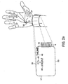
- FIG. 1 An illustrative embodiment of an apparatus of the invention and its placement on the users forearm 8 is shown in FIG. 1.
- the invention consists of two major components: a neuromuscular electrode 1 and an electronic monitor 2.
- the neuromuscular electrode 1 includes both a stimulator and a detector.
- the electronic monitor 2 includes both a controller and an indicator.
- the neuromuscular electrode 1 and electronic monitor 2 are physically separable with electrical connections between the two components established by physical contact between a connector 6, associated with the neuromuscular electrode 1 and connector slot 7 associated with the electronic monitor 2.
- neuromuscular electrode 1 and electronic monitor 2 constitute a single, physically inseparable unit.
- the electronic monitor 2 contains means to actuate the diagnostic process. Referring to the illustrative embodiment shown in FIG.
- a push-button 3 is provided to initiate said diagnostic process.
- the electronic monitor 2 also contains an indicator to display or convey the results of the diagnostic process.
- an indicator includes a display 4, which includes two multi-segment light-emitting diodes (LEDs) and which provides feedback and results.
- LEDs multi-segment light-emitting diodes
- Other indicators may be used, including, but not limited to, single and multicolor discrete LEDs.
- Other types of indicators, such as, for example, speakers, may provide auditory signals.
- the electronic monitor 2 also contains a communications port to connect and communicate with external devices. Referring to the illustrative embodiment shown in FIG. 1, the communications port includes a jack 5 into which a cable may be inserted. The other end of the cable is then connected to any number of different devices, including, but not limited to, computers and telephone lines.
- the neuromuscular electrode 1 delivers electrical stimuli to the skin surface, detects biopotentials from the skin surface and measures additional physiological and biological parameters, such as, for example, skin temperature.
- the neuromuscular electrode 1 is placed on the anterior aspect of the forearm 8 immediately proximal to the wrist crease 9.
- the physical dimensions of the neuromuscular electrode 1 are chosen from a predetermined set of dimensions which are optimized for the range of wrist sizes found in adults.
- the electrodes may be configured in a small, regular and large size.
- Additional embodiments are contemplated in which the neuromuscular electrode 1 includes means to vary its physical dimensions over a predetermined range, such as, for example, being contained in an electrode housing, such as, an adjustable band or strap.
- the band or strap may also be detachable.
- FIG. 2A An illustrative embodiment of the neuromuscular electrode 1 is shown in FIG. 2A.
- FIG. 2A shows the top surface of the neuromuscular electrode 1 and its proper location on the user's wrist.
- the top surface of the neuromuscular electrode 1 contains printed instructions 46 and/or other visual indications 45 to help the user properly position it.
- FIG. 2B shows the bottom surface of the neuromuscular electrode 1. The illustrative configuration allows muscle activity in the Thenar muscle group 51 to be evoked and sensed when the neuromuscular electrode 1 is positioned immediately proximal to the wrist crease 9, as shown in FIG. 2A.
- Two bioelectrical transduction sites, 30 and 31, hereafter referred to as the stimulation sites, are positioned approximately midway between the lateral end 19 and medial end 17 of the neuromuscular electrode 1.
- the two stimulation sites, 30 and 31, are arranged in a distal to proximal line such that one of the sites is near the distal end 18 of the neuromuscular electrode 1 and one of the sites is near the proximal end 20 of the neuromuscular electrode 1.
- the stimulation sites may consist of stimulation electrodes comprised of delineated areas of bioelectrical signal transduction means that convert electronic signals into electrochemical ones and vice versa.
- these sites are composed of a plurality of layers of different materials with substantially the same area.
- a first layer is directly attached to the bottom face of the neuromuscular electrode 1 and is preferably formed by a thin layer of silver.
- a second layer is attached to first layer and preferably consists of a silver-chloride salt.
- a third layer is attached to second layer and contacts the user's skin on its exposed surface.
- the third layer is preferably composed of an electrolyte hydrogel, such as, for example, sodium chloride.
- the two stimulation sites, 30 and 31, will overlie the Median nerve 50.
- the nerve 50 is stimulated by passing a low amplitude current (e.g ., typically less than 10 milliamps) through the two stimulation sites, 30 and 31.
- the current is provided by an external source electrically coupled to contacts, 34 and 35, on the external connector 6.
- the contacts, 34 and 35, and the stimulation sites, 30 and 31, are coupled by electrically conductive and insulated means, 32 and 33.
- the detection sites are positioned at the extreme lateral end 19 and medial end 17 of the neuromuscular electrode 1 near its distal end 18.
- the detection sites, 21 and 22 consist of detection electrodes comprised of delineated areas of bioelectrical signal transduction means that convert electronic signals into electrochemical ones and vice versa.
- these sites are constructed in a substantially similar manner to the stimulation sites, 30 and 31.
- Thenar muscles 51 will generate a myoelectric potential and create a bioelectrical potential difference between the lateral 21 and medial 22 detection sites due to the relative proximity of the lateral detection site 21 to the Thenar muscles 51.
- This potential difference may be measured as a small (e.g ., typically less than 0.5 mV) differential voltage between contacts, 25 and 26, on the external connector 6.
- the contacts, 25 and 26, and the detection sites, 21 and 22, are coupled by electrically conductive and insulated means, 23 and 24.
- the measurement of the differential voltage signal is enhanced by the availability of a reference potential, which is provided by transduction site 27, hereafter referred to as the reference site, or reference electrode.
- This site is positioned along the medial end 17 of the neuromuscular electrode 1 towards its proximal end 20.
- the position of the reference site 27 is, however, not critical and has relatively little effect on the function of the invention.
- the reference site 27 is constructed in a substantially similar manner to the stimulation sites, 30 and 31, and detection sites, 21 and 22.
- the reference potential is made available at a contact 29 on the external connector 6, which is coupled to the reference site 27 by electrically conductive and insulated means 28.
- the neuromuscular electrode 1 contains a temperature sensor 36, such as, for example, a DS 1820 (Dallas Semiconductor, Dallas, TX) or a thermistor.
- the temperature sensitive part of the sensor 36 contacts the users skin directly or indirectly through an intermediary material that efficiently conducts heat.
- the temperature sensor 36 can be placed at any available location within the area of the neuromuscular electrode 1.
- the temperature sensor 36 is powered and transmits temperature information to electronic monitor 2 through two or more contacts, 39 and 40, on the external connector 6.
- the contacts, 39 and 40, and the temperature sensor 36 are coupled by electrically conductive and insulated means, 37 and 38.
- transduction sites and sensors have been contemplated and should be considered within the scope of the present invention.
- One such configuration utilizes a single pair of transduction sites for both stimulation and detection through electronic multiplexing.
- the electronic monitor 2 has a number of functions.
- the monitor 2 detects, amplifies, processes and stores bioelectrical potentials, such as those generated by nerve or muscle activity. It also generates stimuli, such as steps of electrical current, with sufficient magnitude to trigger impulses in nerves or muscles. In addition, it communicates with the user and with external instruments, such as, for example, a personal computer.
- the electronic monitor 2 includes a controller to process data and control the intensity and duration of stimulus applications.
- FIG. 3 An illustrative block diagram of the electronic monitor 2 of FIG. 1 is shown in FIG. 3.
- Differential amplifier 60 amplifies the voltage difference between the input terminals and generates a voltage that is proportional to that voltage difference.
- the differential amplifier 60 of FIG. 3 is electrically coupled to detection sites, 21 and 22, and reference site 27. Since the bioelectrical signals from the body surface typically have a source impedance between about 5 K ⁇ to about 50 K ⁇ and contain large common mode signals, the differential amplifier 60 must have a high input impedance, a good common mode rejection ratio and a low leakage current. These requirements are preferably met by an instrumentation amplifier, such as, for example, the INA111 (Burr-Brown, Tuscon, AZ) or the AD621 (Analog Devices, Norwood, MA).
- an instrumentation amplifier such as, for example, the INA111 (Burr-Brown, Tuscon, AZ) or the AD621 (Analog Devices, Norwood, MA
- the differential amplifier 60 is electrically coupled to a signal conditioning unit 61 that prepares the signal for analog-to-digital conversion and subsequent processing.
- the signal conditioning unit 61 preferably removes DC offsets, amplifies, low-pass filters, and creates a DC bias.
- the signal conditioning unit 61 is electrically coupled to an analog-to-digital converter on the controller 63.
- Temperature sensor interface electronics 62 power the temperature sensor and convert temperature related signals into a form interpretable by controller 63.
- Stimulator 64 generates an electrical impulse with either or both of the magnitude and duration of the impulse being determined by signals from controller 63.
- the stimulator 64 is preferably embodied by a circuit which gates the discharge of a capacitor charged to a high voltage (e.g ., 100 volts).
- the capacitance value e.g ., 1 ⁇ F is chosen so that the discharge time constant (e.g ., several seconds) is much longer than the typical impulse duration ( e.g ., less than 1 millisecond).
- the voltage across the capacitor is established by internal charging means, such as, for example, a DC-DC converter. In another embodiment, it is established by external charging means. In the later case, the stimulator 64 is capable of generating a finite number of electrical impulses before it has to be recharged by the external charging means.
- Actuating means 65 are electrically coupled to processor 63 and preferably embodied by one or more push button switches.
- Indicator 66 is also electrically coupled to controller 63 and preferably embodied in a single, or multi-segment, LED.
- external interface 67 is electrically coupled to controller 63 and preferably embodied as a standard RS-232 serial interface.
- the controller 63 performs analog-to-digital conversion, senses and controls I/O lines, and processes, analyzes and stores acquired data.
- the controller 63 is preferably embodied as a single, integrated, low-cost embedded microcontroller. However, in other embodiments, the controller 63 is configured with multiple components, such as, for example, a microprocessor and external components that perform analog-to-digital conversion and other necessary functions.
- FIG. 4 shows a schematic diagram of the circuitry of one embodiment of the electronic monitor 2 of FIG. 1.
- the illustrative circuit of FIG. 4 includes a detection sub-circuit, a stimulation sub-circuit and a control and processing sub-circuit.
- the detection stage is based on amplifier U1 , a type INA111 (Burr-Brown, Arlington, AZ) instrumentation amplifier.
- Each of a pair of inputs of amplifier U1 , 100 and 101 is electrically coupled to one of the detector sites, 21 and 22, of FIG. 2B.
- amplifier U1 has a reference pin 102 at which it receives a reference potential through electrical coupling to reference site 27 of FIG. 2B.
- U1 is a monolithic instrumentation amplifier and requires one external component, a resistor, R7 , to establish its amplification gain, which is preferably a factor of 10.
- Amplifier U1 is powered by a two sided symmetrical power supply providing + Vc 110 and - Vc 111 ( e.g ., 6 volts), as well as a ground 112.
- + Vc 110, -Vc 111, and the ground 112 are provided by two batteries, B1 and B2, connected in series, as shown in FIG. 4.
- the output of amplifier U1 is coupled through a high pass filter formed by capacitor C1 and resistor R1 to the input of a non-inverting amplifier formed by operational amplifier U2a .
- the high pass filter removes any DC offset in the output of amplifier U1.
- capacitor C1 and resistor R1 are chosen for a high pass corner frequency of about 2 Hz.
- the gain of the non-inverting amplifier is established by resistors R2 and R10 and is preferably set to a gain of 500.
- the output of first operational amplifier U2a is coupled to input of second operational amplifier U2b by a low pass filter formed by resistor R3 and capacitor C2 .
- the low pass filter removes high frequency noise from the signal.
- resistor R3 and capacitor C2 are chosen for a low pass corner frequency of about 3 KHz.
- the second operational amplifier U2b is configured simply as an impedance buffer.
- the output of amplifier U2b is coupled to an analog-to-digital conversion pin on microcontroller U4 by a DC biasing circuit consisting of capacitor C4 , along with resistors R8 and R9 .
- the purpose of the DC biasing circuit is to insure that all signals vary from ground 112 to + Vc 110, since the analog-to-digital conversion electronics of microcontroller U4 operate only on positive voltages.
- the detection stage also has a combination communication and power line 116, for interfacing to a "one-wire" temperature sensor 36 of FIG. 2B, connected to an I/O pin on microcontroller U4.
- the stimulation sub-circuit of the apparatus is based on energy storage capacitor C3 , which is a high capacitance (e.g ., 1 ⁇ F or greater) and high voltage (e.g ., greater than 100 volts) capacitor.
- capacitor C3 is charged to greater than 100 volts by an external charging means 105.
- Capacitor C3 charging is accomplished by charging means 105, which passes electrical current between terminals 107 and 106, which are temporarily electrically coupled to capacitor C3 terminals 109 and 108 during the charging period. Once capacitor C3 is charged, charging means 105 is removed.
- Electrical stimulation of nerve and muscle is accomplished by discharging capacitor C3 through leads 103 and 104, which are electrically coupled to stimulation sites, 30 and 31. Control of stimulation duration is provided by a power MOSFET transistor Q1, which gates discharge according to a digital signal from microcontroller U4. Resistor R4 protects transistor Q1 by limiting the current that flows through it.
- microcontroller U4 which is preferably a type PIC12C71 (MicroChip, Chandler, AZ) microcontroller.
- U4 provides processing and storage capabilities, analog-to-digital conversion and input/output control.
- microcontroller U4 detects depression of switch S1, which is connected to an I/O pin and controls light emitting diode LED1, which is also connected to an I/O pin.
- Resistor R6 limits current into the I/O pin when switch S1 is depressed and resistor R5 limits current through the light-emitting diode LED1.
- serial communication 115 to external devices is provided by the remaining available I/O pin.
- Control and processing algorithms are stored in microcontroller U4 and executed automatically upon application of power.
- Other electronic circuitry may be used to perform the processes described above and is considered to be within the scope of the invention.
- One skilled in the art knows how to design electronic circuitry to perform the functions outlined above.
- a major object of the present invention is to serve as a detection system for CTS.
- Conventional detection of CTS is based on an analysis of certain features of the evoked muscle response, typically the distal motor latency (DML).
- the DML represents the time lag between stimulation of the Median nerve 50 immediately proximal to the wrist crease 9 and arrival of the neurally conducted impulse at the Thenar muscle group 51 after traversing the Carpal Tunnel.
- One of the most common and consistent indications of CTS is an increase in the DML.
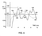
- the vertical scale 121 indicates the amplitude of the muscle response in millivolts as measured between detection sites 21 and 22.
- the large signal transients 123 that occur in the first 2 milliseconds represent stimulus associated artifacts and are unrelated to activity in the Thenar muscles 51.
- An evoked muscle response 120 may be characterized by many parameters including, but not limited to, a time to onset 124, a time to peak 125, a peak amplitude 126, a peak to peak amplitude 127 and a peak to peak width 128.
- the time to onset 124 is about 3.7 milliseconds
- the time to peak 125 is about 5.8 milliseconds.
- the intervening tissue acts as a low pass filter. This results in amplitude attenuation and temporal spreading of the detected waveform as compared to measurements taken directly over the Thenar muscles 51. The decrease in amplitude results in a reduction in the signal-to-noise ratio of the detected muscle response 120. The temporal spreading obscures sharp characteristic features of the response 120.
- analysis of the muscle response 120 is significantly enhanced by preprocessing it prior to determination of its characteristic features.
- One such preprocessing step is to take the second derivative of the muscle response 120 as shown in FIG. 6.
- the advantageous nature of this preprocessing step is evident from the fact that the second derivative 130 (solid line) has a peak 131 near the onset 124 of the muscle response 120. Consequently, it is possible to accurately and consistently obtain a latency estimate 133 by simply detecting the presence of this peak 131.
- a direct estimation of the time to onset 124 from the muscle response 120 requires establishment of an arbitrary voltage threshold which may vary significantly among different individuals.
- the sharp peak 131 in the second derivative 130 of FIG. 6 is obtained by first smoothing the muscle response 120, such as by, for example, convolving it with a normalized Gaussian waveform with a predetermined standard deviation. Subsequently, the first derivative is calculated by estimating the instantaneous slope for each data point in the muscle response 120. The second derivative is then calculated by estimating the instantaneous slope for each data point in the just computed first derivative. In order to conserve dynamic memory resources, the first and second derivatives 130 can be sequentially calculated for small sections of the muscle response 120 and the values discarded if they do not indicate the presence of a peak 131 in the second derivative 130.
- the largest positive peak within a defined time window 136 is selected.
- This time window 136 is defined as occurring between two time limits, 134 and 135.
- the lower time limit 134 is predetermined and reflects the amount of time required for artifacts 123 associated with the stimulus to decay to an amplitude that is significantly less than the amplitude of the actual signal evoked from the muscle 120.
- the lower time limit 134 is preferably about 2.5 milliseconds. Other lower time limits may, however, be used.
- the upper time limit 135 is determined dynamically.
- the upper time limit 135 is set to reflect the time during which the first derivative of the evoked muscle response 120 is positive. In other words, it reflects the period of time during which the evoked muscle response 120 is increasing. By establishing the upper time limit 135 in this fashion, large peaks 132 in the second derivative of the response 130, which occur in the latter portion of the response, are ignored and, therefore, do not result in incorrect estimates of the latency 133.
- FIG. 7 shows an illustrative algorithm for detecting CTS using an apparatus of the invention in an entirely automated fashion.
- the algorithm commences in process step 140 by activation of actuating means 65, such as, for example, by depression of a START switch S1. If the actuation means have been activated, the algorithm continues with process step 142. Otherwise process step 140 is continuously executed until the actuating means are activated.
- the root-mean-square (RMS) value of the noise is obtained in the absence of any electrical stimulation and compared against a predetermined threshold, n max . If the noise RMS is less than n max , the algorithm continues with process step 146.
- actuating means 65 such as, for example, by depression of a START switch S1.
- the algorithm proceeds to process step 144, in which indicator 66 is used to indicate a problem with the noise level to the user. Subsequently, the algorithm returns to process step 140 and waits for reactivation of the START switch S1.
- the magnitude of stimuli to be used in diagnosing CTS is determined.
- this parameter is determined automatically without user involvement. This is accomplished by gradually increasing the stimulation duration in predetermined increments (e.g ., 25 microseconds) until the evoked muscle response 120 meets one or more predetermined criteria.
- the stimulation duration is increased until the peak of the first derivative of the evoked muscle response 120 exceeds a predetermined threshold (e.g ., 0.1 mV/ms). If the proper stimulation duration is obtained, the algorithm proceeds from process step 148 to process step 152.
- the algorithm proceeds to process step 150, in which indicator 66 is used to indicate a problem with the determination of stimulation magnitude to the user. Subsequently, the algorithm returns to process step 140 and waits for reactivation of the START switch.
- the algorithm Upon determination of the proper stimulation magnitude, the algorithm proceeds with process step 152.
- the Median nerve 50 is stimulated at a predetermined rate (e.g ., 2 Hz) for a predetermined duration ( e . g ., 2 seconds).
- a predetermined rate e.g ., 2 Hz
- a predetermined duration e.g ., 2 seconds
- DML distal motor latency
- the plurality of DML estimates are combined to obtain a mean DML ( m ) and a standard deviation ( s ) about this mean.
- the algorithm then proceeds to process step 153 in which m and s are adjusted for variations in skin temperature.
- m corrected m uncorrected + K 1 ⁇ T + k 2
- S corrected S uncorrected + K 1 ⁇ T + k 2
- the corrected mean DML ( m corrected ) and standard deviation ( s corrected ) represent the expected values at room temperature ( i.e ., 25° C or 298° K).
- the skin temperature, as measured by the temperature sensor 36, is represented by the variable T .
- the values of constants k 1 and k 2 are determined by a temperature calibration process. In this process, multiple measurements of the mean DML are obtained at a variety of temperatures spanning the expected range of temperatures over which the invention is normally used ( e . g ., 25°C to 40° C). Subsequently, a linear regression is performed between the temperatures and the mean DML measurements.
- the constants k 1 and k 2 are determined directly from the regression coefficients.
- process step 154 in which the standard deviation of the DML measurements, s , is compared against a predetermined threshold, s min. If s is larger or equal to s min, process step 156 is executed. Process step 156 evaluates the number of times m and s have been determined. If these values have been calculated only once, the algorithm returns to process step 146, where determination of the proper stimulation level and all subsequent processing is repeated. If m and s have been determined twice, however, process step 158 is executed, resulting in indication of a diagnostic error to the user through indicator 66. Subsequently, the algorithm returns to process step 140 and waits for reactivation of the START switch S1.
- process step 160 the mean of the DML estimates, m , is compared against a first predetermined latency threshold, t normal . If m is less than t normal , the algorithm proceeds to process step 162, in which a normal (i.e., user does not have CTS) test result is indicated to user through indicator 66. Subsequently, the algorithm returns to process step 140 and waits for reactivation of the START switch S1.
- a normal i.e., user does not have CTS
- the algorithm proceeds with process step 164, in which the mean distal motor latency, m , is compared against a second predetermined latency value, t CTS. If m is greater than t CTS, the algorithm proceeds to process step 166, in which an abnormal (i.e ., user has CTS) test result is indicated to user through indicator 66. Subsequently, the algorithm returns to process step 140 and waits for reactivation of the START switch S1.
- the algorithm continues with process step 168.
- the Median nerve 150 is stimulated by pairs of electrical stimuli spaced apart at a predetermined temporal interval (e.g ., 3 milliseconds).
- a predetermined temporal interval e.g . 3 milliseconds.
- the difference between the DML estimated from the first and second stimuli is determined.
- the plurality of DML difference estimates are combined to obtain a mean DML difference ( m' ) and a standard deviation ( s' ) about this mean.
- the algorithm proceeds to process step 170 in which the mean DML difference, m' is compared against a predetermined threshold, t shift .
- process step 166 is executed, in which an abnormal test result is indicated to the user, as described above. If this inequality does not hold, then an unknown test result is indicated to user in process step 172. Subsequently, the algorithm returns to process step 140 and waits for activation of the START switch S1 .
- parameters other than the DML may be incorporated into the diagnostic algorithm.
- Illustrative parameters include: waveform features of the evoked muscle response 120, such as, for example, the amplitude and width.
- Additional illustrative parameters include waveform features of processed forms of the evoked muscle response 120, such as, for example, its derivatives, its Fourier transform, and other parameters derived from statistical analyses ( e.g ., principal component analysis).
- additional parameters are obtained by comparison of any of the above parameters at different stimulation levels.
- the apparatus of the present invention may be used to detect other forms of nerve disease and to evaluate neuromuscular blockade.
- the train-of-four (TOF) protocol which is commonly used to evaluate the degree of neuromuscular blockade in anesthetized patients, is readily implemented using an apparatus of the invention.
- a predetermined number usually four
- a predetermined rate e . g ., 2 Hz
- the ratio of the amplitude of the last of the plurality of muscle responses to be evoked is divided by the amplitude of the first of the plurality of muscle responses to be evoked. This ratio is recognized as a sensitive indicator of neuromuscular blockade.
- the disclosed invention provides a new approach to monitoring neuromuscular physiology. Apparatus and methods are described for the substantially automated and highly efficient measurement of many different parameters of neuromuscular physiology. These indicators may be used to detect Carpal Tunnel Syndrome (CTS) and other peripheral nerve diseases, as well as to monitor neuromuscular blockade caused by pathological, pharmacological and chemical means.
- CTS Carpal Tunnel Syndrome
- the invention possesses the significant advantage that, unlike conventional measurements of nerve conduction across the wrist, the disclosed invention provides for a single integrated neuromuscular electrode that is placed immediately proximal to the wrist ( i.e ., the wrist crease). This is a very familiar anatomic location and so the placement operation is rapidly and easily undertaken by most adults.
- the disclosed invention does not require placement of multiple sets of electrodes on both sides of the wrist, which is a difficult and error prone procedure for non-experts.
- An additional advantage of the disclosed invention emerges from the fact that the integrated neuromuscular electrodes may be manufactured as a low-cost, disposable item. Consequently, the possibility of cross-contamination among users of the apparatus is significantly reduced. Furthermore, the low-cost, and ease of use will promote frequent monitoring of neuromuscular disorders, such as CTS, providing the potential benefits of early detection and regular tracking of the disease.
- Another advantage of the present invention is that the process of evoking, detecting and processing neuromuscular signals is carried out in an entirely automated fashion, without requiring involvement of either the user of the apparatus or trained personnel.
- a further advantage of the present invention is that the smallest and fewest electrical stimuli consistent with an accurate diagnostic assessment are used. As a result, discomfort to the user is minimized and, in most cases, eliminated entirely.
Abstract
Description
- The invention relates to apparatus and methods for assessment of neuromuscular function. More specifically, the invention relates to apparatus and methods for diagnosing peripheral nerve and muscle pathologies based on assessments of neuromuscular function.
- There are many clinical and non-clinical situations that call for a rapid, reliable and low-cost assessments of neuromuscular function. Reliable and automated devices are needed to monitor neuromuscular function in surgical and intensive care settings. For example, muscle relaxants significantly improve surgical procedures and post-operative care by regulating the efficacy of nerve to muscle coupling through a process called neuromuscular blockade. They are, however, difficult to use in a safe and effective manner because of the wide variation and lack of predictability of patient responses to them. In another setting, an easy to use and reliable indicator would be beneficial in assessing potential contamination exposure situations by chemical agents. These agents disrupt neuromuscular function and effectively cause neuromuscular blockage, putting soldiers and civilians at risk.
- The most common causes of neuromuscular disruption are, however, related to pathologies of the peripheral nerves and muscles. Neuromuscular disorders, such as, for example, Carpal Tunnel Syndrome (CTS), are very common and well known to the general public. Despite their extensive impact on individuals and the health care system, detection and monitoring of such neuromuscular pathologies remains expensive, complicated, and highly underutilized.
- CTS is one of the most common forms of neuromuscular disease. The disease is thought to arise from compression of the Median nerve as it traverses the wrist. CTS often causes discomfort or loss of sensation in the hand, and, in severe cases, a nearly complete inability to use one's hands. Highly repetitive wrist movements, as well as certain medical conditions, such as, for example, diabetes, rheumatoid arthritis, thyroid disease, and pregnancy, are thought to be factors that contribute to the onset of CTS. In 1995, the US National Center for Health Statistics estimated that there were over 1.89 million cases of CTS in the United States alone.
- Effective prevention of CTS requires early detection and subsequent action. Unfortunately, the state of CTS diagnosis is rather poor. Even experienced physicians find it difficult to diagnose and stage the severity of CTS based on symptoms alone. The only objective way to detect CTS is to measure the transmission of neural signals across the wrist. The gold standard approach is a formal nerve conduction study by a clinical neurologist, but this clinical procedure has a number of important disadvantages. First, it is a time consuming process that requires the services of a medical expert, such as a neurologist. Second, the procedure is very costly (e.g., $600-$1000). Furthermore, it is not available in environments where early detection could significantly decrease the rate of CTS, such as the workplace where a significant number of causes of CTS appear. As a result of these disadvantages, formal electrophysiological evaluation of suspected CTS is used relatively infrequently, which decreases the likelihood of early detection and prevention.
- The prior art reveals a number of attempts to simplify the assessment of neuromuscular function, such as in diagnosing CTS, and to make such diagnostic measurements available to non-experts.
Rosier (U.S. Pat. No. 4,807,643 ) describes a portable device for measuring nerve conduction velocity in patients. This instrument has, however, several very important disadvantages. First, it requires placement of two sets of electrodes: one set at the stimulation site and one set at the detection site. Consequently, a skilled operator with a fairly sophisticated knowledge of nerve and muscle anatomy must ensure correct application of the device. Inappropriate placement of one or both of the electrode sets can lead to significant diagnostic errors. Second, the Rosier apparatus suffers from the disadvantage that it is not automated. In particular, it demands that the user of the device establish the magnitude of the electrical stimulus, as well as a response detection threshold. These parameters are difficult to determine a priori, and their rapid and correct establishment requires an advanced understanding of both neurophysiology and the detailed electronic operation of the apparatus. -
Spitz, et al. (U.S. Pat. No. 5,215,100 ) andLemmen (U.S. Pat. No. 5,327,902 ) have also attempted to enhance the earlier prior art. Specifically, they proposed systems that measure nerve conduction parameters between the arm or forearm and the hand, such as would be required for diagnosing CTS. In both cases, however, electrode supporting structures or fixtures were proposed that would substantially fix the positions at which the stimulation electrodes contact the arm and the detection electrodes contact the hand. Furthermore, these systems suffer, from several important disadvantages. First, both systems are rather large and bulky, because they include a supporting fixture for the arm and hand of an adult. This severely limits their portability and increases their cost. Second, these devices still require highly trained operators who can make the appropriate adjustments on the apparatus so as to insure electrode contact with the proper anatomical sites on the arm and hand. A third disadvantage of both systems is that they continue to demand multiple operator decisions regarding stimulation and detection parameters. Finally, these prior art systems suffer from the disadvantage that they do not automatically implement the diagnostic procedure and indicate the results in a simple and readily interpretable form. - There remains a need, therefore, for apparatus and methods for assessing neuromuscular function that are less time consuming, less expensive, and more available to a wider range of the general public (i.e., are more portable and easy to use). Such apparatus and methods are needed to provide more widespread early detection and prevention of neuromuscular pathologies, such as CTS. The present invention addresses these needs.
- The apparatus of the present invention is as claimed in
claim 1. The method of the present invention is as claim 7. Optional features are recited in the dependent claims. - In accordance with the invention, apparatus and methods are provided for the substantially automated, rapid, and efficient assessment of neuromuscular function without the involvement of highly trained personnel. Assessment of neuromuscular function occurs by stimulating a nerve, then measuring the response of a muscle innervated by that nerve. The muscle response is detected by measuring the myoelectric potential generated by the muscle in response to the stimulus. One indication of the physiological state of the nerve is provided by the delay between application of a stimulus and detection of a muscular response. If the nerve is damaged, conduction of the signal via the nerve to the muscle, and, hence, detection of the muscle's response, will be slower than in a healthy nerve. An abnormally high delay between stimulus application and detection of muscle response indicates, therefore, impaired neuromuscular function. In apparatus and methods of the invention, both the application of stimulus and the detection of responses is carried out entirely at a position that is immediately proximal to the wrist of an individual (i.e., the wrist crease). This anatomical location is familiar and easy to locate, thus ensuring correct placement of the apparatus at the assessment site by non-experts while still maintaining the accuracy of results. This ease of use increases the availability and decreases the cost of diagnosing pathologies such as Carpal Tunnel Syndrome (CTS).
- Apparatus and methods of the invention assess neuromuscular function in the arm of an individual by using a stimulator to apply a stimulus to a nerve that traverses the wrist of the individual. The stimulator is adapted for applying the stimulus to the nerve at a position which is proximal to the wrist of the individual. The stimulus may be, for example, an electrical stimulus or a magnetic stimulus. Other types of stimuli may be used. A detector, adapted for detecting the myoelectric potential generated by a muscle in response to the stimulus, detects the response of the muscle to the stimulus at a site that is also proximal to the wrist of the individual. A controller then evaluates the physiological function of the nerve by, for example, determining a delay between application of stimulus and detection of myoelectic potential. The delay is then correlated to the presence or absence of a neuromuscular pathology, such as, for example, Carpal Tunnel Syndrome (CTS).
- In a preferred embodiment, the stimulator and the detector are both in electrical communication with electrodes adapted for placement on the arm of an individual proximal to the wrist. The controller may also be in electrical communication with a reference electrode and a temperature sensor. An apparatus of the invention may further comprise a communications port for establishing communication between the apparatus and an external device, such as, for example, a personal computer.
- In another embodiment, an apparatus of the invention further comprises an indicator. The indicator is in electrical communication with the controller and is adapted for indicating the physiological function evaluated by the controller in response to the stimulus applied and myoelectic potential detected. The indicator may comprise a light emitting diode. In a particularly preferred embodiment, the indicator is adapted for indicating the presence or absence of CTS.
- An apparatus of the invention may be further embodied in an electrode configuration contained in an electrode housing for releasably securing to the wrist of an individual. The electrode housing contains an attachment mechanism, such as, for example, a non-irritating adhesive material, for securing to the arm of the individual and may be disposable. The electrode housing preferably has a connector for electrical communication with an apparatus comprising a stimulator, a detector, and a processor, as described above.
- The electrode housing comprises stimulation and detection electrodes. The stimulation and detection electrodes are sized and shaped in the housing so that they contact an anterior aspect of an arm of the individual proximal to the wrist, when the housing is secured to the wrist of the individual. The electrode configuration may further contain a temperature sensor and/or a reference electrode.
- In a preferred embodiment, the electrode configuration comprises a second stimulation electrode and a second detection electrode. The two stimulation electrodes are positioned substantially in the center of the electrode housing and are arranged so that they are positioned at opposite ends of the housing. The two stimulation electrodes are preferably arranged so that, when the housing is placed on the anterior aspect of an arm of a user, one of the stimulation electrodes is located immediately proximal to the wrist and the other at a location more proximal from the wrist. The two detection electrodes are also located at opposite ends of the housing, but they are positioned such that, when placed on the anterior aspect of an arm of a user, one detection electrode is located on the medial, and the other on the lateral, side of the wrist.
- Methods of the invention relate to the assessment of neuromuscular function using an apparatus of the invention. Using an apparatus, as described above, a stimulus is applied to a nerve that traverses the wrist of an individual proximal to the wrist. A muscle innervated by the nerve responds and thereby generates a myoelectric potential, which is detected proximal to the wrist of the individual. The detected response is processed by determining a first derivative of the myoelectric potential and, preferably, a second derivative of the myoelectric potential. In a preferred embodiment, these derivatives are used to determine an appropriate stimulation level, as well as to determine the delay between application of stimuli and detection of the associated responses. In another embodiment, additional measurements related to the delay are taken. For example, changes in the delay induced by application of at least two stimulus applications is determined. The delay and associated parameters calculated from any of the measurements are then correlated to a physiological function of the nerve and muscle.
- In preferred embodiments, an apparatus of the invention is used to indicate the presence or absence of CTS. A plurality of stimuli are applied to a nerve passing through the carpal tunnel, such as, for example, the Median nerve. The stimuli may be delivered one at a time at a predetermined rate or they may be delivered in pairs at a predetermined rate. If delivered in pairs, the application of stimuli is separated by a predetermined time interval.
- A plurality of myoelectric potentials are generated by a muscle innervated by the stimulated nerve in response to the stimuli. Each myoelectic potential is generated in response to a respective stimulus application. A delay for each of said stimulus applications and detected responses is determined. Statistics such as, for example, mean and standard deviation, are calculated for the plurality of delays. The probable value that the individual has CTS is calculated based on these statistics. An indication of the presence or absence of CTS is then given based on that value.
- In other embodiments of the invention, the method may involve further steps. For example, in one embodiment of the invention, the method relates to calculating the difference between delays measured in response to two stimuli delivered at short temporal intervals, and determining the probable value that an individual has CTS based on these delay differences and calculated statistics, as described above. In another embodiment, a level of noise is measured prior to stimulating the nerve. In yet another embodiment, the mean and standard deviation of the delays is adjusted relative to the skin temperature.
- An apparatus and method for the essentially automated and accurate assessment of neuromuscular function is therefore provided. The apparatus and methods of the invention allow for the less costly and more readily available detection of neuromuscular pathologies, such as, for example, CTS, without the aid of a skilled professional.
- The invention will be understood further upon consideration of the following drawings, description, and claims.
-
- Figure 1 is an illustration of an embodiment of the apparatus of the invention attached to the wrist of a user.
- Figure 2A shows a top surface of the embodiment of the apparatus of the invention shown in Fig. 1.
- Figure 2B illustrates a bottom surface of the embodiment of the apparatus of the invention shown in Fig. 1 depicting an electrode configuration.
- Figure 3 is a block diagram of an embodiment of the apparatus of the invention.
- Figure 4 illustrates electronic circuitry for an embodiment of an apparatus of the invention.
- Figure 5 is a graph showing a muscle response evoked and measured by an apparatus of the invention.
- Figure 6 is a graph showing a second derivative of a muscle response signal evoked and measured by an apparatus of the invention.
- Figure 7 is flow chart of an embodiment of an algorithm for detecting carpal tunnel syndrome using an apparatus of the invention.
- An illustrative embodiment of an apparatus of the invention and its placement on the
users forearm 8 is shown in FIG. 1. The invention consists of two major components: aneuromuscular electrode 1 and anelectronic monitor 2. Theneuromuscular electrode 1 includes both a stimulator and a detector. Theelectronic monitor 2 includes both a controller and an indicator. In this embodiment, theneuromuscular electrode 1 andelectronic monitor 2 are physically separable with electrical connections between the two components established by physical contact between aconnector 6, associated with theneuromuscular electrode 1 and connector slot 7 associated with theelectronic monitor 2. In another embodiment,neuromuscular electrode 1 andelectronic monitor 2 constitute a single, physically inseparable unit. Theelectronic monitor 2 contains means to actuate the diagnostic process. Referring to the illustrative embodiment shown in FIG. 1, a push-button 3 is provided to initiate said diagnostic process. Theelectronic monitor 2 also contains an indicator to display or convey the results of the diagnostic process. Referring to the illustrative embodiment shown in FIG. 1, an indicator includes adisplay 4, which includes two multi-segment light-emitting diodes (LEDs) and which provides feedback and results. Other indicators may be used, including, but not limited to, single and multicolor discrete LEDs. Other types of indicators, such as, for example, speakers, may provide auditory signals. Theelectronic monitor 2 also contains a communications port to connect and communicate with external devices. Referring to the illustrative embodiment shown in FIG. 1, the communications port includes ajack 5 into which a cable may be inserted. The other end of the cable is then connected to any number of different devices, including, but not limited to, computers and telephone lines. - The
neuromuscular electrode 1 delivers electrical stimuli to the skin surface, detects biopotentials from the skin surface and measures additional physiological and biological parameters, such as, for example, skin temperature. As shown in FIG. 1, theneuromuscular electrode 1 is placed on the anterior aspect of theforearm 8 immediately proximal to thewrist crease 9. In the preferred embodiment, the physical dimensions of theneuromuscular electrode 1 are chosen from a predetermined set of dimensions which are optimized for the range of wrist sizes found in adults. For example, the electrodes may be configured in a small, regular and large size. Additional embodiments are contemplated in which theneuromuscular electrode 1 includes means to vary its physical dimensions over a predetermined range, such as, for example, being contained in an electrode housing, such as, an adjustable band or strap. The band or strap may also be detachable. - An illustrative embodiment of the
neuromuscular electrode 1 is shown in FIG. 2A. FIG. 2A shows the top surface of theneuromuscular electrode 1 and its proper location on the user's wrist. In one embodiment, the top surface of theneuromuscular electrode 1 contains printedinstructions 46 and/or othervisual indications 45 to help the user properly position it. FIG. 2B shows the bottom surface of theneuromuscular electrode 1. The illustrative configuration allows muscle activity in theThenar muscle group 51 to be evoked and sensed when theneuromuscular electrode 1 is positioned immediately proximal to thewrist crease 9, as shown in FIG. 2A. Two bioelectrical transduction sites, 30 and 31, hereafter referred to as the stimulation sites, are positioned approximately midway between thelateral end 19 andmedial end 17 of theneuromuscular electrode 1. The two stimulation sites, 30 and 31, are arranged in a distal to proximal line such that one of the sites is near thedistal end 18 of theneuromuscular electrode 1 and one of the sites is near theproximal end 20 of theneuromuscular electrode 1. - The stimulation sites may consist of stimulation electrodes comprised of delineated areas of bioelectrical signal transduction means that convert electronic signals into electrochemical ones and vice versa. In a preferred embodiment, these sites are composed of a plurality of layers of different materials with substantially the same area. A first layer is directly attached to the bottom face of the
neuromuscular electrode 1 and is preferably formed by a thin layer of silver. A second layer is attached to first layer and preferably consists of a silver-chloride salt. A third layer is attached to second layer and contacts the user's skin on its exposed surface. The third layer is preferably composed of an electrolyte hydrogel, such as, for example, sodium chloride. - When the
neuromuscular electrode 1 is properly positioned as shown in FIG. 2A, the two stimulation sites, 30 and 31, will overlie theMedian nerve 50. Thenerve 50 is stimulated by passing a low amplitude current (e.g., typically less than 10 milliamps) through the two stimulation sites, 30 and 31. The current is provided by an external source electrically coupled to contacts, 34 and 35, on theexternal connector 6. The contacts, 34 and 35, and the stimulation sites, 30 and 31, are coupled by electrically conductive and insulated means, 32 and 33. - Two transduction sites, 21 and 22, hereafter referred to as the detection sites, are positioned at the extreme
lateral end 19 andmedial end 17 of theneuromuscular electrode 1 near itsdistal end 18. In a preferred embodiment, the detection sites, 21 and 22, consist of detection electrodes comprised of delineated areas of bioelectrical signal transduction means that convert electronic signals into electrochemical ones and vice versa. In a preferred embodiment, these sites are constructed in a substantially similar manner to the stimulation sites, 30 and 31. - Contraction of the
Thenar muscles 51 will generate a myoelectric potential and create a bioelectrical potential difference between the lateral 21 and medial 22 detection sites due to the relative proximity of thelateral detection site 21 to theThenar muscles 51. This potential difference may be measured as a small (e.g., typically less than 0.5 mV) differential voltage between contacts, 25 and 26, on theexternal connector 6. The contacts, 25 and 26, and the detection sites, 21 and 22, are coupled by electrically conductive and insulated means, 23 and 24. The measurement of the differential voltage signal is enhanced by the availability of a reference potential, which is provided bytransduction site 27, hereafter referred to as the reference site, or reference electrode. This site is positioned along themedial end 17 of theneuromuscular electrode 1 towards itsproximal end 20. The position of thereference site 27 is, however, not critical and has relatively little effect on the function of the invention. In a preferred embodiment, thereference site 27 is constructed in a substantially similar manner to the stimulation sites, 30 and 31, and detection sites, 21 and 22. The reference potential is made available at acontact 29 on theexternal connector 6, which is coupled to thereference site 27 by electrically conductive andinsulated means 28. - The
neuromuscular electrode 1 contains atemperature sensor 36, such as, for example, a DS 1820 (Dallas Semiconductor, Dallas, TX) or a thermistor. The temperature sensitive part of thesensor 36 contacts the users skin directly or indirectly through an intermediary material that efficiently conducts heat. Thetemperature sensor 36 can be placed at any available location within the area of theneuromuscular electrode 1. Thetemperature sensor 36 is powered and transmits temperature information toelectronic monitor 2 through two or more contacts, 39 and 40, on theexternal connector 6. The contacts, 39 and 40, and thetemperature sensor 36 are coupled by electrically conductive and insulated means, 37 and 38. - Additional configurations and arrangements of transduction sites and sensors have been contemplated and should be considered within the scope of the present invention. One such configuration utilizes a single pair of transduction sites for both stimulation and detection through electronic multiplexing.
- The
electronic monitor 2 has a number of functions. Themonitor 2 detects, amplifies, processes and stores bioelectrical potentials, such as those generated by nerve or muscle activity. It also generates stimuli, such as steps of electrical current, with sufficient magnitude to trigger impulses in nerves or muscles. In addition, it communicates with the user and with external instruments, such as, for example, a personal computer. Finally, theelectronic monitor 2 includes a controller to process data and control the intensity and duration of stimulus applications. - An illustrative block diagram of the
electronic monitor 2 of FIG. 1 is shown in FIG. 3.Differential amplifier 60 amplifies the voltage difference between the input terminals and generates a voltage that is proportional to that voltage difference. When theelectronic monitor 2 andneuromuscular electrode 1 of FIG. 1 are connected by physical contact between connectors, 6 and 7, thedifferential amplifier 60 of FIG. 3 is electrically coupled to detection sites, 21 and 22, andreference site 27. Since the bioelectrical signals from the body surface typically have a source impedance between about 5 KΩ to about 50 KΩ and contain large common mode signals, thedifferential amplifier 60 must have a high input impedance, a good common mode rejection ratio and a low leakage current. These requirements are preferably met by an instrumentation amplifier, such as, for example, the INA111 (Burr-Brown, Tuscon, AZ) or the AD621 (Analog Devices, Norwood, MA). - The
differential amplifier 60 is electrically coupled to asignal conditioning unit 61 that prepares the signal for analog-to-digital conversion and subsequent processing. Thesignal conditioning unit 61 preferably removes DC offsets, amplifies, low-pass filters, and creates a DC bias. Thesignal conditioning unit 61 is electrically coupled to an analog-to-digital converter on thecontroller 63. - Temperature
sensor interface electronics 62 power the temperature sensor and convert temperature related signals into a form interpretable bycontroller 63.Stimulator 64 generates an electrical impulse with either or both of the magnitude and duration of the impulse being determined by signals fromcontroller 63. - The
stimulator 64 is preferably embodied by a circuit which gates the discharge of a capacitor charged to a high voltage (e.g., 100 volts). The capacitance value (e.g., 1 µF is chosen so that the discharge time constant (e.g., several seconds) is much longer than the typical impulse duration (e.g., less than 1 millisecond). The voltage across the capacitor is established by internal charging means, such as, for example, a DC-DC converter. In another embodiment, it is established by external charging means. In the later case, thestimulator 64 is capable of generating a finite number of electrical impulses before it has to be recharged by the external charging means. - Actuating means 65 are electrically coupled to
processor 63 and preferably embodied by one or more push button switches.Indicator 66 is also electrically coupled tocontroller 63 and preferably embodied in a single, or multi-segment, LED. Finally,external interface 67 is electrically coupled tocontroller 63 and preferably embodied as a standard RS-232 serial interface. Thecontroller 63 performs analog-to-digital conversion, senses and controls I/O lines, and processes, analyzes and stores acquired data. Thecontroller 63 is preferably embodied as a single, integrated, low-cost embedded microcontroller. However, in other embodiments, thecontroller 63 is configured with multiple components, such as, for example, a microprocessor and external components that perform analog-to-digital conversion and other necessary functions. - FIG. 4 shows a schematic diagram of the circuitry of one embodiment of the
electronic monitor 2 of FIG. 1. The illustrative circuit of FIG. 4 includes a detection sub-circuit, a stimulation sub-circuit and a control and processing sub-circuit. The detection stage is based on amplifier U1, a type INA111 (Burr-Brown, Tucson, AZ) instrumentation amplifier. Each of a pair of inputs of amplifier U1, 100 and 101, is electrically coupled to one of the detector sites, 21 and 22, of FIG. 2B. In addition, amplifier U1 has areference pin 102 at which it receives a reference potential through electrical coupling toreference site 27 of FIG. 2B. U1 is a monolithic instrumentation amplifier and requires one external component, a resistor, R7, to establish its amplification gain, which is preferably a factor of 10. Amplifier U1 is powered by a two sided symmetrical power supply providing +Vc 110 and - Vc 111 (e.g., 6 volts), as well as aground 112. In a preferred embodiment, +Vc 110, -Vc 111, and theground 112 are provided by two batteries, B1 and B2, connected in series, as shown in FIG. 4. The output of amplifier U1 is coupled through a high pass filter formed by capacitor C1 and resistor R1 to the input of a non-inverting amplifier formed by operational amplifier U2a. The high pass filter removes any DC offset in the output of amplifier U1. In a preferred embodiment, capacitor C1 and resistor R1 are chosen for a high pass corner frequency of about 2 Hz. The gain of the non-inverting amplifier is established by resistors R2 and R10 and is preferably set to a gain of 500. The output of first operational amplifier U2a is coupled to input of second operational amplifier U2b by a low pass filter formed by resistor R3 and capacitor C2. The low pass filter removes high frequency noise from the signal. In a preferred embodiment, resistor R3 and capacitor C2 are chosen for a low pass corner frequency of about 3 KHz. The second operational amplifier U2b is configured simply as an impedance buffer. The output of amplifier U2b is coupled to an analog-to-digital conversion pin on microcontroller U4 by a DC biasing circuit consisting of capacitor C4, along with resistors R8 and R9. The purpose of the DC biasing circuit is to insure that all signals vary fromground 112 to +Vc 110, since the analog-to-digital conversion electronics of microcontroller U4 operate only on positive voltages. The detection stage also has a combination communication and power line 116, for interfacing to a "one-wire"temperature sensor 36 of FIG. 2B, connected to an I/O pin on microcontroller U4. - The stimulation sub-circuit of the apparatus is based on energy storage capacitor C3, which is a high capacitance (e.g., 1 µF or greater) and high voltage (e.g., greater than 100 volts) capacitor. In one embodiment of the apparatus, capacitor C3 is charged to greater than 100 volts by an external charging means 105. Capacitor C3 charging is accomplished by charging
means 105, which passes electrical current betweenterminals capacitor C3 terminals leads - The control and processing stages of the apparatus are based on microcontroller U4, which is preferably a type PIC12C71 (MicroChip, Chandler, AZ) microcontroller. U4 provides processing and storage capabilities, analog-to-digital conversion and input/output control. In addition to the aforementioned connections to detection and stimulation subcircuits, microcontroller U4 detects depression of switch S1, which is connected to an I/O pin and controls light emitting diode LED1, which is also connected to an I/O pin. Resistor R6 limits current into the I/O pin when switch S1 is depressed and resistor R5 limits current through the light-emitting diode LED1. In addition,
serial communication 115 to external devices is provided by the remaining available I/O pin. Control and processing algorithms are stored in microcontroller U4 and executed automatically upon application of power. Other electronic circuitry may be used to perform the processes described above and is considered to be within the scope of the invention. One skilled in the art knows how to design electronic circuitry to perform the functions outlined above. - A major object of the present invention is to serve as a detection system for CTS. Conventional detection of CTS is based on an analysis of certain features of the evoked muscle response, typically the distal motor latency (DML). The DML represents the time lag between stimulation of the
Median nerve 50 immediately proximal to thewrist crease 9 and arrival of the neurally conducted impulse at theThenar muscle group 51 after traversing the Carpal Tunnel. One of the most common and consistent indications of CTS is an increase in the DML. Although there is no single definition for the DML, it is generally defined as the amount of time that elapses between the start of the stimulus (i.e., time = 0) and the occurrence of a consistent feature on the muscle response. - A
typical muscle response 120, evoked and acquired using an apparatus of the invention, is shown in FIG. 5. Thevertical scale 121 indicates the amplitude of the muscle response in millivolts as measured betweendetection sites horizontal scale 122 indicates the elapsed time from the onset of the stimulation pulse (i.e., stimulus occurred at time = 0). Thelarge signal transients 123 that occur in the first 2 milliseconds represent stimulus associated artifacts and are unrelated to activity in theThenar muscles 51. An evokedmuscle response 120 may be characterized by many parameters including, but not limited to, a time toonset 124, a time to peak 125, apeak amplitude 126, a peak to peakamplitude 127 and a peak to peakwidth 128. In the illustrative example of FIG. 5, the time toonset 124 is about 3.7 milliseconds, and the time to peak 125 is about 5.8 milliseconds. - Because detection of the
Thenar muscle 51 response occurs at a significant distance from its physiological site of origin, the intervening tissue acts as a low pass filter. This results in amplitude attenuation and temporal spreading of the detected waveform as compared to measurements taken directly over theThenar muscles 51. The decrease in amplitude results in a reduction in the signal-to-noise ratio of the detectedmuscle response 120. The temporal spreading obscures sharp characteristic features of theresponse 120. Taken together these two low-pass related effects make a consistent and accurate identification of muscle response features, such as the time toonset 124 or the time to peak 125, difficult and highly variable, especially in the presence of various noise sources (e.g., extraneous muscle activity such as would be caused by a muscle twitch in an arm muscle). - In a preferred embodiment, analysis of the
muscle response 120 is significantly enhanced by preprocessing it prior to determination of its characteristic features. One such preprocessing step is to take the second derivative of themuscle response 120 as shown in FIG. 6. The advantageous nature of this preprocessing step is evident from the fact that the second derivative 130 (solid line) has apeak 131 near theonset 124 of themuscle response 120. Consequently, it is possible to accurately and consistently obtain alatency estimate 133 by simply detecting the presence of thispeak 131. By contrast, a direct estimation of the time toonset 124 from themuscle response 120 requires establishment of an arbitrary voltage threshold which may vary significantly among different individuals. - In a preferred embodiment, the
sharp peak 131 in thesecond derivative 130 of FIG. 6 is obtained by first smoothing themuscle response 120, such as by, for example, convolving it with a normalized Gaussian waveform with a predetermined standard deviation. Subsequently, the first derivative is calculated by estimating the instantaneous slope for each data point in themuscle response 120. The second derivative is then calculated by estimating the instantaneous slope for each data point in the just computed first derivative. In order to conserve dynamic memory resources, the first andsecond derivatives 130 can be sequentially calculated for small sections of themuscle response 120 and the values discarded if they do not indicate the presence of a peak 131 in thesecond derivative 130. - Once the
peaks 131 in the second derivative 130 have been identified, the largest positive peak within a definedtime window 136 is selected. Thistime window 136 is defined as occurring between two time limits, 134 and 135. In a preferred embodiment, thelower time limit 134 is predetermined and reflects the amount of time required forartifacts 123 associated with the stimulus to decay to an amplitude that is significantly less than the amplitude of the actual signal evoked from themuscle 120. Thelower time limit 134 is preferably about 2.5 milliseconds. Other lower time limits may, however, be used. In addition, it is possible to dynamically establish thelower time limit 134 by analyzing the amplitude decay of the stimulus associatedartifact 123. Theupper time limit 135 is determined dynamically. In a preferred embodiment, theupper time limit 135 is set to reflect the time during which the first derivative of the evokedmuscle response 120 is positive. In other words, it reflects the period of time during which the evokedmuscle response 120 is increasing. By establishing theupper time limit 135 in this fashion,large peaks 132 in the second derivative of theresponse 130, which occur in the latter portion of the response, are ignored and, therefore, do not result in incorrect estimates of thelatency 133. - In accordance with a preferred embodiment of the present invention, FIG. 7 shows an illustrative algorithm for detecting CTS using an apparatus of the invention in an entirely automated fashion. The algorithm commences in
process step 140 by activation of actuating means 65, such as, for example, by depression of a START switch S1. If the actuation means have been activated, the algorithm continues withprocess step 142. Otherwiseprocess step 140 is continuously executed until the actuating means are activated. Inprocess step 142, the root-mean-square (RMS) value of the noise is obtained in the absence of any electrical stimulation and compared against a predetermined threshold, nmax. If the noise RMS is less than nmax , the algorithm continues withprocess step 146. However, if the noise RMS is greater than nmax , the algorithm proceeds to processstep 144, in whichindicator 66 is used to indicate a problem with the noise level to the user. Subsequently, the algorithm returns to processstep 140 and waits for reactivation of the START switch S1. - In
process step 146, the magnitude of stimuli to be used in diagnosing CTS is determined. In a preferred process, this parameter is determined automatically without user involvement. This is accomplished by gradually increasing the stimulation duration in predetermined increments (e.g., 25 microseconds) until the evokedmuscle response 120 meets one or more predetermined criteria. As an illustrative example, the stimulation duration is increased until the peak of the first derivative of the evokedmuscle response 120 exceeds a predetermined threshold (e.g., 0.1 mV/ms). If the proper stimulation duration is obtained, the algorithm proceeds fromprocess step 148 to processstep 152. If a proper stimulation magnitude is not obtained, (i.e., predetermined threshold not exceeded) the algorithm proceeds to processstep 150, in whichindicator 66 is used to indicate a problem with the determination of stimulation magnitude to the user. Subsequently, the algorithm returns to processstep 140 and waits for reactivation of the START switch. - Upon determination of the proper stimulation magnitude, the algorithm proceeds with
process step 152. In this step, theMedian nerve 50 is stimulated at a predetermined rate (e.g., 2 Hz) for a predetermined duration (e.g., 2 seconds). EachThenar muscle response 120 is analyzed, as previously described, to estimate the distal motor latency (DML) as the firstmajor peak 133 of thesecond derivative 130 of themuscle response 120. Furthermore, the plurality of DML estimates are combined to obtain a mean DML (m) and a standard deviation (s) about this mean. The algorithm then proceeds to processstep 153 in which m and s are adjusted for variations in skin temperature. In particular, the following two adjustment equations are applied:

The corrected mean DML (mcorrected ) and standard deviation (scorrected ) represent the expected values at room temperature (i.e., 25° C or 298° K). The skin temperature, as measured by thetemperature sensor 36, is represented by the variable T. The values of constants k1 and k2 are determined by a temperature calibration process. In this process, multiple measurements of the mean DML are obtained at a variety of temperatures spanning the expected range of temperatures over which the invention is normally used (e.g., 25°C to 40° C). Subsequently, a linear regression is performed between the temperatures and the mean DML measurements. The constants k1 and k2 are determined directly from the regression coefficients. - The algorithm then continues with
process step 154, in which the standard deviation of the DML measurements, s, is compared against a predetermined threshold, smin. If s is larger or equal to smin, process step 156 is executed.Process step 156 evaluates the number of times m and s have been determined. If these values have been calculated only once, the algorithm returns to processstep 146, where determination of the proper stimulation level and all subsequent processing is repeated. If m and s have been determined twice, however,process step 158 is executed, resulting in indication of a diagnostic error to the user throughindicator 66. Subsequently, the algorithm returns to processstep 140 and waits for reactivation of the START switch S1. - If in
process step 154 it is determined that s is less than smin , the algorithm proceeds withprocess step 160. In this step, the mean of the DML estimates, m, is compared against a first predetermined latency threshold, tnormal . If m is less than tnormal , the algorithm proceeds to processstep 162, in which a normal (i.e., user does not have CTS) test result is indicated to user throughindicator 66. Subsequently, the algorithm returns to processstep 140 and waits for reactivation of the START switch S1. If m is greater or equal to tnormal , the algorithm proceeds withprocess step 164, in which the mean distal motor latency, m, is compared against a second predetermined latency value, tCTS. If m is greater than tCTS, the algorithm proceeds to processstep 166, in which an abnormal (i.e., user has CTS) test result is indicated to user throughindicator 66. Subsequently, the algorithm returns to processstep 140 and waits for reactivation of the START switch S1. - If neither of the two previous inequalities is true, the algorithm continues with
process step 168. In this step, theMedian nerve 150 is stimulated by pairs of electrical stimuli spaced apart at a predetermined temporal interval (e.g., 3 milliseconds). For each evokedmuscle response 120, the difference between the DML estimated from the first and second stimuli is determined. Furthermore, the plurality of DML difference estimates are combined to obtain a mean DML difference (m') and a standard deviation (s') about this mean. Upon measurement of these two parameters, the algorithm proceeds to processstep 170 in which the mean DML difference, m' is compared against a predetermined threshold, tshift. If m' is greater than tshift ,process step 166 is executed, in which an abnormal test result is indicated to the user, as described above. If this inequality does not hold, then an unknown test result is indicated to user inprocess step 172. Subsequently, the algorithm returns to processstep 140 and waits for activation of the START switch S1. - The aforementioned algorithm is intended for illustrative purposes only. Other algorithms may be developed which detect CTS using an apparatus of the invention. For example, parameters other than the DML may be incorporated into the diagnostic algorithm. Illustrative parameters include: waveform features of the evoked
muscle response 120, such as, for example, the amplitude and width. Additional illustrative parameters include waveform features of processed forms of the evokedmuscle response 120, such as, for example, its derivatives, its Fourier transform, and other parameters derived from statistical analyses (e.g., principal component analysis). Furthermore, additional parameters are obtained by comparison of any of the above parameters at different stimulation levels. - Although the illustrative algorithms described above pertain to the detection of CTS, the apparatus of the present invention may used to detect other forms of nerve disease and to evaluate neuromuscular blockade. For example, the train-of-four (TOF) protocol, which is commonly used to evaluate the degree of neuromuscular blockade in anesthetized patients, is readily implemented using an apparatus of the invention. In particular, a predetermined number (usually four) of
muscle responses 120 are evoked at a predetermined rate (e.g., 2 Hz) and theamplitude 126 of each response determined. Subsequently, the ratio of the amplitude of the last of the plurality of muscle responses to be evoked is divided by the amplitude of the first of the plurality of muscle responses to be evoked. This ratio is recognized as a sensitive indicator of neuromuscular blockade. - The disclosed invention provides a new approach to monitoring neuromuscular physiology. Apparatus and methods are described for the substantially automated and highly efficient measurement of many different parameters of neuromuscular physiology. These indicators may be used to detect Carpal Tunnel Syndrome (CTS) and other peripheral nerve diseases, as well as to monitor neuromuscular blockade caused by pathological, pharmacological and chemical means. The invention possesses the significant advantage that, unlike conventional measurements of nerve conduction across the wrist, the disclosed invention provides for a single integrated neuromuscular electrode that is placed immediately proximal to the wrist (i.e., the wrist crease). This is a very familiar anatomic location and so the placement operation is rapidly and easily undertaken by most adults. Unlike apparatus and methods of the prior art, the disclosed invention does not require placement of multiple sets of electrodes on both sides of the wrist, which is a difficult and error prone procedure for non-experts. An additional advantage of the disclosed invention emerges from the fact that the integrated neuromuscular electrodes may be manufactured as a low-cost, disposable item. Consequently, the possibility of cross-contamination among users of the apparatus is significantly reduced. Furthermore, the low-cost, and ease of use will promote frequent monitoring of neuromuscular disorders, such as CTS, providing the potential benefits of early detection and regular tracking of the disease. Another advantage of the present invention is that the process of evoking, detecting and processing neuromuscular signals is carried out in an entirely automated fashion, without requiring involvement of either the user of the apparatus or trained personnel. A further advantage of the present invention is that the smallest and fewest electrical stimuli consistent with an accurate diagnostic assessment are used. As a result, discomfort to the user is minimized and, in most cases, eliminated entirely.
- While the present invention has been described in terms of certain exemplary preferred embodiments, it will be readily understood and appreciated by one of ordinary skill in the art that it is not so limited, and that many additions, deletions and modifications to the preferred embodiments may be made within the scope of the invention as hereinafter claimed. Accordingly, the scope of the invention is limited only by the scope of the appended claims.
Claims (8)
- An apparatus for assessing a physiological function in an arm and a hand of an individual, comprising:a stimulator (30) for producing and applying a stimulus, a detector (22) for detecting a myoelectric potential and a controller (2), wherein:the apparatus is configured so as to be releasably securable to the arm of the individual substantially proximal the wrist of the individual and the stimulator (30) and detector (22) are positioned on the apparatus such that when the apparatus is secured to the forearm (8) of the individual substantially proximal the wrist of the individual the stimulator (30) is located proximal to said wrist whereby application of said stimulus stimulates a nerve (50) that traverses said wrist; and the detector (22) is located proximal to said wrist whereby said myoelectric potential is generated by a muscle (5) in communication with said nerve in said hand of said individual in response to said stimulus; andthe controller (2) is arranged to evaluate a physiological function in response to said stimulus and said myoelectric potential.
- The apparatus of claim 1, wherein said controller (2) is further arranged to determine a delay between application of said stimulus and detection of said myoelectric potential and, optionally,
said controller (2) is further arranged to correlate said delay to the presence or absence of carpal tunnel syndrome. - The apparatus of claim 1, wherein said stimulus is an electrical stimulus or a magnetic stimulus.
- The apparatus of claim 1, further comprising any of:a) a stimulation electrode in electrical communication with said stimulator (30);b) a detection electrode in electrical communication with said detector (22);c) a reference electrode (27) positioned for placement on said arm proximal to said wrist and in electrical communication with said controller;d) a temperature sensor (36) in electrical communication with said controller;e) an indicator in electrical communication with said controller and arranged to receive indicia from said controller (2) and indicating said physiological function, in which case, optionally, either:i) said indicator is further arranged to indicate the presence of absence of carpal tunnel syndrome, orii) said indicator comprises a light emitting diode; andf) a communications port arranged to establish communication between said apparatus and an external device.
- The apparatus of claim 1, in which
the stimulator includes a stimulation electrode (30);
the detector includes a detection electrode (22);
and wherein said electrodes (30, 22) are sized and shaped for positioning on an anterior aspect of said arm (8) of said individual, and comprise an electrode configuration for assessing neuromuscular functions in an arm of said individual. - The apparatus of claim 5, and any of:a) the electrode configuration further comprising a temperature sensor (36);b) the electrode configuration, further comprising a reference electrode (27);c) said stimulation electrode (30) and said detection electrode (22) are contained in an electrode housing, in which case, optionally, any of:i) said electrode housing is adapted for placement on said arm (8) of said individual substantially proximal to said wrist, in which case, further optionally,
further comprising a second stimulation electrode (31), in which case, further optionally, either:α) said stimulation electrode (30) and said second stimulation electrode (31) are positioned substantially in the center of said electrode housing; orβ) said stimulation electrode (30) and said second stimulation electrode (30) and said second stimulation electrode (31) are arranged such that one of said stimulation electrodes is positioned at one end of said electrode housing and the other of said stimulation electrodes is positioned at the opposite end of said electrode housing, such that, when said electrode housing is placed on said anterior aspect of said arm, one of said stimulation electrodes is located immediately proximal to said wrist and the other of said stimulation electrodes is located at a position more proximal from said wrist;ii) the electrode configuration further comprising a second detection electrode (26); and optionally said detection electrode (25) and said second detection electrode (26) are arranged such that one of said detection electrodes is positioned at one end of said electrode housing and the other of said detection electrodes is positioned at the opposite end of said electrode housing, such that, when said electrode housing is placed on said anterior aspect of said arm, one of said detection electrodes is located near the medial side of said arm and the other of said detection electrodes is located near the lateral side of said arm;iii) the electrode configuration further comprising an attachment mechanism for securing said electrode housing to said arm of said individual; andiv) said electrode housing comprises a connector adapted for electrical communication with an apparatus of claim 1; or said electrode housing is disposable. - A method of assessing nerve conduction parameters in an arm of an individual, comprising the steps of:a) applying a stimulus proximal to a wrist of said individual, whereby application of said stimulus stimulates a a nerve that traverses said wrist;b) detecting a myoelectric potential proximal to the wrist of the individual, said myoelectric potential being generated by a muscle in the hand of said individual in response to said stimulus, said muscle being in communication with said nerve;c) processing said stimulus and said myoelectric potential to obtain processing results; andd) evaluating said nerve conduction parameters based on said processing results.
- The method of claim 7, and any of:a) the method further comprising the step of indicating the results of said evaluating step, in which case, optionally,
said indicating step further comprising the step of indicating the differences between said nerve conduction parameters and an expected value;b) said processing step further comprises the step of determining a delay between application of said stimulus and detection of said myoelectric potential, in which case, optionally,
said step of determining a delay between application of said stimulus and detection of said myoelectric potential comprises the step of determining a second derivative of said myoelectric potential;c) the method further comprising the step of determining a first derivative of said myoelectric potential, in which case, optionally,
further comprising the step of repeating steps a) and b) of claim 7 at incrementally increasing stimulus durations until said first derivative for one of said myoelectric potentials exceeds a predetermined level;d) said evaluating step further comprises the step of comparing said nerve conduction parameters to an expected value; ande) further comprising the step of determining a delay between application of said stimulus and detection of said myoelectric potential for at least two stimulus applications and comparing the delays determined in response to application of each of said at least two stimulus applications.
Applications Claiming Priority (3)
| Application Number | Priority Date | Filing Date | Title |
|---|---|---|---|
| US886861 | 1997-07-01 | ||
| US08/886,861 US5851191A (en) | 1997-07-01 | 1997-07-01 | Apparatus and methods for assessment of neuromuscular function |
| PCT/US1998/012922 WO1999001064A1 (en) | 1997-07-01 | 1998-06-22 | Apparatus and methods for assessment of neuromuscular function |
Publications (2)
| Publication Number | Publication Date |
|---|---|
| EP0993270A1 EP0993270A1 (en) | 2000-04-19 |
| EP0993270B1 true EP0993270B1 (en) | 2007-10-10 |
Family
ID=25389937
Family Applications (1)
| Application Number | Title | Priority Date | Filing Date |
|---|---|---|---|
| EP98931451A Expired - Lifetime EP0993270B1 (en) | 1997-07-01 | 1998-06-22 | Apparatus and methods for assessment of neuromuscular function |
Country Status (8)
| Country | Link |
|---|---|
| US (3) | US5851191A (en) |
| EP (1) | EP0993270B1 (en) |
| JP (2) | JP3657277B2 (en) |
| AT (1) | ATE375116T1 (en) |
| AU (1) | AU750315B2 (en) |
| CA (1) | CA2295132C (en) |
| DE (1) | DE69838549D1 (en) |
| WO (1) | WO1999001064A1 (en) |
Families Citing this family (159)
| Publication number | Priority date | Publication date | Assignee | Title |
|---|---|---|---|---|
| US6132386A (en) * | 1997-07-01 | 2000-10-17 | Neurometrix, Inc. | Methods for the assessment of neuromuscular function by F-wave latency |
| US7628761B2 (en) * | 1997-07-01 | 2009-12-08 | Neurometrix, Inc. | Apparatus and method for performing nerve conduction studies with localization of evoked responses |
| US6564078B1 (en) | 1998-12-23 | 2003-05-13 | Nuvasive, Inc. | Nerve surveillance cannula systems |
| WO2000038574A1 (en) | 1998-12-23 | 2000-07-06 | Nuvasive, Inc. | Nerve surveillance cannulae systems |
| AU3187000A (en) | 1999-03-07 | 2000-09-28 | Discure Ltd. | Method and apparatus for computerized surgery |
| WO2000076400A1 (en) * | 1999-06-14 | 2000-12-21 | Agee, John M., Trustee Of The John M. Agee Trust Dated August 15, 1996 | Method and apparatus for monitoring tendon motion |
| DE69938660D1 (en) * | 1999-10-29 | 2008-06-19 | Compex Medical Sa | Neuromuscular stimulation device with recording of the muscle reaction to the electrical stimulation pulse |
| US6466817B1 (en) * | 1999-11-24 | 2002-10-15 | Nuvasive, Inc. | Nerve proximity and status detection system and method |
| JP4854900B2 (en) * | 1999-11-24 | 2012-01-18 | ヌバシブ, インコーポレイテッド | EMG measurement method |
| US20020055688A1 (en) * | 2000-05-18 | 2002-05-09 | Jefferson Jacob Katims | Nervous tissue stimulation device and method |
| WO2001087154A1 (en) | 2000-05-18 | 2001-11-22 | Nuvasive, Inc. | Tissue discrimination and applications in medical procedures |
| EP1292223A2 (en) | 2000-06-08 | 2003-03-19 | Nuvasive, Inc. | Relative nerve movement and status detection system and method |
| US6564079B1 (en) | 2000-07-27 | 2003-05-13 | Ckm Diagnostics, Inc. | Electrode array and skin attachment system for noninvasive nerve location and imaging device |
| US20030105503A1 (en) * | 2001-06-08 | 2003-06-05 | Nuvasive, Inc. | Relative nerve movement and status detection system and method |
| EP1417000B1 (en) | 2001-07-11 | 2018-07-11 | Nuvasive, Inc. | System for determining nerve proximity during surgery |
| EP1435828A4 (en) | 2001-09-25 | 2009-11-11 | Nuvasive Inc | System and methods for performing surgical procedures and assessments |
| US7664544B2 (en) | 2002-10-30 | 2010-02-16 | Nuvasive, Inc. | System and methods for performing percutaneous pedicle integrity assessments |
| US6829510B2 (en) * | 2001-12-18 | 2004-12-07 | Ness Neuromuscular Electrical Stimulation Systems Ltd. | Surface neuroprosthetic device having an internal cushion interface system |
| US8147421B2 (en) | 2003-01-15 | 2012-04-03 | Nuvasive, Inc. | System and methods for determining nerve direction to a surgical instrument |
| US7582058B1 (en) | 2002-06-26 | 2009-09-01 | Nuvasive, Inc. | Surgical access system and related methods |
| US8137284B2 (en) | 2002-10-08 | 2012-03-20 | Nuvasive, Inc. | Surgical access system and related methods |
| US7691057B2 (en) | 2003-01-16 | 2010-04-06 | Nuvasive, Inc. | Surgical access system and related methods |
| US9462960B2 (en) * | 2003-02-21 | 2016-10-11 | 3Dt Holdings, Llc | Impedance devices and methods of using the same to obtain luminal organ measurements |
| US7819801B2 (en) | 2003-02-27 | 2010-10-26 | Nuvasive, Inc. | Surgical access system and related methods |
| US20040225228A1 (en) | 2003-05-08 | 2004-11-11 | Ferree Bret A. | Neurophysiological apparatus and procedures |
| JP4436836B2 (en) | 2003-08-05 | 2010-03-24 | ヌヴァシヴ インコーポレイテッド | System and method for performing dynamic pedicle integrity assessment |
| US7179231B2 (en) * | 2003-08-25 | 2007-02-20 | Wisys Technology Foundation, Inc., | Apparatus and method for analyzing nerve conduction |
| EP1680177B1 (en) | 2003-09-25 | 2017-04-12 | NuVasive, Inc. | Surgical access system |
| US7905840B2 (en) | 2003-10-17 | 2011-03-15 | Nuvasive, Inc. | Surgical access system and related methods |
| SE0302746D0 (en) * | 2003-10-17 | 2003-10-17 | Uppsala Laekarkonsult Ab | multielectrode |
| US8313430B1 (en) | 2006-01-11 | 2012-11-20 | Nuvasive, Inc. | Surgical access system and related methods |
| US8326410B2 (en) * | 2004-02-17 | 2012-12-04 | Neurometrix, Inc. | Method for automated analysis of submaximal F-waves |
| WO2007022524A2 (en) | 2005-08-19 | 2007-02-22 | Neuronetrix, Inc. | Controller for neuromuscular testing |
| US9622732B2 (en) | 2004-10-08 | 2017-04-18 | Nuvasive, Inc. | Surgical access system and related methods |
| US9247952B2 (en) | 2004-10-15 | 2016-02-02 | Amendia, Inc. | Devices and methods for tissue access |
| US20100331883A1 (en) | 2004-10-15 | 2010-12-30 | Schmitz Gregory P | Access and tissue modification systems and methods |
| US7578819B2 (en) | 2005-05-16 | 2009-08-25 | Baxano, Inc. | Spinal access and neural localization |
| US7938830B2 (en) | 2004-10-15 | 2011-05-10 | Baxano, Inc. | Powered tissue modification devices and methods |
| US8062300B2 (en) | 2006-05-04 | 2011-11-22 | Baxano, Inc. | Tissue removal with at least partially flexible devices |
| US7738969B2 (en) | 2004-10-15 | 2010-06-15 | Baxano, Inc. | Devices and methods for selective surgical removal of tissue |
| US8192435B2 (en) | 2004-10-15 | 2012-06-05 | Baxano, Inc. | Devices and methods for tissue modification |
| US7963915B2 (en) | 2004-10-15 | 2011-06-21 | Baxano, Inc. | Devices and methods for tissue access |
| US8430881B2 (en) | 2004-10-15 | 2013-04-30 | Baxano, Inc. | Mechanical tissue modification devices and methods |
| US8613745B2 (en) | 2004-10-15 | 2013-12-24 | Baxano Surgical, Inc. | Methods, systems and devices for carpal tunnel release |
| US9101386B2 (en) | 2004-10-15 | 2015-08-11 | Amendia, Inc. | Devices and methods for treating tissue |
| US8048080B2 (en) | 2004-10-15 | 2011-11-01 | Baxano, Inc. | Flexible tissue rasp |
| US20110190772A1 (en) | 2004-10-15 | 2011-08-04 | Vahid Saadat | Powered tissue modification devices and methods |
| US8221397B2 (en) | 2004-10-15 | 2012-07-17 | Baxano, Inc. | Devices and methods for tissue modification |
| US7887538B2 (en) | 2005-10-15 | 2011-02-15 | Baxano, Inc. | Methods and apparatus for tissue modification |
| US8257356B2 (en) | 2004-10-15 | 2012-09-04 | Baxano, Inc. | Guidewire exchange systems to treat spinal stenosis |
| EP1656883A1 (en) * | 2004-11-10 | 2006-05-17 | Universite Libre De Bruxelles | Portable device for measuring EMG signal |
| US7785253B1 (en) | 2005-01-31 | 2010-08-31 | Nuvasive, Inc. | Surgical access system and related methods |
| US7643884B2 (en) | 2005-01-31 | 2010-01-05 | Warsaw Orthopedic, Inc. | Electrically insulated surgical needle assembly |
| US20060173374A1 (en) * | 2005-01-31 | 2006-08-03 | Neubardt Seth L | Electrically insulated surgical probing tool |
| EP2409641B1 (en) | 2005-02-02 | 2017-07-05 | NuVasive, Inc. | System for performing neurophysiologic assessments during spine surgery |
| US8568331B2 (en) | 2005-02-02 | 2013-10-29 | Nuvasive, Inc. | System and methods for monitoring during anterior surgery |
| US7424322B2 (en) * | 2005-02-03 | 2008-09-09 | Cardinal Health 209, Inc. | Method and apparatus for stimulus artifact suppression |
| US20060178594A1 (en) * | 2005-02-07 | 2006-08-10 | Neubardt Seth L | Apparatus and method for locating defects in bone tissue |
| US8092455B2 (en) | 2005-02-07 | 2012-01-10 | Warsaw Orthopedic, Inc. | Device and method for operating a tool relative to bone tissue and detecting neural elements |
| US20060200023A1 (en) * | 2005-03-04 | 2006-09-07 | Sdgi Holdings, Inc. | Instruments and methods for nerve monitoring in spinal surgical procedures |
| US20070185409A1 (en) * | 2005-04-20 | 2007-08-09 | Jianping Wu | Method and system for determining an operable stimulus intensity for nerve conduction testing |
| US20070129771A1 (en) * | 2005-04-20 | 2007-06-07 | Kurtz Ronald L | Device, method and stimulus unit for testing neuromuscular function |
| US20060253167A1 (en) * | 2005-04-20 | 2006-11-09 | Kurtz Ronald L | Device, method and stimulus unit for testing neuromuscular function |
| US7640057B2 (en) * | 2005-04-25 | 2009-12-29 | Cardiac Pacemakers, Inc. | Methods of providing neural markers for sensed autonomic nervous system activity |
| WO2006119532A1 (en) * | 2005-05-13 | 2006-11-16 | Mcleay, Charmaine, A., M. | Detection of muscular disorders |
| US8740783B2 (en) | 2005-07-20 | 2014-06-03 | Nuvasive, Inc. | System and methods for performing neurophysiologic assessments with pressure monitoring |
| EP1912578B1 (en) | 2005-07-28 | 2018-02-07 | NuVasive, Inc. | Total disc replacement system |
| US8206312B2 (en) | 2005-09-22 | 2012-06-26 | Nuvasive, Inc. | Multi-channel stimulation threshold detection algorithm for use in neurophysiology monitoring |
| US8568317B1 (en) | 2005-09-27 | 2013-10-29 | Nuvasive, Inc. | System and methods for nerve monitoring |
| US8062298B2 (en) | 2005-10-15 | 2011-11-22 | Baxano, Inc. | Flexible tissue removal devices and methods |
| US20080086034A1 (en) | 2006-08-29 | 2008-04-10 | Baxano, Inc. | Tissue Access Guidewire System and Method |
| US8366712B2 (en) | 2005-10-15 | 2013-02-05 | Baxano, Inc. | Multiple pathways for spinal nerve root decompression from a single access point |
| US8092456B2 (en) | 2005-10-15 | 2012-01-10 | Baxano, Inc. | Multiple pathways for spinal nerve root decompression from a single access point |
| US9014798B2 (en) * | 2005-10-20 | 2015-04-21 | Neurometrix, Inc. | Automated stimulus artifact removal for nerve conduction studies |
| US7632239B2 (en) * | 2005-11-16 | 2009-12-15 | Bioness Neuromodulation Ltd. | Sensor device for gait enhancement |
| JP4738159B2 (en) * | 2005-12-12 | 2011-08-03 | 株式会社Ihi | Electromyography device for myoelectric potential measurement |
| US20070149892A1 (en) * | 2005-12-22 | 2007-06-28 | Neurotron Medical Inc. | Apparatus for neuromuscular function signal acquisition |
| US20100168501A1 (en) * | 2006-10-02 | 2010-07-01 | Daniel Rogers Burnett | Method and apparatus for magnetic induction therapy |
| US9610459B2 (en) * | 2009-07-24 | 2017-04-04 | Emkinetics, Inc. | Cooling systems and methods for conductive coils |
| US9339641B2 (en) * | 2006-01-17 | 2016-05-17 | Emkinetics, Inc. | Method and apparatus for transdermal stimulation over the palmar and plantar surfaces |
| WO2011053607A1 (en) | 2009-10-26 | 2011-05-05 | Emkinetics, Inc. | Method and apparatus for electromagnetic stimulation of nerve, muscle, and body tissues |
| EP2586489B1 (en) | 2006-05-01 | 2014-12-24 | Bioness Neuromodulation Ltd | Improved functional electrical stimulation systems |
| US20090077877A1 (en) * | 2006-08-08 | 2009-03-26 | Richard Kerber | Method and apparatus for precluding plant trunks from freezing |
| US7917201B2 (en) * | 2006-08-23 | 2011-03-29 | Neurometrix, Inc. | Method and apparatus for determining optimal neuromuscular detection sites, novel diagnostic biosensor array formed in accordance with the same, and novel method for testing a patient using the novel diagnostic biosensor array |
| CA2664172C (en) * | 2006-09-16 | 2016-03-29 | Terence Gilhuly | Improved sensors and sensing for monitoring neuromuscular blockade |
| US10786669B2 (en) | 2006-10-02 | 2020-09-29 | Emkinetics, Inc. | Method and apparatus for transdermal stimulation over the palmar and plantar surfaces |
| US9005102B2 (en) | 2006-10-02 | 2015-04-14 | Emkinetics, Inc. | Method and apparatus for electrical stimulation therapy |
| US11224742B2 (en) | 2006-10-02 | 2022-01-18 | Emkinetics, Inc. | Methods and devices for performing electrical stimulation to treat various conditions |
| US20080281378A1 (en) * | 2006-12-15 | 2008-11-13 | Michael Williams | Neurological diagnostic and therapeutic system utilizing function-specific modules |
| JP5005331B2 (en) * | 2006-12-19 | 2012-08-22 | 富士重工業株式会社 | Muscle force sensor |
| US8374673B2 (en) | 2007-01-25 | 2013-02-12 | Warsaw Orthopedic, Inc. | Integrated surgical navigational and neuromonitoring system having automated surgical assistance and control |
| US7987001B2 (en) | 2007-01-25 | 2011-07-26 | Warsaw Orthopedic, Inc. | Surgical navigational and neuromonitoring instrument |
| US20080183074A1 (en) * | 2007-01-25 | 2008-07-31 | Warsaw Orthopedic, Inc. | Method and apparatus for coordinated display of anatomical and neuromonitoring information |
| US8255045B2 (en) * | 2007-04-03 | 2012-08-28 | Nuvasive, Inc. | Neurophysiologic monitoring system |
| US9042978B2 (en) * | 2007-05-11 | 2015-05-26 | Neurometrix, Inc. | Method and apparatus for quantitative nerve localization |
| WO2009032363A1 (en) | 2007-09-06 | 2009-03-12 | Baxano, Inc. | Method, system and apparatus for neural localization |
| US8192436B2 (en) | 2007-12-07 | 2012-06-05 | Baxano, Inc. | Tissue modification devices |
| US8398641B2 (en) | 2008-07-01 | 2013-03-19 | Baxano, Inc. | Tissue modification devices and methods |
| US8409206B2 (en) | 2008-07-01 | 2013-04-02 | Baxano, Inc. | Tissue modification devices and methods |
| US9314253B2 (en) | 2008-07-01 | 2016-04-19 | Amendia, Inc. | Tissue modification devices and methods |
| CA2730732A1 (en) | 2008-07-14 | 2010-01-21 | Baxano, Inc. | Tissue modification devices |
| US8271659B2 (en) * | 2008-09-04 | 2012-09-18 | Oracle International Corporation | Methods and systems for automatic removal and replacement of connections in a pool rendered stale by a firewall |
| EP2369983B8 (en) * | 2008-11-18 | 2020-12-16 | Philips Healthcare Informatics, Inc. | Methods and apparatus for measurement of cardiovascular quantities |
| US9084551B2 (en) | 2008-12-08 | 2015-07-21 | Medtronic Xomed, Inc. | Method and system for monitoring a nerve |
| EP2381871A4 (en) | 2008-12-26 | 2013-03-20 | Scott Spann | Minimally-invasive retroperitoneal lateral approach for spinal surgery |
| US20100210965A1 (en) * | 2009-02-13 | 2010-08-19 | Gozani Shai N | Apparatus and method for the detection of neuromuscular signals |
| EP2405823A4 (en) | 2009-03-13 | 2012-07-04 | Baxano Inc | Flexible neural localization devices and methods |
| US8287597B1 (en) | 2009-04-16 | 2012-10-16 | Nuvasive, Inc. | Method and apparatus for performing spine surgery |
| US9351845B1 (en) | 2009-04-16 | 2016-05-31 | Nuvasive, Inc. | Method and apparatus for performing spine surgery |
| WO2010136946A2 (en) * | 2009-05-29 | 2010-12-02 | Koninklijke Philips Electronics N.V. | Capacitive sensing apparatus |
| US8394102B2 (en) | 2009-06-25 | 2013-03-12 | Baxano, Inc. | Surgical tools for treatment of spinal stenosis |
| US20110230785A1 (en) * | 2010-03-16 | 2011-09-22 | ProNerve, LLC | Somatosensory Evoked Potential (SSEP) Automated Alert System |
| US9775531B2 (en) * | 2010-06-09 | 2017-10-03 | Techmedic Development International B.V. | Sensor device, processing device, and measurement system for acquiring a biopotential |
| US10004445B2 (en) | 2010-09-16 | 2018-06-26 | Neurometrix, Inc. | Apparatus and method for stimulator on-skin short detection |
| WO2012037527A2 (en) | 2010-09-16 | 2012-03-22 | Neurometrix, Inc. | Apparatus and method for the automated measurement of sural nerve conduction velocity and amplitude |
| US9392953B1 (en) | 2010-09-17 | 2016-07-19 | Nuvasive, Inc. | Neurophysiologic monitoring |
| US9095417B2 (en) | 2011-02-07 | 2015-08-04 | Bioness Neuromodulation Ltd. | Adjustable orthosis for electrical stimulation of a limb |
| US8790406B1 (en) | 2011-04-01 | 2014-07-29 | William D. Smith | Systems and methods for performing spine surgery |
| US9974455B2 (en) | 2011-05-13 | 2018-05-22 | Saluda Medical Pty Ltd. | Method and apparatus for estimating neural recruitment |
| CA2835486C (en) | 2011-05-13 | 2022-07-19 | Saluda Medical Pty Limited | Method and apparatus for measurement of neural response - a |
| WO2012155185A1 (en) | 2011-05-13 | 2012-11-22 | National Ict Australia Ltd | Method and apparatus for measurement of neural response |
| US8868217B2 (en) | 2011-06-27 | 2014-10-21 | Bioness Neuromodulation Ltd. | Electrode for muscle stimulation |
| WO2013028571A1 (en) | 2011-08-19 | 2013-02-28 | Lanx, Inc. | Surgical retractor system and methods of use |
| US9198765B1 (en) | 2011-10-31 | 2015-12-01 | Nuvasive, Inc. | Expandable spinal fusion implants and related methods |
| CA2862869A1 (en) * | 2012-01-27 | 2013-08-01 | T4 Analytics Llc | Methods and systems for assessing muscle electrical activity in response to stimulation of a motor nerve |
| WO2013112853A1 (en) * | 2012-01-27 | 2013-08-01 | T4 Analytics Llc | Anesthesia monitoring systems and methods of monitoring anesthesia |
| US11877860B2 (en) | 2012-11-06 | 2024-01-23 | Nuvasive, Inc. | Systems and methods for performing neurophysiologic monitoring during spine surgery |
| US11259737B2 (en) | 2012-11-06 | 2022-03-01 | Nuvasive, Inc. | Systems and methods for performing neurophysiologic monitoring during spine surgery |
| US9757067B1 (en) | 2012-11-09 | 2017-09-12 | Nuvasive, Inc. | Systems and methods for performing neurophysiologic monitoring during spine surgery |
| US9841183B2 (en) | 2012-12-05 | 2017-12-12 | No Eul Kim | Electrode boiler with electrodes unit |
| US9757072B1 (en) | 2013-02-11 | 2017-09-12 | Nuvasive, Inc. | Waveform marker placement algorithm for use in neurophysiologic monitoring |
| EP4241688A3 (en) * | 2013-02-15 | 2023-11-22 | Senzime AB (publ.) | Electrode systems for use with medical monitoring systems |
| US10098585B2 (en) | 2013-03-15 | 2018-10-16 | Cadwell Laboratories, Inc. | Neuromonitoring systems and methods |
| JP2016515869A (en) * | 2013-03-15 | 2016-06-02 | エムキネティクス,インコーポレイテッド | Method and apparatus for transcutaneous stimulation on palm and plantar surfaces |
| US9867985B2 (en) | 2014-03-24 | 2018-01-16 | Bioness Inc. | Systems and apparatus for gait modulation and methods of use |
| US10420480B1 (en) | 2014-09-16 | 2019-09-24 | Nuvasive, Inc. | Systems and methods for performing neurophysiologic monitoring |
| EP3218046B1 (en) | 2014-12-11 | 2024-04-17 | Saluda Medical Pty Ltd | Device and computer program for feedback control of neural stimulation |
| EP3957356A1 (en) | 2015-04-09 | 2022-02-23 | Saluda Medical Pty Limited | Electrode to nerve distance estimation |
| AU2017206723B2 (en) | 2016-01-11 | 2021-11-25 | Bioness Inc. | Systems and apparatus for gait modulation and methods of use |
| JP7278076B2 (en) | 2016-06-24 | 2023-05-19 | サルーダ・メディカル・ピーティーワイ・リミテッド | Nerve stimulation to reduce artifacts |
| KR102657506B1 (en) * | 2016-10-14 | 2024-04-15 | 브링크 디바이스, 엘엘씨 | Apparatus, Method, and System for Processing Neuromusculature Signals |
| US10188346B2 (en) | 2016-10-27 | 2019-01-29 | Focal Wellness, Inc. | Cubital tunnel infomatic monitor |
| US9808208B1 (en) * | 2016-10-27 | 2017-11-07 | Focal Wellness, Inc. | Carpal tunnel infomatic monitor |
| US9935395B1 (en) | 2017-01-23 | 2018-04-03 | Cadwell Laboratories, Inc. | Mass connection plate for electrical connectors |
| US10758801B1 (en) | 2017-02-11 | 2020-09-01 | Focal Wellness, Inc. | Method and system for proper kicking technique |
| US10874347B1 (en) | 2017-03-02 | 2020-12-29 | Focal Wellness, Inc. | Multiple plane sensors |
| US11051737B2 (en) * | 2017-05-19 | 2021-07-06 | Ricoh Company, Ltd. | Biomagnetic measurement method, biomagnetic measuring device, and biomagnetic measuring system |
| KR102432861B1 (en) * | 2017-06-15 | 2022-08-16 | 삼성전자주식회사 | Image sensor for distance measuring |
| USD837394S1 (en) | 2017-07-11 | 2019-01-01 | Neurometrix, Inc. | Transcutaneous electrical nerve stimulation (TENS) device |
| USD865986S1 (en) | 2017-09-21 | 2019-11-05 | Neurometrix, Inc. | Transcutaneous electrical nerve stimulation device strap |
| USD857910S1 (en) | 2017-09-21 | 2019-08-27 | Neurometrix, Inc. | Transcutaneous electrical nerve stimulation device |
| WO2019204884A1 (en) | 2018-04-27 | 2019-10-31 | Saluda Medical Pty Ltd | Neurostimulation of mixed nerves |
| US11253182B2 (en) | 2018-05-04 | 2022-02-22 | Cadwell Laboratories, Inc. | Apparatus and method for polyphasic multi-output constant-current and constant-voltage neurophysiological stimulation |
| USD861903S1 (en) | 2018-05-15 | 2019-10-01 | Neurometrix, Inc. | Apparatus for transcutaneous electrical nerve stimulation |
| US11166648B2 (en) * | 2018-05-24 | 2021-11-09 | General Electric Company | Method and system for estimating patient recovery time utilizing neuromuscular transmission measurements |
| US11443649B2 (en) | 2018-06-29 | 2022-09-13 | Cadwell Laboratories, Inc. | Neurophysiological monitoring training simulator |
| US11612344B2 (en) | 2018-11-02 | 2023-03-28 | Biocircuit Technologies, Inc. | Electrode-based systems and devices for interfacing with biological tissue and related methods |
| US11382564B2 (en) * | 2018-12-28 | 2022-07-12 | Jose Antonio Gamboa-Pinto | Medical monitoring system with a foot diagnostic device |
| JP2022071585A (en) | 2020-10-28 | 2022-05-16 | キヤノン株式会社 | Photoelectric conversion apparatus, photoelectric conversion system, and moving body |
Family Cites Families (29)
| Publication number | Priority date | Publication date | Assignee | Title |
|---|---|---|---|---|
| US3572322A (en) * | 1968-10-11 | 1971-03-23 | Hoffmann La Roche | Transducer assembly |
| AT325196B (en) * | 1971-12-01 | 1975-10-10 | Rodler Ing Hans | ELECTRICAL DIAGNOSTIC DEVICE |
| US4213467A (en) * | 1978-08-11 | 1980-07-22 | Harvard College, President And Fellows | Monitoring myoelectric signals |
| US4291705A (en) * | 1979-09-10 | 1981-09-29 | The Regents Of The University Of California | Neuromuscular block monitor |
| US4807643A (en) * | 1982-08-16 | 1989-02-28 | University Of Iowa Research Foundation | Digital electroneurometer |
| FI73878C (en) * | 1983-06-10 | 1987-12-10 | Instrumentarium Oy | FOERFARANDE FOER VIDAREUTVECKLING AV NERVMUSKELANSLUTNINGS MAETNING. |
| US4811742A (en) * | 1985-06-11 | 1989-03-14 | Verimed, Inc. | Proportional response electrical muscle stimulation |
| US4763666A (en) * | 1986-04-22 | 1988-08-16 | Max-Planck-Gesellschaft Zur Foerderung Der Wissenschaften E.V. | Method and apparatus for determining the thermal sensitivity of the human peripheral nervous system |
| US5080099A (en) * | 1988-08-26 | 1992-01-14 | Cardiotronics, Inc. | Multi-pad, multi-function electrode |
| US5099844A (en) * | 1988-12-22 | 1992-03-31 | Biofield Corp. | Discriminant function analysis method and apparatus for disease diagnosis and screening |
| US5511553A (en) * | 1989-02-15 | 1996-04-30 | Segalowitz; Jacob | Device-system and method for monitoring multiple physiological parameters (MMPP) continuously and simultaneously |
| US5050612A (en) * | 1989-09-12 | 1991-09-24 | Matsumura Kenneth N | Device for computer-assisted monitoring of the body |
| DE3939790C1 (en) * | 1989-12-01 | 1991-02-28 | Draegerwerk Ag, 2400 Luebeck, De | |
| NL9000983A (en) * | 1990-04-24 | 1991-11-18 | Univ Nijmegen | APPARATUS AND METHOD FOR DETERMINING THE INFLUENCE OF ANESTHETICS ON HUMANS OR ANIMALS. |
| US5143081A (en) * | 1990-07-27 | 1992-09-01 | New York University | Randomized double pulse stimulus and paired event analysis |
| US5131401A (en) * | 1990-09-10 | 1992-07-21 | Axon Medical Inc. | Method and apparatus for monitoring neuromuscular blockage |
| US5092344A (en) * | 1990-11-19 | 1992-03-03 | Lee Tzium Shou | Remote indicator for stimulator |
| US5255677A (en) * | 1991-02-26 | 1993-10-26 | Vickers Plc | Disposable electrodes for electromyography (EMG) and nerve conduction velocity (NCV) and kit containing same |
| US5203330A (en) * | 1991-02-26 | 1993-04-20 | Vickers Plc | Disposable electrodes for electromyography (EMG) and nerve conduction velocity (NCV) and kit containing same |
| US5215100A (en) * | 1991-04-29 | 1993-06-01 | Occupational Preventive Diagnostic, Inc. | Nerve condition monitoring system and electrode supporting structure |
| FR2698008A1 (en) * | 1992-11-13 | 1994-05-20 | Mcadams Eric | Multifunction device with multiple electrodes and use of this device. |
| US5379764A (en) * | 1992-12-09 | 1995-01-10 | Diasense, Inc. | Non-invasive determination of analyte concentration in body of mammals |
| US5467768A (en) * | 1993-03-17 | 1995-11-21 | Nihon Koden Corporation | Multi-purpose sensor |
| US5327902A (en) * | 1993-05-14 | 1994-07-12 | Lemmen Roger D | Apparatus for use in nerve conduction studies |
| US5496363A (en) * | 1993-06-02 | 1996-03-05 | Minnesota Mining And Manufacturing Company | Electrode and assembly |
| US5333618A (en) * | 1993-06-30 | 1994-08-02 | Gregory Lekhtman | Portable self-contained instrument for the measurement of nerve resistance of a patient |
| US5560372A (en) * | 1994-02-02 | 1996-10-01 | Cory; Philip C. | Non-invasive, peripheral nerve mapping device and method of use |
| US5540235A (en) * | 1994-06-30 | 1996-07-30 | Wilson; John R. | Adaptor for neurophysiological monitoring with a personal computer |
| US6132386A (en) * | 1997-07-01 | 2000-10-17 | Neurometrix, Inc. | Methods for the assessment of neuromuscular function by F-wave latency |
-
1997
- 1997-07-01 US US08/886,861 patent/US5851191A/en not_active Expired - Lifetime
-
1998
- 1998-02-12 US US09/022,990 patent/US5976094A/en not_active Expired - Lifetime
- 1998-06-22 AU AU81579/98A patent/AU750315B2/en not_active Ceased
- 1998-06-22 EP EP98931451A patent/EP0993270B1/en not_active Expired - Lifetime
- 1998-06-22 AT AT98931451T patent/ATE375116T1/en not_active IP Right Cessation
- 1998-06-22 DE DE69838549T patent/DE69838549D1/en not_active Expired - Lifetime
- 1998-06-22 JP JP50721299A patent/JP3657277B2/en not_active Expired - Fee Related
- 1998-06-22 CA CA002295132A patent/CA2295132C/en not_active Expired - Fee Related
- 1998-06-22 WO PCT/US1998/012922 patent/WO1999001064A1/en active IP Right Grant
-
2004
- 2004-04-06 JP JP2004112602A patent/JP4324001B2/en not_active Expired - Fee Related
-
2008
- 2008-03-14 US US12/077,077 patent/US20090030337A1/en not_active Abandoned
Also Published As
| Publication number | Publication date |
|---|---|
| US20090030337A1 (en) | 2009-01-29 |
| CA2295132A1 (en) | 1999-01-14 |
| US5976094A (en) | 1999-11-02 |
| DE69838549D1 (en) | 2007-11-22 |
| AU750315B2 (en) | 2002-07-18 |
| JP4324001B2 (en) | 2009-09-02 |
| AU8157998A (en) | 1999-01-25 |
| ATE375116T1 (en) | 2007-10-15 |
| EP0993270A1 (en) | 2000-04-19 |
| JP2001509721A (en) | 2001-07-24 |
| JP3657277B2 (en) | 2005-06-08 |
| WO1999001064A1 (en) | 1999-01-14 |
| JP2004261606A (en) | 2004-09-24 |
| US5851191A (en) | 1998-12-22 |
| CA2295132C (en) | 2004-09-14 |
Similar Documents
| Publication | Publication Date | Title |
|---|---|---|
| EP0993270B1 (en) | Apparatus and methods for assessment of neuromuscular function | |
| US6379313B1 (en) | Methods for the assessment of neuromuscular function by F-wave latency | |
| US6146335A (en) | Apparatus for methods for the assessment of neuromuscular function of the lower extremity | |
| US6132387A (en) | Neuromuscular electrode | |
| US7628761B2 (en) | Apparatus and method for performing nerve conduction studies with localization of evoked responses | |
| EP2615972B1 (en) | Apparatus for the automated measurement of sural nerve conduction velocity and amplitude | |
| US10293152B2 (en) | Devices, systems, and methods for automated optimization of energy delivery | |
| US6266558B1 (en) | Apparatus and method for nerve conduction measurements with automatic setting of stimulus intensity | |
| US20150038873A1 (en) | Apparatus and method for stimulator on-skin short detection | |
| EP1839574A1 (en) | Human organism examination band and human organism examination circuit | |
| JP2023530283A (en) | Edema detection | |
| EP1367939A2 (en) | Apparatus and method for performing nerve conduction studies with localization of evoked responses | |
| EP3697289A1 (en) | A point-of-care system for detection of the physical stress at different parts of body |
Legal Events
| Date | Code | Title | Description |
|---|---|---|---|
| PUAI | Public reference made under article 153(3) epc to a published international application that has entered the european phase |
Free format text: ORIGINAL CODE: 0009012 |
|
| 17P | Request for examination filed |
Effective date: 20000125 |
|
| AK | Designated contracting states |
Kind code of ref document: A1 Designated state(s): AT BE CH CY DE DK ES FI FR GB GR IE IT LI LU MC NL PT SE |
|
| 17Q | First examination report despatched |
Effective date: 20030813 |
|
| GRAP | Despatch of communication of intention to grant a patent |
Free format text: ORIGINAL CODE: EPIDOSNIGR1 |
|
| GRAS | Grant fee paid |
Free format text: ORIGINAL CODE: EPIDOSNIGR3 |
|
| GRAA | (expected) grant |
Free format text: ORIGINAL CODE: 0009210 |
|
| AK | Designated contracting states |
Kind code of ref document: B1 Designated state(s): AT BE CH CY DE DK ES FI FR GB GR IE IT LI LU MC NL PT SE |
|
| REG | Reference to a national code |
Ref country code: GB Ref legal event code: FG4D |
|
| RIN2 | Information on inventor provided after grant (corrected) |
Inventor name: GOZANI, SHAI, N. |
|
| REG | Reference to a national code |
Ref country code: CH Ref legal event code: EP |
|
| REG | Reference to a national code |
Ref country code: IE Ref legal event code: FG4D |
|
| REF | Corresponds to: |
Ref document number: 69838549 Country of ref document: DE Date of ref document: 20071122 Kind code of ref document: P |
|
| NLV1 | Nl: lapsed or annulled due to failure to fulfill the requirements of art. 29p and 29m of the patents act | ||
| PG25 | Lapsed in a contracting state [announced via postgrant information from national office to epo] |
Ref country code: SE Free format text: LAPSE BECAUSE OF FAILURE TO SUBMIT A TRANSLATION OF THE DESCRIPTION OR TO PAY THE FEE WITHIN THE PRESCRIBED TIME-LIMIT Effective date: 20080110 Ref country code: NL Free format text: LAPSE BECAUSE OF FAILURE TO SUBMIT A TRANSLATION OF THE DESCRIPTION OR TO PAY THE FEE WITHIN THE PRESCRIBED TIME-LIMIT Effective date: 20071010 Ref country code: LI Free format text: LAPSE BECAUSE OF FAILURE TO SUBMIT A TRANSLATION OF THE DESCRIPTION OR TO PAY THE FEE WITHIN THE PRESCRIBED TIME-LIMIT Effective date: 20071010 Ref country code: ES Free format text: LAPSE BECAUSE OF FAILURE TO SUBMIT A TRANSLATION OF THE DESCRIPTION OR TO PAY THE FEE WITHIN THE PRESCRIBED TIME-LIMIT Effective date: 20080121 Ref country code: CH Free format text: LAPSE BECAUSE OF FAILURE TO SUBMIT A TRANSLATION OF THE DESCRIPTION OR TO PAY THE FEE WITHIN THE PRESCRIBED TIME-LIMIT Effective date: 20071010 |
|
| REG | Reference to a national code |
Ref country code: CH Ref legal event code: PL |
|
| PG25 | Lapsed in a contracting state [announced via postgrant information from national office to epo] |
Ref country code: PT Free format text: LAPSE BECAUSE OF FAILURE TO SUBMIT A TRANSLATION OF THE DESCRIPTION OR TO PAY THE FEE WITHIN THE PRESCRIBED TIME-LIMIT Effective date: 20080310 |
|
| PG25 | Lapsed in a contracting state [announced via postgrant information from national office to epo] |
Ref country code: AT Free format text: LAPSE BECAUSE OF FAILURE TO SUBMIT A TRANSLATION OF THE DESCRIPTION OR TO PAY THE FEE WITHIN THE PRESCRIBED TIME-LIMIT Effective date: 20071010 |
|
| EN | Fr: translation not filed | ||
| PG25 | Lapsed in a contracting state [announced via postgrant information from national office to epo] |
Ref country code: DK Free format text: LAPSE BECAUSE OF FAILURE TO SUBMIT A TRANSLATION OF THE DESCRIPTION OR TO PAY THE FEE WITHIN THE PRESCRIBED TIME-LIMIT Effective date: 20071010 |
|
| PLBE | No opposition filed within time limit |
Free format text: ORIGINAL CODE: 0009261 |
|
| STAA | Information on the status of an ep patent application or granted ep patent |
Free format text: STATUS: NO OPPOSITION FILED WITHIN TIME LIMIT |
|
| PG25 | Lapsed in a contracting state [announced via postgrant information from national office to epo] |
Ref country code: BE Free format text: LAPSE BECAUSE OF FAILURE TO SUBMIT A TRANSLATION OF THE DESCRIPTION OR TO PAY THE FEE WITHIN THE PRESCRIBED TIME-LIMIT Effective date: 20071010 |
|
| 26N | No opposition filed |
Effective date: 20080711 |
|
| PG25 | Lapsed in a contracting state [announced via postgrant information from national office to epo] |
Ref country code: FR Free format text: LAPSE BECAUSE OF FAILURE TO SUBMIT A TRANSLATION OF THE DESCRIPTION OR TO PAY THE FEE WITHIN THE PRESCRIBED TIME-LIMIT Effective date: 20080725 Ref country code: DE Free format text: LAPSE BECAUSE OF FAILURE TO SUBMIT A TRANSLATION OF THE DESCRIPTION OR TO PAY THE FEE WITHIN THE PRESCRIBED TIME-LIMIT Effective date: 20080111 |
|
| PG25 | Lapsed in a contracting state [announced via postgrant information from national office to epo] |
Ref country code: MC Free format text: LAPSE BECAUSE OF NON-PAYMENT OF DUE FEES Effective date: 20080630 Ref country code: GR Free format text: LAPSE BECAUSE OF FAILURE TO SUBMIT A TRANSLATION OF THE DESCRIPTION OR TO PAY THE FEE WITHIN THE PRESCRIBED TIME-LIMIT Effective date: 20080111 |
|
| PG25 | Lapsed in a contracting state [announced via postgrant information from national office to epo] |
Ref country code: IE Free format text: LAPSE BECAUSE OF NON-PAYMENT OF DUE FEES Effective date: 20080623 |
|
| PG25 | Lapsed in a contracting state [announced via postgrant information from national office to epo] |
Ref country code: CY Free format text: LAPSE BECAUSE OF FAILURE TO SUBMIT A TRANSLATION OF THE DESCRIPTION OR TO PAY THE FEE WITHIN THE PRESCRIBED TIME-LIMIT Effective date: 20071010 |
|
| PG25 | Lapsed in a contracting state [announced via postgrant information from national office to epo] |
Ref country code: FI Free format text: LAPSE BECAUSE OF FAILURE TO SUBMIT A TRANSLATION OF THE DESCRIPTION OR TO PAY THE FEE WITHIN THE PRESCRIBED TIME-LIMIT Effective date: 20071010 |
|
| PG25 | Lapsed in a contracting state [announced via postgrant information from national office to epo] |
Ref country code: LU Free format text: LAPSE BECAUSE OF NON-PAYMENT OF DUE FEES Effective date: 20080622 |
|
| PGFP | Annual fee paid to national office [announced via postgrant information from national office to epo] |
Ref country code: GB Payment date: 20100630 Year of fee payment: 13 |
|
| PG25 | Lapsed in a contracting state [announced via postgrant information from national office to epo] |
Ref country code: IT Free format text: LAPSE BECAUSE OF NON-PAYMENT OF DUE FEES Effective date: 20080630 |
|
| GBPC | Gb: european patent ceased through non-payment of renewal fee |
Effective date: 20110622 |
|
| PG25 | Lapsed in a contracting state [announced via postgrant information from national office to epo] |
Ref country code: GB Free format text: LAPSE BECAUSE OF NON-PAYMENT OF DUE FEES Effective date: 20110622 |