EP0991379B1 - Surgical implant - Google Patents
Surgical implant Download PDFInfo
- Publication number
- EP0991379B1 EP0991379B1 EP98930866A EP98930866A EP0991379B1 EP 0991379 B1 EP0991379 B1 EP 0991379B1 EP 98930866 A EP98930866 A EP 98930866A EP 98930866 A EP98930866 A EP 98930866A EP 0991379 B1 EP0991379 B1 EP 0991379B1
- Authority
- EP
- European Patent Office
- Prior art keywords
- block
- fabric
- prosthesis according
- prosthesis
- portions
- Prior art date
- Legal status (The legal status is an assumption and is not a legal conclusion. Google has not performed a legal analysis and makes no representation as to the accuracy of the status listed.)
- Expired - Lifetime
Links
Images


Classifications
-
- A—HUMAN NECESSITIES
- A61—MEDICAL OR VETERINARY SCIENCE; HYGIENE
- A61F—FILTERS IMPLANTABLE INTO BLOOD VESSELS; PROSTHESES; DEVICES PROVIDING PATENCY TO, OR PREVENTING COLLAPSING OF, TUBULAR STRUCTURES OF THE BODY, e.g. STENTS; ORTHOPAEDIC, NURSING OR CONTRACEPTIVE DEVICES; FOMENTATION; TREATMENT OR PROTECTION OF EYES OR EARS; BANDAGES, DRESSINGS OR ABSORBENT PADS; FIRST-AID KITS
- A61F2/00—Filters implantable into blood vessels; Prostheses, i.e. artificial substitutes or replacements for parts of the body; Appliances for connecting them with the body; Devices providing patency to, or preventing collapsing of, tubular structures of the body, e.g. stents
- A61F2/02—Prostheses implantable into the body
- A61F2/30—Joints
- A61F2/44—Joints for the spine, e.g. vertebrae, spinal discs
- A61F2/442—Intervertebral or spinal discs, e.g. resilient
-
- A—HUMAN NECESSITIES
- A61—MEDICAL OR VETERINARY SCIENCE; HYGIENE
- A61B—DIAGNOSIS; SURGERY; IDENTIFICATION
- A61B17/00—Surgical instruments, devices or methods, e.g. tourniquets
- A61B17/04—Surgical instruments, devices or methods, e.g. tourniquets for suturing wounds; Holders or packages for needles or suture materials
- A61B17/06—Needles ; Sutures; Needle-suture combinations; Holders or packages for needles or suture materials
- A61B17/06166—Sutures
-
- A—HUMAN NECESSITIES
- A61—MEDICAL OR VETERINARY SCIENCE; HYGIENE
- A61B—DIAGNOSIS; SURGERY; IDENTIFICATION
- A61B17/00—Surgical instruments, devices or methods, e.g. tourniquets
- A61B17/064—Surgical staples, i.e. penetrating the tissue
- A61B17/0642—Surgical staples, i.e. penetrating the tissue for bones, e.g. for osteosynthesis or connecting tendon to bone
-
- A—HUMAN NECESSITIES
- A61—MEDICAL OR VETERINARY SCIENCE; HYGIENE
- A61B—DIAGNOSIS; SURGERY; IDENTIFICATION
- A61B17/00—Surgical instruments, devices or methods, e.g. tourniquets
- A61B17/56—Surgical instruments or methods for treatment of bones or joints; Devices specially adapted therefor
- A61B17/58—Surgical instruments or methods for treatment of bones or joints; Devices specially adapted therefor for osteosynthesis, e.g. bone plates, screws, setting implements or the like
- A61B17/68—Internal fixation devices, including fasteners and spinal fixators, even if a part thereof projects from the skin
- A61B17/84—Fasteners therefor or fasteners being internal fixation devices
- A61B17/86—Pins or screws or threaded wires; nuts therefor
-
- A—HUMAN NECESSITIES
- A61—MEDICAL OR VETERINARY SCIENCE; HYGIENE
- A61B—DIAGNOSIS; SURGERY; IDENTIFICATION
- A61B17/00—Surgical instruments, devices or methods, e.g. tourniquets
- A61B17/064—Surgical staples, i.e. penetrating the tissue
- A61B2017/0647—Surgical staples, i.e. penetrating the tissue having one single leg, e.g. tacks
-
- A—HUMAN NECESSITIES
- A61—MEDICAL OR VETERINARY SCIENCE; HYGIENE
- A61F—FILTERS IMPLANTABLE INTO BLOOD VESSELS; PROSTHESES; DEVICES PROVIDING PATENCY TO, OR PREVENTING COLLAPSING OF, TUBULAR STRUCTURES OF THE BODY, e.g. STENTS; ORTHOPAEDIC, NURSING OR CONTRACEPTIVE DEVICES; FOMENTATION; TREATMENT OR PROTECTION OF EYES OR EARS; BANDAGES, DRESSINGS OR ABSORBENT PADS; FIRST-AID KITS
- A61F2/00—Filters implantable into blood vessels; Prostheses, i.e. artificial substitutes or replacements for parts of the body; Appliances for connecting them with the body; Devices providing patency to, or preventing collapsing of, tubular structures of the body, e.g. stents
- A61F2/02—Prostheses implantable into the body
- A61F2/28—Bones
- A61F2/2846—Support means for bone substitute or for bone graft implants, e.g. membranes or plates for covering bone defects
-
- A—HUMAN NECESSITIES
- A61—MEDICAL OR VETERINARY SCIENCE; HYGIENE
- A61F—FILTERS IMPLANTABLE INTO BLOOD VESSELS; PROSTHESES; DEVICES PROVIDING PATENCY TO, OR PREVENTING COLLAPSING OF, TUBULAR STRUCTURES OF THE BODY, e.g. STENTS; ORTHOPAEDIC, NURSING OR CONTRACEPTIVE DEVICES; FOMENTATION; TREATMENT OR PROTECTION OF EYES OR EARS; BANDAGES, DRESSINGS OR ABSORBENT PADS; FIRST-AID KITS
- A61F2/00—Filters implantable into blood vessels; Prostheses, i.e. artificial substitutes or replacements for parts of the body; Appliances for connecting them with the body; Devices providing patency to, or preventing collapsing of, tubular structures of the body, e.g. stents
- A61F2/02—Prostheses implantable into the body
- A61F2/30—Joints
- A61F2/3094—Designing or manufacturing processes
-
- A—HUMAN NECESSITIES
- A61—MEDICAL OR VETERINARY SCIENCE; HYGIENE
- A61F—FILTERS IMPLANTABLE INTO BLOOD VESSELS; PROSTHESES; DEVICES PROVIDING PATENCY TO, OR PREVENTING COLLAPSING OF, TUBULAR STRUCTURES OF THE BODY, e.g. STENTS; ORTHOPAEDIC, NURSING OR CONTRACEPTIVE DEVICES; FOMENTATION; TREATMENT OR PROTECTION OF EYES OR EARS; BANDAGES, DRESSINGS OR ABSORBENT PADS; FIRST-AID KITS
- A61F2/00—Filters implantable into blood vessels; Prostheses, i.e. artificial substitutes or replacements for parts of the body; Appliances for connecting them with the body; Devices providing patency to, or preventing collapsing of, tubular structures of the body, e.g. stents
- A61F2/02—Prostheses implantable into the body
- A61F2/30—Joints
- A61F2002/30001—Additional features of subject-matter classified in A61F2/28, A61F2/30 and subgroups thereof
- A61F2002/30003—Material related properties of the prosthesis or of a coating on the prosthesis
- A61F2002/3006—Properties of materials and coating materials
- A61F2002/30062—(bio)absorbable, biodegradable, bioerodable, (bio)resorbable, resorptive
- A61F2002/30064—Coating or prosthesis-covering structure made of biodegradable material
-
- A—HUMAN NECESSITIES
- A61—MEDICAL OR VETERINARY SCIENCE; HYGIENE
- A61F—FILTERS IMPLANTABLE INTO BLOOD VESSELS; PROSTHESES; DEVICES PROVIDING PATENCY TO, OR PREVENTING COLLAPSING OF, TUBULAR STRUCTURES OF THE BODY, e.g. STENTS; ORTHOPAEDIC, NURSING OR CONTRACEPTIVE DEVICES; FOMENTATION; TREATMENT OR PROTECTION OF EYES OR EARS; BANDAGES, DRESSINGS OR ABSORBENT PADS; FIRST-AID KITS
- A61F2/00—Filters implantable into blood vessels; Prostheses, i.e. artificial substitutes or replacements for parts of the body; Appliances for connecting them with the body; Devices providing patency to, or preventing collapsing of, tubular structures of the body, e.g. stents
- A61F2/02—Prostheses implantable into the body
- A61F2/30—Joints
- A61F2002/30001—Additional features of subject-matter classified in A61F2/28, A61F2/30 and subgroups thereof
- A61F2002/30003—Material related properties of the prosthesis or of a coating on the prosthesis
- A61F2002/3006—Properties of materials and coating materials
- A61F2002/30069—Properties of materials and coating materials elastomeric
-
- A—HUMAN NECESSITIES
- A61—MEDICAL OR VETERINARY SCIENCE; HYGIENE
- A61F—FILTERS IMPLANTABLE INTO BLOOD VESSELS; PROSTHESES; DEVICES PROVIDING PATENCY TO, OR PREVENTING COLLAPSING OF, TUBULAR STRUCTURES OF THE BODY, e.g. STENTS; ORTHOPAEDIC, NURSING OR CONTRACEPTIVE DEVICES; FOMENTATION; TREATMENT OR PROTECTION OF EYES OR EARS; BANDAGES, DRESSINGS OR ABSORBENT PADS; FIRST-AID KITS
- A61F2/00—Filters implantable into blood vessels; Prostheses, i.e. artificial substitutes or replacements for parts of the body; Appliances for connecting them with the body; Devices providing patency to, or preventing collapsing of, tubular structures of the body, e.g. stents
- A61F2/02—Prostheses implantable into the body
- A61F2/30—Joints
- A61F2002/30001—Additional features of subject-matter classified in A61F2/28, A61F2/30 and subgroups thereof
- A61F2002/30108—Shapes
- A61F2002/3011—Cross-sections or two-dimensional shapes
- A61F2002/30112—Rounded shapes, e.g. with rounded corners
-
- A—HUMAN NECESSITIES
- A61—MEDICAL OR VETERINARY SCIENCE; HYGIENE
- A61F—FILTERS IMPLANTABLE INTO BLOOD VESSELS; PROSTHESES; DEVICES PROVIDING PATENCY TO, OR PREVENTING COLLAPSING OF, TUBULAR STRUCTURES OF THE BODY, e.g. STENTS; ORTHOPAEDIC, NURSING OR CONTRACEPTIVE DEVICES; FOMENTATION; TREATMENT OR PROTECTION OF EYES OR EARS; BANDAGES, DRESSINGS OR ABSORBENT PADS; FIRST-AID KITS
- A61F2/00—Filters implantable into blood vessels; Prostheses, i.e. artificial substitutes or replacements for parts of the body; Appliances for connecting them with the body; Devices providing patency to, or preventing collapsing of, tubular structures of the body, e.g. stents
- A61F2/02—Prostheses implantable into the body
- A61F2/30—Joints
- A61F2002/30001—Additional features of subject-matter classified in A61F2/28, A61F2/30 and subgroups thereof
- A61F2002/30108—Shapes
- A61F2002/3011—Cross-sections or two-dimensional shapes
- A61F2002/30138—Convex polygonal shapes
- A61F2002/30158—Convex polygonal shapes trapezoidal
-
- A—HUMAN NECESSITIES
- A61—MEDICAL OR VETERINARY SCIENCE; HYGIENE
- A61F—FILTERS IMPLANTABLE INTO BLOOD VESSELS; PROSTHESES; DEVICES PROVIDING PATENCY TO, OR PREVENTING COLLAPSING OF, TUBULAR STRUCTURES OF THE BODY, e.g. STENTS; ORTHOPAEDIC, NURSING OR CONTRACEPTIVE DEVICES; FOMENTATION; TREATMENT OR PROTECTION OF EYES OR EARS; BANDAGES, DRESSINGS OR ABSORBENT PADS; FIRST-AID KITS
- A61F2/00—Filters implantable into blood vessels; Prostheses, i.e. artificial substitutes or replacements for parts of the body; Appliances for connecting them with the body; Devices providing patency to, or preventing collapsing of, tubular structures of the body, e.g. stents
- A61F2/02—Prostheses implantable into the body
- A61F2/30—Joints
- A61F2002/30001—Additional features of subject-matter classified in A61F2/28, A61F2/30 and subgroups thereof
- A61F2002/30108—Shapes
- A61F2002/30199—Three-dimensional shapes
- A61F2002/3028—Three-dimensional shapes polyhedral different from parallelepipedal and pyramidal
-
- A—HUMAN NECESSITIES
- A61—MEDICAL OR VETERINARY SCIENCE; HYGIENE
- A61F—FILTERS IMPLANTABLE INTO BLOOD VESSELS; PROSTHESES; DEVICES PROVIDING PATENCY TO, OR PREVENTING COLLAPSING OF, TUBULAR STRUCTURES OF THE BODY, e.g. STENTS; ORTHOPAEDIC, NURSING OR CONTRACEPTIVE DEVICES; FOMENTATION; TREATMENT OR PROTECTION OF EYES OR EARS; BANDAGES, DRESSINGS OR ABSORBENT PADS; FIRST-AID KITS
- A61F2/00—Filters implantable into blood vessels; Prostheses, i.e. artificial substitutes or replacements for parts of the body; Appliances for connecting them with the body; Devices providing patency to, or preventing collapsing of, tubular structures of the body, e.g. stents
- A61F2/02—Prostheses implantable into the body
- A61F2/30—Joints
- A61F2002/30001—Additional features of subject-matter classified in A61F2/28, A61F2/30 and subgroups thereof
- A61F2002/30316—The prosthesis having different structural features at different locations within the same prosthesis; Connections between prosthetic parts; Special structural features of bone or joint prostheses not otherwise provided for
- A61F2002/30317—The prosthesis having different structural features at different locations within the same prosthesis
- A61F2002/30324—The prosthesis having different structural features at different locations within the same prosthesis differing in thickness
-
- A—HUMAN NECESSITIES
- A61—MEDICAL OR VETERINARY SCIENCE; HYGIENE
- A61F—FILTERS IMPLANTABLE INTO BLOOD VESSELS; PROSTHESES; DEVICES PROVIDING PATENCY TO, OR PREVENTING COLLAPSING OF, TUBULAR STRUCTURES OF THE BODY, e.g. STENTS; ORTHOPAEDIC, NURSING OR CONTRACEPTIVE DEVICES; FOMENTATION; TREATMENT OR PROTECTION OF EYES OR EARS; BANDAGES, DRESSINGS OR ABSORBENT PADS; FIRST-AID KITS
- A61F2/00—Filters implantable into blood vessels; Prostheses, i.e. artificial substitutes or replacements for parts of the body; Appliances for connecting them with the body; Devices providing patency to, or preventing collapsing of, tubular structures of the body, e.g. stents
- A61F2/02—Prostheses implantable into the body
- A61F2/30—Joints
- A61F2002/30001—Additional features of subject-matter classified in A61F2/28, A61F2/30 and subgroups thereof
- A61F2002/30316—The prosthesis having different structural features at different locations within the same prosthesis; Connections between prosthetic parts; Special structural features of bone or joint prostheses not otherwise provided for
- A61F2002/30329—Connections or couplings between prosthetic parts, e.g. between modular parts; Connecting elements
- A61F2002/30461—Connections or couplings between prosthetic parts, e.g. between modular parts; Connecting elements sutured, ligatured or stitched
-
- A—HUMAN NECESSITIES
- A61—MEDICAL OR VETERINARY SCIENCE; HYGIENE
- A61F—FILTERS IMPLANTABLE INTO BLOOD VESSELS; PROSTHESES; DEVICES PROVIDING PATENCY TO, OR PREVENTING COLLAPSING OF, TUBULAR STRUCTURES OF THE BODY, e.g. STENTS; ORTHOPAEDIC, NURSING OR CONTRACEPTIVE DEVICES; FOMENTATION; TREATMENT OR PROTECTION OF EYES OR EARS; BANDAGES, DRESSINGS OR ABSORBENT PADS; FIRST-AID KITS
- A61F2/00—Filters implantable into blood vessels; Prostheses, i.e. artificial substitutes or replacements for parts of the body; Appliances for connecting them with the body; Devices providing patency to, or preventing collapsing of, tubular structures of the body, e.g. stents
- A61F2/02—Prostheses implantable into the body
- A61F2/30—Joints
- A61F2002/30001—Additional features of subject-matter classified in A61F2/28, A61F2/30 and subgroups thereof
- A61F2002/30316—The prosthesis having different structural features at different locations within the same prosthesis; Connections between prosthetic parts; Special structural features of bone or joint prostheses not otherwise provided for
- A61F2002/30535—Special structural features of bone or joint prostheses not otherwise provided for
- A61F2002/30563—Special structural features of bone or joint prostheses not otherwise provided for having elastic means or damping means, different from springs, e.g. including an elastomeric core or shock absorbers
-
- A—HUMAN NECESSITIES
- A61—MEDICAL OR VETERINARY SCIENCE; HYGIENE
- A61F—FILTERS IMPLANTABLE INTO BLOOD VESSELS; PROSTHESES; DEVICES PROVIDING PATENCY TO, OR PREVENTING COLLAPSING OF, TUBULAR STRUCTURES OF THE BODY, e.g. STENTS; ORTHOPAEDIC, NURSING OR CONTRACEPTIVE DEVICES; FOMENTATION; TREATMENT OR PROTECTION OF EYES OR EARS; BANDAGES, DRESSINGS OR ABSORBENT PADS; FIRST-AID KITS
- A61F2/00—Filters implantable into blood vessels; Prostheses, i.e. artificial substitutes or replacements for parts of the body; Appliances for connecting them with the body; Devices providing patency to, or preventing collapsing of, tubular structures of the body, e.g. stents
- A61F2/02—Prostheses implantable into the body
- A61F2/30—Joints
- A61F2002/30001—Additional features of subject-matter classified in A61F2/28, A61F2/30 and subgroups thereof
- A61F2002/30316—The prosthesis having different structural features at different locations within the same prosthesis; Connections between prosthetic parts; Special structural features of bone or joint prostheses not otherwise provided for
- A61F2002/30535—Special structural features of bone or joint prostheses not otherwise provided for
- A61F2002/30576—Special structural features of bone or joint prostheses not otherwise provided for with extending fixation tabs
- A61F2002/30578—Special structural features of bone or joint prostheses not otherwise provided for with extending fixation tabs having apertures, e.g. for receiving fixation screws
-
- A—HUMAN NECESSITIES
- A61—MEDICAL OR VETERINARY SCIENCE; HYGIENE
- A61F—FILTERS IMPLANTABLE INTO BLOOD VESSELS; PROSTHESES; DEVICES PROVIDING PATENCY TO, OR PREVENTING COLLAPSING OF, TUBULAR STRUCTURES OF THE BODY, e.g. STENTS; ORTHOPAEDIC, NURSING OR CONTRACEPTIVE DEVICES; FOMENTATION; TREATMENT OR PROTECTION OF EYES OR EARS; BANDAGES, DRESSINGS OR ABSORBENT PADS; FIRST-AID KITS
- A61F2/00—Filters implantable into blood vessels; Prostheses, i.e. artificial substitutes or replacements for parts of the body; Appliances for connecting them with the body; Devices providing patency to, or preventing collapsing of, tubular structures of the body, e.g. stents
- A61F2/02—Prostheses implantable into the body
- A61F2/30—Joints
- A61F2002/30001—Additional features of subject-matter classified in A61F2/28, A61F2/30 and subgroups thereof
- A61F2002/30316—The prosthesis having different structural features at different locations within the same prosthesis; Connections between prosthetic parts; Special structural features of bone or joint prostheses not otherwise provided for
- A61F2002/30535—Special structural features of bone or joint prostheses not otherwise provided for
- A61F2002/30604—Special structural features of bone or joint prostheses not otherwise provided for modular
- A61F2002/30616—Sets comprising a plurality of prosthetic parts of different sizes or orientations
-
- A—HUMAN NECESSITIES
- A61—MEDICAL OR VETERINARY SCIENCE; HYGIENE
- A61F—FILTERS IMPLANTABLE INTO BLOOD VESSELS; PROSTHESES; DEVICES PROVIDING PATENCY TO, OR PREVENTING COLLAPSING OF, TUBULAR STRUCTURES OF THE BODY, e.g. STENTS; ORTHOPAEDIC, NURSING OR CONTRACEPTIVE DEVICES; FOMENTATION; TREATMENT OR PROTECTION OF EYES OR EARS; BANDAGES, DRESSINGS OR ABSORBENT PADS; FIRST-AID KITS
- A61F2/00—Filters implantable into blood vessels; Prostheses, i.e. artificial substitutes or replacements for parts of the body; Appliances for connecting them with the body; Devices providing patency to, or preventing collapsing of, tubular structures of the body, e.g. stents
- A61F2/02—Prostheses implantable into the body
- A61F2/30—Joints
- A61F2/44—Joints for the spine, e.g. vertebrae, spinal discs
- A61F2002/4495—Joints for the spine, e.g. vertebrae, spinal discs having a fabric structure, e.g. made from wires or fibres
-
- A—HUMAN NECESSITIES
- A61—MEDICAL OR VETERINARY SCIENCE; HYGIENE
- A61F—FILTERS IMPLANTABLE INTO BLOOD VESSELS; PROSTHESES; DEVICES PROVIDING PATENCY TO, OR PREVENTING COLLAPSING OF, TUBULAR STRUCTURES OF THE BODY, e.g. STENTS; ORTHOPAEDIC, NURSING OR CONTRACEPTIVE DEVICES; FOMENTATION; TREATMENT OR PROTECTION OF EYES OR EARS; BANDAGES, DRESSINGS OR ABSORBENT PADS; FIRST-AID KITS
- A61F2220/00—Fixations or connections for prostheses classified in groups A61F2/00 - A61F2/26 or A61F2/82 or A61F9/00 or A61F11/00 or subgroups thereof
- A61F2220/0025—Connections or couplings between prosthetic parts, e.g. between modular parts; Connecting elements
- A61F2220/0075—Connections or couplings between prosthetic parts, e.g. between modular parts; Connecting elements sutured, ligatured or stitched, retained or tied with a rope, string, thread, wire or cable
-
- A—HUMAN NECESSITIES
- A61—MEDICAL OR VETERINARY SCIENCE; HYGIENE
- A61F—FILTERS IMPLANTABLE INTO BLOOD VESSELS; PROSTHESES; DEVICES PROVIDING PATENCY TO, OR PREVENTING COLLAPSING OF, TUBULAR STRUCTURES OF THE BODY, e.g. STENTS; ORTHOPAEDIC, NURSING OR CONTRACEPTIVE DEVICES; FOMENTATION; TREATMENT OR PROTECTION OF EYES OR EARS; BANDAGES, DRESSINGS OR ABSORBENT PADS; FIRST-AID KITS
- A61F2230/00—Geometry of prostheses classified in groups A61F2/00 - A61F2/26 or A61F2/82 or A61F9/00 or A61F11/00 or subgroups thereof
- A61F2230/0002—Two-dimensional shapes, e.g. cross-sections
- A61F2230/0004—Rounded shapes, e.g. with rounded corners
-
- A—HUMAN NECESSITIES
- A61—MEDICAL OR VETERINARY SCIENCE; HYGIENE
- A61F—FILTERS IMPLANTABLE INTO BLOOD VESSELS; PROSTHESES; DEVICES PROVIDING PATENCY TO, OR PREVENTING COLLAPSING OF, TUBULAR STRUCTURES OF THE BODY, e.g. STENTS; ORTHOPAEDIC, NURSING OR CONTRACEPTIVE DEVICES; FOMENTATION; TREATMENT OR PROTECTION OF EYES OR EARS; BANDAGES, DRESSINGS OR ABSORBENT PADS; FIRST-AID KITS
- A61F2230/00—Geometry of prostheses classified in groups A61F2/00 - A61F2/26 or A61F2/82 or A61F9/00 or A61F11/00 or subgroups thereof
- A61F2230/0002—Two-dimensional shapes, e.g. cross-sections
- A61F2230/0017—Angular shapes
- A61F2230/0026—Angular shapes trapezoidal
-
- A—HUMAN NECESSITIES
- A61—MEDICAL OR VETERINARY SCIENCE; HYGIENE
- A61F—FILTERS IMPLANTABLE INTO BLOOD VESSELS; PROSTHESES; DEVICES PROVIDING PATENCY TO, OR PREVENTING COLLAPSING OF, TUBULAR STRUCTURES OF THE BODY, e.g. STENTS; ORTHOPAEDIC, NURSING OR CONTRACEPTIVE DEVICES; FOMENTATION; TREATMENT OR PROTECTION OF EYES OR EARS; BANDAGES, DRESSINGS OR ABSORBENT PADS; FIRST-AID KITS
- A61F2230/00—Geometry of prostheses classified in groups A61F2/00 - A61F2/26 or A61F2/82 or A61F9/00 or A61F11/00 or subgroups thereof
- A61F2230/0063—Three-dimensional shapes
-
- A—HUMAN NECESSITIES
- A61—MEDICAL OR VETERINARY SCIENCE; HYGIENE
- A61F—FILTERS IMPLANTABLE INTO BLOOD VESSELS; PROSTHESES; DEVICES PROVIDING PATENCY TO, OR PREVENTING COLLAPSING OF, TUBULAR STRUCTURES OF THE BODY, e.g. STENTS; ORTHOPAEDIC, NURSING OR CONTRACEPTIVE DEVICES; FOMENTATION; TREATMENT OR PROTECTION OF EYES OR EARS; BANDAGES, DRESSINGS OR ABSORBENT PADS; FIRST-AID KITS
- A61F2250/00—Special features of prostheses classified in groups A61F2/00 - A61F2/26 or A61F2/82 or A61F9/00 or A61F11/00 or subgroups thereof
- A61F2250/0014—Special features of prostheses classified in groups A61F2/00 - A61F2/26 or A61F2/82 or A61F9/00 or A61F11/00 or subgroups thereof having different values of a given property or geometrical feature, e.g. mechanical property or material property, at different locations within the same prosthesis
- A61F2250/0036—Special features of prostheses classified in groups A61F2/00 - A61F2/26 or A61F2/82 or A61F9/00 or A61F11/00 or subgroups thereof having different values of a given property or geometrical feature, e.g. mechanical property or material property, at different locations within the same prosthesis differing in thickness
-
- Y—GENERAL TAGGING OF NEW TECHNOLOGICAL DEVELOPMENTS; GENERAL TAGGING OF CROSS-SECTIONAL TECHNOLOGIES SPANNING OVER SEVERAL SECTIONS OF THE IPC; TECHNICAL SUBJECTS COVERED BY FORMER USPC CROSS-REFERENCE ART COLLECTIONS [XRACs] AND DIGESTS
- Y10—TECHNICAL SUBJECTS COVERED BY FORMER USPC
- Y10S—TECHNICAL SUBJECTS COVERED BY FORMER USPC CROSS-REFERENCE ART COLLECTIONS [XRACs] AND DIGESTS
- Y10S606/00—Surgery
- Y10S606/907—Composed of particular material or coated
- Y10S606/908—Bioabsorbable material
-
- Y—GENERAL TAGGING OF NEW TECHNOLOGICAL DEVELOPMENTS; GENERAL TAGGING OF CROSS-SECTIONAL TECHNOLOGIES SPANNING OVER SEVERAL SECTIONS OF THE IPC; TECHNICAL SUBJECTS COVERED BY FORMER USPC CROSS-REFERENCE ART COLLECTIONS [XRACs] AND DIGESTS
- Y10—TECHNICAL SUBJECTS COVERED BY FORMER USPC
- Y10S—TECHNICAL SUBJECTS COVERED BY FORMER USPC CROSS-REFERENCE ART COLLECTIONS [XRACs] AND DIGESTS
- Y10S606/00—Surgery
- Y10S606/907—Composed of particular material or coated
- Y10S606/91—Polymer
Definitions
- This invention relates to surgical implants particularly but not exclusively, for the replacement of an intervertebral disc of the spine, but also applicable to other indications such as the replacement of a joint within a finger or a toe.
- the disc space may be left empty, but this leads to hypermobility problems at the operative level, kyphosis, spontaneous fusion and a loss in foraminal height.
- Disc prostheses based on either articulating metal plates or metal end plates supporting a polyethylene spacer are in clinical use. Articulating devices reduce the loss in spinal mobility and the degeneration of adjacent discs. However, positioning of the articulating disc prosthesis is critical, with complete failure resulting from even a small error in positioning. The articulation also tends to be non-viscoelastic, uses a fixed axis of rotation, is under constrained in axial rotation and distraction and is therefore unphysiological, not entirely emulating normal motion. As well as the general geometry mismatch, such prosthesis can also be adversely affected by the ingrowth of scar tissue. The long term effect of wear from the articulating surfaces may also be detrimental and there is a high risk of the device being pushed out of the disc space as a result of the failure to precisely match the physiological motion of the spine.
- the object of this invention is to provide an artificial disc that attempts to recreate the physiological movement of the spine and also to provide the means to secure the artificial disc in situ both immediately post-operatively and in the long term.
- US-3867728 provides an elastic polymer core element reinforced with a ring of fibrous material.
- WO-A-9210982 provides a hydrogel within a membrane.
- a disc prosthesis comprising a block of an elastomeric or visco-elastic material which is encapsulated by a textile fabric and in which a flange, suitable for attachment to vertebral bodies, is provided as a continuation of the encapsulating fabric.
- a disc prosthesis comprising a block of an elastomeric or visco-elastic material which is encapsulated by a textile fabric, the textile fabric defining a pocket which receives the block, the fabric being provided with one or more further portions to provide closure for the pocket receiving the block, the first and second further portions extending from the fabric to form flanges of fabric, the flanges being attached to the vertebrae adjacent to the prosthesis in use.
- the block could equally well be referred to as a core or insert provided within the textile fabric of the prosthesis.
- Block, core and insert are used in an interchangeable manner in this document.
- the block is formed of silicon rubber.
- the block has a Shore A scale hardness of 35 to 80°.
- the block is preferably formed of a biocompatible material.
- the block may be formed of a reabsorbable material.
- the block provides substantially equivalent properties and / or behaviour to the nucleus pulposis of a natural disc, for instance during compression and / or distraction and / or horizontal gliding and / or axial rotation and / or flexion and / or extension.
- the block may be provided with a flat upper surface and / or a flat lower surface.
- the block may be provided with upper and / or lower surfaces that are curved in a convex manner.
- the maximum thickness of such blocks may be centrally provided.
- the provision of both planar upper and / or lower surfaces is preferred.
- the area of the upper surface is preferably greater than the area of the lower surface.
- the maximum width of the upper surface is preferably greater than the maximum width of the lower surface.
- the minimum width the upper surface is preferably greater than the minimum width of the lower surface.
- the block may be provided with sides extending between the upper and lower surfaces.
- the sides may be planar or curved, most preferably curved in a convex manner.
- the front thickness of the block may be less than the back thickness of the block, preferably the front thickness of the block is more than the back thickness of the block.
- the front being the portion of the block nearer the front of the spine in use.
- the thickness of the front and back of the block may be equal and less than the thickness at a point partway, for instance midway, between the front and the back of the block.
- the block may be wider towards the rear face than towards the front face, but the block is preferably wider towards the front face than towards the rear face.
- the width may decrease in a linear manner from in proximity to the front face to in proximity to the rear face of the block.
- the interface between the sides and top and / or bottom surfaces may be curved.
- the interface between the sides and front and / or rear faces of the block may be curved.
- the interface between the front and / or rear face and the top and / or bottom faces may be curved.
- the maximum length, 1, from the front face of the block to the rear face of the block is between 8 and 18mm and more preferably between 10 and 15mm.
- the maximum width of the upper surface is between 10 and 18mm, and more preferably between 12.5 and 16.5mm.
- the minimum upper width is between 8 and 15mm and more preferably between 9.5 and 13.5mm.
- the maximum lower width is between 9 and 16mm, and more preferably between 10.5 and 14.5mm.
- the minimum lower width is between 7.5 and 13.5mm and more preferably between 8.5 and 12.5mm.
- the maximum thickness of the block is between 2 and 6mm, and more preferably between 2.5 and 5.5mm.
- the minimum thickness of the block is between 1.25 and 4.75mm and more preferably between 1.75 and 4.25mm.
- the block may be provided according to any four dimensions, more preferably any five, or any six, or any seven, or eight, or nine dimensions of any one of the blocks provided in Table 1 included herein, the dimensions including dimension sizes +/- 0.25mm on the values listed.
- a particularly preferred form of the block provides planar upper and lower surfaces, the upper surface having a greater width than the lower surface, the block having a greater thickness towards the front face than towards the rear face.
- the front face may be planar and / or the rear face may be curved.
- the encapsulated disc prosthesis is preferably a rectangular block (although it may have a circular or oval cross-section). Typical dimensions for a disc prosthesis for the cervical spine would be 13mm wide by 12mm deep by 4mm in height.
- the fabric may be made of polyester or any other suitably strong flexible and biocompatible material.
- the fabric may be formed of, or comprise, materials including polyester, polypropylene, polyethylene, carbon fibre, glass, glass fibre, polyaramide, metal, copolymers, polylactic acid, polyglycolic acid, biodegradable fibres, silk, cellulosic and polycaprolactone, including mixtures of one or more of these materials and including fibres made therefrom.
- the textile fabric may be formed using weaving, knitting, braiding or embroidery.
- the fabric may be produced in the desired profile or may be reduced to the desired profile from a larger amount of fabric, for instance by cutting or pressing.
- the fabric may be or may also be made of a resorbable material.
- the structure and / or properties of the fabric may be selected to encourage tissue ingrowth.
- the fabric component may be formed from a planar fabric element.
- the fabric component may be formed from a piece of fabric having a first portion and a second portion, the first and second portions being joined by an integral part of the fabric or by an attaching technique, such as stitching.
- the first and second portions are folded, or otherwise provided in opposition to one another, to give the block encapsulating portion of the fabric component.
- the edges of the first and second portions may be stitched or otherwise attached to one another to provide the encapsulating portion of the fabric component.
- a pocket, open at one end, may be formed in this way.
- the fabric component may be provided with one or more further portions, preferably attached to the first and / or second portion, to provide closure for the pocket receiving the block.
- a single further portion, extending across the opening may be provided.
- the first further portion attached to the first portion and a second further portion attached to the second portion may be provided, the first and second further portions being attached to one another to provide closure for the pocket.
- the first and second further portions may extend from the first and second portions, for instance to form flanges. These further portions / flanges may be attached to the vertebrae adjacent to the prosthesis in use. In such cases the first further portion may be attached to the vertebrae adjacent the first portion of the encapsulating material and the second further portion may, additionally or alternatively, be attached to the vertebrae adjacent the second portion of the encapsulating material.
- one of the first or second further portions is provided with an aperture.
- the other further portion may be provided with a reduced dimension neck in such instances.
- the first and second further portions are interdigitated in the assembled form. Interdigitation may be affected by passing one of the further portions through the aperture in the other further portion.
- the first further portion may be attached to the vertebrae adjacent the second portion of the encapsulating material and / or the second further portion may be attached to the vertebrae adjacent the first portion of the encapsulating fabric.
- the gap between the vertebrae may be spanned by a separate fabric element from the prosthesis and attached to the vertebrae adjacent the prosthesis.
- This element may provide closure of the prosthesis.
- the element may be provided as a continuation of the first or second further portions of the prosthesis fabric material.
- the first and / or second further portions and / or the separate element may be provided with apertures to receive anchors.
- Anchors such as bone screws, staples or the like may be employed.
- a portion of one of the further portions passes through an aperture or gap in the other further portion, and an element is provided within the pocket between the block and the location where the one further portion passes through the other.
- the element is preferably a pad or cushion of resilient but deformable material, for instance the fabric used for the encapsulating fabric.
- the element may be discrete from the encapsulating fabric. It is preferred, however, that the element be formed of the fabric material and that it be integral with the encapsulating fabric material. The element may be formed by folding a portion of the fabric material. Multiple folds may be used to form the element.
- the fabric forming the element may be provided on one or both of the further portions and / or on one or both of the portions of the fabric material and / or at the junction between a portion and its further portion.
- the block is constrained and / or retained by the fabric, but is not attached to the fabric.
- Encapsulation may be provided by fully enclosing the block within the fabric. Encapsulation may be provided by providing the block within a fabric constraint.
- the fabric constraint may for instance, engage some or all of the corners and / or some or all of the edges of the block, but be absent from one or more portions of the faces.
- the encapsulation of the elastomeric block may be by insertion of a solid block or injection of a liquid into a textile receptacle.
- the textile receptacle may be formed by stitching or sealing closed the ends of a tubular fabric or by folding a fabric onto itself and stitching or sealing closed the free edges.
- the fabric compresses the block.
- one or more prostheses as herein defined provide a complete disc replacement, most preferably in the cervical portion of the spine.
- a single disc prosthesis comprising for instance an elastomeric block held under compression by an encapsulating textile fabric, is inserted into the disc space from the front of the spine.
- a pair of disc prostheses may be inserted into the disc space from the back of the spine.
- the prosthesis is between two adjacent vertebrae, with the front edge of the textile fabric being level with the front edge of the vertebrae and the elastomeric block recessed relative to the front edge of the vertebrae. Recessing of the block by between 1 and 4mm is preferred.
- the block component of the prosthesis acts as a replacement for the nucleus pulposis
- the fabric provides a replacement for the annulus
- the flange elements provide a replacement for the anterior longitudinal ligament which is the ligament extending along that portion of the spine.
- the invention may be used in a method of producing a disc prosthesis, the method comprising providing a block of an elastomeric or visco-elastic material and forming an encapsulating textile fabric component, the block being placed within the fabric component.
- the invention may include providing a set of two or more prosthesis according to the first and / or second aspects of the invention and incorporating blocks of different sizes.
- the invention may be used in a surgical technique for providing a disc prosthesis, the technique comprising removing the natural disc and replacing the disc with a prosthesis according to the first aspect of the invention.
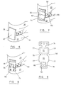
- an elastomeric rubber block such as silastic, is encapsulated and held in compression by a textile fabric 2.
- the elastomeric block may be a silicone rubber, for instance with a Shore A scale hardness of 35-80°.
- the fabric used in the invention may be formed by flat or circular weaving, knitting, braiding or preferably embroidery.
- a wide variety of fibre materials are applicable to the fabric, including, polyester, polypropylene, polyethylene, carbon fibre, glass, glass fibre, polyaramide, metal, copolymers, polylactic acid, polyglycolic acid, biodegradable fibres, silk, cellulosic and polycaprolactone fibres.
- the structure of the fabric is selected such that fibrous tissue may penetrate between the fibres or threads forming the fabric. Tissue ingrowth is highly desirable and may even be possible to an extent where in growth replaces one or more components of the prosthesis. Biodegradation of the prosthesis may be encouraged in such cases, for instance giving rise to replacement of the fabric and/or even disc regrowth.
- the cross section has been modified to match that of the natural cervical disc with the upper surface 4 of the disc 6 having a larger surface area than the lower surface 8 of the disc.
- the textile fabric 2 conforms to the profile of the disc 6.
- the core for the prosthesis is provided in a variety of sizes.
- Figure 3b illustrates the maximum cross section of the core, normally taken parallel to front face 10, and generally the cross section extending between one rear face 12 to side 14 junction and the other rear face 12 to side 14 junction.
- the cross section illustrates the maximum upper width, uw, and the maximum lower width, lw.
- the Figure 3c illustration displays the minimum width cross section, generally provided at or in proximity to the front face 10. This Figure illustrates the minimal upper width, un, and the lower minimal width, ln.
- Figure 3d illustrates, from the side, the variation in thickness of the core between the front face 10 and the rear face 12.
- the maximum thickness, mt is generally provided at or in proximity to the rear face 12, with the lowest thickness, It, generally being provided at or in proximity to the front face 10.
- the corners of the core are generally rounded, as illustrated.
- Typical sizes for the dimensions described above may be provided according to the following table.
- Sets of prostheses of different sizes may be offered for a particular disc in the spine.
- the correct size may be evaluated by inserting into the vacant disc space metal sizers each provided on a rod, and of each corresponding in its dimensions to the profile of a prosthesis.
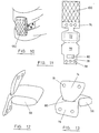
- Figure 4 is a perspective view rom the front of a spine of two adjacent vertebral bodies 20, 22 with the prosthetic disc 24 in the disc space 26 between them.
- Prosthesis of the type provided in the present invention are inserted following a disectomy. This involves removing the portion of the anterior longitudinal ligament spanning the vertebral space in question, removing the disc (both annulus and nucleus pulposis) and inserting into the vacant disc space the prosthesis. Where applicable, the prosthesis is then anchored in place, as described in more detail below.
- the front edge of the solid core is positioned level with, or more preferably recessed relative to the front edge of the vertebrae, for instance by 2 to 4mm.
- This technique is surgically attractive in that the preparation of the disc space, to receive the disc prosthesis, involves steps already established for standard disc removal surgery. The surgeon is thus not required to change techniques.
- the construction 28 is anchored to the vertebral bodies 20, 22 on either side of the disc space 26 using fixation devices 32 imbedded into the vertebrae and defining the apex of each element of the cradle.
- the cradle 28 may be formed by passing the elements of the cradle, such as a suture around the head of a screw secured to the vertebral body to define the apex of each cradle element.
- This construction 28 may be formed of either single or multiple yarns, sutures, braids or other flexible textile elements which are formed into a loop either before or during the operation.
- the cradle 28 acts to secure the prosthetic disc 24 within the disc space 26 while the spine is being flexed, extended or rotated.
- the cradle 28 also acts to support the motion segment of the spine by providing textile fibres that match the orientation of the fibres within the natural annulus, which is the fibrous structure across the front of the disc space.
- the construct or cradle 28 may be added to any of the applications shown in Figures 6 to 9.
- FIG. 6 shows the cradle replaced with a preformed fabric element 40, which may have fibres arranged within it which match the orientation of the cradle structure detailed above.
- This fabric element 40 may be either a separate element positioned across the front of the disc space 26 after the insertion of the prosthetic disc 24, as shown, or it may be attached to the disc 24.
- the element 40 may be secured to the vertebral bodies 20, 22 on either side of the disc space 26 by sutures passing to bone anchors (not shown) implanted into the vertebrae.
- the fabric element 40 may be secured using bone screws (not shown) passing either directly through the fabric element 40 or inserted through fixation holes in the fabric, with or without the use of a reinforcing element, such as a washer or rivet.
- the fabric element 40 may be secured by a pair of metal plates (not shown), one of which is fastened to each vertebral body 20, 22 over the fabric element 40.
- the fabric forming the flanges 52, 54, each for attachment to a vertebral body 20, 22, is a continuation of the encapsulating fabric 56.
- the elastomeric block within the fabric 56 is held in position by the upper 52 and lower 54 fabric elements being fastened to each other in a line 62 along the front edge of the prosthetic disc.
- Figure 8 shows a preferred version of the invention in its position of use.
- Figure 9 illustrates the plan profile of the textile element of the construction shown in Figure 8 before the sides of the encapsulating element have been fastened together.
- the view shows the inside surfaces of the lower face 70 and upper face 72 of the encapsulating fabric, the faces 70, 72 facing one another in the assembled form, the core being provided between these two faces.
- the continuations 74, 76 of the encapsulating fabric 56 form an interdigitation in the assembled state.
- faces 70, 72 are sewn together along edges 77 to form a pocket sealed at the edges 77 by the stitches and at the back by the junction 79 of the two faces 70, 72.
- the continuation 74 of the upper fabric 72 is passed through a hole 80 in the continuation of the lower fabric 76 and is attached to the lower vertebral body 22.
- the continuation 76 of the lower fabric crosses over to its fixation site on the upper vertebral body 20 as a result.
- the flange 76 attached to the upper vertebral body 20 is secured using bone screws (not shown) received in apertures 78 in the flange 76 and the flange 74 attached to the lower vertebral body 22 is attached using sutures 82 which are in turn attached to bone anchors (not shown) imbedded in the vertebral body.
- the visco-elastic properties of the prosthetic disc are an ideal match of the visco-elastic properties of the natural disc when the encapsulated textile / elastomeric inserts are subjected to compression / relaxation with the constructs illustrated in Figures 8 and 9. Flexion of the spine will impose a direct compressive load on the prosthetic disc and extension of the spine will create tension in the flanges 74, 76 which will by virtue of the interdigitation impose a compressive load on the prosthetic disc.
- the prosthesis in effect mimics a natural disc to a large extent.
- the deformable core, insert or block performs a very similar function to the nucleus pulposis.
- the fabric encapsulation performs a very similar function to the annulus.
- the flanges perform a very similar function to the anterior longitundinal ligament extending down the front of the spine.
- the pattern of Figure 9 may be cut out of a preformed fabric but it is preferably formed using embroidery which can optimally position the fibres within the fabric to maximise the load bearing potential of the construction.
- FIGS 12 and 13 are further illustrations of the embodiment of the invention illustrated in Figures 8 and 9.
- the prosthesis comprises a fabric sheath for an internal core of resilient but suitably deformable material.
- Flanges 74, 76 extend from the sheath 56 and are interdigitated, in the manner outlined above, by passing the flange 74 through the aperture 80 in the flange 76.
- the flanges 74, 76 each taper outward from a reduced width where they interdigitate to an increased width towards the anchor receiving apertures 78.
- the type of construction shown in Figure 8 has an additional fabric element 100 added over the front of the device, in a manner similar to that shown in Figure 6.
- This element 100 may be either a continuation of the upper 76 or, as shown, lower 74 flange, or a separate fabric element.
- the additional fabric element 100 acts to increase the torsional resistance of the construction. It limits the compression of the silicon insert resulting from the tension in the flanges when the spine is placed in extension and it also is a barrier to prevent the backing-out of bone screws used to secure the flanges to the vertebral bodies 20, 22.
- Figure 11 shows a similar plan view to that shown in Figure 9 but with the addition of the fabric 100 to be attached over the front of the construction when in situ.
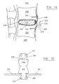
- the prosthesis 210 replaces the natural disc between vertebrae 200 and 202.
- the prosthesis 210 is provided according to the form illustrated in Figures 10 and 11 and comprises a visco-elastic block, insert or core 212, of greater thickness near the insertion side 214 than away from the insertion side 214. This conforms to the natural shape of the space between the vertebrae 200 and 202.
- the insert 212 is encased in the fabric 216 in the manner described above.
- the flanges 218 and 220 extending from the disc space are interdigitated at location 222 and fixed by bone anchors 224.
- the prosthesis is provided with a fabric pad 226 between the interdigitation location 222 and the core 212. This promotes the correct positioning of the core 212 relative to the vertebrae and the overall prosthesis when the spine is in both flexion and extension. By providing the pad 226 this extension of the spine tends to pull the flanges 218, 220 apart and so squeeze the pad 226 towards the interior of the disc space holding the insert 212 in position.
- the pad 226 holds the insert 212 away from the front of the disc space where the compression force exerted by the vertebrae 200 and 202 is greatest.
- the pad 226 may be provided as a distinct element, as shown, which is introduced during assembly, or more preferably, the type of construction illustrated in Figures 15, 16 and 17 may be provided.
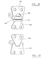
- Figure 15 represents in plan view the fabric component prior to assembly. Faces 300 and 302 face one another and contact the core in use. Flange 304 is provided with an aperture 306 through which the opposing flange 308 is interdigitated in use. Apertures 310 are provided in the flanges 304, 308 to accommodate the anchors.
- This embodiment of the invention also includes laterally extending arm portions 312 made of the fabric material. These arm portions are folded into multiple folds, in use, to provide the cushion pad between the interdigitation location and the core.
- Figure 16 illustrates the fabric encapsulation of Figure 15 in its assembled state prior to the insertion of the core.
- the arms 312 are folded in on one another to provide a cushion mounted on the lower flange 308.
- the core not shown, is inserted into the internal space 320.
- the lower flange 308 is passed up through the aperture 306 in the upper flange 304. This pushes the folded pad 312 across the aperture leading to the core and provides a cushion for the core.
- the structure resumes tne format illustrated in Figure 17.
- the pad 312 provides the benefits outlined above in relation to Figure 14 by promoting retention of the core within the disc space.
- the pad provides complete encapsulation of the core and also ensures that the edge of the core is held back from the front edge of the disc space. This hold back is beneficial in ensuring that no block to the full flexion of the vertebrae adjacent to the disc space. The risk of the front edge of the prosthesis being nipped by the front edge of the disc is also reduced.
- the prosthesis structures provided according to the present invention enable a more natural movement to be provided in spines where disc damage would normally necessitate fusion and no mobility at that location or the provision of a vacant disc space and hypermobility at that location.
- the prosthesis is closely matched to a natural disc in terms of disc height, stiffness in compression and three planes of rotation, viscoelastic behaviour and the transmission of physiological stress to adjacent vertebrae.
- Prostheses of the present invention are also beneficial over those used in the prior art in terms of their ease of positioning, tolerance in positioning and in terms of the physiological nature and extent of the movement provided. Behaviour more closely replicating natural discs is provided.
- the structure of the prosthesis provides suitable constraints to excessive movement.
- Figure 18 illustrates the hysteresis loop for sagittal rotation of a C4/C5 joint with a natural disc, plot A, (the arrows indicate the direction of flexure, left to right for forward, right to left for back) and for a disc according to the present invention, plot B.
- plot A the arrows indicate the direction of flexure, left to right for forward, right to left for back
- plot B the arrows indicate the direction of flexure, left to right for forward, right to left for back
- plot B the plots very closely match one another reflecting the near equivalence of the prosthesis to the natural disc during such movement. The deviation between the plots is within the variation arising between two natural discs.
- Figure 19 shows a similar set of hysteresis plots for a natural disc, plot A, and a prosthesis according to the invention, plot B, during a lateral rotation test, again illustrating the near equivalence in performance.
- Multi-segment evaluation of the prosthesis also indicated that the position of the centre of rotation was very similar when a prosthesis according to the present invention was deployed, when compared with a fully natural disc multi-segment test.
- the present invention merely needs the fabric to be cut to an extent enabling the core to be removed.
- the fabric flanges can be left in-situ, avoiding problems where, for instance, significant tissue in-growth has occurred. Tissue in-growth on the flanges may be avoided by providing an in-growth retarding coating to these parts.
Landscapes
- Health & Medical Sciences (AREA)
- Engineering & Computer Science (AREA)
- Biomedical Technology (AREA)
- Orthopedic Medicine & Surgery (AREA)
- Neurology (AREA)
- Heart & Thoracic Surgery (AREA)
- Oral & Maxillofacial Surgery (AREA)
- Transplantation (AREA)
- Cardiology (AREA)
- Vascular Medicine (AREA)
- Life Sciences & Earth Sciences (AREA)
- Animal Behavior & Ethology (AREA)
- General Health & Medical Sciences (AREA)
- Public Health (AREA)
- Veterinary Medicine (AREA)
- Prostheses (AREA)
- Materials For Medical Uses (AREA)
Abstract
Description

Claims (25)
- A disc prosthesis (24) comprising a block (6) of an elastomeric or visco-elastic material which is encapsulated by a textile fabric (2) characterised in that a flange (40; 52, 54; 74, 76), suitable for attachment to vertebral bodies (20, 22), is provided as a continuation of the encapsulating fabric (2).
- A disc prosthesis (24) comprising a block (6) of an elastomeric or visco-elastic material (24) which is encapsulated by a textile fabric (2), characterised in that the textile fabric (2) defines a pocket which receives the block (6), the fabric (2) being provided with one or more further portions (40; 52, 54; 74, 76) to provide closure for the pocket receiving the block (6), the first and second further portions (40; 52, 54; 74, 76) extending from the fabric to form flanges of fabric, the flanges being attached to the vertebrae (20, 22) adjacent to the prosthesis (24) in use.
- A prosthesis according to claim 1 or claim 2 in which one of the flanges (76) is provided with an aperture (80).
- A prosthesis according to claim 3 in which the other flange (74) is provided with a reduced dimension neck.
- A prosthesis according to any preceding claim in which a flange or continuation of the fabric (76) is interdigitated with another flange or continuation (74) of the fabric by passing through an aperture (80) in the continuation of the fabric.
- A prosthesis according to any preceding claim in which the block (6) of an elastomeric or visco-elastic material is held under compression by the encapsulating textile fabric (2).
- A prosthesis according to any preceding claim in which the fabric (2) is formed using weaving, knitting, braiding or embroidery.
- A prosthesis according to any preceding claim in which the block (6) is encapsulated by inserting the block (6) into a textile receptacle formed by folding the fabric (2) on to itself and stitching or sealing closed the free edges (70, 72).
- A prosthesis according to any preceding claim in which the upper surface (4) of the block (6) has a larger surface area than the lower surface (8) of the block (6).
- A prosthesis according to any preceding claim in which an additional fabric element (40) over the front of the prosthesis is provided.
- A prosthesis according to any preceding claim in which the maximum width of the upper surface (4) is greater than the maximum width of the lower surface (8).
- A prosthesis according to any preceding claim in which the minimum width of the upper surface (4) is greater than the minimum width of the lower surface (8) of the block (6).
- A prosthesis according to any preceding claim in which the front thickness (mt) of the block (6) is greater than the back thickness (It) of the block (6), the front being the portion of the block (6) nearer the front of the spine in use.
- A prosthesis according to any preceding claim in which the block (6) is wider towards the front face (12) than towards the rear face (10).
- A prosthesis according to any preceding claim in which the maximum length (1) from the front face (12) of the block (6) to the rear face (10) of the block (6) is between 10 and 15mm.
- A prosthesis according to any preceding claim in which the maximum width (uw) of the upper surface (4) of the block (6) is between 12.5 and 16.5mm.
- A prosthesis according to any preceding claim in which the minimum lower width (In) of the block (6) is between 8.5 and 12.5mm.
- A prosthesis according to any preceding claim in which the maximum thickness (mt) of the block (6) is between 2.5 and 5.5mm.
- A prosthesis according to any preceding claim in which the block (6) provides planar upper (4) and lower (8) surfaces, the upper surface (4) having a greater width than the lower surface (8), the block (6) having a greater thickness towards the front face (12) than towards the rear face (10).
- A prosthesis according to any preceding claim in which the fabric (2) is formed from a piece of fabric having a first portion (70) and a second portion (72), the first and second portions (70, 72) being joined by an integral part of the fabric, the first and second portions being provided in opposition to one another, the edges (77) of the first and second portions (70, 72) being stitched to one another to provide an encapsulating portion of the fabric (2) for the block (6).
- A prosthesis according to any preceding claim in which the fabric (2) is provided with one or more further portions (100), the one or more further portions (100) being attached to one or both of the first and second portions (70, 72), the one or more further portions (100) providing closure for a pocket receiving the block.
- A prosthesis according to any preceding claim in which the one or more further portions provide a first further portion (74) and a second further portion (76), in which one of the first or second further portions is provided with an aperture (80), and the first and second further portions (74, 76)are interdigitated by passing the other of the first or second further portions (74, 76) through the aperture (80) in the said one of the first or second further portions (74, 76).
- A prosthesis according to claim 22 in which the first and second portions form a pocket receiving the block (212), a portion of one of the further portions (216) passing through an aperture or gap in one of the other further portions (218), thereby forming a closure for the pocket receiving the block (212), a pad (226) being provided within the pocket between the block (212) and a closure for the pocket receiving the block (212).
- A prosthesis according to claim 23 in which the pad (226) is formed of the retaining fabric material and is integral with the retaining fabric material.
- A prosthesis according to claim 23 in which the pad block is formed by folding a portion (312) of the retaining fabric material.
Applications Claiming Priority (3)
| Application Number | Priority Date | Filing Date | Title |
|---|---|---|---|
| GB9713330 | 1997-06-25 | ||
| GBGB9713330.0A GB9713330D0 (en) | 1997-06-25 | 1997-06-25 | Surgical implant |
| PCT/GB1998/001707 WO1999000074A1 (en) | 1997-06-25 | 1998-06-25 | Surgical implant |
Publications (2)
| Publication Number | Publication Date |
|---|---|
| EP0991379A1 EP0991379A1 (en) | 2000-04-12 |
| EP0991379B1 true EP0991379B1 (en) | 2005-01-12 |
Family
ID=10814859
Family Applications (1)
| Application Number | Title | Priority Date | Filing Date |
|---|---|---|---|
| EP98930866A Expired - Lifetime EP0991379B1 (en) | 1997-06-25 | 1998-06-25 | Surgical implant |
Country Status (11)
| Country | Link |
|---|---|
| US (1) | US6093205A (en) |
| EP (1) | EP0991379B1 (en) |
| JP (2) | JP4361141B2 (en) |
| KR (1) | KR20010020519A (en) |
| AT (1) | ATE286697T1 (en) |
| AU (1) | AU743650B2 (en) |
| DE (1) | DE69828605T2 (en) |
| ES (1) | ES2236914T3 (en) |
| GB (1) | GB9713330D0 (en) |
| WO (1) | WO1999000074A1 (en) |
| ZA (1) | ZA985547B (en) |
Families Citing this family (320)
| Publication number | Priority date | Publication date | Assignee | Title |
|---|---|---|---|---|
| US7520890B2 (en) * | 1998-01-26 | 2009-04-21 | Phillips Peter W | Reinforced graft and method of deployment |
| EP1100381B1 (en) | 1998-08-03 | 2005-08-31 | Anson Medical Limited | Devices for the repair of arteries |
| FR2787017B1 (en) * | 1998-12-11 | 2001-04-27 | Dimso Sa | INTERVERTEBRAL DISC PROSTHESIS WITH IMPROVED MECHANICAL BEHAVIOR |
| US20070038231A1 (en) | 1999-05-28 | 2007-02-15 | Ferree Bret A | Methods and apparatus for treating disc herniation and preventing the extrusion of interbody bone graft |
| US7273497B2 (en) | 1999-05-28 | 2007-09-25 | Anova Corp. | Methods for treating a defect in the annulus fibrosis |
| US20060247665A1 (en) * | 1999-05-28 | 2006-11-02 | Ferree Bret A | Methods and apparatus for treating disc herniation and preventing the extrusion of interbody bone graft |
| US6520996B1 (en) * | 1999-06-04 | 2003-02-18 | Depuy Acromed, Incorporated | Orthopedic implant |
| FR2897259B1 (en) | 2006-02-15 | 2008-05-09 | Ldr Medical Soc Par Actions Si | INTERSOMATIC TRANSFORAMINAL CAGE WITH INTERBREBAL FUSION GRAFT AND CAGE IMPLANTATION INSTRUMENT |
| WO2004100841A1 (en) | 1999-08-18 | 2004-11-25 | Intrinsic Therapeutics, Inc. | Devices and method for augmenting a vertebral disc nucleus |
| US7998213B2 (en) | 1999-08-18 | 2011-08-16 | Intrinsic Therapeutics, Inc. | Intervertebral disc herniation repair |
| WO2002054978A2 (en) * | 1999-08-18 | 2002-07-18 | Intrinsic Orthopedics Inc | Devices and method for nucleus pulposus augmentation and retention |
| US6883520B2 (en) * | 1999-08-18 | 2005-04-26 | Intrinsic Therapeutics, Inc. | Methods and apparatus for dynamically stable spinal implant |
| US8323341B2 (en) | 2007-09-07 | 2012-12-04 | Intrinsic Therapeutics, Inc. | Impaction grafting for vertebral fusion |
| US7972337B2 (en) | 2005-12-28 | 2011-07-05 | Intrinsic Therapeutics, Inc. | Devices and methods for bone anchoring |
| US7717961B2 (en) * | 1999-08-18 | 2010-05-18 | Intrinsic Therapeutics, Inc. | Apparatus delivery in an intervertebral disc |
| US6783546B2 (en) | 1999-09-13 | 2004-08-31 | Keraplast Technologies, Ltd. | Implantable prosthetic or tissue expanding device |
| US6371984B1 (en) * | 1999-09-13 | 2002-04-16 | Keraplast Technologies, Ltd. | Implantable prosthetic or tissue expanding device |
| US6964674B1 (en) * | 1999-09-20 | 2005-11-15 | Nuvasive, Inc. | Annulotomy closure device |
| US7052516B2 (en) | 1999-10-20 | 2006-05-30 | Anulex Technologies, Inc. | Spinal disc annulus reconstruction method and deformable spinal disc annulus stent |
| US20030153976A1 (en) | 1999-10-20 | 2003-08-14 | Cauthen Joseph C. | Spinal disc annulus reconstruction method and spinal disc annulus stent |
| US7951201B2 (en) | 1999-10-20 | 2011-05-31 | Anulex Technologies, Inc. | Method and apparatus for the treatment of the intervertebral disc annulus |
| US8128698B2 (en) | 1999-10-20 | 2012-03-06 | Anulex Technologies, Inc. | Method and apparatus for the treatment of the intervertebral disc annulus |
| US7004970B2 (en) | 1999-10-20 | 2006-02-28 | Anulex Technologies, Inc. | Methods and devices for spinal disc annulus reconstruction and repair |
| US8632590B2 (en) | 1999-10-20 | 2014-01-21 | Anulex Technologies, Inc. | Apparatus and methods for the treatment of the intervertebral disc |
| US7615076B2 (en) | 1999-10-20 | 2009-11-10 | Anulex Technologies, Inc. | Method and apparatus for the treatment of the intervertebral disc annulus |
| US7935147B2 (en) | 1999-10-20 | 2011-05-03 | Anulex Technologies, Inc. | Method and apparatus for enhanced delivery of treatment device to the intervertebral disc annulus |
| US6592625B2 (en) | 1999-10-20 | 2003-07-15 | Anulex Technologies, Inc. | Spinal disc annulus reconstruction method and spinal disc annulus stent |
| US6592624B1 (en) | 1999-11-24 | 2003-07-15 | Depuy Acromed, Inc. | Prosthetic implant element |
| US6432106B1 (en) * | 1999-11-24 | 2002-08-13 | Depuy Acromed, Inc. | Anterior lumbar interbody fusion cage with locking plate |
| GB2359024A (en) * | 2000-02-09 | 2001-08-15 | Anson Medical Ltd | Fixator for arteries |
| US7717958B2 (en) * | 2000-02-16 | 2010-05-18 | Trans1, Inc. | Prosthetic nucleus apparatus |
| US6899716B2 (en) * | 2000-02-16 | 2005-05-31 | Trans1, Inc. | Method and apparatus for spinal augmentation |
| US7744599B2 (en) | 2000-02-16 | 2010-06-29 | Trans1 Inc. | Articulating spinal implant |
| WO2004049915A2 (en) | 2000-02-16 | 2004-06-17 | Trans1 Inc. | Method and apparatus for spinal distraction and fusion |
| US7776068B2 (en) * | 2003-10-23 | 2010-08-17 | Trans1 Inc. | Spinal motion preservation assemblies |
| US7938836B2 (en) * | 2003-10-23 | 2011-05-10 | Trans1, Inc. | Driver assembly for simultaneous axial delivery of spinal implants |
| US7014633B2 (en) * | 2000-02-16 | 2006-03-21 | Trans1, Inc. | Methods of performing procedures in the spine |
| US7601171B2 (en) * | 2003-10-23 | 2009-10-13 | Trans1 Inc. | Spinal motion preservation assemblies |
| US6558390B2 (en) | 2000-02-16 | 2003-05-06 | Axiamed, Inc. | Methods and apparatus for performing therapeutic procedures in the spine |
| US6740093B2 (en) | 2000-02-28 | 2004-05-25 | Stephen Hochschuler | Method and apparatus for treating a vertebral body |
| US6805695B2 (en) | 2000-04-04 | 2004-10-19 | Spinalabs, Llc | Devices and methods for annular repair of intervertebral discs |
| FR2808995B1 (en) | 2000-05-18 | 2003-02-21 | Aesculap Sa | INTERSOMATIC CAGE WITH UNIFIED GRAFT |
| US7008427B2 (en) | 2000-05-25 | 2006-03-07 | Orthoplex, Llc | Inter-vertebral disc prosthesis for rachis through anterior surgery thereof |
| USD493225S1 (en) | 2000-06-12 | 2004-07-20 | Ortho Development Corporation | Implant |
| US6579318B2 (en) * | 2000-06-12 | 2003-06-17 | Ortho Development Corporation | Intervertebral spacer |
| WO2002003885A2 (en) * | 2000-07-10 | 2002-01-17 | Michelson Gary K | Flanged interbody spinal fusion implants |
| US7114501B2 (en) * | 2000-08-14 | 2006-10-03 | Spine Wave, Inc. | Transverse cavity device and method |
| US7204851B2 (en) * | 2000-08-30 | 2007-04-17 | Sdgi Holdings, Inc. | Method and apparatus for delivering an intervertebral disc implant |
| US20050154463A1 (en) * | 2000-08-30 | 2005-07-14 | Trieu Hal H. | Spinal nucleus replacement implants and methods |
| US7503936B2 (en) * | 2000-08-30 | 2009-03-17 | Warsaw Orthopedic, Inc. | Methods for forming and retaining intervertebral disc implants |
| US6620196B1 (en) | 2000-08-30 | 2003-09-16 | Sdgi Holdings, Inc. | Intervertebral disc nucleus implants and methods |
| US20020026244A1 (en) * | 2000-08-30 | 2002-02-28 | Trieu Hai H. | Intervertebral disc nucleus implants and methods |
| US6572654B1 (en) | 2000-10-04 | 2003-06-03 | Albert N. Santilli | Intervertebral spacer |
| US6733531B1 (en) * | 2000-10-20 | 2004-05-11 | Sdgi Holdings, Inc. | Anchoring devices and implants for intervertebral disc augmentation |
| US6613089B1 (en) * | 2000-10-25 | 2003-09-02 | Sdgi Holdings, Inc. | Laterally expanding intervertebral fusion device |
| JP2004515311A (en) | 2000-10-25 | 2004-05-27 | エスディージーアイ・ホールディングス・インコーポレーテッド | Vertically expanding intervertebral fusion device |
| JP4130126B2 (en) * | 2000-10-27 | 2008-08-06 | ウォーソー・オーソペディック・インコーポレーテッド | Annulus repair system and method |
| US6579319B2 (en) | 2000-11-29 | 2003-06-17 | Medicinelodge, Inc. | Facet joint replacement |
| US20050080486A1 (en) * | 2000-11-29 | 2005-04-14 | Fallin T. Wade | Facet joint replacement |
| SE525131C2 (en) * | 2001-01-15 | 2004-12-07 | Artimplant Ab | Implants for reconstruction of joints |
| US6576017B2 (en) * | 2001-02-06 | 2003-06-10 | Sdgi Holdings, Inc. | Spinal implant with attached ligament and methods |
| US6562073B2 (en) | 2001-02-06 | 2003-05-13 | Sdgi Holding, Inc. | Spinal bone implant |
| US6645211B2 (en) * | 2001-02-07 | 2003-11-11 | Howmedica Osteonics Corp. | Orthopedic support system and method of installation |
| US6673113B2 (en) | 2001-10-18 | 2004-01-06 | Spinecore, Inc. | Intervertebral spacer device having arch shaped spring elements |
| US7169182B2 (en) * | 2001-07-16 | 2007-01-30 | Spinecore, Inc. | Implanting an artificial intervertebral disc |
| US6673075B2 (en) | 2001-02-23 | 2004-01-06 | Albert N. Santilli | Porous intervertebral spacer |
| US7229441B2 (en) * | 2001-02-28 | 2007-06-12 | Warsaw Orthopedic, Inc. | Flexible systems for spinal stabilization and fixation |
| US6827743B2 (en) * | 2001-02-28 | 2004-12-07 | Sdgi Holdings, Inc. | Woven orthopedic implants |
| US6652585B2 (en) | 2001-02-28 | 2003-11-25 | Sdgi Holdings, Inc. | Flexible spine stabilization system |
| US7090698B2 (en) | 2001-03-02 | 2006-08-15 | Facet Solutions | Method and apparatus for spine joint replacement |
| US7344539B2 (en) | 2001-03-30 | 2008-03-18 | Depuy Acromed, Inc. | Intervertebral connection system |
| FR2824261B1 (en) | 2001-05-04 | 2004-05-28 | Ldr Medical | INTERVERTEBRAL DISC PROSTHESIS AND IMPLEMENTATION METHOD AND TOOLS |
| US6736848B2 (en) | 2001-05-29 | 2004-05-18 | Sdgi Holdings, Inc. | Method and apparatus for using formable polymers for orthopedic support |
| US20090234457A1 (en) * | 2001-06-29 | 2009-09-17 | The Regents Of The University Of California | Systems, devices and methods for treatment of intervertebral disorders |
| AU2002318159A1 (en) | 2001-06-29 | 2003-03-03 | The Regents Of The University Of California | Biodegradable/bioactive nucleus pulposus implant and method for treating degenerated intervertebral discs |
| FR2827156B1 (en) * | 2001-07-13 | 2003-11-14 | Ldr Medical | VERTEBRAL CAGE DEVICE WITH MODULAR FASTENING |
| US20030055503A1 (en) * | 2001-09-19 | 2003-03-20 | O'neil Michael J. | Alignment verification device and method of use |
| US7713302B2 (en) | 2001-10-01 | 2010-05-11 | Spinecore, Inc. | Intervertebral spacer device utilizing a spirally slotted belleville washer having radially spaced concentric grooves |
| US7771477B2 (en) | 2001-10-01 | 2010-08-10 | Spinecore, Inc. | Intervertebral spacer device utilizing a belleville washer having radially spaced concentric grooves |
| US20060142765A9 (en) * | 2001-10-15 | 2006-06-29 | Dixon Robert A | Vertebral implant for bone fixation or interbody use |
| US20060129242A1 (en) * | 2001-12-28 | 2006-06-15 | Brian Bergeron | Pseudo arthrosis device |
| US6736850B2 (en) * | 2001-12-28 | 2004-05-18 | Spinal Concepts, Inc. | Vertebral pseudo arthrosis device and method |
| EP1487363A1 (en) * | 2002-02-25 | 2004-12-22 | Dzung H. Dinh | Methods and apparatuses for promoting fusion of vertebrae |
| US6682563B2 (en) | 2002-03-04 | 2004-01-27 | Michael S. Scharf | Spinal fixation device |
| FR2837094B1 (en) * | 2002-03-15 | 2004-11-26 | Fixano | INTERVERTEBRAL IMPLANT |
| US20080027548A9 (en) | 2002-04-12 | 2008-01-31 | Ferree Bret A | Spacerless artificial disc replacements |
| US8038713B2 (en) | 2002-04-23 | 2011-10-18 | Spinecore, Inc. | Two-component artificial disc replacements |
| US6706068B2 (en) | 2002-04-23 | 2004-03-16 | Bret A. Ferree | Artificial disc replacements with natural kinematics |
| US20060004454A1 (en) * | 2002-04-24 | 2006-01-05 | Ferree Bret A | Assembled disc spacers |
| US20040030391A1 (en) * | 2002-04-24 | 2004-02-12 | Bret Ferree | Artificial intervertebral disc spacers |
| US7179294B2 (en) | 2002-04-25 | 2007-02-20 | Warsaw Orthopedic, Inc. | Articular disc prosthesis and method for implanting the same |
| US7338525B2 (en) * | 2002-04-30 | 2008-03-04 | Ferree Bret A | Methods and apparatus for preventing the migration of intradiscal devices |
| US8388684B2 (en) | 2002-05-23 | 2013-03-05 | Pioneer Signal Technology, Inc. | Artificial disc device |
| US7001433B2 (en) * | 2002-05-23 | 2006-02-21 | Pioneer Laboratories, Inc. | Artificial intervertebral disc device |
| US20040049283A1 (en) * | 2002-06-04 | 2004-03-11 | Tushar Patel | Medical implant and method of reducing back pain |
| EP1542626B1 (en) * | 2002-08-15 | 2012-09-26 | Synthes GmbH | Controlled artificial intervertebral disc implant |
| DE10247762A1 (en) * | 2002-10-14 | 2004-04-22 | Waldemar Link (Gmbh & Co.) | Intervertebral prosthesis |
| US7273496B2 (en) * | 2002-10-29 | 2007-09-25 | St. Francis Medical Technologies, Inc. | Artificial vertebral disk replacement implant with crossbar spacer and method |
| US7083649B2 (en) * | 2002-10-29 | 2006-08-01 | St. Francis Medical Technologies, Inc. | Artificial vertebral disk replacement implant with translating pivot point |
| US7682392B2 (en) | 2002-10-30 | 2010-03-23 | Depuy Spine, Inc. | Regenerative implants for stabilizing the spine and devices for attachment of said implants |
| US20040133278A1 (en) * | 2002-10-31 | 2004-07-08 | Marino James F. | Spinal disc implant |
| FR2846550B1 (en) | 2002-11-05 | 2006-01-13 | Ldr Medical | INTERVERTEBRAL DISC PROSTHESIS |
| US7776042B2 (en) * | 2002-12-03 | 2010-08-17 | Trans1 Inc. | Methods and apparatus for provision of therapy to adjacent motion segments |
| US6974479B2 (en) * | 2002-12-10 | 2005-12-13 | Sdgi Holdings, Inc. | System and method for blocking and/or retaining a prosthetic spinal implant |
| US20040210310A1 (en) * | 2002-12-10 | 2004-10-21 | Trieu Hai H. | Implant system and method for intervertebral disc augmentation |
| US20040158254A1 (en) | 2003-02-12 | 2004-08-12 | Sdgi Holdings, Inc. | Instrument and method for milling a path into bone |
| FR2851158A1 (en) * | 2003-02-14 | 2004-08-20 | Alain Ventimiglia | Inter-vertebral prosthesis for replacing inter-vertebral disc, has two elastic plates, each including perpendicular extension to fix plate to vertebral, and two stainless steel plates to push extensions to vertebra |
| US6908484B2 (en) | 2003-03-06 | 2005-06-21 | Spinecore, Inc. | Cervical disc replacement |
| EP1635744A4 (en) * | 2003-03-06 | 2013-03-13 | Spinecore Inc | Instrumentation and methods for use in implanting a cervical disc replacement device |
| US7918876B2 (en) | 2003-03-24 | 2011-04-05 | Theken Spine, Llc | Spinal implant adjustment device |
| US7112222B2 (en) * | 2003-03-31 | 2006-09-26 | Depuy Spine, Inc. | Anterior lumbar interbody fusion cage with locking plate |
| US7819903B2 (en) * | 2003-03-31 | 2010-10-26 | Depuy Spine, Inc. | Spinal fixation plate |
| US7377930B2 (en) * | 2003-04-02 | 2008-05-27 | Frank Loughran | Nerve protecting tube |
| WO2004089240A2 (en) | 2003-04-04 | 2004-10-21 | Theken Disc, Llc | Artificial disc prosthesis |
| US7326200B2 (en) * | 2003-07-25 | 2008-02-05 | Warsaw Orthopedic, Inc. | Annulus repair systems, instruments and techniques |
| US7909869B2 (en) | 2003-08-05 | 2011-03-22 | Flexuspine, Inc. | Artificial spinal unit assemblies |
| US20060229729A1 (en) * | 2003-08-05 | 2006-10-12 | Gordon Charles R | Expandable intervertebral implant for use with instrument |
| US7799082B2 (en) | 2003-08-05 | 2010-09-21 | Flexuspine, Inc. | Artificial functional spinal unit system and method for use |
| US7753958B2 (en) | 2003-08-05 | 2010-07-13 | Gordon Charles R | Expandable intervertebral implant |
| DE10340150A1 (en) * | 2003-08-26 | 2005-03-31 | Aesculap Ag & Co. Kg | Implant for closing an opening of the annulus fibrosus |
| US20050055099A1 (en) * | 2003-09-09 | 2005-03-10 | Ku David N. | Flexible spinal disc |
| US7530993B2 (en) | 2003-10-23 | 2009-05-12 | Trans1 Inc. | Method of spinal fixation |
| US7670377B2 (en) | 2003-11-21 | 2010-03-02 | Kyphon Sarl | Laterally insertable artifical vertebral disk replacement implant with curved spacer |
| US7481839B2 (en) * | 2003-12-02 | 2009-01-27 | Kyphon Sarl | Bioresorbable interspinous process implant for use with intervertebral disk remediation or replacement implants and procedures |
| US20050125066A1 (en) | 2003-12-08 | 2005-06-09 | Innovative Spinal Technologies | Nucleus replacement securing device and method |
| US7217291B2 (en) | 2003-12-08 | 2007-05-15 | St. Francis Medical Technologies, Inc. | System and method for replacing degenerated spinal disks |
| US7753937B2 (en) | 2003-12-10 | 2010-07-13 | Facet Solutions Inc. | Linked bilateral spinal facet implants and methods of use |
| US20050165484A1 (en) * | 2004-01-22 | 2005-07-28 | Ferree Bret A. | Artificial disc replacement (ADR) fixation methods and apparatus |
| RU2354334C2 (en) | 2004-02-04 | 2009-05-10 | Лдр Медикаль | Intervertebral disc prosthesis |
| FR2865629B1 (en) | 2004-02-04 | 2007-01-26 | Ldr Medical | INTERVERTEBRAL DISC PROSTHESIS |
| WO2005077304A1 (en) | 2004-02-06 | 2005-08-25 | Georgia Tech Research Corporation | Load bearing biocompatible device |
| WO2005077013A2 (en) | 2004-02-06 | 2005-08-25 | Georgia Tech Research Corporation | Surface directed cellular attachment |
| US7993373B2 (en) | 2005-02-22 | 2011-08-09 | Hoy Robert W | Polyaxial orthopedic fastening apparatus |
| US8562649B2 (en) | 2004-02-17 | 2013-10-22 | Gmedelaware 2 Llc | System and method for multiple level facet joint arthroplasty and fusion |
| US8333789B2 (en) | 2007-01-10 | 2012-12-18 | Gmedelaware 2 Llc | Facet joint replacement |
| US8480742B2 (en) * | 2005-08-02 | 2013-07-09 | Perumala Corporation | Total artificial disc |
| JP2007530120A (en) * | 2004-03-26 | 2007-11-01 | ヌヴァシヴ インコーポレイテッド | Porous implant for spinal disc nucleus pulposus replacement |
| AU2005225205B9 (en) * | 2004-03-26 | 2009-11-19 | Nuvasive, Inc. | Prosthetic spinal disc |
| GB0406835D0 (en) * | 2004-03-26 | 2004-04-28 | Pearsalls Ltd | Improvements in and relating to implants |
| FR2869528B1 (en) | 2004-04-28 | 2007-02-02 | Ldr Medical | INTERVERTEBRAL DISC PROSTHESIS |
| US20080269900A1 (en) * | 2004-05-20 | 2008-10-30 | Christopher Reah | Surgical Implants |
| US7588578B2 (en) | 2004-06-02 | 2009-09-15 | Facet Solutions, Inc | Surgical measurement systems and methods |
| US8764801B2 (en) | 2005-03-28 | 2014-07-01 | Gmedelaware 2 Llc | Facet joint implant crosslinking apparatus and method |
| US20050273172A1 (en) * | 2004-06-07 | 2005-12-08 | Patil Arun A | Artificial disc and uses therefor |
| US7604638B2 (en) * | 2004-06-21 | 2009-10-20 | Depuy Spine, Inc. | Instruments and methods for holding a bone plate |
| CA2576660A1 (en) * | 2004-08-09 | 2006-02-23 | Trans1, Inc. | Prosthetic nucleus apparatus and methods |
| DE102004041354A1 (en) * | 2004-08-25 | 2006-03-30 | Buck, Alfred | Implant for surgical use in humans or vertebrates |
| WO2006029368A2 (en) | 2004-09-09 | 2006-03-16 | University Of South Florida | Prostheses for spine discs having fusion capability |
| US20060052870A1 (en) * | 2004-09-09 | 2006-03-09 | Ferree Bret A | Methods and apparatus to prevent movement through artificial disc replacements |
| US7303074B2 (en) * | 2004-09-22 | 2007-12-04 | Dombrowski Trudy M | Foldable organizer device |
| WO2006042241A2 (en) * | 2004-10-08 | 2006-04-20 | Nuvasive, Inc. | Surgical access system and related methods |
| WO2006058221A2 (en) | 2004-11-24 | 2006-06-01 | Abdou Samy M | Devices and methods for inter-vertebral orthopedic device placement |
| US7763050B2 (en) * | 2004-12-13 | 2010-07-27 | Warsaw Orthopedic, Inc. | Inter-cervical facet implant with locking screw and method |
| FR2879436B1 (en) | 2004-12-22 | 2007-03-09 | Ldr Medical | INTERVERTEBRAL DISC PROSTHESIS |
| US7722647B1 (en) | 2005-03-14 | 2010-05-25 | Facet Solutions, Inc. | Apparatus and method for posterior vertebral stabilization |
| US7601154B2 (en) * | 2005-04-18 | 2009-10-13 | Uni-Knee, Llc | Unicondylar knee instrument system |
| US20060235525A1 (en) * | 2005-04-19 | 2006-10-19 | Sdgi Holdings, Inc. | Composite structure for biomedical implants |
| US20060235523A1 (en) * | 2005-04-19 | 2006-10-19 | Sdgi Holdings, Inc. | Implant having a sheath with a motion-limiting attribute |
| US7674296B2 (en) | 2005-04-21 | 2010-03-09 | Globus Medical, Inc. | Expandable vertebral prosthesis |
| US20060247781A1 (en) * | 2005-04-29 | 2006-11-02 | Sdgi Holdings, Inc. | Implant |
| US8092528B2 (en) | 2005-05-27 | 2012-01-10 | Depuy Spine, Inc. | Intervertebral ligament having a helical bone fastener |
| US8777959B2 (en) | 2005-05-27 | 2014-07-15 | Spinecore, Inc. | Intervertebral disc and insertion methods therefor |
| US20090105826A1 (en) * | 2005-06-03 | 2009-04-23 | Mcleod Alan | Surgical Implants |
| GB0514891D0 (en) * | 2005-07-20 | 2005-08-24 | Pearsalls Ltd | Improvements in and relating to implants |
| FR2887762B1 (en) | 2005-06-29 | 2007-10-12 | Ldr Medical Soc Par Actions Si | INTERVERTEBRAL DISC PROSTHESIS INSERTION INSTRUMENTATION BETWEEN VERTEBRATES |
| US20070010889A1 (en) * | 2005-07-06 | 2007-01-11 | Sdgi Holdings, Inc. | Foldable nucleus replacement device |
| FR2891135B1 (en) | 2005-09-23 | 2008-09-12 | Ldr Medical Sarl | INTERVERTEBRAL DISC PROSTHESIS |
| US9271843B2 (en) | 2005-09-27 | 2016-03-01 | Henry F. Fabian | Spine surgery method and implant |
| US8236058B2 (en) | 2005-09-27 | 2012-08-07 | Fabian Henry F | Spine surgery method and implant |
| US20070100449A1 (en) * | 2005-10-31 | 2007-05-03 | O'neil Michael | Injectable soft tissue fixation technique |
| FR2893248A1 (en) * | 2005-11-16 | 2007-05-18 | Vincent Pointillart | INTERVERTEBRAL DISC PROSTHESIS |
| US7419506B2 (en) * | 2005-11-18 | 2008-09-02 | Zimmer Spine, Inc. | Artificial spinal discs and methods |
| US20070118130A1 (en) * | 2005-11-22 | 2007-05-24 | Depuy Spine, Inc. | Implant fixation methods and apparatus |
| US20070118127A1 (en) * | 2005-11-22 | 2007-05-24 | Depuy Spine, Inc. | Implant fixation methods and apparatus |
| US20070118129A1 (en) * | 2005-11-22 | 2007-05-24 | Depuy Spine, Inc. | Implant fixation methods and apparatus |
| US20070118128A1 (en) * | 2005-11-22 | 2007-05-24 | Depuy Spine, Inc. | Implant fixation methods and apparatus |
| FR2893838B1 (en) | 2005-11-30 | 2008-08-08 | Ldr Medical Soc Par Actions Si | PROSTHESIS OF INTERVERTEBRAL DISC AND INSTRUMENTATION OF INSERTION OF THE PROSTHESIS BETWEEN VERTEBRATES |
| US7887595B1 (en) | 2005-12-05 | 2011-02-15 | Nuvasive, Inc. | Methods and apparatus for spinal fusion |
| US7645301B2 (en) * | 2006-01-13 | 2010-01-12 | Zimmer Spine, Inc. | Devices and methods for disc replacement |
| US7799079B2 (en) | 2006-01-18 | 2010-09-21 | Zimmer Spine, Inc. | Vertebral fusion device and method |
| US8038920B2 (en) * | 2006-01-25 | 2011-10-18 | Carticept Medical, Inc. | Methods of producing PVA hydrogel implants and related devices |
| US8603171B2 (en) * | 2006-01-25 | 2013-12-10 | Mimedx Group, Inc. | Spinal disc implants with flexible keels and methods of fabricating implants |
| US20070179615A1 (en) * | 2006-01-31 | 2007-08-02 | Sdgi Holdings, Inc. | Intervertebral prosthetic disc |
| US20070191957A1 (en) * | 2006-02-07 | 2007-08-16 | Spinemedica Corporation | Spinal implants with cooperating suture anchors |
| WO2007095333A2 (en) * | 2006-02-15 | 2007-08-23 | Abdou M S | Devices and methods for inter-vertebral orthopedic device placement |
| US20070233251A1 (en) * | 2006-02-18 | 2007-10-04 | Abdou M S | Use of Magnetic Fields in Orthopedic Implants |
| US8118869B2 (en) * | 2006-03-08 | 2012-02-21 | Flexuspine, Inc. | Dynamic interbody device |
| US20070239278A1 (en) * | 2006-04-06 | 2007-10-11 | Sdgi Holdings, Inc. | Intervertebral prosthetic devices and methods |
| US7942905B2 (en) * | 2006-04-20 | 2011-05-17 | Warsaw Orthopedic, Inc. | Vertebral stabilizer |
| US8303660B1 (en) | 2006-04-22 | 2012-11-06 | Samy Abdou | Inter-vertebral disc prosthesis with variable rotational stop and methods of use |
| US8529626B2 (en) | 2006-05-09 | 2013-09-10 | Centinel Spine, Inc. | Systems and methods for stabilizing a functional spinal unit |
| US8702733B2 (en) * | 2006-05-26 | 2014-04-22 | Anova Corporation | Fastening assemblies for disc herniation repair and methods of use |
| US8337528B2 (en) * | 2006-11-28 | 2012-12-25 | Anova Corporation | Methods and apparatus for stabilizing a spinal segment |
| WO2007140382A2 (en) * | 2006-05-26 | 2007-12-06 | Abdou M S | Inter-vertebral disc motion devices and methods of use |
| US9232938B2 (en) | 2006-06-13 | 2016-01-12 | Anova Corp. | Method and apparatus for closing fissures in the annulus fibrosus |
| US8834496B2 (en) | 2006-06-13 | 2014-09-16 | Bret A. Ferree | Soft tissue repair methods and apparatus |
| WO2008005252A1 (en) * | 2006-06-29 | 2008-01-10 | Spinemedica Corporation | Spinal implants with cooperating anchoring sutures |
| US20080039847A1 (en) * | 2006-08-09 | 2008-02-14 | Mark Piper | Implant and system for stabilization of the spine |
| US8114162B1 (en) | 2006-08-09 | 2012-02-14 | Nuvasive, Inc. | Spinal fusion implant and related methods |
| US8506636B2 (en) | 2006-09-08 | 2013-08-13 | Theken Spine, Llc | Offset radius lordosis |
| US8715350B2 (en) | 2006-09-15 | 2014-05-06 | Pioneer Surgical Technology, Inc. | Systems and methods for securing an implant in intervertebral space |
| EP2063817A4 (en) | 2006-09-15 | 2012-04-18 | Pioneer Surgical Technology Inc | Joint arthroplasty devices having articulating members |
| USD708747S1 (en) | 2006-09-25 | 2014-07-08 | Nuvasive, Inc. | Spinal fusion implant |
| US8074591B2 (en) * | 2006-09-25 | 2011-12-13 | Nuvasive, Inc. | Embroidery using soluble thread |
| US8066750B2 (en) | 2006-10-06 | 2011-11-29 | Warsaw Orthopedic, Inc | Port structures for non-rigid bone plates |
| US20080177390A1 (en) * | 2006-10-24 | 2008-07-24 | St. Francis Medical Technologies, Inc. | Disk Replacement Endoprosthesis |
| US8088147B2 (en) * | 2006-10-24 | 2012-01-03 | Trans1 Inc. | Multi-membrane prosthetic nucleus |
| US20100145462A1 (en) * | 2006-10-24 | 2010-06-10 | Trans1 Inc. | Preformed membranes for use in intervertebral disc spaces |
| US8162993B2 (en) * | 2006-11-28 | 2012-04-24 | Anova Corporation | Methods of anterior fixation and stabilization of a spinal segment |
| US8298286B2 (en) * | 2006-12-19 | 2012-10-30 | Warsaw Orthopedic, Inc. | Non-linear vertebral mesh |
| US7905922B2 (en) * | 2006-12-20 | 2011-03-15 | Zimmer Spine, Inc. | Surgical implant suitable for replacement of an intervertebral disc |
| US9039768B2 (en) | 2006-12-22 | 2015-05-26 | Medos International Sarl | Composite vertebral spacers and instrument |
| US8652154B2 (en) * | 2006-12-28 | 2014-02-18 | Orthovita, Inc. | Non-resorbable implantable guides |
| US20080288077A1 (en) * | 2006-12-28 | 2008-11-20 | Spinal Kinetics, Inc. | Prosthetic Disc Assembly Having Natural Biomechanical Movement |
| US20080161833A1 (en) * | 2007-01-02 | 2008-07-03 | Ray Charles D | Joint prosthesis |
| WO2008086467A2 (en) | 2007-01-10 | 2008-07-17 | Facet Solutions, Inc. | Taper-locking fixation system |
| US9066811B2 (en) | 2007-01-19 | 2015-06-30 | Flexuspine, Inc. | Artificial functional spinal unit system and method for use |
| US7942104B2 (en) * | 2007-01-22 | 2011-05-17 | Nuvasive, Inc. | 3-dimensional embroidery structures via tension shaping |
| US7946236B2 (en) * | 2007-01-31 | 2011-05-24 | Nuvasive, Inc. | Using zigzags to create three-dimensional embroidered structures |
| WO2008098125A2 (en) * | 2007-02-08 | 2008-08-14 | Nuvasive, Inc. | Medical implants with pre-settled cores and related methods |
| US8267943B2 (en) * | 2007-02-13 | 2012-09-18 | Anova Corporation | Methods and devices for bone, joint, and ligament reconstruction with bands |
| US8465546B2 (en) | 2007-02-16 | 2013-06-18 | Ldr Medical | Intervertebral disc prosthesis insertion assemblies |
| FR2916956B1 (en) | 2007-06-08 | 2012-12-14 | Ldr Medical | INTERSOMATIC CAGE, INTERVERTEBRAL PROSTHESIS, ANCHORING DEVICE AND IMPLANTATION INSTRUMENTATION |
| FR2917287B1 (en) * | 2007-06-15 | 2010-09-03 | Ldr Medical | INTERVERTEBRAL PROSTHESIS |
| WO2009006455A1 (en) * | 2007-06-29 | 2009-01-08 | Nuvasive, Inc. | Facet joint implant and related methods |
| US8282681B2 (en) * | 2007-08-13 | 2012-10-09 | Nuvasive, Inc. | Bioresorbable spinal implant and related methods |
| WO2009032695A1 (en) * | 2007-08-29 | 2009-03-12 | Trinity Orthopedics, Llc | Annulus fibrosus repair device and methods |
| US20110196492A1 (en) | 2007-09-07 | 2011-08-11 | Intrinsic Therapeutics, Inc. | Bone anchoring systems |
| US20090076608A1 (en) * | 2007-09-17 | 2009-03-19 | Vermillion Technologies, Llc | Intervertebral disc replacement prosthesis |
| US8162994B2 (en) | 2007-10-22 | 2012-04-24 | Flexuspine, Inc. | Posterior stabilization system with isolated, dual dampener systems |
| US8182514B2 (en) | 2007-10-22 | 2012-05-22 | Flexuspine, Inc. | Dampener system for a posterior stabilization system with a fixed length elongated member |
| US8267965B2 (en) | 2007-10-22 | 2012-09-18 | Flexuspine, Inc. | Spinal stabilization systems with dynamic interbody devices |
| US8157844B2 (en) | 2007-10-22 | 2012-04-17 | Flexuspine, Inc. | Dampener system for a posterior stabilization system with a variable length elongated member |
| US8187330B2 (en) * | 2007-10-22 | 2012-05-29 | Flexuspine, Inc. | Dampener system for a posterior stabilization system with a variable length elongated member |
| US8523912B2 (en) | 2007-10-22 | 2013-09-03 | Flexuspine, Inc. | Posterior stabilization systems with shared, dual dampener systems |
| US7713463B1 (en) | 2007-11-13 | 2010-05-11 | Nuvasive, Inc. | Method of manufacturing embroidered surgical implants |
| US8591584B2 (en) * | 2007-11-19 | 2013-11-26 | Nuvasive, Inc. | Textile-based plate implant and related methods |
| WO2009091615A2 (en) | 2008-01-18 | 2009-07-23 | Spinecore, Inc. | Instruments and methods for inserting artificial intervertebral implants |
| WO2009093954A1 (en) | 2008-01-21 | 2009-07-30 | Artimplant Ab | Fibre-based surgical implant and method of manufacture |
| US20090248092A1 (en) | 2008-03-26 | 2009-10-01 | Jonathan Bellas | Posterior Intervertebral Disc Inserter and Expansion Techniques |
| US8377135B1 (en) | 2008-03-31 | 2013-02-19 | Nuvasive, Inc. | Textile-based surgical implant and related methods |
| US20090270873A1 (en) | 2008-04-24 | 2009-10-29 | Fabian Henry F | Spine surgery method and inserter |
| US8361074B2 (en) * | 2008-04-24 | 2013-01-29 | Flandry Jr Robert E | Adjacent level cervical spine plate |
| US8187333B2 (en) * | 2008-09-18 | 2012-05-29 | Mayer Peter L | Intervertebral disc prosthesis and method for implanting and explanting |
| US8814937B2 (en) | 2008-09-18 | 2014-08-26 | Peter L. Mayer | Intervertebral disc prosthesis, method for assembling, method for implanting prosthesis, and method for explanting |
| US8163022B2 (en) | 2008-10-14 | 2012-04-24 | Anulex Technologies, Inc. | Method and apparatus for the treatment of the intervertebral disc annulus |
| US8147549B2 (en) * | 2008-11-24 | 2012-04-03 | Warsaw Orthopedic, Inc. | Orthopedic implant with sensor communications antenna and associated diagnostics measuring, monitoring, and response system |
| US8216316B2 (en) * | 2008-12-17 | 2012-07-10 | X-Spine Systems, Inc. | Prosthetic implant with biplanar angulation and compound angles |
| US8721723B2 (en) | 2009-01-12 | 2014-05-13 | Globus Medical, Inc. | Expandable vertebral prosthesis |
| US9526620B2 (en) | 2009-03-30 | 2016-12-27 | DePuy Synthes Products, Inc. | Zero profile spinal fusion cage |
| US8696759B2 (en) | 2009-04-15 | 2014-04-15 | DePuy Synthes Products, LLC | Methods and devices for implants with calcium phosphate |
| US20100268227A1 (en) * | 2009-04-15 | 2010-10-21 | Depuy Products, Inc. | Methods and Devices for Bone Attachment |
| US8747472B2 (en) * | 2009-08-14 | 2014-06-10 | Baxano Surgical, Inc. | Spinal therapy device with fixated distraction distance |
| KR101805935B1 (en) | 2009-09-17 | 2017-12-06 | 엘디알 홀딩 코포레이션 | Intervertebral implant having extendable bone fixation members |
| US8764806B2 (en) | 2009-12-07 | 2014-07-01 | Samy Abdou | Devices and methods for minimally invasive spinal stabilization and instrumentation |
| US9393129B2 (en) | 2009-12-10 | 2016-07-19 | DePuy Synthes Products, Inc. | Bellows-like expandable interbody fusion cage |
| JP5647264B2 (en) | 2009-12-31 | 2014-12-24 | エル・デ・エール・メデイカル | Fixation devices, intervertebral implants, and implantable devices |
| US8652153B2 (en) | 2010-01-11 | 2014-02-18 | Anulex Technologies, Inc. | Intervertebral disc annulus repair system and bone anchor delivery tool |
| US8475536B2 (en) * | 2010-01-29 | 2013-07-02 | DePuy Synthes Products, LLC | Methods and devices for implants with improved cement adhesion |
| US8834568B2 (en) * | 2010-02-04 | 2014-09-16 | Paul S. Shapiro | Surgical technique using a contoured allograft cartilage as a spacer of the carpo-metacarpal joint of the thumb or tarso-metatarsal joint of the toe |
| US8444699B2 (en) * | 2010-02-18 | 2013-05-21 | Biomet Manufacturing Corp. | Method and apparatus for augmenting bone defects |
| US8591585B2 (en) | 2010-04-12 | 2013-11-26 | Globus Medical, Inc. | Expandable vertebral implant |
| US9301850B2 (en) | 2010-04-12 | 2016-04-05 | Globus Medical, Inc. | Expandable vertebral implant |
| US8870880B2 (en) | 2010-04-12 | 2014-10-28 | Globus Medical, Inc. | Angling inserter tool for expandable vertebral implant |
| US8282683B2 (en) | 2010-04-12 | 2012-10-09 | Globus Medical, Inc. | Expandable vertebral implant |
| US8409287B2 (en) * | 2010-05-21 | 2013-04-02 | Warsaw Orthopedic, Inc. | Intervertebral prosthetic systems, devices, and associated methods |
| US20120078373A1 (en) | 2010-09-23 | 2012-03-29 | Thomas Gamache | Stand alone intervertebral fusion device |
| US11529241B2 (en) | 2010-09-23 | 2022-12-20 | DePuy Synthes Products, Inc. | Fusion cage with in-line single piece fixation |
| US20120078372A1 (en) | 2010-09-23 | 2012-03-29 | Thomas Gamache | Novel implant inserter having a laterally-extending dovetail engagement feature |
| US8353964B2 (en) | 2010-11-04 | 2013-01-15 | Carpenter Clyde T | Anatomic total disc replacement |
| US20120116457A1 (en) * | 2010-11-06 | 2012-05-10 | Limited Liability Company; | Stabilizer for assisting stabilization of a spinal implant and method of using the stabilizer |
| US8388687B2 (en) | 2011-03-25 | 2013-03-05 | Flexuspine, Inc. | Interbody device insertion systems and methods |
| CA3048443C (en) | 2011-05-26 | 2021-01-05 | Cartiva, Inc. | Tapered joint implant and related tools |
| US9248028B2 (en) | 2011-09-16 | 2016-02-02 | DePuy Synthes Products, Inc. | Removable, bone-securing cover plate for intervertebral fusion cage |
| US8845728B1 (en) | 2011-09-23 | 2014-09-30 | Samy Abdou | Spinal fixation devices and methods of use |
| US9526627B2 (en) | 2011-11-17 | 2016-12-27 | Exactech, Inc. | Expandable interbody device system and method |
| US10456267B2 (en) * | 2011-11-23 | 2019-10-29 | Medos International Sarl | Lateral cage stabilization |
| US9241807B2 (en) | 2011-12-23 | 2016-01-26 | Pioneer Surgical Technology, Inc. | Systems and methods for inserting a spinal device |
| US9198764B2 (en) * | 2012-01-31 | 2015-12-01 | Blackstone Medical, Inc. | Intervertebral disc prosthesis and method |
| US20130226240A1 (en) | 2012-02-22 | 2013-08-29 | Samy Abdou | Spinous process fixation devices and methods of use |
| FR2987256B1 (en) | 2012-02-24 | 2014-08-08 | Ldr Medical | ANCHORING DEVICE FOR INTERVERTEBRAL IMPLANT, INTERVERTEBRAL IMPLANT AND IMPLANTATION INSTRUMENTATION |
| US9271836B2 (en) | 2012-03-06 | 2016-03-01 | DePuy Synthes Products, Inc. | Nubbed plate |
| US20130261746A1 (en) * | 2012-03-28 | 2013-10-03 | Linares Medical Devices, Llc | Implantable inter-vertebral disk having upper and lower layers of a metal exhibiting bone fusing characteristics and which sandwich therebetween a soft plastic cushioning disc for providing dynamic properties mimicking that of a natural inter-vertebral disc |
| US9393126B2 (en) | 2012-04-20 | 2016-07-19 | Peter L. Mayer | Bilaterally placed disc prosthesis for spinal implant and method of bilateral placement |
| US9364339B2 (en) | 2012-04-30 | 2016-06-14 | Peter L. Mayer | Unilaterally placed expansile spinal prosthesis |
| US9198767B2 (en) | 2012-08-28 | 2015-12-01 | Samy Abdou | Devices and methods for spinal stabilization and instrumentation |
| US9498335B2 (en) | 2012-10-02 | 2016-11-22 | Seth McCullen | Implantable devices for musculoskeletal repair and regeneration |
| US9320617B2 (en) | 2012-10-22 | 2016-04-26 | Cogent Spine, LLC | Devices and methods for spinal stabilization and instrumentation |
| US10182921B2 (en) | 2012-11-09 | 2019-01-22 | DePuy Synthes Products, Inc. | Interbody device with opening to allow packing graft and other biologics |
| US9737294B2 (en) | 2013-01-28 | 2017-08-22 | Cartiva, Inc. | Method and system for orthopedic repair |
| AU2014209124A1 (en) | 2013-01-28 | 2015-09-17 | Cartiva, Inc. | Systems and methods for orthopedic repair |
| US9492288B2 (en) | 2013-02-20 | 2016-11-15 | Flexuspine, Inc. | Expandable fusion device for positioning between adjacent vertebral bodies |
| US9913728B2 (en) | 2013-03-14 | 2018-03-13 | Quandary Medical, Llc | Spinal implants and implantation system |
| US10327910B2 (en) | 2013-03-14 | 2019-06-25 | X-Spine Systems, Inc. | Spinal implant and assembly |
| US10478096B2 (en) | 2013-08-13 | 2019-11-19 | Innovative Surgical Solutions. | Neural event detection |
| US10478097B2 (en) | 2013-08-13 | 2019-11-19 | Innovative Surgical Solutions | Neural event detection |
| US10376209B2 (en) | 2013-09-20 | 2019-08-13 | Innovative Surgical Solutions, Llc | Neural locating method |
| US10376208B2 (en) | 2013-09-20 | 2019-08-13 | Innovative Surgical Solutions, Llc | Nerve mapping system |
| US10449002B2 (en) | 2013-09-20 | 2019-10-22 | Innovative Surgical Solutions, Llc | Method of mapping a nerve |
| US10398565B2 (en) | 2014-04-24 | 2019-09-03 | Choice Spine, Llc | Limited profile intervertebral implant with incorporated fastening and locking mechanism |
| US9517144B2 (en) | 2014-04-24 | 2016-12-13 | Exactech, Inc. | Limited profile intervertebral implant with incorporated fastening mechanism |
| WO2016054463A1 (en) | 2014-10-02 | 2016-04-07 | Mccullen Seth | Anatomically designed meniscus implantable devices |
| CA2981064C (en) | 2015-03-31 | 2024-01-02 | Cartiva, Inc. | Carpometacarpal (cmc) implants and methods |
| EP3753531A1 (en) | 2015-03-31 | 2020-12-23 | Cartiva, Inc. | Hydrogel implants with porous materials |
| WO2016168363A1 (en) | 2015-04-14 | 2016-10-20 | Cartiva, Inc. | Tooling for creating tapered opening in tissue and related methods |
| US10857003B1 (en) | 2015-10-14 | 2020-12-08 | Samy Abdou | Devices and methods for vertebral stabilization |
| US10321833B2 (en) | 2016-10-05 | 2019-06-18 | Innovative Surgical Solutions. | Neural locating method |
| IL248472A0 (en) * | 2016-10-13 | 2017-01-31 | Zion Karmon Ben | Devices for tissue regeneration |
| US10973648B1 (en) | 2016-10-25 | 2021-04-13 | Samy Abdou | Devices and methods for vertebral bone realignment |
| US10744000B1 (en) | 2016-10-25 | 2020-08-18 | Samy Abdou | Devices and methods for vertebral bone realignment |
| EP3618774A4 (en) | 2017-05-02 | 2021-01-27 | McCullen, Seth | Composite joint implant |
| US10940016B2 (en) | 2017-07-05 | 2021-03-09 | Medos International Sarl | Expandable intervertebral fusion cage |
| EP3678602A4 (en) | 2017-09-08 | 2021-10-06 | Pioneer Surgical Technology, Inc. | Intervertebral implants, instruments, and methods |
| USD907771S1 (en) | 2017-10-09 | 2021-01-12 | Pioneer Surgical Technology, Inc. | Intervertebral implant |
| US10869616B2 (en) | 2018-06-01 | 2020-12-22 | DePuy Synthes Products, Inc. | Neural event detection |
| US11179248B2 (en) | 2018-10-02 | 2021-11-23 | Samy Abdou | Devices and methods for spinal implantation |
| US10870002B2 (en) | 2018-10-12 | 2020-12-22 | DePuy Synthes Products, Inc. | Neuromuscular sensing device with multi-sensor array |
| US11399777B2 (en) | 2019-09-27 | 2022-08-02 | DePuy Synthes Products, Inc. | Intraoperative neural monitoring system and method |
| US11883303B2 (en) | 2019-12-30 | 2024-01-30 | Vertebration, Inc. | Spine surgery method and instrumentation |
| US11457957B2 (en) * | 2020-04-11 | 2022-10-04 | Life Spine, Inc. | Spine implant with an expandable cage and expandable vertebral attachment plate providing uniform rate movement |
Family Cites Families (65)
| Publication number | Priority date | Publication date | Assignee | Title |
|---|---|---|---|---|
| SE391122B (en) * | 1971-01-25 | 1977-02-07 | Cutter Lab | PROTESTS IN THE FORM OF A SPINE BONIC DISC AND PROCEDURES FOR MANUFACTURE THEREOF |
| US3875595A (en) * | 1974-04-15 | 1975-04-08 | Edward C Froning | Intervertebral disc prosthesis and instruments for locating same |
| US4280954A (en) * | 1975-07-15 | 1981-07-28 | Massachusetts Institute Of Technology | Crosslinked collagen-mucopolysaccharide composite materials |
| US4512038A (en) * | 1979-04-27 | 1985-04-23 | University Of Medicine And Dentistry Of New Jersey | Bio-absorbable composite tissue scaffold |
| CA1146301A (en) * | 1980-06-13 | 1983-05-17 | J. David Kuntz | Intervertebral disc prosthesis |
| US4309777A (en) * | 1980-11-13 | 1982-01-12 | Patil Arun A | Artificial intervertebral disc |
| US4458678A (en) * | 1981-10-26 | 1984-07-10 | Massachusetts Institute Of Technology | Cell-seeding procedures involving fibrous lattices |
| ATE44871T1 (en) * | 1984-09-04 | 1989-08-15 | Univ Berlin Humboldt | DISC PROSTHESIS. |
| FR2570594B1 (en) * | 1984-09-26 | 1989-02-24 | Kehr Pierre | VERTEBRAL PROSTHESIS, PARTICULARLY FOR CERVICAL VERTEBRES |
| GB8620937D0 (en) * | 1986-08-29 | 1986-10-08 | Shepperd J A N | Spinal implant |
| CH671691A5 (en) * | 1987-01-08 | 1989-09-29 | Sulzer Ag | |
| CA1283501C (en) * | 1987-02-12 | 1991-04-30 | Thomas P. Hedman | Artificial spinal disc |
| US4714469A (en) * | 1987-02-26 | 1987-12-22 | Pfizer Hospital Products Group, Inc. | Spinal implant |
| US4863477A (en) * | 1987-05-12 | 1989-09-05 | Monson Gary L | Synthetic intervertebral disc prosthesis |
| CH672589A5 (en) * | 1987-07-09 | 1989-12-15 | Sulzer Ag | |
| CH672588A5 (en) * | 1987-07-09 | 1989-12-15 | Sulzer Ag | |
| US4880429A (en) * | 1987-07-20 | 1989-11-14 | Stone Kevin R | Prosthetic meniscus |
| US5258043A (en) * | 1987-07-20 | 1993-11-02 | Regen Corporation | Method for making a prosthetic intervertebral disc |
| US5007934A (en) * | 1987-07-20 | 1991-04-16 | Regen Corporation | Prosthetic meniscus |
| US5108438A (en) * | 1989-03-02 | 1992-04-28 | Regen Corporation | Prosthetic intervertebral disc |
| US4772287A (en) * | 1987-08-20 | 1988-09-20 | Cedar Surgical, Inc. | Prosthetic disc and method of implanting |
| JPH01136655A (en) * | 1987-11-24 | 1989-05-29 | Asahi Optical Co Ltd | Movable type pyramid spacer |
| DE8807485U1 (en) * | 1988-06-06 | 1989-08-10 | Mecron Medizinische Produkte Gmbh, 1000 Berlin, De | |
| US4911718A (en) * | 1988-06-10 | 1990-03-27 | University Of Medicine & Dentistry Of N.J. | Functional and biocompatible intervertebral disc spacer |
| US5545229A (en) * | 1988-08-18 | 1996-08-13 | University Of Medicine And Dentistry Of Nj | Functional and biocompatible intervertebral disc spacer containing elastomeric material of varying hardness |
| AU624627B2 (en) * | 1988-08-18 | 1992-06-18 | Johnson & Johnson Orthopaedics, Inc. | Functional and biocompatible intervertebral disc spacer containing elastomeric material of varying hardness |
| DE3922203C1 (en) * | 1989-07-06 | 1990-10-25 | Martin Nolde | Surgical instrument for the implantation of an intervertebral disc core prosthesis |
| US4932975A (en) * | 1989-10-16 | 1990-06-12 | Vanderbilt University | Vertebral prosthesis |
| DE8912648U1 (en) * | 1989-10-23 | 1990-11-22 | Mecron Medizinische Produkte Gmbh, 1000 Berlin, De | |
| DE59100448D1 (en) * | 1990-04-20 | 1993-11-11 | Sulzer Ag | Implant, in particular intervertebral prosthesis. |
| US5192326A (en) * | 1990-12-21 | 1993-03-09 | Pfizer Hospital Products Group, Inc. | Hydrogel bead intervertebral disc nucleus |
| US5047055A (en) * | 1990-12-21 | 1991-09-10 | Pfizer Hospital Products Group, Inc. | Hydrogel intervertebral disc nucleus |
| US5123926A (en) * | 1991-02-22 | 1992-06-23 | Madhavan Pisharodi | Artificial spinal prosthesis |
| JP3007903B2 (en) * | 1991-03-29 | 2000-02-14 | 京セラ株式会社 | Artificial disc |
| FR2676911B1 (en) * | 1991-05-30 | 1998-03-06 | Psi Ste Civile Particuliere | INTERVERTEBRAL STABILIZATION DEVICE WITH SHOCK ABSORBERS. |
| GB9125798D0 (en) * | 1991-12-04 | 1992-02-05 | Customflex Limited | Improvements in or relating to spinal vertebrae implants |
| US5425773A (en) * | 1992-01-06 | 1995-06-20 | Danek Medical, Inc. | Intervertebral disk arthroplasty device |
| GB9204263D0 (en) * | 1992-02-28 | 1992-04-08 | Limbs & Things Ltd | Artificial spinal disc |
| DE4208116C2 (en) * | 1992-03-13 | 1995-08-03 | Link Waldemar Gmbh Co | Intervertebral disc prosthesis |
| US5306309A (en) * | 1992-05-04 | 1994-04-26 | Calcitek, Inc. | Spinal disk implant and implantation kit |
| US5246458A (en) * | 1992-10-07 | 1993-09-21 | Graham Donald V | Artificial disk |
| US5383884A (en) * | 1992-12-04 | 1995-01-24 | American Biomed, Inc. | Spinal disc surgical instrument |
| US5676701A (en) * | 1993-01-14 | 1997-10-14 | Smith & Nephew, Inc. | Low wear artificial spinal disc |
| ES2161725T3 (en) * | 1993-02-09 | 2001-12-16 | Depuy Acromed Inc | INTERVERTEBRAL DISC. |
| US5534028A (en) * | 1993-04-20 | 1996-07-09 | Howmedica, Inc. | Hydrogel intervertebral disc nucleus with diminished lateral bulging |
| EP0621020A1 (en) * | 1993-04-21 | 1994-10-26 | SULZER Medizinaltechnik AG | Intervertebral prosthesis and method of implanting such a prosthesis |
| DE4315757C1 (en) * | 1993-05-11 | 1994-11-10 | Plus Endoprothetik Ag | Vertebral implant |
| FR2707480B1 (en) * | 1993-06-28 | 1995-10-20 | Bisserie Michel | Intervertebral disc prosthesis. |
| US5522898A (en) * | 1993-09-16 | 1996-06-04 | Howmedica Inc. | Dehydration of hydrogels |
| US5458642A (en) * | 1994-01-18 | 1995-10-17 | Beer; John C. | Synthetic intervertebral disc |
| US6093207A (en) * | 1994-03-18 | 2000-07-25 | Pisharodi; Madhavan | Middle expanded, removable intervertebral disk stabilizer disk |
| US5571189A (en) * | 1994-05-20 | 1996-11-05 | Kuslich; Stephen D. | Expandable fabric implant for stabilizing the spinal motion segment |
| AU2621295A (en) * | 1994-05-24 | 1995-12-18 | Smith & Nephew Plc | Intervertebral disc implant |
| US5562736A (en) * | 1994-10-17 | 1996-10-08 | Raymedica, Inc. | Method for surgical implantation of a prosthetic spinal disc nucleus |
| US5649945A (en) * | 1994-10-17 | 1997-07-22 | Raymedica, Inc. | Spinal anulus cutter |
| CA2201607C (en) * | 1994-10-17 | 2001-02-13 | Charles D. Ray | Prosthetic spinal disc nucleus |
| US5674296A (en) * | 1994-11-14 | 1997-10-07 | Spinal Dynamics Corporation | Human spinal disc prosthesis |
| FR2728159B1 (en) * | 1994-12-16 | 1997-06-27 | Tornier Sa | ELASTIC DISC PROSTHESIS |
| US5705780A (en) * | 1995-06-02 | 1998-01-06 | Howmedica Inc. | Dehydration of hydrogels |
| US5702449A (en) * | 1995-06-07 | 1997-12-30 | Danek Medical, Inc. | Reinforced porous spinal implants |
| EP0915687A4 (en) * | 1995-12-08 | 1999-11-10 | Robert S Bray Jr | Anterior stabilization device |
| US5645597A (en) * | 1995-12-29 | 1997-07-08 | Krapiva; Pavel I. | Disc replacement method and apparatus |
| US5683465A (en) * | 1996-03-18 | 1997-11-04 | Shinn; Gary Lee | Artificial intervertebral disk prosthesis |
| US5755796A (en) * | 1996-06-06 | 1998-05-26 | Ibo; Ivo | Prosthesis of the cervical intervertebralis disk |
| US5716416A (en) * | 1996-09-10 | 1998-02-10 | Lin; Chih-I | Artificial intervertebral disk and method for implanting the same |
-
1997
- 1997-06-25 GB GBGB9713330.0A patent/GB9713330D0/en active Pending
-
1998
- 1998-06-25 ZA ZA9805547A patent/ZA985547B/en unknown
- 1998-06-25 AU AU81154/98A patent/AU743650B2/en not_active Ceased
- 1998-06-25 WO PCT/GB1998/001707 patent/WO1999000074A1/en not_active Application Discontinuation
- 1998-06-25 KR KR1019997012308A patent/KR20010020519A/en not_active Application Discontinuation
- 1998-06-25 DE DE69828605T patent/DE69828605T2/en not_active Expired - Lifetime
- 1998-06-25 ES ES98930866T patent/ES2236914T3/en not_active Expired - Lifetime
- 1998-06-25 EP EP98930866A patent/EP0991379B1/en not_active Expired - Lifetime
- 1998-06-25 US US09/104,422 patent/US6093205A/en not_active Expired - Lifetime
- 1998-06-25 AT AT98930866T patent/ATE286697T1/en not_active IP Right Cessation
- 1998-06-25 JP JP50535499A patent/JP4361141B2/en not_active Expired - Fee Related
-
2008
- 2008-07-23 JP JP2008190209A patent/JP2009000541A/en not_active Withdrawn
Also Published As
| Publication number | Publication date |
|---|---|
| DE69828605D1 (en) | 2005-02-17 |
| AU743650B2 (en) | 2002-01-31 |
| JP2002506373A (en) | 2002-02-26 |
| WO1999000074A1 (en) | 1999-01-07 |
| ATE286697T1 (en) | 2005-01-15 |
| ZA985547B (en) | 2000-01-10 |
| AU8115498A (en) | 1999-01-19 |
| ES2236914T3 (en) | 2005-07-16 |
| EP0991379A1 (en) | 2000-04-12 |
| JP2009000541A (en) | 2009-01-08 |
| KR20010020519A (en) | 2001-03-15 |
| GB9713330D0 (en) | 1997-08-27 |
| US6093205A (en) | 2000-07-25 |
| DE69828605T2 (en) | 2006-01-26 |
| JP4361141B2 (en) | 2009-11-11 |
Similar Documents
| Publication | Publication Date | Title |
|---|---|---|
| EP0991379B1 (en) | Surgical implant | |
| US8282681B2 (en) | Bioresorbable spinal implant and related methods | |
| US8540773B2 (en) | Prosthetic facet joint ligament | |
| US9381079B2 (en) | Prosthesis for stimulating natural kinematics | |
| US7534268B2 (en) | Devices and methods for disc replacement | |
| US9295560B2 (en) | Anatomic total disc replacement | |
| EP1437101A2 (en) | Prosthetic facet joint ligament | |
| US20080004702A1 (en) | Spinal implants with cooperating anchoring sutures | |
| EP1887989A2 (en) | Pseudo arthrosis device | |
| NL1035724C2 (en) | Prosthesis comprising a core of a gel material with a woven envelope and a method for the manufacture thereof and the application thereof. | |
| CN115887074A (en) | Artificial intervertebral disc |
Legal Events
| Date | Code | Title | Description |
|---|---|---|---|
| PUAI | Public reference made under article 153(3) epc to a published international application that has entered the european phase |
Free format text: ORIGINAL CODE: 0009012 |
|
| 17P | Request for examination filed |
Effective date: 20000111 |
|
| AK | Designated contracting states |
Kind code of ref document: A1 Designated state(s): AT BE CH DE DK ES FI FR GB GR IE IT LI NL PT SE |
|
| 17Q | First examination report despatched |
Effective date: 20030206 |
|
| GRAP | Despatch of communication of intention to grant a patent |
Free format text: ORIGINAL CODE: EPIDOSNIGR1 |
|
| GRAS | Grant fee paid |
Free format text: ORIGINAL CODE: EPIDOSNIGR3 |
|
| GRAA | (expected) grant |
Free format text: ORIGINAL CODE: 0009210 |
|
| AK | Designated contracting states |
Kind code of ref document: B1 Designated state(s): AT BE CH DE DK ES FI FR GB GR IE IT LI NL PT SE |
|
| PG25 | Lapsed in a contracting state [announced via postgrant information from national office to epo] |
Ref country code: NL Free format text: LAPSE BECAUSE OF FAILURE TO SUBMIT A TRANSLATION OF THE DESCRIPTION OR TO PAY THE FEE WITHIN THE PRESCRIBED TIME-LIMIT Effective date: 20050112 Ref country code: FI Free format text: LAPSE BECAUSE OF FAILURE TO SUBMIT A TRANSLATION OF THE DESCRIPTION OR TO PAY THE FEE WITHIN THE PRESCRIBED TIME-LIMIT Effective date: 20050112 Ref country code: BE Free format text: LAPSE BECAUSE OF FAILURE TO SUBMIT A TRANSLATION OF THE DESCRIPTION OR TO PAY THE FEE WITHIN THE PRESCRIBED TIME-LIMIT Effective date: 20050112 Ref country code: AT Free format text: LAPSE BECAUSE OF FAILURE TO SUBMIT A TRANSLATION OF THE DESCRIPTION OR TO PAY THE FEE WITHIN THE PRESCRIBED TIME-LIMIT Effective date: 20050112 |
|
| REG | Reference to a national code |
Ref country code: GB Ref legal event code: FG4D |
|
| REG | Reference to a national code |
Ref country code: CH Ref legal event code: EP |
|
| REF | Corresponds to: |
Ref document number: 69828605 Country of ref document: DE Date of ref document: 20050217 Kind code of ref document: P |
|
| REG | Reference to a national code |
Ref country code: IE Ref legal event code: FG4D |
|
| PG25 | Lapsed in a contracting state [announced via postgrant information from national office to epo] |
Ref country code: SE Free format text: LAPSE BECAUSE OF FAILURE TO SUBMIT A TRANSLATION OF THE DESCRIPTION OR TO PAY THE FEE WITHIN THE PRESCRIBED TIME-LIMIT Effective date: 20050412 Ref country code: DK Free format text: LAPSE BECAUSE OF FAILURE TO SUBMIT A TRANSLATION OF THE DESCRIPTION OR TO PAY THE FEE WITHIN THE PRESCRIBED TIME-LIMIT Effective date: 20050412 |
|
| REG | Reference to a national code |
Ref country code: CH Ref legal event code: NV Representative=s name: E. BLUM & CO. PATENTANWAELTE |
|
| REG | Reference to a national code |
Ref country code: GB Ref legal event code: 732E |
|
| NLV1 | Nl: lapsed or annulled due to failure to fulfill the requirements of art. 29p and 29m of the patents act | ||
| REG | Reference to a national code |
Ref country code: ES Ref legal event code: FG2A Ref document number: 2236914 Country of ref document: ES Kind code of ref document: T3 |
|
| REG | Reference to a national code |
Ref country code: CH Ref legal event code: PUE Owner name: PEARSALLS LIMITED Free format text: BRIDPORT PLC#PEARSALLS IMPLANTS, TANCRED STREET#TAUNTON, SOMERSET TA1 1RY (GB) -TRANSFER TO- PEARSALLS LIMITED#TANCRED STREET#TAUNTON, SOMERSET TA1 1RY (GB) Ref country code: CH Ref legal event code: PFA Owner name: BRIDPORT PLC Free format text: BRIDPORT-GUNDRY LIMITED#PEARSALLS IMPLANTS, TANCRED STREET#TAUNTON, SOMERSET TA1 1RY (GB) -TRANSFER TO- BRIDPORT PLC#PEARSALLS IMPLANTS, TANCRED STREET#TAUNTON, SOMERSET TA1 1RY (GB) Ref country code: CH Ref legal event code: PFA Owner name: BRIDPORT-GUNDRY LIMITED Free format text: BRIDPORT-GUNDRY PLC#PEARSALLS IMPLANTS, TANCRED STREET#TAUNTON, SOMERSET TA1 1RY (GB) -TRANSFER TO- BRIDPORT-GUNDRY LIMITED#PEARSALLS IMPLANTS, TANCRED STREET#TAUNTON, SOMERSET TA1 1RY (GB) |
|
| REG | Reference to a national code |
Ref country code: FR Ref legal event code: TP Ref country code: FR Ref legal event code: CD Ref country code: FR Ref legal event code: CA |
|
| PLBE | No opposition filed within time limit |
Free format text: ORIGINAL CODE: 0009261 |
|
| STAA | Information on the status of an ep patent application or granted ep patent |
Free format text: STATUS: NO OPPOSITION FILED WITHIN TIME LIMIT |
|
| ET | Fr: translation filed | ||
| 26N | No opposition filed |
Effective date: 20051013 |
|
| REG | Reference to a national code |
Ref country code: HK Ref legal event code: WD Ref document number: 1028722 Country of ref document: HK |
|
| REG | Reference to a national code |
Ref country code: CH Ref legal event code: PFA Owner name: PEARSALLS LIMITED Free format text: PEARSALLS LIMITED#TANCRED STREET#TAUNTON, SOMERSET TA1 1RY (GB) -TRANSFER TO- PEARSALLS LIMITED#TANCRED STREET#TAUNTON, SOMERSET TA1 1RY (GB) |
|
| PG25 | Lapsed in a contracting state [announced via postgrant information from national office to epo] |
Ref country code: PT Free format text: LAPSE BECAUSE OF NON-PAYMENT OF DUE FEES Effective date: 20050612 |
|
| PG25 | Lapsed in a contracting state [announced via postgrant information from national office to epo] |
Ref country code: GR Free format text: LAPSE BECAUSE OF NON-PAYMENT OF DUE FEES Effective date: 20050112 |
|
| PGFP | Annual fee paid to national office [announced via postgrant information from national office to epo] |
Ref country code: IE Payment date: 20080613 Year of fee payment: 11 |
|
| REG | Reference to a national code |
Ref country code: GB Ref legal event code: 732E Free format text: REGISTERED BETWEEN 20090604 AND 20090610 |
|
| REG | Reference to a national code |
Ref country code: CH Ref legal event code: PUE Owner name: NUVASIVE, INC. Free format text: PEARSALLS LIMITED#TANCRED STREET#TAUNTON, SOMERSET TA1 1RY (GB) -TRANSFER TO- NUVASIVE, INC.#7475 LUSK BOULEVARD#SAN DIEGO CA 92121 (US) |
|
| REG | Reference to a national code |
Ref country code: FR Ref legal event code: TP |
|
| REG | Reference to a national code |
Ref country code: IE Ref legal event code: MM4A |
|
| PG25 | Lapsed in a contracting state [announced via postgrant information from national office to epo] |
Ref country code: IE Free format text: LAPSE BECAUSE OF NON-PAYMENT OF DUE FEES Effective date: 20090625 |
|
| PGFP | Annual fee paid to national office [announced via postgrant information from national office to epo] |
Ref country code: IT Payment date: 20100617 Year of fee payment: 13 |
|
| PGFP | Annual fee paid to national office [announced via postgrant information from national office to epo] |
Ref country code: ES Payment date: 20100713 Year of fee payment: 13 |
|
| PG25 | Lapsed in a contracting state [announced via postgrant information from national office to epo] |
Ref country code: IT Free format text: LAPSE BECAUSE OF NON-PAYMENT OF DUE FEES Effective date: 20110625 |
|
| REG | Reference to a national code |
Ref country code: FR Ref legal event code: CA Effective date: 20120221 |
|
| PGFP | Annual fee paid to national office [announced via postgrant information from national office to epo] |
Ref country code: CH Payment date: 20120612 Year of fee payment: 15 |
|
| PGFP | Annual fee paid to national office [announced via postgrant information from national office to epo] |
Ref country code: FR Payment date: 20120619 Year of fee payment: 15 |
|
| REG | Reference to a national code |
Ref country code: ES Ref legal event code: FD2A Effective date: 20130405 |
|
| PG25 | Lapsed in a contracting state [announced via postgrant information from national office to epo] |
Ref country code: ES Free format text: LAPSE BECAUSE OF NON-PAYMENT OF DUE FEES Effective date: 20110626 |
|
| PGFP | Annual fee paid to national office [announced via postgrant information from national office to epo] |
Ref country code: GB Payment date: 20130619 Year of fee payment: 16 Ref country code: DE Payment date: 20130619 Year of fee payment: 16 |
|
| REG | Reference to a national code |
Ref country code: CH Ref legal event code: PL |
|
| REG | Reference to a national code |
Ref country code: FR Ref legal event code: ST Effective date: 20140228 |
|
| PG25 | Lapsed in a contracting state [announced via postgrant information from national office to epo] |
Ref country code: LI Free format text: LAPSE BECAUSE OF NON-PAYMENT OF DUE FEES Effective date: 20130630 Ref country code: CH Free format text: LAPSE BECAUSE OF NON-PAYMENT OF DUE FEES Effective date: 20130630 |
|
| PG25 | Lapsed in a contracting state [announced via postgrant information from national office to epo] |
Ref country code: FR Free format text: LAPSE BECAUSE OF NON-PAYMENT OF DUE FEES Effective date: 20130701 |
|
| REG | Reference to a national code |
Ref country code: DE Ref legal event code: R119 Ref document number: 69828605 Country of ref document: DE |
|
| GBPC | Gb: european patent ceased through non-payment of renewal fee |
Effective date: 20140625 |
|
| REG | Reference to a national code |
Ref country code: DE Ref legal event code: R119 Ref document number: 69828605 Country of ref document: DE Effective date: 20150101 |
|
| PG25 | Lapsed in a contracting state [announced via postgrant information from national office to epo] |
Ref country code: DE Free format text: LAPSE BECAUSE OF NON-PAYMENT OF DUE FEES Effective date: 20150101 |
|
| PG25 | Lapsed in a contracting state [announced via postgrant information from national office to epo] |
Ref country code: GB Free format text: LAPSE BECAUSE OF NON-PAYMENT OF DUE FEES Effective date: 20140625 |