EP0989290A2 - Hydrogen absorbing tank apparatus - Google Patents
Hydrogen absorbing tank apparatus Download PDFInfo
- Publication number
- EP0989290A2 EP0989290A2 EP99118838A EP99118838A EP0989290A2 EP 0989290 A2 EP0989290 A2 EP 0989290A2 EP 99118838 A EP99118838 A EP 99118838A EP 99118838 A EP99118838 A EP 99118838A EP 0989290 A2 EP0989290 A2 EP 0989290A2
- Authority
- EP
- European Patent Office
- Prior art keywords
- hydrogen
- absorbing tank
- hydrogen gas
- hydrogen absorbing
- gas
- Prior art date
- Legal status (The legal status is an assumption and is not a legal conclusion. Google has not performed a legal analysis and makes no representation as to the accuracy of the status listed.)
- Granted
Links
Images

Classifications
-
- F—MECHANICAL ENGINEERING; LIGHTING; HEATING; WEAPONS; BLASTING
- F17—STORING OR DISTRIBUTING GASES OR LIQUIDS
- F17C—VESSELS FOR CONTAINING OR STORING COMPRESSED, LIQUEFIED OR SOLIDIFIED GASES; FIXED-CAPACITY GAS-HOLDERS; FILLING VESSELS WITH, OR DISCHARGING FROM VESSELS, COMPRESSED, LIQUEFIED, OR SOLIDIFIED GASES
- F17C11/00—Use of gas-solvents or gas-sorbents in vessels
- F17C11/005—Use of gas-solvents or gas-sorbents in vessels for hydrogen
-
- F—MECHANICAL ENGINEERING; LIGHTING; HEATING; WEAPONS; BLASTING
- F02—COMBUSTION ENGINES; HOT-GAS OR COMBUSTION-PRODUCT ENGINE PLANTS
- F02B—INTERNAL-COMBUSTION PISTON ENGINES; COMBUSTION ENGINES IN GENERAL
- F02B43/00—Engines characterised by operating on gaseous fuels; Plants including such engines
- F02B43/10—Engines or plants characterised by use of other specific gases, e.g. acetylene, oxyhydrogen
-
- H—ELECTRICITY
- H01—ELECTRIC ELEMENTS
- H01M—PROCESSES OR MEANS, e.g. BATTERIES, FOR THE DIRECT CONVERSION OF CHEMICAL ENERGY INTO ELECTRICAL ENERGY
- H01M8/00—Fuel cells; Manufacture thereof
- H01M8/06—Combination of fuel cells with means for production of reactants or for treatment of residues
- H01M8/0606—Combination of fuel cells with means for production of reactants or for treatment of residues with means for production of gaseous reactants
- H01M8/065—Combination of fuel cells with means for production of reactants or for treatment of residues with means for production of gaseous reactants by dissolution of metals or alloys; by dehydriding metallic substances
-
- H—ELECTRICITY
- H01—ELECTRIC ELEMENTS
- H01M—PROCESSES OR MEANS, e.g. BATTERIES, FOR THE DIRECT CONVERSION OF CHEMICAL ENERGY INTO ELECTRICAL ENERGY
- H01M2250/00—Fuel cells for particular applications; Specific features of fuel cell system
- H01M2250/20—Fuel cells in motive systems, e.g. vehicle, ship, plane
-
- Y—GENERAL TAGGING OF NEW TECHNOLOGICAL DEVELOPMENTS; GENERAL TAGGING OF CROSS-SECTIONAL TECHNOLOGIES SPANNING OVER SEVERAL SECTIONS OF THE IPC; TECHNICAL SUBJECTS COVERED BY FORMER USPC CROSS-REFERENCE ART COLLECTIONS [XRACs] AND DIGESTS
- Y02—TECHNOLOGIES OR APPLICATIONS FOR MITIGATION OR ADAPTATION AGAINST CLIMATE CHANGE
- Y02E—REDUCTION OF GREENHOUSE GAS [GHG] EMISSIONS, RELATED TO ENERGY GENERATION, TRANSMISSION OR DISTRIBUTION
- Y02E60/00—Enabling technologies; Technologies with a potential or indirect contribution to GHG emissions mitigation
- Y02E60/30—Hydrogen technology
- Y02E60/32—Hydrogen storage
-
- Y—GENERAL TAGGING OF NEW TECHNOLOGICAL DEVELOPMENTS; GENERAL TAGGING OF CROSS-SECTIONAL TECHNOLOGIES SPANNING OVER SEVERAL SECTIONS OF THE IPC; TECHNICAL SUBJECTS COVERED BY FORMER USPC CROSS-REFERENCE ART COLLECTIONS [XRACs] AND DIGESTS
- Y02—TECHNOLOGIES OR APPLICATIONS FOR MITIGATION OR ADAPTATION AGAINST CLIMATE CHANGE
- Y02E—REDUCTION OF GREENHOUSE GAS [GHG] EMISSIONS, RELATED TO ENERGY GENERATION, TRANSMISSION OR DISTRIBUTION
- Y02E60/00—Enabling technologies; Technologies with a potential or indirect contribution to GHG emissions mitigation
- Y02E60/30—Hydrogen technology
- Y02E60/50—Fuel cells
-
- Y—GENERAL TAGGING OF NEW TECHNOLOGICAL DEVELOPMENTS; GENERAL TAGGING OF CROSS-SECTIONAL TECHNOLOGIES SPANNING OVER SEVERAL SECTIONS OF THE IPC; TECHNICAL SUBJECTS COVERED BY FORMER USPC CROSS-REFERENCE ART COLLECTIONS [XRACs] AND DIGESTS
- Y02—TECHNOLOGIES OR APPLICATIONS FOR MITIGATION OR ADAPTATION AGAINST CLIMATE CHANGE
- Y02T—CLIMATE CHANGE MITIGATION TECHNOLOGIES RELATED TO TRANSPORTATION
- Y02T10/00—Road transport of goods or passengers
- Y02T10/10—Internal combustion engine [ICE] based vehicles
- Y02T10/30—Use of alternative fuels, e.g. biofuels
-
- Y—GENERAL TAGGING OF NEW TECHNOLOGICAL DEVELOPMENTS; GENERAL TAGGING OF CROSS-SECTIONAL TECHNOLOGIES SPANNING OVER SEVERAL SECTIONS OF THE IPC; TECHNICAL SUBJECTS COVERED BY FORMER USPC CROSS-REFERENCE ART COLLECTIONS [XRACs] AND DIGESTS
- Y02—TECHNOLOGIES OR APPLICATIONS FOR MITIGATION OR ADAPTATION AGAINST CLIMATE CHANGE
- Y02T—CLIMATE CHANGE MITIGATION TECHNOLOGIES RELATED TO TRANSPORTATION
- Y02T90/00—Enabling technologies or technologies with a potential or indirect contribution to GHG emissions mitigation
- Y02T90/40—Application of hydrogen technology to transportation, e.g. using fuel cells
Definitions
- the present invention relates to hydrogen absorbing tank apparatus.
- the hydrogen absorbing tank needs to be heated to a predetermined temperature when it is at a relatively low temperature or the like.
- a conceivable measure for improving the aforementioned situation at a low temperature is to employ a hydrogen absorbing material whose hydrogen producing pressure is high at low temperatures.
- this measure is adopted, the hydrogen producing pressure becomes too high after the fuel cell is started up or when the ambient temperature is high. Therefore, this measure requires an increase of the pressure resistance of the hydrogen absorbing tank and limits the variety of hydrogen absorbing materials that can be used.
- Japanese Patent Application Laid-Open No. HEI 7-37598 proposes that a heating wire be added to a hydrogen absorbing tank so that the hydrogen absorbing tank can be heated by electrifying the electric heater (i.e., the heating wire).
- the supplemental electrical heating of a hydrogen absorbing tank has significant problems in safety and electric energy consumption. Normally, the amount of heat generated by a heating wire is considerably less than that generated by a hydrogen gas consumer device such as a fuel cell or the like. Therefore, the supplemental electrical heating only slightly accelerates the heating of a fuel cell; that is, the heating rate is increased only slightly from the level achieved without the supplemental electrical heating.
- a burner capable of producing larger amounts of heat than an electric heater may be externally provided so that combustion gas from the burner is used to heat a hydrogen absorbing tank.
- this measure causes problems of fuel storage requirement, complication of the system, degradation of safety, deterioration of efficiency, and the like.
- a hydrogen absorbing tank apparatus includes a hydrogen absorbing tank containing a hydrogen absorbing material that allows hydrogen gas to move into the hydrogen absorbing tank from an outside thereof and to move out of the hydrogen absorbing tank.
- a gas compressor is disposed between the hydrogen absorbing tank and a hydrogen gas consumer device. The gas compressor compresses hydrogen gas at least to a predetermined reference pressure of the hydrogen gas consumer device.
- a bypass device that opens only when a hydrogen gas producing pressure of the hydrogen absorbing tank is higher than the reference pressure is connected in parallel to the gas compressor.
- a controller operates the gas compressor to compress hydrogen gas from the hydrogen absorbing tank at least to the reference pressure when the hydrogen absorbing tank has a low temperature and the hydrogen gas producing pressure is lower than the reference pressure despite an operation of the hydrogen gas consumer device. Therefore, when the temperature of the hydrogen absorbing tank is low and the hydrogen gas producing pressure during an early period of the hydrogen gas releasing operation is low, the gas compressor is operated. When the temperature of the hydrogen absorbing tank subsequently increases to a sufficiently high temperature due to normalization of the operation of the hydrogen gas consumer device and the like, the gas compressor is stopped and hydrogen gas is supplied to the hydrogen gas consumer device via the bypass device.
- a supplemental power supplied by the gas compressor during an early period of start-up is provided in the form of a substantially adiabatic thermal compression work of hydrogen gas. Therefore, the amount of supplemental energy needed becomes considerably small in comparison with a conventional construction in which a supplemental energy is provided by an electric heater in the form of an isobaric heating of hydrogen gas. Therefore, the invention prevents stored power from being wasted, and realizes size and weight reductions of a storage battery.
- a time lag between start of the gas compressor and production of hydrogen gas at a necessary pressure is significantly shorter than the time lag occurring in a case where the temperature of the hydrogen absorbing tank is raised by an electric heater. Therefore, the hydrogen absorbing tank apparatus of the invention is particularly suitable to a system that needs a quick start, for example, an electric vehicle.
- the gas compressor and a prime motor (typically, an electric motor) employed in a construction according to the invention need only to supply hydrogen gas during start-up of the hydrogen absorbing tank or the hydrogen gas consumer device.
- the gas compressor and the prime motor may be designed merely for short-time operation.
- the gas compressor and the motor do not need to have capacity corresponding to the full-load operation of the hydrogen absorbing tank or the hydrogen gas consumer device. Therefore, size reductions of the gas compressor and the motor are possible. It is not necessary to provide a very large load increase.
- the construction of the invention makes it possible for the hydrogen absorbing tank to produce a necessary hydrogen gas producing pressure and also makes it possible to supply hydrogen gas via the bypass passage. Therefore, the invention eliminates the need to operate the gas compressor when the hydrogen absorbing tank is producing a necessary hydrogen gas producing pressure, which is undesirable and wastes power. The invention thus achieves high efficiency.
- the hydrogen gas consumer device may be a fuel cell from which heat is supplied to the hydrogen absorbing tank. Therefore, quick start of the fuel cell can be realized.
- the amount of heat quickly generated by the fuel cell can be used to heat the hydrogen absorbing tank so as to accelerate the start-up of the hydrogen absorbing tank.
- power generated by the fuel cell can be used to operate the gas compressor, so that a battery for storing power for temporary operation of the gas compressor can be reduced in size.
- Heat generated by the gas compressor or the motor that operates the gas compressor may be supplied to the fuel cell or to the hydrogen absorbing tank by using a heating medium. This construction will further improve start-up performance.
- the gas compressor may be operated for supplemental pressurization of hydrogen gas supplied to the hydrogen gas consumer device. This construction increases the utilization rate (effective hydrogen absorbing capacity) of the hydrogen absorbing tank.
- the gas compressor may be operated so that hydrogen gas is absorbed into the hydrogen absorbing tank at an increased pressure.
- hydrogen gas produced from the hydrogen gas generator device may be pressurized by the gas compressor and then absorbed and stored into the hydrogen absorbing tank. In this manner, a further increased amount of hydrogen gas can be absorbed and stored into the hydrogen absorbing tank.
- sufficiently high-pressure hydrogen gas can be released even if the temperature is low. Therefore, the start-up of the hydrogen absorbing tank and the hydrogen gas consumer device can be further accelerated.
- hydrogen gas producing pressure of the hydrogen gas generator device that supplies hydrogen gas to the hydrogen absorbing tank is lower than the reference pressure of the hydrogen gas consumer device (for example, during start-up of the hydrogen gas generator device or the like), hydrogen gas supplied from the hydrogen gas generator device to the hydrogen gas consumer device may be pressurized. This construction improves the operation efficiency of the gas compressor.
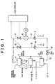
- Fig. 1 is a system diagram of a hydrogen absorbing tank apparatus according to a first embodiment, illustrating a hydrogen gas flow passage in particular.
- a hydrogen absorbing tank 1 contains a hydrogen absorbing alloy powder.
- the hydrogen absorbing tank 1 is connected to a hydrogen-oxygen fuel cell 2 and a radiator 3 by piping. Cooling water, that is, a heating medium, is circulated between the hydrogen absorbing tank 1, the fuel cell 2 and the radiator 3 by using valves and a circulating pump (not shown).
- heat generated by the fuel cell 2 is supplied to the hydrogen absorbing tank 1 in order to produce or release hydrogen gas from the hydrogen absorbing tank 1, and a surplus amount of heat is discharged through the radiator 3.
- Hydrogen gas from the hydrogen absorbing tank 1 is supplied to a compression passage P via a control valve 4, and also to a bypass passage B via a control valve 5.
- the compression passage P is provided with a compressor 6 for compressing hydrogen gas that flows in from the control valve 4, and a check valve 7 provided at an ejection side of the compressor 6 for preventing reverse flow of hydrogen gas.
- the bypass passage B is provided with a check valve 8 for preventing reverse flow of hydrogen gas. After the pressure of hydrogen gas from the compression passage P or the bypass passage B is adjusted by a pressure adjusting valve 9, hydrogen gas is introduced to an anode of the fuel cell 2.
- the compressor 6 is formed by a closed type compressor that has a built-in motor M.
- the compressor 6 has a high compression ratio. That is, the compressor 6 is capable of achieving a compression to or above a reference pressure of the fuel cell 2 (0.2 MPa in this embodiment) even if the hydrogen absorbing tank 1 is very cold.
- a controller 10 controls the control valves 4, 5 and also controls the operation of the motor M disposed within the compressor 6.
- a pressure sensor 11 detects the pressure in the hydrogen absorbing tank 1.
- a temperature sensor 12 detects the temperature of the hydrogen absorbing tank 1.
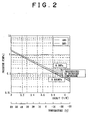
- Fig. 2 is a graph indicating temperature-equilibrium pressure characteristics of the hydrogen absorbing alloy powder contained in the hydrogen absorbing tank 1.
- a line ABS indicates a temperature-equilibrium pressure characteristic exhibited when hydrogen has been absorbed or occluded
- a line DES indicates a temperature-equilibrium pressure characteristic exhibited when hydrogen has been released.
- the graph of Fig. 2 indicates that the equilibrium pressure becomes lower than the reference pressure 0.2 MPa of the fuel cell 2 approximately at or below 0°C.
- the compressor 6 is operated if the temperature during a start-up is lower than 5°C (the equilibrium pressure is lower than about 0.3 MPa), taking into consideration a temperature drop of the hydrogen absorbing alloy powder due to hydrogen gas releasing heat.
- a control operation of the fuel cell apparatus including the hydrogen absorbing tank that is performed by the controller 10 will be described. Since the control operation is simple, no flowchart of the control operation is provided.
- the control valves 4, 5 are closed for safety reasons before the system is operated. At the start of operation, the control valves 4, 5 are opened.
- the pressure sensor 11 detects the pressure of the hydrogen absorbing tank 1, and the controller 10 determines whether the detected pressure is equal to or less than 0.3 MPa. If the detected pressure is equal to or less than 0.3 MPa, the controller 10 operates the compressor 6. The pressure of compressed hydrogen gas is adjusted to the reference pressure 0.2 MPa of the fuel cell 2 by the pressure adjusting valve 9. Hydrogen gas is then supplied to the fuel cell 2. At the same time, air at the same pressure is supplied to a cathode of the fuel cell 2, so that the fuel cell 2 is operated.
- the heating medium supplied from the fuel cell 2 to the hydrogen absorbing tank 1 is heated to a high temperature due to a temperature increase of the fuel cell 2, so that the heat medium heats the hydrogen absorbing alloy powder disposed in the hydrogen absorbing tank 1.
- the hydrogen gas releasing pressure of the hydrogen absorbing tank 1 becomes equal to or higher than 0.2 MPa and tends to rise, so that hydrogen gas is supplied to the fuel cell 2 via the check valve 8 of the bypass passage B.
- the controller 10 stops the compressor 6.
- the fuel cell 2 can be quickly started while the amount of supplemental energy added to the system is minimized.
- the pressure of hydrogen supplied from the hydrogen absorbing tank 1 is increased by the compressor 6 if the pressure is lower than a predetermined pressure.
- the case where the pressure in the hydrogen absorbing tank 1 is lower than the predetermined pressure includes a case where the amount of hydrogen stored in the hydrogen absorbing tank 1 has become small.
- the second embodiment has a construction similar to that of the first embodiment shown in Fig. 1, but is designed so that a heat medium from a hydrogen absorbing tank 1 cools the compressor 6 and the motor M.
- the second embodiment is able to prevent the overheating of the compressor 6 and the motor M and to achieve good supplemental heating of the hydrogen absorbing tank 1.
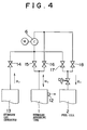
- the third embodiment is similar to the first embodiment, but differs as follows. That is, a hydrogen gas generator 13 that generates hydrogen gas by reforming methanol is added to the construction shown in Fig. 1.
- the hydrogen gas generator 13, a hydrogen absorbing tank 1 and a fuel cell 2 are connected to an input pipe of a compressor 6 via control valves 14, 15 and 17, respectively.
- the hydrogen absorbing tank 1 and the fuel cell 2 are also connected to an output pipe of the compressor 6 via control valves 16 and 18, respectively.
- the controller 10 determines that the hydrogen absorbing tank 1 has a low temperature, and is a case where the hydrogen gas pressure in the hydrogen absorbing tank 1 is lower than a predetermined pressure. In that case, the control valves 15, 18 are opened and the control valves 14, 16, 17 are closed, and the compressor 6 is operated, thereby increasing the pressure of hydrogen gas produced from the hydrogen absorbing tank 1 as in the first embodiment.
- the controller 10 determines that the hydrogen absorbing tank 1 has a high temperature, that is, when the hydrogen gas pressure in the hydrogen absorbing tank 1 is higher than the predetermined pressure, the control valves 15, 17 are opened and the control valves 14, 16, 18 are closed; alternatively, the control valves 16, 18 are opened and the control valves 14, 15, 17 are closed.
- the compressor 6 is then stopped. Therefore, hydrogen gas produced from the hydrogen absorbing tank 1 is supplied to the fuel cell 2 without being compressed.
- the controller 10 determines that the temperature detected by a temperature sensor (not shown) provided in the hydrogen gas generator 13 is higher than a predetermined value, that is, if the hydrogen gas generating pressure in the hydrogen gas generator 13 is higher than a predetermined pressure, the control valves 14, 15 are opened and the control valves 16, 17, 18 are closed so as to store hydrogen gas generated by the hydrogen gas generator 13 into the hydrogen absorbing tank 1 by absorption or occlusion.
- the controller 10 determines that the temperature of the hydrogen gas generator 13 is lower than the predetermined value, that is, if the hydrogen gas generating pressure in the hydrogen gas generator 13 is lower than the predetermined pressure, the control valves 14, 16 are opened to store hydrogen gas from the hydrogen gas generator 13 into the hydrogen absorbing tank 1.
- the compressor 6 is operated to supply temperature-increased hydrogen gas into the hydrogen absorbing tank 1.
- control valves 14, 17 are opened and the control valves 15, 16, 18 are closed.
- the control valves 14, 18 are opened so as to supply hydrogen gas from the hydrogen gas generator 13 to the fuel cell 2.
- the compressor 6 is operated to supply pressurized hydrogen gas to the fuel cell 2.
- the hydrogen gas generator 13 may be provided with a pressure sensor (not shown) instead of the temperature sensor. In that case, the operation of the compressor 6 may be determined by detecting the hydrogen gas generating pressure in the hydrogen gas generator 13.
- hydrogen gas can be moved by using the compressor 6 not only at the time of a low-temperature start of the hydrogen absorbing tank 1 but also in other occasions. Therefore, ease of use improves, and energy efficiency increases.
- the controller can be implemented as a programmed general purpose computer. It will be appreciated by those skilled in the art that the controller can be implemented using a single special purpose integrated circuit (e.g., ASIC) having a main or central processor section for overall, system-level control, and separate sections dedicated to performing various different specific computations, functions and other processes under control of the central processor section.
- the controller also can be a plurality of separate dedicated or programmable integrated or other electronic circuits or devices (e.g., hardwired electronic or logic circuits such as discrete element circuits, or programmable logic devices such as PLDs, PLAs, PALs or the like).
- the controller can be implemented using a suitably programmed general purpose computer, e.g., a microprocessor, microcontroller or other processor device (CPU or MPU), either alone or in conjunction with one or more peripheral (e.g., integrated circuit) data and signal processing devices.
- a suitably programmed general purpose computer e.g., a microprocessor, microcontroller or other processor device (CPU or MPU)
- CPU or MPU processor device
- peripheral e.g., integrated circuit
- any device or assembly of devices on which a finite state machine capable of implementing the processes described herein can be used as the controller.
- a distributed processing architecture can be used for maximum data/signal processing capability and speed.
- a gas compressor (6) and a bypass (B,8) that bypasses the gas compressor (6) are provided between a hydrogen absorbing tank (1) and a hydrogen gas consumer device (2) such as, for example, a fuel cell.
- a hydrogen gas consumer device (2) such as, for example, a fuel cell.
Abstract
Description
- The present invention relates to hydrogen absorbing tank apparatus.
- In a conventional art, when hydrogen gas that is stored by absorption or occlusion in a hydrogen absorbing tank is to be extracted from the tank and supplied to a fuel cell, the hydrogen absorbing tank needs to be heated by using hot water or the like in order to provide release heat for releasing hydrogen gas from a hydrogen absorbing material. For example, in a system where hydrogen gas is extracted from a hydrogen absorbing tank and supplied to a fuel cell, heat produced by the fuel cell is used to heat a hydrogen absorbing material disposed in the hydrogen absorbing tank.
- Furthermore, in order to ensure that the hydrogen gas producing pressure at which hydrogen gas is released from the hydrogen absorbing tank will be equal to or higher than a reference pressure of a hydrogen gas consumer device (e.g., the fuel cell), the hydrogen absorbing tank needs to be heated to a predetermined temperature when it is at a relatively low temperature or the like.
- In a fuel cell used as a source of drive energy for a vehicle, it is important to quickly supply hydrogen gas to the fuel cell to promptly cause the fuel cell to start generating power. However, if the hydrogen absorbing tank for supplying hydrogen gas to the fuel cell has a low temperature, for example, when the vehicle ambient temperature is low, the hydrogen producing pressure becomes low and the amount of hydrogen gas supplied to the fuel cell is low. In such a case, there is a danger of insufficient power generation, and also a danger of insufficient heat supply from the fuel cell to the hydrogen absorbing tank, which will result in a further delay of the start of power generation of the fuel cell. A delay of the start of power generation at the time of hydrogen release from the hydrogen absorbing tank also occurs when hydrogen gas is supplied from the hydrogen absorbing tank to a hydrogen gas consumer device other than a fuel cell for generating vehicle driving energy.
- A conceivable measure for improving the aforementioned situation at a low temperature is to employ a hydrogen absorbing material whose hydrogen producing pressure is high at low temperatures. However, if this measure is adopted, the hydrogen producing pressure becomes too high after the fuel cell is started up or when the ambient temperature is high. Therefore, this measure requires an increase of the pressure resistance of the hydrogen absorbing tank and limits the variety of hydrogen absorbing materials that can be used.
- Japanese Patent Application Laid-Open No. HEI 7-37598 proposes that a heating wire be added to a hydrogen absorbing tank so that the hydrogen absorbing tank can be heated by electrifying the electric heater (i.e., the heating wire).
- However, the supplemental electrical heating of a hydrogen absorbing tank has significant problems in safety and electric energy consumption. Normally, the amount of heat generated by a heating wire is considerably less than that generated by a hydrogen gas consumer device such as a fuel cell or the like. Therefore, the supplemental electrical heating only slightly accelerates the heating of a fuel cell; that is, the heating rate is increased only slightly from the level achieved without the supplemental electrical heating.
- As another conceivable measure, a burner capable of producing larger amounts of heat than an electric heater may be externally provided so that combustion gas from the burner is used to heat a hydrogen absorbing tank. However, this measure causes problems of fuel storage requirement, complication of the system, degradation of safety, deterioration of efficiency, and the like.
- Accordingly, it is one object of the present invention to provide a hydrogen absorbing tank apparatus that is excellent in energy conservation and also excellent in its low-temperature starting performance.
- The above object is accomplished by combination of features of the independent claim and the dependent claims that disclose further advantageous embodiments of the invention.
- In accordance with one aspect of the invention, a hydrogen absorbing tank apparatus includes a hydrogen absorbing tank containing a hydrogen absorbing material that allows hydrogen gas to move into the hydrogen absorbing tank from an outside thereof and to move out of the hydrogen absorbing tank. A gas compressor is disposed between the hydrogen absorbing tank and a hydrogen gas consumer device. The gas compressor compresses hydrogen gas at least to a predetermined reference pressure of the hydrogen gas consumer device. A bypass device that opens only when a hydrogen gas producing pressure of the hydrogen absorbing tank is higher than the reference pressure is connected in parallel to the gas compressor. A controller operates the gas compressor to compress hydrogen gas from the hydrogen absorbing tank at least to the reference pressure when the hydrogen absorbing tank has a low temperature and the hydrogen gas producing pressure is lower than the reference pressure despite an operation of the hydrogen gas consumer device. Therefore, when the temperature of the hydrogen absorbing tank is low and the hydrogen gas producing pressure during an early period of the hydrogen gas releasing operation is low, the gas compressor is operated. When the temperature of the hydrogen absorbing tank subsequently increases to a sufficiently high temperature due to normalization of the operation of the hydrogen gas consumer device and the like, the gas compressor is stopped and hydrogen gas is supplied to the hydrogen gas consumer device via the bypass device.
- In this construction, a supplemental power supplied by the gas compressor during an early period of start-up is provided in the form of a substantially adiabatic thermal compression work of hydrogen gas. Therefore, the amount of supplemental energy needed becomes considerably small in comparison with a conventional construction in which a supplemental energy is provided by an electric heater in the form of an isobaric heating of hydrogen gas. Therefore, the invention prevents stored power from being wasted, and realizes size and weight reductions of a storage battery.
- A time lag between start of the gas compressor and production of hydrogen gas at a necessary pressure is significantly shorter than the time lag occurring in a case where the temperature of the hydrogen absorbing tank is raised by an electric heater. Therefore, the hydrogen absorbing tank apparatus of the invention is particularly suitable to a system that needs a quick start, for example, an electric vehicle.
- The gas compressor and a prime motor (typically, an electric motor) employed in a construction according to the invention need only to supply hydrogen gas during start-up of the hydrogen absorbing tank or the hydrogen gas consumer device. The gas compressor and the prime motor may be designed merely for short-time operation. Furthermore, the gas compressor and the motor do not need to have capacity corresponding to the full-load operation of the hydrogen absorbing tank or the hydrogen gas consumer device. Therefore, size reductions of the gas compressor and the motor are possible. It is not necessary to provide a very large load increase.
- Furthermore, the construction of the invention makes it possible for the hydrogen absorbing tank to produce a necessary hydrogen gas producing pressure and also makes it possible to supply hydrogen gas via the bypass passage. Therefore, the invention eliminates the need to operate the gas compressor when the hydrogen absorbing tank is producing a necessary hydrogen gas producing pressure, which is undesirable and wastes power. The invention thus achieves high efficiency.
- The hydrogen gas consumer device may be a fuel cell from which heat is supplied to the hydrogen absorbing tank. Therefore, quick start of the fuel cell can be realized. The amount of heat quickly generated by the fuel cell can be used to heat the hydrogen absorbing tank so as to accelerate the start-up of the hydrogen absorbing tank. Furthermore, power generated by the fuel cell can be used to operate the gas compressor, so that a battery for storing power for temporary operation of the gas compressor can be reduced in size.
- Heat generated by the gas compressor or the motor that operates the gas compressor may be supplied to the fuel cell or to the hydrogen absorbing tank by using a heating medium. This construction will further improve start-up performance.
- If the hydrogen gas producing pressure of the hydrogen absorbing tank has decreased due to a decrease in the amount of hydrogen stored in the hydrogen absorbing tank, the gas compressor may be operated for supplemental pressurization of hydrogen gas supplied to the hydrogen gas consumer device. This construction increases the utilization rate (effective hydrogen absorbing capacity) of the hydrogen absorbing tank.
- Furthermore, if the hydrogen gas producing pressure of a hydrogen gas generator device that supplies hydrogen gas to the hydrogen absorbing tank is lower than the hydrogen absorbing pressure of the hydrogen absorbing tank, hydrogen gas supplied from the hydrogen gas generator device to the hydrogen absorbing tank may be pressurized. This construction increases the operation efficiency of the gas compressor.
- Further, even if the hydrogen gas producing pressure of the hydrogen gas generator device is higher than the hydrogen absorbing pressure of the hydrogen absorbing tank, the gas compressor may be operated so that hydrogen gas is absorbed into the hydrogen absorbing tank at an increased pressure. Particularly, during an ending period of the absorption and storage period of the hydrogen absorbing tank, hydrogen gas produced from the hydrogen gas generator device may be pressurized by the gas compressor and then absorbed and stored into the hydrogen absorbing tank. In this manner, a further increased amount of hydrogen gas can be absorbed and stored into the hydrogen absorbing tank. Furthermore, during an initial period (during startup) of the subsequent hydrogen gas release from the hydrogen absorbing tank to the hydrogen gas consumer device, sufficiently high-pressure hydrogen gas can be released even if the temperature is low. Therefore, the start-up of the hydrogen absorbing tank and the hydrogen gas consumer device can be further accelerated.
- Further, if the hydrogen gas producing pressure of the hydrogen gas generator device that supplies hydrogen gas to the hydrogen absorbing tank is lower than the reference pressure of the hydrogen gas consumer device (for example, during start-up of the hydrogen gas generator device or the like), hydrogen gas supplied from the hydrogen gas generator device to the hydrogen gas consumer device may be pressurized. This construction improves the operation efficiency of the gas compressor.
- This summary of the invention does not necessarily describe all necessary features so that the invention may also reside in a sub-combination of these described features.
- The foregoing and further objects, features and advantages of the present invention will become apparent from the following description of preferred embodiments with reference to the accompanying drawings, wherein like numerals are used to represent like elements and wherein:
- Fig. 1 is a system diagram of a hydrogen gas piping illustrating a first embodiment of the hydrogen absorbing tank apparatus of the invention;
- Fig. 2 indicates temperature-equilibrium pressure characteristics of a hydrogen absorbing alloy powder used in the first embodiment;
- Fig. 3 is a diagram of a hydrogen gas piping illustrating a second embodiment of the hydrogen absorbing tank apparatus of the invention; and
- Fig. 4 is a diagram of a hydrogen gas piping illustrating a third embodiment of the hydrogen absorbing tank apparatus of the invention.
-
- Preferred embodiments of the present invention will be described in detail hereinafter with reference to the accompanying drawings.
- Fig. 1 is a system diagram of a hydrogen absorbing tank apparatus according to a first embodiment, illustrating a hydrogen gas flow passage in particular.
- Referring to Fig. 1, a
hydrogen absorbing tank 1 contains a hydrogen absorbing alloy powder. Thehydrogen absorbing tank 1 is connected to a hydrogen-oxygen fuel cell 2 and aradiator 3 by piping. Cooling water, that is, a heating medium, is circulated between thehydrogen absorbing tank 1, thefuel cell 2 and theradiator 3 by using valves and a circulating pump (not shown). During a normal power generating operation, heat generated by thefuel cell 2 is supplied to thehydrogen absorbing tank 1 in order to produce or release hydrogen gas from thehydrogen absorbing tank 1, and a surplus amount of heat is discharged through theradiator 3. - Hydrogen gas from the
hydrogen absorbing tank 1 is supplied to a compression passage P via acontrol valve 4, and also to a bypass passage B via a control valve 5. The compression passage P is provided with acompressor 6 for compressing hydrogen gas that flows in from thecontrol valve 4, and acheck valve 7 provided at an ejection side of thecompressor 6 for preventing reverse flow of hydrogen gas. The bypass passage B is provided with acheck valve 8 for preventing reverse flow of hydrogen gas. After the pressure of hydrogen gas from the compression passage P or the bypass passage B is adjusted by a pressure adjusting valve 9, hydrogen gas is introduced to an anode of thefuel cell 2. - The
compressor 6 is formed by a closed type compressor that has a built-in motor M. Thecompressor 6 has a high compression ratio. That is, thecompressor 6 is capable of achieving a compression to or above a reference pressure of the fuel cell 2 (0.2 MPa in this embodiment) even if thehydrogen absorbing tank 1 is very cold. - A
controller 10 controls thecontrol valves 4, 5 and also controls the operation of the motor M disposed within thecompressor 6. Apressure sensor 11 detects the pressure in thehydrogen absorbing tank 1. Atemperature sensor 12 detects the temperature of thehydrogen absorbing tank 1. - Fig. 2 is a graph indicating temperature-equilibrium pressure characteristics of the hydrogen absorbing alloy powder contained in the
hydrogen absorbing tank 1. In Fig. 2, a line ABS indicates a temperature-equilibrium pressure characteristic exhibited when hydrogen has been absorbed or occluded, and a line DES indicates a temperature-equilibrium pressure characteristic exhibited when hydrogen has been released. The graph of Fig. 2 indicates that the equilibrium pressure becomes lower than the reference pressure 0.2 MPa of thefuel cell 2 approximately at or below 0°C. In this embodiment, thecompressor 6 is operated if the temperature during a start-up is lower than 5°C (the equilibrium pressure is lower than about 0.3 MPa), taking into consideration a temperature drop of the hydrogen absorbing alloy powder due to hydrogen gas releasing heat. - A control operation of the fuel cell apparatus including the hydrogen absorbing tank that is performed by the
controller 10 will be described. Since the control operation is simple, no flowchart of the control operation is provided. Thecontrol valves 4, 5 are closed for safety reasons before the system is operated. At the start of operation, thecontrol valves 4, 5 are opened. - At a start of the apparatus, the
pressure sensor 11 detects the pressure of thehydrogen absorbing tank 1, and thecontroller 10 determines whether the detected pressure is equal to or less than 0.3 MPa. If the detected pressure is equal to or less than 0.3 MPa, thecontroller 10 operates thecompressor 6. The pressure of compressed hydrogen gas is adjusted to the reference pressure 0.2 MPa of thefuel cell 2 by the pressure adjusting valve 9. Hydrogen gas is then supplied to thefuel cell 2. At the same time, air at the same pressure is supplied to a cathode of thefuel cell 2, so that thefuel cell 2 is operated. - After that, the heating medium supplied from the
fuel cell 2 to thehydrogen absorbing tank 1 is heated to a high temperature due to a temperature increase of thefuel cell 2, so that the heat medium heats the hydrogen absorbing alloy powder disposed in thehydrogen absorbing tank 1. Then, the hydrogen gas releasing pressure of thehydrogen absorbing tank 1 becomes equal to or higher than 0.2 MPa and tends to rise, so that hydrogen gas is supplied to thefuel cell 2 via thecheck valve 8 of the bypass passage B. - If the hydrogen gas releasing pressure is equal to or higher than 0.25 MPa and tends to rise after a predetermined length of time elapses following the start of operation, the
controller 10 stops thecompressor 6. - Through this control operation, the
fuel cell 2 can be quickly started while the amount of supplemental energy added to the system is minimized. - In this embodiment, the pressure of hydrogen supplied from the
hydrogen absorbing tank 1 is increased by thecompressor 6 if the pressure is lower than a predetermined pressure. The case where the pressure in thehydrogen absorbing tank 1 is lower than the predetermined pressure includes a case where the amount of hydrogen stored in thehydrogen absorbing tank 1 has become small. - A second embodiment will be described with reference to Fig. 3.
- The second embodiment has a construction similar to that of the first embodiment shown in Fig. 1, but is designed so that a heat medium from a
hydrogen absorbing tank 1 cools thecompressor 6 and the motor M. - Therefore, the second embodiment is able to prevent the overheating of the
compressor 6 and the motor M and to achieve good supplemental heating of thehydrogen absorbing tank 1. - A third embodiment will be described with reference to Fig. 4.
- The third embodiment is similar to the first embodiment, but differs as follows. That is, a
hydrogen gas generator 13 that generates hydrogen gas by reforming methanol is added to the construction shown in Fig. 1. Thehydrogen gas generator 13, ahydrogen absorbing tank 1 and afuel cell 2 are connected to an input pipe of acompressor 6 viacontrol valves hydrogen absorbing tank 1 and thefuel cell 2 are also connected to an output pipe of thecompressor 6 viacontrol valves - The operation of this hydrogen gas generator-hydrogen absorbing tank-fuel cell system will be described.
- The flowing of fluid into and out of the
hydrogen absorbing tank 1, thefuel cell 2 and thehydrogen gas generator 13 will be described only with reference to hydrogen gas, and will not be described with respect to other fluids. - When the temperature detected by the
temperature sensor 12 provided in thehydrogen absorbing tank 1 is low, thecontroller 10 determines that thehydrogen absorbing tank 1 has a low temperature, and is a case where the hydrogen gas pressure in thehydrogen absorbing tank 1 is lower than a predetermined pressure. In that case, thecontrol valves control valves compressor 6 is operated, thereby increasing the pressure of hydrogen gas produced from thehydrogen absorbing tank 1 as in the first embodiment. - When the
controller 10 determines that thehydrogen absorbing tank 1 has a high temperature, that is, when the hydrogen gas pressure in thehydrogen absorbing tank 1 is higher than the predetermined pressure, thecontrol valves control valves control valves control valves compressor 6 is then stopped. Therefore, hydrogen gas produced from thehydrogen absorbing tank 1 is supplied to thefuel cell 2 without being compressed. - When the
controller 10 determines that the temperature detected by a temperature sensor (not shown) provided in thehydrogen gas generator 13 is higher than a predetermined value, that is, if the hydrogen gas generating pressure in thehydrogen gas generator 13 is higher than a predetermined pressure, thecontrol valves control valves hydrogen gas generator 13 into thehydrogen absorbing tank 1 by absorption or occlusion. - When the
controller 10 determines that the temperature of thehydrogen gas generator 13 is lower than the predetermined value, that is, if the hydrogen gas generating pressure in thehydrogen gas generator 13 is lower than the predetermined pressure, thecontrol valves hydrogen gas generator 13 into thehydrogen absorbing tank 1. Thecompressor 6 is operated to supply temperature-increased hydrogen gas into thehydrogen absorbing tank 1. - To supply the
fuel cell 2 with hydrogen gas from thehydrogen gas generator 13 in a case where the temperature of thehydrogen gas generator 13 is high, thecontrol valves control valves - When the temperature of the
hydrogen gas generator 13 is low, that is, when the hydrogen gas generating pressure is low and the reference pressure to thefuel cell 2 is low, thecontrol valves hydrogen gas generator 13 to thefuel cell 2. Thecompressor 6 is operated to supply pressurized hydrogen gas to thefuel cell 2. - The
hydrogen gas generator 13 may be provided with a pressure sensor (not shown) instead of the temperature sensor. In that case, the operation of thecompressor 6 may be determined by detecting the hydrogen gas generating pressure in thehydrogen gas generator 13. - In this embodiment, hydrogen gas can be moved by using the
compressor 6 not only at the time of a low-temperature start of thehydrogen absorbing tank 1 but also in other occasions. Therefore, ease of use improves, and energy efficiency increases. - The controller (controller 10) can be implemented as a programmed general purpose computer. It will be appreciated by those skilled in the art that the controller can be implemented using a single special purpose integrated circuit (e.g., ASIC) having a main or central processor section for overall, system-level control, and separate sections dedicated to performing various different specific computations, functions and other processes under control of the central processor section. The controller also can be a plurality of separate dedicated or programmable integrated or other electronic circuits or devices (e.g., hardwired electronic or logic circuits such as discrete element circuits, or programmable logic devices such as PLDs, PLAs, PALs or the like). The controller can be implemented using a suitably programmed general purpose computer, e.g., a microprocessor, microcontroller or other processor device (CPU or MPU), either alone or in conjunction with one or more peripheral (e.g., integrated circuit) data and signal processing devices. In general, any device or assembly of devices on which a finite state machine capable of implementing the processes described herein can be used as the controller. A distributed processing architecture can be used for maximum data/signal processing capability and speed.
- While the present invention has been described with reference to preferred embodiments thereof, it is to be understood that the invention is not limited to the disclosed embodiments or constructions. To the contrary, the invention is intended to cover various modifications and equivalent arrangements. In addition, while the various elements of the disclosed invention are shown in various combinations and configurations, which are exemplary, other combinations and configurations, including more, less or only a single element, are also within the spirit and scope of the invention.
- A gas compressor (6) and a bypass (B,8) that bypasses the gas compressor (6) are provided between a hydrogen absorbing tank (1) and a hydrogen gas consumer device (2) such as, for example, a fuel cell. When the hydrogen gas generating pressure is low during an initial period of the hydrogen gas releasing operation of the hydrogen absorbing tank (1), the gas compressor (6) is operated. When the hydrogen gas generating pressure of the hydrogen absorbing tank (1) becomes sufficiently high due to normalization of the operation of the fuel cell or the like, the gas compressor (6) is stopped, and hydrogen gas is supplied to the fuel cell via the bypass (B,8).
Claims (9)
- A hydrogen absorbing tank apparatus comprising:a hydrogen absorbing tank (1) containing a hydrogen absorbing material that allows hydrogen gas to move into the hydrogen absorbing tank from an outside thereof and to move out of the hydrogen absorbing tank; anda gas compressor (6) disposed between the hydrogen absorbing tank (1) and a hydrogen gas consumer device (2), the gas compressor compressing the hydrogen gas output from the hydrogen absorbing tank (1) at least to a predetermined reference pressure of the hydrogen gas consumer device (2), characterized by further comprising:a bypass means (B, 8) that opens only when a hydrogen gas generating pressure of the hydrogen absorbing tank (1) is higher tan the predetermined reference pressure, the bypass means connected between the hydrogen absorbing tank (1) and the hydrogen gas consumer device (2) in parallel to the gas compressor (6); anda controller (10) that operates the gas compressor (6) to compress hydrogen gas output from the hydrogen absorbing tank at least to the predetermined reference pressure when the hydrogen absorbing tank (1) has a low temperature and the hydrogen gas generating pressure of the hydrogen absorbing tank (1) is lower than the predetermined reference pressure.
- A hydrogen absorbing tank apparatus according to claim 1, characterized in that:the hydrogen absorbing tank (1) has a temperature sensor (12), andthe controller (10) determines whether the hydrogen gas generating pressure is lower than the predetermined reference pressure based on a temperature detected by the temperature sensor (12).
- A hydrogen absorbing tank apparatus according to claim 1, characterized in that:the hydrogen absorbing tank (1) has a pressure sensor (11), andthe controller (10) determines whether the hydrogen gas generating pressure is lower than the predetermined reference pressure based on a pressure detected by the pressure sensor (11).
- A hydrogen absorbing tank apparatus according to claim 1, characterized in that:the hydrogen gas consumer device (2) includes a fuel cell (2) from which heat is supplied to the hydrogen absorbing tank (1), andthe controller (10) operates the gas compressor (6) during an initial period of operation of the fuel cell.
- A hydrogen absorbing tank apparatus according to claim 4, characterized in that at least one of the gas compressor (6) and a motor that operates the gas compressor is connected to at least one of the fuel cell (2) and the hydrogen absorbing tank (1) by a heating medium circulating passage in which a heating medium circulates, and the at least one of the fuel cell (2) and the hydrogen absorbing tank (1) is heated by the heating medium heated by the at least one of the gas compressor (6) and the motor that operates the gas compressor.
- A hydrogen absorbing tank apparatus according to claim 4, characterized in that the controller (10) operates the gas compressor (6) when an amount of hydrogen stored in the hydrogen absorbing tank (1) has decreased and the hydrogen gas generating pressure of the hydrogen absorbing tank (1) has decreased.
- A hydrogen absorbing tank apparatus according to claim 4, characterized by further comprising a hydrogen gas generator that supplies hydrogen gas to the hydrogen absorbing tank (1), whereinwhen a hydrogen gas generating pressure of the hydrogen gas generator is lower than a predetermined pressure, the controller (10) increases, by using the gas compressor (6), a pressure of hydrogen gas supplied from the hydrogen gas generator to the hydrogen absorbing tank (1).
- A hydrogen absorbing tank apparatus according to claim 4, characterized by further comprising a hydrogen gas generator that supplies hydrogen gas to the hydrogen gas consumer device (2), whereinwhen a hydrogen gas generating pressure of the hydrogen gas generator device is lower than the reference pressure of the hydrogen gas consumer device (2), the controller (10) increases, by using the gas compressor (6), a pressure of hydrogen gas supplied from the hydrogen gas generator to the hydrogen consumer device (2).
- A hydrogen absorbing tank apparatus according to claim 1, characterized in that the bypass means (B, 8) includes a bypass passage (B) that bypasses the gas compressor, and a valve (8) provided in the bypass passage, the valve being openable at a predetermined pressure.
Applications Claiming Priority (2)
| Application Number | Priority Date | Filing Date | Title |
|---|---|---|---|
| JP27099598 | 1998-09-25 | ||
| JP27099598A JP4213267B2 (en) | 1998-09-25 | 1998-09-25 | Hydrogen storage tank device |
Publications (3)
| Publication Number | Publication Date |
|---|---|
| EP0989290A2 true EP0989290A2 (en) | 2000-03-29 |
| EP0989290A3 EP0989290A3 (en) | 2001-01-03 |
| EP0989290B1 EP0989290B1 (en) | 2004-03-17 |
Family
ID=17493944
Family Applications (1)
| Application Number | Title | Priority Date | Filing Date |
|---|---|---|---|
| EP99118838A Expired - Lifetime EP0989290B1 (en) | 1998-09-25 | 1999-09-24 | Hydrogen absorbing tank apparatus |
Country Status (5)
| Country | Link |
|---|---|
| US (1) | US6890490B1 (en) |
| EP (1) | EP0989290B1 (en) |
| JP (1) | JP4213267B2 (en) |
| CA (1) | CA2282985C (en) |
| DE (1) | DE69915557T2 (en) |
Cited By (5)
| Publication number | Priority date | Publication date | Assignee | Title |
|---|---|---|---|---|
| WO2005048386A1 (en) * | 2003-11-06 | 2005-05-26 | Daimlerchrysler Ag | Fuel cell system which can be used in a mobile manner with an adsorption accumulator |
| WO2006017449A2 (en) * | 2004-08-03 | 2006-02-16 | General Motors Corporation | Pressurized hydrogen delivery system for electrochemical cells |
| US7521036B2 (en) | 2004-02-26 | 2009-04-21 | General Motors Corporation | Hydrogen storage materials and methods including hydrides and hydroxides |
| US7601329B2 (en) | 2004-02-26 | 2009-10-13 | Gm Global Technology Operations, Inc. | Regeneration of hydrogen storage system materials and methods including hydrides and hydroxides |
| US7959896B2 (en) | 2004-02-26 | 2011-06-14 | GM Global Technology Operations LLC | Hydrogen storage system materials and methods including hydrides and hydroxides |
Families Citing this family (14)
| Publication number | Priority date | Publication date | Assignee | Title |
|---|---|---|---|---|
| JP4655355B2 (en) * | 2000-11-20 | 2011-03-23 | ソニー株式会社 | Power generation device and hydrogen cartridge used therefor |
| ATE382545T1 (en) * | 2002-10-24 | 2008-01-15 | Airbus Gmbh | ARRANGEMENT FOR GENERATING WATER ON BOARD AN AIRCRAFT |
| US6899490B2 (en) * | 2003-03-11 | 2005-05-31 | B.R. Lee Industries, Inc. | Cut off and strike off mechanism for a paving machine |
| JP4675029B2 (en) * | 2003-03-17 | 2011-04-20 | トヨタ自動車株式会社 | Fuel cell system and hydrogen storage method |
| US20050244241A1 (en) * | 2004-04-30 | 2005-11-03 | Joichi Miyazaki | Cooling system, cooling method, and electronic apparatus |
| JP2006040597A (en) * | 2004-07-23 | 2006-02-09 | Mitsubishi Heavy Ind Ltd | Gas supply system, energy supply system and gas supply method |
| US7574996B2 (en) * | 2007-10-23 | 2009-08-18 | Gm Global Technology Operations, Inc. | Fuel supply system with a gas adsorption device |
| GB0818799D0 (en) | 2008-10-14 | 2008-11-19 | Agco Sa | Vehicle powered by hydrogen fuel cell and system for fuelling such vehicle |
| CN104114955A (en) * | 2012-02-29 | 2014-10-22 | 吉坤日矿日石能源株式会社 | Method for controlling and device for controlling cogeneration system |
| US20160197323A1 (en) | 2015-01-05 | 2016-07-07 | Johnson Controls Technology Company | Battery module vent and handle configuration system and method |
| US10337459B2 (en) * | 2015-02-13 | 2019-07-02 | GM Global Technology Operations LLC | Natural gas fueled vehicle |
| DE102015209870A1 (en) * | 2015-05-29 | 2016-12-01 | Robert Bosch Gmbh | Process for refueling hydrogen vehicles and home-filling system therefor |
| CN109163214B (en) * | 2018-08-15 | 2024-01-05 | 国家电投集团氢能科技发展有限公司 | Hydrogenation station |
| US11242816B1 (en) * | 2020-10-15 | 2022-02-08 | Caterpillar Inc. | Systems and methods for reverse flow detect |
Citations (3)
| Publication number | Priority date | Publication date | Assignee | Title |
|---|---|---|---|---|
| US4085709A (en) * | 1975-12-04 | 1978-04-25 | Kuldip Chand Tangri | Hydrogen fuel system for a vehicle |
| JPH0737598A (en) * | 1993-07-23 | 1995-02-07 | Yamaha Motor Co Ltd | Hydrogen gas supplier for fuel cell |
| US5678410A (en) * | 1993-08-06 | 1997-10-21 | Toyota Jidosha Kabushiki Kaisha | Combined system of fuel cell and air-conditioning apparatus |
Family Cites Families (3)
| Publication number | Priority date | Publication date | Assignee | Title |
|---|---|---|---|---|
| JP2883789B2 (en) | 1993-08-06 | 1999-04-19 | 株式会社豊田自動織機製作所 | Hydrogen fueled vehicles |
| JP3512448B2 (en) | 1993-09-28 | 2004-03-29 | 株式会社豊田中央研究所 | Combined fuel cell and cooling system |
| JPH1064567A (en) | 1996-06-14 | 1998-03-06 | Matsushita Electric Ind Co Ltd | Fuel cell hydrogen supply system and portable electrical machinery and apparatus |
-
1998
- 1998-09-25 JP JP27099598A patent/JP4213267B2/en not_active Expired - Fee Related
-
1999
- 1999-09-16 US US09/397,287 patent/US6890490B1/en not_active Expired - Fee Related
- 1999-09-21 CA CA002282985A patent/CA2282985C/en not_active Expired - Fee Related
- 1999-09-24 DE DE69915557T patent/DE69915557T2/en not_active Expired - Lifetime
- 1999-09-24 EP EP99118838A patent/EP0989290B1/en not_active Expired - Lifetime
Patent Citations (3)
| Publication number | Priority date | Publication date | Assignee | Title |
|---|---|---|---|---|
| US4085709A (en) * | 1975-12-04 | 1978-04-25 | Kuldip Chand Tangri | Hydrogen fuel system for a vehicle |
| JPH0737598A (en) * | 1993-07-23 | 1995-02-07 | Yamaha Motor Co Ltd | Hydrogen gas supplier for fuel cell |
| US5678410A (en) * | 1993-08-06 | 1997-10-21 | Toyota Jidosha Kabushiki Kaisha | Combined system of fuel cell and air-conditioning apparatus |
Non-Patent Citations (1)
| Title |
|---|
| PATENT ABSTRACTS OF JAPAN vol. 1995, no. 05, 30 June 1995 (1995-06-30) & JP 07 037598 A (YAMAHA MOTOR CO LTD), 7 February 1995 (1995-02-07) * |
Cited By (8)
| Publication number | Priority date | Publication date | Assignee | Title |
|---|---|---|---|---|
| WO2005048386A1 (en) * | 2003-11-06 | 2005-05-26 | Daimlerchrysler Ag | Fuel cell system which can be used in a mobile manner with an adsorption accumulator |
| US8067121B2 (en) | 2003-11-06 | 2011-11-29 | Daimler Ag | Fuel cell system which can be used in a mobile manner with an adsorption accumulator |
| US7521036B2 (en) | 2004-02-26 | 2009-04-21 | General Motors Corporation | Hydrogen storage materials and methods including hydrides and hydroxides |
| US7601329B2 (en) | 2004-02-26 | 2009-10-13 | Gm Global Technology Operations, Inc. | Regeneration of hydrogen storage system materials and methods including hydrides and hydroxides |
| US7959896B2 (en) | 2004-02-26 | 2011-06-14 | GM Global Technology Operations LLC | Hydrogen storage system materials and methods including hydrides and hydroxides |
| WO2006017449A2 (en) * | 2004-08-03 | 2006-02-16 | General Motors Corporation | Pressurized hydrogen delivery system for electrochemical cells |
| WO2006017449A3 (en) * | 2004-08-03 | 2007-04-19 | Gen Motors Corp | Pressurized hydrogen delivery system for electrochemical cells |
| CN101068746B (en) * | 2004-08-03 | 2012-02-08 | 通用汽车公司 | Pressurized hydrogen delivery system for electrochemical cells |
Also Published As
| Publication number | Publication date |
|---|---|
| EP0989290B1 (en) | 2004-03-17 |
| JP2000100461A (en) | 2000-04-07 |
| JP4213267B2 (en) | 2009-01-21 |
| EP0989290A3 (en) | 2001-01-03 |
| DE69915557T2 (en) | 2005-02-03 |
| CA2282985A1 (en) | 2000-03-25 |
| DE69915557D1 (en) | 2004-04-22 |
| US6890490B1 (en) | 2005-05-10 |
| CA2282985C (en) | 2004-06-22 |
Similar Documents
| Publication | Publication Date | Title |
|---|---|---|
| EP0989290B1 (en) | Hydrogen absorbing tank apparatus | |
| US20060147772A1 (en) | Fuel cell system | |
| CN101128952B (en) | Method of using hydrogen storage tank and hydrogen storage tank | |
| JP3870665B2 (en) | Fuel cell system | |
| JP5147831B2 (en) | Hydrogen consumption system and operation method thereof | |
| US20080044704A1 (en) | Fuel Cell System | |
| US8841040B2 (en) | Method to cold-start fuel cell system at sub-zero temperatures | |
| KR20120031464A (en) | Rankine cycle system | |
| JP2002222658A (en) | Fuel cell system | |
| US20090320503A1 (en) | Cogeneration system | |
| CN112349927A (en) | All-weather quick-response solid-state hydrogen storage fuel cell power system and starting method | |
| JP2000100461A5 (en) | ||
| JP4432603B2 (en) | Fuel cell device for vehicles | |
| JP5799766B2 (en) | Fuel cell system | |
| JP4575693B2 (en) | Fuel cell system | |
| JP2001302201A (en) | Apparatus for storing and supplying hydrogen, fuel cell system, and movable body carrying the same | |
| JP2018041630A (en) | Fuel cell system | |
| JP3871792B2 (en) | Fuel cell device | |
| JP4014730B2 (en) | Fuel cell system | |
| US7083874B2 (en) | Fuel cell power generation system | |
| KR101240974B1 (en) | Fuel cell system having cooling water heating apparatus for fuel cell having bypass structure | |
| KR101091681B1 (en) | Fuel cell cold starting device and method using adiabatic air compression | |
| JP4673617B2 (en) | Fuel cell system and control method thereof | |
| JP2002081597A (en) | Hydrogen storage system | |
| JPH0275165A (en) | Temperature adjusting device for fuel cell |
Legal Events
| Date | Code | Title | Description |
|---|---|---|---|
| PUAI | Public reference made under article 153(3) epc to a published international application that has entered the european phase |
Free format text: ORIGINAL CODE: 0009012 |
|
| 17P | Request for examination filed |
Effective date: 19990929 |
|
| AK | Designated contracting states |
Kind code of ref document: A2 Designated state(s): DE FR GB IT |
|
| AX | Request for extension of the european patent |
Free format text: AL;LT;LV;MK;RO;SI |
|
| PUAL | Search report despatched |
Free format text: ORIGINAL CODE: 0009013 |
|
| AK | Designated contracting states |
Kind code of ref document: A3 Designated state(s): AT BE CH CY DE DK ES FI FR GB GR IE IT LI LU MC NL PT SE |
|
| AX | Request for extension of the european patent |
Free format text: AL;LT;LV;MK;RO;SI |
|
| RIC1 | Information provided on ipc code assigned before grant |
Free format text: 7F 02B 43/10 A, 7F 17C 11/00 B, 7H 01M 8/06 B |
|
| AKX | Designation fees paid |
Free format text: DE FR GB IT |
|
| 17Q | First examination report despatched |
Effective date: 20020523 |
|
| GRAP | Despatch of communication of intention to grant a patent |
Free format text: ORIGINAL CODE: EPIDOSNIGR1 |
|
| GRAS | Grant fee paid |
Free format text: ORIGINAL CODE: EPIDOSNIGR3 |
|
| GRAA | (expected) grant |
Free format text: ORIGINAL CODE: 0009210 |
|
| AK | Designated contracting states |
Kind code of ref document: B1 Designated state(s): DE FR GB IT |
|
| REG | Reference to a national code |
Ref country code: GB Ref legal event code: FG4D |
|
| REF | Corresponds to: |
Ref document number: 69915557 Country of ref document: DE Date of ref document: 20040422 Kind code of ref document: P |
|
| ET | Fr: translation filed | ||
| PLBE | No opposition filed within time limit |
Free format text: ORIGINAL CODE: 0009261 |
|
| STAA | Information on the status of an ep patent application or granted ep patent |
Free format text: STATUS: NO OPPOSITION FILED WITHIN TIME LIMIT |
|
| 26N | No opposition filed |
Effective date: 20041220 |
|
| REG | Reference to a national code |
Ref country code: GB Ref legal event code: 746 Effective date: 20071206 |
|
| PGFP | Annual fee paid to national office [announced via postgrant information from national office to epo] |
Ref country code: GB Payment date: 20090923 Year of fee payment: 11 |
|
| PGFP | Annual fee paid to national office [announced via postgrant information from national office to epo] |
Ref country code: DE Payment date: 20090917 Year of fee payment: 11 |
|
| PGFP | Annual fee paid to national office [announced via postgrant information from national office to epo] |
Ref country code: IT Payment date: 20090917 Year of fee payment: 11 Ref country code: FR Payment date: 20091012 Year of fee payment: 11 |
|
| GBPC | Gb: european patent ceased through non-payment of renewal fee |
Effective date: 20100924 |
|
| PG25 | Lapsed in a contracting state [announced via postgrant information from national office to epo] |
Ref country code: IT Free format text: LAPSE BECAUSE OF NON-PAYMENT OF DUE FEES Effective date: 20100924 |
|
| REG | Reference to a national code |
Ref country code: FR Ref legal event code: ST Effective date: 20110531 |
|
| REG | Reference to a national code |
Ref country code: DE Ref legal event code: R119 Ref document number: 69915557 Country of ref document: DE Effective date: 20110401 |
|
| PG25 | Lapsed in a contracting state [announced via postgrant information from national office to epo] |
Ref country code: FR Free format text: LAPSE BECAUSE OF NON-PAYMENT OF DUE FEES Effective date: 20100930 Ref country code: DE Free format text: LAPSE BECAUSE OF NON-PAYMENT OF DUE FEES Effective date: 20110401 |
|
| PG25 | Lapsed in a contracting state [announced via postgrant information from national office to epo] |
Ref country code: GB Free format text: LAPSE BECAUSE OF NON-PAYMENT OF DUE FEES Effective date: 20100924 |