EP0986876B1 - Automated home control system using existing electrical lines as a communication medium - Google Patents
Automated home control system using existing electrical lines as a communication medium Download PDFInfo
- Publication number
- EP0986876B1 EP0986876B1 EP98930189A EP98930189A EP0986876B1 EP 0986876 B1 EP0986876 B1 EP 0986876B1 EP 98930189 A EP98930189 A EP 98930189A EP 98930189 A EP98930189 A EP 98930189A EP 0986876 B1 EP0986876 B1 EP 0986876B1
- Authority
- EP
- European Patent Office
- Prior art keywords
- type
- frequency channel
- analog signal
- bandwidth
- components
- Prior art date
- Legal status (The legal status is an assumption and is not a legal conclusion. Google has not performed a legal analysis and makes no representation as to the accuracy of the status listed.)
- Expired - Lifetime
Links
Images


Classifications
-
- H—ELECTRICITY
- H04—ELECTRIC COMMUNICATION TECHNIQUE
- H04L—TRANSMISSION OF DIGITAL INFORMATION, e.g. TELEGRAPHIC COMMUNICATION
- H04L12/00—Data switching networks
- H04L12/28—Data switching networks characterised by path configuration, e.g. LAN [Local Area Networks] or WAN [Wide Area Networks]
- H04L12/2803—Home automation networks
-
- H—ELECTRICITY
- H04—ELECTRIC COMMUNICATION TECHNIQUE
- H04B—TRANSMISSION
- H04B3/00—Line transmission systems
- H04B3/54—Systems for transmission via power distribution lines
-
- H—ELECTRICITY
- H04—ELECTRIC COMMUNICATION TECHNIQUE
- H04L—TRANSMISSION OF DIGITAL INFORMATION, e.g. TELEGRAPHIC COMMUNICATION
- H04L12/00—Data switching networks
- H04L12/28—Data switching networks characterised by path configuration, e.g. LAN [Local Area Networks] or WAN [Wide Area Networks]
- H04L12/2803—Home automation networks
- H04L12/2816—Controlling appliance services of a home automation network by calling their functionalities
- H04L12/282—Controlling appliance services of a home automation network by calling their functionalities based on user interaction within the home
-
- H—ELECTRICITY
- H04—ELECTRIC COMMUNICATION TECHNIQUE
- H04N—PICTORIAL COMMUNICATION, e.g. TELEVISION
- H04N7/00—Television systems
- H04N7/10—Adaptations for transmission by electrical cable
- H04N7/106—Adaptations for transmission by electrical cable for domestic distribution
-
- H—ELECTRICITY
- H04—ELECTRIC COMMUNICATION TECHNIQUE
- H04N—PICTORIAL COMMUNICATION, e.g. TELEVISION
- H04N7/00—Television systems
- H04N7/10—Adaptations for transmission by electrical cable
- H04N7/108—Adaptations for transmission by electrical cable the cable being constituted by a pair of wires
-
- H—ELECTRICITY
- H04—ELECTRIC COMMUNICATION TECHNIQUE
- H04B—TRANSMISSION
- H04B2203/00—Indexing scheme relating to line transmission systems
- H04B2203/54—Aspects of powerline communications not already covered by H04B3/54 and its subgroups
- H04B2203/5404—Methods of transmitting or receiving signals via power distribution lines
- H04B2203/5408—Methods of transmitting or receiving signals via power distribution lines using protocols
-
- H—ELECTRICITY
- H04—ELECTRIC COMMUNICATION TECHNIQUE
- H04B—TRANSMISSION
- H04B2203/00—Indexing scheme relating to line transmission systems
- H04B2203/54—Aspects of powerline communications not already covered by H04B3/54 and its subgroups
- H04B2203/5429—Applications for powerline communications
- H04B2203/5437—Wired telephone
-
- H—ELECTRICITY
- H04—ELECTRIC COMMUNICATION TECHNIQUE
- H04B—TRANSMISSION
- H04B2203/00—Indexing scheme relating to line transmission systems
- H04B2203/54—Aspects of powerline communications not already covered by H04B3/54 and its subgroups
- H04B2203/5429—Applications for powerline communications
- H04B2203/545—Audio/video application, e.g. interphone
-
- H—ELECTRICITY
- H04—ELECTRIC COMMUNICATION TECHNIQUE
- H04L—TRANSMISSION OF DIGITAL INFORMATION, e.g. TELEGRAPHIC COMMUNICATION
- H04L12/00—Data switching networks
- H04L12/28—Data switching networks characterised by path configuration, e.g. LAN [Local Area Networks] or WAN [Wide Area Networks]
- H04L12/2803—Home automation networks
- H04L12/2838—Distribution of signals within a home automation network, e.g. involving splitting/multiplexing signals to/from different paths
-
- H—ELECTRICITY
- H04—ELECTRIC COMMUNICATION TECHNIQUE
- H04L—TRANSMISSION OF DIGITAL INFORMATION, e.g. TELEGRAPHIC COMMUNICATION
- H04L12/00—Data switching networks
- H04L12/28—Data switching networks characterised by path configuration, e.g. LAN [Local Area Networks] or WAN [Wide Area Networks]
- H04L12/2803—Home automation networks
- H04L2012/284—Home automation networks characterised by the type of medium used
- H04L2012/2843—Mains power line
-
- H—ELECTRICITY
- H04—ELECTRIC COMMUNICATION TECHNIQUE
- H04L—TRANSMISSION OF DIGITAL INFORMATION, e.g. TELEGRAPHIC COMMUNICATION
- H04L12/00—Data switching networks
- H04L12/28—Data switching networks characterised by path configuration, e.g. LAN [Local Area Networks] or WAN [Wide Area Networks]
- H04L12/2803—Home automation networks
- H04L2012/2847—Home automation networks characterised by the type of home appliance used
- H04L2012/2849—Audio/video appliances
-
- H—ELECTRICITY
- H04—ELECTRIC COMMUNICATION TECHNIQUE
- H04L—TRANSMISSION OF DIGITAL INFORMATION, e.g. TELEGRAPHIC COMMUNICATION
- H04L12/00—Data switching networks
- H04L12/28—Data switching networks characterised by path configuration, e.g. LAN [Local Area Networks] or WAN [Wide Area Networks]
- H04L12/2803—Home automation networks
- H04L2012/2847—Home automation networks characterised by the type of home appliance used
- H04L2012/285—Generic home appliances, e.g. refrigerators
Definitions
- This invention relates to automated home control systems and to methods of communicating between distributed components of a home control system using existing electrical wiring in a house or other building.
- a modem home potentially has a great number of sophisticated electrical systems, including security systems, audio/video systems, telephone systems, intercom systems, etc. All of these systems require interconnecting wiring.
- a security system for example, requires wiring between sensors, controllers, and alarm devices.
- Audio/video systems require a maze of wiring between different active components, as well as wiring to as many as six speakers in a single room.
- Telephone and intercom systems similarly require wires between stations.
- a cable television/video distribution and selection system which makes use of electrical power lines as the transmission medium.
- a plurality of cable TV receivers are provided, each with a separate modulator to permit separate modulation of a CATV channel onto a different frequency on the electrical power line channel.
- a control unit is provided having a dedicated control channel back to one of the receivers, to permit cable TV channel selection.
- X10 X10 protocol
- security components such as security components, switchable power receptacles, dimmers, and other power control modules.
- X10 system provides basic functionality between command modules and receivers of various types. In general, however, this system is limited to on/off and dimming capabilities.
- Some home intercoms modulate an analog audio signal on the power lines to provide audio communications between two different rooms in a house, without requiring dedicated wiring.
- Extension telephones are available that utilize existing power lines rather than requiring the installation of telephone cable.
- Adapters are also available for transmitting video and stereo audio over existing power lines in a house.
- An X10 signal is composed of a series of 5 volt, 121 kHz pulses having a duration of 1 millisecond, positioned at zero crossings of the 60 Hz AC power signal. Each pulse corresponds to a binary 1, and the absence of a pulse corresponds to a binary 0.
- a single X10 command consists of a 22 bit word obtained from eleven complete cycles of the AC power signal.
- All X10 receivers plugged into the household power lines will see all transmitted signals. However, each command carries the address of its transmitter. A receiver responds to only those commands that have the address of the receiver. Thus, control modules such as switch modules can be paired with receiver modules by manually setting both addresses to the same value. Up to 256 addresses are available. Computer interfaces are available for allowing a computer to issue commands to different X10 receivers over home power lines.
- More sophisticated protocols have also been used to communicate using existing power lines. Electrical protocols in most such systems use a modulation carrier that is significantly higher in frequency than 60 Hz. Data formatting in the more sophisticated systems is similar or identical to networking protocols, in which discrete packets of digital information are sent from an originating device to a destination device using a common carrier channel or frequency. To send analog information, an analog signal is digitized and embedded in the packets.
- Simple control information such as used in X10 systems requires only a relatively low data bandwidth. Transmitters and receivers capable of such a low bandwidth are fairly inexpensive. Increasingly, however, there are other applications where higher bandwidth is necessary. For example, transmitting many types of analog information such as audio and video requires relatively high bandwidths. As another example, it might be desirable to provide a local area network for household computers and other computerized devices using existing power wiring. Higher bandwidths are required for these applications.
- the present invention provides a system for electronic communications using electrical power lines in a building, comprising:
- the present invention also provides a system for electronic communications using electrical power lines in a building, comprising:
- the present invention also provides a method of communicating electronically between a plurality of electrical components using electrical power lines in a building, comprising the following steps:
- the invention also provides electrical components according to claims 13 and 18. Further features and aspects of the invention will be apparent from the appended claims.
- the invention includes a home automation system that utilizes a combination of high-bandwidth and low-bandwidth communication protocols over the same household electrical wiring.
- a system in accordance with the invention might include traditional lower-cost components such as light switches, dimrners, sensors, alarrns, switched power outlets, etc. Each of these devices is configured to communicate using a low-bandwidth communications channel established over existing household wiring.
- a system in accordance with the invention also includes components having a need for higher-bandwidth communications. These components are configured to use the low-bandwidth communications channel for control information. However, they are also configured to use one of a plurality of high-bandwidth communications channels for high-speed communications other components. Use of the high-bandwidth channels is managed by communicating over the low-bandwidth communications channel.
- a VCR is configured to receive control commands using the low bandwidth communications channel. Such commands might consist of on-off commands, tape transport commands, and programming commands.
- the VCR is also configured to transmit an audio/video signal over household electrical wiring using a high-bandwidth communications channel - typically using a higher carrier frequency than the low-bandwidth communications channel.
- a TV or video monitor is configured to receive control commands using the low bandwidth communications channel, while also being configured to receive the audio/video signal over the high-bandwidth communications channel.
- the high-bandwidth channel is selected from a plurality of available high-bandwidth channels that the VCR and TV are capable of using.
- a controller module is used to set up the VCR and TV to communicate using the same high-bandwidth channel.
- the controller issues commands to the VCR and TV over the low-bandwidth communications channel, instructing the components which high-bandwidth channel to use.
- a plurality of different component pairs or sets of components can coexist in the same household by using different high bandwidth channels.
- a pair or group of components can use any desired communications format. For example, an audio or video signal might be modulated directly onto the selected channel using amplitude or frequency modulation. Alternatively, digital data might be modulated onto the channel using traditional modem techniques. There is no need for the high-bandwidth formats to specify addresses or to accommodate general purpose control data. Thus, high-bandwidth formats used between components can be tailored to most efficiently meet the needs of the communicating devices.
- Fig. 1 shows an example of a home control system 10 that uses electrical power lines 11 for communications.
- the system comprises a plurality of electrical components that are connected for communications among themselves through the electrical power lines.
- Such components comprise, for example, a switch module 12, a switchable outlet 14, a VCR (video cassette recorder) 16, a video monitor 18, and audio system 20, and a controller 22.
- These components have control transmitters and/or control receivers, thus allowing the components to communicate digitally with each other on a low-bandwidth communications channel.
- Some of the components are also analog signal sources, while others are analog signal receivers.
- the analog signal sources and receivers communicate using one or more high-bandwidth communications channel.
- the low-bandwidth channel is preferably at a lower carrier frequency than the high-bandwidth channel.
- Fig. 2 shows an example of a simple power control component such as switch module 12.
- a component such as this has an associated control transmitter 30 that is connected to transmit control data using a low-bandwidth frequency channel on the electrical power lines.
- This channel allows only a relatively low bandwidth of, for example, 12 kHz or approximately 12,500 bits per second.
- the low-bandwidth channel uses a carrier frequency of less than approximately 500 KHz.
- the carrier frequency is 300 KHz, and data is modulated on the carrier using 2% frequency modulation.
- Switch module 12 also has some type of programmable logic 32 such as an inexpensive microprocessor or microcontroller.
- the programmable logic 32 is connected to supply digital transmission data to control transmitter 30.
- transmitter 30 modulates the data on the low-bandwidth channel.
- the particular control data format is described in a co-pending US Patent Application by Gilad Odinak and Nigel Keam, entitled “Message Formatting, Authentication, and Error Detection in Home Control Systems," filed concurrently with this application, which is hereby incorporated by reference. In this case, switch module 12 transmits simple on/off commands.
- Fig. 3 shows an example of a simple receiver component such as switchable outlet 14.
- a component such as this has an associated control receiver 34 that is connected to receive control data using the low-bandwidth frequency channel.
- the receiver is implemented using conventional circuitry such as commonly used to implement wireless communications systems, with precautions taken to protect against power line surges and noise.
- Switchable outlet 14 also has programmable logic 36, as well as power control circuitry 38. Data is demodulated from the low-bandwidth channel by receiver 34 and provided to programmable logic 36.
- Power control circuitry 38 is responsive to programmable logic 36 to selectably provide power to a power outlet or integrated component (not shown).
- the control data format mentioned above allows an installer to assign virtual circuit numbers to each control component.
- a receiver is configured to respond only to commands having its virtual circuit number.
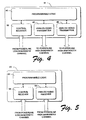
- Fig. 4 shows an example of an analog signal source such as VCR 16.
- VCR 16 has a control receiver 39 as already described, as well as its own programmable logic 40 that is connected to receive control data from the low-bandwidth communications channel through control receiver 39.
- VCR 16 has an associated analog audio signal transmitter 42 for transmitting an analog signal using a high-bandwidth frequency channel on the electrical power lines. This channel allows a relatively high bandwidth of, for example, approximately 36,000 bits per second.
- the high-bandwidth channel uses a carrier frequency of greater than approximately 3 MHz. In the described embodiment, the carrier frequency is between 3.5 MHz and 4.0 Mhz, divided into twenty high-bandwidth channels of approximately 50 kHz.
- the analog signal transmitter 42 is tunable or otherwise selectable between any one of the twenty high-bandwidth channels.
- programmable logic 40 controls the channel to which the transmitter is tuned, in response to control data received via control receiver 39.
- the transmitter is designed using conventional circuits such as used in wireless FM transmitters.
- a raw, non-digitized audio signal is frequency-modulated onto the selected carrier frequency of the selected channel.
- the audio signal is provided to the audio signal transmitter by playback electronics (not shown) in the VCR.
- VCR 16 has a second analog signal transmitter 46 for transmitting a video signal over the power lines using a high-bandwidth channel.
- Video requires an even higher bandwidth than audio, such as a 6 MHz bandwidth.
- the video signal transmitter 46 uses a channel chosen from five available 6 MHz channels having carrier frequencies between 420 MHz and 450 MHz. Again, FM modulation is used.
- Fig. 5 shows an example of an analog signal receiving device, in this case audio system 20.
- Audio system 20 has an audio signal receiver 50 that is connected to receive an audio signal over home electrical wiring.
- the receiver is an FM demodulator which produces a raw, non-digitized audio signal for amplification by other components (not shown).
- the receiver is tunable between any of the twenty available high-bandwidth audio channels.
- Programmable logic 52 is connected to control the operating frequency of receiver 50, again in response to control data received over the low-bandwidth communications channel.
- Audio system 20 has a control receiver 54 such as already described, which receives and demodulates control data using the low-bandwidth channel, and which provides the demodulated control data to programmable logic 52.
- Video monitor 18 has components that are similar to those of audio system 20, for receiving a video signal and providing it to rendering circuits.
- each electrical component has been described as having a specific set of transmitters and/or receivers, in practice any particular component is equipped with whatever transmitters and receivers are required to carry out the functions of the component.
- all of the electrical components might have control transmitters to provide bi-directional transfer of control data.
- analog signal transmitters and receivers are provided only in those components specifically requiring them, such as components that have a need to transmit or receive audio/video signals.
- audio/video signal means an analog, non-digitized signal that includes audio information, video information, or both audio and video information.
- a typical system has a plurality of components using control transmitters and receivers, and a plurality of components using analog signal transmitters and receivers. All components use the common, low-bandwidth control channels for relatively simple control communications. However, the analog signal sources and receivers use different high-bandwidth analog channels, with correspondingly different carrier frequencies.
- the invention has a number of advantages over the prior art.
- One advantage is that most components can be sold without high-bandwidth components. That is, only more sophisticated components are required to implement the analog signal transmitters and/or receivers. Other components, which have no need for high-speed communications, only need the relatively inexpensive control transmitters and/or receivers. This drastically reduces the cost of a complete system
- Another advantage is that the components using analog signals such as audio and video can be configured, after installation, for specific interconnections between devices, using different ones of the high-bandwidth channels.
- Controller 22 might consist of a small computer such as a laptop computer, having an associated control transmitter and control receiver to communicate with different electrical components using the low-bandwidth control channel.
- Controller 22 is configured to designate groups of analog signal sources and receivers, most likely in conjunction with a human operator. Each group comprises a single signal source and one or more receivers. Once such groups have been designated, the controller transmits control data to each member of the groups, using the low-bandwidth control channel. The control data commands each group to use a different one of the high-bandwidth communication channels. In effect, the controller sets up virtual analog connections between the source and receivers of each group. While the controller is shown as a separate component, it might alternatively be integrated in an analog signal source or receiver. For example, a VCR might include a controller that automatically sets up a virtual analog connection to an available receiver.
- a digital data modulator and demodulator are associated and used in conjunction with an analog signal transmitter and receiver as discussed above, respectively. This allows digital data to be transmitted from one component to another on the high-bandwidth analog signal channels. Data rates of approximately 36,000 bits per second can be achieved using the 50 kHz audio channels described above.
- the invention also includes steps that implement a method of communicating electronically between electrical components, using electrical power lines in a building. Such steps include modulating a first frequency channel on existing electrical power lines for low-bandwidth communications between components, and modulating a second frequency channel on the power lines for high-bandwidth communications between electrical components.
- the invention further includes transmitting control data between the electrical components on the first frequency channel, and transmitting analog signals between a group of components on the second frequency channel.
- the analog signals can be audio/video signals, or can include modulated digital content.
- the invention further includes designating source/receiver groups or pairs from the components and selecting a particular frequency for the high-bandwidth communications between the source and the receivers of each group.
- a further step comprises sending control data to each source/receiver group using the first frequency channel. The control data commands the components of each source/receiver group to use the second frequency channel selected for that group. As discussed above, the first frequency channel is at a lower frequency than the second frequency channel.
- a yet further step comprises modulating digital data on the analog signal transmitted by a particular analog signal transmitter, and demodulating the signal at a receiver.
Description
- This invention relates to automated home control systems and to methods of communicating between distributed components of a home control system using existing electrical wiring in a house or other building.
- A modem home potentially has a great number of sophisticated electrical systems, including security systems, audio/video systems, telephone systems, intercom systems, etc. All of these systems require interconnecting wiring. A security system for example, requires wiring between sensors, controllers, and alarm devices. Audio/video systems require a maze of wiring between different active components, as well as wiring to as many as six speakers in a single room. Telephone and intercom systems similarly require wires between stations.
- When systems such as these are installed during construction of a new home, wiring can be installed with little trouble. When adding system to an existing house, however, installation of required wiring often requires significant effort.
- Because of the difficulty of installing interconnecting wiring in an existing home, there are many available products that utilize existing AC power distribution wires or lines in a house for communications of various types. Products such as these work by modulating a signal on the power lines at a frequency that is well above the conventional 60 Hz frequency of electrical power carried by the distribution lines.
- An example of such a system is described in US 5,592,482. Therein, a cable television/video distribution and selection system is described, which makes use of electrical power lines as the transmission medium. A plurality of cable TV receivers are provided, each with a separate modulator to permit separate modulation of a CATV channel onto a different frequency on the electrical power line channel. At each TV, a control unit is provided having a dedicated control channel back to one of the receivers, to permit cable TV channel selection.
- As another example the so-called "X10" protocol is popular for providing simple communications between common electrical components such as security components, switchable power receptacles, dimmers, and other power control modules. The X10 system provides basic functionality between command modules and receivers of various types. In general, however, this system is limited to on/off and dimming capabilities.
- A variety of other products are also available. Some home intercoms, for example, modulate an analog audio signal on the power lines to provide audio communications between two different rooms in a house, without requiring dedicated wiring. Extension telephones are available that utilize existing power lines rather than requiring the installation of telephone cable. Adapters are also available for transmitting video and stereo audio over existing power lines in a house.
- There are a number of different protocols used for communications over existing building wiring. The relatively simple X10 communications protocol is one example. An X10 signal is composed of a series of 5 volt, 121 kHz pulses having a duration of 1 millisecond, positioned at zero crossings of the 60 Hz AC power signal. Each pulse corresponds to a binary 1, and the absence of a pulse corresponds to a binary 0. A single X10 command consists of a 22 bit word obtained from eleven complete cycles of the AC power signal.
- All X10 receivers plugged into the household power lines will see all transmitted signals. However, each command carries the address of its transmitter. A receiver responds to only those commands that have the address of the receiver. Thus, control modules such as switch modules can be paired with receiver modules by manually setting both addresses to the same value. Up to 256 addresses are available. Computer interfaces are available for allowing a computer to issue commands to different X10 receivers over home power lines.
- More sophisticated protocols have also been used to communicate using existing power lines. Electrical protocols in most such systems use a modulation carrier that is significantly higher in frequency than 60 Hz. Data formatting in the more sophisticated systems is similar or identical to networking protocols, in which discrete packets of digital information are sent from an originating device to a destination device using a common carrier channel or frequency. To send analog information, an analog signal is digitized and embedded in the packets.
- Simple control information such as used in X10 systems requires only a relatively low data bandwidth. Transmitters and receivers capable of such a low bandwidth are fairly inexpensive. Increasingly, however, there are other applications where higher bandwidth is necessary. For example, transmitting many types of analog information such as audio and video requires relatively high bandwidths. As another example, it might be desirable to provide a local area network for household computers and other computerized devices using existing power wiring. Higher bandwidths are required for these applications.
- Unfortunately, components capable of transmitting at high bandwidths are relatively expensive to produce: This has become an impediment to widespread acceptance and use of any standard that allows high bandwidth communications such as required for audio, video, and computer networking applications.
- From a first aspect, the present invention provides a system for electronic communications using electrical power lines in a building, comprising:
- a plurality of components that are connected for communications among themselves through the electrical power lines;
- a control transmitter associated with at least one of the components for transmitting control data using a frequency channel of a first type on the electrical power lines at a bandwidth of a first type;
- a control receiver associated with at least one of the components for receiving control data using the frequency channel of the first type;
- an analog signal source associated with at least one of the components for transmitting an analog signal using a frequency channel of a second type on the electrical power lines at a bandwidth of a second type.
- an analog signal receiver associated with at least one of the components for receiving the analog signal using the frequency channel of the second type;
- a plurality of the control transmitters (30) and receivers (34; 39; 54) associated with respective components, the control transmitters and receivers being configured to transmit and receive control data using the same frequency channel of the first type;
- at least one of said control transmitters being further configured to designate one or more source/receiver groups of the components and to send control data to each group using the frequency channel of the first type, wherein the control data commands each group to use a different frequency channel of the second type for transmission and reception of the analog signal.
- From a second aspect, the present invention also provides a system for electronic communications using electrical power lines in a building, comprising:
- a plurality of components that are connected for communications among themselves through the electrical power lines;
- a contmller for transmitting control data using a frequency channel of a first type on the electrical power lines at a bandwidth of a first type;
- a control receiver associated with at least one of the components for receiving control data using the frequency channel of the first type;
- an analog signal source associated with at least one of the components for transmitting an analog signal using a frequency channel of a second type on the electrical power lines at a bandwidth of a second type.
- an analog signal receiver associated with at least one of the components for receiving the analog signal using the frequency channel of the second type;
- From a third aspect, the present invention also provides a method of communicating electronically between a plurality of electrical components using electrical power lines in a building, comprising the following steps:
- modulating a common first frequency channel having a bandwidth of a first type on the electrical power lines for communications between electrical components; modulating a second frequency channel having a bandwidth of a second type on the electrical power lines for communications between electrical components; wherein the bandwidth of the first type is of a lower bandwidth than the bandwidth of the second type; said method being characterised by further comprising the steps of: -
- transmitting control data between the electrical components on the common first frequency channel;
- transmitting an analog signal between a group of the electrical components on the second frequency channel
- designating one or more source/receiver groups of the electrical components; and
- sending control data to each source/receiver group using the first frequency channel,
- The invention also provides electrical components according to
claims 13 and 18. Further features and aspects of the invention will be apparent from the appended claims. -
- Fig. 1 is a block diagram of a home control system in accordance with the invention.
- Fig. 2 is a block diagram of a switch module in accordance with the invention.
- Fig. 3 is a block diagram of a switchable outlet in accordance with the invention.
- Fig. 4 is a block diagram of a VCR in accordance with the invention.
- Fig. 5 is a block diagram of an audio system in accordance with the invention.
- Before describing a detailed embodiment of the invention, some key features of embodiments of the invention will be discussed.
- The invention includes a home automation system that utilizes a combination of high-bandwidth and low-bandwidth communication protocols over the same household electrical wiring. A system in accordance with the invention might include traditional lower-cost components such as light switches, dimrners, sensors, alarrns, switched power outlets, etc. Each of these devices is configured to communicate using a low-bandwidth communications channel established over existing household wiring.
- A system in accordance with the invention also includes components having a need for higher-bandwidth communications. These components are configured to use the low-bandwidth communications channel for control information. However, they are also configured to use one of a plurality of high-bandwidth communications channels for high-speed communications other components. Use of the high-bandwidth channels is managed by communicating over the low-bandwidth communications channel.
- As an example, a VCR is configured to receive control commands using the low bandwidth communications channel. Such commands might consist of on-off commands, tape transport commands, and programming commands. The VCR is also configured to transmit an audio/video signal over household electrical wiring using a high-bandwidth communications channel - typically using a higher carrier frequency than the low-bandwidth communications channel.
- Similarly, a TV or video monitor is configured to receive control commands using the low bandwidth communications channel, while also being configured to receive the audio/video signal over the high-bandwidth communications channel.
- In accordance with the invention, the high-bandwidth channel is selected from a plurality of available high-bandwidth channels that the VCR and TV are capable of using. A controller module is used to set up the VCR and TV to communicate using the same high-bandwidth channel. The controller issues commands to the VCR and TV over the low-bandwidth communications channel, instructing the components which high-bandwidth channel to use. A plurality of different component pairs or sets of components can coexist in the same household by using different high bandwidth channels.
- Once a particular high-bandwidth channel is selected, a pair or group of components can use any desired communications format. For example, an audio or video signal might be modulated directly onto the selected channel using amplitude or frequency modulation. Alternatively, digital data might be modulated onto the channel using traditional modem techniques. There is no need for the high-bandwidth formats to specify addresses or to accommodate general purpose control data. Thus, high-bandwidth formats used between components can be tailored to most efficiently meet the needs of the communicating devices.
- Embodiments of the invention will now be described.
- Fig. 1 shows an example of a
home control system 10 that useselectrical power lines 11 for communications. The system comprises a plurality of electrical components that are connected for communications among themselves through the electrical power lines. Such components comprise, for example, aswitch module 12, aswitchable outlet 14, a VCR (video cassette recorder) 16, avideo monitor 18, andaudio system 20, and acontroller 22. These components have control transmitters and/or control receivers, thus allowing the components to communicate digitally with each other on a low-bandwidth communications channel. Some of the components are also analog signal sources, while others are analog signal receivers. The analog signal sources and receivers communicate using one or more high-bandwidth communications channel. The low-bandwidth channel is preferably at a lower carrier frequency than the high-bandwidth channel. - Fig. 2 shows an example of a simple power control component such as
switch module 12. A component such as this has an associatedcontrol transmitter 30 that is connected to transmit control data using a low-bandwidth frequency channel on the electrical power lines. This channel allows only a relatively low bandwidth of, for example, 12 kHz or approximately 12,500 bits per second. The low-bandwidth channel uses a carrier frequency of less than approximately 500 KHz. In the described embodiment, the carrier frequency is 300 KHz, and data is modulated on the carrier using 2% frequency modulation. Data is transmitted with a series of marks and spaces, using a format as described in a co-pending US Patent Application by Gilad Odinak, Nigel Keam, and Craig Ranta, entitled "Bit Encoding in Home Control Systems," filed concurrently with this application, which is hereby incorporated by reference. Actual hardware is implemented using available integrated circuits designed for wireless FM modulation (such as National Semiconductor's LM2893, referred to as a Carrier Current Transceiver). Filtering is implemented to protect against power line surges and noise. -
Switch module 12 also has some type ofprogrammable logic 32 such as an inexpensive microprocessor or microcontroller. Theprogrammable logic 32 is connected to supply digital transmission data to controltransmitter 30. In response,transmitter 30 modulates the data on the low-bandwidth channel. The particular control data format is described in a co-pending US Patent Application by Gilad Odinak and Nigel Keam, entitled "Message Formatting, Authentication, and Error Detection in Home Control Systems," filed concurrently with this application, which is hereby incorporated by reference. In this case,switch module 12 transmits simple on/off commands. - Fig. 3 shows an example of a simple receiver component such as
switchable outlet 14. A component such as this has an associatedcontrol receiver 34 that is connected to receive control data using the low-bandwidth frequency channel. Again, the receiver is implemented using conventional circuitry such as commonly used to implement wireless communications systems, with precautions taken to protect against power line surges and noise.Switchable outlet 14 also hasprogrammable logic 36, as well aspower control circuitry 38. Data is demodulated from the low-bandwidth channel byreceiver 34 and provided toprogrammable logic 36.Power control circuitry 38 is responsive toprogrammable logic 36 to selectably provide power to a power outlet or integrated component (not shown). The control data format mentioned above allows an installer to assign virtual circuit numbers to each control component. A receiver is configured to respond only to commands having its virtual circuit number. - Fig. 4 shows an example of an analog signal source such as
VCR 16.VCR 16 has acontrol receiver 39 as already described, as well as its ownprogrammable logic 40 that is connected to receive control data from the low-bandwidth communications channel throughcontrol receiver 39. In addition,VCR 16 has an associated analogaudio signal transmitter 42 for transmitting an analog signal using a high-bandwidth frequency channel on the electrical power lines. This channel allows a relatively high bandwidth of, for example, approximately 36,000 bits per second. The high-bandwidth channel uses a carrier frequency of greater than approximately 3 MHz. In the described embodiment, the carrier frequency is between 3.5 MHz and 4.0 Mhz, divided into twenty high-bandwidth channels of approximately 50 kHz. Theanalog signal transmitter 42 is tunable or otherwise selectable between any one of the twenty high-bandwidth channels. Specifically,programmable logic 40 controls the channel to which the transmitter is tuned, in response to control data received viacontrol receiver 39. - Again, the transmitter is designed using conventional circuits such as used in wireless FM transmitters. In this case, a raw, non-digitized audio signal is frequency-modulated onto the selected carrier frequency of the selected channel. The audio signal is provided to the audio signal transmitter by playback electronics (not shown) in the VCR.
-
VCR 16 has a secondanalog signal transmitter 46 for transmitting a video signal over the power lines using a high-bandwidth channel. Video requires an even higher bandwidth than audio, such as a 6 MHz bandwidth. In the preferred embodiment, thevideo signal transmitter 46 uses a channel chosen from five available 6 MHz channels having carrier frequencies between 420 MHz and 450 MHz. Again, FM modulation is used. - Fig. 5 shows an example of an analog signal receiving device, in this case
audio system 20.Audio system 20 has anaudio signal receiver 50 that is connected to receive an audio signal over home electrical wiring. The receiver is an FM demodulator which produces a raw, non-digitized audio signal for amplification by other components (not shown). The receiver is tunable between any of the twenty available high-bandwidth audio channels.Programmable logic 52 is connected to control the operating frequency ofreceiver 50, again in response to control data received over the low-bandwidth communications channel.Audio system 20 has acontrol receiver 54 such as already described, which receives and demodulates control data using the low-bandwidth channel, and which provides the demodulated control data toprogrammable logic 52. - Video monitor 18 has components that are similar to those of
audio system 20, for receiving a video signal and providing it to rendering circuits. - Although each electrical component has been described as having a specific set of transmitters and/or receivers, in practice any particular component is equipped with whatever transmitters and receivers are required to carry out the functions of the component. For example, all of the electrical components might have control transmitters to provide bi-directional transfer of control data. However, analog signal transmitters and receivers are provided only in those components specifically requiring them, such as components that have a need to transmit or receive audio/video signals. In this document, the term "audio/video signal" means an analog, non-digitized signal that includes audio information, video information, or both audio and video information.
- Furthermore, a typical system has a plurality of components using control transmitters and receivers, and a plurality of components using analog signal transmitters and receivers. All components use the common, low-bandwidth control channels for relatively simple control communications. However, the analog signal sources and receivers use different high-bandwidth analog channels, with correspondingly different carrier frequencies.
- The invention has a number of advantages over the prior art. One advantage is that most components can be sold without high-bandwidth components. That is, only more sophisticated components are required to implement the analog signal transmitters and/or receivers. Other components, which have no need for high-speed communications, only need the relatively inexpensive control transmitters and/or receivers. This drastically reduces the cost of a complete system
- Another advantage is that the components using analog signals such as audio and video can be configured, after installation, for specific interconnections between devices, using different ones of the high-bandwidth channels.
- This can be accomplished with a controller such as
controller 22 of Fig. 1.Controller 22 might consist of a small computer such as a laptop computer, having an associated control transmitter and control receiver to communicate with different electrical components using the low-bandwidth control channel. -
Controller 22 is configured to designate groups of analog signal sources and receivers, most likely in conjunction with a human operator. Each group comprises a single signal source and one or more receivers. Once such groups have been designated, the controller transmits control data to each member of the groups, using the low-bandwidth control channel. The control data commands each group to use a different one of the high-bandwidth communication channels. In effect, the controller sets up virtual analog connections between the source and receivers of each group. While the controller is shown as a separate component, it might alternatively be integrated in an analog signal source or receiver. For example, a VCR might include a controller that automatically sets up a virtual analog connection to an available receiver. - In some situations, it might be desirable to transmit and receive digital data at high speeds. Such capability might be useful to implement a local area network within home. If this is the case, a digital data modulator and demodulator are associated and used in conjunction with an analog signal transmitter and receiver as discussed above, respectively. This allows digital data to be transmitted from one component to another on the high-bandwidth analog signal channels. Data rates of approximately 36,000 bits per second can be achieved using the 50 kHz audio channels described above.
- Although the invention has been described primarily in terms of its components and features, the invention also includes steps that implement a method of communicating electronically between electrical components, using electrical power lines in a building. Such steps include modulating a first frequency channel on existing electrical power lines for low-bandwidth communications between components, and modulating a second frequency channel on the power lines for high-bandwidth communications between electrical components. The invention further includes transmitting control data between the electrical components on the first frequency channel, and transmitting analog signals between a group of components on the second frequency channel. The analog signals can be audio/video signals, or can include modulated digital content.
- The invention further includes designating source/receiver groups or pairs from the components and selecting a particular frequency for the high-bandwidth communications between the source and the receivers of each group. A further step comprises sending control data to each source/receiver group using the first frequency channel. The control data commands the components of each source/receiver group to use the second frequency channel selected for that group. As discussed above, the first frequency channel is at a lower frequency than the second frequency channel. A yet further step comprises modulating digital data on the analog signal transmitted by a particular analog signal transmitter, and demodulating the signal at a receiver.
- Although the invention has been described in language more or less specific as to structural and methodological features, it is to be understood that the invention is not necessarily limited to the specific features or steps described. Rather, the specific features and steps are disclosed as preferred forms of implementing the invention.
wherein the analog signal is a signal other than an electrical power signal and wherein the bandwidth of the first type is of a lower bandwidth than the bandwidth of the second type;
the system being characterised by further comprising:
wherein the analog signal is a signal other than an electrical power signal and wherein the bandwidth of the first type is of a lower bandwidth than the bandwidth of the second type;
the system being characterised by further comprising a plurality of the receivers associated with respective components, the controller and the receivers being configured to transmit and receive control data using the same frequency channel of the first type;
the controller being further configured to designate one or more source/receiver groups of the components and to send control data to each group using the frequency channel of the first type, wherein the control data commands each group to use a different frequency channel of the second type for transmission and reception of the analog signal.
Claims (22)
- A system (10) for electronic communications using electrical power lines (11) in a building, comprising:a plurality of components (12, 14, 16, 18, 20, 22) that are connected for communications among themselves through the electrical power lines (11);a control transmitter (30) associated with at least one of the components for transmitting control data using a frequency channel of a first type on the electrical power lines (11) at a bandwidth of a first type;a control receiver (34; 39; 54) associated with at least one of the components for receiving control data using the frequency channel of the first type;an analog signal source (42, 46) associated with at least one of the components for transmitting an analog signal using a frequency channel of a second type on the electrical power lines at a bandwidth of a second type.an analog signal receiver (50) associated with at least one of the components for receiving the analog signal using the frequency channel of the second type;
wherein the analog signal is a signal other than an electrical power signal and wherein the bandwidth of the first type is of a lower bandwidth than the bandwidth of the second type;
the system being characterised by further comprising:a plurality of the control transmitters (30) and receivers (34; 39; 54) associated with respective components, the control transmitters and receivers being configured to transmit and receive control data using the same frequency channel of the first type;at least one of said control transmitters being further configured to designate one or more source/receiver groups of the components and to send control data to each group using the frequency channel of the first type, wherein the control data commands each group to use a different frequency channel of the second type for transmission and reception of the analog signal. - A system (10) for electronic communications using electrical power lines (11) in a building, comprising:a plurality of components (12, 14, 16, 18, 20, 22) that are connected for communications among themselves through the electrical power lines (11);a controller (22) for transmitting control data using a frequency channel of a first type on the electrical power lines (11) at a bandwidth of a first type;a control receiver (34; 39; 54) associated with at least one of the components for receiving control data using the frequency channel of the first type;an analog signal source (42, 46) associated with at least one of the components for transmitting an analog signal using a frequency channel of a second type on the electrical power lines at a bandwidth of a second type.an analog signal receiver (50) associated with at least one of the components for receiving the analog signal using the frequency channel of the second type;
wherein the analog signal is a signal other than an electrical power signal and wherein the bandwidth of the first type is of a lower bandwidth than the bandwidth of the second type;
the system being characterised by further comprising a plurality of the receivers (34; 39; 54) associated with respective components, the controller (22) and the receivers being configured to transmit and receive control data using the same frequency channel of the first type;
the controller (22) being further configured to designate one or more source/receiver groups of the components and to send control data to each group using the frequency channel of the first type, wherein the control data commands each group to use a different frequency channel of the second type for transmission and reception of the analog signal. - A system as recited in claims 1 or 2, wherein the frequency channel of the first type is at a lower frequency than the frequency channel of the second type.
- A system as recited in claims 1 or 2, wherein the frequency channel of the first type is at a frequency of less than 500 KHz and the frequency channel of the second type is at a frequency of greater than 3 MHz.
- A system as recited in claims 1 or 2, further comprising a plurality of the analog signal sources and receivers associated with respective components, the analog signal sources and receivers being configured to transmit and receive analog signals using different frequency channels of the second type.
- A system as recited in claims 1 or 2, wherein the frequency channel of the second type used by the analog signal source and the analog signal receiver is selectable in response to control data transmitted using the frequency channel of the first type.
- A system as recited in claims 1 or 2, wherein the analog signal is an audio/video signal.
- A system as recited in claims 1 or 2, further comprising;
a modulator associated with the analog signal source to modulate digital data on the analog signal;
a demodulator associated with the analog signal receiver to demodulate digital data from the analog signal. - A method of communicating electronically between a plurality of electrical components (12, 14, 16, 18, 20, 22) using electrical power lines (11) in a building, comprising the following steps:modulating a common first frequency channel having a bandwidth of a first type on the electrical power lines (11) for communications between electrical components (12, 14, 16, 18, 20, 22); modulating a second frequency channel having a bandwidth of a second type on the electrical power lines (11) for communications between electrical components (12, 14, 16, 18, 20, 22); wherein the bandwidth of the first type is of a lower bandwidth than the bandwidth of the second type; said method being characterised by further comprising the steps of: -transmitting control data between the electrical components (12, 14, 16, 18, 20, 22) on the common first frequency channel;transmitting an analog signal between a group of the electrical components (12, 14, 16, 18, 20, 22) on the second frequency channeldesignating one or more source/receiver groups of the electrical components; andsending control data to each source/receiver group using the first frequency channel, wherein the control data commands each group to use a different frequency for the second frequency channel.
- A method as recited in claim 9, wherein the analog signal is an analog audio/video signal.
- A method as recited in claim 9, wherein the analog signal carries digital content.
- A method as recited in claim 9, wherein the first frequency channel is at a lower frequency than the second frequency channel.
- An electrical component (20) for connection to electrical wiring (11) in a building, comprising:a control receiver (54) that receives control data using a common frequency channel of a first type on the electrical power lines at a bandwidth of a first type;an analog signal receiver (50) that receives an analog signal using a frequency channel of a second type on the electrical power lines at a bandwidth of a second type;wherein the bandwidth of the first type is of the lower bandwidth than the bandwidth of the second type;wherein the analog signal is a signal other than an electrical power signal, and wherein the common frequency channel of the first type is also used by other control receivers forming part of other electrical components;the control receiver (54) being further arranged to receive control data designating the electrical component (20) as a member of a source/receiver group and commanding the electrical component (20) to use a particular frequency channel of the second type for reception of the analog signal by the analog signal receiver (50), the particular frequency channel used being different to frequency channels used by other source/receiver groups.
- An electrical component as recited in claim 13, further comprising a control transmitter that transmits control data using the frequency channel of the first type on the electrical power lines at the bandwidth of the first type.
- An electrical component as recited in claim 13, wherein the electrical component is responsive to the control data to use a particular frequency channel of the second type from a plurality of frequency channels of the second type that the electrical component is capable of using.
- An electrical component as recited in claim 13, wherein the analog signal is an audio/video signal.
- An electrical component as recited in claim 13, wherein the low frequency channel of the first type is at a lower frequency than the frequency channel of the second type.
- An electrical component (16) for connection to electrical wiring (11) in a building, comprising:a control receiver (39) that receives control data using a common frequency channel of a first type on the electrical power lines at a bandwidth of a first type;an analog signal transmitter (42, 46) that transmits an analog signal using a frequency channel of a second type on the electrical power lines at a bandwidth of a second type;wherein the bandwidth of the first type is of a lower bandwidth than the bandwidth of the second type;wherein the analog signal is a signal other than an electrical power signal, and wherein the common frequency channel of the first type is also used by other control receivers forming part of other electrical components;the control receiver (39) being further arranged to receive control data designating the electrical component (16) as a member of a source/receiver group and commanding the electrical component (16) to use a particular frequency channel of the second type for transmission of the analog signal by the analog signal transmitter (42,46), the particular frequency channel used being different to frequency channels used by other source/receiver groups.
- An electrical component as recited in claim 18, further comprising a control transmitter that transmits control data using the frequency channel of the first type on the electrical power lines at the bandwidth of the first type.
- An electrical component as recited in claim 18, wherein the electrical component is responsive to the control data to use a particular frequency channel of the second type from a plurality of frequency channels of the second type that the electrical component is capable of using.
- An electrical component as recited in claim 18, wherein the analog signal is an audio/video signal.
- An electrical component as recited in claim 18, wherein the frequency channel of the first type is at a lower frequency than the frequency channel of the second type.
Priority Applications (1)
| Application Number | Priority Date | Filing Date | Title |
|---|---|---|---|
| EP05012490A EP1578062B1 (en) | 1997-06-12 | 1998-06-12 | Automated home control using existing electrical lines as a communications medium |
Applications Claiming Priority (3)
| Application Number | Priority Date | Filing Date | Title |
|---|---|---|---|
| US08/874,045 US5929748A (en) | 1997-06-12 | 1997-06-12 | Automated home control using existing electrical lines as a communications medium |
| US874045 | 1997-06-12 | ||
| PCT/US1998/012292 WO1998057462A1 (en) | 1997-06-12 | 1998-06-12 | Automated home control using existing electrical lines as a communications medium |
Related Child Applications (1)
| Application Number | Title | Priority Date | Filing Date |
|---|---|---|---|
| EP05012490A Division EP1578062B1 (en) | 1997-06-12 | 1998-06-12 | Automated home control using existing electrical lines as a communications medium |
Publications (2)
| Publication Number | Publication Date |
|---|---|
| EP0986876A1 EP0986876A1 (en) | 2000-03-22 |
| EP0986876B1 true EP0986876B1 (en) | 2006-03-08 |
Family
ID=25362870
Family Applications (2)
| Application Number | Title | Priority Date | Filing Date |
|---|---|---|---|
| EP98930189A Expired - Lifetime EP0986876B1 (en) | 1997-06-12 | 1998-06-12 | Automated home control system using existing electrical lines as a communication medium |
| EP05012490A Expired - Lifetime EP1578062B1 (en) | 1997-06-12 | 1998-06-12 | Automated home control using existing electrical lines as a communications medium |
Family Applications After (1)
| Application Number | Title | Priority Date | Filing Date |
|---|---|---|---|
| EP05012490A Expired - Lifetime EP1578062B1 (en) | 1997-06-12 | 1998-06-12 | Automated home control using existing electrical lines as a communications medium |
Country Status (6)
| Country | Link |
|---|---|
| US (2) | US5929748A (en) |
| EP (2) | EP0986876B1 (en) |
| JP (2) | JP2002504288A (en) |
| AU (1) | AU7964298A (en) |
| DE (2) | DE69833757T2 (en) |
| WO (1) | WO1998057462A1 (en) |
Families Citing this family (98)
| Publication number | Priority date | Publication date | Assignee | Title |
|---|---|---|---|---|
| US6808472B1 (en) | 1995-12-14 | 2004-10-26 | Paul L. Hickman | Method and apparatus for remote interactive exercise and health equipment |
| US6175860B1 (en) * | 1997-11-26 | 2001-01-16 | International Business Machines Corporation | Method and apparatus for an automatic multi-rate wireless/wired computer network |
| EP1055177A1 (en) * | 1998-01-22 | 2000-11-29 | Intelogis, Inc. | Method and apparatus for universal data exchange gateway |
| US6480510B1 (en) | 1998-07-28 | 2002-11-12 | Serconet Ltd. | Local area network of serial intelligent cells |
| US6297729B1 (en) * | 1999-03-29 | 2001-10-02 | International Business Machines Corporation | Method and apparatus for securing communications along ac power lines |
| US6408272B1 (en) * | 1999-04-12 | 2002-06-18 | General Magic, Inc. | Distributed voice user interface |
| US20050261907A1 (en) | 1999-04-12 | 2005-11-24 | Ben Franklin Patent Holding Llc | Voice integration platform |
| DE19923323A1 (en) * | 1999-05-21 | 2000-11-23 | Deutsche Telekom Ag | Remote power switching unit has telephone control for many user units uses power lines to carry control signals. |
| US7099621B1 (en) * | 1999-06-25 | 2006-08-29 | Cocomo Mb Communications, Inc. | Electromagnetic field communications system for wireless networks |
| US6458060B1 (en) | 1999-07-08 | 2002-10-01 | Icon Ip, Inc. | Systems and methods for interaction with exercise device |
| US7628730B1 (en) | 1999-07-08 | 2009-12-08 | Icon Ip, Inc. | Methods and systems for controlling an exercise apparatus using a USB compatible portable remote device |
| US7985164B2 (en) | 1999-07-08 | 2011-07-26 | Icon Ip, Inc. | Methods and systems for controlling an exercise apparatus using a portable data storage device |
| US7060006B1 (en) | 1999-07-08 | 2006-06-13 | Icon Ip, Inc. | Computer systems and methods for interaction with exercise device |
| US7166062B1 (en) | 1999-07-08 | 2007-01-23 | Icon Ip, Inc. | System for interaction with exercise device |
| US6918858B2 (en) * | 1999-07-08 | 2005-07-19 | Icon Ip, Inc. | Systems and methods for providing an improved exercise device with access to motivational programming over telephone communication connection lines |
| US7537546B2 (en) | 1999-07-08 | 2009-05-26 | Icon Ip, Inc. | Systems and methods for controlling the operation of one or more exercise devices and providing motivational programming |
| US6447424B1 (en) * | 2000-02-02 | 2002-09-10 | Icon Health & Fitness Inc | System and method for selective adjustment of exercise apparatus |
| US8029415B2 (en) | 1999-07-08 | 2011-10-04 | Icon Ip, Inc. | Systems, methods, and devices for simulating real world terrain on an exercise device |
| US6312363B1 (en) | 1999-07-08 | 2001-11-06 | Icon Health & Fitness, Inc. | Systems and methods for providing an improved exercise device with motivational programming |
| US6997852B2 (en) | 1999-07-08 | 2006-02-14 | Icon Ip, Inc. | Methods and systems for controlling an exercise apparatus using a portable remote device |
| US6856614B1 (en) | 1999-12-24 | 2005-02-15 | Lara Networks, Inc. | Method for a mixed voice and data device in a home communications network |
| US6724750B1 (en) | 1999-12-24 | 2004-04-20 | Lara Networks, Inc. | Method for a link to a wide area network device in a home communication network |
| US7130297B1 (en) | 2000-03-06 | 2006-10-31 | Sun Peter C P | Architecture for a mixed voice and data network |
| US6842459B1 (en) | 2000-04-19 | 2005-01-11 | Serconet Ltd. | Network combining wired and non-wired segments |
| US6909921B1 (en) | 2000-10-19 | 2005-06-21 | Destiny Networks, Inc. | Occupancy sensor and method for home automation system |
| US6792319B1 (en) | 2000-10-19 | 2004-09-14 | Destiny Networks, Inc. | Home automation system and method |
| US6912429B1 (en) | 2000-10-19 | 2005-06-28 | Destiny Networks, Inc. | Home automation system and method |
| US6756998B1 (en) | 2000-10-19 | 2004-06-29 | Destiny Networks, Inc. | User interface and method for home automation system |
| US8127326B2 (en) | 2000-11-14 | 2012-02-28 | Claussen Paul J | Proximity detection using wireless connectivity in a communications system |
| CA2428946C (en) | 2000-11-14 | 2010-06-22 | Scientific-Atlanta, Inc. | Networked subscriber television distribution |
| WO2003015359A1 (en) * | 2001-08-04 | 2003-02-20 | Enikia Llc | Network-to-network adaptor for power line communications |
| US6921351B1 (en) | 2001-10-19 | 2005-07-26 | Cybergym, Inc. | Method and apparatus for remote interactive exercise and health equipment |
| AU2003206092A1 (en) * | 2002-03-12 | 2003-09-22 | Philips Intellectual Property And Standards Gmbh | Coupling module for a network |
| AU2003225041A1 (en) * | 2002-04-17 | 2003-11-03 | Black And Decker Inc. | Home automation system |
| US7092772B2 (en) * | 2002-04-17 | 2006-08-15 | Black & Decker Inc. | Home automation system |
| US7516470B2 (en) | 2002-08-02 | 2009-04-07 | Cisco Technology, Inc. | Locally-updated interactive program guide |
| US6771164B1 (en) | 2002-09-05 | 2004-08-03 | Nrc Corporation | Automatic identification of local devices |
| FR2844600A1 (en) * | 2002-09-13 | 2004-03-19 | Thomson Licensing Sa | Second subscription domestic e.g. television, apparatus checking relative position domestic network method having alternating electrical periods measured first/second apparatus and offset comparison verified/not verified |
| US7234115B1 (en) | 2002-09-26 | 2007-06-19 | Home Director, Inc. | Home entertainment system and method |
| US20040068753A1 (en) * | 2002-10-02 | 2004-04-08 | Robertson Neil C. | Video transmission systems and methods for a home network |
| US7908625B2 (en) * | 2002-10-02 | 2011-03-15 | Robertson Neil C | Networked multimedia system |
| US8046806B2 (en) | 2002-10-04 | 2011-10-25 | Wall William E | Multiroom point of deployment module |
| US7360235B2 (en) | 2002-10-04 | 2008-04-15 | Scientific-Atlanta, Inc. | Systems and methods for operating a peripheral record/playback device in a networked multimedia system |
| US7545935B2 (en) | 2002-10-04 | 2009-06-09 | Scientific-Atlanta, Inc. | Networked multimedia overlay system |
| AU2003291252A1 (en) * | 2002-11-06 | 2004-06-03 | Ambient Corporation | Controlling power output of a modem for power line communications |
| US8094640B2 (en) | 2003-01-15 | 2012-01-10 | Robertson Neil C | Full duplex wideband communications system for a local coaxial network |
| US7487532B2 (en) | 2003-01-15 | 2009-02-03 | Cisco Technology, Inc. | Optimization of a full duplex wideband communications system |
| US7042353B2 (en) | 2003-02-03 | 2006-05-09 | Ingrid, Inc. | Cordless telephone system |
| US7119658B2 (en) | 2003-02-03 | 2006-10-10 | Ingrid, Inc. | Device enrollment in a security system |
| US7091827B2 (en) | 2003-02-03 | 2006-08-15 | Ingrid, Inc. | Communications control in a security system |
| US7079034B2 (en) | 2003-02-03 | 2006-07-18 | Ingrid, Inc. | RFID transponder for a security system |
| US20060132302A1 (en) * | 2003-02-03 | 2006-06-22 | Stilp Louis A | Power management of transponders and sensors in an RFID security network |
| US7057512B2 (en) | 2003-02-03 | 2006-06-06 | Ingrid, Inc. | RFID reader for a security system |
| US7283048B2 (en) * | 2003-02-03 | 2007-10-16 | Ingrid, Inc. | Multi-level meshed security network |
| US7532114B2 (en) * | 2003-02-03 | 2009-05-12 | Ingrid, Inc. | Fixed part-portable part communications network for a security network |
| US7495544B2 (en) * | 2003-02-03 | 2009-02-24 | Ingrid, Inc. | Component diversity in a RFID security network |
| US6888459B2 (en) * | 2003-02-03 | 2005-05-03 | Louis A. Stilp | RFID based security system |
| US7079020B2 (en) * | 2003-02-03 | 2006-07-18 | Ingrid, Inc. | Multi-controller security network |
| US7019639B2 (en) | 2003-02-03 | 2006-03-28 | Ingrid, Inc. | RFID based security network |
| US7511614B2 (en) * | 2003-02-03 | 2009-03-31 | Ingrid, Inc. | Portable telephone in a security network |
| US7053764B2 (en) * | 2003-02-03 | 2006-05-30 | Ingrid, Inc. | Controller for a security system |
| US7023341B2 (en) | 2003-02-03 | 2006-04-04 | Ingrid, Inc. | RFID reader for a security network |
| IL154921A (en) | 2003-03-13 | 2011-02-28 | Mosaid Technologies Inc | Telephone system having multiple distinct sources and accessories therefor |
| US20040215750A1 (en) * | 2003-04-28 | 2004-10-28 | Stilp Louis A. | Configuration program for a security system |
| US8291009B2 (en) | 2003-04-30 | 2012-10-16 | Silicon Graphics International Corp. | System, method, and computer program product for applying different transport mechanisms for user interface and image portions of a remotely rendered image |
| US7206643B2 (en) * | 2003-12-10 | 2007-04-17 | Nokia Corporation | Apparatus, system, and method for automation using automation modules |
| US7345998B2 (en) * | 2004-12-15 | 2008-03-18 | Smart Labs, Inc. | Mesh network of intelligent devices communicating via powerline and radio frequency |
| US7856032B2 (en) * | 2005-04-04 | 2010-12-21 | Current Technologies, Llc | Multi-function modem device |
| US7876998B2 (en) | 2005-10-05 | 2011-01-25 | Wall William E | DVD playback over multi-room by copying to HDD |
| US20070150565A1 (en) | 2005-12-22 | 2007-06-28 | Arun Ayyagari | Surveillance network system |
| US7852207B2 (en) * | 2006-02-14 | 2010-12-14 | Current Technologies, Llc | Method for establishing power line communication link |
| US20070217414A1 (en) * | 2006-03-14 | 2007-09-20 | Berkman William H | System and method for multicasting over power lines |
| US7596079B2 (en) * | 2006-05-31 | 2009-09-29 | Current Technologies, Llc | System and method for communicating in a multi-unit structure |
| US7602695B2 (en) * | 2006-05-31 | 2009-10-13 | Current Technologies, Llc | System and method for communicating in a multi-unit structure |
| CN100525231C (en) * | 2006-09-06 | 2009-08-05 | 中国移动通信集团公司 | Energy-saving information household appliance network and energy-saving control method |
| GB2446848A (en) * | 2007-01-12 | 2008-08-27 | Technetix Ltd | A filter for providing higher frequency information carrying signals on the same conductor as a lower frequency power carrying signal |
| JP4726829B2 (en) * | 2007-03-05 | 2011-07-20 | 三菱電機株式会社 | Electric line carrier communication system |
| US20090092236A1 (en) * | 2007-10-08 | 2009-04-09 | Jeffrey Vaughn Wilson | System and method for integrated intercom and distributed audio/video system with security interface |
| WO2009120984A1 (en) | 2008-03-28 | 2009-10-01 | Kopin Corporation | Handheld wireless display device having high-resolution display suitable for use as a mobile internet device |
| US8174148B2 (en) * | 2008-08-07 | 2012-05-08 | Crucs Holdings, Llc | Controllable electrical outlet and a method of operation thereof |
| US8251874B2 (en) | 2009-03-27 | 2012-08-28 | Icon Health & Fitness, Inc. | Exercise systems for simulating real world terrain |
| CN101916092B (en) * | 2010-07-19 | 2012-08-22 | 北京中电飞华通信股份有限公司 | Switching value controller, interactive terminal and intelligent home control system and method |
| US10013976B2 (en) | 2010-09-20 | 2018-07-03 | Kopin Corporation | Context sensitive overlays in voice controlled headset computer displays |
| IT1403724B1 (en) * | 2011-01-13 | 2013-10-31 | Vimar Spa | DOMOTIC SYSTEM |
| WO2012154938A1 (en) | 2011-05-10 | 2012-11-15 | Kopin Corporation | Headset computer that uses motion and voice commands to control information display and remote devices |
| US9339691B2 (en) | 2012-01-05 | 2016-05-17 | Icon Health & Fitness, Inc. | System and method for controlling an exercise device |
| US8929954B2 (en) * | 2012-04-25 | 2015-01-06 | Kopin Corporation | Headset computer (HSC) as auxiliary display with ASR and HT input |
| WO2014153158A1 (en) | 2013-03-14 | 2014-09-25 | Icon Health & Fitness, Inc. | Strength training apparatus with flywheel and related methods |
| US20150113296A1 (en) * | 2013-10-17 | 2015-04-23 | Trippe Manufacturing Company | System and method for automated inventory of power receptacle, asset, and rack space locations |
| EP3623020A1 (en) | 2013-12-26 | 2020-03-18 | Icon Health & Fitness, Inc. | Magnetic resistance mechanism in a cable machine |
| US10433612B2 (en) | 2014-03-10 | 2019-10-08 | Icon Health & Fitness, Inc. | Pressure sensor to quantify work |
| CN106470739B (en) | 2014-06-09 | 2019-06-21 | 爱康保健健身有限公司 | It is incorporated to the funicular system of treadmill |
| WO2015195965A1 (en) | 2014-06-20 | 2015-12-23 | Icon Health & Fitness, Inc. | Post workout massage device |
| US10391361B2 (en) | 2015-02-27 | 2019-08-27 | Icon Health & Fitness, Inc. | Simulating real-world terrain on an exercise device |
| US10272317B2 (en) | 2016-03-18 | 2019-04-30 | Icon Health & Fitness, Inc. | Lighted pace feature in a treadmill |
| US10493349B2 (en) | 2016-03-18 | 2019-12-03 | Icon Health & Fitness, Inc. | Display on exercise device |
| US10625137B2 (en) | 2016-03-18 | 2020-04-21 | Icon Health & Fitness, Inc. | Coordinated displays in an exercise device |
| US10671705B2 (en) | 2016-09-28 | 2020-06-02 | Icon Health & Fitness, Inc. | Customizing recipe recommendations |
Family Cites Families (16)
| Publication number | Priority date | Publication date | Assignee | Title |
|---|---|---|---|---|
| US3643023A (en) * | 1968-03-01 | 1972-02-15 | Milgo Electronic Corp | Differential phase modulator and demodulator utilizing relative phase differences at the center of the modulation periods |
| US3911415A (en) * | 1973-12-18 | 1975-10-07 | Westinghouse Electric Corp | Distribution network power line carrier communication system |
| DE3114063A1 (en) * | 1981-04-07 | 1982-10-21 | Licentia Patent-Verwaltungs-Gmbh, 6000 Frankfurt | RECEPTION SYSTEM |
| JPS61131624A (en) * | 1984-11-29 | 1986-06-19 | Nec Corp | Power line communication system |
| US4757495A (en) * | 1986-03-05 | 1988-07-12 | Telebit Corporation | Speech and data multiplexor optimized for use over impaired and bandwidth restricted analog channels |
| GB8707533D0 (en) * | 1987-03-30 | 1987-05-07 | Indep Broadcasting Authority | Pre-emphasis for(mac)television signal |
| JPH01101085A (en) * | 1987-10-14 | 1989-04-19 | Mitsubishi Electric Corp | Video information transmission system |
| US5592482A (en) * | 1989-04-28 | 1997-01-07 | Abraham; Charles | Video distribution system using in-wall wiring |
| JPH0374944A (en) * | 1989-08-15 | 1991-03-29 | Matsushita Electric Works Ltd | Frequency division multiplex transmission system |
| US5327230A (en) * | 1989-09-20 | 1994-07-05 | Dockery Gregory A | Video multiplying system |
| US5355114A (en) * | 1991-05-10 | 1994-10-11 | Echelon Corporation | Reconstruction of signals using redundant channels |
| US5263046A (en) * | 1992-05-08 | 1993-11-16 | Intellon Corporation | Spread-spectrum chirp communication with sharply defined bandwidth |
| FR2691863B1 (en) * | 1992-05-27 | 1995-06-23 | Koubi Denis | METHOD AND SYSTEM FOR TRANSMITTING BROADBAND ANALOG AND / OR DIGITAL INFORMATION AND SIGNALS USING THE ELECTRICAL POWER DISTRIBUTION NETWORK AS A TRANSMISSION MEDIUM. |
| US5452344A (en) * | 1992-05-29 | 1995-09-19 | Datran Systems Corporation | Communication over power lines |
| AU705571B2 (en) * | 1994-01-11 | 1999-05-27 | Videocom, Inc. | A system and method for high speed communication of video, voice and error-free data over in-wall wiring |
| US5777769A (en) * | 1995-12-28 | 1998-07-07 | Lucent Technologies Inc. | Device and method for providing high speed data transfer through a drop line of a power line carrier communication system |
-
1997
- 1997-06-12 US US08/874,045 patent/US5929748A/en not_active Expired - Lifetime
-
1998
- 1998-06-12 EP EP98930189A patent/EP0986876B1/en not_active Expired - Lifetime
- 1998-06-12 JP JP50327699A patent/JP2002504288A/en active Pending
- 1998-06-12 DE DE69833757T patent/DE69833757T2/en not_active Expired - Lifetime
- 1998-06-12 WO PCT/US1998/012292 patent/WO1998057462A1/en active IP Right Grant
- 1998-06-12 AU AU79642/98A patent/AU7964298A/en not_active Abandoned
- 1998-06-12 EP EP05012490A patent/EP1578062B1/en not_active Expired - Lifetime
- 1998-06-12 DE DE69842261T patent/DE69842261D1/en not_active Expired - Lifetime
-
1999
- 1999-04-19 US US09/294,746 patent/US6091320A/en not_active Expired - Lifetime
-
2008
- 2008-07-10 JP JP2008180653A patent/JP2008278536A/en active Pending
Also Published As
| Publication number | Publication date |
|---|---|
| JP2008278536A (en) | 2008-11-13 |
| US6091320A (en) | 2000-07-18 |
| JP2002504288A (en) | 2002-02-05 |
| DE69833757D1 (en) | 2006-05-04 |
| EP0986876A1 (en) | 2000-03-22 |
| WO1998057462A1 (en) | 1998-12-17 |
| AU7964298A (en) | 1998-12-30 |
| EP1578062A1 (en) | 2005-09-21 |
| DE69842261D1 (en) | 2011-06-16 |
| DE69833757T2 (en) | 2006-11-23 |
| US5929748A (en) | 1999-07-27 |
| EP1578062B1 (en) | 2011-05-04 |
Similar Documents
| Publication | Publication Date | Title |
|---|---|---|
| EP0986876B1 (en) | Automated home control system using existing electrical lines as a communication medium | |
| US6348875B1 (en) | Message formatting, authentication, and error detection in home control systems | |
| US5351272A (en) | Communications apparatus and method for transmitting and receiving multiple modulated signals over electrical lines | |
| US7292600B2 (en) | Local area network of serial intellegent cells | |
| WO2000018098A1 (en) | Method and system for distribution of wireless signals for increased wireless coverage using the power lines | |
| CA2350727A1 (en) | Entertainment and computer coaxial network and method of distributing signals therethrough | |
| US6064297A (en) | Message authentication and key synchronization in home control systems | |
| US6771164B1 (en) | Automatic identification of local devices | |
| US4384356A (en) | Wide band modem for high speed data transmission | |
| KR100264094B1 (en) | Signal processing system and apparatus using this system | |
| US6144291A (en) | Bit encoding in home control systems | |
| CA2327417A1 (en) | Distribution system for external communication signals and data | |
| AU769110B2 (en) | Digital telephony carrier current system | |
| JPH0310491A (en) | Cctv data communication system | |
| JP2000201384A (en) | Network control system | |
| Kurobe et al. | Small-scale condominium information system based on home-bus | |
| O'Brien | Physical and media specifications of the CXBus | |
| KR20010013187A (en) | Twisted pair communication system | |
| JPH10210576A (en) | Remote transmission capability variable device | |
| JPH06101735B2 (en) | Information transmission device | |
| WO2004002154A2 (en) | System for the reception, processing, and distribution of signals |
Legal Events
| Date | Code | Title | Description |
|---|---|---|---|
| PUAI | Public reference made under article 153(3) epc to a published international application that has entered the european phase |
Free format text: ORIGINAL CODE: 0009012 |
|
| 17P | Request for examination filed |
Effective date: 19991217 |
|
| AK | Designated contracting states |
Kind code of ref document: A1 Designated state(s): DE FR GB |
|
| 17Q | First examination report despatched |
Effective date: 20040712 |
|
| RTI1 | Title (correction) |
Free format text: AUTOMATED HOME CONTROL SYSTEM USING EXISTING ELECTRICAL LINES AS A COMMUNICATION MEDIUM |
|
| GRAP | Despatch of communication of intention to grant a patent |
Free format text: ORIGINAL CODE: EPIDOSNIGR1 |
|
| GRAS | Grant fee paid |
Free format text: ORIGINAL CODE: EPIDOSNIGR3 |
|
| GRAA | (expected) grant |
Free format text: ORIGINAL CODE: 0009210 |
|
| AK | Designated contracting states |
Kind code of ref document: B1 Designated state(s): DE FR GB |
|
| REG | Reference to a national code |
Ref country code: GB Ref legal event code: FG4D |
|
| REF | Corresponds to: |
Ref document number: 69833757 Country of ref document: DE Date of ref document: 20060504 Kind code of ref document: P |
|
| ET | Fr: translation filed | ||
| PLBE | No opposition filed within time limit |
Free format text: ORIGINAL CODE: 0009261 |
|
| STAA | Information on the status of an ep patent application or granted ep patent |
Free format text: STATUS: NO OPPOSITION FILED WITHIN TIME LIMIT |
|
| 26N | No opposition filed |
Effective date: 20061211 |
|
| PGFP | Annual fee paid to national office [announced via postgrant information from national office to epo] |
Ref country code: DE Payment date: 20120607 Year of fee payment: 15 |
|
| PGFP | Annual fee paid to national office [announced via postgrant information from national office to epo] |
Ref country code: FR Payment date: 20120619 Year of fee payment: 15 Ref country code: GB Payment date: 20120606 Year of fee payment: 15 |
|
| GBPC | Gb: european patent ceased through non-payment of renewal fee |
Effective date: 20130612 |
|
| REG | Reference to a national code |
Ref country code: DE Ref legal event code: R119 Ref document number: 69833757 Country of ref document: DE Effective date: 20140101 |
|
| REG | Reference to a national code |
Ref country code: FR Ref legal event code: ST Effective date: 20140228 |
|
| PG25 | Lapsed in a contracting state [announced via postgrant information from national office to epo] |
Ref country code: DE Free format text: LAPSE BECAUSE OF NON-PAYMENT OF DUE FEES Effective date: 20140101 Ref country code: GB Free format text: LAPSE BECAUSE OF NON-PAYMENT OF DUE FEES Effective date: 20130612 |
|
| PG25 | Lapsed in a contracting state [announced via postgrant information from national office to epo] |
Ref country code: FR Free format text: LAPSE BECAUSE OF NON-PAYMENT OF DUE FEES Effective date: 20130701 |